Embed Size (px)
Citation preview

SINTEF Fisheries and Aquaculture Fisheries Technology 2012-08-31
A23318- Unrestricted
Report
MultiSEPT – Initial model scale tests of traditional and alternative trawl ground gears Author(s) Svein Helge Gjøsund Kurt Hansen Manu Sistiaga Eduardo Grimaldo


PROJECT NO. 830292
REPORT NO. A23318
VERSION 1.0
2 of 34
Table of contents
1 Introduction .................................................................................................................................. 3
2 Materials and Methods.................................................................................................................. 4 2.1 Overall test plan ............................................................................................................................. 4 2.2 Scaling ............................................................................................................................................ 6 2.3 Load cells ........................................................................................................................................ 6 2.4 Bottom obstacles ........................................................................................................................... 7 2.5 Models ......................................................................................................................................... 10
2.5.1 Trawl ................................................................................................................................ 10 2.5.2 Rockhopper (RH) .............................................................................................................. 11 2.5.3 Brush gear (B) .................................................................................................................. 11 2.5.4 Skirt (S) ............................................................................................................................. 12 2.5.5 Modified skirt (MS1 and MS2) ......................................................................................... 14 2.5.6 Modified plate gear (MP1 and MP2) ............................................................................... 15 2.5.7 Semi-circular spreading gear (SCSG1 and SCSG2) ........................................................... 21
3 Results ........................................................................................................................................ 24 3.1 Tabulated summary of results ..................................................................................................... 24
4 Discussion ................................................................................................................................... 28 4.1 Average tension in lower sweep, headline, fishing line and gear chains .................................... 28
4.1.1 Week 21, Table 4 ............................................................................................................. 28 4.1.2 Week 27, Table 5 ............................................................................................................. 29
4.2 Maximum tension in in lower sweep, headline, fishing line and gear chains when the bottom gear is retained by a bottom obstacle ......................................................................................... 30 4.2.1 Week 21, Table 4 ............................................................................................................. 30 4.2.2 Week 27, Table 5 ............................................................................................................. 31
5 Summary of results and conclusions ............................................................................................. 32
6 References .................................................................................................................................. 34
PROJECT NO. 830292
REPORT NO. A23318
VERSION 1.0
3 of 34
1 Introduction This report is a part of the research project Development of multirig semi-pelagic trawling – MultiSEPT (Research Council of Norway project no. 216423, The Norwegian Seafood Research Fund project no. 900740). The main objective of the project is to reduce NOx- and other environmental emissions and to increase the energy efficiency of trawling operations for deep-water resources such as Northern shrimp and Northeast Arctic cod, by developing multi-rig semi-pelagic trawling technology. The specific sub-goals of the project are to: • develop a multi-rig semi-pelagic trawl (twin and triple trawl) in which trawl doors, central clump(s) and
sweeps have no physical contact with the seabed. • develop a trawl surveillance concept based on state-of the art trawl sensor technology. • develop trawl gear control concepts mainly via enhanced winch control and vessel maneuvering control
(based on the surveillance technology). • develop a light ground gear. • investigate alternative solutions for herding the target species into the path of the trawl. The objective is
to compensate for the loss of herding effect when the doors and sweeps are lifted off the bottom and to further enhance catch efficiency.
• identify and eliminate safety risks (H.S.E.). Core challenges associated with these goals are to lift the multi-rig system (trawl doors, central clumps, sweeps and bridles) from the sea bed without losing symmetry and without reducing the herding of fish, and to avoid the escape of catch under the lighter ground gear. In bottom trawling for whitefish (cod - Gadus morhua, haddock - Melanogrammus aeglefinus and saithe - Pollachius virens), the bottom contact of the trawl doors, bridles and sweeps is considered important for herding fish towards the trawl mouth (Main and Sangster, 1983; Korotkov, 1984; Dickson, 1988; Dickson and Engås, 1989; Engås and Godø, 1989a; Wardle, 1983; Winger et al., 2010). Traditional bottom trawls require good contact between the bottom and the ground gear in order to avoid fish escaping under the gear. Up to 33% of fish have been observed to escape between the plates of rockhoppers (Ingólfsson and Jørgensen, 2006; Main and Sangster, 1981a; Main and Sangster, 1981b; Engås and Godø, 1989b; Godø et al., 1999). Shrimps are, due to their limited swimming abilities, not herded by the trawl doors and wires. Consequently, a trawl system with lifted trawl doors (i.e. semi-pelagic trawl) should in principle not reduce the catch efficiency of a shrimp trawl, but it would greatly reduce seabed disturbance by the trawl doors and the central clump(s). In addition, off-bottom doors offer good lift to drag ratios and save fuel during trawling. Energy savings of ~17% (measured in kW) were registered by replacing bottom trawl doors with pelagic doors for a bottom trawl (Grimaldo, 2009). Furthermore, off-bottom doors and bridles can reduce discards of bottom-dwelling species such as flounders and skates without reducing the target catch. This was found out in a recent study by University of Massachusetts (Pingguo He, unpublished) where synthetic floating bridles were used instead of steel wires in a shrimp trawl. This report covers the initial phase of Research Task 9 (RT9), which is part of Work Package 3 (WP3) of the MultiSEPT-project, i.e. initial model scale experiments with lighter ground gear. The further work in WP3 will mainly be conducted through a post doc study.

PROJECT NO. 830292
REPORT NO. A23318
VERSION 1.0
4 of 34
2 Materials and Methods
2.1 Overall test plan Based on the project proposal and on discussions in a project meeting (cf. minutes dated April 20, 2012) it was decided to carry out model scale tests with bottom gear configurations as listed in Table 1, in SINTEF Fisheries and Aquacultures flumetank in Hirtshals, Denmark. This flume tank is a large and market leading facility for testing of trawl models. The tank is 21.3 m long, 8 m wide and 2.7 m deep and can generate a water flow of up to 1 m/s. The goal of the tests was to evaluate the performance of alternative trawl ground gears by measuring the geometry and the forces (tension) in the gear, and by studying bottom contact visually. Bottom topography should be included in some of the tests in order to study if (and how) a certain ground gear potentially passes over seabed obstacles, and how the forces in the different parts of the trawl change because of the encounter. A large portion of the loss of catch below the bottom gear occurs at the center section of the gear (Ingolfsson and Jørgensen, 2006), i.e. were the bottom gear is close to normal to the towing direction. Therefore, some of the configurations tested are composed by one type of gear at the side (wing) sections and another in the center section. This allows e.g. the use of plate gear at the sides, to provide additional lateral spreading, and a skirt-section in the center to reduce drag, bottom friction and escapement. The initial test plan (Table 1) included four main types of bottom gear:
1) Traditional rockhopper (RH).
2) Skirt (S) A ground gear skirt is a net section, normally square meshed, attached to the fishing line of a trawl. Often the length of the skirt is slightly shorter at the bottom than at the fishing line in order to ensure that the bottom line lies ahead of the fishing line, see Figure 11. Skirts are used in some types of trawls and (Danish) seines, and function well when bottom conditions are not too rough. For rougher bottoms, a traditional skirt is more likely to tear. The table also includes a foreseen, but for now unspecified "modified skirt" (MS), with the intention that the initial tests provide a basis for developing a skirt that is more resistant to rough bottom conditions.
3) Brush gear (B)
The brush gear (Figure 7) is basically a rockhopper gear with brushes ("road brooms") between the rockhopper disks; the brushes fill in the openings between the discs and thereby have the potential to reduce escapement.
4) Modified plate gear (MP)
The existing plate gear design is sensitive with regard to stability, rigging and operation. Therefore, it requires modifications or a fundamentally new design. The planned test activity includes the development and testing of such a modified (MP) and redesigned (SCSG) plate gear.

PROJECT NO. 830292
REPORT NO. A23318
VERSION 1.0
5 of 34
Some of the initially planned tests were abandoned, but they are nevertheless included in Table 1. The planned brush gear model tests (case 3 and case 8) were abandoned because their primary effect is related to catch efficiency and escapement and the value of these types of tests carried out on a flume tank is limited. Brush gear may still be included in full-scale sea trials. Case 6, with a modified plate gear at the sides and rockhopper in the center section was abandoned because the difference with a full modified plate gear was expected to be small. The same applies to case 7 and case 11, where the relative effect of replacing the center section in a modified plate gear or rockhopper with a (modified) skirt section was assumed to be comparable to case 2. Case 10 with a full modified skirt was planned to be conducted in week 27. However, due to the promising results obtained with the modified plate gear and the semi-circular spreading gear, there was not sufficient time for further tests with the skirt in this set of experiments. A further modified skirt still remains an option in the project. Table 1. Overview of overall plan for bottom gear configuration tests, including actual test period (week), if the proposed configuration was abandoned (X), or if additional configurations were added during tests (*).
Configuration no. Side section Center section Test period 1 RH RH Week 21, 2012 2 RH S Week 21, 2012 3 RH B X 4 S S Week 21, 2012
4* S MS1/MS2 Week 21, 2012* 5 MP1 MP1 Week 27, 2012
5* MP2 MP2 Week 27, 2012* 6 MP RH X 7 MP S X 8 MP B X 9 MP2 MS To be followed up
9* SCSG1 MS To be followed up 10 MS MS To be followed up 11 RH MS X 12* SCSG1 SCSG1 Week 27, 2012* 13* SCSG2 SCSG2 Week 27, 2012*

PROJECT NO. 830292
REPORT NO. A23318
VERSION 1.0
6 of 34
2.2 Scaling The model length scale was 1:4. Unless otherwise noted, the results are reported in full scale values using the Froude scaling to obtain full scale dimensions, velocities and forces: Length scale: 𝑙𝑓𝑢𝑙𝑙 𝑠𝑐𝑎𝑙𝑒
𝑙𝑚𝑜𝑑𝑒𝑙= 𝜆 = 4
Towing (flow) velocity: 𝑢𝑓𝑢𝑙𝑙 𝑠𝑐𝑎𝑙𝑒𝑢𝑚𝑜𝑑𝑒𝑙
= √𝜆 = 2
Forces and tension: 𝐹𝑓𝑢𝑙𝑙 𝑠𝑐𝑎𝑙𝑒𝐹𝑚𝑜𝑑𝑒𝑙
= 𝜆3 = 64
2.3 Load cells The tension in the different lines and chains was measured using FUTEK load cells (Model LSB210, capacity 445 N). The measurements were made at 10 Hz, and up to 8 channels (loads cells) were recorded simultaneously. The duration of the time series was 105 s for most of the cases, but a few cases had shorter duration. The duration of the time series did not have any noticeable influence on the mean values. The load cells measuring the tension in the lower sweeps and headline (TLS and THL in Table 4) were placed at the tow points (masts) in the upstream end of the tank. The load cells for the fishing line, rockhopper chain and gear chain gear (TFL, TRH and TG in Table 3) were placed at the butterfly, see Figure 1. The load cells for the bottom chain of the skirt (TBC in Table 3) were placed at the joint between the center section and the next section. For all quantities there was a port and starboard load cell, and the tensions listed in Table 3 are the averages of the port and starboard value.
Figure 1. Placing of load cells at butterfly for rockhopper gear.

PROJECT NO. 830292
REPORT NO. A23318
VERSION 1.0
7 of 34
2.4 Bottom obstacles In order to study the behavior of the gear when passing a bottom obstacle and to measure the increase in tension in the different lines and chains in this situation, three different bottom obstacles were used. An overview of the weight and the main dimensions of the obstacles in both model- and full scale are given in Table 2. In the first set of experiments carried out in week 21, one of the two cast iron weights (10 and 20 kg in model scale) was placed upright or lying down on the conveyor belt (running with the same speed as the nominal water flow) to represent a bottom obstacle encountered by the trawl. The weights had the shape of truncated cones, with heights of 120 and 150 mm, base diameters of 130 and 160 mm, and top diameters of 120 and 150 mm, for the 10 and the 20 kg weights respectively (see Figure 2 (all dimensions in models scale)). A line was attached to the weights allowing us to easily pull them back to the upstream end of the tank after each test. The weights were not fixed to the conveyor belt, meaning that they would easily slide or roll in front of the bottom gear. Therefore, a second line that ran below the gear and to the downstream end of the tank was attached to them. This line allowed us to pull the weight/obstacle past/below the gear, yielding the maximum tension loads listed in Table 4.
Figure 2. Cast iron weights of 10 and 20 kg were used as bottom obstacles. The picture on the right shows the 20 kg weight approaching the rockhopper gear and the two lines used to pull it below and past the gear if stuck (right line) and to retrieve the weight back to the upstream end of the tank (left line).
For the tests with the plate gear in week 27 a heavier bottom obstacle was built; a steel plate 500x500x15 mm with an upright half ellipsoidal structure welded on it, the ellipsoid having a 220 mm circular base diameter, a height of 165 mm and weighing a total of 30 kg (see Figure 3 (model scale dimension and weight)). However, the bottom gears passed the relatively round ellipsoid quite easily. Therefore the two cast iron weights (Figure 2) were fixed to the structure, one on each side of the ellipsoid, placed lying down and with the larger base facing forward (Figure 3, right). This constituted a heavier, "rougher" and "sharper" bottom obstacle, which all ground gears could not easily pass. For instance, the modified plate gear designs (Case 5 and 5*, see Section 0) were both effectively stuck (Figure 4). Although coarse, the tests with bottom obstacles carried out during the tests in week 21 and 27 gave useful qualitative and quantitative information about how the different bottom gears would behave. From Table 2 and Sections 2.5.2 - 2.5.7 we see that the height of the 10 kg obstacle is slightly lower than the height of the bottom gears and skirts (approx. 530-560 mm high in full scale), while the 20 and 60 kg obstacles are higher.

PROJECT NO. 830292
REPORT NO. A23318
VERSION 1.0
8 of 34
Table 2. Overview of the main dimensions and weight of the bottom obstacles. Full scale values are calculated based on a 1:4 model scale.
Figure 3. Ellipsoidal steel bottom structure (left), and final 60 kg version with the two cast iron weights attached (right).
Obstacle Model scale Full scale Height
[mm] Base diameter
[mm] Weight
[kg] Height [mm]
Base diameter [mm]
Weight [kg]
10 kg 120 130 10 480 520 640 20 kg 150 160 20 600 640 1280 60 kg 165 500 60 660 2000 3840

PROJECT NO. 830292
REPORT NO. A23318
VERSION 1.0
9 of 34
Figure 4. Four phases (1-4) of the 60 kg bottom obstacle encountering and getting stuck in the modified plate gear.
1 2
3 4

PROJECT NO. 830292
REPORT NO. A23318
VERSION 1.0
10 of 34
2.5 Models The tests were conducted with a traditional whitefish bottom trawl (Mørenot 440 saithe trawl) and bottom gear components in scale 1:4. Although this limited the corresponding full-scale velocity to 3.0 knots, such a large model scale was considered necessary in order to be able to study and compare the details of the different ground gears and to measure the tension in the relevant wires and lines satisfactorily. The bottom gear was connected to the lower sweep through a Danleno bobbin and a triangular butterfly in all cases (Figure 1). Due to the large model scale a rigging with trawl doors was not possible, and the headline and sweeps were therefore connected directly to the port and starboard masts in the upstream end of the tank, ensuring a fixed spread dTP (Table 3) at the end of the extensions.
2.5.1 Trawl The model trawl was a Mørenot 440 Redline saithe trawl (Figure 5 and Figure 6), with 486 kg of buoyancy (floats) along the headline. The length of the headline was 45.6 m + 8.9 m extension to the tow points (mast). The length of the fishing line was 25.5 m + 21.2 m extension to the tow points. The fishing line was composed by a 16 mm long-link chain and steel wire, with a total weight of approximately 4 kg/m.
Figure 5. Drawing of the Mørenot 440 saithe trawl.
PROJECT NO. 830292
REPORT NO. A23318
VERSION 1.0
11 of 34
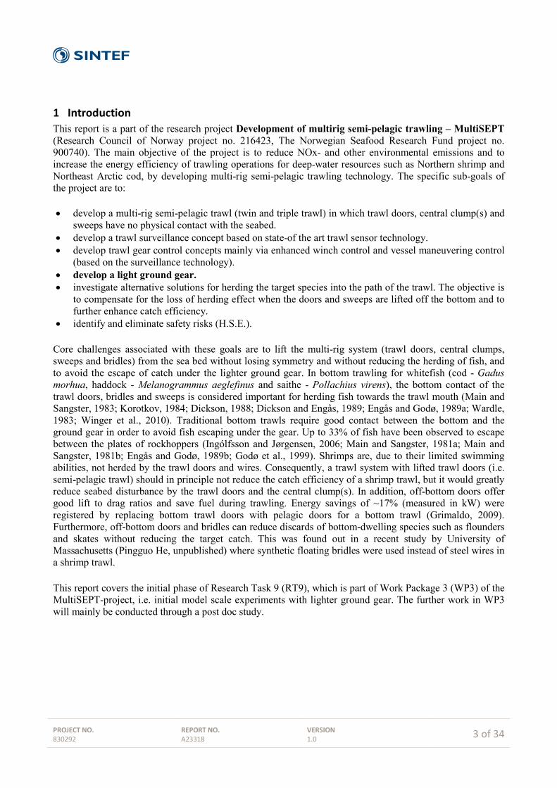
Figure 6. Model (Scale 1:4) of the Mørenot 440 Redline saithe trawl (left), set up with a traditional rockhopper gear (right, cf. Section 2.5.2).
2.5.2 Rockhopper (RH) The rockhopper gear was 25 m long (five sections of 3.5 m + 6 m + 6 m + 6 m and 3.5 m respectively), with 21" (~530 mm) rubber discs, 400 mm spacing in the side sections, 200 mm spacing in the center (6 m) section, 19 mm (6.5 kg/m) long-link center chain, 13 mm (2.7 kg/m) long-link guide chain (Figure 6).
2.5.3 Brush gear (B) The brush gear is basically a rockhopper gear with brushes ("road brooms") between the rockhopper discs; the brush sections fill in the openings between the discs and thereby reduce escapement. The planned model tests with brush gear were abandoned (cf. Section 2.1), but brush gear may still be tested in later full scale trials during the project.
Figure 7. Example of a brush gear.

PROJECT NO. 830292
REPORT NO. A23318
VERSION 1.0
12 of 34
2.5.4 Skirt (S) In cases 2a-2b, the center rockhopper section was replaced by a 6 m skirt section with bottom chain weighing 4 kg/m, (Figure 8 and Figure 9). In Cases 2a-2b the upper and lower line of the skirt section had equal length. In cases 4a-4b the entire rockhopper gear was replaced by a skirt composed of 5 sections with 1 m overlapings, the center section here being 12 m (Figure 10). All skirt sections had bottom chains weighing 4kg/m (double weight in the overlapings). In this case the upper line was 26.25 m long and the bottom line 26 m, measured between the butterflies, i.e. 1 % shorter along the bottom yielding a forward tightened skirt as seen in Figure 10 and Figure 11. In addition, 9 floats with a total buoyancy of 38 kg were attached to the fishing line at the center section in order to maintain the height of the fishing line and the skirt. In both cases the skirt was 560 mm high and built in square meshed netting with a mesh size of 150 mm (full scale values).
Figure 8. Center rockhopper section replaced by a traditional square meshed skirt (cases 2a-2b).
Figure 9. Skirt section with a bottom chain.

PROJECT NO. 830292
REPORT NO. A23318
VERSION 1.0
13 of 34
Figure 10. Full skirt with 1 m overlapings (cases 4a-4b). Note the similarity between the top right picture and Figure 11 regarding the shortened bottom line.
Figure 11. Picture of a slightly inclined bottom skirt due to shortened bottom line (Photo: Institute of Marine Research, Bergen).

PROJECT NO. 830292
REPORT NO. A23318
VERSION 1.0
14 of 34
2.5.5 Modified skirt (MS1 and MS2) Two versions of a modified skirt were tested:
• In MS1 (cases 4c-4h) the skirt consisted of 3 sections with approximately 1 m overlapings. The center section was 12 m long and was composed by diamond meshes mounted to an elastic bottom rope. The hanging ratio of the diamond meshed section was approximately 0.5. The two shorter side sections had square meshes and a traditional non-elastic bottom rope. The diamond meshes and the elastic rope allowed the center section to stretch when it encountered an obstacle (Figure 12), (square meshes have no geometrical elasticity, while a diamond mesh can stretch and narrow when it is subject to tension). The elastic bottom rope had an upstretched length of 11.60 m (2.90 m in model scale), while the upper line was 12 m (3.0 m in model scale), i.e. the elastic bottom rope was 3 % shorter. We do not have an exact measure of the elasticity of the rope, but elongation tests with known weights gave an elasticity in model scale of approximately 230 N/m, i.e. 2.3 kg/m. From TBC in Table 4 we see that the average full scale tension in the bottom chain was of the order 100 kg, i.e. 100/64 ≈ 1.6 kg in model scale, and that the maximum tension was up to 2.6 times larger, i.e. up to approximately 4 kg in model scale. Hence the elasticity of the rope would allow it to stretch by up to approximately 1.75 m in model scale, which implies a 15 % elongation of the elastic 12 m section. The side sections had a 4 kg/m bottom chain. The center sections had the same type of bottom chain, but in this sections it was mounted with a slack to the elastic rope in order to allow sufficient stretching, see Figure 12. Hence the chain weight per meter was somewhat higher for this section.
• MS2 (cases 4i-4m) was identical to MS1, except that the elastic rope was replaced by an ordinary
non-elastic rope with length 11.84 m (2.96 m in scale model), i.e. 1 % shorter than the upper line (similar to cases 4a-4b).
Figure 12. Diamond mesh skirt section with elastic bottom rope and bottom chain mounted with slack.

PROJECT NO. 830292
REPORT NO. A23318
VERSION 1.0
15 of 34
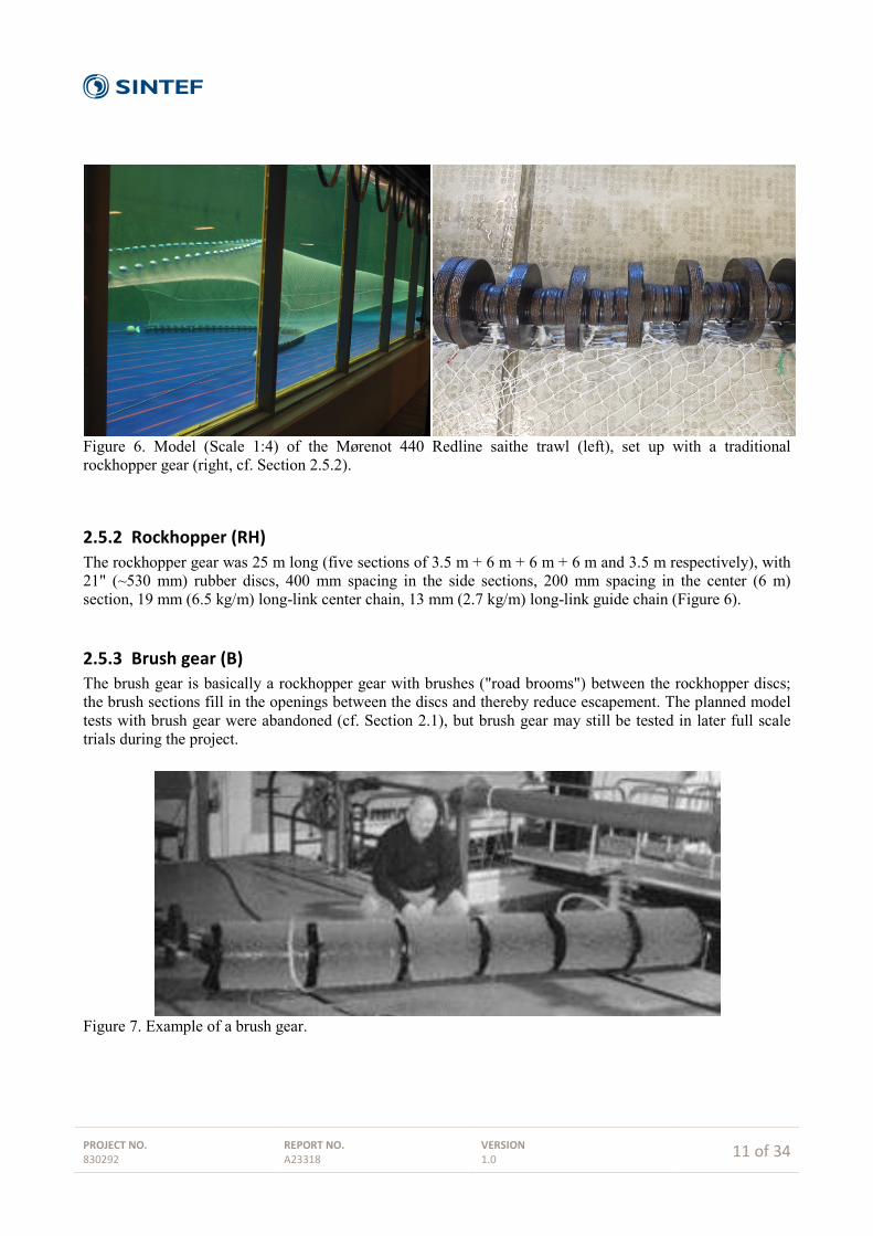
2.5.6 Modified plate gear (MP1 and MP2) The so-called spreading ground gear or plate gear (Valdemarsen and Hansen, 2007) was developed as an alternative to the rockhopper gear, in order to increase the spread of the ground gear and to reduce weight, resistance and escapement of catch. The plate gear was found to work well in sea trials, but it has not yet found widespread commercial use, potentially because it can be difficult to adjust optimally. In an internal workshop at SINTEF Fisheries and Aquaculture in October 2011, two alternative riggings of the rectangular plates in the plate gear were proposed. These riggings are the basis for MP1 and MP2 in this report. In addition, a gear based on plates with an L-shaped profile and a simpler rigging were proposed in the workshop. It was difficult to find a way to manufacture these L-profiles at a reasonable cost for the planned tests in this project, and this concept was therefore not tested. However, the semi-circular spreading gear (SCSG1 and SCSG2) described in Section 2.5.7 resembles the "L-profile" gear, but with a semi-circular profile and a slightly different rigging of the gear chain. The MP1 gear (cases 5a-5f) was made from 35 rubber plates with dimensions 540x500x80 mm (WxHxT, full scale values). Initially, the plates were attached to the fishing line using the four chains on the rear side of the plate (Figure 13 and Figure 15). In this way the plates were able to move independently of each other. The spacing between the plates was defined by the number of chain links in the fishing line between the attachment points of two neighboring plates. This distance was 800 mm (full scale value). Because the width of the plates was 540 mm, the average spacing between two plates was 260 mm (i.e. approx. B/2). However, the fact that the plates are positioned in front of the fishing line means that the actual distance between the plates is smaller, but we do not have an exact measure of this distance. Figure 13 and Figure 15A, B and C show how the individual plates were connected to the gear chain, which was running in front of the plates, by a double set of backstrops/crowfeet. The gear chain was a 25 m long 19 mm long link chain. The gear chain was attached the lower end of the Danleno triangle, and the fishing line was attached to the upper end. The higher tension in the gear chain compared to the fishing line will turn the triangle from the upright position. Although this initial MP1 rigging was dynamically stable, Figure 15F shows that it allowed too large distance between the plates and the fishing line near the wings, while in the center many of the rear chains were slack (Figure 15D-E). It may be possible to improve this rigging by adjusting the chain lengths on each plate individually, but this was considered both unpractical and unnecessary. Instead, as suggested in the SINTEF workshop, the rear chain system could be removed and the plate joined directly to the fishing line from its two upper corners. In order to save time for the tests, the rear chains were not physically removed from all plates in the gear. Only the plates in the center section were modified according to Figure 14, while for the plates in the side sections the rear chain system was "short circuited" by attaching the second chain link on the two upper rear chains to the fishing line using plastic bundle strips. This can be seen in Figure 16A-C. It should be noted that the chain rigging of the center and side plates were physically equivalent, and that the slack chains hanging behind the plates in the side sections had no influence on the system or on the measurements. This constitutes the final MP1for which tension was measured. MP2 (cases 5g-5m) (see Figure 17) is in principle similar to MP1. The difference is that in MP2, 3 more plates were inserted in the center section of the gear, yielding very little (practically zero) space between the plates in this section (see Figure 18 also). Both versions of the modified plate gear (MP1 and MP2) got easily stuck in the bottom obstacles tested, likely due to the gear chain lying ahead of the plates. Therefore, in order to try to mimic some of the properties and behavior of a rockhopper gear, in cases 5l-5m the gear chain at the center section were filled with 200 mm rockhopper disks/spacers (full scale dimensions; 50 mm diameter in model scale) (see Figure 18).

PROJECT NO. 830292
REPORT NO. A23318
VERSION 1.0
16 of 34
Figure 13. Sketch of initial rigging of the plates in MP1.
Seen from aft ( back ) side
Upper chains: 648 mmLower chains 792 mm
Seen from sidefront V connected togear chain
aft V connected toFishing line
Seen from front
Length of 4 chains connected to gear chain
432 mm

PROJECT NO. 830292
REPORT NO. A23318
VERSION 1.0
17 of 34
Figure 14. Sketch of final rigging of the plates in the modified plate gear MP1 and MP2 (cases 5a-5f).
Seen from aft ( back ) side
Upper chains: 216 mm
Seen from sidefront V connected togear chain
upper chain connected toFishing line
Seen from front
Length of 4 chains connected to gear chain
432 mm

PROJECT NO. 830292
REPORT NO. A23318
VERSION 1.0
18 of 34
Figure 15. Pictures of the initial rigging of MP1 with the rear chain rigging to the fishing line.
A B
C D
FE
PROJECT NO. 830292
REPORT NO. A23318
VERSION 1.0
19 of 34
Figure 16. Final version of MP1. Note the slack chains on the rear side of the plates in the side sections (pictures A-C). Picture D shows the gear chain running ahead of the plates.
A
DC
B

PROJECT NO. 830292
REPORT NO. A23318
VERSION 1.0
20 of 34
Figure 17. Details of the rigging of the plates in the center section of MP2, cases 5g-5k.
Figure 18. Center section of the gear chain filled with 200 mm (full-scale dimension) spacers in MP2, cases 5l- and 5m.

PROJECT NO. 830292
REPORT NO. A23318
VERSION 1.0
21 of 34
2.5.7 Semi-circular spreading gear (SCSG1 and SCSG2) The final gear type tested consisted of semi-circular profiles made out of a 160 mm (640 mm full scale) diameter PVC pipe. The profiles were 160 mm (640 mm full scale) wide. Two holes were drilled at the two upper corners, and two more at the edge and a small distance above the middle of the profile (the ratio of the semi-circle circumferential sector above and below the middle holes was approximately 40/60).
Figure 19. The sketch shows the specifications and mounting of SCSG 1.
In SCSG1 (cases 12a-12f) the profiles were attached directly to the fishing line using plastic bundle strips through the two holes in the top corners (Figure 19 and Figure 20). On the starboard half side of the gear the plates were mounted with their top edge just below the fishing line, while on the port side they were mounted with their top edge just above the fishing line. The motivation for this was to see if this detail had any practical significance. The gear chain was attached to the profile by plastic bundle strips through the middle holes, with the gear chain behind (i.e. on the rear side of) the profiles (see Figure 21, bottom left and right). In this way the gear chain is protected from direct contact with bottom obstacles. The spacing between the plates was approximately 25 mm (100 mm full scale).

PROJECT NO. 830292
REPORT NO. A23318
VERSION 1.0
22 of 34
Figure 20. The SCSG1 with semi-circular profiles and a simple mounting and rigging.
In SCSG2, the gear chain and the fishing line were combined into one line, and the semi-circular profiles were attached to this line by plastic bundle strips through the middle-holes of the profiles (i.e. similar to the gear chain in SCSG1) (see Figure 21). This combined line was attached to the triangular butterfly by a backstrop/crowfoot. The top end of the profile was free, i.e. not attached to any line or netting, and lay below the net. Hence, the profile was prevented from tilting in one direction but it could still tilt in the other direction, as illustrated seen during the setting process (bottom left picture in Figure 21). Most of the profiles turned easily in the right direction once the trawl was set, but some profiles maintained an incorrect tilt (as seen for some of the plates on the starboard side in the background right picture in Figure 21). Due to these problems no measurements were made for SCSG2. Some of the problems may be resolved by fixing also the top end e.g. to the netting, but this would most probably affect the geometry of the netting. The main advantage of SCSG2 would be the simplicity of having only one bottom line (i.e. a combined gear chain and fishing line).

PROJECT NO. 830292
REPORT NO. A23318
VERSION 1.0
23 of 34
Figure 21. SCSG 2 with combined fishing line and gear chain. In this case the top end of the profiles lay free below the net. The picture to the left was taken during setting while the picture to the right was taken during towing.

PROJECT NO. 830292
REPORT NO. A23318
VERSION 1.0
24 of 34
3 Results
3.1 Tabulated summary of results The experiments were carried out in two separate periods in 2012 (week 21 and week 27, see Table 1) and the results are presented and discussed accordingly. The main objective of the tests was to measure tension (towing resistance) in the different tested cases. Therefore, emphasis was put on maintaining constant overall trawl geometry, i.e. on keeping the spread, headline height and wing-end height equal, so that the different cases were as comparable as possible. However, as explained below, we used a different spread in week 27 than in week 21. The maximum flow velocity in the tank is limited to approx. 1 m/s, and the corresponding maximum full-scale velocity is determined by the model scale according to Section 2.2. Due to the large model scale (1:4) the highest achievable full-scale velocity was 3.0 knots. Most tests were done with this velocity, but some velocity variations were included in week 21. In the tests in week 21, the largest possible distance between the fixed tow points (dTP = 31.2 m) was chosen for most of the experiments, because this gave the highest spread between the Danlenos (dBF = 18.4 m). Thus, case 1e was chosen as the reference case for the tests in week 21, cf. Table 4. In the tests with the modified plate gears (week 27) we achieved a spread of dBF = 16 m for dTP = 29.6 m, i.e. similar to Case 1a-c. However, increasing dTP to 31.2 m did not result in an increased value of dBF for the modified plate gears. We therefore chose to use dTP = 29.6 m for all tests in week 27, and used case 1c in Table 4 as the reference case for these tests (Table 5). The results for the tests carried out in week 21 and 27 are summarized in Table 4 and Table 5, respectively. The nomenclature is given in Table 3:
- The quantities and results with subscript 'max' refer to the cases with a bottom obstacle, showing the maximum tension measured when the gear is being retained by the obstacle.
- The quantities with subscript '1e' or '1c' denote values relative to the corresponding quantities for case 1e (used as reference case in Table 4) or case 1c (used as reference case in Table 5), i.e. using the full rockhopper gear at 3.0 knots as a reference case.
- Empty fields imply that the given quantity was not measured for the specific case.

PROJECT NO. 830292
REPORT NO. A23318
VERSION 1.0
25 of 34
Table 3. Nomenclature for Table 4 and Table 5.
Denomination / symbol Description/Definition Dimension Case Configuration number according to Tables 1 and 3 - Side Bottom gear type in the side sections / wings - Center Bottom gear type in center section - V Nominal flow (towing) velocity knot (1 knot = 0,514 m/s) dTP Distance between fixed tow points (port and starboard tow masts) m dBF Distance between Danlenos / butterflies m hHL Headline height above bottom m hWE Height of wing-ends above bottom m TLS Average tension in lower sweep (average port and stb side) kg THL Average tension in headline (average port and stb side) kg TFL Average tension in fishing line (average port and stb side) kg TRH Average tension in rockhopper main chain (average port and stb side) kg TBC Average tension in bottom chain of skirt (average port and stb side) kg TG Average tension in gear chain of skirt for MP1, MP2 and SCSG1 (average
port and stb side) (Table 5 only) kg
TLS,max Maximum value of TLS relative to average TLS - THL,max Maximum value of THL relative to average THL - TBC,max Maximum value of TBC relative to average TBC - TG,max Maximum value of TG relative to average TG (Table 5 only) - TFL,max Maximum value of TFL relative to average TFL (Table 5 only) - THL+LS,1e Sum of TLS + THL relative to Case 1e - TLS,1e TLS relative to Case 1e - THL,1e THL relative to Case 1e - Bottom obstacle - 10 or 20 kg cast iron conical weights (model scale weight; equals
640 and 1280 kg in full scale respectively), placed standing upright or lying down
- 60 kg: 30 kg welded steel structure with both cast iron weights (10 + 20 kg) fixed to it
- placed at the center line of tank except when denoted "1 m off", when the weight is placed 1 m to the side of the center line (1 m in model scale, 4 m in full scale)
-

PROJECT NO. 830292
REPORT NO. A23318
VERSION 1.0
26 of 34
Table 4. Results from tests in week 21; Case 1, 2, 4 and 4*, cf. Table 1 and Table 3. All values are given in full scale.
Case Side Center V d_TP d_BF h_HL h_WE T_LS T_HL T_FL T_RH T_BC T_LS_MAX T_HL_MAX T_BC_MAX T_LS+HL,1e T_LS,1e T_HL,1e Bottom obstacle
1a RH RH 2,5 29,6 16 7,2 4,2 882 808 310 538 - - - - 0,71 0,71 0,71 -1b RH RH 2,75 29,6 16 6,9 4 993 908 370 589 - - - - 0,8 0,8 0,8 -1c RH RH 3 29,6 16 6,6 4 1119 1017 432 650 - - - - 0,9 0,91 0,9 -1d RH RH 2,75 31,2 18,4 6,2 4 1103 1019 344 738 - - - - 0,9 0,89 0,9 -1e RH RH 3 31,2 18,4 6 4 1234 1135 379 833 - - - - 1 1 1 -
2a RH S 2,75 31,2 18,4 6,2 4 1090 931 - - - - - - 0,85 0,88 0,82 -2b RH S 3 31,2 18,4 6,2 4 1189 1040 - - - - - - 0,94 0,96 0,92 -
4a S S 2,75 31,2 18,4 6,2 4 739 1031 - - - - - - 0,75 0,6 0,91 -4b S S 3 31,2 18,4 6,2 4 842 1157 - - - - - - 0,84 0,68 1,02 -
4c S MS1 3 31,2 18,4 6,2 4 835 1163 - - 95 1,06 1,05 1,08 0,84 0,68 1,02 -4d S MS1 3 31,2 18,4 6,2 4 859 1173 - - 103 1,7 1,05 1,73 0,86 0,7 1,03 10 kg, upright4e S MS1 3 31,2 18,4 6,2 4 821 1173 - - 94 1,34 1,05 1,67 0,84 0,67 1,03 10 kg, lying4f S MS1 3 31,2 18,4 6,2 4 865 1170 - - 106 1,83 1,06 2 0,86 0,7 1,03 20 kg, upright4g S MS1 3 31,2 18,4 6,2 4 833 1168 - - 101 1,65 1,05 2,6 0,84 0,68 1,03 20 kg lying4h S MS1 3 31,2 18,4 6,2 4 827 1170 - - 97 1,67 1,05 1,79 0,84 0,67 1,03 20 kg upright,1 m off
4i S MS2 3 31,2 18,4 6,2 4 838 1165 - - 91 1,05 1,05 1,08 0,85 0,68 1,03 -4j S MS2 3 31,2 18,4 6,2 4 855 1169 - - 104 1,29 1,05 2,23 0,85 0,69 1,03 10 kg upright4k S MS2 3 31,2 18,4 6,2 4 804 1139 - - 87 1,36 1,09 1,9 0,82 0,65 1 10 kg lying4l S MS2 3 31,2 18,4 6,2 4 857 1169 - - 102 1,65 1,04 2,48 0,86 0,69 1,03 20 kg upright
4m S MS2 3 31,2 18,4 6,2 4 838 1167 - - 98 1,64 1,05 2,39 0,85 0,68 1,03 20 kg lying
1f RH RH 3 31,2 18,4 6,2 4 1224 1132 - - - 1,05 1,05 - 0,99 0,99 1 -1g RH RH 3 31,2 18,4 6,2 4 1420 1132 - - - 1,71 1,05 - 1,08 1,15 1 10 kg upright1h RH RH 3 31,2 18,4 6,2 4 1244 1129 - - - 1,25 1,05 - 1 1,01 0,99 10 kg lying1i RH RH 3 31,2 18,4 6,2 4 1461 1125 - - - 2,17 1,05 - 1,09 1,18 0,99 20 kg upright1j RH RH 3 31,2 18,4 6,2 4 1221 1126 - - - 1,5 1,05 - 0,99 0,99 0,99 20 kg lying1k RH RH 3 31,2 18,4 6,2 4 1360 1134 - - - 1,89 1,06 - 1,05 1,1 1 20 kg upright, 1m off

PROJECT NO. 830292
REPORT NO. A23318
VERSION 1.0
27 of 34
Table 5. Results from tests in week 27; Case 5, 5*and 12, cf. Table 1 and Table 3. All values are given in full scale.
Case Side Center V d_TP d_BF h_HL h_WE T_LS T_HL T_FL T_G T_LS_MAX T_HL_MAX T_G_MAX T_FL_MAX T_LS+HL,1c T_LS,1c T_HL,1c Bottom obstacle
5a MP1 MP1 3 29,6 16 6,6 4 1265 991 438 773 1,04 1,05 1,04 1,08 1,06 1,13 0,97 -5b MP1 MP1 3 29,6 16 6,6 4 1251 952 417 779 1,96 1,05 2,46 1,13 1,03 1,12 0,94 10 kg upright5c MP1 MP1 3 29,6 16 6,6 4 1210 957 417 740 1,24 1,04 1,37 1,08 1,01 1,08 0,94 10 kg lying5d MP1 MP1 3 29,6 16 6,6 4 1260 953 420 781 1,46 1,06 1,69 1,1 1,04 1,13 0,94 20 kg upright5e MP1 MP1 3 29,6 16 6,6 4 1237 958 425 758 1,32 1,04 1,49 1,06 1,03 1,11 0,94 20 kg lying5f MP1 MP1 3 29,6 16 6,6 4 1235 949 423 758 1,76 1,06 2,14 1,11 1,02 1,1 0,93 20 kg upright, 1m off
5g MP2 MP2 3 29,6 16 6,6 4 1186 955 417 718 1,58 1,05 1,9 1,11 1 1,06 0,94 60 kg5h MP2 MP2 3 29,6 16 6,6 4 1212 950 421 738 1,74 1,05 2,11 1,13 1,01 1,08 0,93 60 kg5i MP2 MP2 3 29,6 16 6,6 4 1265 961 426 786 1,24 1,06 1,41 1,09 1,04 1,13 0,94 60 kg5j MP2 MP2 3 29,6 16 6,6 4 1479 951 444 973 1,56 1,06 1,75 1,15 1,14 1,32 0,94 60 kg, 1 m off5k MP2 MP2 3 29,6 16 6,6 4 2033 958 440 1498 1,91 1,07 2,17 1,22 1,4 1,82 0,94 60 kg, 1 m off5l MP2 MP2 3 29,6 16 6,6 4 1443 949 378 994 1,87 1,04 2,15 1,16 1,12 1,29 0,93 60 kg, 1 m off
5m MP2 MP2 3 29,6 16 6,6 4 1626 945 395 1220 1,96 1,04 2,36 1,12 1,2 1,45 0,93 60 kg
12a SCSG1 SCSG1 3 29,6 17,4 6,6 4 1140 981 112 950 1,04 1,05 1,05 1,15 0,99 1,02 0,96 -12b SCSG1 SCSG1 3 29,6 17,4 6,6 4 1143 982 112 955 2,08 1,06 2,21 1,4 0,99 1,02 0,97 60 kg12c SCSG1 SCSG1 3 29,6 17,4 6,6 4 1274 984 121 1077 2,01 1,06 2,11 1,35 1,06 1,14 0,97 60 kg12d SCSG1 SCSG1 3 29,6 17,4 6,6 4 1214 987 124 1014 2,01 1,06 2,13 1,4 1,03 1,08 0,97 60 kg, 1 m off12e SCSG1 SCSG1 3 29,6 17,4 6,6 4 1194 989 123 1006 2,16 1,05 2,34 1,1 1,02 1,07 0,97 60 kg, 1 m off12f SCSG1 SCSG1 3 29,6 17,4 6,6 4 1190 991 124 994 1,85 1,05 1,97 1,29 1,02 1,06 0,97 60 kg, 1 m off

PROJECT NO. 830292
REPORT NO. A23318
VERSION 1.0
28 of 34
4 Discussion In Section 4.1, we discuss the main results for the average tension in the different lines in the different tested cases. In addition, variations with velocity and spread are also discussed in the cases where this is relevant. In Section 4.2, we discuss the main results for the maximum tension in the different lines. These maxima occur when the bottom gear encounters a bottom obstacle. Hence, they indicate not only the load increase and distribution as a bottom gear encounters and possibly gets stuck in a bottom obstacle, but they also indicate how easily a specific gear might pass a similar size obstacle. Although the geometry of the obstacles used in these tests are "arbitrarily" chosen, they are considered realistic representations of seabed obstacles.
4.1 Average tension in lower sweep, headline, fishing line and gear chains
4.1.1 Week 21, Table 4
- Cases 1a-c show that when increasing the towing velocity from 2.5 to 2.75 and 3.0 knots for a rockhopper gear and dTP = 29.6 m, the average tensions increase correspondingly, and the tension increases more or less equally in the headline and in the lower sweeps. The spread is not affected, the wing-end height is somewhat reduced, while the headline height is markedly reduced with increasing velocity. The same general results are found for cases 1d-e, 2a-b and 4a-b. The results indicate that increasing the velocity primarily affects geometry and secondarily the distribution of forces.
- Cases 1a-e further show that the tension in the rockhopper chain TRH is generally higher than in the
fishing line TFL. However, comparing cases 1d-e with cases 1a-c, we also see that when the spread dBF is increased, TFL is reduced while TRH is increased. Hence the ratio TRH/TFL increases with increasing spread for a rockhopper gear.
- Cases 1f-k are identical to Case 1e, and were carried out in order to have results with bottom
obstacles for the rockhopper gear also. Case 1f was run without a bottom obstacle and is therefore equivalent to Case 1e, and we see that the measured tensions are equal in both cases. In Case 1g-k we see that the average tensions are slightly higher than in cases 1e and 1f. The reason for this is that bottom obstacles were retained by the gear for a certain period and did not pass under the gear right after reaching the maximum tension.
- Regarding the distribution of tension between the lower sweep and the headline, we see that for the reference rockhopper gear in Case 1e, the average tension in the lower sweep (TLS) is approximately 8 % higher than in the headline (THL). For all cases with a full skirt on the other hand, i.e. cases 4a-m, the average tension in the lower sweep TLS is roughly 25 % lower than in the headline THL.
- Case 2b shows that when replacing the center section in a rockhopper gear with a skirt section, the total average tension is reduced by 6 % (TLS+HL,1e = 0.94). In this case the reduction is relatively larger in the headline than in the lower sweep. This is contrary to the results for the cases with a full skirt (see next bullet point), and we have not found an explanation for this discrepancy.
- Cases 4b, 4c, and 4i show that the average tension in the headline in the cases with full skirts is the
same as in Case 1e (cf. THL,1e), while the tension in the lower sweep 32 % lower in these cases

PROJECT NO. 830292
REPORT NO. A23318
VERSION 1.0
29 of 34
compared to the reference rockhopper gear (cf. TLS,1e). The total average tension TLS+HL,1e at the fixed tow points is thus reduced by roughly 15 % by replacing a full rockhopper gear with a full skirt.
- Case 4c and 4i show that for a full skirt, the tension in the bottom chain TBC is less than 10 % of the
overall tension TLS in the lower sweep. Although the placement of the load cell was such that not all the tension in the bottom chain would be covered by this measurement (see Section 2.3), this indicates that the tension in the fishing line can be considerably higher for the case with a full skirt compared to the case with a full rockhopper gear (where the fishing line is relieved by the rockhopper chain). This suggests that the fishing line may be more subject to strain and elongation in case of a full skirt.
- Cases 4d-h, 4j-m and 1g-k pertain to bottom obstacles and maximum loads and are discussed in
Section 4.2.
4.1.2 Week 27, Table 5
- Case 5a shows that the total average tension for the modified plate gear MP1 is 6 % higher (TLS+hl,1c = 1.06) than for the reference rockhopper gear in case 1c. The increase takes place in the lower sweep (TLS,1c = 1.13), more specifically in the gear chain (TG), while the tension in the headline is slightly reduced (THL,1c = 0.97). The tension in the fishing line is generally lower than in the gear chain, and there is only a modest increase in the tension in the fishing line.
- The distance between the Danlenos was not higher for any of the modified plate gears MP1 or MP2 than for the rockhopper or skirts tested in week 21. Hence, the modified plate gears tested did not show the additional spreading effect associated with the original plate gear.
- No measurements were made without bottom obstacle for MP2. Hence, average tensions for MP2 are not considered here.
- Case 12a shows that the total average tension in the semi-circular spreading gear (SCSG1) proposed
here is very similar to the corresponding rockhopper gear in Case 1c (TLS+HL,1c = 0.99), and that the distribution between the headline and the lower sweep is also very similar to the rockhopper gear (THL,1c = 0.96, TLS = 1.02). However, for SCSG1, most of the tension in the lower sweep comes from the gear chain, and only approximately 12 % from the fishing line
- Case 12a also shows that SCSG1 provided considerable additional spreading; dBF is 1.4 m (9 %)
higher for case 12a than for case 5a and case 1c. Hence, although the tension is comparable to the reference rockhopper gear, the additional spread implies a reduced overall drag coefficient for the trawl with the SCSG1 gear.
- Cases 5b-f, 5g-5m and 12a-12f pertain to bottom obstacles and maximum loads and are considered
in Section 4.2.

PROJECT NO. 830292
REPORT NO. A23318
VERSION 1.0
30 of 34
4.2 Maximum tension in in lower sweep, headline, fishing line and gear chains when the bottom gear is retained by a bottom obstacle
4.2.1 Week 21, Table 4
- The duration of the period the bottom obstacle is retained by the gear is limited compared to the total duration of the time series run for each case. Therefore the duration of this maxima period has a limited influence on the average tension values calculated. Considering the values in the columns TLS+HL,1e , TLS,1e and THL,1e for the cases with bottom obstacles, we see that it is only in cases 1g and 1h in Table 4 that the maxima has a significant influence on the average values.
- When a bottom obstacle is retained by the bottom gear, all increase in tension takes place in the lower sweeps. There is no significant increase in the tension in the headline in any of the cases, not even in the cases with the most severe increase in tension in the lowers sweep, i.e. THL,max = 1.04-1.09 in all cases.
- The maximum tension in the lower sweep is increased by up to 83 % for the cases with a full skirt
(Cases 4c-m: TLS,max = 1.83 in case 4f), and by up to 117 % for the rockhopper gear (Cases 1f-k: TLS,max = 2.17 in case 1i). The maximum tension in the lower sweeps is generally higher for the full rockhopper gear than for the full skirt, and the relative increase is also higher.
- There is no clear difference between the maximum tension in the lower sweeps between the cases
with MS1 (skirt with elastic bottom rope) and MS2 (skirt with inelastic bottom rope), for the cases with equivalent bottom obstacles, i.e. when comparing TLS,max in case 4d with case 4j etc.. For the bottom chain however, the maximum tension TBC,max is in most cases higher for MS2 than for MS1, for equivalent bottom obstacles. This indicates that the elastic bottom rope helps MS1 pass bottom obstacles more easily. This was also the impression from the visual observations during the tests. However, the highest increase in tension in the bottom chain is for MS1, with an increase of 160% (TBC,max = 2.6 in case 4g). The elasticity of the skirt is not decisive, i.e. the elastic bottom rope can be quite elastic, as long as it maintains the tightened shape in normal operation (Figure 11), and as long as its ultimate breaking load is sufficient with regard to the expected maximum loads in the bottom line of the skirt.
- The results for TLS, max in cases 4c-4m and 1f-k show that the maximum tension is lowest for the 10
kg weight lying down and highest for the 20 kg weight standing upright. Hence, the measured tension increase is in accordance with what one would physically expect from the weight, height and shape of the bottom obstacles (cf. Figure 2 and Table 2), indicating that such tests do provide much additional useful information.
- For the rockhopper gear and the skirts, i.e. Cases 4c-4m and 1f-k, the maximum tension is lower in
the cases with the bottom obstacle placed 1 m to the side of the center line than in the case with the weight at the center line (Case 4h vs. 4f and case 1k vs. 1i). This indicates that the gear passes an obstacle easier at the sides than at the center, and that a more tapered (V-shaped) bottom gear might pass bottom obstacles more easily.

PROJECT NO. 830292
REPORT NO. A23318
VERSION 1.0
31 of 34
4.2.2 Week 27, Table 5
- As discussed in Section 4.2.1, the periods of maxima had a limited influence on the average tension values calculated for the different cases. However, the modified plate gears got stuck in the bottom obstacles more easily than the rest of the gears tested and the duration of retainment was relatively longer. This is reflected in the values for TLS,1c in Table 5, Case 5j-m, in particular.
- Also, as described in Section 4.2.1, all increase in tension due to bottom obstacles took place in the lower sweeps, with no significant increase in the tension in the headline in any of the cases, i.e. THL,max = 1.04-1.07 in all cases.
- The maximum tension in the lower sweep is increased by up to 96 % for the modified plate gears
(Case 5a-m: TLS,max = 1.96 in cases 5b and 5m), and by up to 116 % for the SCSG1 gear (Case 12a-f: TLS,max = 2.16 in Case 12e). However, one must here recall that the maximum values are given relative to the average values. For cases 5j-m, where the maxima influence the average values significantly, one must account for this. For example, for case 5k the maximum may more correctly be estimated to 1.91·1.82 = 3.48 (248 %). Then the maximum tension in the MP2 gear (Cases 5g-m) can be seen to be considerably higher than for the SCSG1 gear (Case 12a-f). The MP2 and SCSG1 gears cannot be directly compared to the rockhopper gear (cases 1f-k), because different bottom obstacles are used. However, the maximum tension in the lower sweeps for the MP1 gear (Cases 5a-f) can be seen to be comparable to the rockhopper gear (Cases 1f-k) for the same types of bottom obstacles.
- As stated in Section 4.1.2, the tension in the lower sweeps primarily comes from the gear chain in all
cases for the modified plate gears and the SCSG1 gear. Further, the increase primarily takes place in the gear chain. There is only a modest increase in tension in the fishing line when the gears are retained by a bottom obstacle, even for the most severe cases.
- The SCSG1 gear was observed visually to pass the bottom obstacles easily in most cases, but it also
got stuck in some cases. The height of the profiles, i.e. the height of the fishing line above the bottom and the height of the gear chain above the bottom, are important factors for its ability to pass bottom obstacles, as is the she spacing between the profiles.
- No particular difference was found between the cases where the 60 kg bottom obstacle was placed at
the center line and the cases where the 60 kg bottom obstacle was placed to the side of the centreline.

PROJECT NO. 830292
REPORT NO. A23318
VERSION 1.0
32 of 34
5 Summary of results and conclusions - The model scale tests suggest that changing the towing velocity primarily affects the overall trawl
geometry and forces, and only secondarily the relative distribution of tension between the different lines and chains. i.e. the relative distribution of tension is first affected when there are large changes in geometry.
- For a rockhopper gear, the ratio between the tension in the rockhopper chain and the fishing line (TRH/TFL) increases with increasing spread.
- For the specific model trawl tested (Mørenot 440 Saithe trawl), when rigged with a traditional
rockhopper gear, the tension in the lower sweeps were 8 % higher than the tension in the headline.
- When the entire rockhopper was replaced by a skirt, the tension in the headline remained unchanged while the tension in the lowers sweeps was reduced by 32 %. The tension in the lower sweeps then was 25 % lower than the tension in the headline, and the total towing resistance was reduced by 15 % compared to the rockhopper case.
- Replacing only the center section of the rockhopper with a skirt section reduced the total towing
resistance by 6 %.
- For the cases with a full skirt, the tension in the bottom chain was less than 10 % of the total tension in the lower sweeps. Most of the tension then lies in the fishing line, hence the fishing line of a bottom trawl rigged with a skirt may be subject to considerably more strain than in a trawl rigged with a rockhopper gear. A diamond meshed skirt with an elastic bottom rope passed the bottom obstacles more easily than a traditional square meshed skirt with non-elastic bottom rope. The elasticity of the skirt does not appear to be decisive, i.e. the elastic bottom rope can be quite elastic, as long as it maintains an appropriate form normal operation, and as long as its ultimate breaking loads is sufficient compared to the expected maximum load.
- For the rockhopper gear and the modified plate gears, the tension in the fishing line was less than the
tension in the rockhopper/gear chain. The total tension (i.e. towing resistance) was higher for the modified plate gears, but the spread between the Danlenos was decreased rather than increased by the modified plate gear compared to the rockhopper gear. However, the modified plate gear was dynamically stable. Therefore, although the modified plate gears tested in these experiments cannot be concluded to be satisfactory, some elements from the modified plate gears may help improve the original plate gear rigging.
- The semi-circular spreading gear, in the SCSG1-version, showed very promising properties and
behaviour. The measured tensions and towing resistance was comparable to a rockhopper gear, but the new gear provided nearly 10 % higher spread and appeared to pass bottom obstacles more easily. Also, a greater portion of the tension in the lower sweeps came from the gear chain and only 12 % from the fishing line.
- When the bottom gear encountered and got stuck in a bottom obstacle, the entire increase in tension
took place in the lower sweep, for all gear types. The measured maximum tension was up to 2-3 times higher than the average tension. The increase tended to be higher for the rockhopper gear and the modified plate gears than for the skirts and the semi-circular spreading gear, reflecting that the latter two gears tended to pass the bottom obstacles more easily. The spacing between the profiles as well as the height of the profiles, (the height of the fishing line above the bottom and the height of the gear chain above the bottom) are important factor for the ability of SCSG1to pass bottom obstacles.

PROJECT NO. 830292
REPORT NO. A23318
VERSION 1.0
33 of 34
- In most cases the maximum tension was lower when a specific bottom obstacle was placed to the side of the center-line than when placed at the center-line. This suggests that a V-shaped or elastic/flexible skirts may pass bottom obstacles more easily.
- Summing up the distribution of tension between the fishing line and the gear chain, it can be
concluded that: o for the rockhopper gear and for the modified plate gears the tension in the fishing line is
somewhat lower (~50%) of the tension in the gear chain. o for the semi-circular spreading gear (SCSG1) the tension in the fishing line is much lower
than in the gear chain o for the skirts most of the tension goes in the fishing line and only a small portion in the
bottom chain. o When stuck in a bottom obstacle most, of the tension increase in the ground gear takes place
in the gear chain: The skirt, where the main increase is in the fishing line (although with a strong relative increase in the bottom chain also), is an exception to this.
- The tests indicate that the towing resistance (excl. doors and warps) can be reduced by 15 % by
replacing the rockhopper with a skirt. The main challenges with a skirt are to avoid damage when towing over rough bottom conditions, and to avoid loss of catch if a longer part of the skirt loses bottom contact. Using a more elastic/flexible skirt may help reduce such problems. A skirt consisting of several overlaping but separate sections may further reduce these problems, but may also be more difficult to rig and to obtain the desired tightened shape.
- Although the total towing resistance of the semi-circular spreading gear SCSG1 presented here is
comparable to the rockhopper gear, it must be noted both that the spread and thus the trawl area is also increased by the use of SCSG1. In addition, it must be recalled that the model tests are conducted on a perfectly even bottom with very little bottom friction, and that it is mainly the hydrodynamic resistance of the bottom gear that is included in such tests. Assuming that the semi-circular spreading gear slides more easily over rough bottom, and is less prone to dig into soft bottoms, the resulting operational towing resistance can be considerably lower than for a rockhopper gear. This is important to keep in mind for any gear, i.e. to consider also how they will run on a real bottom and to which extent they tend to dig into or ride above a soft bottom.

PROJECT NO. 830292
REPORT NO. A23318
VERSION 1.0
34 of 34
6 References Engås, A. and O.R. Godø. 1989a. The effect of different sweep lengths on the length composition of bottom-sampling trawl catches.
J. Cons. Int. Explor. Mer 45:263-268. Engås, A. and O.R. Godø. 1989b. Escape of fish under the fishing line of a Norwegian sampling trawl and its influence on survey
results. J. Cons. Int. Explor. Mer 45:269-276. Dickson, W.,1988. Size selectivity of trawl gear in arctic surveys. ICES CM 1988/B:20. Dickson, W., and Engås, A., 1989. Change in length composition of different species with the doors and sweeps on and off bottom.
ICES FTFB Working Group meeting, Dublin, April 24-26 1989. Grimaldo, E. 2009. Vurdering av energiforbruk i seitråling – underlag til IFU kontrakt mellom Nordnes AS, Egersund Herøy AS og
Innovasjon Norge. SINTEF Rapport SFH80 F093061. Godø, O.R., Walsh, S.J., and Engås, A., 1999. Investigating density-dependent catchability in bottom-trawl surveys. ICES J. Mar.
Sci., 56, 292-298. Ingólfsson, Ó. A., and Jørgensen, T., 2006. Escapement of gadoid fish beneath a commercial bottom trawl: relevance to the overall
selectivity. Fisheries Research, 79(3), 303-312. Korotkov, V.K., 1984. Fish behavior in a catching zone and influence of bottom trawl rig elements on selectivity. ICES CM
1984/B:15. Main, J. Sangster, G.I. 1981a. A study of the fish capture process in a bottom trawl by direct observations from a towed underwater
vehicle. Scott. Fish. Rep. 23:1–23. Main, J., Sangster, G.I., 1981b. A study of the sand clouds produced by trawl boards and their possible effect on fish capture. Scott.
Fish. Res. Rep. 20:1-20. Main, J., and Sangster, G.I., 1983. Fish reaction to trawl – a study comparing light and heavy ground gear. Scott. Fish. Res. Rep. 27. Valdemarsen, J.W, and Hansen, K., 2007. Kommersialisering av komponenter for ny type torsketrål, Rapport fra Havforskningen nr.
11-2007, Institute of Marine Research, Bergen, 2007. Wardle C.S., 1983. Fish reaction to towed fishing gears. In MacDonald A.G. and Priede I.G. (Eds.). Experimental Biology at Sea Winger, P.D., Eayrs, S., and Glass, C.W. 2010. Fish behaviour near bottom trawls. In: Behavior of Marine Fishes: Capture
Processes and Conservation Challenges. Edited by P. He. Blackwell Publishing. pp. 67-103.

Technology for a better society www.sintef.no