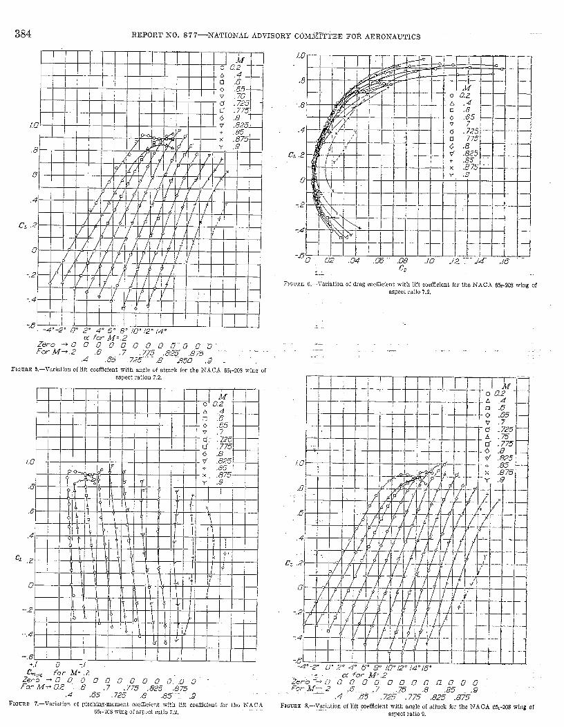
Embed Size (px)
Citation preview

REPORT NO. 877
SUNL%MRY REPORT ON THE HIGH-SPEED CIZARAC’I’EMSTICS OF SIX NIODEL WINGSHAWING NACA 65,-SERIES SECTIONS
BY WILLIAM T. HAMILTON AXD WARREX H. NELSON
SUXI}IARY
.-l Swnmay of & rtwdts ofu<nd-tun.nei tt!sk to determinethe high-speed a(rodynaraic characteristks of ~ix model wing~hating .N.4C.-I (Ml-series sections is presented in this report.T& 8-p(rcent-th ick wings wre superior to the l&percen fand I%pcrcent-fh it): u“ings -from the ~tandpoinf of powereconomy during [ezyl jlight jijr Mach numbers almre 0.76.Hwxcer, airplanes that are. t%j?y at Mzch numbers below 0.76will gain acrociyna in~ca/ly ljf f~~ perwnfage fhicknes.s ofthwing ancl th< aspect ratio are both increased. The lift-curredopes for f]L~ 8-ptrcent-{hick wings at 0.85 Mach number wereroughly twice their low+peed ralues. The t~ediwness qf a2W-percent-chord $ap on the 651-210 wing of aspect ratio 9decreased rapidly as the Mach number was raised abtiw 0.85i~idicating probable ciificulty in maintaining control by nwansof a 2(1-p~rcenf-chord Yap OB a t~<ng or tail of fhis thicknessat these Mach numbers. D;w-recor[ry jfap.s tesfed on the 8-percent-th ic?i wing of aspect ratio 7.2 reached the n-iaximurneJectireness at about (1.t?~Mach number.
INTRODUCTION
l’he high-speed ~erodynam”c characteristics of six thin,finite-span Kings having A-A.CA 65il-series airfoti sections aresummarized and compared in this report. The Klgh-speeclcharacteristics were obtained from tests rnacle in the Ames16-foot L@-speed wind tunnel- The tests were made toobtain data to aid in the design of airplanes hating highk~-el-fIi@ speeds.
lIODELS AN) APPARATUS
~he models were desig~ed and constructed at the AmesAeronautic] Laboratory. The cknensions of the modelsare shown in figure 1, find the coordinates of the variouswing sections are tablulated in table I. Figures 2 and 3 arephotographs showing one of the zgocIel win=gs mounted inth? Ames 16-foot high-speed wird tunnel. AU the wingshafl h-.\C.\ 651-series sections, 2.5 to 1 taper ratio, 3° dihe-draI, awl a 10-foot. span. The airfoil sections M had 0.2ideal lift coet%cient. rmcl a uniform chordwise Ioacl clistribu-tion (a= 1) at this lift coefficient. The W@ plan formswere such that the H-percent-chord lines were unswept.
All of the wings txcept the 651-?0S wing of aspect ratio9 ancI 65,-212 wing of aspect ratio 10.S hacl steel spars withcontoured 31asonite coverings. The 651-208 wing of aspectratio 9 was contoured from solid steel and the 651-212 wingof aspect ratio 10S had a steel spar with a contoured cover-
ing of “ cerrobase” rnetcd. The aft portion of the un~wis~ed _65+?10 fig of aspect. ratio 9 was a 0.20-chord, aluminum,hinged flap with & radius nose.
A taiI sting was attached to each wing for tests of the wingalone. .4 represent riti-re model bomber fuselage coT-Preci t&e __sting during the tests of the winogs ha~”ing cm aspect ratio 9when the chord-i-rise pressure distributions mere measured,The fuselage was so placed that the -wing incidence was 2°.reIative to the fuselage deck line.
The models were supported in the wincl tunnel by four 5-percent-thick front struts rmd one 7-percent-thick rear strut.
,,‘1 ,,’., 7. ..’
l,-.. _~------________:______________ +,7----___...- ___________________— -----
All di?nens@s Ih feet
1Section J$~i be. c. ‘ c’,
+
MA c z Rem@s
,— —
65L-23S ~. ~ 13. SS3 L!X4 o.’~4 L 475 z 05Ri-m 9 11.111 L 5S7 . E% L 180 !2.1565-210 9 lL 111 L .5-S7 .635 L 1S41 23% c flap.Li5~-210 ‘ Q q- 111 1.537 .635 1. la ~g ~ Y’ wash-out.65-212 9 H-111 L 5S7 . &35 LEW ~, 156&212 m s 9, ~g 1. 3B 5:% .!7s3 2.21 [“
..
FLGCEF. L.—Dimension. of the six wings ha~ing NTACA &-series airfoil wetions.
379

380 ilEPORT NTO. 877 —NTATIONAL ADVISORY COMMITTEE FOR AERONAUTICS
TABLE I.—O RD1hTATES OF THE THREE NA(TA 651-SEFllES
AIRFOIL SECTIONS
h~.k CA 65,-208 (a= 1.0) Afrfoil——
Lower surface L-pper surface
Sta. Oral. Sta. Oral. St?.. 1 “Oral. Sta.1
Oral”.-— — — — - — -— — .
0 0 30.051 2,8.23 0 0.553
24.937 4. M.575 40.026 2,.927 .447
.859.675
.68429,949 4.777
’45,013 2879 .6911.316 .836
.824 39.97450.0111
& 063!2,754 1.184 L 050 44,987
2.674 1.0795.069
59.’378 2,266 2.4265.082
1.4511.428
50. Ml 4,96069.966 I. 581 4.918
?. 5852.060 60.022
1.692‘1 408
79.904 .821 7.415 2.540 .70.034 3.52510.085 1.914 89.977 .147 0,91515.081
.2.948z 257
80.036 z 41394. 9s8 -.064 14.919
20.0733.003
z 51590.023 1.181
lm. 000 0 19.927 4,107 95.012 .56$
25.063.. ... . ~.A,
2.703 ‘L. E. radius 0.434 -. M). lmo o
NA CA 65I-21O (a= 1.0) Afrfoil—
L+xrer surfwe I’pper surface—
Sta. Oral. w. Old. Sta. ‘ Oral. St!a. Ora.— .— —— . .
0 0 40. 0s2 3.925 0 0 29.936.565 50. Oal 3.709
5.732.435 .819 39.968
.822 : ii!6.067
59.973 3.075 .678 .9991.331 L 059
Ml. m 5. t31564.964 2.652
2.592L 169 L 237
1.38560.027
69.957 2.1845.217
2,’408 1.757 6.5.036 4.7125.102 1.859 79.956 L 191 4. 8s187.606
2.4912.221 84962
70.043 4. 12s7.394 3.069 80.044 2.783
10.106 2.521 89.972 : N 9.894 3.55515.101 2.992
85.038 2.05794, 985 –. 010 14, 8“Q 4.338
20.091 3.34690.028 L 327
m. 630 0 19.902 ,& 938 95,014 .622
30.064 3. 78S L. E. radius 0,687 100. m. o
—
A-A CA 651-212 (u=l.0) Airfoil
Lower surface Upper surface— ——.
st&. Oral. Sta. Ozd. Sta, Oral. Sta. Oral.._— —— — —— +. -
0 0 50.000 4.654 0 0. S26 L 036
39.961 7.06854.983 4.317 .664 1.176
1,346 1.27750.0111 6. 86Q
59.903 3.872 1.1542.009
L 491 55.0171.686
6. 34z64.957 : ::; 2.391 205s
.5.122 2.28760.032 6.014
69.950 -- 4.8787.627
2.919 65,0432,745
5.41179.948 1.548 7.373 3.593 70, 050 4.715
10.217 3.128 84.955 .956 9.873 4.16215.121 3.727
80.05289.967
3. 1’K.429 14.879 6.073
!23.110 4.178 94. 9.s385.045 2.302
.039 19.890 5.77030.077 4.743
go. 033 L 483100.0’02 0 29.923 6. 6s7 95.017 .671
40.039 4.926 ,’ L. E. radius l,ffIO 100. 0(33 o
ordinates in pewent chord
FIGURE ?. —R&at view of the NACA 051-212 wing of aspect ratio 9, with tail sf[fig, mountrxi
in tie Ames I$fwt high-spwd wind tunnel.
(See fi~”. 2 and 3.) Due to the limited thickness and st.rrngtllof tk Dodel wingsl it was necessarjr to wttwh the. frontsupport struts ncfir the wing kwcling edgw and to enciosc tlICfittings in fairirigs. The angle of a.ttack was c.llangcd tImougliVertictimovernent of the rear support. Strul.
SYNIBOLS
The foHowing symbok arc used in this repor~:
Ma
P’
4#a
~u~ao8*c.c.C..c%/4
a’
a’.
P2?0
PP mtn
P.,
Sfach numbermean-line designtitionj fraction of cl]orcl from lca(ling
edge over which design load is uniformwing span, feetwing area, square fc:etaspect ratio (b’/S)mean aerodyntimic chord, feetvelocity, feet per secomlmass dcmsity, slugs per cubic foo~
.d.ynamic pressure (+p~n), pounds prr squnre foo~angle of attack of wing reference pla nf?, d(’grccsuncorrected angle of attackl degreesangIe of attack for zero lift., degreeswing flap cleflection, degreeslift coefficient (lift/gA~drag coefficient (drag/qS’)
[ (%)1profile drag coefficient CD–
pitching-moment coeffi-cient abo u; quarter-chord
point[
pitchiog momentgs(lv.A. c.) 1
lift-curve slope (cZCJJa)
section lift-curve slope(s)
IocaI static pressure, p;unck p& square footfree-stream st~tic. pressure, pounck per sclunrc foolpressure coefficient [(p-pO)/q]minimum pressure coefllcientpressure coefficient corresponding to the locaI spred
of soundratio of lift to dragairplane weiglit,, poundshorsepower

THE HIGH-SPEED CHARACTERISTICS OF SIX MODEL WITNG~ EL4VIXG 37A-CA 6 51–SERIES SECTION-S _3&L--
REDUCTION OF DATA
The Mach number and dynamic-pressure calibrationswere evaluated from surveys of the test-sect~on static pres-sure made with multipIe static-pressure booms while thestruts were mounted in the tunnel. These dibratiom weremade and constriction corrections, due to the presence of themodel, were applied in the manner descr;bed in reference 1.The masimum variation of the airspeed from the mean wdueat 0.S0 Mach number w-as 2.5 percent at. a position 4 percentof the W@ span away from the strut. tip fairings, ancl 1percent at a position 12.5 percent of the -w@ span away.The constriction correction due to the presence of the modelamounted to about a 0.7-percent increase in Mach numberat 0.80 Mach number and a 1.4-percent. increase at. O.&5Machnumber. The calibration is believed to be accurate towithin 0.01 llach number, but the data above a lIachnumber of 0.8S are shown dotted because their valiclity isuncertain due to the pro.simity of the tunnel-choking Machnumber. The average inclination of the tnnneI air flow wasclehmnined from the rew.dts of tests -with a model ting firstupright, then imrert ed.
The tare forces of the front struts were obtained from aseries of tests during which the model was supported firstupright, then in-rerted, on the four front struts and theIower rear strut, and then upright ancl inverted on the upperfront struts and the lower rear strut. Since the structurallimitations of the front struts require that ordy tension Ioadsbe imposed, their tare forces coulcl nok be evaluated over thecomplete angIe-of-attack rmge. As a result, the tare forceswere extrapolated in part. During the tests for determiningthese tares, the models were restrained lateralIy by stream-lined tie rods attached to their wing tips. Since the frontstrut tares -raried with the criticaI speed of the model wingbeing tested, it was necessary to determine these tares foreach model wing.
The tare forces of the rear support strut were determinedfrom tests of one of the models, supported by an alufiaryrear strut mounted from abore, first with the lower rearstrut in pIace and then with it removed.
Difiixdty was encountered in keeping the modeI support-strut. surfuces uniformly smooth; for this reason the tareforces of the struts cbd not remain al-ways constant, Evenrelt-tti~~elysmall variations in the tare forces were seriousbecause the exposed strut area in the tunneI ~as over threetimes the model wing area. These variations in the drag ofthe support struts are belie-red to be partly responsible forthe different minimum c{rag coefficients measured for thedifferent wings at the lower JIach numbers.
‘he effect of the strut tip fairings on the m.svasuredforces~as evaluated from tests with and -without dummy fa.iringsmounted midway between the model center line and thepoint of strut attachment on the model wing. A study ofthe air flow, as show-n by the tufts glued to the surface of themodel wings, indicated that the wings stalled first just‘reboard of the strut tip fairiiags. This premature stalI prob-abIy affec~ed the stall of other portions of the model wingsand the ma.simmn lift of the win=m. The effect of the tail
sting was approximated from model tests with and withoutSS3026-51) —26
a pair of dummy tail stings mounted on the wigg betweenthe center line and the strut tip fair@s.
The data were corrected for tunneI-wall effects accordingto the methocls of reference 2 by the addition of the following:
ACY(deg) = 0.0372 SCLACD=0.006495 SCLZ
The pitching moments were referred to the 25-percentpoint of the mean aerodynamic chord for each wing.
DISCUSSION
The wiriation of test Retiynolds number with Mach num-ber for the ~arious mocIel wings is presented in figure 4.
8
5?Q
*zg~
13E~gz&
%[
% ..? ..4 .5 -6 .7 .8 .9.M
FItimE L-variation of test Rernokk number with Mach number for the model wings of
three di&rentawxtratios.
The Re.ynoIds numbers ranged from 1,300,000 to 2,000,000at 0.20 Mach number and from 3,700,000 to 5,500,000 at0.90 Mach number.
The aerodynamic characteristics of the six model wingsare presented in figures 5 to 22. Figure 23 is a comparisonof I.ift-cume sIopes for the various wings and fig-we 24 is acomparison of the same data corrected to iufln.ite aspectratio by use of the simple Prandtl theory. The lift-cur~esIopes increased with Mach number less rapidIy thanpreclict ed by GIauert’s relabion for two-dimensional flow(l/lll—.ii~z) for Mach numbers beIow 0.50 and more rapidlyfor Mach numbers abo-re 0.50 and below that of lift diwr-gence- The variation of the lift-curve slopes at the lowMach numbers for the different wings k- belie~ed at leastpartly due to the test Reynokls numbers in this region.The w~~ with NACH 65,-212 airfoiI sections and a 10.8 _aspect ratio had the greatest lift-curve sIope at the 10WW.Mach numbers. At 0.20 Mach number this wig w-as op-erating at Reynolds numbers of 1,S60,000 and 740,000 at theroot and tip, respectively. Figure 38 of reference 3 indicatesa general tendency toward a greater lift-curve slope as theReynoIds number is decreased. As the Mach number wasincreased, the sIopes of the lift. cum-es ceased to increase forMach numbers above about 0.78 for the 12-percent-thickwings, 0.81 Mach number for the 10-percent-thick wings,and 0.S5 Mach number for the 8-percent-thick wirgs. V/henthe Mach number was increased above that at which the
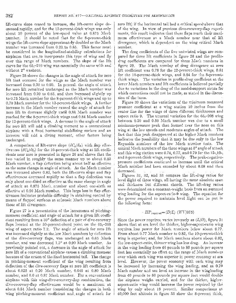
382 REPORT IfO: 877—NATIOh’AL ADV.ISORY C031M:ITTEE FOR .4EROhrAUTICS
lift-curve slope ceased to increase, the lift-curve slope de-c.reasecl rapidly, and for the 12-percent-thicl~ wings was onlyabout 30 percent of the low-speed value at 0.875 Machnumber. It should be noted that for the S-percent-thickwings the lift-curve slope approximately cloubled as the Machnumber was increased from 0.20__t_o0.85. This factor mustbe considered in the longituclinal-st~biliLy calculations forairplanes that tire. to incorporate this type of wing and flyover this range of Mach numbers. The slope of the liftcurve for the 651–21Owing was essentially the same with anclwithout 20 washout.
Figure 25 shows the changes in the angle of atta,ck for zeroIift that oc-cumed for tl~c wings as the Mach number wasincreased from 0.20 to 0.90. In general, the angle of at tarkfor zero lift remained unchanged as the Mach number wasincreased from 0.20 to 0.65, ancl then increased slightly upto 0.75 Mach number for the 8-percent-thick wings and up to0.70 Mach number for the 12-percent-t~tick wings. A furtherincrease. in th~ Ylach number caused t,be angle of attzck forzero lift to decrease slightly until 0.88 Marh number wasreached for the 8-percent-thick wings and 0.84 Mach numberfor 12-permnt-thick wings. A deerease_in the angle of attackfor zero lift will add z climbing moment. to a conventionalairplane with a fixed horizontal stabilizing surface and anincreme will add a cliving moment, other factors beingunchangecl.
A comparison of lift-curve slope (cZ~Jda) with flap effec-tiveness (dCJCi8f) for the 10-percent-thicl{ wing at lift coeffi-cients near zero is presented in figure 26 ancl shows that thetwo varied in roughly the same manner up to Qbout 0.S2T’Iach number, a. fkp deflection being abou~ half w effectiveas the same cl~ange in angIe of attack. As the Mach numberwas increased above 0.82, both the lift-curve sIope and flapcffwtivcmess decreased rapidly so that a flap deflection wasonly qbout one-third as effwtive as the. same change in angIeof attack at 0.875 hlach number and about one-sixth aseffective at, 0.90 Mach number. This large loss in flap effec-tiveness indicates probabIe difficulty i~~..obtaining control bymeans of flapped surfaces at, subsonic Mach numbers abovethose of lift divergence.
Figure 27 is a presentation of the increments of pitching-momenL eoefbicient ancl angle of attack for a given lift coeffi-cient resulting from a 30° deflection of %pair of dive-recoveryflaps Iocated at the 30-percent-chord point on the 651–208wing of aspect ratio 7.2, The angIe of attack for zero liftwas increased slightly at the.kxv Mach numbers by cIeffectionof the dive-recovery flaps, was unchanged at 0.65 llachnumber, and was decreased 1,5° aL 0.90 Mach number. Aspreviously pointed ont, mdecrease in the angle of attack forzero lift of a conventional airplane. cmuses a climbing momentbcwuse of the action of the fixed horizontal tail, The changein pitching-moment coefficient of the wing resulting fromdeflection of the dive-recovery flaps at zero lift coefficient isabout 0.025 at 0.20 Mach number, 0,040 at 0.80 Machnumber, and O.0 at 0.87 klach number. For a conventionalairplane with this wing-dive-recovery-flap corn bination, thedive-recovery-flap etl’ective~ess would be a maximum ata’boui 0,84 Mach number (considering the changes in bothwing pitching-moment coefficient ancl angle of attack for
zero lift) if the horizontal tail had a criticaI spec{+ above thatof the wing, In view of previous dive-recovery-flap exprri-mentsj this result indicates that these flaps rm.ch th(~irmtixi-mum effectiveness at a Mach number near thai of lifLdivergence, which is dependent on the wing rrit icaI J1achnumber.
Tho drag coefficients of the five untwishxi wings arc com-pared for three lift coefficients in figure 28 and tlw profilc-drag coefficients are compared for three Mach numbers infigure 29, The Mach numbey of drag di~ergence at zerolift coefficient was 0.78 for the 12-percent-thi& wings, 0.81for the 10-percent-thick wings, and 0.84 for the 8-pwccwL-thick wings. The variation in profile-drag _eoeffkienL aL thelower Mach numbers and lift coefficients is believecl part iallydue to variations in the drag of the rnoclel-support struts forwhich corrections could not. be mtidc, as stated in the discus-sion of the tarcs.
Figure 30 shows the variations of the minimum measurcclpressure coefficient at a wing station 10 inchm from thecenter line for the wings of three clifl’ercnL thicknesses nmlaspect ratio 9. The unusual v~riation for the 65,-208 }vitlgbetween ‘0.20 m-d 0.50 Mach number WIS due LO a smallminimum-pressure peak that formecl near the nose on thiswing at the low speeds and moderate angles of at tuck. ‘rhcfact that this peak disappeared at the higher J1fich numhcrsindicates lhe possibility that it may be due only to the lowReynolds numbers of the low Jfach numb~’r tesLs. ‘1’h~criticaI Jlach numbers of the three wings at 00 nnglc of aLt@and this wing station were 0.74, 0.77, and 0.7!3 for the 12-,10-,and 8-percent- thiclc \vings, respcc’ tively. The pcak-negative-pressure coefficients continued to increase untiI the criticalJfach mmher had been exceedecl by about 0.08 nnd tl](’ndecreased.
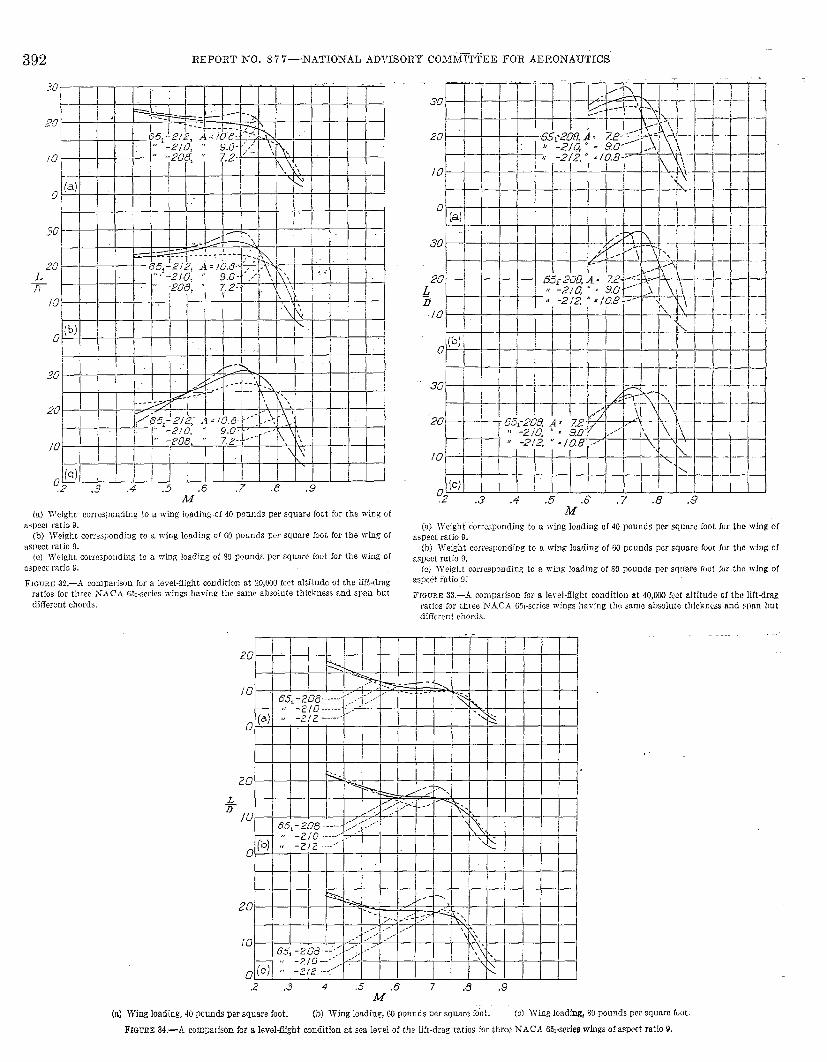
Figures 31, 32, and 33 compare. the lift-drag ratios forIeveI fight of three wings, aII having the swnc absolu Lc sp~~nancl thickness but difFerenL chords. The lift-drag rtitioswere determined on a constant-weight basis from an assumedwing loacling for the aspect-ratio-9 wing. Tlw ccluti~ion forthe power required to maintain ]evel flight can be pl]t inthe foJ_Iowing form:
HP,,,.M= (D/L) (11’17/375)
Since the power rcquirecl varies inversely as WD), figure 31shows that at sea level the thicker, higher-a.spect-ra tio wingrequires. Iess power for Jlavh nlumbers bc.low abou L 0.77.From abouL 0.77 Mach number to 0.82, the 10-per cmL-Lhirkwing is superior; and, for Jlach numbers zbove abouL 0.821the Iow-aspect-ratio, thinner wing htis ]e.ssdrag. An kcwaw
in the wing loading from 40 pounds to 80 poun(]s pvr squarofoot has.essentially no effect. on the range of Mach numlwraover which each wing w-as superior in power CCOUOIUIaL sealevel. fiowever, the power economy with each wing may
be increased by increasing the wing Ioad ing, and at. 0,70h~ach number and sea leveI an increase in the wingload ingfrom 40 pounck to 80 pounds pm square foot Jvould (loublmthe airpIane w-eight, carrieclj and for the thiclier$ higllt’r-tispe.ct-ratio wing would increase the power recluhwd bcY thiwing by only about 18 perce~it. Similar comparisons at40,000 feet altitude in figure 33 show the 8-pwccn t Lhick,

THE HIGH-SPEED CHARACTERISTICS OF SIX MODEL WINGS HAVIXG hTACA 65+iERIES SE CTIOFW 383
~.z-~speet-ratioKing to ba~e Iess drag than the other t~~o
at Mach numbers above about 0.78 for ming Ioading of 40to 60 pounck per square foot., and above 0.76 for an SO-pound-per-square-foot wing loading. An increase in the ring IoacI-ing at 40,000 feet altitude did not reduce the clrag per poundcarried as much as at sea Ievel. An airpIane, flying at 0.75Mach number with the ~0-percent-thick aspect-ratio-9wing, COUIC1increase its load 50 percent at an increase of 41percent in the power required b~ the wing by changing froma 40- to a 60-pound-per-square-foot n-~~ Ioading. .&nincrease in the wing load~m to SO pouncls per square footwouId require an increase of 114 percent in the pow-er requiredby the wing o~er that with a 40-pouncI wing loading. There-fore. the power per pound carried would be higher with theSO-pound wing Ioading than ri-ith the 40-pound -wing loacling.
Figures 34, 35, ancl 36 present comparisons of ]ift-dragratios for three wings ha-ring the same pIan form but cMfer-ent thicknesses. At sea lerei, the 8-percent-thick ringrequirecl less power for flight >lach numbers above about().75 for wing loadings from 40 to SOpounds; and the 12-per-cent-thick wing was superior below this Mach Dumber. Asin previous comparisons at sea level, increasing the wingIoading from 40 to 80 pouncls per square foot reduced thepower required by the w~m per pound carried. The com-parisons for flight at 40,000 feet (fig. 36) show the 12-percent-thick wing to be the more economical of power for Machnumbers beIo-w 0.75, and the 8-percent-tbicli wing to haveless drag for Mach numbers above 0.75.
These comparisons show that the choice of a wing section,plan form, and loading for a high-speed airpIane shoulcl bedictated by the speed and altitude at -which the proposedairpIane is to fly in order to obtain the most ef6cient -ringcharacteristics.
Figures 37 and 38 are comparisons of the wing pitching-moment coefficients at Iift. coefficients for Ievel tlight of thethree Kings ha-ring the same absolute span and thicknessbut clitTwent chords. AH three wings hzcl about the samepitching-moment coefficients for level flight at a gi~en Ioad-ingl altitude, and Mach number for Jlach numbers belowabout 0.84. The pitching-moment coefficients of the wing-for leveI flight, in general, clemeased slightly as the Machnumber was increased. The Ie-rel-flight pitching-momentcoefficients for the 12--percent-thick, 10.S-aspect-ratio Kingbegan increasing -with lkch number as the llach number~xceeded 0.82. This increase in the pitching-moment coeffi-cients of the wing at high l~ach numbers is particularitydesirable from the standpoint of reco-rery from high Machnumber dives. Figures 39 and 40 show similar comparisonsof the pitching-moment coefficients for the three wing~~-i-ary-ing only in thicliness ancl show- a close resemblance to thecomparisons of figures 37 and 38, indicating that the majorchanges in pitching-moment coefficient at the high Machnumbers are due mainly to the w@ section.
Figures 41 and 42! present the angIes of attack of thevarious wings necessary to maintain the lift coefficientsrequired for level flight. The angles of attack gene~aUydecreased as the llach number was increased, as w-ould beexpected if no chsnge in the ar@e of attack for zero Jift or in
the lift-curve slope mere encountered. At the highest Mach
numbers, and especially at higher altitudes, the 8-percent-thick wings show no tendency to require an increase in {heangle of a.ttacli for Ievel flight with Mach number as do thethicker wings. This eontinue~ decrease in the ~ecessm-yangle of attack is particularly desirable from the standpointof control in high Mach numbers dives n-here an increase inthe necessary wing angIe of attack w-iU came an increase ofthe taiI angle of attack, for a conventional airpIane, and-”thereby a div@u moment. for the airplane. This di~h–~”--moment. may become so sewre that a pilot eouId not exertthe control necessary to maintain a Ievel-flight attitude.
CONCLUSIONS
The lift-curve slopes of the moclel wings increased withS1ach number less rapidly than predicted by Glauert’s factor
for two-dimensional-flow (ljl~) for Mach numbers be-tween 0.20 and 0.50 and more rapidIy for Mach numbersabove 0.50 but beIow that of Iiff di-mrgence. Thg l&-cuwesIopes ceased to increase with Mach number above about0.78 for the 12-percent-thick wings, 0.81 for the 10-percent-tkicli wings} and 0.85 for the S-percent-thkk wirgs. Thelift-cum-e slopes of the t3-percent-thick wings were roughlytwice their low--speed values at. O.&5Mach number.
The effectiveness of a 20-percent-chord flap on Lhe 65,-210wing of aspect ratio 9 decreased rapidly as the SIach numberw-as increased beyond that of Jift. divergence for the wing.DifEculty -dI probabIy be e~countered in maintaining con-troI of an airplane soleIy by means of traihng-edge flaps &tsubsonic Mach numbers abo~e 0.871 fispecially if the surfacesha-re a thickness of 10 percent or greater.
Di_re recovery flaps on the S-percent-thick wing of aspectratio 7.2 reached their maximum effectiveness at about 0.84”Mach number. In view of pretious clive-recovery-ffap tests,tfis result indicates that. the Mach number at. which thisflap effecti~eness is a maximum is reIatecl to the critical Machnumber of the wing to which the flaps are attached.
Of tb.e sk wings tested, the one hatig 12--percent-thicksections and an aspect ratio of 10.8 w-odd give the mostefficient operation for airpIanes that are to fly near sea leveland at l~ach numbers below 0.77. The 8-percent-thick winghad Iess drag than the thicker wings of the same plan formfor Mach numbers above about 0.76.
-AMES .IEROX.+UTICAL L.~BOR*TORY,
XATIOAT.AL ADYIsoRY C’031311TTEE FoR .bmoh~z~wmcs,
MOFFETT FIELD, Cam. October 192 19&.
REFERENCES
1. N-ken, James M., Gadeberg, Burnett L.r and Hamilton, lYiIliam :.T
Correlation of the Drag Characteristics of a P-5 lB AirpIaneObtained From High-Speed Wind-Tunnel and FLight Tests,h-.&~A ACR h’O. 41032> 1925.
2. SiI~emtein, Abe, and White, James A.: Wind-Tunnel Interference ‘“ ‘-JWh Particuhm Reference to Off-Center Positions of the Wingand to the Downwa~h at the Tail. NTACARep. k-o. 547, 1935.
3. Jacobs, Eastman NT.,a~d Sherman, Albert: Airfoil Section C~arac-teristies as AiTected by Variations of the Reynolds h’umber.XACX Rep. XO. 586, 1937.
384 REPORT NO. 877—NATIONAL ADVISORY COMI&~TTEE FOR AERONAUTICS
c.
-.
-.
-.
FIGURE
Ci fot-lw=.2Zero+OO,:O,;~~OO- ~u~-For M+,2 .775 .8&Z7 ,875
,4 .65 .725 .8 ..850 ,9 ---5.—Variation of lift coefficient with mgle of attack for the NACA 65+88 wing of
fispect ration 7.2.
c.
cze::~*~roM=02~ ~-~ o f? o o;-~ 0 :
Fo.-lvf=+ w ,6 ,7 .775 .825 .875.4 .65 .725 ,8 .85 .9
FLWRE 7.—Variation of pitching-moment coefficient with fift coefficient for the I-TLC ~
WI-20S wing o f aspect ratio 7.2.
FIGURE 6.—\7ariation of drag eeefficicnt with lift coefficient for tho 2JA (!.4 t3.WN? wing of
aspect mfio 7.2,
,.
FIGURE 8,—\rariation of lift coefficient with mgle of attack fur the NAGA 651-W8 wing of
aspect ratio L

THE HIGH-SPEED CE4RACTERIST1CS OF SIX MODEL WINGS E4VING NACA 65+X3RIES SECTIONS 385
/.0
.8
.6
.4
.~L
.2
0
-.2
-.4
760472 .04 .06 .08 .[0 ./2 .1’4 ./6
CD
FIG~E ~.—~’ariation of drag meiticient with fift coefficient for the XAC A 651-ZR ~ims of&sQectI~tiO!).
1-o
.8
.6
.4
c. .2
0
-.2
-4
-.6, ~+. -./Cm@, lfbr M’. 2
g;”~z,: o .; 0 .; u $5 u .: u g a u.9.4 .65 .725 .775 .825 .87.5
FIGTXE 10.—Variation of pitchfng-mmment mefdcknt with lift coefficient for the [email protected] of aspect ratio 9.
For JW+2 .6 .7 .75 ..8 .85 .S’.4 .65 .725 .775 .825 .875
llGmz-ll.-Variation of lift cae~cient with angIe of attack forthe NACA 651-210 wktg of
espect ratio 9. &, OO.

REPORT NO. 87 7—NATIONAL AD171SORY COMLIITTEE FOR AERONAUTICS
/.0
.8
.6
.4
c. .2
0
;2
-.4
.G! .“u .02 .04 .06 .09 .10 .“f2 .[4 “-
c.
FIGUKE 12,—Variation of drag coefficient with lift coefficient for the iV.4CA 65,-210 ‘wing of
aspect ratio 9. J/, OO.
/.0
.8
.6
,d
CL ,’2
0
-.2
-.4
-.$71, “ -,.,
E=.,4fo; M-.2Zero +OOL?O;; Q,;50 .;0000for M* .2 .6
.4 .65-:85 .9 ““
.725 .775 .825 .875
FIGURE 13.—Vr,riation of pitching moment coefficient with lift coefficient [or the N~.4C A
6.51-210 wing of aspect mtio 9. $f, OO.
\
,
a for M=,.2zero+~Q:Or~u.;5D Doouofor M+ .2
.4.9
.65 .725 .775”8.8258?875FIGURE 14.—Varia[ion of lift coefficient with ang]e of attack for the XACA 05,-210 wing ‘wItl]
2° twist 5nd an aspect ratio 0f9.

THE HIGH-SPEED CHARACTERISTICS OF SIX MODEL wINGS EATING XAQ+A 65r–SERIES SECTIONS 3.87
f.2
/0
.8
.6
.4
c.
.2
0
.2
.4
.60.02 .0-+ m .08 ./0 ./2 .1-4 .78
c.
FIGURE 15.—Variation of drag ruefficient with lift coefficient for the X.4C.4 6.5~-2f0 wing
with 2° twfst and an aspect ratio of 9.
.
.6
.4
c. .2
0
.2
-4
76+f :/
C:.(. for M-.2ZerO+OO~ff-+U-;50: 0000For M&.2 .85 .9
.4 .65 .7= .775 .825 .87’5
FIGL-RE16.—Variation of pitch fng-momm.t coeficknt with lift coefHcient for the SACA*=,-210 wing with 2° twist and an aspect ration of 9.
m
,
.s
.6
.4
c. .2
0
-2
:.4
J I t Ill 1111 1 t 1.-4”-2” 0° i?” .4” 6“ 8° /5” /2” [4” /E” IX”.-
d for M=.2Zero–~U i7L7i7U0UU UUQQC?For AI+.2 .6 .7 .75 .a .85 -.9
.4 .65 .7..5 .775 .8.25 .875-..
-.

388 REPORT hTO. 877—NATIONAL ADVISORY COMMITTEE FOR AERONAUTICS
1.2
/,o
.8
.6
.4
CL
.2
0
.2
74
-.60.02 .0$ ,06 .08 .[0 .[2-:.M .ID
c.
FIQURE 18.—Variation of drag coefficient with lift coefficient for the h~ACA 651-212 wing
of aspect ratio 9.
c ~c,, for M=.4
;~M’~oOouOoOOO DOC7for M-.2
.65 .725 .775 .825 .875 .Zem+QO.~ 0,~”0,~50.~ ‘,8~0 0.6 .7 .75 .8 :85 .9 Fof-M+.2 9
.4 .65 .725 .775 .825 .&375
FIGLmE 19.—V-ariation of pitching-moment coefficient with lift coefficient for the XAC.A
651-212 wing of aspect mtio 9.
FIGURE 20.-V”ariation of lift coe5eient with angle of attack for the NA CA 6.51-212w’lngdaspect ratio 10.8.

Z’IEUilEUGH-SPEED ~RACWERISTICS OF SIX MODEL WINGS HAYLYG NACA 6 31–SERIES SECTIONS 389
m
.8
c.
Fmc:& f;r M-2Zero*U 0.:0. -;0.;50 :0:50 QFor M* .2 .g
.4 .65 .725 .775 .825 .875
FIGrRK 21.—l-ark+tion of drg mefieient with lift caeflkient for the >’.~ C-4 &-L-212 wing ofFIG mE Z.2.-%-ariafim of pitching-mommi coefficient with lift cwfTickmt for the h’.% C.~
~rL_212 ~~g ~f u.pect ratio 10.Z.&;pec;t rauo 10.S.
.—-—
. ..—
.- —
~IGtIEE 23.-Li[t4urm slopes for fire * having NACA fi-serk airfoil ssctiom.

390 REPORT hTO. 877—NATIOh’AL ADVISORY COMMITTEE FOR AEROhTAUTICS
.32
.28
.24
.20
a; ./8
./2
.08
.04
‘2 ,3 4 .5 6 7 8 9M
FIGURE 24.—The variation, with Mach number, of the estimated section lift-curreslopes
for five wings haviug .NACA 65j-series airfoil sections.
./6
. i4
%.[2
./0
.08
.06
s @d&~
.02
‘2 .3 .4 .5 .6 .7 .8 .9M
FIt;u~B 26,-l`ariation of the Iift-cw~>e sIopeand flap effectiveness with Mach smnberfor
tbe NACA 651-210 wing of aspect ratio 9 with a 0.20 chord fir@.
.r
Q
-1”
1“
D
-1°
1“
a
~r
fkr.o
. 1“
.0
-./”
P
a
-1:2 .3 .4 .5 .6 .7 .8 .9M
F1~uEE2&.-Chmges in&ngle ofatta& forzero Iiftfrom thelow+pced vahmfortlvewings
having lNA CA 65,-series airfoil sections.
“-dlii2s’”g/.75h.chord dive “ ‘,
recovery flap with,.” ‘SL-302chord fineo 30” de flection-1
Lower view
Aa
de.
.2 “- .3 .4 .5 .& .7 .8 .9M
FIG URE 27.—Incrments of single of attack and pitching-moment cmt%cfent due to the
deflection of a dive-reeovery flap on the NACA 65]-20S wing of mpwt ratio 7.2.

TEE HIGH-SPEED CH.ARACTERISTK’S OF SIS MODEL WIYGS HAYIXG &’ACA 6firSERIES SECTIOXS 391
.66
“4.0
.02
0
.06
.04
c,
.02
0
.U6
.0=4
.02
0.2 .3. .4 .5 .6 .7 .8 .9
?Bi!f+-”’””‘‘‘.6 .8
L_-1---l I-Y
w=zl=r-FIGC_EE ‘29.-Pm&le drag caeficients for five wings lmvfng N“.LCA 65eseries .siriol s+ctkms
M
FIGLRE X.—Drag mefficients for Eve wings ha~ing h7.4C.\ O&-serk airfoil aeefions
LL
-++tttkktttk-/.6
-.8
I I
it’. Y.ti[i
.Z .3 .4 .5 .cT .7 .% .SM
(a) ~-eight eorremondiw to a T+@ loadiig of 40 ponmk Cer square fmi for the wing ofaspect ratio 9.
(b) weight eorres~nding to a wing loading of&) pounds per square foot for the wfng of
LQgect ratio 9.
(c) ~“eight ewresponding to a wing loading of M! .pcmnds per square foot for the wing of
asset ratio 9.
FIGLmE 31 .—A comparison for & level-flight condition ak sea Ierei of the lift-drag ratios for
three >;.4 CA E&.wries wfngs hrivingthe same abt%dute thickness and span but ditTwent
chords.
FLGTFLE 2Q.-\’ariation of upper-surface minirrmm-presxrre Meffki@S with ~~adr number
for tin~ stalion 10.0 on three N’ACA 6.5,-aerfes m“rrga of asseet ratio 9 with the fu.?elage.
392 REPORT NO. 87 7—NATIONAL ADVISORT-COMMITTZE FOR AERONAUTICS
L-T
/0
o
30I 1 I I
jJ+??-----
20 1 I t w- A- I
1 i -., I I ,,Y. f I I
} h“ I I I I
[(c)~‘2 ,3 .4 .5 .6 .7 .8 .9
M(a) Weight conasponding to a wing loading of 40 pounds per square foot for the wing of
a-poet ratio 9.
(b) TVekht corresponding to a wing loading of 60 Pounds per square foot for the wing of
aspect ratio 9.
(cl Weight Cormpon diug to a wing loading of 80 pounds per sqnare foot for the wing of
aspect mtio 9.
FIGURE 32.—A comparison for a level-flight condition at 20,000 feet aItitude of the lift-drag
ratios for three A’AC A 651-series wings ha~.irm the same absolute thickness and span but
different chmds.
M(a) IVeight corresponding to a wing Ioading of 40 pounds pm squrm foot fur the wing of
rspect ratio 9.
(b) M’eight corre.spcmding to a wing loading of W pounds per Squaro foot fur the wfug Of
aspect ratio 9.
[c) lyei~ht cormspondh% to a ‘wing loading of SO pounds pm sqmm foot fur the wing Q(
aspect ratio 9;
FIGURE 33.—A compmisorr for a level-flight condition at 40,0W fuot e.ltitude of the lift-drag
ratios for three N.4C.4 65i.series wings ha$im? the same absulutc thickness and win but
different chords.
20
+/0
o
[ I II I
\ “.
20
10
0.2 .3 4 .5 .6 7 .8 .9
M
(8) Wing loading, 40 pouuds per square foot. (b) Wing loading, 64 pounds per square foot. (c) Wing loading, 30 pounds per squmc fw t.
FIGURE 34.— A compa[ ison for a Ievel-flfght condition at sea level of tire lift-drag ratios for three LTACA Ml-series wings of aspect ratio 9.

THE HIGH-SPEED C!HAILKTERISTICS OF SIX MODEL ‘WINGS HAYLYG A’ACA 65r–SEIUES SECTIOXS 393
30
20
10
0
30
20L
-r
10
0
40
30
20
10
0.2 ,3 .4 .5 .6 .7 .8 .9
M
(e.) JVing loading, lo pou&. persquaref~t.W ~~~ loadinawwmis Ptrswinefwt.rcjWing loading, S0 Wtmds per square foot.
FIG cm 35.-A mmparissn for a IereI-flight eondMon at W,(W feet aItitude of the draglfft.ratios for thee NACA 651-series wings of sweet ratio 9.
$
0
3U
&
m
c1
.50
20
/0
‘2 .3 4 .5- .6 7 .3 g-.W
(a) Wing Iolfiinc, 40 pounds per square fooi.
(b) Wing lowiing, w pounds per square fret.
(c) Wing [oading, S4 pounds per square foot.
FKL-RE W,.–.% emmpariscm for a IereI-fright condition st 40,KHI feet altitude of the liftdmg
ratios for three NAC A rmi-serfes wings of aspect ratio 9.
.
(a) Weight correspmxling to s wtig Ioading of 40 PXML. per square fuot for the wirE oi aspect ratio 9.
(b] Weight corrmwmcling to a wimg loading of HI pounds per square foot for the wiGg ofa.peet ratio 9.(c) Weight eorres~nding to a wing loadhrg of S5 Nmnds per square foot for the wing of sspeetratio 9.
FIGURE 37.—A cnmparkm for a IewMight condition at sea le~el of tie pitching-moment eoe&fenk for
three N-A CA Gi-series wings bsving the same absoIute thickness and span but dh7erent chords.

REPORT h’O. 8 77—.NATIONAL ADVISORY COMTWH’EE FOR AERONAUTICS
“./4
(&) }Yeight eorresponriing to a ~ing Ioadiw of 40 pounds per square foot [or the wing ofaspect ratio 9.
(b) Weight corresponding to a wing loading of 60 pounds per squai’e [cmt for the wing of
axwet ratio 9.
(c) }Veiqht corresponding to a wing loading of w porrnds per square f.ut km ttre wing of
aspect mtio 9.
I@uR E :38.—.4 WmpariSOU fOr a Ie~eI-flight condition at 40,0W feet alt.itufie of the fJitChing-
mumen t coefficients for three N.4C.4 651-s@ries rrings having the same rib sol ufe thickness
ml smm hut different chords.
.i
o
-./
.i
ocm.{+
-./
,,
II 1 t I I I I 1 I I I I I I I I
-- . .- .
-./ — -(c) “ ,-2/2-- ““
-..
2 3 .4 .5 .6 .7 .8 9M
(a) Wing loading, 40 pounds per square foot.(h) \\ring loading, 60 pounds per square foot.
(c) t~~g loading, 80 Pounds per square foot.
FJG URE 39.—A comparison for a level-flight condition at sea level of the pitching-moment
coefficients for th~ee IJAC-4 65,-series wings of asrwct ratio 9.
,/
o
-.I
.4 .5 .6 .7 .8 .9M
(a) Wing loading, 40 pounds per square foot.
(b) IYing loading, 60 pounds w’ squaro [wt.
(c) Ttlng loading, W pounds per square (WJt.
FIGURE 40.—A eomparkon for 8 level-flight condition at 40,WI feet altitu,ie of thep[tddng.mQmmt coefficients for thrw NA C.4 651-swics wirr~s Ofx+pcct ratlu 9.

THE HIGH-SPEED CEW3ACTERISTKLS OF SIX WODEL TVLXGS HAVING NACA 6 51–SERIES SECTIONS 395
++-+-+
.d .C1 .4 .6 .7 .8 .9“ M
{a] Weight correspmdhg to a wing kmding of 40 fmumls per square foci for the wing Of
a~ect ratio 9.
[b) }1’eight corresponding to a wfng Iaadbg of MI poun&Q per square fmt for the wfng of
aspeec ratio Y.
(c] W_eight mrrespondfng to a wing loading of SO IMunds per square foot for the wing of
awwct ratio 9.
.,. , I 1 II I
%++H+Hi‘:mk,,.. r ,,,
t
H
(8) Wing loading, 40 fm!mds per scfuare foot.(b} Wing Ioading, &) pxmds p+r square foot.
(e) Wing loading, 84 pounds per square foot.
FIGrI+E 42.—Angie of wtack required for IereI Right for three h7.kC.+
sspwt ratio 9.
6.Na-ks wingsCf
FIGCFZ~ .41.-.4n@ of attack requfred for IeveI tlfght for three h’ACA .S&ssrles w_II@ l!a~fng
the same absolute thickness arid span but difleretd chords.


![The Dynamic VideoBook: A Hierarchical Summarization for ...media.cs.tsinghua.edu.cn/~ahz/papers/[2013][icip]SunL-0003963.pdf · THE DYNAMIC VIDEOBOOK: A HIERARCHICAL SUMMARIZATION](https://img.dokumen.tips/doc/110x75/5c9bfdd909d3f210138c2d90/the-dynamic-videobook-a-hierarchical-summarization-for-mediacs-ahzpapers2013icipsunl-0003963pdf.jpg)


![2. 3. : 00920-4-252135 : 2019 -- 11.22 11.23[sat] /24[sunl 2,000B …tanpoponoye.org/wp-content/uploads/2019/09/amc2019.pdf · 2019. 9. 28. · < IJ 11.22 10:00 11:00 12:00 14](https://img.dokumen.tips/doc/110x75/6085efaba659cc0e2b0846e6/2-3-00920-4-252135-2019-1122-1123sat-24sunl-2000b-2019-9-28.jpg)