Embed Size (px)
Citation preview

REPAIR REFERENCE GUIDE
“World Class Quality”
REPAIR REFERENCE GUIDE
1. Hydraulic Pumps • Troubleshooting and Replacement Parts for 71201 • Troubleshooting, Repair and Replacement Parts for 71500 • Troubleshooting and Replacement Parts for 71601 • Troubleshooting and Replacement Parts for 71700
2. Electronic Refrigerant Scale • Troubleshooting and Replacement Parts for 98210-B1 • Calibration Procedure
3. Vacuum Pumps • Troubleshooting and Replacement Parts for 90060 • Troubleshooting and Replacement Parts for 90065 and 90067
4. Electronic Leak Detectors • Troubleshooting and Replacement Parts for 55100 • Troubleshooting and Replacement Parts for 55200 • Troubleshooting and Replacement Parts for 55500 • Troubleshooting and Replacement Parts for 55750
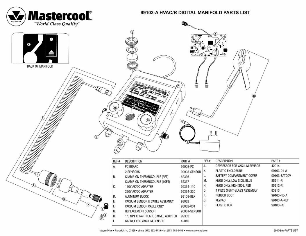
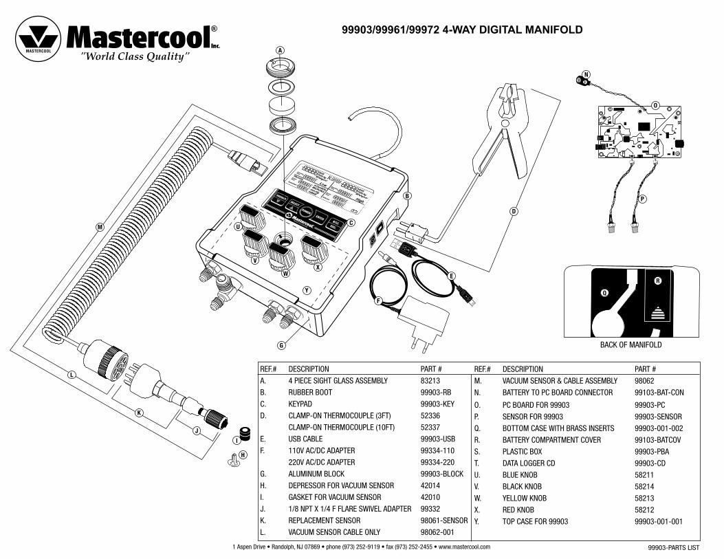
5. Digital Manifolds • Preamble: How to Re-Calibrate the 99103-A & 99903 Manifold • Vacuum Sensor Field Calibration Procedure • How to Re-Calibrate a K-Type Temperature Sensor on a Digital Manifold in the Field (99103-A & 99903) • How to Re-Calibrate a New Pressure Sensor on a Digital Manifold in the Field (99103-A & 99903) • How to Replace a Pressure Sensor on a 2-Way Digital Manifold in the Field • How to Replace a Pressure Sensor on a 4-Way Digital Manifold in the Field • Replacement Parts for 99903 • Replacement Parts for 99103-A
1 Aspen Drive • Randolph, NJ 07869 • phone (973) 252-9119 • fax (973) 252-2455 • www.mastercool.com
HYDRAULIC PUMPS
TROUBLESHOOTING(71201, 71500, 71601, 71700)
hydraulic pumps_troubleshooting
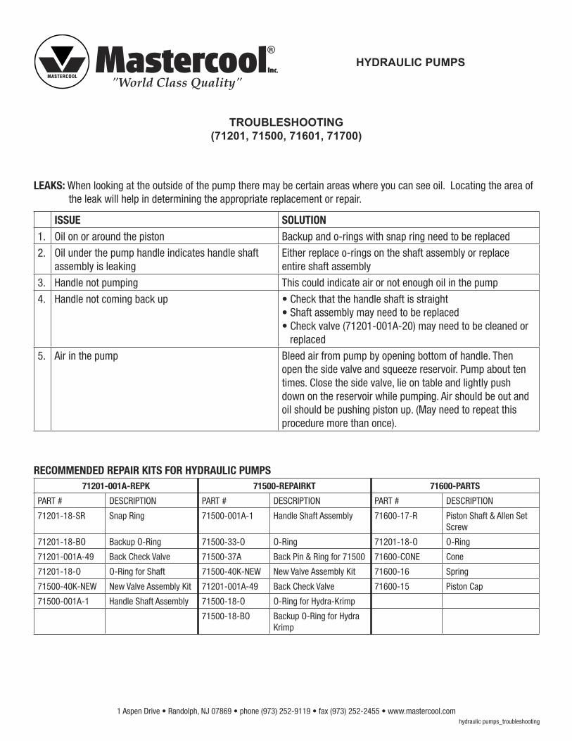
LEAKS: When looking at the outside of the pump there may be certain areas where you can see oil. Locating the area of the leak will help in determining the appropriate replacement or repair.
ISSUE SOLUTION1. Oil on or around the piston Backup and o-rings with snap ring need to be replaced
2. Oil under the pump handle indicates handle shaft assembly is leaking
Either replace o-rings on the shaft assembly or replace entire shaft assembly
3. Handle not pumping This could indicate air or not enough oil in the pump
4. Handle not coming back up • Check that the handle shaft is straight • Shaft assembly may need to be replaced • Check valve (71201-001A-20) may need to be cleaned or replaced
5. Air in the pump Bleed air from pump by opening bottom of handle. Then open the side valve and squeeze reservoir. Pump about ten times. Close the side valve, lie on table and lightly push down on the reservoir while pumping. Air should be out and oil should be pushing piston up. (May need to repeat this procedure more than once).
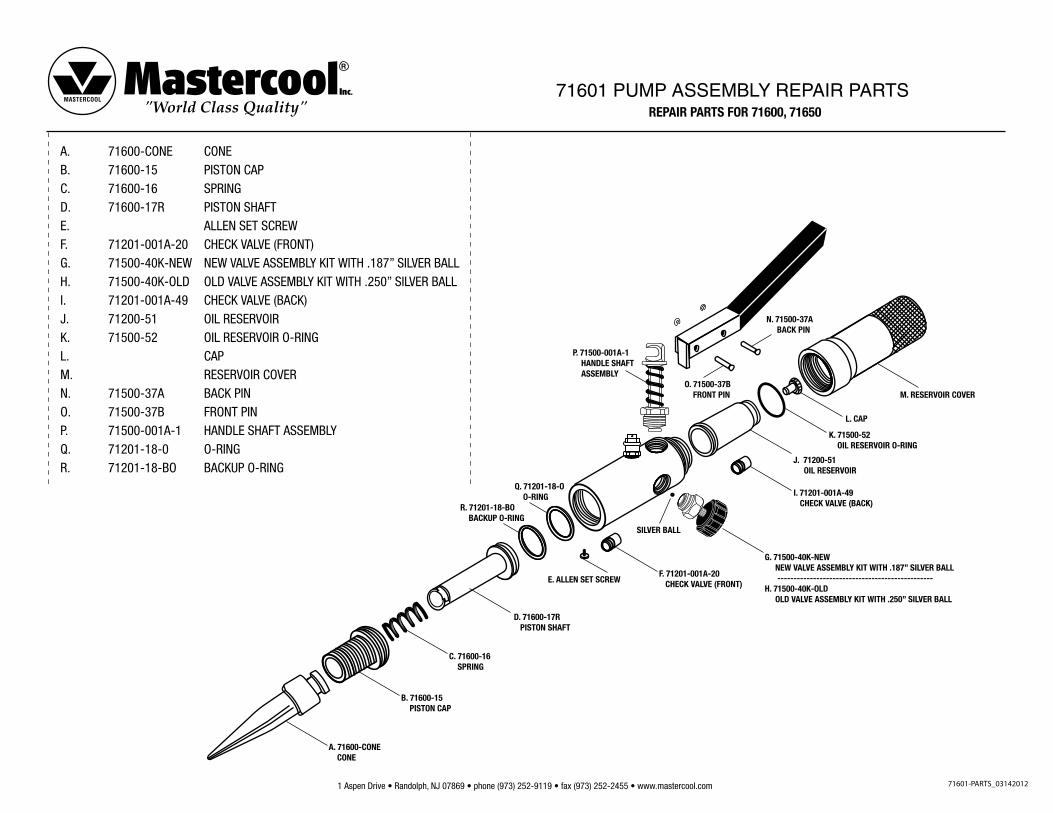
RECOMMENDED REPAIR KITS FOR HYDRAULIC PUMPS71201-001A-REPK 71500-REPAIRKT 71600-PARTS
PART # DESCRIPTION PART # DESCRIPTION PART # DESCRIPTION
71201-18-SR Snap Ring 71500-001A-1 Handle Shaft Assembly 71600-17-R Piston Shaft & Allen Set Screw
71201-18-BO Backup O-Ring 71500-33-O O-Ring 71201-18-O O-Ring
71201-001A-49 Back Check Valve 71500-37A Back Pin & Ring for 71500 71600-CONE Cone
71201-18-O O-Ring for Shaft 71500-40K-NEW New Valve Assembly Kit 71600-16 Spring
71500-40K-NEW New Valve Assembly Kit 71201-001A-49 Back Check Valve 71600-15 Piston Cap
71500-001A-1 Handle Shaft Assembly 71500-18-O O-Ring for Hydra-Krimp
71500-18-BO Backup O-Ring for Hydra Krimp
1 Aspen Drive • Randolph, NJ 07869 • phone (973) 252-9119 • fax (973) 252-2455 • www.mastercool.com
HYDRA-KRIMP
SELF REPAIRING FOR HYDRA-KRIMP ASSEMBLY (71500)
71500-REPAIR
Please reference 71500-PARTS
LEAKING ON TWO COMMON PLACES ON SECTION ‘A’
1. Around shaft assembly under handle.
2. Around piston shaft under yoke.
FOR REPLACING HAND SHAFT ASSEMBLY UNDER HANDLE
1. Remove snap-ring on the pin No. 37A.
2. Remove the handle No. 56.
3. Unscrew nut No. 35.
4. Remove the complete shaft.
5. Replace it with the new shaft assembly.
FOR REPLACING THE DOUBLE LAYER O-RING AROUND THE PISTON SHAFT UNDER YOKE
1. Remove screw No. 20.
2. Unscrew piston cap No. 15.
3. Remove piston cap, piston shaft, piston spring, No : 15, 16, 17.
4. Replace double layer o-ring No. 18.
1 Aspen Drive • Randolph, NJ 07869 • phone (973) 252-9119 • fax (973) 252-2455 • www.mastercool.com
ELECTRONIC CHARGING SCALE
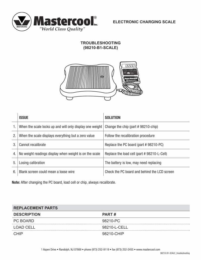
TROUBLESHOOTING(98210-B1-SCALE)
REPLACEMENT PARTSDESCRIPTION PART #PC BOARD 98210-PCLOAD CELL 98210-L-CELLCHIP 98210-CHIP
98210-B1-SCALE_troubleshooting
ISSUE SOLUTION
1. When the scale locks up and will only display one weight Change the chip (part # 98210-chip)
2. When the scale displays everything but a zero value Follow the recalibration procedure
3. Cannot recalibrate Replace the PC board (part # 98210-PC)
4. No weight readings display when weight is on the scale Replace the load cell (part # 98210-L-Cell)
5. Losing calibration The battery is low, may need replacing
6. Blank screen could mean a loose wire Check the PC board and behind the LCD screen
Note: After changing the PC board, load cell or chip, always recalibrate.
R
0000
1 Aspen Drive • Randolph, NJ 07869 • phone (973) 252-9119 • fax (973) 252-2455 • www.mastercool.com
98210 – B1 CALIBRATION PROCEDURE 1. Press ON/OFF then immediately press CLEAR + TARE/ENTER simultaneously 2. You will then see SET-1 on the LCD
3. Press TARE/ENTER again You will then see SET-11
4. Press TARE/ENTER again You will see CAL followed by a 5 digit number
5. Press ↓ (down arrow) You will see “ZERO” appear on the bottom left side of the LCD momentarily
6. Place a known calibrated weight on the platform The number on the LCD will change to a new 5 digit number 7. After the new five digits become stabilized, Press ↑ (UP arrow)
8. You will see the word “TARE” appear in the middle of the LCD for a moment
9. Press TARE/ENTER again and you will see GOOD
10. Press UNIT/SHIFT and in combination with the ↑ and ↓ (UP/DOWN arrow keys) set the proper display that corresponds to the exact weight that is placed on the platform
11. When you have completed setting the display in agreement with the actual weight press TARE/ENTER again and you will see GOOD followed by HELLO and the actual weight amount will appear on the LCD again
12. Calibration is completed. Remove the weight from the platform and the scale should read 0.000
ELECTRONIC CHARGING SCALE
98210-B1-calibration
1 Aspen Drive • Randolph, NJ 07869 • phone (973) 252-9119 • fax (973) 252-2455 • www.mastercool.com
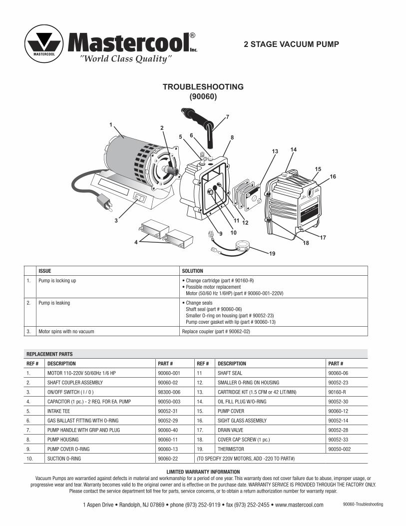
2 STAGE VACUUM PUMP
TROUBLESHOOTING(90060)
90060-Troubleshooting
REPLACEMENT PARTS
REF # DESCRIPTION PART # REF # DESCRIPTION PART #
1. MOTOR 110-220V 50/60Hz 1/6 HP 90060-001 11 SHAFT SEAL 90060-06
2. SHAFT COUPLER ASSEMBLY 90060-02 12. SMALLER O-RING ON HOUSING 90052-23
3. ON/OFF SWITCH ( I / 0 ) 98300-006 13. CARTRIDGE KIT (1.5 CFM or 42 LIT/MIN) 90160-R
4. CAPACITOR (1 pc.) - 2 REQ. FOR EA. PUMP 90050-003 14. OIL FILL PLUG W/O-RING 90052-30
5. INTAKE TEE 90052-31 15. PUMP COVER 90060-12
6. GAS BALLAST FITTING WITH O-RING 90052-29 16. SIGHT GLASS ASSEMBLY 90052-14
7. PUMP HANDLE WITH GRIP AND PLUG 90060-40 17. DRAIN VALVE 90052-28
8. PUMP HOUSING 90060-11 18. COVER CAP SCREW (1 pc.) 90052-33
9. PUMP COVER O-RING 90060-13 19. THERMISTOR 90050-002
10. SUCTION O-RING 90060-22 (TO SPECIFY 220V MOTORS, ADD -220 TO PART#)
LIMITED WARRANTY INFORMATIONVacuum Pumps are warrantied against defects in material and workmanship for a period of one year. This warranty does not cover failure due to abuse, improper usage, or
progressive wear and tear. Warranty becomes valid to the original owner and is effective on the purchase date. WARRANTY SERVICE IS PROVIDED THROUGH THE FACTORY ONLY. Please contact the service department toll free for parts, service concerns, or to obtain a return authorization number for warranty repair.
�
1 2
3
4
5 6
7
8
9 10
11 12
13 14
1516
1718
19
ISSUE SOLUTION
1. Pump is locking up • Change cartridge (part # 90160-R)• Possible motor replacement Motor (50/60 Hz 1/6HP) (part # 90060-001-220V)
2. Pump is leaking • Change seals Shaft seal (part # 90060-06) Smaller O-ring on housing (part # 90052-23) Pump cover gasket with lip (part # 90060-13)
3. Motor spins with no vacuum Replace coupler (part # 90062-02)
1 Aspen Drive • Randolph, NJ 07869 • phone (973) 252-9119 • fax (973) 252-2455 • www.mastercool.com
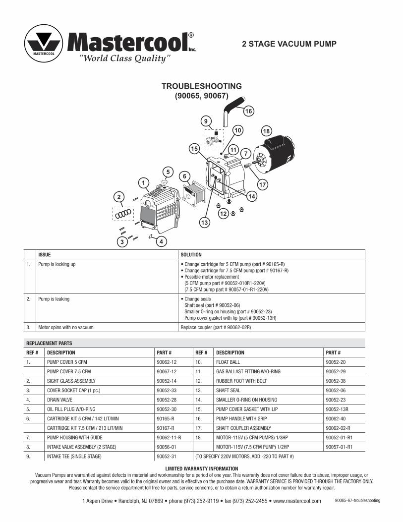
2 STAGE VACUUM PUMP
TROUBLESHOOTING(90065, 90067)
90065-67-troubleshooting
ISSUE SOLUTION
1. Pump is locking up • Change cartridge for 5 CFM pump (part # 90165-R)• Change cartridge for 7.5 CFM pump (part # 90167-R) • Possible motor replacement (5 CFM pump part # 90052-010R1-220V) (7.5 CFM pump part # 90057-01-R1-220V)
2. Pump is leaking • Change seals Shaft seal (part # 90052-06) Smaller O-ring on housing (part # 90052-23) Pump cover gasket with lip (part # 90052-13R)
3. Motor spins with no vacuum Replace coupler (part # 90062-02R)
2
3
1
56
12
11
13
15
14
7
10
17
169
18
4
REPLACEMENT PARTS
REF # DESCRIPTION PART # REF # DESCRIPTION PART #
1. PUMP COVER 5 CFM 90062-12 10. FLOAT BALL 90052-20
PUMP COVER 7.5 CFM 90067-12 11. GAS BALLAST FITTING W/O-RING 90052-29
2. SIGHT GLASS ASSEMBLY 90052-14 12. RUBBER FOOT WITH BOLT 90052-38
3. COVER SOCKET CAP (1 pc.) 90052-33 13. SHAFT SEAL 90052-06
4. DRAIN VALVE 90052-28 14. SMALLER O-RING ON HOUSING 90052-23
5. OIL FILL PLUG W/O-RING 90052-30 15. PUMP COVER GASKET WITH LIP 90052-13R
6. CARTRIDGE KIT 5 CFM / 142 LIT/MIN 90165-R 16. PUMP HANDLE WITH GRIP 90062-40
CARTRIDGE KIT 7.5 CFM / 213 LIT/MIN 90167-R 17. SHAFT COUPLER ASSEMBLY 90062-02-R
7. PUMP HOUSING WITH GUIDE 90062-11-R 18. MOTOR-115V (5 CFM PUMPS) 1/3HP 90052-01-R1
8. INTAKE VALVE ASSEMBLY (2 STAGE) 90056-01 MOTOR-115V (7.5 CFM PUMP) 1/2HP 90057-01-R1
9. INTAKE TEE (SINGLE STAGE) 90052-31 (TO SPECIFY 220V MOTORS, ADD -220 TO PART #)
LIMITED WARRANTY INFORMATIONVacuum Pumps are warrantied against defects in material and workmanship for a period of one year. This warranty does not cover failure due to abuse, improper usage, or
progressive wear and tear. Warranty becomes valid to the original owner and is effective on the purchase date. WARRANTY SERVICE IS PROVIDED THROUGH THE FACTORY ONLY. Please contact the service department toll free for parts, service concerns, or to obtain a return authorization number for warranty repair.

1 Aspen Drive • Randolph, NJ 07869 • phone (973) 252-9119 • fax (973) 252-2455 • www.mastercool.com
ELECTRONIC LEAK DETECTOR
TROUBLESHOOTING(55100)
REPLACEMENT PARTSDESCRIPTION PART #SENSOR 55100-SENPROBE 55100-PRPC BOARD 55100-PCKEY PAD 55100-KEYLED LIGHT 55100-LED
55100-troubleshooting
Battery Check: Always check the batteries before any kind of repair. Weak batteries can create false readings.
ISSUE SOLUTION1. No keypad reaction Replace the keypad (55100-KEY)
2. No leak readings • The sensor may need to be replaced (55100-SEN) (Sensors usually last around 20 hours)• The probe may need to be replaced (55100-PR)
3. When the unit is not responding to any function • Look for loose or broken wires on the PC board • May need to change the PC board (55100-PC)
4. LED lights do not show any readings Replace the LED light (55100-LED)
1 Aspen Drive • Randolph, NJ 07869 • phone (973) 252-9119 • fax (973) 252-2455 • www.mastercool.com
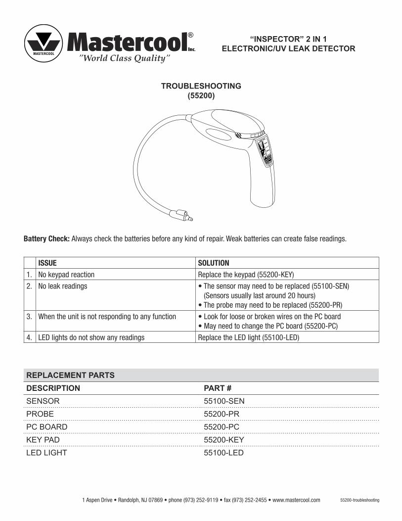
“INSPECTOR” 2 IN 1 ELECTRONIC/UV LEAK DETECTOR
TROUBLESHOOTING(55200)
55200-troubleshooting
REPLACEMENT PARTSDESCRIPTION PART #SENSOR 55100-SENPROBE 55200-PRPC BOARD 55200-PCKEY PAD 55200-KEYLED LIGHT 55100-LED
Battery Check: Always check the batteries before any kind of repair. Weak batteries can create false readings.
ISSUE SOLUTION1. No keypad reaction Replace the keypad (55200-KEY)
2. No leak readings • The sensor may need to be replaced (55100-SEN) (Sensors usually last around 20 hours)• The probe may need to be replaced (55200-PR)
3. When the unit is not responding to any function • Look for loose or broken wires on the PC board • May need to change the PC board (55200-PC)
4. LED lights do not show any readings Replace the LED light (55100-LED)

1 Aspen Drive • Randolph, NJ 07869 • phone (973) 252-9119 • fax (973) 252-2455 • www.mastercool.com
ELECTRONIC LEAK DETECTOR WITH HEATER SENSOR
TROUBLESHOOTING(55500)
55500-troubleshooting
REPLACEMENT PARTSDESCRIPTION PART #SENSOR 55500-SENPROBE 55500-PRPC BOARD 55500-PCKEY PAD 55200-KEYLED LIGHT 55100-LEDBATTERY WIRE 55500-WIRE
Battery Check: Always check the batteries before any kind of repair. Weak batteries can create false readings.
ISSUE SOLUTION1. No keypad reaction Replace the keypad (55200-KEY)
2. No leak readings • The sensor may need to be replaced (55500-SEN) (Sensors usually last around 20 hours)• The probe may need to be replaced (55500-PR)
3. When the unit is not responding to any function • Look for loose or broken wires on the PC board • May need to change the PC board (55500-PC)
4. LED lights do not show any readings Replace the LED light (55100-LED)
5. Broken wire on PC board connecting to battery Change the battery wire (55500-WIRE)
1 Aspen Drive • Randolph, NJ 07869 • phone (973) 252-9119 • fax (973) 252-2455 • www.mastercool.com
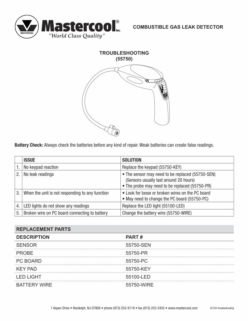
COMBUSTIBLE GAS LEAK DETECTOR
TROUBLESHOOTING(55750)
55750-troubleshooting
REPLACEMENT PARTSDESCRIPTION PART #SENSOR 55750-SENPROBE 55750-PRPC BOARD 55750-PCKEY PAD 55750-KEYLED LIGHT 55100-LEDBATTERY WIRE 55750-WIRE
Battery Check: Always check the batteries before any kind of repair. Weak batteries can create false readings.
ISSUE SOLUTION1. No keypad reaction Replace the keypad (55750-KEY)
2. No leak readings • The sensor may need to be replaced (55750-SEN) (Sensors usually last around 20 hours)• The probe may need to be replaced (55750-PR)
3. When the unit is not responding to any function • Look for loose or broken wires on the PC board • May need to change the PC board (55750-PC)
4. LED lights do not show any readings Replace the LED light (55100-LED)
5. Broken wire on PC board connecting to battery Change the battery wire (55750-WIRE)
Mastercool Inc. • 1 Aspen Drive Randolph, NJ 07869 • (973) 252-9119 • Fax (973) 252-2455 • www.mastercool.com 1
PREAMBLE
HOW TO RE-CALIBRATE THE 99103-A & 99903 MANIFOLD
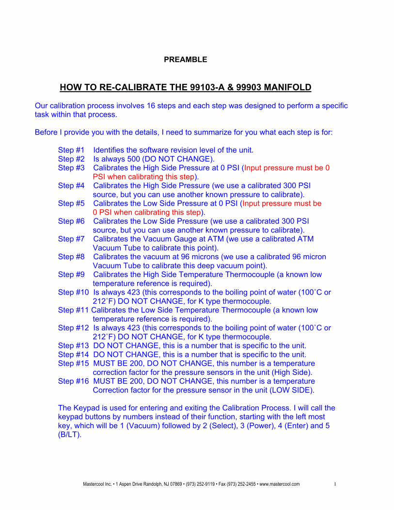
Our calibration process involves 16 steps and each step was designed to perform a specific task within that process.
Before I provide you with the details, I need to summarize for you what each step is for:
Step #1 Identifies the software revision level of the unit. Step #2 Is always 500 (DO NOT CHANGE). Step #3 Calibrates the High Side Pressure at 0 PSI (Input pressure must be 0
PSI when calibrating this step). Step #4 Calibrates the High Side Pressure (we use a calibrated 300 PSI
source, but you can use another known pressure to calibrate). Step #5 Calibrates the Low Side Pressure at 0 PSI (Input pressure must be
0 PSI when calibrating this step). Step #6 Calibrates the Low Side Pressure (we use a calibrated 300 PSI
source, but you can use another known pressure to calibrate). Step #7 Calibrates the Vacuum Gauge at ATM (we use a calibrated ATM
Vacuum Tube to calibrate this point). Step #8 Calibrates the vacuum at 96 microns (we use a calibrated 96 micron
Vacuum Tube to calibrate this deep vacuum point). Step #9 Calibrates the High Side Temperature Thermocouple (a known low
temperature reference is required). Step #10 Is always 423 (this corresponds to the boiling point of water (100˚C or
212˚F) DO NOT CHANGE, for K type thermocouple. Step #11 Calibrates the Low Side Temperature Thermocouple (a known low
temperature reference is required). Step #12 Is always 423 (this corresponds to the boiling point of water (100˚C or
212˚F) DO NOT CHANGE, for K type thermocouple. Step #13 DO NOT CHANGE, this is a number that is specific to the unit. Step #14 DO NOT CHANGE, this is a number that is specific to the unit. Step #15 MUST BE 200, DO NOT CHANGE, this number is a temperature
correction factor for the pressure sensors in the unit (High Side). Step #16 MUST BE 200, DO NOT CHANGE, this number is a temperature Correction factor for the pressure sensor in the unit (LOW SIDE). The Keypad is used for entering and exiting the Calibration Process. I will call the keypad buttons by numbers instead of their function, starting with the left most key, which will be 1 (Vacuum) followed by 2 (Select), 3 (Power), 4 (Enter) and 5 (B/LT).
Mastercool Inc. • 1 Aspen Drive Randolph, NJ 07869 • (973) 252-9119 • Fax (973) 252-2455 • www.mastercool.com 2
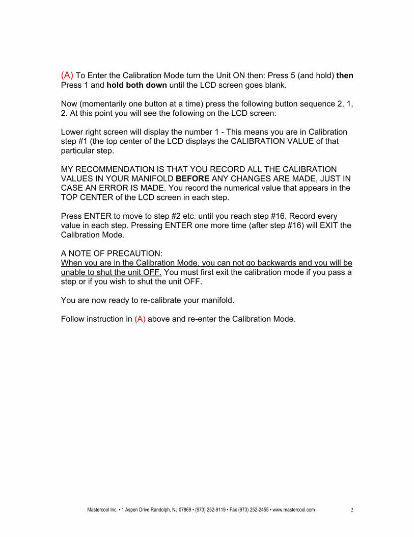
(A) To Enter the Calibration Mode turn the Unit ON then: Press 5 (and hold) then Press 1 and hold both down until the LCD screen goes blank. Now (momentarily one button at a time) press the following button sequence 2, 1, 2. At this point you will see the following on the LCD screen: Lower right screen will display the number 1 - This means you are in Calibration step #1 (the top center of the LCD displays the CALIBRATION VALUE of that particular step. MY RECOMMENDATION IS THAT YOU RECORD ALL THE CALIBRATION VALUES IN YOUR MANIFOLD BEFORE ANY CHANGES ARE MADE, JUST IN CASE AN ERROR IS MADE. You record the numerical value that appears in the TOP CENTER of the LCD screen in each step. Press ENTER to move to step #2 etc. until you reach step #16. Record every value in each step. Pressing ENTER one more time (after step #16) will EXIT the Calibration Mode. A NOTE OF PRECAUTION: When you are in the Calibration Mode, you can not go backwards and you will be unable to shut the unit OFF. You must first exit the calibration mode if you pass a step or if you wish to shut the unit OFF. You are now ready to re-calibrate your manifold. Follow instruction in (A) above and re-enter the Calibration Mode.
Mastercool Inc. • 1 Aspen Drive Randolph, NJ 07869 • (973) 252-9119 • Fax (973) 252-2455 • www.mastercool.com
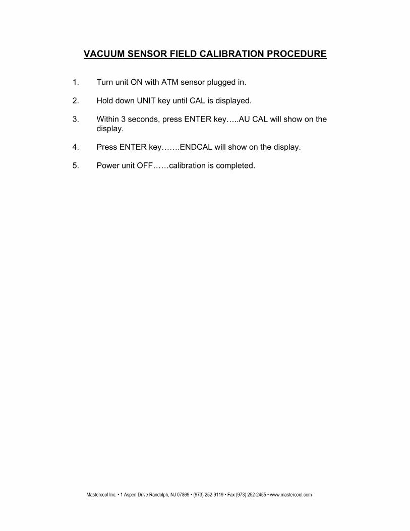
VACUUM SENSOR FIELD CALIBRATION PROCEDURE
1. Turn unit ON with ATM sensor plugged in.
2. Hold down UNIT key until CAL is displayed.
3. Within 3 seconds, press ENTER key…..AU CAL will show on the display.
4. Press ENTER key…….ENDCAL will show on the display.
5. Power unit OFF……calibration is completed.
Mastercool Inc. • 1 Aspen Drive Randolph, NJ 07869 • (973) 252-9119 • Fax (973) 252-2455 • www.mastercool.com
1
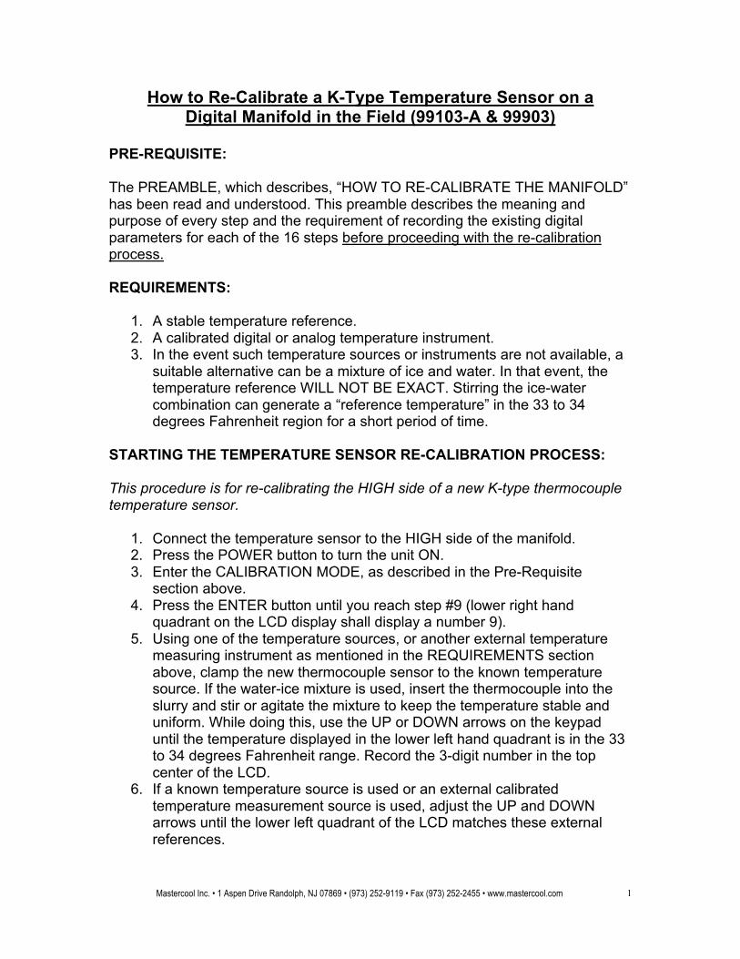
How to Re-Calibrate a K-Type Temperature Sensor on a Digital Manifold in the Field (99103-A & 99903)
PRE-REQUISITE: The PREAMBLE, which describes, “HOW TO RE-CALIBRATE THE MANIFOLD” has been read and understood. This preamble describes the meaning and purpose of every step and the requirement of recording the existing digital parameters for each of the 16 steps before proceeding with the re-calibration process. REQUIREMENTS:
1. A stable temperature reference. 2. A calibrated digital or analog temperature instrument. 3. In the event such temperature sources or instruments are not available, a
suitable alternative can be a mixture of ice and water. In that event, the temperature reference WILL NOT BE EXACT. Stirring the ice-water combination can generate a “reference temperature” in the 33 to 34 degrees Fahrenheit region for a short period of time.
STARTING THE TEMPERATURE SENSOR RE-CALIBRATION PROCESS: This procedure is for re-calibrating the HIGH side of a new K-type thermocouple temperature sensor.
1. Connect the temperature sensor to the HIGH side of the manifold. 2. Press the POWER button to turn the unit ON. 3. Enter the CALIBRATION MODE, as described in the Pre-Requisite
section above. 4. Press the ENTER button until you reach step #9 (lower right hand
quadrant on the LCD display shall display a number 9). 5. Using one of the temperature sources, or another external temperature
measuring instrument as mentioned in the REQUIREMENTS section above, clamp the new thermocouple sensor to the known temperature source. If the water-ice mixture is used, insert the thermocouple into the slurry and stir or agitate the mixture to keep the temperature stable and uniform. While doing this, use the UP or DOWN arrows on the keypad until the temperature displayed in the lower left hand quadrant is in the 33 to 34 degrees Fahrenheit range. Record the 3-digit number in the top center of the LCD.
6. If a known temperature source is used or an external calibrated temperature measurement source is used, adjust the UP and DOWN arrows until the lower left quadrant of the LCD matches these external references.
Mastercool Inc. • 1 Aspen Drive Randolph, NJ 07869 • (973) 252-9119 • Fax (973) 252-2455 • www.mastercool.com
2
7. Press ENTER one more time to get into step #10 of the calibration process. The number in the top center of the display should be 423. Do not change that number.
8. Press ENTER repeatedly until you go past step #16. 9. You have completed the re-calibration of the temperature sensor for the
HIGH side of the digital manifold. This procedure is for re-calibrating the LOW side of a new K-Type thermocouple temperature sensor.
1. Connect the temperature sensor to the LOW side of the manifold. 2. Press the POWER button and turn the unit ON. 3. Enter the CALIBRATION MODE, as described in the Pre-Requisite
section above. 4. Press the ENTER button until you reach step #11 (lower right hand
quadrant on the LCD shall display a number 11). 5. Using one of the temperature sources or another external temperature
measuring instrument as mentioned in the REQUIREMENTS section above; clamp the new thermocouple sensor to the known temperature source. If the water-ice mixture is used, insert the thermocouple into the slurry and stir or agitate the mixture to keep the temperature stable and uniform. While doing this, use the UP or DOWN arrows on the keypad until the temperature displayed in the lower left hand quadrant is in the 33 to 34 degrees Fahrenheit range. Record the 3-digit number in the top center of the LCD.
6. If a known temperature source is used or an external calibrated temperature measurement source is used, adjust the UP and DOWN arrows until the lower left quadrant of the LCD matches these external references.
7. Press ENTER one more time to get into step #12 of the calibration process. The number in the top center of the display should be 423. Do not change that number.
8. Press ENTER repeatedly until you go past step #16. 9. You have completed the re-calibration of the temperature sensor for the
LOW side of the digital manifold.
Mastercool Inc. • 1 Aspen Drive Randolph, NJ 07869 • (973) 252-9119 • Fax (973) 252-2455 • www.mastercool.com
1
HOW TO RE-CALIBRATE A NEW PRESSURE SENSOR ON A DIGITAL MANIFOLD IN THE FIELD (99103-A & 99903)
GENERAL: Whenever a manifold experiences a pressure sensor replacement, the manifold requires re-calibration. Two (2) known pressures will be required to re-establish the accuracy of the manifold. Determining which steps in the calibration are required to be modified will depend on whether the low side or high side sensor was replaced. If the pressure sensor on the low side was replaced: step #5 and step #6 need to be changed. If the pressure sensor on the high side was replaced: step #3 and step #4 need to be changed. The calibration parameters in all other steps must remain un-changed. PRE-REQUISITE: It is presumed that the following events have taken place.
• The directions describing “How to Replace a Pressure Sensor in the Digital Manifold” have been read and the defective pressure sensor has been replaced.
• The Preamble, which describes, “How to Re-Calibrate the Manifold”
has been read and understood. This preamble describes the meaning and the purpose of every step.
• The pre-requisite of recording the existing parameters for all 16 steps has been met before proceeding with the re-calibration process.
REQUIREMENTS:
• Any stable source of air pressure in the 0 PSI to 300 PSI range.
• One side (low side) or the other side (high side) is still calibrated and will be used as a reference to re-calibrate the side with the new pressure sensor.
• Zero PSI will be one of the pressures used for calibration. The second pressure should be in the 200 to 250 PSI range. The exact value of the high pressure is not important.
Mastercool Inc. • 1 Aspen Drive Randolph, NJ 07869 • (973) 252-9119 • Fax (973) 252-2455 • www.mastercool.com
2
STARTING THE RE-CALIBRATION PROCESS – HIGH SIDE: This procedure is for re-calibrating the HIGH SIDE with the new pressure sensor
1. Press the POWER button to turn the unit ON.
2. To enter the calibration process: Press the B/LT button (and hold) then press VACUUM (hold both until the LCD screen goes blank). Next, press the following sequence (momentarily one button at a time), SELECT-VACUUM-SELECT. When the number 1 appears in the lower right quadrant, you are in Step #1 of the calibration process.
3. Calibrating the zero PSI point for the high side is done in Step #3. Press
ENTER two more times until the lower right hand quadrant display shows the number 3. At this point use the UP arrow (select button) or the DOWN arrow (vacuum button) until the upper right hand quadrant displays 0 PSI.
4. Record the calibration parameter that appears in the top center of the
LCD. This information should be entered with the calibration data for Step #3 that was initially recorded for future use.
5. A second pressure calibration point is required for the high side to
complete the re-calibration. • Turn the high side, low side and vacuum knobs fully counter-
clockwise (open position). • Install the black plastic caps on the low side and high side ports
and tighten them by hand, making certain that they are tight. The refrigerant (yellow) knob should be in the horizontal (fully clockwise) position.
• Wear safety glasses and connect a pressure source of 150 PSI (minimum) but not greater than 300 PSI to the vacuum port.
• Turn the compressor on until a maximum PSI is attained. Turn the vacuum knob fully clockwise to the closed position. This keeps the pressure constant inside the manifold.
6. Now press the ENTER button to advance the calibration to Step #4. You
should see a 4 in the lower ride quadrant of the LCD.
7. You will observe a PSI reading on the high side. You need to exit the calibration mode to see what the PSI reading is on the low side of the LCD display. The presumption is that the low side is calibrated.
8. Press ENTER 13 more times until the manifold exits the CAL. MODE. You will now record (on a piece of paper) the PSI reading on the low side. This is an accurate PSI pressure valve that you will also want the LCD to display on the high side. You will accomplish this by following the instructions in the next step.
Mastercool Inc. • 1 Aspen Drive Randolph, NJ 07869 • (973) 252-9119 • Fax (973) 252-2455 • www.mastercool.com
3
9. Follow the instructions in Step #1 above and re-enter the calibration mode.
Press ENTER 3 times. You should now be in Step #4. Now use the UP arrow (select button) or DOWN arrow (vacuum button) until the pressure reading on the high side matches the number that you recorded on the piece of paper in Step #8 above.
10. To exit, continue pressing ENTER until you pass Step #16. Check that the
high and low PSI readings on the LCD display are the same or within +/- 0.5% error. When this is accomplished, the re-calibration process is completed.
STARTING THE RE-CALIBRATION PROCESS – LOW SIDE: This procedure is for re-calibrating the LOW SIDE with the new pressure sensor.
11. Press the POWER button to turn the unit ON.
12. To enter the calibration process: Press the B/LT button (and hold) then press VACUUM (hold both until the LCD screen goes blank). Next, press the following sequence (momentarily one button at a time), SELECT-VACUUM-SELECT. When the number 1 appears in the lower right quadrant, you are in Step #1 of the calibration process.
13. Calibrating the zero PSI point for the low side is done in Step #5. Press
ENTER four more times until the lower right hand quadrant display shows the number 5. At this point use the UP arrow (select button) or the DOWN arrow (vacuum button) until the upper left hand quadrant displays 0 PSI.
14. Record the calibration parameter that appears in the top center of the
LCD. This information should be entered with the calibration data for Step #5 that was initially recorded for future use.
15. A second pressure calibration point is required for the low side to
complete the re-calibration. • Turn the high side, low side and vacuum knobs fully counter-
clockwise (open position). • Install the black plastic caps on the low side and high side ports
and tighten them by hand, making certain that they are tight. The refrigerant (yellow) knob should be in the horizontal (fully clockwise) position.
• Wear safety glasses and connect a pressure source of 150 PSI (minimum) but not greater than 300 PSI to the vacuum port.
• Turn the compressor on until a maximum PSI is attained. • Turn the vacuum knob fully clockwise to the closed position. This
keeps the pressure constant inside the manifold.
Mastercool Inc. • 1 Aspen Drive Randolph, NJ 07869 • (973) 252-9119 • Fax (973) 252-2455 • www.mastercool.com
4
16. Now press the ENTER button to advance the calibration to Step #6. You should see a 6 in the lower ride quadrant of the LCD. You will observe some PSI reading on the LOW SIDE. You need to exit the calibration mode to see what the PSI reading is on the HIGH SIDE of the LCD display. The presumption is that the high side is calibrated.
17. Press ENTER 13 more times until the manifold exits the CAL. MODE. You
will now record (on a piece of paper) the PSI reading on the high side. This is the PSI number that you want the LCD to display on the low side. You will accomplish this by following the instructions in the next step.
18. Follow the instructions in Step #1 above and re-enter the calibration
mode. Press ENTER 5 times. You should now be in Step #6. Now use the UP arrow (select button) or DOWN arrow (vacuum button) until the pressure reading on the low side matches the PSI reading that you recorded on the piece of paper in Step #17 above.
19. To exit, continue pressing ENTER until you pass Step #16. Check that the
low and high side PSI readings on the LCD display are the same or within +/- 0.5% error. When this is accomplished, the re-calibration process is completed.
Mastercool Inc. • 1 Aspen Drive Randolph, NJ 07869 • (973) 252-9119 • Fax (973) 252-2455 • www.mastercool.com
1
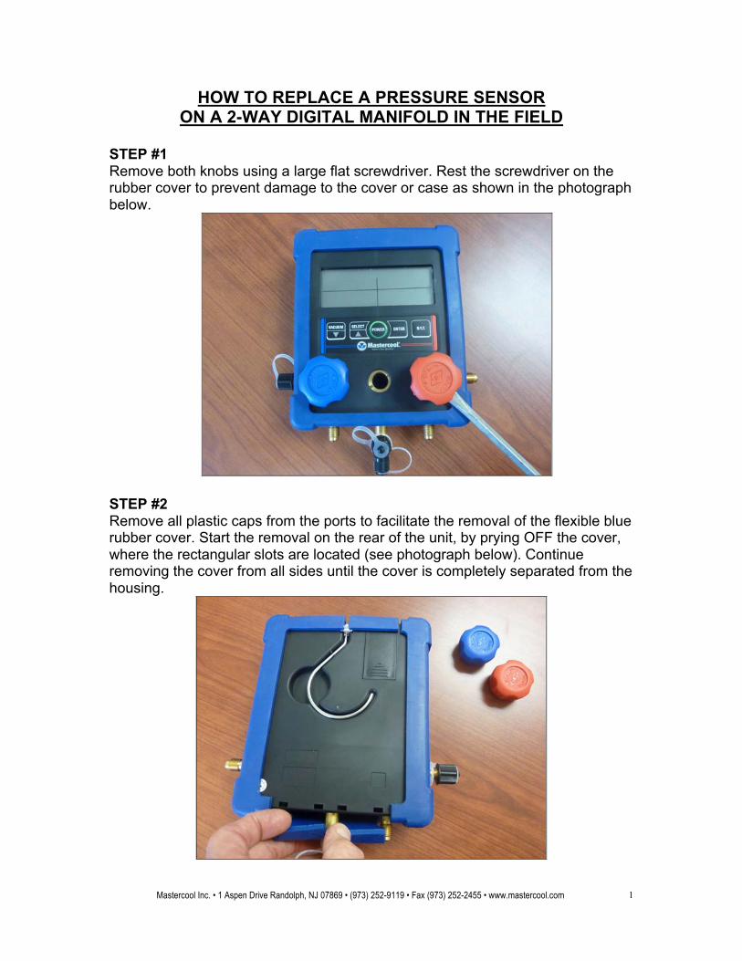
HOW TO REPLACE A PRESSURE SENSOR ON A 2-WAY DIGITAL MANIFOLD IN THE FIELD
STEP #1 Remove both knobs using a large flat screwdriver. Rest the screwdriver on the rubber cover to prevent damage to the cover or case as shown in the photograph below.
STEP #2 Remove all plastic caps from the ports to facilitate the removal of the flexible blue rubber cover. Start the removal on the rear of the unit, by prying OFF the cover, where the rectangular slots are located (see photograph below). Continue removing the cover from all sides until the cover is completely separated from the housing.
Mastercool Inc. • 1 Aspen Drive Randolph, NJ 07869 • (973) 252-9119 • Fax (973) 252-2455 • www.mastercool.com
2
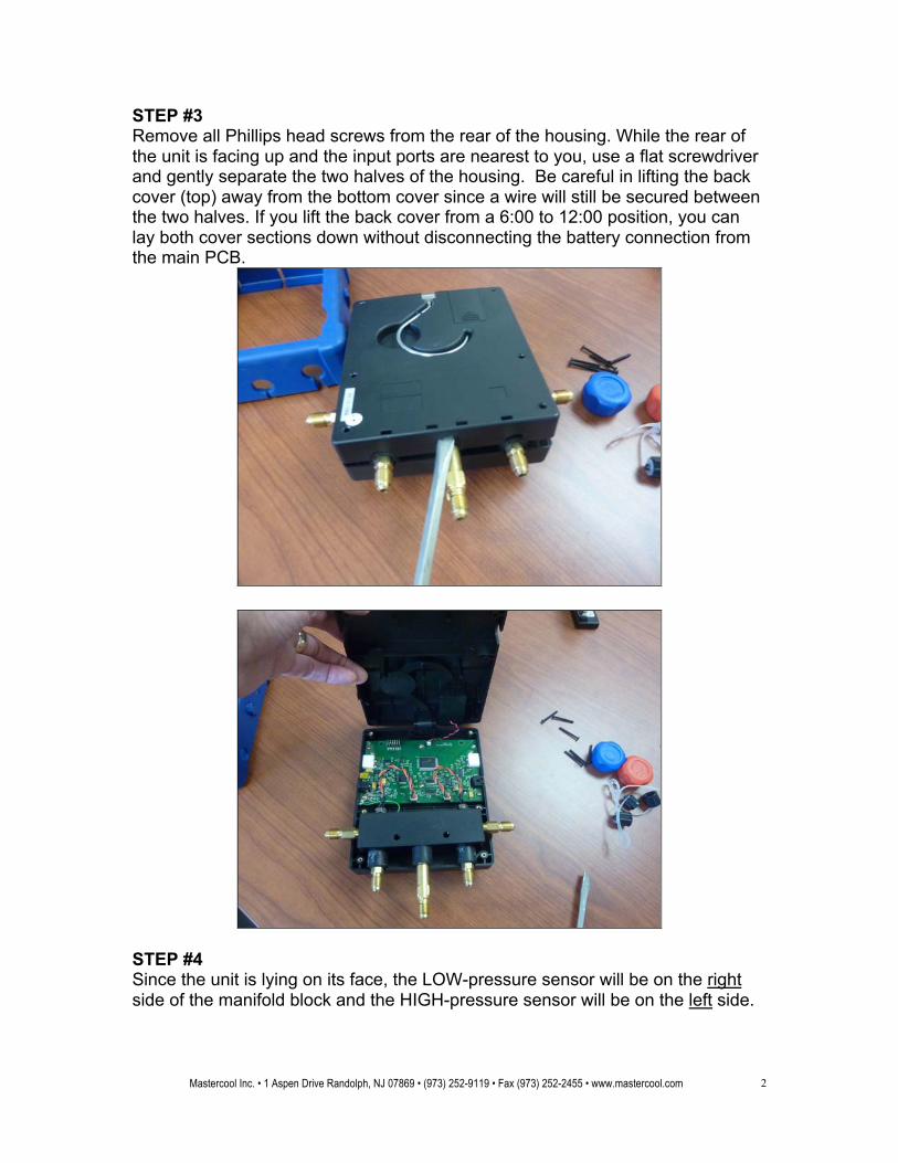
STEP #3 Remove all Phillips head screws from the rear of the housing. While the rear of the unit is facing up and the input ports are nearest to you, use a flat screwdriver and gently separate the two halves of the housing. Be careful in lifting the back cover (top) away from the bottom cover since a wire will still be secured between the two halves. If you lift the back cover from a 6:00 to 12:00 position, you can lay both cover sections down without disconnecting the battery connection from the main PCB.
STEP #4 Since the unit is lying on its face, the LOW-pressure sensor will be on the right side of the manifold block and the HIGH-pressure sensor will be on the left side.
Mastercool Inc. • 1 Aspen Drive Randolph, NJ 07869 • (973) 252-9119 • Fax (973) 252-2455 • www.mastercool.com
3
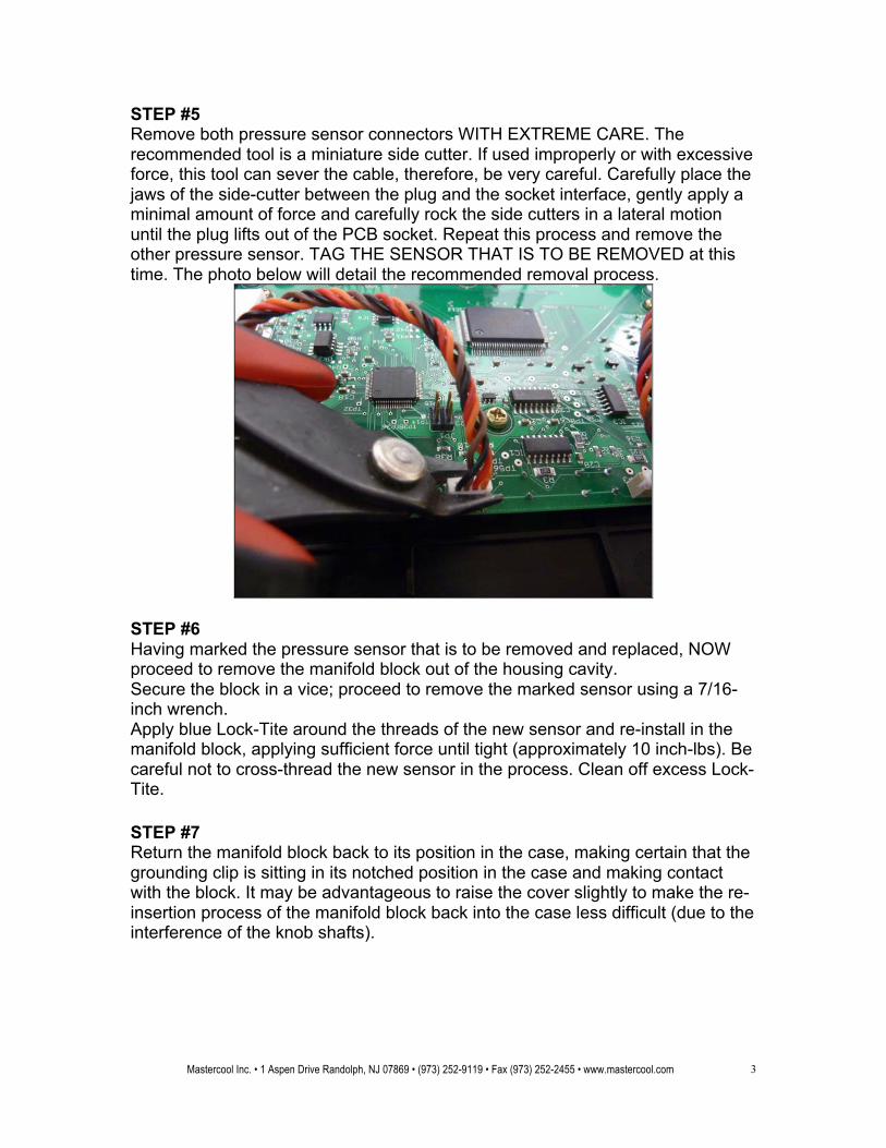
STEP #5 Remove both pressure sensor connectors WITH EXTREME CARE. The recommended tool is a miniature side cutter. If used improperly or with excessive force, this tool can sever the cable, therefore, be very careful. Carefully place the jaws of the side-cutter between the plug and the socket interface, gently apply a minimal amount of force and carefully rock the side cutters in a lateral motion until the plug lifts out of the PCB socket. Repeat this process and remove the other pressure sensor. TAG THE SENSOR THAT IS TO BE REMOVED at this time. The photo below will detail the recommended removal process.
STEP #6 Having marked the pressure sensor that is to be removed and replaced, NOW proceed to remove the manifold block out of the housing cavity. Secure the block in a vice; proceed to remove the marked sensor using a 7/16-inch wrench. Apply blue Lock-Tite around the threads of the new sensor and re-install in the manifold block, applying sufficient force until tight (approximately 10 inch-lbs). Be careful not to cross-thread the new sensor in the process. Clean off excess Lock-Tite. STEP #7 Return the manifold block back to its position in the case, making certain that the grounding clip is sitting in its notched position in the case and making contact with the block. It may be advantageous to raise the cover slightly to make the re-insertion process of the manifold block back into the case less difficult (due to the interference of the knob shafts).
Mastercool Inc. • 1 Aspen Drive Randolph, NJ 07869 • (973) 252-9119 • Fax (973) 252-2455 • www.mastercool.com
4
STEP #8 Reconnect each pressure sensor to its respective connector on the PCB. The black wire should be on the left side in each connector, when the manifold block is facing you. It is recommended that additional (slight) pressure be exerted on each side of the connector to ascertain that the connectors are inserted all the way. STEP #9 Carefully join both front and back covers together, making certain that the hinge lock cover (between front & back covers) is properly positioned before securing the covers with the screws. Check to make certain that the unit turns ON before tightening the screws. Tighten all screws that were removed in step # 3, until all surfaces around the perimeter of the case are touching firmly. If the unit does NOT turn ON, open the case and verify that the battery connector is not damaged and the connection with the battery is verified. STEP #10 IT MAY BE ADVANTAGEOUS TO BEGIN THE INSTALLATION OF THE COVER FROM THE REAR OF THE UNIT, STARTING WITH THE SIDE WHERE THE PORTS ARE LOCATED. Work the cover around the ports, followed by the bottom corners and finally pull the other sides over their corners. Insert the four (4) rubber “feet” back into the rectangular holes in the backside of the case.
STEP #11 You are now ready to re-calibrate the manifold with the newly installed pressure sensor. Follow the instructions entitled “PRESSURE SENSOR RE-CALIBRATION INSTRUCTIONS”.
Mastercool Inc. • 1 Aspen Drive Randolph, NJ 07869 • (973) 252-9119 • Fax (973) 252-2455 • www.mastercool.com
1
HOW TO REPLACE A PRESSURE SENSOR IN A 4-WAY DIGITAL MANIFOLD IN THE FIELD
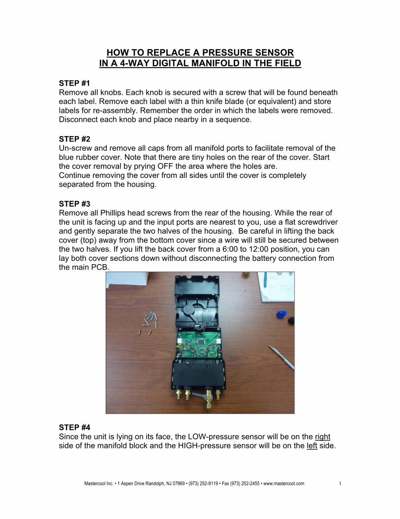
STEP #1 Remove all knobs. Each knob is secured with a screw that will be found beneath each label. Remove each label with a thin knife blade (or equivalent) and store labels for re-assembly. Remember the order in which the labels were removed. Disconnect each knob and place nearby in a sequence. STEP #2 Un-screw and remove all caps from all manifold ports to facilitate removal of the blue rubber cover. Note that there are tiny holes on the rear of the cover. Start the cover removal by prying OFF the area where the holes are. Continue removing the cover from all sides until the cover is completely separated from the housing. STEP #3 Remove all Phillips head screws from the rear of the housing. While the rear of the unit is facing up and the input ports are nearest to you, use a flat screwdriver and gently separate the two halves of the housing. Be careful in lifting the back cover (top) away from the bottom cover since a wire will still be secured between the two halves. If you lift the back cover from a 6:00 to 12:00 position, you can lay both cover sections down without disconnecting the battery connection from the main PCB.
STEP #4 Since the unit is lying on its face, the LOW-pressure sensor will be on the right side of the manifold block and the HIGH-pressure sensor will be on the left side.
Mastercool Inc. • 1 Aspen Drive Randolph, NJ 07869 • (973) 252-9119 • Fax (973) 252-2455 • www.mastercool.com
2
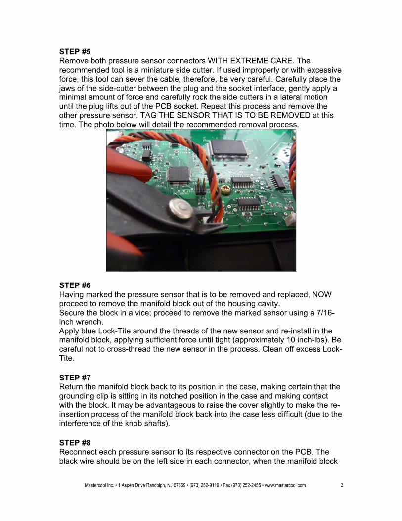
STEP #5 Remove both pressure sensor connectors WITH EXTREME CARE. The recommended tool is a miniature side cutter. If used improperly or with excessive force, this tool can sever the cable, therefore, be very careful. Carefully place the jaws of the side-cutter between the plug and the socket interface, gently apply a minimal amount of force and carefully rock the side cutters in a lateral motion until the plug lifts out of the PCB socket. Repeat this process and remove the other pressure sensor. TAG THE SENSOR THAT IS TO BE REMOVED at this time. The photo below will detail the recommended removal process.
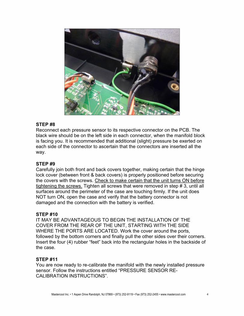
STEP #6 Having marked the pressure sensor that is to be removed and replaced, NOW proceed to remove the manifold block out of the housing cavity. Secure the block in a vice; proceed to remove the marked sensor using a 7/16-inch wrench. Apply blue Lock-Tite around the threads of the new sensor and re-install in the manifold block, applying sufficient force until tight (approximately 10 inch-lbs). Be careful not to cross-thread the new sensor in the process. Clean off excess Lock-Tite. STEP #7 Return the manifold block back to its position in the case, making certain that the grounding clip is sitting in its notched position in the case and making contact with the block. It may be advantageous to raise the cover slightly to make the re-insertion process of the manifold block back into the case less difficult (due to the interference of the knob shafts). STEP #8 Reconnect each pressure sensor to its respective connector on the PCB. The black wire should be on the left side in each connector, when the manifold block
Mastercool Inc. • 1 Aspen Drive Randolph, NJ 07869 • (973) 252-9119 • Fax (973) 252-2455 • www.mastercool.com
3
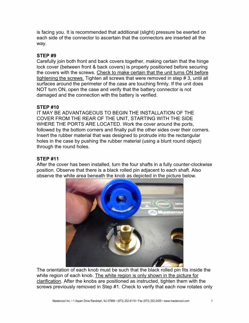
is facing you. It is recommended that additional (slight) pressure be exerted on each side of the connector to ascertain that the connectors are inserted all the way. STEP #9 Carefully join both front and back covers together, making certain that the hinge lock cover (between front & back covers) is properly positioned before securing the covers with the screws. Check to make certain that the unit turns ON before tightening the screws. Tighten all screws that were removed in step # 3, until all surfaces around the perimeter of the case are touching firmly. If the unit does NOT turn ON, open the case and verify that the battery connector is not damaged and the connection with the battery is verified. STEP #10 IT MAY BE ADVANTAGEOUS TO BEGIN THE INSTALLATION OF THE COVER FROM THE REAR OF THE UNIT, STARTING WITH THE SIDE WHERE THE PORTS ARE LOCATED. Work the cover around the ports, followed by the bottom corners and finally pull the other sides over their corners. Insert the rubber material that was designed to protrude into the rectangular holes in the case by pushing the rubber material (using a blunt round object) through the round holes. STEP #11 After the cover has been installed, turn the four shafts in a fully counter-clockwise position. Observe that there is a black rolled pin adjacent to each shaft. Also observe the white area beneath the knob as depicted in the picture below.
The orientation of each knob must be such that the black rolled pin fits inside the white region of each knob. The white region is only shown in the picture for clarification. After the knobs are positioned as instructed, tighten them with the screws previously removed in Step #1. Check to verify that each now rotates only
Mastercool Inc. • 1 Aspen Drive Randolph, NJ 07869 • (973) 252-9119 • Fax (973) 252-2455 • www.mastercool.com
4
90 degrees. If more than 90 degrees, turn the knob fully counter-clockwise remove and flip the knob 180 degree. Place the respective labels into their knob centers and apply a gentle force to secure them in place. STEP #12 You are now ready to re-calibrate the manifold with the newly installed pressure sensor. Follow the instructions entitled “PRESSURE SENSOR RECALIBRATION INSTRUCTIONS”.