Embed Size (px)
Citation preview

REMOTE MONITORING AND CONTROLGCP RMCSDocument No.: 10-100-R1Sheet: 1 of 9
German Cathodic Protection
GCP RMCS
is the remote monitoring and control system for cathodic corrosion protection stations.
Remote monitoring and control?
...As if you would be on site and have everything under control!
Independend, how far you are away from the location of the cathodic protection stations, it is always ensured that your systems are monitored and controlled.
How does it work?
The remote monitoring and control technique enables the remote supervision of separated technical systems with the help of the communication technology.
The fundamental functions of GCP RMCS can be subdi-veded into several subranges, like entering and alarming, switching, controlling and adjusting, as well as long-term archiving of all system relevant operational data of the connected cathodic protection stations.
If you want to reduce the operating cost
If you want to achieve the perfect transparency of your systems
If you want to reduce travel costs associated with traditional regular maintenance methods
When do you need GCP RMCS?
For the application in the cathodic protectiontechnique
Recording of measurements(current, voltage, potential)
Monitoring of analog limiting values (e.g. potential)
Logging and storage of events(status signals and fault signals)
Digital and analog transmission of measured values to the central station
Visualization of status and measured values online on monitor
Online parametrization of cathodic protection stations
Automatic and manual output of operating journal, routine fault signals, logging and diagrams on monitor and printer
If you want to avoid consequential damages caused by uneffective cathodic protection stations

REMOTE MONITORING AND CONTROLGCP RMCSDocument No.: 10-100-R1Sheet: 2 of 9
German Cathodic Protection
GCP RMCS essentially consists of two main compo-nents:
A control and monitoring unit, called CCOR, installed inside the transformer rectifier / alternative power unit or (in case of upgrading without enough space inside the cabinet) at the existing transformer rectifier / alternative power unit.
RMCS software package which monitor and control unlimited cathodic protection stations domestic or worldwide located (independent from borders or distances).
The connection between the two main components is made by a data transfer unit (e.g. direct wiring, fiber optic/SCADA, radio relay link modem, dial line modem, GSM modem (mobile phone), process field bus (profibus, inter-bus-s, can-bus, ...), satellite connection or a combination of these media. To control and monitor existing transformer rectifier remotely, it needs upgrade of rectifier hardware.
direct interwiringfiber optic/SCADA
radio relay link modemGSM modem (mobile phone)
process field bussatellite modem
T/R unit
T/R unit
T/R unit
Solar unitIntegrated RMCS unit includes the following main components:
Application of REMOTE MONITORING AND CON-TROL for Cathodic Protection Rectifiers
Antenna*
Surge Protection
Corrocontrol Output Regulator
Data transfer unit
RMCS Unit Transformer Rectifier
CCOR - Corrocontrol Output Regulator (programmable) 4 surge protected analog inputs (min.) 4 digital inputs 4 digital outputs relay contact for current interrupt mode
Data transfer unitOptionally antenna complete with cableSurge protection for antennaGPS synchronized Power interruption as optionPower supply: 85 - 240 VAC9 - 36 VDC UPS battery (optional)
RMCS unit (outside existing transformer rectifier) includes the following main components:
Stainless steel enclosure IP 54CCOR - Corrocontrol Output Regulator (programmable) 4 surge protected analog inputs (min.) 4 digital inputs 4 digital outputs relay contact for current interrupt mode
Data transfer unitOptionally antenna complete with cableSurge protection for antennaGPS synchronized Power interruption as optionPower supply: 85 - 240 VAC9 - 36 VDC UPS battery (optional)
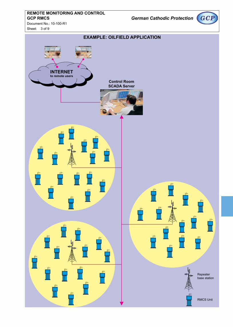
REMOTE MONITORING AND CONTROLGCP RMCSDocument No.: 10-100-R1Sheet: 3 of 9
German Cathodic Protection
Control RoomSCADA Server
INTERNETto remote users
Repeaterbase station
RMCS Unit
ExAMPLE: OILFIELD APPLICATION

REMOTE MONITORING AND CONTROLCorrocontrol Output Regulator (CCOR)Document No.: 10-100-R1Sheet: 4 of 9
German Cathodic Protection
General
CORROCONTROL OUTPUT REGULATOR (CCOR) is a control unit specially designed for the requirements of cathodic protection systems.CCOR can be used in all different cathodic protection applications like pipeline protection, well casing protection, plant protection internal and external protection of tanks, protection of off-shore structures, protection of steel in concrete, etc..The main task of CCOR is the monitoring and control of impressed current systems like transformer-rectifiers or DC/DC units.CCOR could be operated as a stand alone system with all parameters adjustable using push buttons and display on the controller, or via serial link from remote desktop computer.Different CCOR units can be connected to one single central computer for a network in order to control every CCOR unit from one central monitoring and control station.
Basics
CCOR consists of a 19” slide in box with an operating panel at the front side and a terminal plug at the back side.The CCOR can be used in applications where a new or existing power source for a cathodic protection impressed current system shall be monitored and controlled.CCOR provides the possibility to control systems via control signal of 0-5 VDC or 0/4-20 mA current loop to adjust the output voltage of the power source. As an option CCOR provides the control of systems with a motor drivenauto-transformer.CCOR measures continuously the output voltage, output current as well as the potential of up to two (2) connected reference electrodes (Cu/CuSO4, Ag/AgCl, Zinc or MnO2). The output voltage will be controlled respectively to the chosen control mode of either constant voltage, constant current or constant potential.If two reference cells are connected to CCOR and the Electrode IS mode is chosen, the unit checks these cells concerning their accuracy. In case that the difference of reference cells exceeds a preset limit, the unit recognises this fault, indicates this fault and switches to a so called “Intrinsic Safe (IS) Mode”, i.e. the control mode will be switched to a constant current mode as long as the failure has been fixed and acknowledged.This would avoid an overprotection on some structures like coated steel off-shore structures or prestressed steel armour in concrete, where hydrogen embitterment couldoccur if the potential becomes to negative.
+ _
CORROCONTROL POWER UNITControl Signal 0-5 V or 0/4-20 mV
Signal for ON/OFF Interrupter
DC Output Voltage
DC Output Current (Shunt)
Pot
entia
l 1
Pot
entia
l 2
+ O
utpu
t
- Out
put
DC Power Supply
ReferenceElectrodes
1 2 Anode Protected
Groundbed Object
Connection Scheme to DC/DC-Unit
System Layout
There are different possibilities to connect the CCOR with the main power unit (e.g. transformer rectifier, DC/DC converter).The CCOR could be installed inside of the same compart-ment as the main power unit or beside the main power unit.Figure 1 and figure 2 show some typical connection schemes.
Figure 1
Figure 2
CORROCONTROL POWER UNITControl Signal 0-5 V or 0/4-20 mV
Signal for ON/OFF Interrupter
DC Output Voltage
DC Output Current (Shunt)
Pot
entia
l 1
Pot
entia
l 2
+ O
utpu
t
- Out
put
AC Power Supply
ReferenceElectrodes
1 2 Anode Protected
Groundbed Object
Connection Scheme to Transformer Rectifier-Unit
+ _
RS232 / RS485
modbus protocol
RS232 / RS485
modbus protocol
German Cathodic Protection
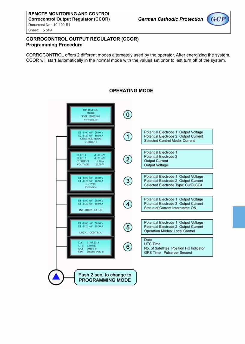
CORROCONTROL OUTPUT REGULATOR (CCOR)Programming Procedure
CORROCONTROL offers 2 different modes alternately used by the operator. After energizing the system, CCOR will start automatically in the normal mode with the values set prior to last turn off of the system.
OPERATING MODE
REMOTE MONITORING AND CONTROLCorrocontrol Output Regulator (CCOR)Document No.: 10-100-R1Sheet: 5 of 9

REMOTE MONITORING AND CONTROLCorrocontrol Output Regulator (CCOR)Document No.: 10-100-R1Sheet: 6 of 9
German Cathodic Protection
PROGRAMMING MODE PART 1
continued on next sheet 7 of 9

REMOTE MONITORING AND CONTROLCorrocontrol Output Regulator (CCOR)Document No.: 10-100-R1Sheet: 7 of 9
German Cathodic Protection
PROGRAMMING MODE PART 2

REMOTE MONITORING AND CONTROLCorrocontrol Output Regulator (CCOR)Document No.: 10-100-R1Sheet: 8 of 9
German Cathodic Protection
AC InputDC InputPower2 Potential Measurements (2 electrodes)Shunt MeasurementsVoltage MeasurementOutput, Control Signal (Ust)Output, Potential MeterRelay contact for current interrupt modeRS232 / RS485 Baud RateRS232 / RS485 ProtocolRS232 / RS485 HandshakeLCD Display CharactersLCD Display Size of CharacterDimensionsWeightOperation Temperature
115 - 230 V, 50/60 Hz12 - 48 V< 5.0 W(-4 V) - (+4 V) DC, > 10 MΩ, potential free0 - 60 mV, 0 - 100 mV0 - 60 V0 - 5 V DC0 - 4 V DC8 A9600 bit/s8N1None4 rows with 16 characters / LEDapprox. 5 mm170 x 140 x 130 mmapprox. 0.90 kg-10 °C to +55 °C
Specifications
REMOTE MONITORING AND CONTROLGCP RMCSDocument No.: 10-100-R1Sheet: 9 of 9
German Cathodic Protection
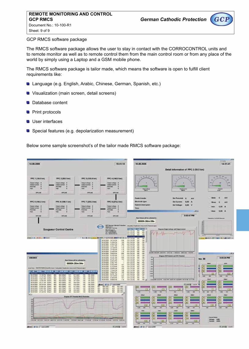
GCP RMCS software package
The RMCS software package allows the user to stay in contact with the CORROCONTROL units and to remote monitor as well as to remote control them from the main control room or from any place of the world by simply using a Laptop and a GSM mobile phone.
The RMCS software package is tailor made, which means the software is open to fulfill client requirements like:
Language (e.g. English, Arabic, Chinese, German, Spanish, etc.)
Visualization (main screen, detail screens)
Database content
Print protocols
User interfaces
Special features (e.g. depolarization measurement)
Below some sample screenshot’s of the tailor made RMCS software package:
REMOTE MONITORING AND CONTROLMiniTrans Wireless Remote MonitoringDocument No.: 10-010-R0Sheet: 1 of 4
German Cathodic Protection
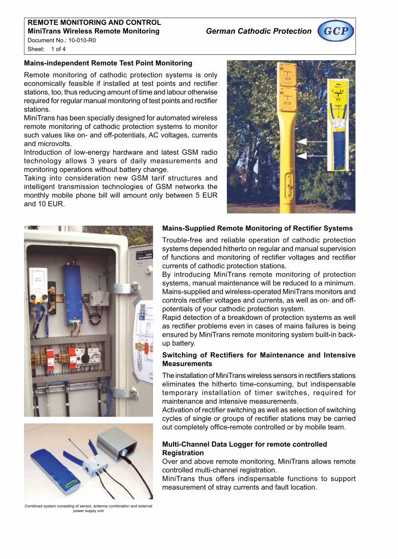
Mains-independent Remote Test Point MonitoringRemote monitoring of cathodic protection systems is only economically feasible if installed at test points and rectifier stations, too, thus reducing amount of time and labour otherwise required for regular manual monitoring of test points and rectifier stations. MiniTrans has been specially designed for automated wireless remote monitoring of cathodic protection systems to monitor such values like on- and off-potentials, AC voltages, currents and microvolts. Introduction of low-energy hardware and latest GSM radio technology allows 3 years of daily measurements and monitoring operations without battery change. Taking into consideration new GSM tarif structures and intelligent transmission technologies of GSM networks the monthly mobile phone bill will amount only between 5 EUR and 10 EUR.
Mains-Supplied Remote Monitoring of Rectifier SystemsTrouble-free and reliable operation of cathodic protection systems depended hitherto on regular and manual supervision of functions and monitoring of rectifier voltages and rectifier currents of cathodic protection stations. By introducing MiniTrans remote monitoring of protection systems, manual maintenance will be reduced to a minimum. Mains-supplied and wireless-operated MiniTrans monitors and controls rectifier voltages and currents, as well as on- and off- potentials of your cathodic protection system. Rapid detection of a breakdown of protection systems as well as rectifier problems even in cases of mains failures is being ensured by MiniTrans remote monitoring system built-in back-up battery.Switching of Rectifiers for Maintenance and Intensive MeasurementsThe installation of MiniTrans wireless sensors in rectifiers stations eliminates the hitherto time-consuming, but indispensable temporary installation of timer switches, required for maintenance and intensive measurements. Activation of rectifier switching as well as selection of switching cycles of single or groups of rectifier stations may be carried out completely office-remote controlled or by mobile team.
Multi-Channel Data Logger for remote controlled RegistrationOver and above remote monitoring, MiniTrans allows remote controlled multi-channel registration.MiniTrans thus offers indispensable functions to support measurement of stray currents and fault location.
Combined system consisting of sensor, antenna combination and externalpower supply unit
REMOTE MONITORING AND CONTROLMiniTrans Wireless Remote MonitoringDocument No.: 10-010-R0Sheet: 2 of 4
German Cathodic Protection
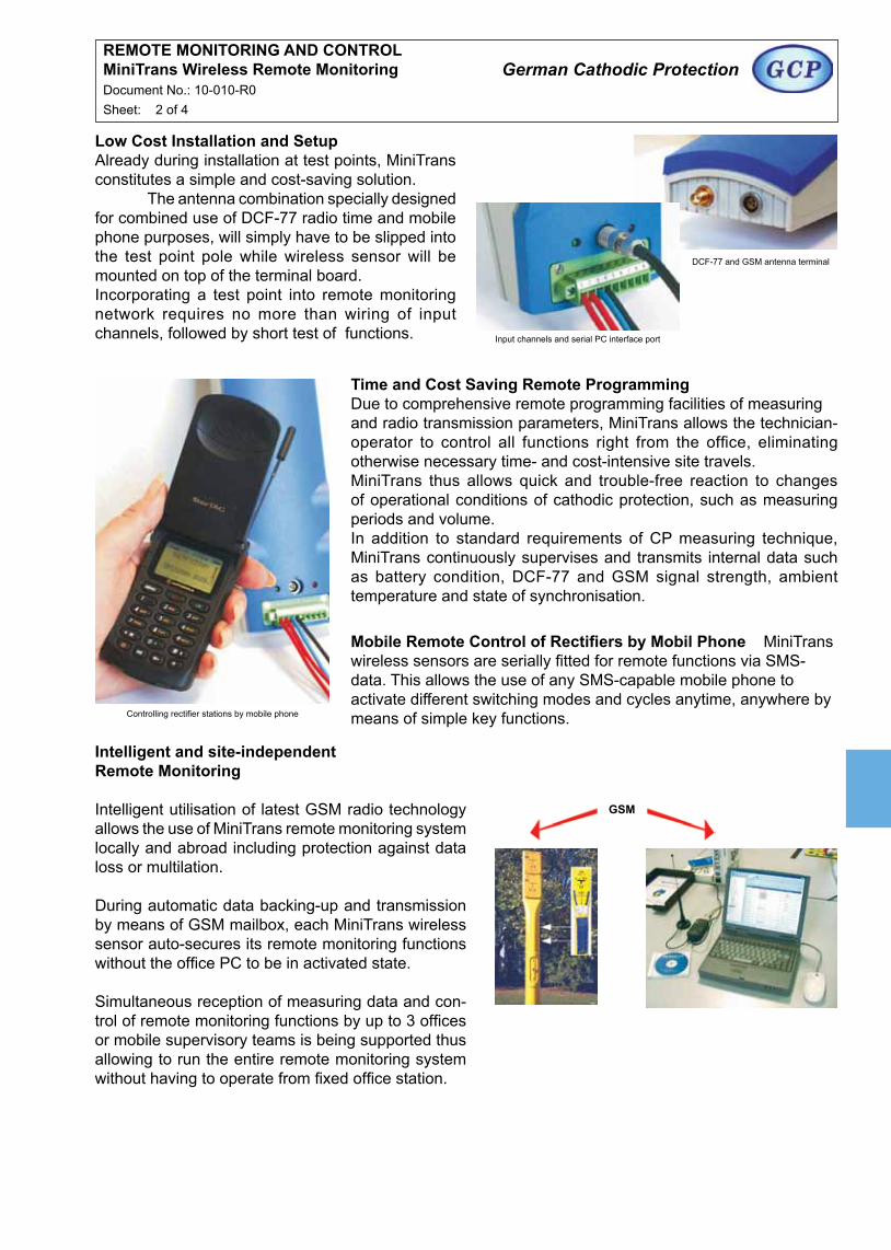
Low Cost Installation and SetupAlready during installation at test points, MiniTrans constitutes a simple and cost-saving solution. The antenna combination specially designed for combined use of DCF-77 radio time and mobile phone purposes, will simply have to be slipped into the test point pole while wireless sensor will be mounted on top of the terminal board.Incorporating a test point into remote monitoring network requires no more than wiring of input channels, followed by short test of functions. Input channels and serial PC interface port
DCF-77 and GSM antenna terminal
Time and Cost Saving Remote ProgrammingDue to comprehensive remote programming facilities of measuringand radio transmission parameters, MiniTrans allows the technician-operator to control all functions right from the office, eliminating otherwise necessary time- and cost-intensive site travels.MiniTrans thus allows quick and trouble-free reaction to changes of operational conditions of cathodic protection, such as measuring periods and volume.In addition to standard requirements of CP measuring technique, MiniTrans continuously supervises and transmits internal data such as battery condition, DCF-77 and GSM signal strength, ambient temperature and state of synchronisation.
Mobile Remote Control of Rectifiers by Mobil Phone MiniTrans wireless sensors are serially fitted for remote functions via SMS-data. This allows the use of any SMS-capable mobile phone to activate different switching modes and cycles anytime, anywhere by means of simple key functions.Controlling rectifier stations by mobile phone
Intelligent and site-independent Remote Monitoring
Intelligent utilisation of latest GSM radio technology allows the use of MiniTrans remote monitoring system locally and abroad including protection against data loss or multilation.
During automatic data backing-up and transmission by means of GSM mailbox, each MiniTrans wireless sensor auto-secures its remote monitoring functions without the office PC to be in activated state.
Simultaneous reception of measuring data and con-trol of remote monitoring functions by up to 3 offices or mobile supervisory teams is being supported thus allowing to run the entire remote monitoring system without having to operate from fixed office station.
GSM

Intelligent Remote Monitoring within Network
The aim to achieve intelligent and maintenance-free use of this remote monitoring system by consequent reduction of numbers of components, was also pursued in the design of the office equipment.
Reliable control and evaluation of test point and rectifier stations out of your office is being enabled by means of WinTrans radio modem, external radio antenna, as well as PC / Notebook-installed software WinTrans.
Linked with a network, all information regarding test points and rectifier stations of your entire organisation are handy at your fingertips.
REMOTE MONITORING AND CONTROLMiniTrans Wireless Remote MonitoringDocument No.: 10-010-R0Sheet: 3 of 4
German Cathodic Protection
WinTrans Software for Control and Evaluation of Remote Monitoring and Maintenance
The entire control and evaluation of MiniTrans wireless sensors is being effected by WinTrans software.
All parameters of current remote monitoring operations, like measuring ranges, measuring periods, radio transmission and switching cycles are being administrated by WinTrans and radioed to MiniTrans wireless sensors.
By means of a comprehensive and powerful database, optimally programmed to suit the monitoring require-ments of your cathodic protection system as well as those of your customers, WinTrans administers control and care of your entire CP test points and rectifier stations.

REMOTE MONITORING AND CONTROLMiniTrans Wireless Remote MonitoringDocument No.: 10-010-R0Sheet: 4 of 4
German Cathodic Protection
2 DC channels On / Off(e.g. potential and protection tube)2 AC channels(e.g. potential and foreign pipe)1 µV channel On / Off(e.g. pipe current or rectifier current)
Max. 4 complete on- and off measurements / day(timer free programmable)5, 10, 30, 60 or 120 min
Freely programmable(without or 1, 2, 4 or 8 min)
e.g. in case of interface measurementsStandard setting at remote monitoringe.g. 12/3 or 4/2 for intensive measurementFor pipe repair
Max. 4 complete on- and off measurements / day(timer free programmable)Every 5, 10, 30, 60, or 120 min
Quality and reception successesTimer deviation in msQuality and reception successesRemaining capacity and operational timeMains failure indicatorTemperature measurementsMonitoring measurements accuracy
All settings and measuring features arecompletely remote programmable
Approx. 2.5 to 3 yearsApprox. 3.5 to 4 years
Monitoring facilities
Measuring periods Mode normal
Mode diagnosis
Formation of mean value
Switching options Permanent On Measuring Cycle Permanent Cycle Permanent Off
Radio periods Mode normal
Mode diagnosis
Status monitoring DCF-77 Signal Synchronisation Radio signal Battery state Main power supply Temperature Zero calibration
Remote programming
Battery life span Mode normal Radio on weekends off
Remote Monitoring / Switching of Rectifier Station
Battery operated wireless sensor for radio-controlled monitoringand registration of CP-measuring data and for remote controlledswitching of rectifier station
2 x DC (with high AC attenuation)2 x AC (parallel to DC channel measuring)1 x µV (with high AC attenuation)
32 KByte Program / 96 KByte Data
9600 Baud serial for programming and supervision on installation site
DCF-77synchronised real time clock with supply voltage change-overand active temperature compensation
50 ms max. at 12 DCF receiver sequences / day (between -20°C and 60°C)
30 V / 0.1 A / 30(higher load with external power supply unit)
Internal radio modem for GSM networks at 900 MHz
Special antenna combination for DCF and GSM-radio applicationfor test point mounting or rectifier station installation
Wireless via remote transmission or direct via serial interface
Via serial interface with notebook on site
Lithium battery pack 7,2 V / 13 Ah(uninterrupted data safety during battery change)
External power supply unit with slave relais control
65 x 240 x 40 mm (W x H x D) / 480 g (incl. Battery)
75 x 60 x 40 mm (W x H x D) / 170 g (excl. Antenna rod)
Description
Measuring Inputs
Memory
Interface
Timer
Timer Deviation
Switching Load Output
Wireless system
Antenna
Program Updates
Calibration control QM
Battery Power Supply
Mains Power Supply (optional)
Dimensions / Weight
Wireless sensor
Antenna
Technical Data
Range± 1000 mV
± 10 V± 150 V
> 2 MΩ
Resolution0.1 mV1 mV15 V
Range1 V eff.10 V eff.250 V eff.
> 2 MΩ
15 - 500 Hz
Resolution0.2 mV2 mV50 V
60 dB (factor 1.000)100 dB (factor 100.000)
DC Voltage
Input Impedance
Damping at 16.6 Hz at 50.0 Hz
AC Voltage
Input Impedance
Frequency range
Microvolts
Input Impedance
Channel 1 + 2
Channel 1 + 2
Channel 3
Range± 100 mV
> 200 kΩ
Resolution1 µV
Damping at 16.6 Hz at 50.0 Hz
Zero calibration
60 dB (factor 1.000)100 dB (factor 100.000)
Automatic before measu-rement
Measuring Ranges
Registration / Data Logger
2 DC, 2 AC, 1 Microvolts
0,5 s, 1 s, 2 s, 5 s, 10 s, 30 s 2 s, 5 s, 10 s, 30 s
ca. 50.000 values
Number of channelsMeasuring rangeSampling rateStart-upTerminal time
Wireless by radioor direct via serial interface
all features remote programmable
Approx. 80 single channel recordingsat 1s sampling rate over 6 h(incl. radio transmission)
Automatic during registration
Channels
Sampling Rate without microvolts measurements with microvolts measurements
Measuring values memory
Programing
Data Transmission
Remote Programming
Battery Life Span
Zero calibration


![GCP & Go in 2015 [GCP編]](https://img.dokumen.tips/doc/110x75/58737f5a1a28ab272d8b474d/gcp-go-in-2015-gcp.jpg)


