Embed Size (px)
Citation preview
92011E_Ver6.2.fm/2 3 mars 2006
Remote control Impulse relays 0
Impulse relays are used for control by pushbuttons of lighting circuits:b incandescent lamps, low voltage halogen lamps, etc. (resistive loads)b fluorescent tubes, discharge lamps, etc. (inductive loads).
The range of Merlin Gerin impulse relays consists of:b TL+: high performance impulse relayb TL: impulse relays with auxiliariesb TLl: changeover impulse relays with auxiliariesb TLc, TLm, TLs: impulse relays with built-in auxiliary functions.
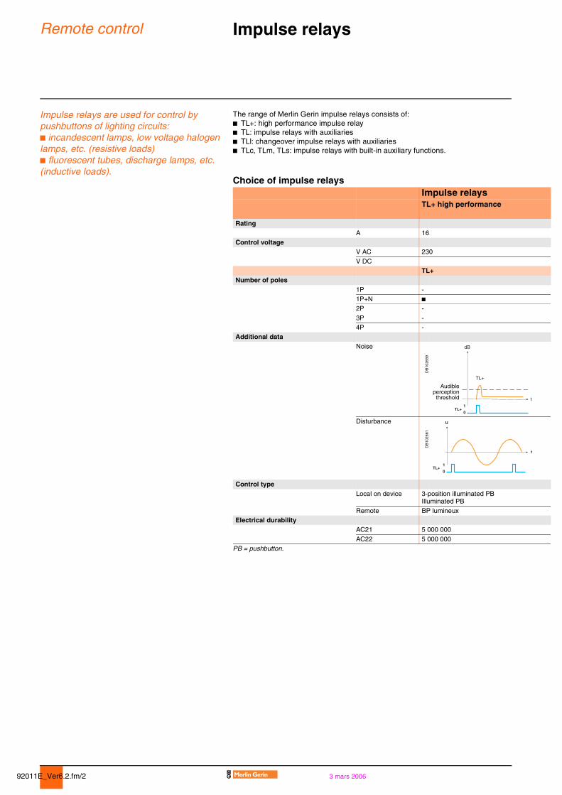
Choice of impulse relaysImpulse relaysTL+ high performance
RatingA 16
Control voltageV AC 230
V DCTL+
Number of poles1P -1P+N b2P -
3P -4P -
Additional dataNoise
DB
1026
59Disturbance
DB
1026
61
Control typeLocal on device 3-position illuminated PB
Illuminated PB
Remote BP lumineuxElectrical durability
AC21 5 000 000
AC22 5 000 000 PB = pushbutton.
dB
TL+
t
0
1TL+
Audibleperception
threshold
t
U
0
1TL+
92011E_Ver6.2.fm/33 mars 2006
Remote control Impulse relays 0
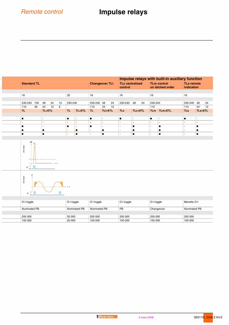
Impulse relays with built-in auxiliary functionStandard TL Changeover TLI TLc centralised
controlTLm control on latched order
TLs remote indication
16 32 16 16 16 16
230-240 130 48 24 12 230-240 230-240 48 24 230-240 48 24 230-240 230-240 48 24
110 48 24 12 6 110 24 12 110 110 24 12TL TL+ETL TL TL+ETL TL TLI+ETL TLc TLc+ETL TLm TLm+ETL TLs TLs+ETL
b - b - b - b - b - b -- - - - - - - - - - - -b - b - b - - b - b - bb b - b - b - b - b - bb b - b - b - b - b - b
DB
1026
60D
B10
2662
O-l toggle O-l toggle O-l toggle O-l toggle O-l toggle Manette O-I
Illuminated PB Illuminated PB Illuminated PB PB Changeover Illuminated PB
200 000 50 000 200 000 200 000 200 000 200 000
100 000 20 000 100 000 100 000 100 000 100 000
TLdB
t
0
1TL
t
U
0
1TL
92011E_Ver6.2.fm/4 3 mars 2006
Remote control Impulse relays 0
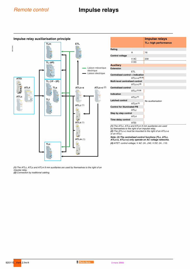
Impulse relay auxiliarisation principle Impulse relays
DB
1076
45
TL+ high performance
RatingA 16
Control voltageV AC 230V DC
AuxiliaryExtension
ETLCentralised control + indication
ATLc+s (2) (3)
Multi-level centralised controlATLc+c (3)
Centralised controlATLc (1) (3)
No auxiliarisation
IndicationATLs (1)
Latched controlATLm (1)
Control for illuminated PBATLz
Step by step controlATL4
Time delay controlATEt
(1) The ATLc, ATLs and ATLm 9 mm auxiliaries are used by themselves to the right of an impulse relay.(2) The ATLc+c must be mounted to the right of an ATLc+s or an ATLc.
Note: (3) The centralised control functions (TLc, ATLc, ATLc+s, ATLc+c) only operate on AC voltage networks.
(4) ATET: control voltage; V AC: 24...240, V DC: 24...110.
(1) The ATLc, ATLs and ATLm 9 mm auxiliaries are used by themselves to the right of an impulse relay.(2) Connection by traditional cabling.
92011E_Ver6.2.fm/53 mars 2006
Remote control Impulse relays 0
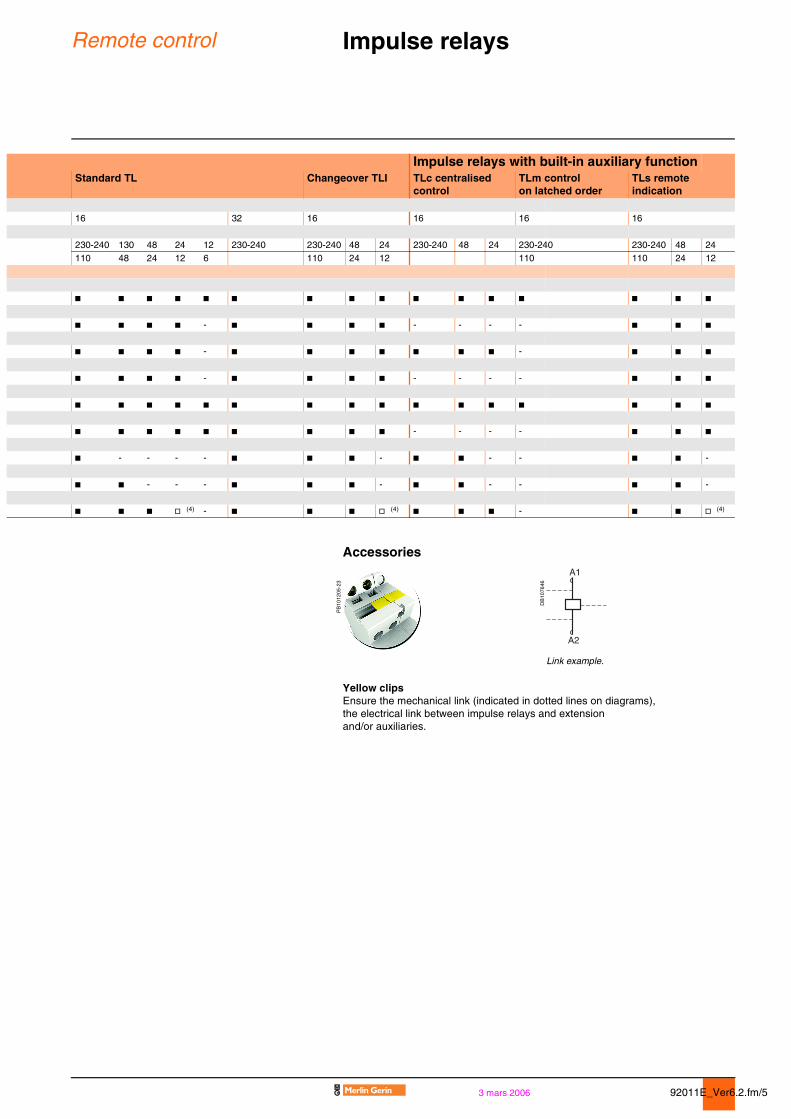
Impulse relays with built-in auxiliary functionStandard TL Changeover TLI TLc centralised
controlTLm control on latched order
TLs remote indication
16 32 16 16 16 16
230-240 130 48 24 12 230-240 230-240 48 24 230-240 48 24 230-240 230-240 48 24110 48 24 12 6 110 24 12 110 110 24 12
b b b b b b b b b b b b b b b b
b b b b - b b b b - - - - b b b
b b b b - b b b b b b b - b b b
b b b b - b b b b - - - - b b b
b b b b b b b b b b b b b b b b
b b b b b b b b b - - - - b b b
b - - - - b b b - b b - - b b -
b b - - - b b b - b b - - b b -
b b b v (4) - b b b v (4) b b b - b b v (4)
Accessories
PB
1012
05-2
3
DB
1076
46
Link example.
Yellow clipsEnsure the mechanical link (indicated in dotted lines on diagrams),the electrical link between impulse relays and extension and/or auxiliaries.
92011E_Ver6.2.fm/6 3 mars 2006
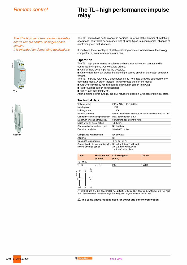
Remote control The TL+ high performance impulse relay 0
The TL+ high performance impulse relay allows remote control of single-phase circuits.It is intended for demanding applications
The TL+ allows high performance, in particular in terms of the number of switching operations, equivalent performance with all lamp types, minimum noise, absence of electromagnetic disturbances.
It combines the advantages of static switching and electromechanical technology: compact size, minimum temperature rise.
0620
08N
OperationThe TL+ high performance impulse relay has a normally open contact and is controlled by impulse type electrical orders.b One or more control points are possible.b On the front face, an orange indicator light comes on when the output contact is closed.The TL+ impulse relay has a pushbutton on its front face allowing selection of the operating mode. A green indicator light indicates the current mode:b ON/OFF control by room-mounted pushbutton (green light ON)b "ON" override (green light flashing)b "OFF" override (light OFF).After a mains power outage, the TL+ returns to position 0, whatever its initial state.
TL+
Technical data
PB
1001
51
Voltage rating 230 V AC (±10 %), 50 HzInrush power 11 VAHolding power 1.1 VA
Impulse duration 50 ms (recommended value for automation system: 200 ms)Control by illuminated pushbutton Max. consumption 5 mAMaximum switching frequency 6 switching operations/minute
Noise level on energisation < 30 dBACharacterisation on load types No derating
Electrical durability 5,000,000 cycles
Spacer Compliance with standard EN 669-2-2
Approval NFOperating temperature -5 °C to +55 °CConnection by tunnel terminals for flexible and rigid cables
Up to 2 x 1.5 mm2 with end2 x 2.5 mm2 without end1 x 4 mm2 without end
Type Width in mod. Coil voltage Uc Cat. no.of 9 mm (V CA)
TL+ 16 A1P+N 2+1 (1) 230 15032
DB
1061
56
(1) Comes with a 9 mm spacer (cat. no. 27062): to be used in case of mounting of the TL+ next to a circuit-breaker, contactor, impulse relay, etc. to guarantee optimum use.
d The same phase must be used for power and control connection.
1
2
3N L
4
A1
A2
92011E_Ver6.2.fm/73 mars 2006
Remote control 16 A TL and TLI impulse relays 0
OperationClosing of the impulse relay pole(s) is triggered by an impulse on the coil.Equipped in the factory with two stable mechanical positions, the pole(s) will be opened by the next impulse. Each impulse received by the coil reverses the position of the pole(s).b Manual controls on front face:v direct and priority manual control by O-l togglev disconnection of remote control by selector switch (except for single-piece TL)b Indication: mechanical on front face by toggle position.
Technical dataRating 16 A, cos ϕ = 0.6
Voltage rating 1P and 2P: 250 V, 50/60 Hz3P, 4P: 415 V, 50/60 Hz
Inrush power 1P and 2P: 19 VA3P, 4P: 38 VA
Remote control By pushbutton (illuminated up to 3 mA)Control voltage (Uc) Tolerance at 50 Hz: Uc +6 % -15 %
Tolerance at 60 Hz: Uc ±6 %Tolerance in DC: +6 % -10 %
Impulse duration 50 ms (recommended value for automation system: 200 ms)Maximum switching frequency 5 switching operations/minuteNoise level on energisation y 60 dBA (at 1 m)
Electrical durability 200,000 cycles (AC21)100,000 cycles (AC22)
Operating temperature -20 °C to +50 °CTropicalisation Treatment 2 (relative humidity 95 % at +55 °C)Connection Screw "±", Posidriv
Connection terminals Power circuit: tunnel terminals for cables up to 10 mm2
Control circuit: tunnel terminals for 0.5 to 6 mm2 cables
Compliance with standard EN 669-1, EN 669-2-2Approvals NF, CEBEC, IMQ, VDE, GOST
92011E_Ver6.2.fm/8 3 mars 2006
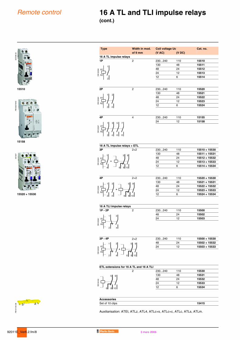
Remote control 16 A TL and TLI impulse relays (cont.) 0
0572
08-3
3
Type Width in mod. Coil voltage Uc Cat. no.of 9 mm (V AC) (V DC)
16 A TL impulse relays1P 2 230...240 110 15510
DB
1000
58
130 48 1551148 24 1551224 12 1551312 6 15514
15510 2P 2 230...240 110 15520
DB
1000
60
130 48 15521
PB
1000
74H
D
48 24 1552224 12 1552312 6 15524
4P 4 230...240 110 15155
DB
1000
67
24 12 15158
1515816 A TL impulse relays + ETL
0573
07
3P 2+2 230...240 110 15510 + 15530
DB
1000
63
130 48 15511 + 1553148 24 15512 + 1553224 12 15513 + 1553312 6 15514 + 15534
4P 2+2 230...240 110 15520 + 15530
DB
1000
65
130 48 15521 + 1553148 24 15522 + 1553224 12 15523 + 15533
15520 + 15530 12 6 15524 + 15534
16 A TLI impulse relays1P - 2P 2 230...240 110 15500
DB
1000
62
48 24 1550224 12 15503
3P - 4P 2+2 230...240 110 15500 + 15530
DB
1000
59
48 24 15502 + 1553224 12 15503 + 15533
ETL extensions for 16 A TL and 16 A TLI2 230...240 110 15530
DB
1061
60
130 48 1553148 24 1553224 12 1553312 6 15534
PB
1011
94-0
8
AccessoriesSet of 10 clips 15415
Auxiliarisation: ATEt, ATLz, ATL4, ATLc+s, ATLc+c, ATLc, ATLs, ATLm.
92011E_Ver6.2.fm/93 mars 2006
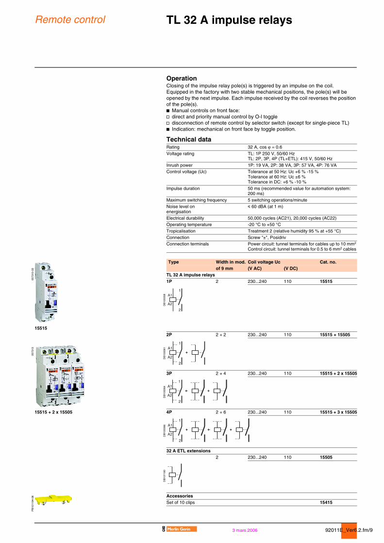
Remote control TL 32 A impulse relays 0
OperationClosing of the impulse relay pole(s) is triggered by an impulse on the coil.Equipped in the factory with two stable mechanical positions, the pole(s) will be opened by the next impulse. Each impulse received by the coil reverses the position of the pole(s).b Manual controls on front face:v direct and priority manual control by O-l togglev disconnection of remote control by selector switch (except for single-piece TL)b Indication: mechanical on front face by toggle position.
Technical dataRating 32 A, cos ϕ = 0.6
Voltage rating TL: 1P 250 V, 50/60 HzTL: 2P, 3P, 4P (TL+ETL): 415 V, 50/60 Hz
Inrush power 1P: 19 VA, 2P: 38 VA, 3P: 57 VA, 4P: 76 VAControl voltage (Uc) Tolerance at 50 Hz: Uc +6 % -15 %
Tolerance at 60 Hz: Uc ±6 %Tolerance in DC: +6 % -10 %
Impulse duration 50 ms (recommended value for automation system: 200 ms)
Maximum switching frequency 5 switching operations/minuteNoise level on energisation
y 60 dBA (at 1 m)
Electrical durability 50,000 cycles (AC21), 20,000 cycles (AC22)Operating temperature -20 °C to +50 °C
Tropicalisation Treatment 2 (relative humidity 95 % at +55 °C)Connection Screw "±", PosidrivConnection terminals Power circuit: tunnel terminals for cables up to 10 mm2
Control circuit: tunnel terminals for 0.5 to 6 mm2 cables
0573
10-3
3
Type Width in mod. Coil voltage Uc Cat. no.of 9 mm (V AC) (V DC)
TL 32 A impulse relays1P 2 230...240 110 15515
DB
1000
58
155152P 2 + 2 230...240 110 15515 + 15505
0573
13
DB
1000
61
3P 2 + 4 230...240 110 15515 + 2 x 15505
DB
1000
64
15515 + 2 x 15505 4P 2 + 6 230...240 110 15515 + 3 x 15505
DB
1000
66
32 A ETL extensions2 230...240 110 15505
DB
1011
80
PB
1011
94-0
8 AccessoriesSet of 10 clips 15415
92011E_Ver6.2.fm/10 3 mars 2006
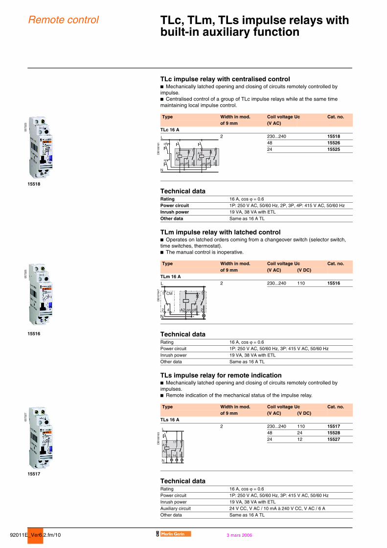
Remote control TLc, TLm, TLs impulse relays with built-in auxiliary function 0
TLc impulse relay with centralised controlb Mechanically latched opening and closing of circuits remotely controlled by impulse.b Centralised control of a group of TLc impulse relays while at the same time maintaining local impulse control.
0573
23
Type Width in mod. Coil voltage Uc Cat. no.of 9 mm (V AC)
TLc 16 A
DB
1061
61
2 230...240 1551848 1552624 15525
15518
Technical dataRating 16 A, cos ϕ = 0.6Power circuit 1P: 250 V AC, 50/60 Hz, 2P, 3P, 4P: 415 V AC, 50/60 HzInrush power 19 VA, 38 VA with ETL
Other data Same as 16 A TL
TLm impulse relay with latched controlb Operates on latched orders coming from a changeover switch (selector switch, time switches, thermostat).b The manual control is inoperative.
0573
25
Type Width in mod. Coil voltage Uc Cat. no.of 9 mm (V AC) (V DC)
TLm 16 A
DB
1076
47
2 230...240 110 15516
15516 Technical dataRating 16 A, cos ϕ = 0.6Power circuit 1P: 250 V AC, 50/60 Hz, 3P: 415 V AC, 50/60 Hz
Inrush power 19 VA, 38 VA with ETLOther data Same as 16 A TL
TLs impulse relay for remote indicationb Mechanically latched opening and closing of circuits remotely controlled by impulses.b Remote indication of the mechanical status of the impulse relay.
0573
27
Type Width in mod. Coil voltage Uc Cat. no.of 9 mm (V AC) (V DC)
TLs 16 A
DB
1061
63
2 230...240 110 1551748 24 1552824 12 15527
15517
Technical dataRating 16 A, cos ϕ = 0.6Power circuit 1P: 250 V AC, 50/60 Hz, 3P: 415 V AC, 50/60 Hz
Inrush power 19 VA, 38 VA with ETLAuxiliary circuit 24 V CC, V AC / 10 mA à 240 V CC, V AC / 6 AOther data Same as 16 A TL
L
N
off
offon
on
A111
2A2 A2
offon
A1
2
111
A2
A1
2
L
N12 14
92011E_Ver6.2.fm/113 mars 2006
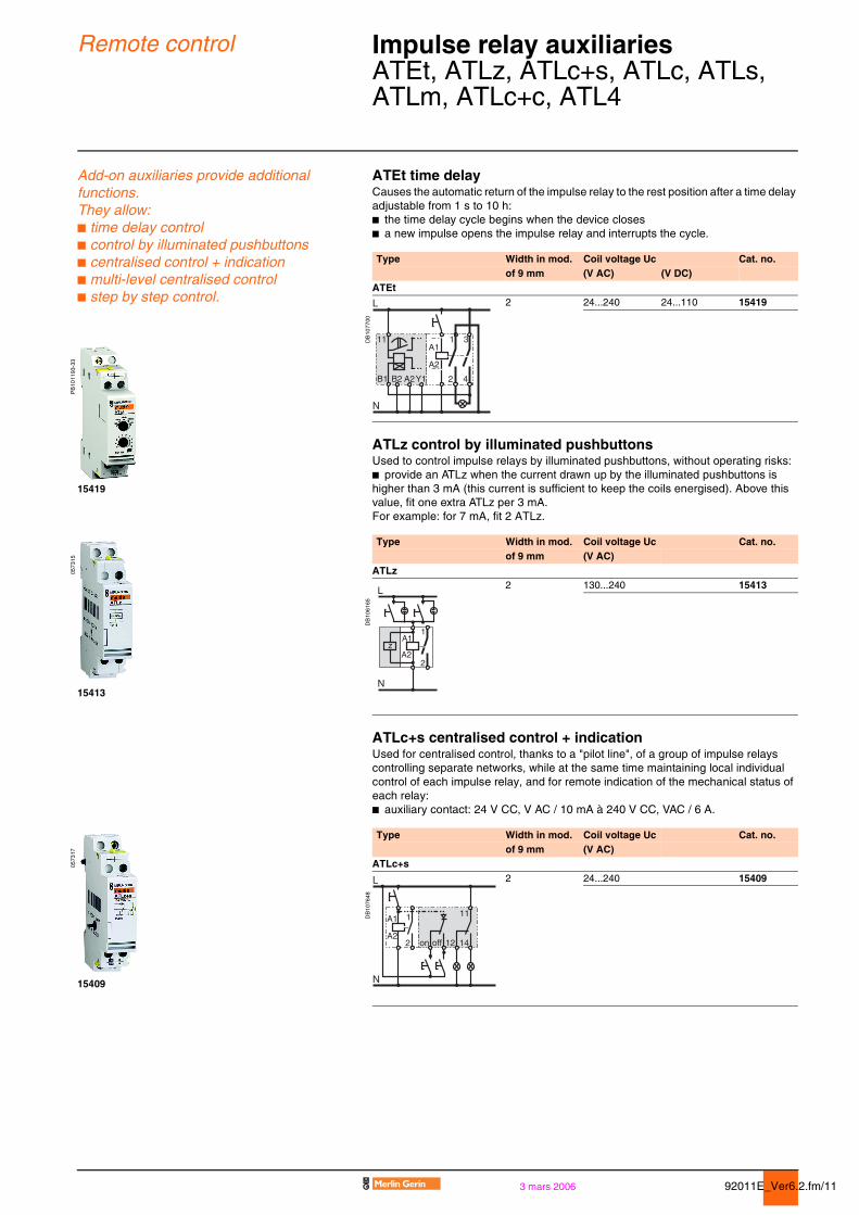
Remote control Impulse relay auxiliaries 0
ATEt, ATLz, ATLc+s, ATLc, ATLs, ATLm, ATLc+c, ATL4
Add-on auxiliaries provide additional functions.They allow:b time delay controlb control by illuminated pushbuttons b centralised control + indication b multi-level centralised controlb step by step control.
ATEt time delayCauses the automatic return of the impulse relay to the rest position after a time delay adjustable from 1 s to 10 h:b the time delay cycle begins when the device closesb a new impulse opens the impulse relay and interrupts the cycle.
Type Width in mod. Coil voltage Uc Cat. no.of 9 mm (V AC) (V DC)
ATEt
DB
1077
00
2 24...240 24...110 15419
PB
1011
93-3
3
ATLz control by illuminated pushbuttonsUsed to control impulse relays by illuminated pushbuttons, without operating risks:b provide an ATLz when the current drawn up by the illuminated pushbuttons is higher than 3 mA (this current is sufficient to keep the coils energised). Above this value, fit one extra ATLz per 3 mA.For example: for 7 mA, fit 2 ATLz.
15419
0573
15
Type Width in mod. Coil voltage Uc Cat. no.of 9 mm (V AC)
ATLz
DB
1061
65
2 130...240 15413
15413
ATLc+s centralised control + indicationUsed for centralised control, thanks to a "pilot line", of a group of impulse relays controlling separate networks, while at the same time maintaining local individual control of each impulse relay, and for remote indication of the mechanical status of each relay:b auxiliary contact: 24 V CC, V AC / 10 mA à 240 V CC, VAC / 6 A.
0573
17
Type Width in mod. Coil voltage Uc Cat. no.of 9 mm (V AC)
ATLc+s
DB
1076
48
2 24...240 15409
15409
1
A2
A1
2
z
L
N
92011E_Ver6.2.fm/12 3 mars 2006
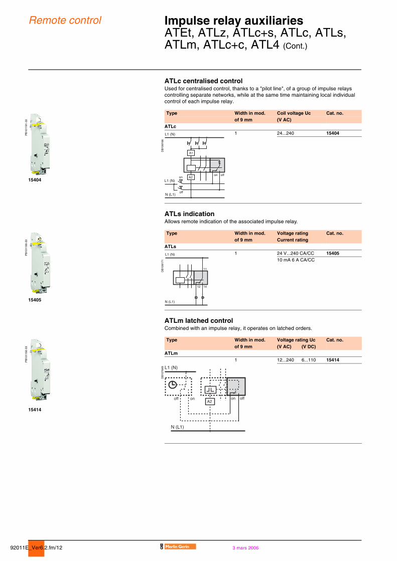
Remote control Impulse relay auxiliaries 0
ATEt, ATLz, ATLc+s, ATLc, ATLs, ATLm, ATLc+c, ATL4 (Cont.)
ATLc centralised controlUsed for centralised control, thanks to a "pilot line", of a group of impulse relays controlling separate networks, while at the same time maintaining local individual control of each impulse relay.
PB
1011
91-3
3
Type Width in mod. Coil voltage Uc Cat. no.of 9 mm (V AC)
ATLc
DB
1061
66
1 24...240 15404
15404
ATLs indicationAllows remote indication of the associated impulse relay.
PB
1011
90-3
3
Type Width in mod. Voltage rating Cat. no.of 9 mm Current rating
ATLs
DB
1061
71
1 24 V...240 CA/CC 1540510 mA 6 A CA/CC
15405
ATLm latched controlCombined with an impulse relay, it operates on latched orders.
PB
1011
92-3
3
Type Width in mod. Voltage rating Uc Cat. no.of 9 mm (V AC) (V DC)
ATLm
DB
1076
49
1 12...240 6...110 15414
15414
L1 (N)
N (L1)
L1 (N)
off
onon off
A1
A2
N (L1)
L1 (N)
12 14
11

92011E_Ver6.2.fm/133 mars 2006
Remote control Impulse relay auxiliaries 0
ATEt, ATLz, ATLc+s, ATLc, ATLs, ATLm, ATLc+c, ATL4 (Cont.)
ATLc+c multi-level centralised controlUsed to control the centralised controls of a number of impulse relay groups, while at the same time maintaining local individual control and centralised control by level:b each group, made up of TLc or (TL or TLl or TLs) + ATLc+s, must only contain a single ATLc+cb mounting: without mechanical link with impulse relays and auxiliaries.
0573
19
Type Width in mod. Coil voltage Uc Cat. no.of 9 mm (V AC)
ATLc+c
DB
1061
69
2 24...240 15410
15410
ATL4 step by step controlAllows the step by step sequence over 2 circuits:b the cycle is as follows:v 1st impulse - TL 1 closed, TL 2 openv 2nd impulse - TL 1 open, TL 2 closedv 3rd impulse - TL 1 and 2 closedv 4th impulse - TL 1 and 2 openv 5th impulse - TL 1 closed, TL 2 open, etc.b mounting: assembled between 2 impulse relays: according to the auxiliarisation table.
PB
1001
56
Type Width in mod. Coil voltage Uc Cat. no.of 9 mm (V AC) (V DC)
ATL4
DB
1061
70
4 230...240 110 15412
15412
AccessoriesYellow clipsEnsure the mechanical link (indicated in dotted lines on the diagrams) and/or the electrical link between impulse relays.
PB
1011
94-0
8
Type Cat. no.Set of 10 clips (spare) 15415
15415
A2
A1
L
N
1
off off offon
onon
2
A2
A1
A2
A1
A2
A1
L
TL1 TL2
N
1 1 1
2
2
2