Embed Size (px)
Citation preview
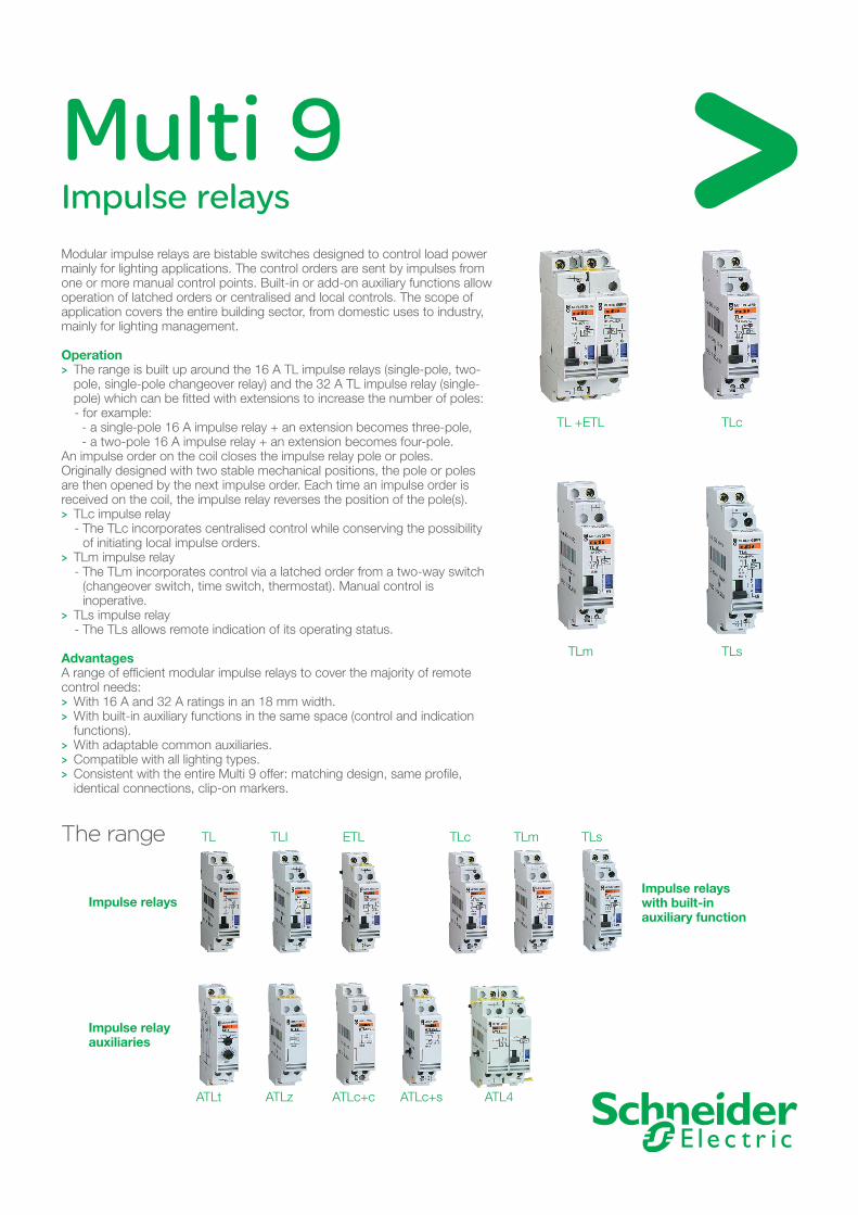
Multi 9Impulse relaysModular impulse relays are bistable switches designed to control load power mainly for lighting applications. The control orders are sent by impulses from one or more manual control points. Built-in or add-on auxiliary functions allow operation of latched orders or centralised and local controls. The scope of application covers the entire building sector, from domestic uses to industry, mainly for lighting management.
Operation The range is built up around the 16 A TL impulse relays (single-pole, two- >pole, single-pole changeover relay) and the 32 A TL impulse relay (single-pole) which can be fitted with extensions to increase the number of poles: - for example: - a single-pole 16 A impulse relay + an extension becomes three-pole, - a two-pole 16 A impulse relay + an extension becomes four-pole.
An impulse order on the coil closes the impulse relay pole or poles. Originally designed with two stable mechanical positions, the pole or poles are then opened by the next impulse order. Each time an impulse order is received on the coil, the impulse relay reverses the position of the pole(s).
TLc impulse relay >- The TLc incorporates centralised control while conserving the possibility
of initiating local impulse orders. TLm impulse relay >- The TLm incorporates control via a latched order from a two-way switch
(changeover switch, time switch, thermostat). Manual control is inoperative.
TLs impulse relay >- The TLs allows remote indication of its operating status.
Advantages A range of efficient modular impulse relays to cover the majority of remote control needs:
With 16 A and 32 A ratings in an 18 mm width. >With built-in auxiliary functions in the same space (control and indication >functions). With adaptable common auxiliaries. >Compatible with all lighting types. >Consistent with the entire Multi 9 offer: matching design, same profile, >identical connections, clip-on markers.
The range
Impulse relays
Impulse relay auxiliaries
TL +ETL TLc
TLm TLs
TL TLI ETL TLc TLm TLs
ATLt ATLz ATLc+c ATLc+s ATL4
Impulse relays with built-in auxiliary function
132371
Official approvalsCEBEC
ÖVE
SEMKO
VDE
UTE
KEMA KEUR
NEMKO
SETI
ASE
FI
E M AE U RK ÖVE
VD E
NF
Environment
Technical data
Choice table
Official approvals
SchematicdiagramsSchematicdiagrams
ImplementationImplementationc Designed for installation in all modular electrical switchboards andenclosures.c Easy to mount on symmetrical rail with bistable clip.c Easy to connect via serrated tunnel terminals with flap.c Captive screws with mixed +/- cavity.c Simplified clip-on addition of auxiliaries.
As standards, specifications and designs develop from time totime, always ask for confirmation of the information given inthis publication.Publication : Communication BT-S2ECreation, production: Sodipe (38)
Merlin GerinF-38050 Grenoble cedex 9tel. +33 (0)4 76 57 60 60telex : merge 320 842 F
Schneider Electric SA
03/00DIT E D1 97 012 enART. 078238
This document was printedon ecological paper.
TLc
TLc
1
A1
A2
2
R
L
N
BP
ON
BP
ONBP
OFF
TLc
A2
2
R
ON
1
A1
BP
OFF OFF
TLm
TLm
1
A2
2
R
L
N
ON
ON
OFF
OFF
TLs
TLs
1
A2
2
R
L
N
11
A1
BP
14
12
ONOFF
L
N
9
10
ETL
R
TL
R
BP
1
A2
2
A1
TL + ETL
L
N
1
A2
4
TLI
R
A1
BP
R
2
TLI
Choice tabletype width rating voltage coil cat. no.
in mod.of 9 mm V AC V DC
TL 16 A 2 16 230/240 110 155101P 130 48 15511
48 24 1551224 12 1551312 6 15514
2P 2 16 230/240 110 15520130 48 1552148 24 1552224 12 1552312 6 15524
3P 4 16 230/240 110 15510+15530130 48 15511+1553148 24 15512+1553224 12 15513+1553312 6 15514+15534
4P 4 16 230/240 110 15520+15530130 48 15521+1553148 24 15522+1553224 12 15523+1553312 6 15524+15534
TLI 16 A 2 16 230/240 110 155001P 48 24 15502ON/OFF 24 12 15503ETL 16 A 2 16 230/240 110 155302P 130 48 15531
48 24 1553224 12 1553312 6 15534
TL 32 A 1P 2 32 230/240 110 155152P 4 15515+155053P 6 15515+2x155054P 8 15515+3x15505ETL 32 A 1P 2 32 230/240 110 15505TLc 2 16 230/240 110 15518
48 1552624 15525
TLm 2 16 230/240 110 15516TLs 2 16 230/240 110 15517
M9F
P48
AE
N
Technical dataElectrical dataSpecific to 16 A TL, TLl, ETLc Power circuit:v rating: ln 16 A (cos ϕ = 0.6),v voltage:- single-pole and two-pole: 250 V - 50/60 Hz,three-pole, four-pole (TL+ETL): 415 V - 50/60 Hz.c Control circuit:v supply voltage:- 12 to 240 V AC - 50 Hz (+6%, -15%)/60 Hz (±6%)- 6 to 110 V DC (+6%, -10%),v inrush power:- single-pole and two-pole: 19 VA- three-pole and four-pole: 38 VA.c Electrical endurance:v 200 000 AC22 cycles (cos ϕ = 0.6),v 400 000 AC21 cycles (cos ϕ = 1).Specific to TLc, TLm, TLsc Power circuit:v rating: ln 16 A,v voltage: 250 V - 50/60 Hz.c Control circuit:v TLc: 24/48/230 to 240 V DC - 110 V AC,v TLm, TLs: 230 to 240 V DC - 110 V AC.c Electrical endurance: 200 000 cycles.Mechanical datac Connection: 0.5 to 6 mm2 cables.c Mechanical indication on front panrel viaoperating lever position.c Direct control on front face:v power: by ON-OFF lever,v coil isolation via switch.c Overall dimensions: h = 81; d = 64; l = 18 mm.Electrical data for the 32 A TLc Power circuit:v rating: ln 32 A (cos ϕ = 0.6),v voltage:- single-pole: 250 V - 50/60 Hz- two-pole, three-pole, four-pole: 415 V - 50/60 Hz.c Control circuit:v supply voltage:230/240 V AC - 50 Hz (+6%, -15%)/60 Hz (± 6%),v inrush power:- single-pole: 19 VA, two-pole: 38 VA- three-pole: 57 VA, four-pole: 76 VA.c Electrical endurance:v single-pole: 200 000 cycles,v two, three and four-pole: 100 000 cycles.Mechanical data for the 32 A TLc Connection:v power circuit: cables up to 10 mm2,v control circuit: 0.5 to 6 mm2 cables.c Same overall dimensions as the 16 A TL.
Environmentc Compliance with standards: NFC 61.110 /NFC 61.112 / IEC 669.1 / IEC 669.2.c Tropicalisation:treatment 2 (95% relative humidity at 55°C).c Class of protection:v case: IP40,v terminals: IP20.c Operating temperature:-20°C to + 50°C.c Storage temperature:-40°C to +80°C.c Switching noise level:≤ 60 dBA (at 1 metre).
L
N
1
A2
2
TL
R
A1
BP
TLTL
Official approvalsCEBEC
ÖVE
SEMKO
VDE
UTE
KEMA KEUR
NEMKO
SETI
ASE
FI
E M AE U RK ÖVE
VD E
NF
Environment
Technical data
Choice table
Official approvals
SchematicdiagramsSchematicdiagrams
ImplementationImplementationc Designed for installation in all modular electrical switchboards andenclosures.c Easy to mount on symmetrical rail with bistable clip.c Easy to connect via serrated tunnel terminals with flap.c Captive screws with mixed +/- cavity.c Simplified clip-on addition of auxiliaries.
As standards, specifications and designs develop from time totime, always ask for confirmation of the information given inthis publication.Publication : Communication BT-S2ECreation, production: Sodipe (38)
Merlin GerinF-38050 Grenoble cedex 9tel. +33 (0)4 76 57 60 60telex : merge 320 842 F
Schneider Electric SA
03/00DIT E D1 97 012 enART. 078238
This document was printedon ecological paper.
TLc
TLc
1
A1
A2
2
R
L
N
BP
ON
BP
ONBP
OFF
TLc
A2
2
R
ON
1
A1
BP
OFF OFF
TLm
TLm
1
A2
2
R
L
N
ON
ON
OFF
OFF
TLs
TLs
1
A2
2
R
L
N
11
A1
BP
14
12
ONOFF
L
N
9
10
ETL
R
TL
R
BP
1
A2
2
A1
TL + ETL
L
N
1
A2
4
TLI
R
A1
BP
R
2
TLI
Choice tabletype width rating voltage coil cat. no.
in mod.of 9 mm V AC V DC
TL 16 A 2 16 230/240 110 155101P 130 48 15511
48 24 1551224 12 1551312 6 15514
2P 2 16 230/240 110 15520130 48 1552148 24 1552224 12 1552312 6 15524
3P 4 16 230/240 110 15510+15530130 48 15511+1553148 24 15512+1553224 12 15513+1553312 6 15514+15534
4P 4 16 230/240 110 15520+15530130 48 15521+1553148 24 15522+1553224 12 15523+1553312 6 15524+15534
TLI 16 A 2 16 230/240 110 155001P 48 24 15502ON/OFF 24 12 15503ETL 16 A 2 16 230/240 110 155302P 130 48 15531
48 24 1553224 12 1553312 6 15534
TL 32 A 1P 2 32 230/240 110 155152P 4 15515+155053P 6 15515+2x155054P 8 15515+3x15505ETL 32 A 1P 2 32 230/240 110 15505TLc 2 16 230/240 110 15518
48 1552624 15525
TLm 2 16 230/240 110 15516TLs 2 16 230/240 110 15517
M9F
P48
AE
N
Technical dataElectrical dataSpecific to 16 A TL, TLl, ETLc Power circuit:v rating: ln 16 A (cos ϕ = 0.6),v voltage:- single-pole and two-pole: 250 V - 50/60 Hz,three-pole, four-pole (TL+ETL): 415 V - 50/60 Hz.c Control circuit:v supply voltage:- 12 to 240 V AC - 50 Hz (+6%, -15%)/60 Hz (±6%)- 6 to 110 V DC (+6%, -10%),v inrush power:- single-pole and two-pole: 19 VA- three-pole and four-pole: 38 VA.c Electrical endurance:v 200 000 AC22 cycles (cos ϕ = 0.6),v 400 000 AC21 cycles (cos ϕ = 1).Specific to TLc, TLm, TLsc Power circuit:v rating: ln 16 A,v voltage: 250 V - 50/60 Hz.c Control circuit:v TLc: 24/48/230 to 240 V DC - 110 V AC,v TLm, TLs: 230 to 240 V DC - 110 V AC.c Electrical endurance: 200 000 cycles.Mechanical datac Connection: 0.5 to 6 mm2 cables.c Mechanical indication on front panrel viaoperating lever position.c Direct control on front face:v power: by ON-OFF lever,v coil isolation via switch.c Overall dimensions: h = 81; d = 64; l = 18 mm.Electrical data for the 32 A TLc Power circuit:v rating: ln 32 A (cos ϕ = 0.6),v voltage:- single-pole: 250 V - 50/60 Hz- two-pole, three-pole, four-pole: 415 V - 50/60 Hz.c Control circuit:v supply voltage:230/240 V AC - 50 Hz (+6%, -15%)/60 Hz (± 6%),v inrush power:- single-pole: 19 VA, two-pole: 38 VA- three-pole: 57 VA, four-pole: 76 VA.c Electrical endurance:v single-pole: 200 000 cycles,v two, three and four-pole: 100 000 cycles.Mechanical data for the 32 A TLc Connection:v power circuit: cables up to 10 mm2,v control circuit: 0.5 to 6 mm2 cables.c Same overall dimensions as the 16 A TL.
Environmentc Compliance with standards: NFC 61.110 /NFC 61.112 / IEC 669.1 / IEC 669.2.c Tropicalisation:treatment 2 (95% relative humidity at 55°C).c Class of protection:v case: IP40,v terminals: IP20.c Operating temperature:-20°C to + 50°C.c Storage temperature:-40°C to +80°C.c Switching noise level:≤ 60 dBA (at 1 metre).
L
N
1
A2
2
TL
R
A1
BP
TL
TLI
Official approvalsCEBEC
ÖVE
SEMKO
VDE
UTE
KEMA KEUR
NEMKO
SETI
ASE
FI
E M AE U RK ÖVE
VD E
NF
Environment
Technical data
Choice table
Official approvals
SchematicdiagramsSchematicdiagrams
ImplementationImplementationc Designed for installation in all modular electrical switchboards andenclosures.c Easy to mount on symmetrical rail with bistable clip.c Easy to connect via serrated tunnel terminals with flap.c Captive screws with mixed +/- cavity.c Simplified clip-on addition of auxiliaries.
As standards, specifications and designs develop from time totime, always ask for confirmation of the information given inthis publication.Publication : Communication BT-S2ECreation, production: Sodipe (38)
Merlin GerinF-38050 Grenoble cedex 9tel. +33 (0)4 76 57 60 60telex : merge 320 842 F
Schneider Electric SA
03/00DIT E D1 97 012 enART. 078238
This document was printedon ecological paper.
TLc
TLc
1
A1
A2
2
R
L
N
BP
ON
BP
ONBP
OFF
TLc
A2
2
R
ON
1
A1
BP
OFF OFF
TLm
TLm
1
A2
2
R
L
N
ON
ON
OFF
OFF
TLs
TLs
1
A2
2
R
L
N
11
A1
BP
14
12
ONOFF
L
N
9
10
ETL
R
TL
R
BP
1
A2
2
A1
TL + ETL
L
N
1
A2
4
TLI
R
A1
BP
R
2
TLI
Choice tabletype width rating voltage coil cat. no.
in mod.of 9 mm V AC V DC
TL 16 A 2 16 230/240 110 155101P 130 48 15511
48 24 1551224 12 1551312 6 15514
2P 2 16 230/240 110 15520130 48 1552148 24 1552224 12 1552312 6 15524
3P 4 16 230/240 110 15510+15530130 48 15511+1553148 24 15512+1553224 12 15513+1553312 6 15514+15534
4P 4 16 230/240 110 15520+15530130 48 15521+1553148 24 15522+1553224 12 15523+1553312 6 15524+15534
TLI 16 A 2 16 230/240 110 155001P 48 24 15502ON/OFF 24 12 15503ETL 16 A 2 16 230/240 110 155302P 130 48 15531
48 24 1553224 12 1553312 6 15534
TL 32 A 1P 2 32 230/240 110 155152P 4 15515+155053P 6 15515+2x155054P 8 15515+3x15505ETL 32 A 1P 2 32 230/240 110 15505TLc 2 16 230/240 110 15518
48 1552624 15525
TLm 2 16 230/240 110 15516TLs 2 16 230/240 110 15517
M9F
P48
AE
N
Technical dataElectrical dataSpecific to 16 A TL, TLl, ETLc Power circuit:v rating: ln 16 A (cos ϕ = 0.6),v voltage:- single-pole and two-pole: 250 V - 50/60 Hz,three-pole, four-pole (TL+ETL): 415 V - 50/60 Hz.c Control circuit:v supply voltage:- 12 to 240 V AC - 50 Hz (+6%, -15%)/60 Hz (±6%)- 6 to 110 V DC (+6%, -10%),v inrush power:- single-pole and two-pole: 19 VA- three-pole and four-pole: 38 VA.c Electrical endurance:v 200 000 AC22 cycles (cos ϕ = 0.6),v 400 000 AC21 cycles (cos ϕ = 1).Specific to TLc, TLm, TLsc Power circuit:v rating: ln 16 A,v voltage: 250 V - 50/60 Hz.c Control circuit:v TLc: 24/48/230 to 240 V DC - 110 V AC,v TLm, TLs: 230 to 240 V DC - 110 V AC.c Electrical endurance: 200 000 cycles.Mechanical datac Connection: 0.5 to 6 mm2 cables.c Mechanical indication on front panrel viaoperating lever position.c Direct control on front face:v power: by ON-OFF lever,v coil isolation via switch.c Overall dimensions: h = 81; d = 64; l = 18 mm.Electrical data for the 32 A TLc Power circuit:v rating: ln 32 A (cos ϕ = 0.6),v voltage:- single-pole: 250 V - 50/60 Hz- two-pole, three-pole, four-pole: 415 V - 50/60 Hz.c Control circuit:v supply voltage:230/240 V AC - 50 Hz (+6%, -15%)/60 Hz (± 6%),v inrush power:- single-pole: 19 VA, two-pole: 38 VA- three-pole: 57 VA, four-pole: 76 VA.c Electrical endurance:v single-pole: 200 000 cycles,v two, three and four-pole: 100 000 cycles.Mechanical data for the 32 A TLc Connection:v power circuit: cables up to 10 mm2,v control circuit: 0.5 to 6 mm2 cables.c Same overall dimensions as the 16 A TL.
Environmentc Compliance with standards: NFC 61.110 /NFC 61.112 / IEC 669.1 / IEC 669.2.c Tropicalisation:treatment 2 (95% relative humidity at 55°C).c Class of protection:v case: IP40,v terminals: IP20.c Operating temperature:-20°C to + 50°C.c Storage temperature:-40°C to +80°C.c Switching noise level:≤ 60 dBA (at 1 metre).
L
N
1
A2
2
TL
R
A1
BP
TL
TL + ETL
Official approvalsCEBEC
ÖVE
SEMKO
VDE
UTE
KEMA KEUR
NEMKO
SETI
ASE
FI
E M AE U RK ÖVE
VD E
NF
Environment
Technical data
Choice table
Official approvals
SchematicdiagramsSchematicdiagrams
ImplementationImplementationc Designed for installation in all modular electrical switchboards andenclosures.c Easy to mount on symmetrical rail with bistable clip.c Easy to connect via serrated tunnel terminals with flap.c Captive screws with mixed +/- cavity.c Simplified clip-on addition of auxiliaries.
As standards, specifications and designs develop from time totime, always ask for confirmation of the information given inthis publication.Publication : Communication BT-S2ECreation, production: Sodipe (38)
Merlin GerinF-38050 Grenoble cedex 9tel. +33 (0)4 76 57 60 60telex : merge 320 842 F
Schneider Electric SA
03/00DIT E D1 97 012 enART. 078238
This document was printedon ecological paper.
TLc
TLc
1
A1
A2
2
R
L
N
BP
ON
BP
ONBP
OFF
TLc
A2
2
R
ON
1
A1
BP
OFF OFF
TLm
TLm
1
A2
2
R
L
N
ON
ON
OFF
OFF
TLs
TLs
1
A2
2
R
L
N
11
A1
BP
14
12
ONOFF
L
N
9
10
ETL
R
TL
R
BP
1
A2
2
A1
TL + ETL
L
N
1
A2
4
TLI
R
A1
BP
R
2
TLI
Choice tabletype width rating voltage coil cat. no.
in mod.of 9 mm V AC V DC
TL 16 A 2 16 230/240 110 155101P 130 48 15511
48 24 1551224 12 1551312 6 15514
2P 2 16 230/240 110 15520130 48 1552148 24 1552224 12 1552312 6 15524
3P 4 16 230/240 110 15510+15530130 48 15511+1553148 24 15512+1553224 12 15513+1553312 6 15514+15534
4P 4 16 230/240 110 15520+15530130 48 15521+1553148 24 15522+1553224 12 15523+1553312 6 15524+15534
TLI 16 A 2 16 230/240 110 155001P 48 24 15502ON/OFF 24 12 15503ETL 16 A 2 16 230/240 110 155302P 130 48 15531
48 24 1553224 12 1553312 6 15534
TL 32 A 1P 2 32 230/240 110 155152P 4 15515+155053P 6 15515+2x155054P 8 15515+3x15505ETL 32 A 1P 2 32 230/240 110 15505TLc 2 16 230/240 110 15518
48 1552624 15525
TLm 2 16 230/240 110 15516TLs 2 16 230/240 110 15517
M9F
P48
AE
N
Technical dataElectrical dataSpecific to 16 A TL, TLl, ETLc Power circuit:v rating: ln 16 A (cos ϕ = 0.6),v voltage:- single-pole and two-pole: 250 V - 50/60 Hz,three-pole, four-pole (TL+ETL): 415 V - 50/60 Hz.c Control circuit:v supply voltage:- 12 to 240 V AC - 50 Hz (+6%, -15%)/60 Hz (±6%)- 6 to 110 V DC (+6%, -10%),v inrush power:- single-pole and two-pole: 19 VA- three-pole and four-pole: 38 VA.c Electrical endurance:v 200 000 AC22 cycles (cos ϕ = 0.6),v 400 000 AC21 cycles (cos ϕ = 1).Specific to TLc, TLm, TLsc Power circuit:v rating: ln 16 A,v voltage: 250 V - 50/60 Hz.c Control circuit:v TLc: 24/48/230 to 240 V DC - 110 V AC,v TLm, TLs: 230 to 240 V DC - 110 V AC.c Electrical endurance: 200 000 cycles.Mechanical datac Connection: 0.5 to 6 mm2 cables.c Mechanical indication on front panrel viaoperating lever position.c Direct control on front face:v power: by ON-OFF lever,v coil isolation via switch.c Overall dimensions: h = 81; d = 64; l = 18 mm.Electrical data for the 32 A TLc Power circuit:v rating: ln 32 A (cos ϕ = 0.6),v voltage:- single-pole: 250 V - 50/60 Hz- two-pole, three-pole, four-pole: 415 V - 50/60 Hz.c Control circuit:v supply voltage:230/240 V AC - 50 Hz (+6%, -15%)/60 Hz (± 6%),v inrush power:- single-pole: 19 VA, two-pole: 38 VA- three-pole: 57 VA, four-pole: 76 VA.c Electrical endurance:v single-pole: 200 000 cycles,v two, three and four-pole: 100 000 cycles.Mechanical data for the 32 A TLc Connection:v power circuit: cables up to 10 mm2,v control circuit: 0.5 to 6 mm2 cables.c Same overall dimensions as the 16 A TL.
Environmentc Compliance with standards: NFC 61.110 /NFC 61.112 / IEC 669.1 / IEC 669.2.c Tropicalisation:treatment 2 (95% relative humidity at 55°C).c Class of protection:v case: IP40,v terminals: IP20.c Operating temperature:-20°C to + 50°C.c Storage temperature:-40°C to +80°C.c Switching noise level:≤ 60 dBA (at 1 metre).
L
N
1
A2
2
TL
R
A1
BP
TL
TLs
Official approvalsCEBEC
ÖVE
SEMKO
VDE
UTE
KEMA KEUR
NEMKO
SETI
ASE
FI
E M AE U RK ÖVE
VD E
NF
Environment
Technical data
Choice table
Official approvals
SchematicdiagramsSchematicdiagrams
ImplementationImplementationc Designed for installation in all modular electrical switchboards andenclosures.c Easy to mount on symmetrical rail with bistable clip.c Easy to connect via serrated tunnel terminals with flap.c Captive screws with mixed +/- cavity.c Simplified clip-on addition of auxiliaries.
As standards, specifications and designs develop from time totime, always ask for confirmation of the information given inthis publication.Publication : Communication BT-S2ECreation, production: Sodipe (38)
Merlin GerinF-38050 Grenoble cedex 9tel. +33 (0)4 76 57 60 60telex : merge 320 842 F
Schneider Electric SA
03/00DIT E D1 97 012 enART. 078238
This document was printedon ecological paper.
TLc
TLc
1
A1
A2
2
R
L
N
BP
ON
BP
ONBP
OFF
TLc
A2
2
R
ON
1
A1
BP
OFF OFF
TLm
TLm
1
A2
2
R
L
N
ON
ON
OFF
OFF
TLs
TLs
1
A2
2
R
L
N
11
A1
BP
14
12
ONOFF
L
N
9
10
ETL
R
TL
R
BP
1
A2
2
A1
TL + ETL
L
N
1
A2
4
TLI
R
A1
BP
R
2
TLI
Choice tabletype width rating voltage coil cat. no.
in mod.of 9 mm V AC V DC
TL 16 A 2 16 230/240 110 155101P 130 48 15511
48 24 1551224 12 1551312 6 15514
2P 2 16 230/240 110 15520130 48 1552148 24 1552224 12 1552312 6 15524
3P 4 16 230/240 110 15510+15530130 48 15511+1553148 24 15512+1553224 12 15513+1553312 6 15514+15534
4P 4 16 230/240 110 15520+15530130 48 15521+1553148 24 15522+1553224 12 15523+1553312 6 15524+15534
TLI 16 A 2 16 230/240 110 155001P 48 24 15502ON/OFF 24 12 15503ETL 16 A 2 16 230/240 110 155302P 130 48 15531
48 24 1553224 12 1553312 6 15534
TL 32 A 1P 2 32 230/240 110 155152P 4 15515+155053P 6 15515+2x155054P 8 15515+3x15505ETL 32 A 1P 2 32 230/240 110 15505TLc 2 16 230/240 110 15518
48 1552624 15525
TLm 2 16 230/240 110 15516TLs 2 16 230/240 110 15517
M9F
P48
AE
N
Technical dataElectrical dataSpecific to 16 A TL, TLl, ETLc Power circuit:v rating: ln 16 A (cos ϕ = 0.6),v voltage:- single-pole and two-pole: 250 V - 50/60 Hz,three-pole, four-pole (TL+ETL): 415 V - 50/60 Hz.c Control circuit:v supply voltage:- 12 to 240 V AC - 50 Hz (+6%, -15%)/60 Hz (±6%)- 6 to 110 V DC (+6%, -10%),v inrush power:- single-pole and two-pole: 19 VA- three-pole and four-pole: 38 VA.c Electrical endurance:v 200 000 AC22 cycles (cos ϕ = 0.6),v 400 000 AC21 cycles (cos ϕ = 1).Specific to TLc, TLm, TLsc Power circuit:v rating: ln 16 A,v voltage: 250 V - 50/60 Hz.c Control circuit:v TLc: 24/48/230 to 240 V DC - 110 V AC,v TLm, TLs: 230 to 240 V DC - 110 V AC.c Electrical endurance: 200 000 cycles.Mechanical datac Connection: 0.5 to 6 mm2 cables.c Mechanical indication on front panrel viaoperating lever position.c Direct control on front face:v power: by ON-OFF lever,v coil isolation via switch.c Overall dimensions: h = 81; d = 64; l = 18 mm.Electrical data for the 32 A TLc Power circuit:v rating: ln 32 A (cos ϕ = 0.6),v voltage:- single-pole: 250 V - 50/60 Hz- two-pole, three-pole, four-pole: 415 V - 50/60 Hz.c Control circuit:v supply voltage:230/240 V AC - 50 Hz (+6%, -15%)/60 Hz (± 6%),v inrush power:- single-pole: 19 VA, two-pole: 38 VA- three-pole: 57 VA, four-pole: 76 VA.c Electrical endurance:v single-pole: 200 000 cycles,v two, three and four-pole: 100 000 cycles.Mechanical data for the 32 A TLc Connection:v power circuit: cables up to 10 mm2,v control circuit: 0.5 to 6 mm2 cables.c Same overall dimensions as the 16 A TL.
Environmentc Compliance with standards: NFC 61.110 /NFC 61.112 / IEC 669.1 / IEC 669.2.c Tropicalisation:treatment 2 (95% relative humidity at 55°C).c Class of protection:v case: IP40,v terminals: IP20.c Operating temperature:-20°C to + 50°C.c Storage temperature:-40°C to +80°C.c Switching noise level:≤ 60 dBA (at 1 metre).
L
N
1
A2
2
TL
R
A1
BP
TL
TLm
Official approvalsCEBEC
ÖVE
SEMKO
VDE
UTE
KEMA KEUR
NEMKO
SETI
ASE
FI
E M AE U RK ÖVE
VD E
NF
Environment
Technical data
Choice table
Official approvals
SchematicdiagramsSchematicdiagrams
ImplementationImplementationc Designed for installation in all modular electrical switchboards andenclosures.c Easy to mount on symmetrical rail with bistable clip.c Easy to connect via serrated tunnel terminals with flap.c Captive screws with mixed +/- cavity.c Simplified clip-on addition of auxiliaries.
As standards, specifications and designs develop from time totime, always ask for confirmation of the information given inthis publication.Publication : Communication BT-S2ECreation, production: Sodipe (38)
Merlin GerinF-38050 Grenoble cedex 9tel. +33 (0)4 76 57 60 60telex : merge 320 842 F
Schneider Electric SA
03/00DIT E D1 97 012 enART. 078238
This document was printedon ecological paper.
TLc
TLc
1
A1
A2
2
R
L
N
BP
ON
BP
ONBP
OFF
TLc
A2
2
R
ON
1
A1
BP
OFF OFF
TLm
TLm
1
A2
2
R
L
N
ON
ON
OFF
OFF
TLs
TLs
1
A2
2
R
L
N
11
A1
BP
14
12
ONOFF
L
N
9
10
ETL
R
TL
R
BP
1
A2
2
A1
TL + ETL
L
N
1
A2
4
TLI
R
A1
BP
R
2
TLI
Choice tabletype width rating voltage coil cat. no.
in mod.of 9 mm V AC V DC
TL 16 A 2 16 230/240 110 155101P 130 48 15511
48 24 1551224 12 1551312 6 15514
2P 2 16 230/240 110 15520130 48 1552148 24 1552224 12 1552312 6 15524
3P 4 16 230/240 110 15510+15530130 48 15511+1553148 24 15512+1553224 12 15513+1553312 6 15514+15534
4P 4 16 230/240 110 15520+15530130 48 15521+1553148 24 15522+1553224 12 15523+1553312 6 15524+15534
TLI 16 A 2 16 230/240 110 155001P 48 24 15502ON/OFF 24 12 15503ETL 16 A 2 16 230/240 110 155302P 130 48 15531
48 24 1553224 12 1553312 6 15534
TL 32 A 1P 2 32 230/240 110 155152P 4 15515+155053P 6 15515+2x155054P 8 15515+3x15505ETL 32 A 1P 2 32 230/240 110 15505TLc 2 16 230/240 110 15518
48 1552624 15525
TLm 2 16 230/240 110 15516TLs 2 16 230/240 110 15517
M9F
P48
AE
N
Technical dataElectrical dataSpecific to 16 A TL, TLl, ETLc Power circuit:v rating: ln 16 A (cos ϕ = 0.6),v voltage:- single-pole and two-pole: 250 V - 50/60 Hz,three-pole, four-pole (TL+ETL): 415 V - 50/60 Hz.c Control circuit:v supply voltage:- 12 to 240 V AC - 50 Hz (+6%, -15%)/60 Hz (±6%)- 6 to 110 V DC (+6%, -10%),v inrush power:- single-pole and two-pole: 19 VA- three-pole and four-pole: 38 VA.c Electrical endurance:v 200 000 AC22 cycles (cos ϕ = 0.6),v 400 000 AC21 cycles (cos ϕ = 1).Specific to TLc, TLm, TLsc Power circuit:v rating: ln 16 A,v voltage: 250 V - 50/60 Hz.c Control circuit:v TLc: 24/48/230 to 240 V DC - 110 V AC,v TLm, TLs: 230 to 240 V DC - 110 V AC.c Electrical endurance: 200 000 cycles.Mechanical datac Connection: 0.5 to 6 mm2 cables.c Mechanical indication on front panrel viaoperating lever position.c Direct control on front face:v power: by ON-OFF lever,v coil isolation via switch.c Overall dimensions: h = 81; d = 64; l = 18 mm.Electrical data for the 32 A TLc Power circuit:v rating: ln 32 A (cos ϕ = 0.6),v voltage:- single-pole: 250 V - 50/60 Hz- two-pole, three-pole, four-pole: 415 V - 50/60 Hz.c Control circuit:v supply voltage:230/240 V AC - 50 Hz (+6%, -15%)/60 Hz (± 6%),v inrush power:- single-pole: 19 VA, two-pole: 38 VA- three-pole: 57 VA, four-pole: 76 VA.c Electrical endurance:v single-pole: 200 000 cycles,v two, three and four-pole: 100 000 cycles.Mechanical data for the 32 A TLc Connection:v power circuit: cables up to 10 mm2,v control circuit: 0.5 to 6 mm2 cables.c Same overall dimensions as the 16 A TL.
Environmentc Compliance with standards: NFC 61.110 /NFC 61.112 / IEC 669.1 / IEC 669.2.c Tropicalisation:treatment 2 (95% relative humidity at 55°C).c Class of protection:v case: IP40,v terminals: IP20.c Operating temperature:-20°C to + 50°C.c Storage temperature:-40°C to +80°C.c Switching noise level:≤ 60 dBA (at 1 metre).
L
N
1
A2
2
TL
R
A1
BP
TL
TLc
Customer Care Freecall 0800 652 999
www.schneider-electric.co.nz
Schneider Electric New Zealand Ltd
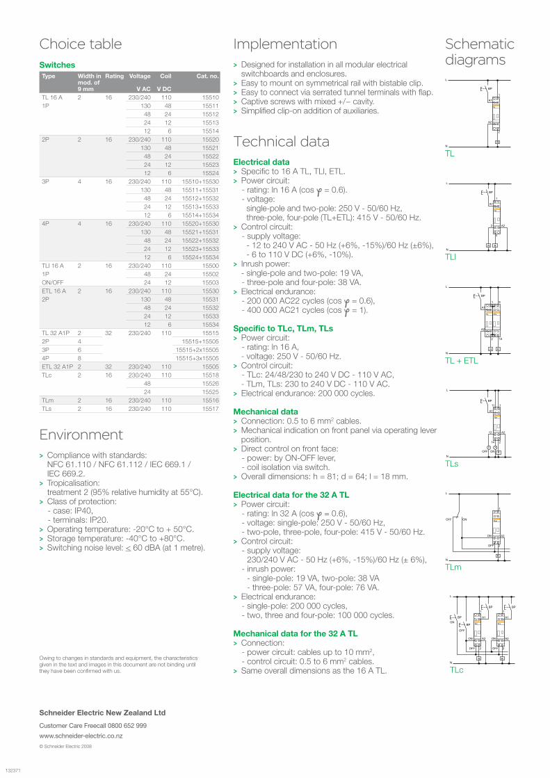
Choice table ImplementationDesigned for installation in all modular electrical >switchboards and enclosures. Easy to mount on symmetrical rail with bistable clip. >Easy to connect via serrated tunnel terminals with flap. >Captive screws with mixed +/− cavity. >Simplified clip-on addition of auxiliaries. >
Technical dataElectrical data
Specific to 16 A TL, TLl, ETL. >Power circuit: >- rating: ln 16 A (cos f = 0.6).- voltage:
single-pole and two-pole: 250 V - 50/60 Hz, three-pole, four-pole (TL+ETL): 415 V - 50/60 Hz.
Control circuit: >- supply voltage: - 12 to 240 V AC - 50 Hz (+6%, -15%)/60 Hz (±6%), - 6 to 110 V DC (+6%, -10%).Inrush power: >
- single-pole and two-pole: 19 VA, - three-pole and four-pole: 38 VA. Electrical endurance: >- 200 000 AC22 cycles (cos f = 0.6), - 400 000 AC21 cycles (cos f = 1).
Specific to TLc, TLm, TLs Power circuit: >- rating: ln 16 A,- voltage: 250 V - 50/60 Hz. Control circuit: >- TLc: 24/48/230 to 240 V DC - 110 V AC,- TLm, TLs: 230 to 240 V DC - 110 V AC.Electrical endurance: 200 000 cycles. >
Mechanical dataConnection: 0.5 to 6 mm > 2 cables.Mechanical indication on front panel via operating lever >position.Direct control on front face: >- power: by ON-OFF lever,- coil isolation via switch. Overall dimensions: h = 81; d = 64; l = 18 mm. >
Electrical data for the 32 A TLPower circuit: >- rating: ln 32 A (cos f = 0.6),- voltage: single-pole: 250 V - 50/60 Hz, - two-pole, three-pole, four-pole: 415 V - 50/60 Hz. Control circuit: >- supply voltage:
230/240 V AC - 50 Hz (+6%, -15%)/60 Hz (± 6%), - inrush power:
- single-pole: 19 VA, two-pole: 38 VA - three-pole: 57 VA, four-pole: 76 VA.
Electrical endurance: >- single-pole: 200 000 cycles, - two, three and four-pole: 100 000 cycles.
Mechanical data for the 32 A TLConnection: >- power circuit: cables up to 10 mm2,- control circuit: 0.5 to 6 mm2 cables. Same overall dimensions as the 16 A TL. >
© Schneider Electric 2008
SwitchesType Width in
mod. of 9 mm
Rating Voltage
V AC
Coil
V DC
Cat. no.
TL 16 A 2 16 230/240 110 155101P 130 48 15511 48 24 15512 24 12 15513 12 6 155142P 2 16 230/240 110 15520 130 48 15521 48 24 15522 24 12 15523 12 6 155243P 4 16 230/240 110 15510+15530 130 48 15511+15531 48 24 15512+15532 24 12 15513+15533 12 6 15514+15534 4P 4 16 230/240 110 15520+15530 130 48 15521+15531 48 24 15522+15532 24 12 15523+15533 12 6 15524+15534 TLI 16 A 2 16 230/240 110 15500 1P 48 24 15502 ON/OFF 24 12 15503 ETL 16 A 2 16 230/240 110 15530 2P 130 48 15531 48 24 15532 24 12 15533 12 6 15534 TL 32 A1P 2 32 230/240 110 15515 2P 4 15515+15505 3P 6 15515+2x15505 4P 8 15515+3x15505 ETL 32 A1P 2 32 230/240 110 15505 TLc 2 16 230/240 110 15518 48 15526 24 15525 TLm 2 16 230/240 110 15516 TLs 2 16 230/240 110 15517
EnvironmentCompliance with standards: >NFC 61.110 / NFC 61.112 / IEC 669.1 / IEC 669.2. Tropicalisation: >treatment 2 (95% relative humidity at 55°C).Class of protection: >- case: IP40, - terminals: IP20. Operating temperature: -20°C to + 50°C. >Storage temperature: -40°C to +80°C. >Switching noise level: > < 60 dBA (at 1 metre).
Owing to changes in standards and equipment, the characteristics given in the text and images in this document are not binding until they have been confirmed with us.
Schematic diagrams


![[ 3000 Series Time Delay Relays and Measuring Relays ... · [ 3000 Series Time Delay Relays and Measuring Relays ] ... Measuring Relays ] • Time Delay Relays ... Dear Reader, Dear](https://img.dokumen.tips/doc/110x75/5b85683b7f8b9aec488e43dd/-3000-series-time-delay-relays-and-measuring-relays-3000-series-time.jpg)