Embed Size (px)
Citation preview

DEV2077.0001Y.107/RAR
DEVON/STATEN ISLAND, LLC
STATEN ISLAND, NEW YORK
Remedial Action Report
NYC BCP Number: 12CBCP032R
Prepared for:
Devon/Staten Island, LLC
2000 Powell Street, Suite 1240
Emeryville, California 94608
Prepared by:
Remedial Engineering, P.C. 209 Shafter Street
Islandia, New York 11749
(631) 232-2600
JUNE 2013

REMEDIAL ENGINEERING, P.C. – i – DEV2077.0001Y.107/RAR
REMEDIAL ACTION REPORT
TABLE OF CONTENTS
LIST OF ACRONYMS ................................................................................................................. iii
CERTIFICATION ...........................................................................................................................v
EXECUTIVE SUMMARY ........................................................................................................... vi
1.0 SITE BACKGROUND .............................................................................................................1 1.1 Site Location and Current Usage ........................................................................................1 1.2 Summary of Site Redevelopment History ..........................................................................1 1.3 Description of Surrounding Property ..................................................................................3 1.4 Remedial Investigation .......................................................................................................3
2.0 DESCRIPTION OF REMEDIAL ACTIONS ..........................................................................6
3.0 COMPLIANCE WITH REMEDIAL ACTION WORK PLAN ...............................................8 3.1 Health and Safety Plan (HASP) ..........................................................................................8 3.2 Community Air Monitoring Plan ........................................................................................8 3.3 Soil/Materials Management Plan ........................................................................................8 3.4 Storm-Water Pollution Prevention ......................................................................................8 3.5 Deviations from the Remedial Action Work Plan ..............................................................8
4.0 REMEDIAL PROGRAM .......................................................................................................10 4.1 Project Organization .........................................................................................................10 4.2 Site Controls......................................................................................................................10 4.3 Materials Excavation and Removal ..................................................................................11 4.4 Materials Disposal ............................................................................................................12 4.5 Backfill Import ..................................................................................................................12
5.0 ENGINEERING CONTROLS ...............................................................................................13
6.0 INSTITUTIONAL CONTROLS ............................................................................................16
7.0 SITE MANAGEMENT PLAN ...............................................................................................17
8.0 SOIL/MATERIALS MANAGEMENT PLAN ......................................................................23 8.1 Soil/Materials Management Plan ......................................................................................23
8.1.1 Soil Screening Methods ...........................................................................................23 8.1.2 Stockpile Methods ...................................................................................................23 8.1.3 Characterization of Excavated Materials .................................................................24 8.1.4 Materials Excavation, Load-Out and Departure ......................................................24 8.1.5 Off-Site Materials Transport ....................................................................................25 8.1.6 Materials Disposal Off Site ......................................................................................25 8.1.7 Import of Backfill Soil from Off-Site Sources ........................................................26 8.1.8 Contingency Plan .....................................................................................................27 8.1.9 Odor, Dust and Nuisance Control ............................................................................30

TABLE OF CONTENTS (Continued)
REMEDIAL ENGINEERING, P.C. – ii – DEV2077.0001Y.107/RAR
FIGURES
1. Site Location Map 2. Site Plan 3. Surrounding Land Usage 4. Site Plan with Composite Cover System
APPENDICES
A. Daily Reports B. Project Photographs C. Disposal Facility Approval Letters D. Disposal Manifest E. Imported Fill Documentation F. Vapor Barrier Product Information G. System Startup Effluent Vapor Analytical Results H. Air Guide-1 Evaluation I Declaration of Covenants and Restrictions J. SSDS Operations and Maintenance Manual
PLATE
1. Sub Slab Depressurization System

REMEDIAL ENGINEERING, P.C. – iii – DEV2077.0001Y.107/RAR
LIST OF ACRONYMS
Acronym Definition
AOC Area of Concern
BLS Below Land Surface
BTEX Benzene, Toluene, Ethylbenzene, Xylenes
CAMP Community Air Monitoring Plan
DER-10 NYSDEC Division of Environmental Remediation Technical Guidance Manual 10
EC Engineering Control
ft2 Square Feet
HASP Health and Safety Plan
IC Institutional Control
NYC VCP New York City Voluntary Cleanup Program
NYC DEP New York City Department of Environmental Protection
NYC DOHMH New York City Department of Health and Mental Hygiene
NYC OER New York City Office of Environmental Remediation
ORC Oxygen Release Compound
PCE Tetrachloroethene
PID Photoionization Detector
PAHs Polycyclic Aromatic Hydrocarbons
QA/QC Quality Assurance/Quality Control
QEP Qualified Environmental Professional
RAR Remedial Action Report
RAWP Remedial Action Work Plan
RI Remedial Investigation
SCG Standards, Criteria and Guidance
SCO Soil Cleanup Objective
SMMP Soil/Materials Management Plan
SMP Site Management Plan
SVOCs Semivolatile Organic Compounds
TCE Trichloroethane
TCLP Toxicity Characteristic Leaching Potential

REMEDIAL ENGINEERING, P.C. – iv – DEV2077.0001Y.107/RAR
Acronym Definition
µg/L Micrograms per Liter
µg/m3 Micrograms per Cubic Meter
UST Underground Storage Tank
VOCs Volatile Organic Compounds


REMEDIAL ENGINEERING, P.C. – vi – DEV2077.0001Y.107/RAR
EXECUTIVE SUMMARY
Site Location and Current Usage
The Site is located at 3131 Richmond Terrace in the Mariners Park section of Staten Island, New
York and is identified as Block 1208 and Lot 10 on the New York City Tax Map. Figure 1 shows
the Site location. The Site is 78,000-square feet and is bounded by May Ship Repair (3075
Richmond Terrace) to the north, Richmond Terrace to the south, May Ship Repair to the east, and
McAllister Towing & Transportation (3165 Richmond Terrace) to the west. A Site Plan is
provided in Figure 2. Currently, the Site is used as a commercial self-storage facility and contains
one 4-story warehouse building connected to one 2-story warehouse building. The buildings are
connected by a common wall and comprise the majority (at least 70%) of the property. Concrete
paved driveways, concrete pads and asphalt parking areas comprise the reminder of the Site. The
building is designed for vehicular access and includes a heating ventilation and air conditioning
(HVAC) system to meet high level air exchange requirements established in NYC building codes
for buildings occupied by motor vehicles. In addition, a grass landscaped area was installed in
front of the building during Site development in 2007 through 2010. All of tax lot 10 and former
tax lot 9 compose the Site. The tax lots were merged into one lot identified as tax lot 10 in 2008.
Summary of Site Redevelopment History
The Site was redeveloped in 2007 – 2010 to construct the Devon Self Storage Facility. Site
redevelopment consisted of renovation of one 2-story building (north building) and demolition of
one pre-existing building (south building) and construction of a new 4-story self-storage
warehouse in its place. In July 1, 2012, Devon Self Storage ceased operations as property
manager for the property and the new property manager, Extra Space, commenced operations on
the Site. Site ownership by Devon/Staten Island LLC has remained consisted throughout the
property manager transfer. The Site is currently zoned as M3-1 for Occupancy Group B-1 –
Moderate Hazard Storage per the New York City Building Code, Title 27, Subchapter 3. Both
Devon’s and Extra Space’s client storage agreement do not allow for the storage of any hazardous
materials on-site. The current and future use of the property as a self-storage warehouse is
consistent with existing zoning for the property. The storage facility is used entirely for
commercial purposes and contains a total floor area of 141,724 square feet (ft2) (sum of 105,480
ft2 new 4-story warehouse and 36,244 ft2 existing 2-story building).

REMEDIAL ENGINEERING, P.C. – vii – DEV2077.0001Y.107/RAR
The warehouse contains an indoor drive through access path for vehicular offloading, multiple
climate controlled storage units, two elevator bays and a 1,200 ft2 office area.
The redevelopment construction work included localized excavation to approximately five (5) feet
below land surface (bls) for pile caps, supports and formwork and less than two (2) feet bls to
build the south building slab. In addition, excavation was performed during the installation of the
drainage system and other small utility installations associated with the building. The existing
concrete slab floor remained intact for the north building and the south building slab was removed,
processed through a crusher, and used as fill at the Site. A Site Summary Report documenting
inspections of the soil handling and disposal was conducted by Professional Services Industries,
Inc. (PSI) during redevelopment and was included with the Remedial Action Work Plan (RAWP).
During redevelopment, a total of 1,212.75 tons of excavated soil was transported to the Middlesex
County Utilities Authority Landfill and used as landfill cover. Soil disposal and characterization
documentation including non-hazardous waste manifests, facility disposal acceptance data, and
soil stockpile analytical data is included in the Site Summary Report. Excavation was timed
during the tidal cycles due to the relatively shallow depth to water (approximately 5 feet bls) and
dewatering was not necessary. No visible signs of petroleum sheen or petroleum impacts were
observed during the excavation. Stockpiled soil sampled for waste profiling indicated low level
concentrations of diesel range organics and heavy metals were present with lead and mercury
detected in excess of the Part 375 Unrestricted Use Soil Cleanup Objectives (SCO) yet at
concentrations below the applicable Part 375 Restricted Commercial SCO. No exceedances of the
Toxicity Characteristic Leachate Procedure (TCLP) metals were detected.
Summary of Environmental Findings
1. The elevation of the Site ranges from 3.8 to 7.5 feet above mean sea level.
2. Depth to groundwater ranges from 3.07 to 4.87 feet bls at the Site.
3. Groundwater flow is generally from the southwest to the northeast beneath the Site.
4. Depth to bedrock is reportedly 40 feet bls based upon driller correspondence, but was not encountered during the investigation at the Site.

REMEDIAL ENGINEERING, P.C. – viii – DEV2077.0001Y.107/RAR
5. The stratigraphy of the Site, from the surface down, consists of an approximately 10 foot thick fine to coarse sand and gravel fill layer underlain by an organic silty clay layer of undetermined thickness.
6. Soil/fill samples collected during the Remedial Investigation (RI) showed no volatile organic compounds (VOCs) that exceeded Track 2 Commercial SCOs in any of the 23 samples collected. Several samples were observed with VOC detections above Track 1 Unrestricted SCOs for benzene, carbon tetrachloride, cis-1,2 dichloroethene, acetone, and trichloroethene. These detections were all well below Track 2 Commercial SCOs. Other VOCs, including some benzene, toluene, ethylbenzene, and xylenes (collectively BTEX) and associated compounds were detected at low and trace levels and well below Track 1 Unrestricted SCOs. A variety of semivolatile organic compounds (SVOCs) were identified above Track 1 and Track 2 Commercial SCOs. All of these exceedances were polycyclic aromatic hydrocarbons (PAH) compounds. Three metals: barium, copper, and lead, exceeded Track 2 Commercial SCOs in soil samples collected at the Site. However, soil samples did not exceed TCLP limits for lead. Several metals exceeded Track 1 Unrestricted SCOs including selenium, zinc, cadmium, arsenic and mercury. In most of these cases Track 1 SCOs were exceeded in only one or two samples. No polychlorinated biphenyls (PCBs) or pesticides exceeded Track 2 Commercial SCOs. PCBs were detected in one sample slightly above the Track 1 Unrestricted SCO. One pesticide, 4,4-DDT was detected in four samples above Track 1 SCOs.
7. Groundwater samples collected during the RI showed no VOCs were detected in groundwater above 6NYCRR Part 703.5 Class GA groundwater quality standards (GQS). Several VOCs were detected in groundwater at trace or low levels but below GQS. Trichloroethane (TCE) and tetrachloroethene (PCE) were not detected in groundwater samples collected during the 2011 sampling event. TCE was found at a trace concentration (1 microgram per liter [µg/L]) in one sample below GQS in the 2007 sampling event. No PCBs or pesticides were detected in groundwater. No SVOCs were detected in groundwater in the 2007 sampling event. Several SVOCs were detected at low concentrations in one sample in the 2011 sampling event. All of the compounds were high molecular weight PAH compounds and may be related to entrained particulates from fill material. Dissolved metals showed no exceedances of GQS with the exception of sodium and manganese. High sodium and manganese suggests the influence of saline intrusion.
8. Soil vapor samples collected during the RI contained a variety of low level findings for BTEX and associated petroleum compounds but generally concentrations were identified below 50 micrograms per cubic meter (µg/m3). PCE was identified in most vapor samples at concentrations as high as 160 µg/m3. TCE was also identified in most samples collected at concentrations as high as 2,100 µg/m3. Chloroform, acetone, and carbon tetrachloride also exceeded 1,000 µg/m3 in one soil vapor sample. These findings generally correlate with VOCs identified in onsite soil samples that exceed Track 1 SCOs and suggest an onsite origin for these vapors. Most of the Site is covered with pavement or concrete building slab and buildup of vapor in the vadose zone below the Site is expected. These findings support the need for vapor mitigation in the remedial action for this property.

REMEDIAL ENGINEERING, P.C. – ix – DEV2077.0001Y.107/RAR
Summary of the Remedy
The following remedial actions were completed in this program:
1. Prepared a Community Protection Statement and implemented a Citizen Participation Plan. A fact sheet announcing start of remedial construction was issued on August 27, 2012.
2. Performed a Community Air Monitoring Program for particulates and volatile organic carbon compounds. Excavated soil/fill material was screened during intrusive work for indications of contamination by visual means, odor, and monitoring with a photo ionization detector (PID).
3. Site mobilization involving Site security setup, equipment mobilization, and marking & staking of proposed SSDS extraction points. A pre-construction meeting with all project personnel was conducted on February 6, 2013.
4. Performed all activities required for the remedial action, including permitting requirements and pretreatment requirements, in compliance with applicable laws and regulations.
5. Established Track 4 Soil Cleanup Objectives (SCOs).
6. Excavated two suction pits, each pit 2-feet wide by 2-feet long by 18-inches deep.
7. Obtained post-excavation end point samples for chemical analysis.
8. Completed an engineered composite cover consisting of concrete and asphalt pavement and building slab to prevent human exposure to residual soil/fill remaining under the Site.
9. Replaced damaged vapor barrier in the suction pit areas by new vapor barrier manufactured by W. R. Meadows.
10. Installed an active sub-slab depressurization system (SSDS). This new SSDS was tested for operations on March 1, 2013.
11. Imported washed gravel materials from Tilcon, NY Inc. This gravel was used as backfill material in compliance with the RAWP and in accordance with applicable laws and regulations.
12. Transported 1,212.75 tons of excavated soil to the Middlesex County Utilities Authority Landfill and used as landfill cover for off Site in accordance with applicable laws and regulations for handling, transport, and disposal, and the RAWP. Sampling and analysis of excavated media was performed as required by disposal facilities.
13. Submitted a RAR that describes the remedial activities, certifies that the remedial requirements have been achieved, defines the Site boundaries, describes all Engineering and Institutional Controls to be implemented at the Site, and lists any changes from the RAWP.

REMEDIAL ENGINEERING, P.C. – x – DEV2077.0001Y.107/RAR
14. Submitted an OER approved Site Management Plan (SMP) in the RAR for long-term management of residual historic fill contamination, including plans for operation, maintenance, monitoring, inspection and certification of Engineering and Institutional Controls and reporting at a specified frequency.
15. Recorded a Declaration of Covenants and Restrictions that includes a listing of Engineering Controls and a requirement that management of these controls must be in compliance with an approved SMP; and Institutional Controls including prohibition of the following: (1) vegetable gardening and farming; (2) use of groundwater without treatment rendering it safe for the intended use; (3) disturbance of residual contaminated material unless it is conducted in accordance with the SMP; and (4) higher level of land usage without OER-approval.

REMEDIAL ENGINEERING, P.C. – 1 – DEV2077.0001Y.107/RAR
1.0 SITE BACKGROUND
Devon/Staten Island, LLC (Devon) has enrolled in the New York City Voluntary Cleanup
Program (NYC VCP) to investigate and remediate a property located at 3131 Richmond Terrace in
the Mariners Park section of Staten Island, New York. A Remedial Investigation (RI) was
performed to compile and evaluate data and information necessary to develop a Remedial Action
Work Plan (RAWP). A remedial action was performed pursuant to an OER-approved RAWP in a
manner that has rendered the Site protective of public health and the environment consistent with
the proposed use of the property. This Remedial Action Report (RAR) describes the remedial
action performed under the RAWP. The remedial action described in this document provides for
the protection of public health and the environment, complies with applicable environmental
standards, criteria and guidance and applicable laws and regulations.
1.1 Site Location and Current Usage
The Site is located at 3131 Richmond Terrace in the Mariners Park section of Staten Island, New
York and is identified as Block 1208 and Lot 10 on the New York City Tax Map. Figure 1 shows
the Site location. The Site is 78,000-square feet and is bounded by May Ship Repair (3075
Richmond Terrace) to the north, Richmond Terrace to the south, May Ship Repair to the east, and
McAllister Towing & Transportation (3165 Richmond Terrace) to the west. A Site Plan is
provided in Figure 2. Currently, the Site is used as a commercial self-storage facility and contains
one 4-story warehouse connected to one 2-story warehouse building. The buildings are connected
by a common wall and comprise the majority (at least 70%) of the property. Concrete paved
driveways, concrete pads and asphalt parking areas comprise the reminder of the Site. The
building is designed for vehicular access and includes a heating ventilation and air conditioning
(HVAC) system to meet high level air exchange requirements established in NYC building codes
for buildings occupied by motor vehicles. In addition, a grass landscaped area was installed in
front of the building during Site development in 2007 through 2010. All of tax lot 10 and former
tax lot 9 compose the Site. The tax lots were merged into one lot identified as tax lot 10 in 2008.
1.2 Summary of Site Redevelopment History
The Site was redeveloped from 2007 through 2010 to construct the Devon Self Storage Facility.
Site redevelopment consisted of renovation of one 2-story building (north building) and
demolition of one pre-existing building (south building) and construction of a new 4-story self-

REMEDIAL ENGINEERING, P.C. – 2 – DEV2077.0001Y.107/RAR
storage warehouse in its place. In July 1, 2012, Devon Self Storage ceased operations as property
manager for the property and the new property manager, Extra Space, commenced operations on
the Site. Site ownership by Devon/Staten Island LLC has remained consisted throughout the
property manager transfer. The Site is currently zoned as M3-1 for Occupancy Group B-1 –
Moderate Hazard Storage per the New York City Building Code, Title 27, Subchapter 3. Both
Devon’s and Extra Space’s client storage agreement do not allow for the storage of any hazardous
materials on-site. The current and future use of the property as a self-storage warehouse is
consistent with existing zoning for the property. The storage facility is used entirely for
commercial purposes and contains a total floor area of 141,724 square feet (ft2) (sum of 105,480
ft2 new 4-story warehouse and 36,244 ft2 existing 2-story building).
The warehouse contains an indoor drive through access path for vehicular offloading, multiple
climate controlled storage units, two elevator bays and a 1,200 ft2 office area.
The redevelopment construction work included localized excavation to approximately five (5) feet
below land surface (bls) for pile caps, supports and formwork and less than two (2) feet bls to
build the south building slab. In addition, excavation was performed during the installation of the
drainage system and other small utility installations associated with the building. The existing
concrete slab floor remained intact for the north building and the south building slab was removed,
processed through a crusher, and used as fill at the Site. A Site Summary Report documenting
inspections of the soil handling and disposal was conducted by Professional Services Industries,
Inc. (PSI) during redevelopment and was included in the RAWP.
During redevelopment, a total of 1,212.75 tons of excavated soil was transported to the Middlesex
County Utilities Authority Landfill and used as landfill cover. Soil disposal and characterization
documentation including non-hazardous waste manifests, facility disposal acceptance data, and
soil stockpile analytical data is including in the Site Summary Report. Excavation was timed
during the tidal cycles due to the relatively shallow depth to water (approximately 5 feet bls) and
dewatering was not necessary. No visible signs of petroleum sheen or petroleum impacts were
observed during the excavation. Stockpiled soil sampled for waste profiling indicated low level
concentrations of diesel range organics and heavy metals were present with lead and mercury
detected in excess of the Part 375 Unrestricted Use Soil Cleanup Objectives (SCOs) yet at

REMEDIAL ENGINEERING, P.C. – 3 – DEV2077.0001Y.107/RAR
concentrations below the applicable Part 375 Restricted Commercial SCOs. No exceedances of
the Toxicity Characteristic Leachate Procedure (TCLP) metals were detected.
1.3 Description of Surrounding Property
The Site is located in a mixed use area with industrial, residential, and commercial neighbors
bordering the Site. Historically, ship building and maintenance were performed on the Site and on
the surrounding properties to the north, west and east. Currently, residential housing is located
across the street on the south side of Richmond Terrace. Industrial and commercial land uses
border the property on all three sides north of Richmond Terrace. McAllister Towing &
Transportation, a maritime barge and tugboat company, is located directly to the west of the Site.
Richmond Industrial composes several lots located to the north and east of the Site. North and
east of the Richmond Industrial property is the Kill Van Kull/Newark Bay that separates Staten
Island from New Jersey. A pier extending into Newark Bay is approximately 100 feet east of the
Site. Directly east of the Site is a building owned by JT&JG realty that is leased to a commercial
coffee roasting business, Unique Coffee Roasters.
Sensitive receptors include the downgradient Newark Bay and upgradient residential properties
located south of Richmond Terrace. No known schools, hospitals or day care centers are within
500 feet of the Site. A day care center, Fellowship Learning Center, is located approximately 700
feet upgradient of the Site on the southeast corner of Richmond Terrace and Lockman Avenue
(3036 Richmond Terrace).
Figure 3 shows the surrounding land usage.
1.4 Remedial Investigation
A remedial investigation was performed and the results are documented in a companion document
called “Remedial Investigation Report, Devon/Staten Island LLC,” dated March 2012 (RIR).
Summary of Past Uses of Site and Areas of Concern
Past Site uses included historic ship building and maintenance operations from owners including
Staten Island Shipbuilding Co., United Shipyards, Inc., and Bethlehem Steel. These owners were
listed in Sanborn maps dating from 1917 through 1962. Following the 1960’s various users

REMEDIAL ENGINEERING, P.C. – 4 – DEV2077.0001Y.107/RAR
occupied the premises and prior to site redevelopment in 2007, the property was used for chair
manufacturing (e.g., injection foam molding, metal fabrication, and chair assembly).
Past usage of the property and the likely presence of historic fill constitute the Areas of Concern
(AOC) for this property.
Summary of the Work Performed under the Remedial Investigation
Devon/Staten Island LLC performed the following scope of work:
1. Conducted a Site inspection to identify AOCs and physical obstructions (i.e., structures, buildings, etc.);
2. Installed eight soil borings across the entire project Site, and collected nine soil samples for chemical analysis from the soil borings to evaluate soil quality;
3. Installed four groundwater monitoring wells throughout the Site to establish groundwater flow and collected five groundwater samples for chemical analysis to evaluate groundwater quality;
4. Installed six soil vapor probes around Site perimeter and collected six soil vapor samples and one indoor air sample for chemical analysis.
Summary of Environmental Findings
1. Elevation of the property ranges from 3.8 to 7.5 feet above mean seal level.
2. Depth to groundwater ranges from 3.07 to 4.87 feet bls at the Site.
3. Groundwater flow is generally from the southwest to the northeast beneath the Site towards Newark Bay.
4. Depth to bedrock is reportedly 40 feet bls based upon driller correspondence, but was not encountered during the investigation at the Site.
5. The stratigraphy of the Site, from the surface down, consists of an approximately 10 foot thick fine to coarse sand and gravel fill layer underlain by an organic silty clay layer of undetermined thickness.
6. Soil/fill samples collected during the RI showed no VOCs that exceeded Track 2 Commercial SCOs in any of the 23 samples collected. Several samples were observed with VOC detections above Track 1 Unrestricted SCOs for benzene, carbon tetrachloride, cis-1,2 dichloroethene, acetone and trichloroethene. These detections were all well below Track 2 Commercial SCOs. Other VOCs including some petroleum (i.e., benzene, toluene, ethylbenzene, and xylenes (collectively BTEX) associated compounds were detected at low and trace levels and well below Track 1 Unrestricted SCOs. A variety of

REMEDIAL ENGINEERING, P.C. – 5 – DEV2077.0001Y.107/RAR
SVOCs were identified above Track 1 and Track 2 Commercial SCOs. All of these exceedances were PAH compounds. Three metals: barium, copper and lead, exceeded Track 2 Commercial SCOs in soil samples collected at the Site. However, soil samples did not exceed TCLP limits for lead. Several metals exceeded Track 1 Unrestricted SCOs including selenium, zinc, cadmium, arsenic and mercury. In most of these cases Track 1 SCOs were exceeded in only one or two samples. No PCBs or pesticides exceeded Track 2 Commercial SCOs. PCBs were detected in one sample slightly above the Track 1 Unrestricted SCO. One pesticide, 4,4-DDT was detected in four samples above Track 1 SCOs.
7. Groundwater samples collected during the RI showed no VOCs were detected in groundwater above 6NYCRR Part 703.5 Class GA GQS. Several VOCs were detected in groundwater at trace or low levels but below GQS. TCE and PCE were not detected in groundwater samples collected during the 2011 sampling event. TCE was found at a trace concentration (1µg/L) in one sample below GQS in the 2007 sampling event. No PCBs or pesticides were detected in groundwater. No SVOCs were detected in groundwater in the 2007 sampling event. Several SVOCs were detected at low concentrations in one sample in the 2011 sampling event. All of the compounds were high molecular weight PAH compounds and may be related to entrained particulates from fill material. Dissolved metals showed no exceedance of GQS with the exception of sodium and manganese. High sodium suggests the influence of saline intrusion.
8. Soil vapor samples collected during the RI contained a variety of low level findings for BTEX and associated petroleum compounds but generally concentrations were identified below 50 µg/m3. PCE was identified in most vapor samples at concentrations as high as 160 µg/m3. TCE was also identified in most samples collected and had a high concentration of 2,100 µg/m3. Chloroform, acetone and carbon tetrachloride also exceeded 1,000 µg/m3 in at least one soil vapor sample. These findings generally correlate with VOCs identified in onsite soil samples that exceed Track 1 SCOs and suggest an onsite origin for these vapors. Most of the Site is covered with pavement or concrete building slab and buildup of vapor in the vadose zone below the Site is expected. These findings support the need for vapor mitigation in the remedial action for this property.
For more detailed results, consult the RIR. Based on an evaluation of the data and information
presented in the RIR and the RAWP, disposal of significant amounts of hazardous waste is not
suspected at this Site.

REMEDIAL ENGINEERING, P.C. – 6 – DEV2077.0001Y.107/RAR
2.0 DESCRIPTION OF REMEDIAL ACTIONS
The factors considered during the selection of the remedial action included protection of human
health, protection of the environment, compliance with standards, criteria, and guidelines (SCGs),
short-term effectiveness and impacts, long-term effectiveness and permanence, reduction of
toxicity, mobility, or volume of contaminated material, implementability, cost effectiveness,
community acceptance, land use, and sustainability of the remedial action. The Site was
remediated in accordance with the scope of work presented in an OER-approved RAWP dated
March 2012 and the stipulations as noted in a July 18, 2012 Stipulation Letter. All deviations
from the RAWP are noted below.
The following remedial actions were completed in this program:
1. Prepared a Community Protection Statement and implemented a Citizen Participation Plan. A fact sheet announcing start of remedial construction was issued on August 27, 2012.
2. Performed a Community Air Monitoring Program for particulates and volatile organic carbon compounds. Excavated soil/fill material was screened during intrusive work for indications of contamination by visual means, odor, and monitoring with a photo ionization detector (PID).
3. Site mobilization involving Site security setup, equipment mobilization, and marking & staking of proposed SSDS extraction points. A pre-construction meeting with all project personnel was conducted on February 6, 2013.
4. Performed all activities required for the remedial action, including permitting requirements and pretreatment requirements, in compliance with applicable laws and regulations.
5. Established Track 4 Soil Cleanup Objectives (SCOs).
6. Excavated two suction pits, each pit 2 feet wide by 2 feet long by 18 inches deep.
7. Obtained post-excavation end point samples for chemical analysis.
8. Completed an engineered composite cover consisting of concrete and asphalt pavement and building slab to prevent human exposure to residual soil/fill remaining under the Site.
9. Replaced damaged vapor barrier in the suction pit areas by new vapor barrier manufactured by W. R. Meadows.
10. Installed an active sub-slab depressurization system (SSDS). This new SSDS was tested for operations on March 1, 2013.

REMEDIAL ENGINEERING, P.C. – 7 – DEV2077.0001Y.107/RAR
11. Imported washed gravel materials from Tilcon, NY Inc. This gravel was used as backfill material in compliance with the RAWP and in accordance with applicable laws and regulations.
12. Transported 1,212.75 tons of excavated soil to the Middlesex County Utilities Authority Landfill and used as landfill cover for off Site in accordance with applicable laws and regulations for handling, transport, and disposal, and the RAWP. Sampling and analysis of excavated media was performed as required by disposal facilities.
13. Submitted a RAR that describes the remedial activities, certifies that the remedial requirements have been achieved, defines the Site boundaries, describes all Engineering and Institutional Controls to be implemented at the Site, and lists any changes from the RAWP.
14. Submitted an OER approved Site Management Plan (SMP) in the RAR for long-term management of residual historic fill contamination, including plans for operation, maintenance, monitoring, inspection and certification of Engineering and Institutional Controls and reporting at a specified frequency.
15. Recorded a Declaration of Covenants and Restrictions that includes a listing of Engineering Controls and a requirement that management of these controls must be in compliance with an approved SMP; and Institutional Controls including prohibition of the following: (1) vegetable gardening and farming; (2) use of groundwater without treatment rendering it safe for the intended use; (3) disturbance of residual contaminated material unless it is conducted in accordance with the SMP; and (4) higher level of land usage without OER-approval.

REMEDIAL ENGINEERING, P.C. – 8 – DEV2077.0001Y.107/RAR
3.0 COMPLIANCE WITH REMEDIAL ACTION WORK PLAN
3.1 Health and Safety Plan (HASP)
The remedial construction activities performed under this program were in compliance with the
Health and Safety Plan and applicable laws and regulations. The Site Safety Coordinator was
Christina Prete.
3.2 Community Air Monitoring Plan
Intrusive work performed under this program was limited to two small excavations for the
installation of suction pits associated with the SSDS. Both suction pits are located in the floor of
the office space of the south building. Since both excavations were located indoors, community
air monitoring at the site perimeter was not required by OER. Localized screening of the
excavated soils with a photoionization detector was performed.
3.3 Soil/Materials Management Plan
The Soil/Materials Management Plan (SMMP) in the RAWP provided detailed plans for
managing all soils/materials that were disturbed at the Site, including excavation, handling,
storage, transport, and disposal. It also included a series of controls to assure effective, nuisance
free remedial activity in compliance with applicable laws and regulations. Remedial construction
activities performed under this program were in full compliance with the SMMP in the approved
RAWP.
3.4 Storm-Water Pollution Prevention
Intrusive work performed under this program was limited to two small excavations for the
installation of suction pits associated with the SSDS. Both suction pits are located in the floor of
the office space of the south building. Since both excavations were located indoors, storm water
pollution prevention was not required by OER.
3.5 Deviations from the Remedial Action Work Plan
Intrusive work performed under this program was limited to two small excavations for the
installation of suction pits associated with the SSDS. Both suction pits are located in the floor of
the office space of the south building. Since both excavations were located indoors, community

REMEDIAL ENGINEERING, P.C. – 9 – DEV2077.0001Y.107/RAR
air monitoring at the site perimeter was not required by OER. Localized screening of the
excavated soils with a photoionization detector was performed.
The location of one SSDS suction pit, SP-1, was modified, with prior OER consent, approximately
3 feet from the main vestibule client entry space to the office space directly beyond the main
vestibule client entry space’s rear wall. SP-1 was relocated approximately 3 feet on the other side
of this wall to avoid damaging granite floor tile and prevent vertical suction piping installation in
the main vestibule client entry space. This suction pit relocation had no effect on the system’s
functionality as evidenced by the startup testing results.

REMEDIAL ENGINEERING, P.C. – 10 – DEV2077.0001Y.107/RAR
4.0 REMEDIAL PROGRAM
4.1 Project Organization
Principal personnel who participated in the remedial action include Joshua B. Levine, Principal
Engineer and Christina Prete, Staff Engineer. The Professional Engineer (PE) for this project is
Joshua Levine. The Remedial Contractor that installed the SSDS was Metro Environmental
Contracting Corp. of Lindenhurst, New York.
4.2 Site Controls
Site Preparation
Mobilization was conducted as necessary for each phase of work at the Site. Mobilization
included field personnel orientation, equipment mobilization (including securing all sampling
equipment needed for the field investigation), marking/staking sampling locations and utility
mark-outs. Each field team member attended an orientation meeting to become familiar with the
general operation of the Site, health and safety requirements, and field procedures.
A pre-construction meeting was held with all contractors on February 6, 2013. An OER Project
Notice was erected at the project entrance and in place during all phases of the Remedial Action.
Utility Marker Layouts, Easement Layouts
Proper safety and protective measures pertaining to utilities and easements, and compliance with
all laws and regulations were employed during invasive and other work completed under the
RAWP. The integrity and safety of on-Site and off-Site structures was maintained during all
invasive work including excavation.
Equipment and Material Staging
Equipment and materials were stored and staged in a manner that complies with applicable laws
and regulations.
Soil Screening
Excavated soils associated with the installation of the two suction pits were screened for impacts
using visual, olfactory and PID observations. Impacted soils were not observed and no PID
detections were identified during excavation soil screening.

REMEDIAL ENGINEERING, P.C. – 11 – DEV2077.0001Y.107/RAR
Stockpile Management
In order to prevent stockpiling, excavated soils were transferred directly to 55-gallon drums
located on poly-sheeting next to the excavation. No soil stockpiles were generated during the
Remedial Action.
Site Security
Site access was controlled by Devon/Staten Island, LLC through keypad access to the storage
facility. All construction activities were performed inside the building. The work areas were
delineated and access was restricted with barrier tape and cones.
Reporting
Daily reports providing a general summary of activities for each day of intrusive remedial work
were emailed to the OER Project Manager by the end of the following day. Those reports
included:
Project number and statement of the activities and an update of progress made and locations of work performed;
Quantities of material imported and exported from the Site;
Status of on-Site soil/fill stockpiles;
A summary of all citizen complaints, with relevant details (basis of complaint; actions taken; etc.), if any;
Photographs of notable Site conditions and activities.
Daily reports are included as Appendix A. Digital photographs of the remedial action are included
in Appendix B.
4.3 Materials Excavation and Removal
Construction of suction pits one and two associated with the SSDS were performed on February 6
and 7, 2013. Construction of the suction pits entailed removing the concrete slab and excavating
each pit 2-feet wide by 2-feet long by 18-inches deep. The excavated soils were directly
transferred to 55-gallon drums and temporarily stored onsite pending offsite transportation for
proper disposal. In total, four 55-gallon drums of nonhazardous waste soil were generated during
construction of the suction pits.

REMEDIAL ENGINEERING, P.C. – 12 – DEV2077.0001Y.107/RAR
A map showing the location where excavations were performed is shown in Plate 1.
End Point Sample Results
No end point samples were collected.
4.4 Materials Disposal
A composite sample was collected from the excavated soils associated with the suction pits for
waste characterization purposes. Analytical results indicated that the soils can be classified as
non-hazardous.
The tonnage and destination of material removed and disposed off Site is presented below:
Destination Type of Material Quantity
Republic Environmental Systems (PA), Inc. Nonhazardous Soil 4 Drums (1.5 tons estimated)
Letters from Roux Associates to the disposal facility providing materials type, source and data,
and acceptance letters from disposal facility stating it is approved to accept above materials are
attached in Appendix C. The drum disposal waste manifest is included in Appendix D. The table
above shows the total quantities of each class of material removed from the Site and the disposal
locations.
4.5 Backfill Import
The two suction pits were both backfilled with washed gravel supplied by Tilcon, NY Inc.
(Tilcon) from their West Nyack facility. Tilcon provided a letter that certified the material was
100% virgin Traprock (Diabase) that is quarried and processed to finished sizes and is clean and
free from contamination.
A copy of the Tilcon certification letter is included in Appendix E. A map showing backfill
placement locations at the Site is shown on Plate 1.

REMEDIAL ENGINEERING, P.C. – 13 – DEV2077.0001Y.107/RAR
5.0 ENGINEERING CONTROLS
Engineering Controls were employed in the remedial action to address residual contamination
remaining at the Site. The Site has three primary Engineering Control Systems. These are:
(1) composite cover system consisting of asphalt covered roads, concrete covered sidewalks, and concrete building slabs;
(2) soil vapor barrier; and
(3) sub-slab depressurization system (SSDS).
Composite Cover System
Exposure to residual soil/fill is prevented by the existing composite cover system on Site. This
composite cover system is comprised of:
asphalt covered roads/parking;
concrete covered sidewalks/driveway; and
concrete building slabs.
Figure 4 shows the location of each cover type built at the Site.
The composite cover system is a permanent engineering control for the Site. The system will be
inspected and reported at specified intervals as required by the RAWP and the SMP. A Soil
Management Plan will be included in the Site Management Plan and will outline the procedures to
be followed in the event that the composite cover system and underlying residual soil/fill is
disturbed after the remedial action is complete. Maintenance of this composite cover system is
described in the Site Management Plan in (Section 7.0).
Vapor Barrier
Migration of soil vapor is accomplished with a combination of building slab and vapor barrier.
A vapor barrier was installed during construction of the south warehouse building in 2007.
Construction details depicting the vapor barrier were not provided in the development design
drawings, but the vapor barrier was confirmed in 2011 by Roux Associates during the RI and in
March 6 and 7, 2013 during installation of the SSDS suction pits. The existing yellow vapor
barrier with red tape shown in the photos provided in Appendix B is consistent with Stego Wrap, a
standard vapor barrier that comes in 10 mil and 15 mil thicknesses.

REMEDIAL ENGINEERING, P.C. – 14 – DEV2077.0001Y.107/RAR
A new 10-mil vapor barrier, Perminator by W.R. Meadows, was placed overlapping the existing
vapor barrier and taped prior to restoration of the concrete slab in each suction pit. The product
specification for the new vapor barrier is provided in Appendix F.
Sub-slab Depressurization System
Migration of soil vapor is mitigated with the construction of an active SSDS. The purpose of the
SSDS is to mitigate the elevated concentrations of contamination within the soil gas beneath the
building and minimize exposure risk to the workers within the building.
The following describes the layout details of the SSDS:
The SSDS is comprised of two suction pits (SP-1 and SP-2) spaced approximately 20 feet apart and located under the office space, which is the only occupied area in the building (Plate 1).
The suction pits are 2-feet by 2-feet by 18-inches deep gravel pits installed just below the concrete slab as detailed in Plate 1.
A 4-inch diameter Schedule 80 polyvinyl chloride (PVC) pipe was installed within the gravel suction pit terminating with a tee connected to slotted PVC screen (Plate 1).
Each suction pit’s extraction pipe runs vertically from the suction pit slab penetration to the first floor ceiling where the individual vertical pipes are manifolded together to a common horizontal header pipe mounted to the ceiling’s structural steel support system. The common horizontal header pipe penetrates the warehouse building exterior sidewall and runs to the SSDS equipment area shown in Plate 1.
A vapor extraction blower equipped with a control panel, vacuum gauge, flow meter, vapor sampling port and effluent discharge stack was installed in the SSDS equipment area.
On March 1, 2013, System testing and effluent air monitoring was performed at SSDS startup to
confirm operation. Vacuum and flow levels were recorded and an effluent air sample was
collected and analyzed for TO-15 list VOCs.
Flow readings were collected at both the influent and effluent side of the blower (indicated by
pressure and vacuum gauges) and ranged from 90- 95cubic feet per minute (cfm) corresponding to
an influent and effluent discharge pressure of 5 inches of water column.

REMEDIAL ENGINEERING, P.C. – 15 – DEV2077.0001Y.107/RAR
Vacuum measurements were taken at soil vapor monitoring points SV-1 and SV-2, which are
located 10 feet and 60 feet away from suction pit SP-2 respectively. Vacuum readings were
0.108 inches of water at SV-1 and 0.073 inches of water at SV-2.

REMEDIAL ENGINEERING, P.C. – 16 – DEV2077.0001Y.107/RAR
6.0 INSTITUTIONAL CONTROLS
A series of Institutional Controls are required under this Remedial Action to implement, maintain
and monitor Engineering Controls and prevent future exposure to residual contamination by
controlling disturbances of the subsurface soil. Adherence to these Institutional Controls is
required under the Declaration of Covenants and Restrictions recorded with the deed for this
property and will be implemented under the Site Management Plan included in this RAR. These
Institutional Controls for the Site are:
(1) Recording of an OER-approved Declaration of Covenant and Restrictions (DCR) with the City Register or county clerk as appropriate. The DRAFT DCR is included as Appendix J. DCR includes a description of all ECs and ICs, including items (2) through (6) below, summarizes the requirements of the Site Management Plan, and will note that the property owner and property owner’s successors and assigns must comply with the approved SMP;
(2) Submittal of a Site Management Plan in this RAR that provides procedures for appropriate operation, maintenance, monitoring, inspection, reporting, and certification of ECs. The SMP is included as Section 7.0, requires that the property owner and property owner’s successors and assigns will submit to OER a periodic written statement that certifies that: (1) controls employed at the Site are unchanged from the previous certification or that any changes to the controls were approved by OER; and, (2) nothing has occurred that impairs the ability of the controls to protect public health and environment or that constitute a violation or failure to comply with the SMP. OER retains the right to enter the Site in order to evaluate the continued maintenance of any controls. This certification shall be submitted annually and will comply with RCNY §43-1407(l)(3).
(3) Vegetable gardens and farming on the Site are prohibited;
(4) Use of groundwater underlying the Site is prohibited without treatment rendering it safe for its intended use;
(5) All future activities on the Site that will disturb residual material must be conducted pursuant to the soil management provisions in an approved SMP;
(6) The Site will be used for commercial use and will not be used for a higher level of use without prior approval by OER.

REMEDIAL ENGINEERING, P.C. – 17 – DEV2077.0001Y.107/RAR
7.0 SITE MANAGEMENT PLAN
Site management is the last phase of the remedial process and begins after the approval of the
Remedial Action Report (RAR) and issuance of the Notice of Completion (NOC) by OER. It is
the responsibility of the property owner to ensure that all Site management responsibilities are
performed. The penalty for failure to implement the SMP includes revocation of the Notice of
Completion and all associated certifications and liability protections.
Engineering Controls (ECs) and Institutional Controls (ICs) have been incorporated into this
remediation to ensure that the Site remains protective of public health and the environment. EC’s
provide physical protective measures. ICs provide restrictions on Site usage and provide
operation, maintenance, monitoring and reporting measures. A Site-specific Declaration of
Covenants and Restrictions has been recorded to memorialize these ECs and ICs. This SMP
includes all methods necessary to ensure compliance with ECs and ICs required for the property.
The SMP provides a detailed description of procedures required to manage residual material at the
Site following the completion of remedial construction in accordance with the NYC Brownfield
Cleanup Agreement with OER. This includes: (1) implementation of Engineering and
Institutional Controls; (2) operation and maintenance of Engineering Controls (3) periodic
inspections and (4) certification of Engineering Controls and Institutional Controls.
Site inspection and EC/IC certification will be performed in the third year and every third year
thereafter.
ENGINEERING AND INSTITUTIONAL CONTROLS
Engineering Controls
Engineering Controls are employed in the remedial action to address residual materials remaining
at the site. The Site has three Engineering Controls. These are:
composite cover system consisting of asphalt covered roads, concrete covered sidewalks, and concrete building slabs;
soil vapor barrier; and
sub-slab depressurization system.

REMEDIAL ENGINEERING, P.C. – 18 – DEV2077.0001Y.107/RAR
Composite Cover System
The composite cover system is a permanent engineering control for the Site. The system will be
inspected and its performance certified at specified intervals defined in this SMP. A
Soil/Materials Management Plan is included in this Site Management Plan to outline the
procedures to be followed in the event that the composite cover system and underlying residual
soil/material must be disturbed after the remedial action is complete.
Vapor Barrier
Migration of soil vapor is mitigated with a combination of building slab and vapor barrier. The
vapor barrier is a permanent engineering control for the Site underlying the concrete slab. The
concrete slab will be inspected at specific intervals defined in this SMP. Any visible damage to
the concrete slab that could indicate damage to the underlying vapor barrier will be inspected at
specific intervals as required by this SMP.
Sub-Slab Depressurization System (SSDS)
Migration of soil vapor is mitigated with the construction of an active sub-slab depressurization
system. Sub-slab depressurization is a permanent engineering control for the site. The system
will be inspected and its performance certified at specific intervals as required by this SMP.
The SSDS will be operated and maintained as prescribed below.
System Operation: Routine Operation Procedures
When properly piped, fitted and applied, little maintenance is required. The blower is equipped
with sealed bearings that require no maintenance.
The moisture separator has been designed to require minimal maintenance. During normal
operation a layer of sludge may build up on the bottom of the separator. As necessary, the top
assembly of the separator should be removed and the inside cleaned out with water. Keeping the
inside clean will prevent the valve from being clogged with sediment. The relief valve should be
inspected upon emptying the separator and readjusted upon restart.
Manufacturers’ specifications, recommendations, troubleshooting guides, and operation and maintenance schedules are included in Appendix I.

REMEDIAL ENGINEERING, P.C. – 19 – DEV2077.0001Y.107/RAR
Institutional Controls
A series of Institutional Controls are employed in the remedial action of this property.
Institutional Controls are intended to: 1) operate, maintain, inspect and certify Engineering
Controls and Institutional Controls; 2) prevent future exposure to residual soil/materials by
controlling disturbances in the subsurface; and, 3) restrict higher uses of the property than those
addressed by the remedy. The following Institutional Controls apply to this property:
(1) Recording of an OER-approved Declaration of Covenant and Restrictions (DCR) with the City Register or county clerk as appropriate. The DCR is included as Appendix J. DCR includes a description of all ECs and ICs, including items (2) through (6) below, summarizes the requirements of the Site Management Plan, and will note that the property owner and property owner’s successors and assigns must comply with the approved SMP;
(2) Submittal of a Site Management Plan that provides procedures for appropriate operation, maintenance, monitoring, inspection, reporting, and certification of ECs. The SMP requires that the property owner and property owner’s successors and assigns will submit to OER a periodic written statement that certifies that: (1) controls employed at the Site are unchanged from the previous certification or that any changes to the controls were approved by OER; and, (2) nothing has occurred that impairs the ability of the controls to protect public health and environment or that constitute a violation or failure to comply with the SMP. OER retains the right to enter the Site in order to evaluate the continued maintenance of any controls. This certification shall be submitted at the end of the third years and every three years thereafter.
(3) Vegetable gardens and farming on the Site are prohibited;
(4) Use of groundwater underlying the Site is prohibited without treatment rendering it safe for its intended use;
(5) All future activities on the Site that will disturb residual material must be conducted pursuant to the soil management provisions in an approved SMP;
(6) The Site will be used for commercial use and will not be used for a higher level of use without prior approval by OER.
Engineering Controls and Institutional Controls will be inspected and their performance certified
at a frequency and in a manner defined in this SMP. A Declaration of Covenants and Restrictions
or Environmental Designation has been recorded that provides notice of obligations for site
management.

REMEDIAL ENGINEERING, P.C. – 20 – DEV2077.0001Y.107/RAR
INSPECTIONS
Inspection of IC/EC’s will be conducted in the third year and every three years thereafter. The
inspections will evaluate the following:
Whether Engineering Controls continue to perform as designed;
If these controls continue to be protective of human health and the environment;
If compliance with this SMP has been maintained;
If remedial performance criteria continues to be achieved;
If site records are complete and up to date; and
Whether changes are needed to the remedial systems;
If compliance with institutional controls has been maintained; and
General Site conditions at the time of inspection.
If an emergency, such as a natural disaster or an unforeseen failure of any of the engineering
controls occurs, an inspection of the Site will be conducted by a qualified environmental
professional.
Engineering Control Inspection
The engineering control inspections will include the following:
Composite Cover
– The composite cover will be inspected to confirm that interior concrete building slabs and exterior concrete and asphalt parking and driveways are continuous and do not show signs of removal/replacement.
Vapor Barrier
– The Vapor barrier underlying the interior concrete slab is inaccessible since it is beneath the slab. Therefore, an inspection of the interior building concrete slab will be performed to check for cracking or patchwork that could indicate damage to the slab. Any new signs of disturbance to the slab and potential damage to the underlying vapor barrier will be identified in the inspection.
SSDS
– The SSDS will be inspected for system operation. Items to be noted during inspection include:
♦ Condition of interior and exterior piping;

REMEDIAL ENGINEERING, P.C. – 21 – DEV2077.0001Y.107/RAR
♦ Condition of floor in vicinity of suction pits 1 and 2;
♦ Water levels in moisture separator (drain as necessary);
♦ Dilution inlet filter screen (remove and clean or replace as necessary);
♦ Influent and Effluent blower discharge pressure (for assessing flow);
♦ Dilution valve status (confirm dilution valve is closed to maximize flow from under slab as practical to avoid water intake);
♦ Record vacuum readings at vapor monitoring points SV-1 and SV-2;
♦ Collect annual vapor effluent sample via Summa Canister as necessary.
Inspection Reporting
Inspection results will be reported to OER in a letter report. The letter report will include, at a
minimum:
Date of inspection;
Personnel conducting inspection;
Description of the inspection activities performed;
Any observations, conclusions, or recommendations;
Copy of inspection forms;
Certification of Engineering Controls and Institutional Controls, as discussed below.
Inspection letter reports will be submitted in digital format.
Certifications
Site inspections will take place as outlined above. Certification of all institutional controls and
engineering controls will be performed in conjunction with Site inspection and will be submitted
to OER by March 31 of the year following the inspection. A qualified environmental professional
will perform inspection and certification.
The Certification will certify whether:
On-site engineering and institutional controls are unchanged from the previous certification;

REMEDIAL ENGINEERING, P.C. – 22 – DEV2077.0001Y.107/RAR
On-site engineering and institutional controls remain in place and effective;
On-site engineering and institutional controls are performing as designed;
Anything has occurred that would impair the ability of the controls to protect public health and the environment; and
Site usage is compliant with the Declaration of Covenants and Restrictions.
The signed certification will be included in the inspection letter report.
NOTIFICATIONS
Notifications are to be submitted by the property owner to OER as described below:
60-day advance notice of any proposed changes in Site use to Residential that is not contemplated is the Remedial Action.
Notice within 10 days of any emergency, such as a fire, flood, or earthquake that reduces or has the potential to reduce the effectiveness of Engineering Controls in place at the Site.

REMEDIAL ENGINEERING, P.C. – 23 – DEV2077.0001Y.107/RAR
8.0 SOIL/MATERIALS MANAGEMENT PLAN
Any future intrusive work that will disturb any residual soil/materials beneath the property,
including modifications or repairs to the existing composite cover system, will be performed in
compliance with this Soil/Materials Management Plan (SMMP). Intrusive work will also be
conducted in accordance with the procedures defined in the Community Air Monitoring Plan
(CAMP) included in this plan and a Health and Safety Plan (HASP). The HASP is the
responsibility of the property owner and should be in compliance with NYSDEC DER-10
Technical Guide and 29 CFR 1910 and 1926, and all other applicable Federal, State and City
regulations. Intrusive construction work should be compliant with this SMMP and described in
the next inspection letter report.
8.1 Soil/Materials Management Plan
8.1.1 Soil Screening Methods
Visual, olfactory and PID soil screening and assessment will be performed under the supervision
of a Qualified Environmental Professional and is reported in the RAR. Soil screening will be
performed during invasive work performed during the remedy and development phases prior to
issuance of the Notice of Completion.
8.1.2 Stockpile Methods
Excavated soil from suspected areas of contamination (e.g., hot spots, USTs, drains, etc.) will be
stockpiled separately and will be segregated from clean soil and construction materials. Stockpiles
will be used only when necessary and will be removed as soon as practicable. While stockpiles
are in place, they will be inspected daily, and before and after every storm event. Results of
inspections will be recorded in a logbook and maintained at the Site and available for inspection
by OER. Excavated soils will be stockpiled on, at minimum, double layers of 8-mil minimum
sheeting, will be kept covered at all times with appropriately anchored plastic tarps, and will be
routinely inspected. Broken or ripped tarps will be promptly replaced.
All stockpile activities will be compliant with applicable laws and regulations. Soil stockpile
areas will be appropriately graded to control run-off in accordance with applicable laws and
regulations. Stockpiles of excavated soils and other materials shall be located at least of 50 feet
from the property boundaries, where possible. Hay bales or equivalent will surround soil

REMEDIAL ENGINEERING, P.C. – 24 – DEV2077.0001Y.107/RAR
stockpiles except for areas where access by equipment is required. Silt fencing and hay bales will
be used as needed near catch basins, surface waters and other discharge points.
8.1.3 Characterization of Excavated Materials
Soil/fill or other excavated media that is transported off Site for disposal will be sampled in a
manner required by the receiving facility, and in compliance with applicable laws and regulations.
Soils proposed for reuse on-Site will be managed as defined in this plan.
8.1.4 Materials Excavation, Load-Out and Departure
The PE/QEP overseeing the remedial action will:
oversee remedial work and the excavation and load-out of excavated material;
ensure that there is a party responsible for the safe execution of invasive and other work performed under this work plan;
ensure that Site development activities and development-related grading cuts will not interfere with, or otherwise impair or compromise the remedial activities proposed in this RAWP;
ensure that the presence of utilities and easements on the Site has been investigated and that any identified risks from work proposed under this plan are properly addressed by appropriate parties;
ensure that all loaded outbound trucks are inspected and cleaned if necessary before leaving the Site;
ensure that all egress points for truck and equipment transport from the Site will be kept clean of Site-derived materials during Site remediation.
Locations where vehicles exit the Site shall be inspected daily for evidence of soil tracking off
premises. Cleaning of the adjacent streets will be performed as needed to maintain a clean
condition with respect to Site-derived materials.
Open and uncontrolled mechanical processing of historical fill and contaminated soil on Site will
not be performed without prior OER approval.

REMEDIAL ENGINEERING, P.C. – 25 – DEV2077.0001Y.107/RAR
8.1.5 Off-Site Materials Transport
Loaded vehicles leaving the Site will comply with all applicable materials transportation
requirements (including appropriate covering, manifests, and placards) in accordance with
applicable laws and regulations, including use of licensed haulers in accordance with 6 NYCRR
Part 364. If loads contain wet material capable of causing leakage from trucks, truck liners will be
used. Queuing of trucks will be performed on-Site, when possible in order to minimize off-Site
disturbance. Off-Site queuing will be minimized.
Outbound truck transport routes will proceed west 0.2 miles on Richmond Terrace, south 1.4 miles
on South Avenue and then merge on to Route 278. This routing takes into account the following
factors: (a) limiting transport through residential areas and past sensitive sites; (b) use of mapped
truck routes; (c) minimizing off-Site queuing of trucks entering the facility; (d) limiting total
distance to major highways; (e) promoting safety in access to highways; and (f) overall safety in
transport. To the extent possible, all trucks loaded with Site materials will travel from the Site
using these truck routes. Trucks will not stop or idle in the neighborhood after leaving the project
Site.
8.1.6 Materials Disposal Off Site
The following documentation will be established and reported by the PE/QEP for each disposal
destination used in this project to document that the disposal of regulated material exported from
the Site conforms with applicable laws and regulations: (1) a letter from the PE/QEP or Enrollee
to each disposal facility describing the material to be disposed and requesting written acceptance
of the material. This letter will state that material to be disposed is regulated material generated at
an environmental remediation Site in Staten Island, New York under a governmental remediation
program. The letter will provide the project identity and the name and phone number of the
PE/QEP or Enrollee. The letter will include as an attachment a summary of all chemical data for
the material being transported; and (2) a letter from each disposal facility stating it is in receipt of
the correspondence (1, above) and is approved to accept the material. These documents will be
included in the RAR.
The Remedial Action Report will include an itemized account of the destination of all material
removed from the Site during this remedial action. Documentation associated with disposal of all

REMEDIAL ENGINEERING, P.C. – 26 – DEV2077.0001Y.107/RAR
material will include records and approvals for receipt of the material. This information will be
presented in the RAR.
All impacted soil/fill or other waste excavated and removed from the Site will be managed as
regulated material and will be disposed in accordance with applicable laws and regulations.
Historic fill and contaminated soils taken off Site will be handled as solid waste and will not be
disposed at a Part 360-16 Registration Facility (also known as a Soil Recycling Facility).
Waste characterization will be performed for off-Site disposal in a manner required by the
receiving facility and in conformance with its applicable permits. Waste characterization
sampling and analytical methods, sampling frequency, analytical results, and QA/QC will be
reported in the RAR. A manifest system for off-Site transportation of exported materials will be
employed. Manifest information will be reported in the RAR. Hazardous wastes derived from on-
Site will be stored, transported, and disposed of in compliance with applicable laws and
regulations.
8.1.7 Import of Backfill Soil from Off-Site Sources
This Section presents the requirements for imported fill materials to be used below the cover layer
and within the clean soil cover layer. All imported soils will meet OER-approved backfill and
cover soil quality objectives for this Site. The backfill and cover soil quality objectives are listed
in Table 1.
A process will be established to evaluate sources of backfill and cover soil to be imported to the
Site, and will include an examination of source location, current and historical use(s), and any
applicable documentation. Material from industrial sites, spill sites, environmental remediation
sites or other potentially contaminated sites will not be imported to the Site.
The following potential sources may be used pending attainment of backfill and cover soil quality
objectives:
Clean soil from construction projects at non-industrial sites in compliance with applicable laws and regulations;
Clean soil from roadway or other transportation-related projects in compliance with applicable laws and regulations;
REMEDIAL ENGINEERING, P.C. – 27 – DEV2077.0001Y.107/RAR
Clean recycled concrete aggregate (RCA) from facilities permitted or registered by the regulations of NYS DEC.
All materials received for import to the Site will be approved by a PE/QEP and will be in
compliance with provisions in this RAWP. The RAR will report the source of the fill and a Site
map indicating the locations where backfill or soil cover was placed.
Source Screening and Testing
Inspection of imported fill material will include visual, olfactory and PID screening for evidence
of contamination. Materials imported to the Site will be subject to inspection, as follows:
Trucks with imported fill material will be in compliance with applicable laws and regulations and will enter the Site at designated locations;
The PE/QEP is responsible to ensure that every truck load of imported material is inspected for evidence of contamination; and
Fill material will be free of solid waste including pavement materials, debris, stumps, roots, and other organic matter, as well as ashes, oil, perishables or foreign matter.
Composite samples of imported material will be taken at a minimum frequency of one sample for
every 500 cubic yards of material. Once it is determined that the fill material meets imported
backfill or cover soil chemical requirements and is non-hazardous, and lacks petroleum
contamination, the material will be loaded onto trucks for delivery to the Site.
RCA will be imported from facilities permitted or registered by NYSDEC. Facilities will be
identified in the RAR. A PE/QEP is responsible to ensure that the facility is compliant with
6NYCRR Part 360 registration and permitting requirements for the period of acquisition of RCA.
RCA imported from compliant facilities will not require additional testing, unless required by
NYSDEC under its terms for operation of the facility. RCA imported to the Site must be derived
from recognizable and uncontaminated concrete. RCA material is not acceptable for, and will not
be used as cover material.
8.1.8 Contingency Plan
This contingency plan is developed for the remedial construction to address the discovery of
unknown structures or contaminated media during excavation. Identification of unknown

REMEDIAL ENGINEERING, P.C. – 28 – DEV2077.0001Y.107/RAR
contamination source areas during invasive Site work will be promptly communicated to OER’s
Project Manager. Petroleum spills will be reported to the NYSDEC Spill Hotline. These findings
will be included in the daily report. If previously unidentified contaminant sources are found
during on-Site remedial excavation or development-related excavation, sampling will be
performed on contaminated source material and surrounding soils and reported to OER. Chemical
analytical testing will be performed for target analyte list (TAL) metals, target compound list
(TCL) volatiles and semi-volatiles, TCL pesticides and PCBs, as appropriate.
Emergency Telephone Numbers
In the event of any emergency condition pertaining to this remedial system, the Owner’s
representative(s) should contact the appropriate parties from the contact list below. Prompt
contact should also be made to [qualified environmental professional]. These emergency contact
lists must be maintained in an easily accessible location at the Site.
Emergency Contact Numbers
Medical, Fire, and Police: 911
One Call Center: 800-272-4480 (three-day notice required for utility markout)
Poison Control Center: 800-222-1222
Pollution Toxic Chemical Oil Spills: 800-424-8802
NYSDEC Spills Hotline 800-457-7362
Contact Numbers
Joshua B. Levine 631-232-2600
Office of Environmental Remediation 212-788-8841; 311

REMEDIAL ENGINEERING, P.C. – 29 – DEV2077.0001Y.107/RAR
Map and Directions to Nearest Hospital:
Hospital Name: Richmond University Medical Center
Hospital Location: 355 Bard Avenue Staten Island, New York
Hospital Telephone: 718-818-1234
Directions to the Hospital:
1. Head southwest on Richmond Terrace (2.0 miles)
2. Turn left to stay on Richmond Terrace (0.1miles)
3. Take 2nd right onto Clove Road (0.2 miles)
4. Take the 2ndleft onto Castleton Avenue (1.0 miles)
5. Turn left onto Bard Avenue, proceed 381 feet to destination
Total Distance: 3.5 miles
Total Estimated Time: 10 minutes
Map Showing Route from the Site to the Hospital

REMEDIAL ENGINEERING, P.C. – 30 – DEV2077.0001Y.107/RAR
8.1.9 Odor, Dust and Nuisance Control
Odor Control
All necessary means will be employed to prevent on- and off-Site odor nuisances. At a minimum,
procedures will include: (a) limiting the area of open excavations; (b) shrouding open excavations
with tarps and other covers; and (c) use of foams to cover exposed odorous soils. If odors develop
and cannot otherwise be controlled, additional means to eliminate odor nuisances will include: (d)
direct load-out of soils to trucks for off-Site disposal; and (e) use of chemical odorants in spray or
misting systems.
This odor control plan is capable of controlling emissions of nuisance odors. If nuisance odors are
identified, work will be halted and the source of odors will be identified and corrected. Work will
not resume until all nuisance odors have been abated. OER will be notified of all odor complaint
events. Implementation of all odor controls, including halt of work, will be the responsibility of
the PE/QEP’s certifying the Remedial Action Report.
Dust Control
Dust management during invasive on-Site work will include, at a minimum:
Use of a dedicated water spray methodology for roads, excavation areas, and stockpiles.
Use of properly anchored tarps to cover stockpiles.
Exercise extra care during dry and high-wind periods.
Use of gravel or recycled concrete aggregate on egress and other roadways to provide a clean and dust-free road surface.
This dust control plan is capable of controlling emissions of dust. If nuisance dust emissions are
identified, work will be halted and the source of dusts will be identified and corrected. Work will
not resume until all nuisance dust emissions have been abated. OER will be notified of all dust
complaint events. Implementation of all dust controls, including halt of work, will be the
responsibility of the PE/QEP’s responsible for certifying the Remedial Action Report.
Other Nuisances
Noise control will be exercised during the remedial program. All remedial work will conform, at a
minimum, to NYC noise control standards.

Remedial Action Report NYC BCP #12CBCP032R Devon/Staten Island, LLC
ROUX ASSOCIATES, INC. BAS1802.0001Y.107/CVRS
FIGURES
1. Site Location Map
2. Site Plan
3. Surrounding Land Usage
4. Site Plan with Composite Cover System

QUADRANGLE LOCATION
SOURCE:USGS; 1995, ELIZABETH, NJ-NY7.5 Minute Topographic Quadrangle
V:\
CA
D\P
RO
JE
CT
S\2
07
7Y
\00
01
Y\1
07
\20
77
.00
01
Y1
07
.01
.CD
R
0 2000’
Title:
Prepared for:
Compiled by:J.L. 14MAR13
Prepared by: J.A.D. AS SHOWN
Project Mgr.: J.L.
File: 2077.0001Y107.01.CDR
2077.0001Y000Project No.:
Scale:
Date: FIGURE
1ROUX ASSOCIATES, INC.
DEVON SELF STORAGE HOLDINGS, LLC
SITE LOCATION MAP
DEVON #87 STATEN ISLAND3131 RICHMOND TERRACE
STATEN ISLAND, NEW YORK 10303
Environmental Consulting& Management
ROUX
SITE
NY


SOURCE:GOOGLE EARTH, IMAGERY DATE: 2010
V:\
CA
D\P
RO
JE
CT
S\2
07
7Y
\00
01
Y\1
07
\20
77
.00
01
Y1
07
.04
.CD
R Title:
Prepared for:
Compiled by:J.L. 18MAR13
Prepared by: J.A.D. AS SHOWN
Project Mgr.: J.L.
File: 2077.0001Y107.04.CDR
2077.0001Y000Project No.:
Scale:
Date: FIGURE
3ROUX ASSOCIATES, INC.
DEVON SELF STORAGE HOLDINGS, LLC
SURROUNDING LAND USES
DEVON #87 STATEN ISLAND3131 RICHMOND TERRACE
STATEN ISLAND, NEW YORK 10303
Environmental Consulting& Management
ROUX0 100’
RICHMOND INDUSTRIAL36,648 SQ. FT.
TAX LOT 20
RICHMOND INDUSTRIAL36,648 SQ. FT.
TAX LOT 20
RICHMOND INDUSTRIAL361,781 SQ. FT.
TAX LOT 8
RICHMOND INDUSTRIAL361,781 SQ. FT.
TAX LOT 8
JT & JG REALTY LLC13,883 SQ. FT.
TAX LOT 7
JT & JG REALTY LLC13,883 SQ. FT.
TAX LOT 7
RICHMOND INDUSTRIAL18,082 SQ. FT.
TAX LOT12
RICHMOND INDUSTRIAL18,082 SQ. FT.
TAX LOT12
RICHMOND INDUSTRIAL82,946 SQ. FT.
TAX LOT 11
RICHMOND INDUSTRIAL82,946 SQ. FT.
TAX LOT 11
DEVON/STATEN ISLAND LLC73,517 SQ. FT.
TAX LOT 10
DEVON/STATEN ISLAND LLC73,517 SQ. FT.
TAX LOT 10
RESIDENTIAL
RESIDENTIAL
MCALLISTER MARITIME HOLDINGS368,474 SQ. FT.
TAX LOT 15
MCALLISTER MARITIME HOLDINGS368,474 SQ. FT.
TAX LOT 15
RIC
HM
OND TE
RRACE
TAX LOT 7
NEWARK BAY
NEWARK BAY


Remedial Action Report NYC BCP #12CBCP032R Devon/Staten Island, LLC
ROUX ASSOCIATES, INC. BAS1802.0001Y.107/CVRS
APPENDICES
A. Daily Reports
B. Project Photographs
C. Disposal Facility Approval Letters
D. Disposal Manifest
E. Imported Fill Documentation
F. Vapor Barrier Product Information
G. System Startup Effluent Vapor Analytical Results
H. Air Guide-1 Evaluation
I Declaration of Restricted Covenants
J. SSDS Operations and Maintenance Manual

Remedial Action Report NYC BCP #12CBCP032R Devon/Staten Island, LLC
ROUX ASSOCIATES, INC. BAS1802.0001Y.107/CVRS
APPENDIX A
Daily Reports

Page 1 of 1 File Name: _____________________________________
DAILY STATUS REPORT
Prepared By: Josh Levine
BCP Project No: 12CBCP032R E-Number: Date: 2/6/13
Project Name: Devon Self Storage
Consultant: Roux Associates
Safety Officer: Christina Prete
Contractor: Metro Environmental Corp Work Activities Performed (Since Last Report): Metro Environmental installed SP-2 according to specs. They loaded 1.5-55 gallon drums with native soil and staged outside near roll up door. They back filled the pit with washed gravel. Reinstalled vapor barrier and finished with 8" of concrete. Metro also unloaded blower unit and staged next to roll up door.
Working In Grid #: Inside Office
Samples Collected (Since Last Report): none Air Monitoring (Since Last Report): PID monitoring - No detections observed during suction pit screening of excavated soils Problems Encountered: none Planned Activities for Next Week: Piping installation inside building
WEATHER Snow Rain Overcast Partly Cloudy Bright
Sun
TEMP. TO 32 32-50 50-70 70-85 >85

Page 1 of 1 File Name: _____________________________________
DAILY STATUS REPORT
Prepared By: Josh Levine
BCP Project No: 12CBCP032R E-Number: Date: 2/7/13
Project Name: Devon Self Storage
Consultant: Roux Associates
Safety Officer: Christina Prete
Contractor: Metro Environmental Corp Work Activities Performed (Since Last Report): Metro Environmental installed SSDS suction pit SP-1. Modified location of suction pit SP-1 to middle office room after consultation with NYCOER project manager, William Wong, on 2/6/13. Metro loaded two 55 gallon drums with native soil and staged labeled drums outside near roll up door. A total of four drums of waste were generated, labeled and are currently staged outside per work on 2/6 and 2/7/13. Drums will be disposed after receipt of waste characterization sample results (expected 3/1/13). Metro back filled the pit with washed gravel. Reinstalled vapor barrier and finished with 8" of concrete slab.
Working In Grid #: Inside Office
Samples Collected (Since Last Report): 1 composite waste characterization sample collected 2/7/13 from drummed waste and analyzed for VOCs, SVOCs, metals, PCBs, Pesticides, TCLP metals and RCRA characteristics for waste profiling Air Monitoring (Since Last Report): PID monitoring - No detections observed during suction pit screening of excavated soils Problems Encountered: none Planned Activities for Next Week: Above ground piping installation inside building. No more subsurface work necessary since both SSDS suction pits are installed as of 2/7/13.
WEATHER Snow Rain Overcast Partly Cloudy Bright
Sun
TEMP. TO 32 32-50 50-70 70-85 >85

Remedial Action Report NYC BCP #12CBCP032R Devon/Staten Island, LLC
ROUX ASSOCIATES, INC. BAS1802.0001Y.107/CVRS
APPENDIX B
Project Photographs

ROUX ASSOCIATES, INC. DEV2077.0001Y.107/APB– 1 –
Photograph 1: Suction Pit 1 construction
Photograph 2: Suction Pit 2 construction

ROUX ASSOCIATES, INC. DEV2077.0001Y.107/APB– 2 –
Photograph 3: Suction Pit 1 backfill
Photograph 4: Vapor barrier installedin Suction Pit 2

ROUX ASSOCIATES, INC. DEV2077.0001Y.107/APB– 3 –
Photograph 5: Suction Pit 2 completed
Photograph 6: Blower

ROUX ASSOCIATES, INC. DEV2077.0001Y.107/APB– 4 –
Photograph 7: Blower inside enclosure
Photograph 8: Vacuum at SV-1 with dilution closed

ROUX ASSOCIATES, INC. DEV2077.0001Y.107/APB– 5 –
Photograph 9: Vacuum at SV-1 with dilution open
Photograph 10: Vacuum at SV-2

ROUX ASSOCIATES, INC. DEV2077.0001Y.107/APB– 6 –
Photograph 11: Sub slab depressurization system

Remedial Action Report NYC BCP #12CBCP032R Devon/Staten Island, LLC
ROUX ASSOCIATES, INC. BAS1802.0001Y.107/CVRS
APPENDIX C
Disposal Facility Approval Letters

DEV2077.0001Y.108/L
ENVIRONMENTAL CONSULTING & MANAGEMENT
ROUX ASSOCIATES INC 209 SHAFTER STREET ISLANDIA, NEW YORK 11749 TEL 631-232-2600 FAX 631-232-9898
March 12, 2013
Ms. Julie James Customer Service Representative Republic Environmental Systems (PA), Inc. 2869 Sandstone Drive Hatfield, Pennsylvania 19440
Re: Material Approval Request
Dear Ms. James:
I’m writing to you to request written approval for soil that has been generated at a site enlisted in the New York City Brownfield Cleanup Program. The site identified as Devon/Staten Island, LLC, is located at 3131 Richmond Terrace in Staten Island, New York (Site). The soil which was generated under an approved remedial action is to be disposed of as a regulated waste material generated at an environmental remediation site in Staten Island, New York under a governmental remediation program. The soil is containerized in four 55-gallon drums. Attached are laboratory analytical results of waste characterization samples collected from the drums. Please provide written acceptance of this material at your earliest convenience.
If you have any questions concerning this matter, please do not hesitate to contact the undersigned at 631-232-2600.
Sincerely,
ROUX ASSOCIATES, INC.
Joshua B. Levine, P.E. Principal Engineer
Attachment
cc: Lisa Baldwin, Innovative Recycling Technologies, Inc. Gary Hughes, Metro Environmental

ROUX ASSOCIATES, INC. DEV2077.0001Y.108/AT-CV
ATTACHMENT
Laboratory Analytical Results

Accutest Laboratories
Report of Analysis Page 1 of 2
Client Sample ID: WC-1 Lab Sample ID: JB28533-1 Date Sampled: 02/07/13 Matrix: SO - Soil Date Received: 02/11/13 Method: SW846 8260B Percent Solids: 85.5 Project: Devon Self Storage, 3131 Richmond Terminal, Staten Island, NY
File ID DF Analyzed By Prep Date Prep Batch Analytical BatchRun #1 A191750.D 1 02/16/13 OTR n/a n/a VA7217Run #2
Initial WeightRun #1 5.1 gRun #2
VOA Soil Cleanup Objectives Priority List
CAS No. Compound Result RL MDL Units Q
67-64-1 Acetone ND 11 1.9 ug/kg71-43-2 Benzene ND 1.1 0.14 ug/kg78-93-3 2-Butanone (MEK) ND 11 2.7 ug/kg104-51-8 n-Butylbenzene ND 5.7 0.13 ug/kg135-98-8 sec-Butylbenzene ND 5.7 0.13 ug/kg98-06-6 tert-Butylbenzene ND 5.7 0.34 ug/kg56-23-5 Carbon tetrachloride ND 5.7 0.15 ug/kg108-90-7 Chlorobenzene ND 5.7 0.12 ug/kg67-66-3 Chloroform ND 5.7 0.095 ug/kg95-50-1 1,2-Dichlorobenzene ND 5.7 0.22 ug/kg541-73-1 1,3-Dichlorobenzene ND 5.7 0.21 ug/kg106-46-7 1,4-Dichlorobenzene ND 5.7 0.20 ug/kg75-34-3 1,1-Dichloroethane ND 5.7 0.16 ug/kg107-06-2 1,2-Dichloroethane ND 1.1 0.15 ug/kg75-35-4 1,1-Dichloroethene ND 5.7 0.29 ug/kg156-59-2 cis-1,2-Dichloroethene ND 5.7 0.21 ug/kg156-60-5 trans-1,2-Dichloroethene ND 5.7 0.27 ug/kg123-91-1 1,4-Dioxane ND 140 68 ug/kg100-41-4 Ethylbenzene ND 1.1 0.30 ug/kg1634-04-4 Methyl Tert Butyl Ether ND 1.1 0.27 ug/kg75-09-2 Methylene chloride ND 5.7 1.5 ug/kg103-65-1 n-Propylbenzene ND 5.7 0.14 ug/kg127-18-4 Tetrachloroethene ND 5.7 0.20 ug/kg108-88-3 Toluene ND 1.1 0.12 ug/kg71-55-6 1,1,1-Trichloroethane ND 5.7 0.12 ug/kg79-01-6 Trichloroethene 2.0 5.7 0.20 ug/kg J95-63-6 1,2,4-Trimethylbenzene ND 5.7 0.24 ug/kg108-67-8 1,3,5-Trimethylbenzene ND 5.7 0.18 ug/kg75-01-4 Vinyl chloride ND 5.7 0.17 ug/kg
m,p-Xylene 0.43 1.1 0.20 ug/kg J95-47-6 o-Xylene ND 1.1 0.16 ug/kg1330-20-7 Xylene (total) 0.43 1.1 0.16 ug/kg J
ND = Not detected MDL - Method Detection Limit J = Indicates an estimated valueRL = Reporting Limit B = Indicates analyte found in associated method blankE = Indicates value exceeds calibration range N = Indicates presumptive evidence of a compound

Accutest Laboratories
Report of Analysis Page 2 of 2
Client Sample ID: WC-1 Lab Sample ID: JB28533-1 Date Sampled: 02/07/13 Matrix: SO - Soil Date Received: 02/11/13 Method: SW846 8260B Percent Solids: 85.5 Project: Devon Self Storage, 3131 Richmond Terminal, Staten Island, NY
VOA Soil Cleanup Objectives Priority List
CAS No. Surrogate Recoveries Run# 1 Run# 2 Limits
1868-53-7 Dibromofluoromethane 94% 70-130%17060-07-0 1,2-Dichloroethane-D4 86% 70-122%2037-26-5 Toluene-D8 100% 81-127%460-00-4 4-Bromofluorobenzene 106% 66-132%
ND = Not detected MDL - Method Detection Limit J = Indicates an estimated valueRL = Reporting Limit B = Indicates analyte found in associated method blankE = Indicates value exceeds calibration range N = Indicates presumptive evidence of a compound

Accutest Laboratories
Report of Analysis Page 1 of 2
Client Sample ID: WC-1 Lab Sample ID: JB28533-1 Date Sampled: 02/07/13 Matrix: SO - Soil Date Received: 02/11/13 Method: SW846 8270D SW846 3550C Percent Solids: 85.5 Project: Devon Self Storage, 3131 Richmond Terminal, Staten Island, NY
File ID DF Analyzed By Prep Date Prep Batch Analytical BatchRun #1 Z77954.D 1 02/21/13 KH 02/19/13 OP63714 EZ3987Run #2 Z78074.D 2 02/25/13 KH 02/19/13 OP63714 EZ3993
Initial Weight Final VolumeRun #1 33.9 g 1.0 mlRun #2 33.9 g 1.0 ml
ABN Soil Cleanup Objectives Priority List
CAS No. Compound Result RL MDL Units Q
95-48-7 2-Methylphenol ND 69 39 ug/kg3&4-Methylphenol ND 69 44 ug/kg
87-86-5 Pentachlorophenol ND 350 59 ug/kg108-95-2 Phenol ND 69 36 ug/kg83-32-9 Acenaphthene 105 35 10 ug/kg208-96-8 Acenaphthylene 218 35 11 ug/kg120-12-7 Anthracene 378 35 12 ug/kg56-55-3 Benzo(a)anthracene 1690 35 11 ug/kg50-32-8 Benzo(a)pyrene 1310 35 11 ug/kg205-99-2 Benzo(b)fluoranthene 1080 35 12 ug/kg191-24-2 Benzo(g,h,i)perylene 983 35 13 ug/kg207-08-9 Benzo(k)fluoranthene 978 35 13 ug/kg218-01-9 Chrysene 1700 35 12 ug/kg53-70-3 Dibenzo(a,h)anthracene 266 35 12 ug/kg132-64-9 Dibenzofuran 56 69 10 ug/kg206-44-0 Fluoranthene 3760 a 69 30 ug/kg86-73-7 Fluorene 115 35 11 ug/kg118-74-1 Hexachlorobenzene ND 69 11 ug/kg193-39-5 Indeno(1,2,3-cd)pyrene 880 35 12 ug/kg91-20-3 Naphthalene 43.3 35 9.4 ug/kg85-01-8 Phenanthrene 1420 35 16 ug/kg129-00-0 Pyrene 3130 35 13 ug/kg
CAS No. Surrogate Recoveries Run# 1 Run# 2 Limits
367-12-4 2-Fluorophenol 48% 55% 21-116%4165-62-2 Phenol-d5 50% 52% 19-117%118-79-6 2,4,6-Tribromophenol 49% 56% 24-136%4165-60-0 Nitrobenzene-d5 44% 49% 21-122%321-60-8 2-Fluorobiphenyl 46% 51% 30-117%1718-51-0 Terphenyl-d14 46% 58% 31-129%
ND = Not detected MDL - Method Detection Limit J = Indicates an estimated valueRL = Reporting Limit B = Indicates analyte found in associated method blankE = Indicates value exceeds calibration range N = Indicates presumptive evidence of a compound

Accutest Laboratories
Report of Analysis Page 2 of 2
Client Sample ID: WC-1 Lab Sample ID: JB28533-1 Date Sampled: 02/07/13 Matrix: SO - Soil Date Received: 02/11/13 Method: SW846 8270D SW846 3550C Percent Solids: 85.5 Project: Devon Self Storage, 3131 Richmond Terminal, Staten Island, NY
ABN Soil Cleanup Objectives Priority List
CAS No. Compound Result RL MDL Units Q
(a) Result is from Run# 2
ND = Not detected MDL - Method Detection Limit J = Indicates an estimated valueRL = Reporting Limit B = Indicates analyte found in associated method blankE = Indicates value exceeds calibration range N = Indicates presumptive evidence of a compound

Accutest Laboratories
Report of Analysis Page 1 of 1
Client Sample ID: WC-1 Lab Sample ID: JB28533-1 Date Sampled: 02/07/13 Matrix: SO - Soil Date Received: 02/11/13 Method: SW846 8081B SW846 3546 Percent Solids: 85.5 Project: Devon Self Storage, 3131 Richmond Terminal, Staten Island, NY
File ID DF Analyzed By Prep Date Prep Batch Analytical BatchRun #1 3G73258.D 1 03/01/13 VDT 02/14/13 OP63576 G3G2528Run #2
Initial Weight Final VolumeRun #1 15.1 g 10.0 mlRun #2
Pesticide TCL List
CAS No. Compound Result RL MDL Units Q
309-00-2 Aldrin ND 0.77 0.36 ug/kg319-84-6 alpha-BHC ND 0.77 0.23 ug/kg319-85-7 beta-BHC ND 0.77 0.48 ug/kg319-86-8 delta-BHC 21.5 0.77 0.38 ug/kg58-89-9 gamma-BHC (Lindane) ND 0.77 0.38 ug/kg5103-71-9 alpha-Chlordane 18.9 0.77 0.29 ug/kg60-57-1 Dieldrin ND 0.77 0.30 ug/kg72-54-8 4,4'-DDD ND 0.77 0.42 ug/kg72-55-9 4,4'-DDE 6.1 0.77 0.31 ug/kg50-29-3 4,4'-DDT a 29.1 0.77 0.38 ug/kg72-20-8 Endrin ND 0.77 0.25 ug/kg1031-07-8 Endosulfan sulfate ND 0.77 0.33 ug/kg959-98-8 Endosulfan-I ND 0.77 0.29 ug/kg33213-65-9 Endosulfan-II ND 0.77 0.46 ug/kg76-44-8 Heptachlor ND 0.77 0.38 ug/kg
CAS No. Surrogate Recoveries Run# 1 Run# 2 Limits
877-09-8 Tetrachloro-m-xylene 94% 23-137%877-09-8 Tetrachloro-m-xylene 33% 23-137%2051-24-3 Decachlorobiphenyl 129% 22-160%2051-24-3 Decachlorobiphenyl 61% 22-160%
(a) More than 40 % RPD for detected concentrations between the two GC columns.
ND = Not detected MDL - Method Detection Limit J = Indicates an estimated valueRL = Reporting Limit B = Indicates analyte found in associated method blankE = Indicates value exceeds calibration range N = Indicates presumptive evidence of a compound

Accutest Laboratories
Report of Analysis Page 1 of 1
Client Sample ID: WC-1 Lab Sample ID: JB28533-1 Date Sampled: 02/07/13 Matrix: SO - Soil Date Received: 02/11/13 Method: SW846 8082A SW846 3546 Percent Solids: 85.5 Project: Devon Self Storage, 3131 Richmond Terminal, Staten Island, NY
File ID DF Analyzed By Prep Date Prep Batch Analytical BatchRun #1 EF117682.D 1 02/20/13 HQ 02/14/13 OP63577 GEF4687Run #2
Initial Weight Final VolumeRun #1 15.1 g 10.0 mlRun #2
PCB List
CAS No. Compound Result RL MDL Units Q
12674-11-2 Aroclor 1016 ND 39 10 ug/kg11104-28-2 Aroclor 1221 ND 39 23 ug/kg11141-16-5 Aroclor 1232 ND 39 20 ug/kg53469-21-9 Aroclor 1242 ND 39 12 ug/kg12672-29-6 Aroclor 1248 ND 39 12 ug/kg11097-69-1 Aroclor 1254 ND 39 18 ug/kg11096-82-5 Aroclor 1260 ND 39 13 ug/kg
CAS No. Surrogate Recoveries Run# 1 Run# 2 Limits
877-09-8 Tetrachloro-m-xylene 127% 22-141%877-09-8 Tetrachloro-m-xylene 120% 22-141%2051-24-3 Decachlorobiphenyl 86% 18-163%2051-24-3 Decachlorobiphenyl 97% 18-163%
ND = Not detected MDL - Method Detection Limit J = Indicates an estimated valueRL = Reporting Limit B = Indicates analyte found in associated method blankE = Indicates value exceeds calibration range N = Indicates presumptive evidence of a compound

Accutest Laboratories
Report of Analysis Page 1 of 1
Client Sample ID: WC-1 Lab Sample ID: JB28533-1 Date Sampled: 02/07/13 Matrix: SO - Soil Date Received: 02/11/13
Percent Solids: 85.5 Project: Devon Self Storage, 3131 Richmond Terminal, Staten Island, NY
Metals Analysis
Analyte Result RL Units DF Prep Analyzed By Method Prep Method
Arsenic 6.7 2.2 mg/kg 1 02/20/13 02/21/13 ND SW846 6010C 1 SW846 3050B 4
Barium 79.0 22 mg/kg 1 02/20/13 02/21/13 ND SW846 6010C 1 SW846 3050B 4
Beryllium 0.36 0.22 mg/kg 1 02/20/13 02/21/13 ND SW846 6010C 1 SW846 3050B 4
Cadmium <0.56 0.56 mg/kg 1 02/20/13 02/21/13 ND SW846 6010C 2 SW846 3050B 4
Chromium 28.0 1.1 mg/kg 1 02/20/13 02/21/13 ND SW846 6010C 1 SW846 3050B 4
Copper 44.8 2.8 mg/kg 1 02/20/13 02/21/13 ND SW846 6010C 1 SW846 3050B 4
Lead 188 2.2 mg/kg 1 02/20/13 02/21/13 ND SW846 6010C 1 SW846 3050B 4
Manganese 190 1.7 mg/kg 1 02/20/13 02/21/13 ND SW846 6010C 1 SW846 3050B 4
Mercury 0.38 0.038 mg/kg 1 02/23/13 02/23/13 DP SW846 7471B 3 SW846 7471B 5
Nickel 25.6 4.5 mg/kg 1 02/20/13 02/21/13 ND SW846 6010C 1 SW846 3050B 4
Selenium <2.2 2.2 mg/kg 1 02/20/13 02/21/13 ND SW846 6010C 1 SW846 3050B 4
Silver 0.67 0.56 mg/kg 1 02/20/13 02/21/13 ND SW846 6010C 1 SW846 3050B 4
Zinc 140 2.2 mg/kg 1 02/20/13 02/21/13 ND SW846 6010C 1 SW846 3050B 4
(1) Instrument QC Batch: MA30531(2) Instrument QC Batch: MA30540(3) Instrument QC Batch: MA30555(4) Prep QC Batch: MP69909(5) Prep QC Batch: MP69989
RL = Reporting Limit

Accutest Laboratories
Report of Analysis Page 1 of 1
Client Sample ID: WC-1 Lab Sample ID: JB28533-1 Date Sampled: 02/07/13 Matrix: SO - Soil Date Received: 02/11/13
Percent Solids: 85.5 Project: Devon Self Storage, 3131 Richmond Terminal, Staten Island, NY
General Chemistry
Analyte Result RL Units DF Analyzed By Method
Corrosivity as pH 8.44 NC su 1 02/21/13 12:47 MET SW846 CHAP7Cyanide Reactivity <12 12 mg/kg 1 02/15/13 09:42 BP SW846 CHAP7/9012 BIgnitability (Flashpoint) >200 Deg. F 1 02/21/13 CB SW846 CHAP7/ASTM D93Solids, Percent 85.5 % 1 02/19/13 15:45 AR SM2540 G-97Sulfide Reactivity <120 120 mg/kg 1 02/15/13 JA SW846 CHAP7/9034
RL = Reporting Limit

Accutest Laboratories
Report of Analysis Page 1 of 1
Client Sample ID: WC-1 Lab Sample ID: JB28533-1A Date Sampled: 02/07/13 Matrix: SO - Soil Date Received: 02/11/13
Percent Solids: 85.5 Project: Devon Self Storage, 3131 Richmond Terminal, Staten Island, NY
Metals Analysis, TCLP Leachate SW846 1311
Analyte Result HW# MCL RL Units DF Prep Analyzed By Method Prep Method
Arsenic <0.50 D004 5.0 0.50 mg/l 1 02/14/13 02/14/13 ND SW846 6010C 1 SW846 3010A 3
Barium <1.0 D005 100 1.0 mg/l 1 02/14/13 02/14/13 ND SW846 6010C 1 SW846 3010A 3
Cadmium <0.0050 D006 1.0 0.0050 mg/l 1 02/14/13 02/14/13 ND SW846 6010C 1 SW846 3010A 3
Chromium <0.010 D007 5.0 0.010 mg/l 1 02/14/13 02/14/13 ND SW846 6010C 1 SW846 3010A 3
Lead <0.50 D008 5.0 0.50 mg/l 1 02/14/13 02/14/13 ND SW846 6010C 1 SW846 3010A 3
Mercury <0.00020 D009 0.20 0.00020mg/l 1 02/14/13 02/14/13 DP SW846 7470A 2 SW846 7470A 4
Selenium <0.50 D010 1.0 0.50 mg/l 1 02/14/13 02/14/13 ND SW846 6010C 1 SW846 3010A 3
Silver <0.010 D011 5.0 0.010 mg/l 1 02/14/13 02/14/13 ND SW846 6010C 1 SW846 3010A 3
(1) Instrument QC Batch: MA30488(2) Instrument QC Batch: MA30493(3) Prep QC Batch: MP69810(4) Prep QC Batch: MP69822
RL = Reporting LimitMCL = Maximum Contamination Level (40 CFR 261 6/96)


Remedial Action Report NYC BCP #12CBCP032R Devon/Staten Island, LLC
ROUX ASSOCIATES, INC. BAS1802.0001Y.107/CVRS
APPENDIX D
Disposal Manifest


Remedial Action Report NYC BCP #12CBCP032R Devon/Staten Island, LLC
ROUX ASSOCIATES, INC. BAS1802.0001Y.107/CVRS
APPENDIX E
Imported Fill Documentation


Remedial Action Report NYC BCP #12CBCP032R Devon/Staten Island, LLC
ROUX ASSOCIATES, INC. BAS1802.0001Y.107/CVRS
APPENDIX F
Vapor Barrier Product Information


Remedial Action Report NYC BCP #12CBCP032R Devon/Staten Island, LLC
ROUX ASSOCIATES, INC. BAS1802.0001Y.107/CVRS
APPENDIX G
System Startup Effluent Vapor Analytical Results

03/28/13
Technical Report for
Roux Associates
Devon Self Storage, 3131 Richmond Terminal, Staten Island, NY
2077.0001Y000
Accutest Job Number: JB31535
Sampling Date: 03/01/13
Report to:
Roux Associates
ATTN: Josh Levine
Total number of pages in report:
Certifications: NJ(12129), NY(10983), CA, CT, DE, FL, IL, IN, KS, KY, LA, MA, MD, MI, MT, NC,
OH VAP (CL0056), PA, RI, SC, TN, VA, WV
This report shall not be reproduced, except in its entirety, without the written approval of Accutest Laboratories.
Test results relate only to samples analyzed.
New Jersey • 2235 Route 130 • Dayton, NJ 08810 • tel: 732-329-0200 • fax: 732-329-3499 • http://www.accutest.com
Test results contained within this data package meet the requirements
of the National Environmental Laboratory Accreditation Conference
and/or state specific certification programs as applicable.
Client Service contact: Marty Vitanza 732-329-0200
Nancy ColeLaboratory Director
New Jersey
03/28/13
e-Hardcopy 2.0Automated Report
12
Accutest Laboratories is the sole authority for authorizing edits or modifications to thisdocument. Unauthorized modification of this report is strictly prohibited.
1 of 12JB31535

Table of Contents-1-
Sections:
Section 1: Sample Summary ................................................................................................... 3Section 2: Summary of Hits .................................................................................................... 4Section 3: Sample Results ........................................................................................................ 5
3.1: JB31535-1: EFF030113 ................................................................................................ 6Section 4: Misc. Forms ............................................................................................................ 9
4.1: Chain of Custody ........................................................................................................... 104.2: Summa Canister and Flow Controller Log .................................................................... 12
12
34
2 of 12JB31535

Accutest LabLink@721375 10:32 28-Mar-2013
Sample Summary
Roux AssociatesJob No: JB31535
Devon Self Storage, 3131 Richmond Terminal, Staten Island, NYProject No: 2077.0001Y000
Sample Collected Matrix Client Number Date Time By Received Code Type Sample ID
JB31535-1 03/01/13 11:20 CP 03/15/13 AIR Soil Vapor Grab EFF030113
3 of 12JB31535
1

Summary of Hits Page 1 of 1 Job Number: JB31535Account: Roux AssociatesProject: Devon Self Storage, 3131 Richmond Terminal, Staten Island, NYCollected: 03/01/13
Lab Sample ID Client Sample ID Result/Analyte Qual RL MDL Units Method
JB31535-1 EFF030113
Acetone 30.3 0.80 0.28 ppbv TO-15Chloroform 11.2 0.80 0.10 ppbv TO-15Carbon tetrachloride 7.4 0.80 0.078 ppbv TO-15Cyclohexane 1.5 0.80 0.20 ppbv TO-15Dichlorodifluoromethane 0.42 J 0.80 0.095 ppbv TO-15Ethanol 2.4 2.0 0.68 ppbv TO-15Ethylbenzene 1.4 0.80 0.12 ppbv TO-15Isopropyl Alcohol 11.4 0.80 0.26 ppbv TO-15Methylene chloride 0.93 0.80 0.22 ppbv TO-15Methyl ethyl ketone 49.8 0.80 0.17 ppbv TO-15Tetrachloroethylene 0.22 0.16 0.097 ppbv TO-15Tetrahydrofuran 201 2.0 0.74 ppbv TO-15Trichloroethylene 11.4 0.16 0.14 ppbv TO-15m,p-Xylene 2.4 0.80 0.23 ppbv TO-15Xylenes (total) 2.4 0.80 0.15 ppbv TO-15Acetone 72.0 1.9 0.67 ug/m3 TO-15Chloroform 54.7 3.9 0.49 ug/m3 TO-15Carbon tetrachloride 47 5.0 0.49 ug/m3 TO-15Cyclohexane 5.2 2.8 0.69 ug/m3 TO-15Dichlorodifluoromethane 2.1 J 4.0 0.47 ug/m3 TO-15Ethanol 4.5 3.8 1.3 ug/m3 TO-15Ethylbenzene 6.1 3.5 0.52 ug/m3 TO-15Isopropyl Alcohol 28.0 2.0 0.64 ug/m3 TO-15Methylene chloride 3.2 2.8 0.76 ug/m3 TO-15Methyl ethyl ketone 147 2.4 0.50 ug/m3 TO-15Tetrachloroethylene 1.5 1.1 0.66 ug/m3 TO-15Tetrahydrofuran 593 5.9 2.2 ug/m3 TO-15Trichloroethylene 61.3 0.86 0.75 ug/m3 TO-15m,p-Xylene 10 3.5 1.0 ug/m3 TO-15Xylenes (total) 10 3.5 0.65 ug/m3 TO-15
4 of 12JB31535
2

Accutest LabLink@721375 10:32 28-Mar-2013
Sample Results
Report of Analysis
New Jersey
Section 3
5 of 12JB31535
3

Accutest LabLink@721375 10:32 28-Mar-2013
Report of Analysis Page 1 of 3
Client Sample ID: EFF030113 Lab Sample ID: JB31535-1 Date Sampled: 03/01/13 Matrix: AIR - Soil Vapor Grab Summa ID: A774 Date Received: 03/15/13 Method: TO-15 Percent Solids: n/a Project: Devon Self Storage, 3131 Richmond Terminal, Staten Island, NY
File ID DF Analyzed By Prep Date Prep Batch Analytical BatchRun #1 2W37886.D 1 03/19/13 YXC n/a n/a V2W1584Run #2 2W37895.D 1 03/19/13 YXC n/a n/a V2W1585
Initial VolumeRun #1 100 mlRun #2 40.0 ml
VOA TO15 List
CAS No. MW Compound Result RL MDL Units Q Result RL MDL Units
67-64-1 58.08 Acetone 30.3 0.80 0.28 ppbv 72.0 1.9 0.67 ug/m3106-99-0 54.09 1,3-Butadiene ND 0.80 0.11 ppbv ND 1.8 0.24 ug/m371-43-2 78.11 Benzene ND 0.80 0.11 ppbv ND 2.6 0.35 ug/m375-27-4 163.8 Bromodichloromethane ND 0.80 0.12 ppbv ND 5.4 0.80 ug/m375-25-2 252.8 Bromoform ND 0.80 0.12 ppbv ND 8.3 1.2 ug/m374-83-9 94.94 Bromomethane ND 0.80 0.096 ppbv ND 3.1 0.37 ug/m3593-60-2 106.9 Bromoethene ND 0.80 0.11 ppbv ND 3.5 0.48 ug/m3100-44-7 126 Benzyl Chloride ND 0.80 0.19 ppbv ND 4.1 0.98 ug/m375-15-0 76.14 Carbon disulfide ND 0.80 0.094 ppbv ND 2.5 0.29 ug/m3108-90-7 112.6 Chlorobenzene ND 0.80 0.16 ppbv ND 3.7 0.74 ug/m375-00-3 64.52 Chloroethane ND 0.80 0.14 ppbv ND 2.1 0.37 ug/m367-66-3 119.4 Chloroform 11.2 0.80 0.10 ppbv 54.7 3.9 0.49 ug/m374-87-3 50.49 Chloromethane ND 0.80 0.22 ppbv ND 1.7 0.45 ug/m3107-05-1 76.53 3-Chloropropene ND 0.80 0.14 ppbv ND 2.5 0.44 ug/m395-49-8 126.6 2-Chlorotoluene ND 0.80 0.12 ppbv ND 4.1 0.62 ug/m356-23-5 153.8 Carbon tetrachloride 7.4 0.80 0.078 ppbv 47 5.0 0.49 ug/m3110-82-7 84.16 Cyclohexane 1.5 0.80 0.20 ppbv 5.2 2.8 0.69 ug/m375-34-3 98.96 1,1-Dichloroethane ND 0.80 0.078 ppbv ND 3.2 0.32 ug/m375-35-4 96.94 1,1-Dichloroethylene ND 0.80 0.090 ppbv ND 3.2 0.36 ug/m3106-93-4 187.9 1,2-Dibromoethane ND 0.80 0.12 ppbv ND 6.1 0.92 ug/m3107-06-2 98.96 1,2-Dichloroethane ND 0.80 0.11 ppbv ND 3.2 0.45 ug/m378-87-5 113 1,2-Dichloropropane ND 0.80 0.14 ppbv ND 3.7 0.65 ug/m3123-91-1 88.12 1,4-Dioxane ND 0.80 0.47 ppbv ND 2.9 1.7 ug/m375-71-8 120.9 Dichlorodifluoromethane 0.42 0.80 0.095 ppbv J 2.1 4.0 0.47 ug/m3124-48-1 208.3 Dibromochloromethane ND 0.80 0.14 ppbv ND 6.8 1.2 ug/m3156-60-5 96.94 trans-1,2-Dichloroethylene ND 0.80 0.11 ppbv ND 3.2 0.44 ug/m3156-59-2 96.94 cis-1,2-Dichloroethylene ND 0.80 0.10 ppbv ND 3.2 0.40 ug/m310061-01-5 111 cis-1,3-Dichloropropene ND 0.80 0.13 ppbv ND 3.6 0.59 ug/m3541-73-1 147 m-Dichlorobenzene ND 0.80 0.11 ppbv ND 4.8 0.66 ug/m395-50-1 147 o-Dichlorobenzene ND 0.80 0.15 ppbv ND 4.8 0.90 ug/m3106-46-7 147 p-Dichlorobenzene ND 0.80 0.24 ppbv ND 4.8 1.4 ug/m310061-02-6 111 trans-1,3-Dichloropropene ND 0.80 0.096 ppbv ND 3.6 0.44 ug/m3
ND = Not detected MDL - Method Detection Limit J = Indicates an estimated valueRL = Reporting Limit B = Indicates analyte found in associated method blankE = Indicates value exceeds calibration range N = Indicates presumptive evidence of a compound
6 of 12JB31535
33.1

Accutest LabLink@721375 10:32 28-Mar-2013
Report of Analysis Page 2 of 3
Client Sample ID: EFF030113 Lab Sample ID: JB31535-1 Date Sampled: 03/01/13 Matrix: AIR - Soil Vapor Grab Summa ID: A774 Date Received: 03/15/13 Method: TO-15 Percent Solids: n/a Project: Devon Self Storage, 3131 Richmond Terminal, Staten Island, NY
VOA TO15 List
CAS No. MW Compound Result RL MDL Units Q Result RL MDL Units
64-17-5 46.07 Ethanol 2.4 2.0 0.68 ppbv 4.5 3.8 1.3 ug/m3100-41-4 106.2 Ethylbenzene 1.4 0.80 0.12 ppbv 6.1 3.5 0.52 ug/m3141-78-6 88 Ethyl Acetate ND 0.80 0.51 ppbv ND 2.9 1.8 ug/m3622-96-8 120.2 4-Ethyltoluene ND 0.80 0.11 ppbv ND 3.9 0.54 ug/m376-13-1 187.4 Freon 113 ND 0.80 0.11 ppbv ND 6.1 0.84 ug/m376-14-2 170.9 Freon 114 ND 0.80 0.093 ppbv ND 5.6 0.65 ug/m3142-82-5 100.2 Heptane ND 0.80 0.11 ppbv ND 3.3 0.45 ug/m387-68-3 260.8 Hexachlorobutadiene ND 0.80 0.12 ppbv ND 8.5 1.3 ug/m3110-54-3 86.17 Hexane ND 0.80 0.20 ppbv ND 2.8 0.70 ug/m3591-78-6 100 2-Hexanone ND 0.80 0.21 ppbv ND 3.3 0.86 ug/m367-63-0 60.1 Isopropyl Alcohol 11.4 0.80 0.26 ppbv 28.0 2.0 0.64 ug/m375-09-2 84.94 Methylene chloride 0.93 0.80 0.22 ppbv 3.2 2.8 0.76 ug/m378-93-3 72.11 Methyl ethyl ketone 49.8 0.80 0.17 ppbv 147 2.4 0.50 ug/m3108-10-1 100.2 Methyl Isobutyl Ketone ND 0.80 0.34 ppbv ND 3.3 1.4 ug/m31634-04-4 88.15 Methyl Tert Butyl Ether ND 0.80 0.18 ppbv ND 2.9 0.65 ug/m380-62-6 100.12 Methylmethacrylate ND 0.80 0.15 ppbv ND 3.3 0.61 ug/m3115-07-1 42 Propylene ND 2.0 0.14 ppbv ND 3.4 0.24 ug/m3100-42-5 104.1 Styrene ND 0.80 0.098 ppbv ND 3.4 0.42 ug/m371-55-6 133.4 1,1,1-Trichloroethane ND 0.80 0.097 ppbv ND 4.4 0.53 ug/m379-34-5 167.9 1,1,2,2-Tetrachloroethane ND 0.80 0.14 ppbv ND 5.5 0.96 ug/m379-00-5 133.4 1,1,2-Trichloroethane ND 0.80 0.14 ppbv ND 4.4 0.76 ug/m3120-82-1 181.5 1,2,4-Trichlorobenzene ND 0.80 0.38 ppbv ND 5.9 2.8 ug/m395-63-6 120.2 1,2,4-Trimethylbenzene ND 0.80 0.12 ppbv ND 3.9 0.59 ug/m3108-67-8 120.2 1,3,5-Trimethylbenzene ND 0.80 0.18 ppbv ND 3.9 0.88 ug/m3540-84-1 114.2 2,2,4-Trimethylpentane ND 0.80 0.12 ppbv ND 3.7 0.56 ug/m375-65-0 74.12 Tertiary Butyl Alcohol ND 0.80 0.20 ppbv ND 2.4 0.61 ug/m3127-18-4 165.8 Tetrachloroethylene 0.22 0.16 0.097 ppbv 1.5 1.1 0.66 ug/m3109-99-9 72.11 Tetrahydrofuran 201 a 2.0 0.74 ppbv 593 a 5.9 2.2 ug/m3108-88-3 92.14 Toluene ND 0.80 0.13 ppbv ND 3.0 0.49 ug/m379-01-6 131.4 Trichloroethylene 11.4 0.16 0.14 ppbv 61.3 0.86 0.75 ug/m375-69-4 137.4 Trichlorofluoromethane ND 0.80 0.11 ppbv ND 4.5 0.62 ug/m375-01-4 62.5 Vinyl chloride ND 0.80 0.087 ppbv ND 2.0 0.22 ug/m3108-05-4 86 Vinyl Acetate ND 0.80 0.22 ppbv ND 2.8 0.77 ug/m3
106.2 m,p-Xylene 2.4 0.80 0.23 ppbv 10 3.5 1.0 ug/m395-47-6 106.2 o-Xylene ND 0.80 0.15 ppbv ND 3.5 0.65 ug/m31330-20-7 106.2 Xylenes (total) 2.4 0.80 0.15 ppbv 10 3.5 0.65 ug/m3
CAS No. Surrogate Recoveries Run# 1 Run# 2 Limits
460-00-4 4-Bromofluorobenzene 93% 96% 65-128%
ND = Not detected MDL - Method Detection Limit J = Indicates an estimated valueRL = Reporting Limit B = Indicates analyte found in associated method blankE = Indicates value exceeds calibration range N = Indicates presumptive evidence of a compound
7 of 12JB31535
33.1

Accutest LabLink@721375 10:32 28-Mar-2013
Report of Analysis Page 3 of 3
Client Sample ID: EFF030113 Lab Sample ID: JB31535-1 Date Sampled: 03/01/13 Matrix: AIR - Soil Vapor Grab Summa ID: A774 Date Received: 03/15/13 Method: TO-15 Percent Solids: n/a Project: Devon Self Storage, 3131 Richmond Terminal, Staten Island, NY
VOA TO15 List
CAS No. MW Compound Result RL MDL Units Q Result RL MDL Units
(a) Result is from Run# 2
ND = Not detected MDL - Method Detection Limit J = Indicates an estimated valueRL = Reporting Limit B = Indicates analyte found in associated method blankE = Indicates value exceeds calibration range N = Indicates presumptive evidence of a compound
8 of 12JB31535
33.1

Accutest LabLink@721375 10:32 28-Mar-2013
Misc. Forms
Custody Documents and Other Forms
Includes the following where applicable:
• Chain of Custody• Summa Canister and Flow Controller Log
New Jersey
Section 4
9 of 12JB31535
4

JB31535: Chain of CustodyPage 1 of 2
10 of 12JB31535
44.1

Accutest Laboratories Sample Receipt Summary
Accutest LaboratoriesV:732.329.0200
2235 US Highway 130F: 732.329.3499
Dayton, New Jerseywww/accutest.com
Accutest Job Number: JB31535 Client:
Date / Time Received: 3/15/2013 Delivery Method:
Project:
4. No. Coolers: 0
Airbill #'s:
Cooler Security
1. Custody Seals Present:
Y or N
2. Custody Seals Intact:
3. COC Present:
4. Smpl Dates/Time OK
2. Cooler temp verification:
Cooler Temperature Y or N
1. Temp criteria achieved:
3. Cooler media:
Quality Control Preservation Y or N N/A
1. Trip Blank present / cooler:
2. Trip Blank listed on COC:
3. Samples preserved properly:
4. VOCs headspace free:
Sample Integrity - Documentation Y or N
1. Sample labels present on bottles:
2. Container labeling complete:
3. Sample container label / COC agree:
Sample Integrity - Condition Y or N
1. Sample recvd within HT:
3. Condition of sample:
2. All containers accounted for:
Sample Integrity - Instructions
1. Analysis requested is clear:
2. Bottles received for unspecified tests
3. Sufficient volume recvd for analysis:
4. Compositing instructions clear:
5. Filtering instructions clear:
Intact
Y or N
Comments
Y or N N/A
Cooler Temps (Initial/Adjusted):
JB31535: Chain of CustodyPage 2 of 2
11 of 12JB31535
44.1

Summa Canister and Flow Controller Log Page 1 of 1 Job Number: JB31535Account: ROUXNYI Roux AssociatesProject: Devon Self Storage, 3131 Richmond Terminal, Staten Island, NYReceived: 03/15/13
SUMMA CANISTERSShipping ReceivingSumma Vac Date SCC SCC Sample Date Vac Pres Final DilID L " Hg Out By Batch FileID Number In By " Hg psig psig Fact
A774 6 29.4 02/25/13 YMH CP6004 3W32453.D JB31535-1 03/18/13 DF 1.5 1
Accutest Bottle Order(s):MV-2/25/2013-28
Prep Date Room Temp(F) Bar Pres "Hg02/25/13 70 29.92
12 of 12JB31535
44.2

Remedial Action Report NYC BCP #12CBCP032R Devon/Staten Island, LLC
ROUX ASSOCIATES, INC. BAS1802.0001Y.107/CVRS
APPENDIX H
Air Guide-1 Evaluation

Table 1. New York State Department of Environmental Conservation DAR-1 (formerly Air Guide-1) Worksheet, Devon Self Storage, Staten Island, New York.
DIVISION OF AIR RESOURCES (FORMERLY AIR GUIDE-1) - WORKSHEETVersion: 1991 Edition with update October 18, 2010 from NYSDEC Air Guide-1 Appendix B.
CALCULATED BLDG. CAVITY HEIGHT 77.125 feetDATE: 03/22/13 THE PHYSICAL STACK HEIGHT IS LESS THAN THE BLDG CAVITY HEIGHTJOB NAME: Devon Self Storage THEREFORE:
JOB NUMBER: 2077.001Y000 CAVITY IMPACTS NEED TO BE CALCULATEDLOCATION: Staten Island, NY LOADING
CONTAMINANT CAS # (lbs/hr) (lbs/yr)
Influent Concentrations from March 1, 2013 gw, calculated at 90 acfm to obtain loading in lbs/hr Acetone 00067-64-1 2.43E-02 212.79
AIR EMISSION POINT Chloroform 00067-66-3 1.85E-02 161.66
Carbon tetrachloride 00056-23-5 1.59E-02 138.90
MAXIMUM VAPOR FLOWRATE: 90 acfm Cyclohexane 00110-82-7 1.75E-03 15.37
Dichlorodifluoromethane 00075-71-8 7.08E-04 6.21
DISCHARGE TEMPERATURE: 50 Degrees F Ethanol 00064-17-5 1.52E-03 13.30
Ethylbenzene 00100-41-4 2.06E-03 18.03AMBIENT TEMPERATURE: 30 Degrees F Isopropyl Alcohol 00075-09-2 9.45E-03 82.75
Methylene Chloride 00078-93-3 1.08E-03 9.46BUILDING HEIGHT: 51.42 feet Methyl ethyl ketone 00067-63-0 4.96E-02 434.44
Tetrachlorethylene 00127-18-4 5.06E-04 4.43MAX BUILDING WIDTH: 110.00 feet Tetrahydrofuran 00109-99-9 2.00E-01 1752.54
Trichloroethylene 00079-01-6 2.07E-02 181.16PHYSICAL STACK HEIGHT: 20 feet m,p-Xylene 01330-20-7 3.37E-03 29.55
Xylenes (total) 01330-20-7 3.37E-03 29.55STACK DIAMETER: 4 inches
CAVITY IMPACT EVALUATION (USING BASIC CAVITY IMPACT METHODCAPPED STACK EXIT? (Y/N) N AGC Cc Ccst SGC LIMIT
CONTAMINANT (ug/m^3) (ug/m^3) (ug/m^3) (ug/m^3)MAXIMUM EXIT VELOCITY: 8.59 feet/sec Acetone 30000 0.138 5.490 180000
Chloroform 0.043 0.105 4.171 150STACK / BUILDING RATIO(Hs/Hb): 0.4 Carbon tetrachloride 0.170 0.090 3.584 1900
Cyclohexane 6000 0.010 0.396 --STACK REDUCTION FACTOR: 1.00 Dichlorodifluoromethane 12000 0.004 0.160 --
Ethanol 45000 0.009 0.343 --DIST. TO PROP. LINE: 120 feet Ethylbenzene 1000 0.012 0.465 54000
note: If greater than 3 times building height ignore cavity impacts. Isopropyl Alcohol 7000 0.054 2.135 98000Methylene Chloride 2.10 0.006 0.244 14000
EFFECTIVE STACK HEIGHT: 20.0 feet Methyl ethyl ketone 5000 0.283 11.208 13000(INCLUDING MOMENTUM AND BUOYANCY RISE CREDITS) Tetrachlorethylene 1.00 0.003 0.114 1000
Tetrahydrofuran 350 1.140 45.214 30000
Trichloroethylene 0.500 0.118 4.674 14000m,p-Xylene 100 0.019 0.762 4300Xylenes (total) 100 0.019 0.762 4300
AGC and SGC values from the October 18, 2010 DAR-1 (Air Guide-1) AGC/SGC Tables.
CONCLUSIONSShort Term Impact Criteria are all met.There are no exceedances of Short Term Cavity Impacts (Ccst) since Ccst < SGC limit for all compounds.Annual Cavity Impact (Cc) exceeds the Annual Guidance Criteria (AGC) for Chloroform.Annual Cavity Impact (Cc) is calculated assuming 24 hr/day, 7 day/week, 365 day/year continuous operation. Operation of SSDS is not anticipated to maintain Cc conentration over full year duration.
ROUX ASSOCIATES, INC. DEV2077.0001Y.107/APH

Remedial Action Report NYC BCP #12CBCP032R Devon/Staten Island, LLC
ROUX ASSOCIATES, INC. BAS1802.0001Y.107/CVRS
APPENDIX I
Declaration of Covenants and Restrictions

DECLARATION of COVENANTS and RESTRICTIONS
THIS DECLARATION of Covenants and Restrictions is made as of the ___ day of ________, 20, by [_________],a [_____](for/not-for profit) corporation, having an office at [________]
WITNESSETH
WHEREAS, [ ] is the current owner of a parcel of real property located at [_____]in [_____] County, State of New York, and comprised of Block [___] Lot [____], on the Borough of Tax Assessor’s Map, (the “Property”);
WHEREAS, the Property is the subject of a City Brownfield Cleanup Agreement, entitled [project name] dated [_____] , by [_______]and the New York City Office of Environmental Remediation (“Office”) (the “Agreement”);
WHEREAS, subject to and in accordance with the Agreement, the Office approved the Remedial Action Work Plan (RAWP) for [______], dated [___] which sets forth the selected remedy for the Controlled Property, and such RAWP required submission of a Site Management Plan and that the Controlled Property be subject to restrictive covenants.
1. NOW, THEREFORE, [______], for itself and its successors and assigns, covenants that: The Controlled Property is hereby made subject to this Declaration of Covenants and Restrictions. Unless the prior written approval of the Office is first obtained or, if the Office shall no longer exist or no longer have jurisdiction with respect to the enforcement of this Declaration of Covenants and Restrictions, the prior written approval of any New York City agency or agencies whose purpose shall be to protect the public health and environment of the city (the “Relevant Agency") is first obtained:
a. The Property may not be used for residential or residential and commercial use without prior approval by the Office. (If residential-strike, if commercial includes residential, if industrial includes residential and commercial.)
b. Vegetable gardens are prohibited on the Property.
c. Farming is prohibited on the Property.
d. This property is subject to engineering and institutional controls defined in a site management plan.
e. Engineering controls must be operated and maintained as specified in the Site Management Plan and may not be discontinued or modified without an amendment of the Site Management Plan (approved by the Office) or the termination of this Declaration of Covenants and Restrictions.
f. All inspections and certifications pertinent to site management for the Property must be reported at the frequency and in a manner specified in the Site Management Plan.

2
h. All future activities on the Property that will disturb residual Soil/ Fill must be conducted in accordance with the Soil/ Fill management provisions in the Site Management Plan.
i. The use of the groundwater underlying the Property is prohibited without treatment rendering it safe for the intended purpose.
2. This Declaration of Covenants and Restrictions is and shall be deemed a covenant that shall run with the land and shall be binding upon all future owners of the Property.
3. Any deed conveying all or a portion of the Property shall recite unless the Relevant Agency has consented to the termination of such covenants and restrictions, that the said conveyance is subject to this Declaration of Covenants and Restrictions and the Site Management Plan.
4. It shall be a condition of this Declaration of Covenants and Restrictions that any owner of the Property or Volunteer may, upon not less than thirty (30) days written notice to each of the owners of record of the Property, petition the Relevant Agency to modify or terminate this Declaration of Covenants and Restrictions provided that such party certifies that written notice was provided to each owner of record and Volunteer and that human health and the environment will continue to be protected notwithstanding such modification or termination.
5. Any owner of the Property will be subject to loss of benefits conferred by the Office under The Brownfield Cleanup Program if compliance with this Declaration and the Soil Management Plan is not monitored.
IN WITNESS WHEREOF, the undersigned has executed this instrument as of the day set forth below.
By: ___________________
Name: ___________________
Title: ___________________

3
STATE OF NEW YORK ) ) ss: COUNTY OF ) On the __ day of _____________; in the year 2008, before me, the undersigned, personally appeared ______________________________________________________, (Full name) personally known to me who, being duly sworn, did depose and say that he/she/they reside at (Full mailing address) and that he/she/they is (are) the ____________________________________________________ (President or other officer or director or attorney in fact duly appointed) of the _________________________________________________________________________, (Full legal name of corporation) the corporation described in and which executed the above instrument; and that he/she/they signed his/her/their name (s) thereto by the authority of the board of directors of said corporation.
____________________________________ Notary Public, State of New York

4
Appendix A
Description of the Controlled Property

Remedial Action Report NYC BCP #12CBCP032R Devon/Staten Island, LLC
ROUX ASSOCIATES, INC. BAS1802.0001Y.107/CVRS
APPENDIX J
SSDS Operations and Maintenance Manual

460 West Gay Street West Chester, PA 19380
RMA Real Estate 455 Market Street
Suite 1460 San Francisco, CA 94105
Operation & Maintenance Manual
Gasho Custom Blower Package utilizing Model DR353BR72M with Moisture Separator #300PS,
Enclosure, Inline Filter, Gauges and Control Panel
JG12G-2651
October 19, 2012

Description Date Revision
Item Qty. Supplier Description Part Number Misc ID Weight1 1 Ametek Rotron Regenerative Blower DR353BR72M P/N 080555 542 1 Gasho Bent Plate B75 FLOOR 853 1 Solberg Mfg. 2" Inline Filter CSL-851-200HC element: GA-851 154 1 Westwood 1-1/2" Dilution Valve EMSP-15 element: GA-0471 7
4.01 1 Apollo 1 1/2" Bronze Ball Valve 64-107-01 15 1 Fisher 1" Relief Valve 289H-41 set @ 40" H2O 16 2 Gasho Vacuum Gauges 25.0.160.IWC.012.HG 17 1 Gasho Pressure Gauge 25.0.160.IWC.006.PSI 18 3 SMC Specialties Isolation Valves VA BRS 025-4F4M-BT 19 1 Ametek Rotron Moisture Separator MS300PS P/N 038520 42
10 1 Dyer Enclosure, Deep Base D-102-39MS with freight 3510.1 1 Dyer 48 scfm vent fan and tstat 230v / 3ph / 60hz10.2 2 Dyer Hoods10.3 1 Dyer SS continuous hinge11 1 ICP Nema 4 Control panel 031212-SG2 40
Weight 283
Gasho, Inc. Blower Package
JG12G-2651


Industrial / Chemical Processing Blowers
DR 353 & CP 353.75 HP Regenerative Blower
IN
OU
T
L12
.22
311
3.1579
3.7595
12(4) MTG HOLES
12.75324
5.13
6.22
11.5
5.55
5.12130
10.18
Ø6.13
0.41
10
3.56
1.75
292
141
130
90
158 44
156
258BOTH PORTS MODEL
DR353BR9M
DR353BR72M
L (IN/MM)
13.97/355
12.5/317
8.93226.8
.47 DIA.
1 1/2 - 11 1/2 NPSC THREAD
ROTATION DIRECTION1
NOTES1 TERMINAL BOX CONNECTOR HOLE .88 (22) DIA.2 DRAWING NOT TO SCALE, CONTACT FACTORY FOR SCALE CAD DRAWING.3 CONTACT FACTORY FOR BLOWER MODEL LENGTHS NOT SHOWN.
INMM
Part/Model Number
DR353BR9M DR353BR72M DR353BR86M CP353BR72MLR CP353FD72MLR
Specification Units 080554 080555 080556 081612Motor Enclosure - Shaft Mtl. - TEFC - CS TEFC - CS TEFC - CS Chem TEFC - CS Chem TEFC - SSHorsepower - 0.75 0.75 0.75 0.75 0.75Voltage AC 115/230 230/460 575 230/460 230/460Phase - Frequency - Single - 60 Hz Three - 60 Hz Three - 60 Hz Three 60 Hz Three 60 HzInsulation Class - F F F F FNEMA Rated Motor Amps Amps (A) 10.0/5.0 3.0/1.5 0.96 3.0/1.5 3.0/1.5Service Factor - 1.15 1.25 1.25 1.25 1.25Max. Blower Amps Amps (A) 12/6 3.5/1.75 1.0 3.5/1.75 3.5/1.75Locked Rotor Amps Amps (A) 59.6/29.8 15.2/7.6 6.1 15.2/7.6 15.2/7.6NEMA Starter Size - 00/00 00/00 00 00/00 00/00
Shipping Weight LbsKg
6027.2
5424.5
5424.5
5424.5
5424.5
Voltage - ROTRON motors are designed to handle a broad range of world voltages and power supply variations. Our dual voltage 3 phase motors are factory tested and certified to operate on both: 208-230/415-460 VAC-3 ph-60 Hz and 190-208/380-415 VAC-3 ph-50 Hz. Our dual voltage 1 phase motors are factory tested and certified to operate on both: 104-115/208-230 VAC-1 ph-60 Hz and 100-110/200-220 VAC-1 ph-50 Hz. All voltages above can handle a ±10% voltage fluctuation. Special wound motors can be ordered for voltages outside our certified range.
Operating Temperatures - Maximum operating temperature: Motor winding temperature (winding rise plus ambient) should not exceed 140°C for Class F rated motors or 120°C for Class B rated motors. Blower outlet air temperature should not exceed 140°C (air temperature rise plus inlet temperature). Performance curve maximum pressure and suction points are based on a 40°C inlet and ambient temperature. Consult factory for inlet or ambient temperatures above 40°C.
Maximum Blower Amps - Corresponds to the performance point at which the motor or blower temperature rise with a 40°C inlet and/or ambient temperature reaches the maximum operating temperature.
C 11____
This document is for informational purposes only and should not be considered as a binding description of the products or their performance in all applications. The performance data on this page depicts typical performance under controlledlaboratory conditions. AMETEK is not responsible for blowers driven beyond factory specified speed, temperature, pressure, flow or without proper alignment. Actual performance will vary depending on the operating environment and application.AMETEK products are not designed for and should not be used in medical life support applications. AMETEK reserves the right to revise its products without notification. The above characteristics represent standard products. For productdesigned to meet specific applications, contact AMETEK Technical & Industrial Products Sales department.
AMETEK TECHNICAL & INDUSTRIAL PRODUCTS75 North Street, Saugerties, NY 12477USA: +1 215-256-6601 - Europe: +44 (0) 845 366 9664 - Asia: +86 21 5763 1258Customer Service Fax: +1 215.256.1338www.ametektip.com

Industrial / Chemical Processing Blowers
DR 353 & CP 353.75 HP Regenerative Blower
FEATURES Manufactured in the USA - ISO 9001 and NAFTA compliant
Maximum pressure: 50 IWG Maximum vacuum: 45 IWG Standard motor: 3/4 HP, TEFC
(threaded) UL & CSA approved motor with permanently sealed ball bearings Inlet & outlet internal muffling Quiet operation within OSHA standards
MOTOR OPTIONS International voltage & frequency (Hz)
BLOWER OPTIONS Corrosion resistant surface treatments & sealing options Remote drive (motorless) models
ACCESSORIES Flowmeters reading in SCFM Filters & moisture separators Pressure gauges, vacuum gauges, & relief valves
External mufflers for additional silencing Air knives (used on blow-off applications) Variable frequency drive package
Blower Performance at Standard Conditions60 Hz 50 Hz
Inch
es o
f Wat
er
mba
r
mba
r
Mot
or W
indi
ngTe
mp
Rise
° C
Air Flow Rate - SCFMAir Flow Rate - SCFM
Air Flow Rate - m3/hourAir Flow Rate - m3/hour
Inch
es o
f Wat
erM
otor
Win
ding
Tem
p Ri
se ° C
Blow
er A
irTe
mp
Rise
° C
Blow
er A
irTe
mp
Rise
° C
LegendPressure:Suction:
LegendPressure:Suction:
DR353 DR353
0 10 20 30 40 50 60 70 80 90 100 110
0 17 34 51 68 85 102 119 136 153 170 187
0
10
20
30
40
50
60
0
25
50
75
100
125
150
0 10 20 30 40 50 60 70 80 90 100 110
0 17 34 51 68 85 102 119 136 153 170 187
0
10
20
30
40
50
60
0
25
50
75
100
125
150
Temperature curves are based on standard model Temperature curves are based on standard model0
50
100
0
50
100
0
50
100
0
50
100
C 12____
This document is for informational purposes only and should not be considered as a binding description of the products or their performance in all applications. The performance data on this page depicts typical performance under controlledlaboratory conditions. AMETEK is not responsible for blowers driven beyond factory specified speed, temperature, pressure, flow or without proper alignment. Actual performance will vary depending on the operating environment and application.AMETEK products are not designed for and should not be used in medical life support applications. AMETEK reserves the right to revise its products without notification. The above characteristics represent standard products. For productdesigned to meet specific applications, contact AMETEK Technical & Industrial Products Sales department.
AMETEK TECHNICAL & INDUSTRIAL PRODUCTS75 North Street, Saugerties, NY 12477USA: +1 215-256-6601 - Europe: +44 (0) 845 366 9664 - Asia: +86 21 5763 1258Customer Service Fax: +1 215.256.1338www.ametektip.com

Your Choice. Our Commitment.
Revised – February 2005
SERVICE AND PARTS MANUAL FOR BLOWER MODEL
DR068 – DR353
Technical & Industrial Products 627 Lake Street Kent, Ohio 44240 USA Telephone: 330-673-3452 Fax: 330-677-3306 e-mail: [email protected] internet: http://www.ametektip.com/

1 Revised – February 2005
WARRANTY , I N STA L L AT ION , MA IN TENANCE AND
TROUBL ESHOOT ING I N STRUCT IONS
TECHNICAL AND INDUSTRIAL PRODUCTS 627 Lake Street, Kent, Ohio 44240 USA Telephone: 330-673-3452 Fax: 330-677-3306 e-mail: [email protected] web site: www.ametektip.com
1. AMETEK Rotron DR, EN and HiE regenerative direct drive blowers are guaranteed for one full
year from the date of installation (limited to 18 months from the date of shipment) to the original purchaser only. Should the blower fail we will evaluate the failure If failure is determined to be workmanship or material defect related, we will at our option repair or replace the blower.
2. AMETEK Rotron Minispiral, Revaflow, Multiflow, Nautilair, remote drive blowers, moisture
separators, packaged units, CP blowers, Nasty Gas™ models and special built (EO) products are guaranteed for one full year from date of shipment for workmanship and material defect to the original purchaser only. Should the blower fail, If failure is determined to be workmanship or material defect related, we will at our option repair or replace the blower.
3. Parts Policy - AMETEK Rotron spare parts and accessories are guaranteed for three months from
date of shipment for workmanship and material defect to the original purchaser only. If failure is determined to be workmanship or material defect related we will at our option repair or replace the part.
Corrective Action - A written report will be provided indicating reason(s) for failure, with suggestions for corrective action. Subsequent customer failures due to abuse, misuse, misapplication or repeat offense will not be covered. AMETEK Rotron will then notify you of your options. Any failed unit that is tampered with by attempting repair or diagnosis will void the warranty, unless authorized by the factory. Terms and Conditions - Our warranty covers repairs or replacement of regenerative blowers only, and will not cover labor for installation, outbound and inbound shipping costs, accessories or other items not considered integral blower parts. Charges may be incurred on products returned for reasons other than failures covered by their appropriate warranty. Out-of-warranty product and in warranty product returned for failures determined to be caused by abuse, misuse, or repeat offense will be subject to an evaluation charge. Maximum liability will in no case exceed the value of the product purchased. Damage resulting from mishandling during shipment is not covered by this warranty. It is the responsibility of the purchaser to file claims with the carrier. Other terms and conditions of sale are stated on the back of the order acknowledgement.
Installation Instructions for SL, DR, EN, CP, and HiE Series Blowers
1. Bolt It Down - Any blower must be secured against movement prior to starting or testing to prevent injury or damage. The blower does not vibrate much more than a standard electric motor.
2. Filtration - All blowers should be filtered prior to starting. Care must be taken so that no foreign material enters the blower. If foreign material does enter the blower, it could cause internal damage or may exit at extremely high velocity.
Should excessive amounts of material pass through the blower, it is suggested that the cover(s) and impeller(s) be removed periodically and cleaned to avoid impeller imbalance. Impeller

2 Revised – February 2005
imbalance greatly speeds bearing wear, thus reducing blower life. Disassembling the blower will void warranty, so contact the factory for cleaning authorization.
3. Support the Piping - The blower flanges and nozzles are designed as connection points only and are not designed to be support members.
Caution: Plastic piping should not be used on blowers larger than 1 HP that are operating near their maximum pressure or suction point. Blower housing and nearby piping temperatures can exceed 200ºF. Access by personnel to the blower or nearby piping should be limited, guarded, or marked, to prevent danger of burns.
4. Wiring - Blowers must be wired and protected/fused in accordance with local and national electrical codes. All blowers must be grounded to prevent electrical shock. Slo-Blo or time delay fuses should be used to bypass the first second of start-up amperage.
5. Pressure/Suction Maximums - The maximum pressure and/or suction listed on the model label should not be exceeded. This can be monitored by means of a pressure or suction gage (available from Rotron), installed in the piping at the blower outlet or inlet. Also, if problems do arise, the Rotron Field representative will need to know the operating pressure/suction to properly diagnose the problem.
6. Excess Air - Bleed excess air off. DO NOT throttle to reduce flow. When bleeding off excess air, the blower draws less power and runs cooler. Note: Remote Drive (Motorless) Blowers - Properly designed and installed guards should be used on all belts, pulleys, couplings, etc. Observe maximum remote drive speed allowable. Due to the range of uses, drive guards are the responsibility of the customer or user. Belts should be tensioned using belt gauge.
Maintenance Procedure
When properly piped, filtered, and applied, little or no routine maintenance is required. Keep the filter clean. Also, all standard models in the DR, EN, CP, and HiE series have sealed bearings that require no maintenance. Bearing shou ld be changed after 15,000 to 20,000 hours, on average. Replacement bearing information is specified on the chart below.
Bearing Part Number Size Seal Material Grease Heat Stabilized 510217 510218 510219
205 206 207
Polyacrylic Nye Rheotemp 500
30% +/- 5% Fill Yes – 325 F
510449 516440 516648
203 202 307
Buna N Exxon Polyrex Grease NO
516840 516841 516842 516843 516844 516845 516846 516847
206 207 208 210 309 310 311 313
Buna N Exxon Polyrex Grease NO

3 Revised – February 2005
Troubleshooting
POSSIBLE CAUSE OUT OF WARRANTY REMEDY ***
IMP
ELL
ER
DO
ES
NO
T
TU
RN
Hum
min
g S
ound
1. * One phase of power line not connected 2. * One phase of stator winding open 3. Bearings defective 4. Impeller jammed by foreign material 5. Impeller jammed against housing or cover 6. ** Capacitor open
1. Connect 2. Rewind or buy new motor 3. Change bearings 4. Clean and add filter 5. Adjust 6. Change capacitor
No
Sou
nd
1. * Two phases of power line not connected 2. * Two phases of stator winding open
1. Connect 2. Rewind or buy new motor
IMP
ELL
ER
TU
RN
S
Blo
wn
Fus
e 1. Insufficient fuse capacity 2. Short circuit
1. Use time delay fuse of proper rating
2. Repair
Mot
or O
verh
eate
d O
r P
rote
ctor
Trip
s
1. High or low voltage 2. * Operating in single phase condition 3. Bearings defective 4. Impeller rubbing against housing or cover 5. Impeller or air passage clogged by foreign mater ial 6. Unit operating beyond performance range 7. Capacitor shorted 8. * One phase of stator winding short circuited
1. Check input voltage 2. Check connections 3. Check bearings 4. Adjust 5. Clean and add filter 6. Reduce system pressure/vacuum 7. Change capacitor 8. Rewind or buy new motor
Abn
orm
al
Sou
nd 1. Impeller rubbing against housing or cover
2. Impeller or air passages clogged by foreign material
3. Bearings defective
1. Adjust 2. Clean and add filter 3. Change bearings
Per
form
ance
B
elow
Sta
ndar
d
1. Leak in piping 2. Piping and air passages clogged 3. Impeller rotation reversed 4. Leak in blower 5. Low voltage
1. Tighten 2. Clean 3. Check wiring 4. Tighten cover, flange 5. Check input voltage
* 3 phase units ** 1 phase units *** Disassembly and repair of new blowers or motors will void the Rotron warranty. Factory should be contacted
prior to any attempt to field repair an in-warranty unit.
Blower Disassembly:
WARNING: Attempting to repair or diagnose a blower may void Rotron’s warranty. It may also be difficult to successfully disassemble and reasse mble the unit.
1) Disconnect the power leads. CAUTION: Be sure the power is disconnected before doing any work whatsoever on the unit.
2) Remove or separate piping and/or mufflers and filters from the unit.
3) Remove the cover bolts and then the cover. NOTE: Some units are equipped with seals. It is mandatory that these seals be replaced once the unit has been opened.
4) Remove the impeller bolt and washers and then remove the impeller. NOTE: Never pry on the edges of the impeller. Use a puller as necessary.
5) Carefully note the number and location of the shims. Remove and set them aside. NOTE: If the disassembly was for inspection and cleaning the unit may now be reassembled by reversing the above steps. If motor servicing or replacement and/or impeller replacement is required the same shims may not be used. It will be necessary to re-shim the impeller according to the procedure explained under assembly.

4 Revised – February 2005
6) Remove the housing bolts and remove the motor assembly (arbor/.housing on remote drive models).
7) Arbor disassembly (Applicable on remote drive models only): a) Slide the bearing retraining sleeve off the shaft at the blower end. b) Remove the four (4) screws and the bearing retaining plate from the blower end. c) Lift the shaft assembly far enough out of the arbor to allow removal of the blower end snap
ring. d) Remove the shaft assembly from the arbor. e) If necessary, remove the shaft dust seal from the pulley end of the arbor.
Muffler Material Replacement:
1) Remove the manifold cover bolts and them manifold cover.
2) The muffler material can now be removed and replaced if necessary. On blowers with fiberglass acoustical wrap the tubular retaining screens with the fiberglass matting before sliding the muffler pads over the screens.
3) Reassemble by reversing the procedure.
NOTE: On DR068 models with tubular mufflers it is necessary to remove the cover and impeller accessing the muffler material from the ho using cavity.
Blower Reassembly:
1) Place the assembled motor (assembled arbor assembly for remote drive models) against the rear of the housing and fasten with the bolts and washer.
2) To ensure the impeller is centered within the housing cavity re-shim the impeller according to the procedure outlined below.
3) If blower had a seal replace the seal with a new one.
4) Place the impeller onto the shaft making sure the shaft key is in place and fasten with the bolt, washer and spacer as applicable. Torque the impeller bolt per the table below. Once fastened carefully rotate the impeller to be sure it turns freely.
5) Replace the cover and fasten with bolts.
6) Reconnect the power leads to the motor per the motor nameplate.
Bolt Size Torque
Pound-Force-Foot
1/4-20 6.25 +/- 0.25
5/16-18 11.5 +/- 0.25
3/8-16 20.0 +/- 0.5
½-13 49.0 +/- 1
5/8 –11 90.0 +/- 2
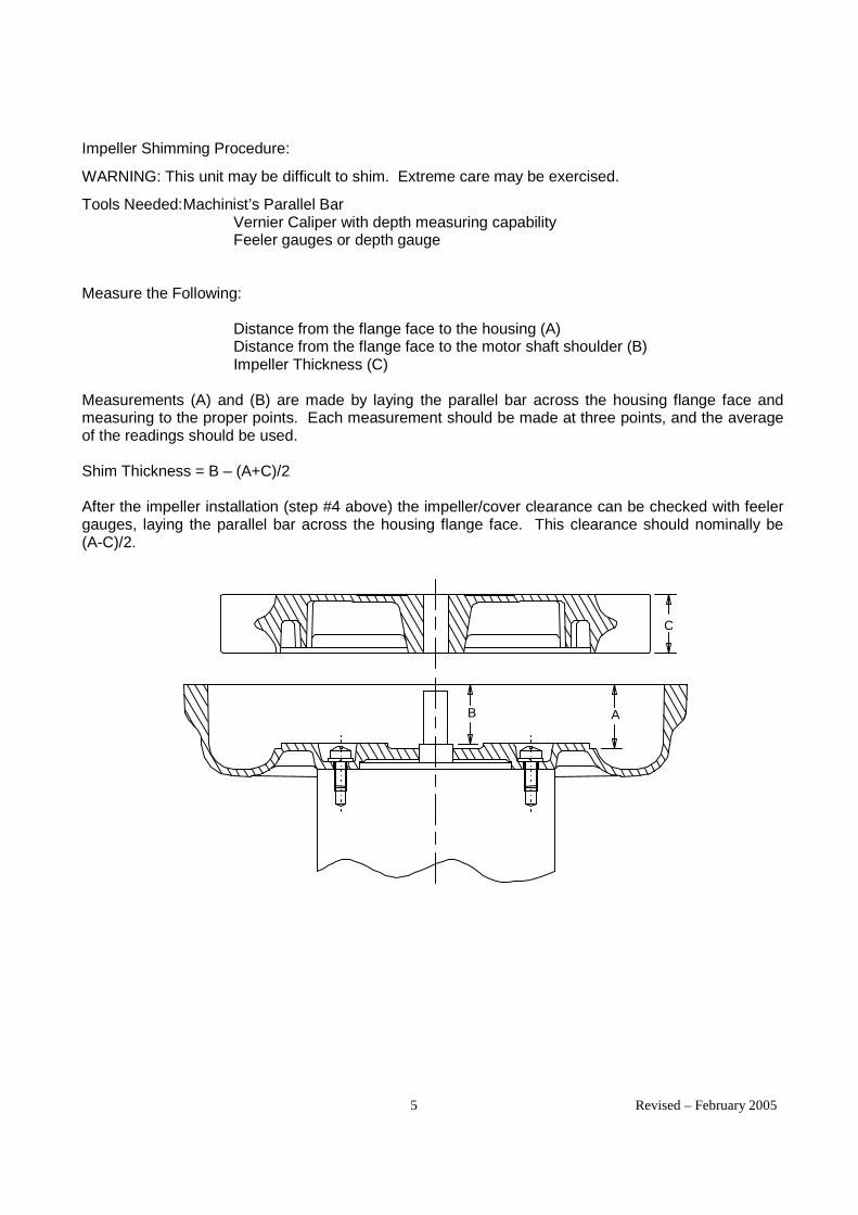
5 Revised – February 2005
Impeller Shimming Procedure:
WARNING: This unit may be difficult to shim. Extreme care may be exercised.
Tools Needed: Machinist’s Parallel Bar Vernier Caliper with depth measuring capability Feeler gauges or depth gauge Measure the Following: Distance from the flange face to the housing (A) Distance from the flange face to the motor shaft shoulder (B) Impeller Thickness (C) Measurements (A) and (B) are made by laying the parallel bar across the housing flange face and measuring to the proper points. Each measurement should be made at three points, and the average of the readings should be used. Shim Thickness = B – (A+C)/2 After the impeller installation (step #4 above) the impeller/cover clearance can be checked with feeler gauges, laying the parallel bar across the housing flange face. This clearance should nominally be (A-C)/2.
C
B A

7
A. 1∅∅∅∅, 6 WIRE
115 VAC 230 VAC
1 1 LINE 3 LINE 2 5 3 2 5
4 LINE 4 LINE
8 8
INTERCHANGE LEADWIRES 5 & 8 to REVERSE ROTATION
B. 1∅∅∅∅, 7 WIRE
115 VAC 230 VAC 1 LINE 1 LINE 3 2 2 3 4 LINE 4 8 LINE 8 5 5 9 9
INTERCHANGE LEADWIRES 5 & 8 to REVERSE ROTATION
C. 3∅∅∅∅, 9 WIRE
230 VAC 460 VAC LINE 1 LINE 1 LINE 7 2 LINE 3 2 LINE 8 4 7 3 LINE 9 5 8 4 5 6 6 9
INTERCHANGE ANY TWO LEAD LINES TO REVERSE ROTATION
D. 1∅∅∅∅, EMERSON 1/8 HP MOTOR
115 VAC 230 VAC P1/BLUE LINE P1/BLUE LINE
P2/BROWN 5/BLACK 5/BLACK 3/ORANGE
3/ORANGE 2/WHITE 4/YELLOW P2/BROWN INSULATE
2/WHITE LINE 4/YELLOW
LINE
RED RED
INTERCHANGE RED AND BLACK TO REVERSE ROTATION
E. 1∅∅∅∅, SPA DUTY WITH TERMINAL STRIPS
LOW 115 VAC HIGH 230 VAC
BROWN B B WHITE B LINE LINE L1 L1
WHITE L2 LINE L2 LINE BROWN A A
G. 3∅∅∅∅, 575 VAC 1 LINE 2 LINE 3 LINE INTERCHANGE ANY TWO LEAD LINES TO REVERSE ROTATION
F. 1∅∅∅∅, 230 VAC SINGLE VOLTAGE
1 LINE 5 4 LINE 8 INTERCHANGE LEAD
WIRES 5 & 8 TO REVERSE ROTATION
WIRING DIAGRAMS, TEFC and ODP MOTORS


DR 068/083/101Service and Parts Manual
Model: DR068DJ9Y DR068DJ9Y DR083DC9Y DR101 DR101 DR101Part No.: 037143037143037143037143 037326037326037326037326 036862036862036862036862 036244036244036244036244 038936 037252037252037252037252
081657 081572 036245036245036245036245 038937
036672036672036672036672 038938
OBSOLETEOBSOLETEOBSOLETEOBSOLETE OBSOLETEOBSOLETEOBSOLETEOBSOLETE OBSOLETEOBSOLETEOBSOLETEOBSOLETE
Item No.
Qty. Req'd Description
M3 1 Key Motor Shaft 155045 155045 155045 511501 511501 155045B1 4 Screw, Flange Not Used Not Used Not Used 120325 120262 120262B2 6 Screw, Manifold 155477 Not Used 155477 120303 155423 120303B3 2 Flange Not Used Not Used Not Used 515212 510480 515212B4 1 Housing See next page 516714 515709 510347 550421 516616B5 4 Screw, Hsg /Motor See next page 155043 121925 121925 121925 121925B6 4 Muffler Material 515779 (2 pcs)516720 516427 510544 (6 Pcs)510544 510544B7 1 Manifold Plate 516373 Not Used 515654 510541 510541 510541B8 * Shim .002" 516360 510360 516360 510494 510494 516360
* Shim .005" 516361 510361 516361 510495 510495 516361* Shim .010" 516362 510362 516362 510496 510496 516362* Shim .020" Not Used Not Used Not Used 155411 155411 155411* Shim .030" Not Used Not Used Not Used 155412 155412 155412
B9 1 Impeller 516631 516631 516416 510351 550410 516617B10 1 Bolt, Impeller 155551 155551 155551 120118 120118 120237B11 1 Lockwasher, Impeller 251690 251690 251690 120203 120203 251690B12 1 Washer, Impeller 595332 595332 595332 Not Used Not Used Not UsedB13 1 Cover 515778 516718 515698 510349 550623 510349B14 6 Screw, Cover (5 pcs)155424 (5 pcs)120231 (5 pcs)155424 120232 155424 120232B16 1 Spacer, Impeller Bolt Not Used Not Used Not Used 510355 510355 155115B17 4 Lockwasher, Housing See next page 140009 140009 120203 120203 140009B18 Screen, Muffler Retaining Right (**) Not Used Not Used Not Used Not Used Not Used Not Used
Screen, Muffler Retaining, Left (**) Not Used Not Used Not Used Not Used Not Used Not UsedB19 Bolt, Muffler Hsg/Hsg Not Used Not Used Not Used Not Used Not Used Not UsedB20 Muffler Housing Not Used Not Used Not Used Not Used Not Used Not Used
Bolt, Motor/Muffler Not Used Not Used Not Used Not Used Not Used Not UsedLockwasher, Motor/Muffler Not Used Not Used Not Used Not Used Not Used Not UsedWasher, Motor/Muffler Not Used Not Used Not Used Not Used Not Used Not UsedSpacer, Motor/Muffler Not Used Not Used Not Used Not Used Not Used Not Used
Parts Breakdown
*As needed **Viewed looking at inlet/outlet ports 11/10/10 Rev. F

Part # Motor Wiring Specific PartsDR068DJ9Y 81657 552391 see motor
037143 515729 D
037326 515730 D081572 552391
036862 515729 D
037252 515729 D036244 510498 A036245 517356 C036672 515211 G038939 515729 D038936 510498 A038937 510501 C038938 516610 G
Bearing,Rear (M1) Bearing,
Not Replaceable Not Replaceable
Not Replaceable Not Replaceable
B4 552411, B5 251493 B17 120203B4 515784, B5 155043, B17 140009
510449 510449
Not Replaceable Not Replaceable
510449 510449
Model
DR068DJ9Y
DR068DJ9Y
DR083DC9Y
DR101DC9DR101BX9
DR083DC9Y
DR101BX72DR101BX86DR101DC9MDR101BX9MDR101BX72MDR101BX86M
B4 552412,B5 251493,B17 120203B4 515709, B5 121925, B17 140009
see motor
*As needed **Viewed looking at inlet/outlet ports 11/10/10 Rev. F

DR101038939
155045120262155423510480550423155043
(6 Pcs)510544510541516360516361516362
Not UsedNot Used
550412120237251690
Not Used550623155424155115140009
Not UsedNot UsedNot UsedNot UsedNot UsedNot UsedNot UsedNot Used
*As needed **Viewed looking at inlet/outlet ports 11/10/10 Rev. F

Bearing,
Not Replaceable
Not Replaceable
510449
Not Replaceable
510449
*As needed **Viewed looking at inlet/outlet ports 11/10/10 Rev. F

DR 202/202M/303/353/353MService and Parts Manual
Model: DR202 DR202M DR303 DR303 DR353 DR353MPart No.: 037066 080564 036699036699036699036699 038841 037146037146037146037146 080554
037067 080565 036698036698036698036698 038842 037147037147037147037147 080555
036373 080566 037207037207037207037207 038843 037148037148037148037148 080556
OBSOLETEOBSOLETEOBSOLETEOBSOLETE OBSOLETEOBSOLETEOBSOLETEOBSOLETE
Item No.
Qty. Req'd Description
M3 1 Key Motor Shaft 511501 511501 511501 511501 515582 510629B1 4 Screw, Flange 120214 155425 120162 155425 120162 120162B2 6 Screw, Manifold 155477 155423 120303 155423 155477 155130B3 2 Flange 510480 510493 510493 510493 510493 510962B4 1 Housing 510341 550173 510335 550173 516364 517002B5 4 Screw, Hsg /Motor 120235 121925 121925 121925 121925 155128B6 4 Muffler Material 510485 550186 510488 550186 516384 (6 pcs) 517015B7 1 Manifold Plate 510478 Not Used 510487 Not Used 516347 517008B8 * Shim .002" 510494 510494 510494 510494 510494 510356
* Shim .005" 510495 510495 510495 510495 510495 510357* Shim .010" 510496 510496 510496 510496 510496 510358* Shim .020" 155411 155411 155411 155411 155411 510359* Shim .030" 155412 155412 155412 155412 155412 Not Used
B9 1 Impeller 510345 551222 510339 529888 516318 551223B10 1 Bolt, Impeller 120118 120214 120118 120214 120325 120214B11 1 Lockwasher, Impeller 120203 120203 120203 120203 120203 120203B12 1 Washer, Impeller Not Used Not Used Not Used Not Used Not Used Not UsedB13 1 Cover 510343 550132 510337 550132 516329 516990B14 6 Screw, Cover 155424 155424 120232 155424 (5 pcs)155129 155129B16 1 Spacer, Impeller Bolt 510355 510355 510355 510355 510355 510355B17 4 Lockwasher, Housing 120203 120203 120203 120203 120203 251787B18 Screen, Muffler Retaining Right (**) Not Used Not Used Not Used Not Used Not Used 517016
Screen, Muffler Retaining, Left (**) Not Used Not Used Not Used Not Used Not Used 517016B19 Bolt, Muffler Hsg/Hsg Not Used Not Used Not Used Not Used Not Used Not UsedB20 1 Muffler Housing Integral 550170 Integral 550170 Not Used Not Used
Bolt, Motor/Muffler Not Used Not Used Not Used Not Used Not Used Not UsedLockwasher, Motor/Muffler Not Used Not Used Not Used Not Used Not Used Not UsedWasher, Motor/Muffler Not Used Not Used Not Used Not Used Not Used Not Used
Parts Breakdown
*As needed **Viewed looking at inlet/outlet ports 11/10/10 Rev. G

Spacer, Motor/Muffler Not Used Not Used Not Used Not Used Not Used Not Used
*As needed **Viewed looking at inlet/outlet ports 11/10/10 Rev. G

Part # MotorWiring
DiagramBearingRear (M1
Bearing,Impeller End
(M2)DR202Y9 037066 510498 ADR202Y72 037067 510501 CDR202Y86 036373 516610 GDR202Y9M 080564 510498 ADR202Y72M 080565 510501 CDR202Y86M 080566 510933 GDR303AE9 036699 517355 ADR303AE72 036698 517356 CDR303AE86 037207 516610 GDR303AE9M 038841 517355 ADR303AE72M 038842 517356 CDR303AE86M 038843 516610 GDR353BR86 037146 510934 GDR353BR9 037147 510499 ADR353BR72 037148 510502 CDR353BR86M 080556 551237 GDR353BR9M 080554 551235 ADR353BR72M 080555 551236 C
510449 510449
ModelSpecific
Parts
*As needed **Viewed looking at inlet/outlet ports 11/10/10 Rev. G

Solberg – Where the Best is in Store for You!
APPLICATIONS & EQUIPMENT
FEATURES & SPECIFICATIONS
OPTIONS (Inquiries Encouraged)
CONFIGURATION DRAWING
1151 Ardmore Ave. Itasca, IL 60143 USA Tel: 630/773-1363 Fax: 630/773-0727
E-mail: [email protected] Web Site: www.solbergmfg.com
with with FPT Rated Flow SCFMPolyester Paper Inlet & DIMENSIONS - inches Nominal Element Approx.Element Element Outlet A B C D E F G Rating Rating Wt. lbs
I CSL-825-038HC CSL-824-038HC 3/8" 3 5/8 9/16 3 3/4 1 7/8 9/16 3 1/2 3 18 25 0.88I CSL-825-050HC CSL-824-050HC 1/2" 3 5/8 9/16 3 3/4 1 7/8 9/16 3 1/2 3 18 25 0.88I CSL-843-050HC CSL-842-050HC 1/2" 4 3/8 9/16 5 7/8 2 1/2 9/16 5 3 1/4 20 55 3I CSL-825-075HC CSL-824-075HC 3/4" 3 3/4 9/16 3 3/4 1 7/8 9/16 3 1/2 3 24 25 0.88S CSL-843-075HC CSL-842-075HC 3/4" 4 3/8 9/16 5 7/8 2 1/2 9/16 5 3 1/4 25 55 3I CSL-843-100HC CSL-842-100HC 1" 4 3/8 3/4 5 7/8 2 5/8 3/4 5 3 1/4 35 55 3S CSL-849-100HC CSL-848-100HC 1" 6 1/2 3/4 7 5/16 4 1/4 3/4 6 13/16 5 1/4 40 115 5I CSL-843-125HC CSL-842-125HC 1 1/4" 4 3/8 3/4 5 7/8 2 5/8 3/4 5 3 1/4 55 55 3S CSL-849-125HC CSL-848-125HC 1 1/4" 6 1/2 3/4 7 5/16 4 1/2 3/4 6 13/16 5 1/4 60 115 5I CSL-849-150HC CSL-848-150HC 1 1/2" 6 1/2 3/4 7 5/16 4 1/2 3/4 6 13/16 5 1/4 80 115 5I CSL-851-200HC CSL-850-200HC 2" 10 1/4 3/4 8 3/4 5 3/4 7 5/8 9 1/4 175 290 15I CSL-851-250HC CSL-850-250HC 2 1/2" 10 1/2 1 1/4 8 3/4 5 1/2 1 1/4 7 5/8 9 1/4 210 290 15I CSL-239-300C* CSL-238-300C* 3" 15 3/4 2 7/8 13 1/4 8 7/8 2 7/8 12 11 300 570 33
CSL14-304 pg. 2
INLE
T VA
CU
UM
FIL
TER
S C
SL, C
T, V
L, V
S, L
RS
Serie
s
SMALL COMPACT INLET VACUUM FILTERS "CSL" Series 3/8” - 3” FPT
Vacuum Pumps & Systems – P.D., Side Channel, Rotary Vane, Screw, Piston Vacuum Packaging Equipment Vacuum Lifters Blowers - Side Channel & P.D.
Intake Suction Filters Pneumatic Conveying Systems Soil Venting/Remediation Remote Installations for Piston
& Screw Compressors
Printing Industry Factory Automation Equip Leak Detection Systems Woodworking Medical Industry
Vacuum gauge available Dome hood for high holding capacity Available in Stainless Steel
Vacuum level: Typically 1x10⁻³ mmHg (1.3x10⁻³ mbar) Polyester: 99%+ removal efficiency standard to 5 micron Paper: 99%+ removal efficiency standard to 2 micron Brazed fittings for High vacuum duty Stainless steel torsion clips for durability Low pressure drop Positive engagement O-ring seal system Fully-drawn one piece canister
Large dirt holding capacity and Easy field cleaning, especially when mounted horizontally or inverted Rugged all steel construction w/baked enamel finish Various media Temp (continuous): min -15°F (-26°C ) max 220°F (104°C ) Filter change out differential: 10” - 15” H2O over initial delta P Pressure drop graphs available upon request
Epoxy coated housings Activated carbon prefilter for odor Support brackets
Alternate top-to-canister fastening system for low pressure or pulsating systems
Dimension tolerance + 1/4”
*1/4" taps standard on inlet and outlet
CSL 824-851 Series
CSL 239/238 Series
I = Industrial Duty S = Severe Duty


Filter Element 020806.doc 2/9/06
460 West Gay StreetWest Chester, PA 19380
610-692-5650 Fax [email protected]
Gasho Replacement Inlet Filter Elements
High quality replacement elements are available for the filters of various manufactures used on packages built by Gasho. Paper elements are normally used in inlet filters and replaced when they are dirty. Polyester elements are cleanable.
FilterSize, In. Gasho
Filter #Box
Quantity
O.D. I.D. Ht. ListPrice
1 GA-0470 6 5-13/16 4 2 $17.002 GA-0471 6 5-13/16 4 2-1/2 $17.00
2.5-3 GA-0472 2 9-3/4 7-1/4 4 $23.004 GA-1063 2 9-3/4 7-1/4 6 $27.005 GA-0474 1 11-1/2 9-7/8 7 $35.006 GA-0475 1 13-5/8 11-5/8 8-5/8 $53.00
8-12 GA-1163 1 17 13 10 $185.00
GA-0471 Elements are frequently used to replace GA -0470
Manufacturer Cross Reference
GashoFilter #
UniversalFilter #
EM Prod.Filter #
Full-OnFilters #
Solberg #
GA-0470 81-0470 FOF810470 32-00GA-0471 81-0471 P-642 FOF810471 32-02GA-0472 81-0472 P-974 FOF810472 32-04GA-1063 81-1063 P-976 FOF811063 32-06GA-0474 81-0474 P-1197 FOF810474 32-08GA-0475 81-0475 P-13118 FOF810475 32-10GA-1163 81-1163 P-171310 FOF811163 32-12

IPG’s 64 series brass ball valves comply with the latesteditions of these published standards:
• AGA Z21.15.CGA9.1 • ASME/ANSI B16.38 • AGA No. 3-88 • MSS SP-110 • ANSI B1.20.1 •UL Guide YSDT • ANSI B16.18 •UL Guide YRPV• CAN/CGA-3.16-M88 •UL Guide VQGU• ASME/ANSI B16.33 •
A
B
C
D
A
B
C
D
Your local Conbraco distributor is:
Apollo®, RP&C and Conbraco are a registered trademarks of Conbraco Industries Inc. which reserves the right to change specificationswithout notice.©2002 Conbraco Industries Inc.
P.O. Box 247 Matthews, NC 28106
(704) 841-6000Fax: (704) 841-6020http://www.conbraco.com
Standards Compliance
Description Materials 1. Body Brass UNI 5705-652. Retainer Brass UNI 5705-653. Ball Brass UNI 5705-654. Seats PTFE5. Stem Seals PTFE 6. O-Ring NBR 75 Shore A 7. Packing Gland Brass UNI 5705-658. Nut Plated Steel9. Stem Brass UNI 5705-65 Cr Plated
10. Lever Handle Plated Steel 1/4" - 2" ModelsAluminum 2 1/2" - 4" Models
Size Part No. A B C D (Cv) 1/4" NPT 64-101-01 0.39 2.02 1.75 3.85 63/8" NPT 64-102-01 0.39 2.02 1.75 3.85 71/2" NPT 64-103-01 0.59 2.44 1.88 3.85 193/4" NPT 64-104-01 0.78 2.71 2.28 4.80 341" NPT 64-105-01 0.98 3.07 2.44 4.80 501-1/4" NPT 64-106-01 1.25 3.42 3.07 6.02 1041-1/2" NPT 64-107-01 1.57 3.89 3.34 6.02 2682" NPT 64-108-01 1.96 4.33 3.79 6.37 3092-1/2" NPT 64-109-01 2.56 5.59 5.02 8.07 6293" NPT 64-100-01 3.15 6.45 5.45 8.07 10184" NPT 64-10A-01 3.94 7.60 6.34 10.23 1622
600
400
300
200
100
-20 0 50 100 150 200 250 300 350 400Temperature (F˚)
Pressure
Materials of Construction
64-100 Dimensional Data Size Part No. A B C D (Cv) 1/2" 64-203-01 0.59 2.53 1.88 3.85 193/4" 64-204-01 0.78 2.99 2.28 4.80 341" 64-205-01 0.98 3.58 2.44 4.80 501-1/4" 64-206-01 1.25 4.09 3.07 6.02 1041-1/2" 64-207-01 1.57 4.56 3.34 6.02 2682" 64-208-01 1.96 5.43 3.79 6.37 3092-1/2" 64-209-01 2.56 6.93 5.02 8.07 6293" 64-200-01 3.15 8.09 5.45 8.07 1018
64-200 Dimensional Data
Optional KitsValve Size Locking Handle Stem Extensions Balancing Stops1/4", 3/8" & 1/2" 78-1659-01 78-1501-0 78-1506-013/4" & 1" 78-1660-01 78-1502-0 78-1507-011-1/4" & 1-1/2" 78-1661-01 78-1503-0 78-1508-012" 78-1662-01 78-1504-0 78-1509-012-1/2" & 3" - 78-1505-0 78-1510-01
PHFL64S 4/02CG 7.5M Printed in U.S.A.
NOTE: Specify (-07) suffix for T-Handle i.e. 64-105-07.
64-100 Series
I n t e r n a t i o n a lA Division of Conbraco Industires, Inc.

Bulletin 71.4:289
D10
0154
X01
2
08/90
Regulators www.FISHERregulators.com
289 Series Spring-Loaded Relief Valves
The 289 Series relief valve is a throttling relief valveused downstream of pressure regulators to protect thedownstream system from overpressure. A smooththrottling action minimizes pressure surges in thesystem during emergency operation. These relief valvesare available in 1/4, 3/4, 1, or 2-inch sizes with springranges (relief pressure settings) from 5 inches w.c. to75 psig (0.01 to 5.2 bar).
All sizes above 1/4-inch feature a pitot tube booster(figure 1) for achieving the highest possible reliefcapacity with a minimum buildup of system pressure.When the valve is opening, high gas velocity throughthe orifice creates an area of relatively low pressurenear the end of the pitot tube. This pitot tube effectforms a partial vacuum above the diaphragm whichhelps to open the valve.
The relief valve diaphragm functions as a valve disk tocontrol flow in all types except the 289H and 289HH,which use O-ring seats. The nitrile or neoprene seating
surfaces provide tight shutoff. The 289 Series relief valvesare ideal for low pressure settings due to the increasedsensitivity provided by the large diaphragm area.
Features
• Throttling Type Relief—Smooth, sensitive throttlingaction minimizes pressure surges.
• High Flow Rates—As shown by the figure 4capacity curves, high flow rates can be achieved withminimum pressure buildup due to the boosting systemwhich increases the relief valve opening.
• Small Size—The 289 Series relief valves are smalland compact, making them suitable for areas limitedin space.
• Reliability Due to Simplicity—A single internal as-sembly decreases the possibility of mechanical failure.
Figure 1. Type 289H and 289HH Relief Valves
1-INCH TYPE 289H AND 289HH 2-INCH TYPE 289H
W1870-2
W1870-2
W0210-1W0209-2

Bulletin 71.4:289
2
Available ConfigurationsType 289A (figure 2): 1/4-inch spring-loaded reliefvalve for relief pressure settings of 3 to 22 psig,(0.21 to 1.5 bar) two spring rangesType 289H (figure 1): 1 or 2-inch spring-loadedrelief valve for relief pressure settings of 1 to 50psig (0.07 to 3.5 bar) four spring ranges, in the1-inch size and of 7-inches w.c. to 10 psig, (0.02 to0.69 bar), four spring ranges, in the 2-inch sizeType 289HH (figure 1): 1-inch spring-loaded reliefvalve for relief pressure settings of 45 to 75 psig(3.1 to 5.2 bar)Type 289L (figure 3): 3/4 or 1-inch spring-loadedrelief valve for relief pressure settings of 10 to40-inches w.c., (0.03 to 0.1 bar), two spring rangesType 289U (figure 2): 1/4-inch spring-loaded reliefvalve for relief pressure settings of 5-inches w.c. to3 psig, (0.01 to 0.21 bar), two spring ranges
Inlet ConnectionsType 289L: 3/4 or 1-inch NPT femaleTypes 289A and 289U: 1/4-inch NPT femaleType 289H: 1 or 2-inch NPT femaleType 289HH: 1-inch NPT female
Outlet (Vent) ConnectionsSame size as inlet connection
Maximum Allowable Relief (Inlet) Pressure(1) andMaximum Relief Set Pressure
See table 1
Capacity DataSee figure 4
Standard Construction MaterialsValve Body and Spring CaseTypes 289A and 289U: ZincType 289H (1-inch), 289HH, and 289L: AluminumType 289H (2-inch): Cast iron body with aluminumspring caseDiaphragmType 289A: NeopreneTypes 289H and 289HH: Nitrile or fluoroelastomerAll Others: Nitrile
1. The pressure/temperature limits in this bulletin and any applicable standard limitation should not be exceeded.2. Bubble-tight shutoff can not be attained at settings below 5 psig with fluoroelastomer O-ring seat.
Specifications
OrificeTypes 289A and 289L: AluminumType 289H (2-inch Only): Brass or Stainless steelO-Ring Seat (Types 289H and 289HH Only):Nitrile or Fluoroelastomer(2)
O-Ring Seat Holder and Washer (1-inch Types289H and 289HH Only): AluminumSeat Washer (2-inch Type 289H Only): StainlesssteelPitot TubeTypes 289H and 289HH (1-inch), and 289L:AluminumType 289H (2-inch): Brass or Stainless steelGasketsType 289L: NeopreneAll Others: CompositionSpring: Zinc-plated steelDiaphragm PlateTypes 289A and 289U: ZincAll Others: Zinc-plated steelClosing CapType 289L: Plastic, Aluminum, or ZincType 289H (2-inch): Zinc
Material Temperature Capabilities(1)
With Nitrile and Neoprene Elastomers:–20 to150°F (–29 to 66°C)With Fluoroelastomers: 20 to 300°F (–7 to 149°C)Available with Types 289H and 289HH only
Approximate Shipping WeightTypes 289A and 289U: 0.75 lb (0.34 kg)Type 289H1-inch Size: 4 lb (1.8 kg)2-inch Size: 15 lb (6.8 kg)Type 289HH: 4 lb (1.8 kg)Type 289L: 1.5 lb (0.7 kg)
Options• TFE diaphragm protector (Types 289A and
289U only)• wire-seal on closing cap (1-inch Type 289L only)

Bulletin 71.4:289
3
Figure 2. Type 289U Relief Valve (Also Typical of Type 289A Relief Valve)
Figure 3. Type 289L Relief Valve
W1870-2 W0212-1
W1870-2W0203-1

Bulletin 71.4:289
4
Figure 4. Capacity for 0.6 Specific Gas at 14.7 Psia and 60° F
1” TYPE 289HVENT SCREEN INSTALLED
50 PSIG1D745527142
40 PSIG1D745527142
30 PSIG1D745527142
20 PSIG1D745527142
A
B
C
D
A—15 PSIG1D751527022
B—10 PSIG1D892327022
C—4 PSIG
D—1 PSIG1F826927052
INL
ET
PR
ES
SU
RE
—P
SIG
70
60
50
40
30
20
10
00 10 20 30 40 50 60 70 80
0.6 SPECIFIC GRAVITY GAS FLOW RATE—THOUSAND CUBIC FEET PER HOUR—14.7 PSIA AT 60°F
0.6 SPECIFIC GRAVITY GAS FLOW RATE—THOUSAND CUBIC FEET PER HOUR—14.7 PSIA AT 60°F
INL
ET
PR
ES
SU
RE
—P
SIG
16
14
12
10
8
6
4
2
00 4 8 12 16 20 24 28 32 36 40 44 48 52 56 60 64
10 PSIG1B536927052
7 PSIG1B536827052
5 PSIG1B536827052
2 PSIG1B536627052
1 PSIG1B536627052
1/2 PSIG1B536527052
2” TYPE 289HNO VENT RESTRICTION 1
NOTE: 1 LESS THAN 5% CAPACITY LOSS CAN BE EXPECTED WITH THE VENT SCREENINSTALLED ON THE 2-INCH TYPE 289H AT MAXIMU FLOW.2. WHEN SELECTING ANY RELIEF VALVE FOR INSTALLATION DOWNATREAM OF AREGULATOR, THE CAPACITY OF THE RELIEF VALVE SHOULD BE COMPARED WITH THEWIDE-OPEN CAPACITY OF THE REGULATOR.3. BUBBLE POINT RELIEF SETTING AND SPRING PART NUMBER ARE NOTED ONEACH CURVE.4. TO CONVERT TO EQUIVALENT CAPACITIES OF OTHER GASES, MULTIPLY VALUESOBTAINED FROM CURVE BY THE FOLLOWING FACTORS: AIR–0.78, PROPANE–0.628,BUTANE–0.548, NITROGEN–0.789B2309

Bulletin 71.4:289
5
Figure 4.Capacity for 0.6 Specific Gas at 14.7 Psia and 60° F (Continued)
INL
ET
PR
ES
SU
RE
—P
SIG
100
90
80
70
60
50
400 10 20 30 40 50 60 70 80
0.6 SPECIFIC GRAVITY GAS FLOW RATE—THOUSAND CUBIC FEET PER HOUR—14.7 PSIA AT 60°F
0.6 SPECIFIC GRAVITY GAS FLOW RATE—THOUSAND CUBIC FEET PER HOUR—14.7 PSIA AT 60°F
INL
ET
PR
ES
SU
RE
—P
SIG
0 10 20 30 40 50 60 70 80 90 100 110 120
NOTE:1. WHEN SELECTING ANY RELIEF VALVE FOR INSTALLATION DOWNATREAM OF AREGULATOR, THE CAPACITY OF THE RELIEF VALVE SHOULD BE COMPARED WITH THEWIDE-OPEN CAPACITY OF THE REGULATOR.2. BUBBLE POINT RELIEF SETTING AND SPRING PART NUMBER ARE NOTED ONEACH CURVE.3. TO CONVERT TO EQUIVALENT CAPACITIES OF OTHER GASES, MULTIPLY VALUESOBTAINED FROM CURVE BY THE FOLLOWING FACTORS: AIR–0.78, PROPANE–0.628,BUTANE–0.548, NITROGEN–0.789
100
90
80
70
60
50
40
60 PSIG
50 PSIG
75 PSIG
1” TYPE 289HHVENT SCREEN INSTALLEDSPRING 1D745527142
60 PSIG
50 PSIG
75 PSIG
1” TYPE 289HHNO VENT RESTRICTIONSPRING 1D745527142
B2310

Bulletin 71.4:289
6
Figure 4. Capacity for 0.6 Specific Gas at 14.7 Psia and 60° F (Continued)
INL
ET
PR
ES
SU
RE
—P
SIG
5
4
3
2
1
0
0 100 200 300 400 500 600 700
0.6 SPECIFIC GRAVITY GAS FLOW RATE—THOUSAND CUBIC FEET PER HOUR—14.7 PSIA AT 60°F
0.6 SPECIFIC GRAVITY GAS FLOW RATE—THOUSAND CUBIC FEET PER HOUR—14.7 PSIA AT 60°F
INL
ET
PR
ES
SU
RE
—P
SIG
4
3
2
1
0
24 IN. WC
2 IN. WC0F058227022
7 IN. WC0V060227022
3 PSIG0F058227022
NOTE: 1. WHEN SELECTING ANY RELIEF VALVE FOR INSTALLATION DOWNATREAM OF AREGULATOR, THE CAPACITY OF THE RELIEF VALVE SHOULD BE COMPARED WITH THEWIDE-OPEN CAPACITY OF THE REGULATOR.2. BUBBLE POINT RELIEF SETTING AND SPRING PART NUMBER ARE NOTED ONEACH CURVE.3. TO CONVERT TO EQUIVALENT CAPACITIES OF OTHER GASES, MULTIPLY VALUESOBTAINED FROM CURVE BY THE FOLLOWING FACTORS: AIR–0.78, PROPANE–0.628,BUTANE–0.548, NITROGEN–0.789
TYPE 289U
2 PSIG0F058227022
0 1000 2000 3000 4000 5000 6000 7000 8000 9000 10,000
INL
ET
PR
ES
SU
RE
—IN
CH
ES
W.C
.
111
83
55
28
0
INL
ET
PR
ES
SU
RE
—IN
CH
ES
W.C
.
138
111
83
55
28
0
1 PSIG(28 IN. W.C.)1B413727022
3/4” AND 1” TYPE 289LVENT SCREEN INSTALLED
3/4” SIZE
1” SIZE
1/2 PSIG (14 IN. WC) 1B413627222
B2311

Bulletin 71.4:289
7
Installation
The 289 Series relief valves may be installed in anyposition. However, the outlet connection must beprotected against the entrance of rain, snow, insects, orany other foreign material that may plug the outlet oraffect the opening and closing of the valve (see figure5). If it is necessary to pipe away the outlet, remove theoutlet screen (if one is present).
Flow through the valve must be as indicated by the flowdirection arrow on the body (inlet connection is markedon some sizes).
The spring case vent on the 2-inch Type 289H is tappedand plugged. This vent opening must remain plugged toallow the pitot tube booster to function.
Overpressure
Overpressure conditions in a regulating system maycause personal injury or equipment damage due tobursting of pressure-containing parts or explosion of
accumulated gas. Check the system for damage if anyof the maximum allowable relief (inlet) pressure ratingsin table 1 are exceeded.
Ordering Information
When ordering, specify:
1. Type number and size
2. Relief pressure range and setting desired
3. Type of gas (natural gas, air, etc.); list any factorssuch as impurities in the gas that may affect compat-ibility of the gas with valve trim parts
4. Temperature and specific gravity of the gas
5. Maximum relief (inlet) pressure and flow rate desired
6. Line size and end connection size of adjacent piping
7. For Types 289H and 289HH, specify material ofdiaphragm and O-ring seat; for 2-inch Type 289H,specify material of orifice and pitot tube
8. Options desired, if any
Table 1. Spring Ranges and Maximum Allowable Relief (Inlet) Pressures
,SEZISYDOBSEHCNI
EPYTEGNARGNIRPS
)SGNITTESERUSSERPFEILER(TRAPGNIRPS
REBMUNELBAWOLLAMUMIXAM
GNITTESFEILER )1(
ELBAWOLLAMUMIXAM)TELNI(FEILER
ERUSSERP )2(
4/1U982
.c.wsehcni-52ot5gisp3ot.c.wsehcni-02
)rabm26ot21()rab12.0otrabm05(
220722060V0220722850F0
)rab12.0(gisp3 )rab96.0(gisp01
A982gisp31ot3gisp22ot11
)rab9.0ot12.0()rab5.1ot67.0(
220723650Z0220722862B1
)rab25.1(gisp22 )rab1.3(gisp54
1ro4/3 L982
.c.wsehcni-8ot3
.c.wsehcni-81ot5
.c.wsehcni-81ot01
.c.wsehcni-04ot21
)rabm02ot7()rabm54ot21()rabm54ot52()rabm99ot03(
220725314B12100X2113N1210X7197A31210X6197A31
)rabm99(.c.wsehcni-04 )rab25.0(gisp7
1 H982
gisp5.4ot1gisp51ot4gisp02ot01gisp05ot51
)rab3.0ot960.0()rab0.1ot82.0()rab4.1ot96.0(
)rab4.3ot0.1(
250729628F1220723298D1220725157D1241725547D1
)rab4.3(gisp05 )rab9.6(gisp001
2 H982
.c.wsehcni-81ot7gisp52.2ot5.0gisp7ot57.1gisp01ot4
54ot71( rabm ))rab61.0ot430.0(
)rab25.0ot21.0()rab96.0ot82.0(
250725635B1250726635B1250728635B1250729635B1
)rab96.0(gisp01 )rab7.1(gisp52
1 HH982 gisp57ot54 )rab2.5ot1.3( 241725547D1 )rab2.5(gisp57 )rab9.6(gisp001
.elbaliavaegnargnirpstsehgihhtiW.1.pudliubsulpgnitteserusserpfeilermumixaM.2

©Fisher Controls International, Inc., 1970, 1990; All Rights Reserved
Fisher and Fisher Regulators are marks owned by Fisher Controls International, Inc. The Emerson logo is a trade mark and service mark of Emerson Electric Co.All other marks are the property of their respective owners.
The contents of this publication are presented for informational purposes only, and while every effort has been made to ensure their accuracy, they are not to be construed as warranties or guarantees, expressor implied, regarding the products or services described herein or their use or applicability. We reserve the right to modify or improve the designs or specifications of such products at any time without notice.
For information, contact Fisher Controls:Marshalltown, Iowa 50158 USA28320 Gallardon, FranceSao Paulo 05424 BrazilSingapore 128461
Printed in U.S.A.
Bulletin 71.4:289
Regulatorswww.FISHERregulators.com
Figure 5. Typical Installation of a 289 Series Relief Valve
Figure 6. Dimensions
INCHES(mm)
TYPE 289H AND 289HH (1-INCH) TYPE 289H (2-INCH)
1.88(48)
1.78(46)
8.69(221)
0.38(10)
4.12(105)
2.12(54)
3.56(91)
7.12(181)
8.94(228)
TYPE 289L (3/4 AND 1-INCH)
4.88(124)
5.38(137)
1.94(50)
1.25(32)
TYPE 289A AND 289U (1/4-INCH)
3.06D(77.7)
0.38(9.7)
2.25(57.2)
1/4-18 NPT
11B6509-BAL5113-BAF8621-FAU2493-BA1393-2
PROTECTIVE VENT PIPEWITH RAIN CAP
2” TYPE 289HRELIEF VALVE
LARGE SERVICEREGULATOR
AJ4698-CA1947-1

Pressure and Vacuum Gauges 7-21-00.doc
Pressure and Vacuum Gauges We use both standard gauges and liquid filled gauges from a variety of manufacturers. Gauges are installed on our packages with gauge isolation valves (gauge cocks) part number BRS-VA-025-4F4M-BT. The gauge isolation valve can be used as a snubber while reading the gauge by opening it slightly. To protect gauges from damage due to shocks or pulsations in the system, gauge isolation valves should be closed except when the gauge is being read. Liquid filled gauges may display incorrect readings due to variations in atmospheric pressure. To determine if a gauge is subject to this condition, the liquid filled cavity should be temporarily vented to atmosphere. Most liquid filled gauges have a seal plug in the liquid filled cavity. Remove this plug to allow the cavity to be vented to atmosphere. In some instances the case can be lightly squeezed to burp it. Replace the plug.
J. E. GASHO & ASSOCIATES, INC. Authorized Manufacturer’s Representative
Air / Gas Moving Equipment 460 W. GAY STREET
WEST CHESTER, PA 19380 PHONE: 610-692-5650 FAX: 610-692-5837
2 ½” Dia. Gauge
Gauge Isolation Valve Shown in closed position
Liquid seal plug
¼” NPT


025 Series OptionsMaterial Options Brass Body, Nickel Plated Brass Ball, Teflon® Seats, Stainless Handle Screw
Seal Options Buna-N, Ethylene Propylene, Fluoroelastomer (Viton®), Neoprene
Body Options 1/4 Female x 1/4 Female NPT 1/4 Female x 11/16-16 Male1/4 Female x 1/4 Male NPT 1/4 Female x 7/16-24 Female1/4 Female x 1/8 Female NPT 1/4 Female x 1/4 Female Flare1/4 Female x 1/8 Male NPT 1/4 Female x 3/8 Compression1/4 Female x 1/4 Hose Barb
Handle Options Zinc Die Cast Lever (Standard), Zinc Die Cast Lever with Red Vinyl Sleeve, Steel Lever, Steel Lever, Round Handle,Steel Lever, Steel Lever with Red Vinyl Sleeve, Round Zinc Die Cast Handle, Black Nylon T-Handle,Blue Nylon Knob, .312 x 1” Stem, Screw Slot Headed Ball
Plating Options Electroless Nickel, Black Zinc
025 SERIES BALL VALVE
025 One-Way Ball Valve Design Considerations
The 025 Series One-Way Ball Valve compact design promotes multiple configurationsto fit the exact end use application. The 025 Ball Valve Series is rated to 500 psi andwill support flow and pressure only in the flow direction. The 025 Series has a one-piece body construction, stamped with directional flow arrows, to cover 1/4” NPT endconfiguration applications. The Zinc Die Cast Lever Handle is standard. Handles canbe ordered Reversed - to lie over the outlet when the valve is in the open position. ULconfigurations are available and rated to 250 psi. UR configurations are available andrated to 500 psi.
Example: Inlet End Outlet End Seal Handle Plating1/4 FNPT 1/4 MNPT Buna-N Steel ENP
SMC Part Number: 025-4F4M-B,SH,ENP
The handle will lie over the Inlet port when the valve is in the open position. SMCPart Numbers are a description of the valve as read left to right, Inlet to Outlet.
Example: 025-4F4M-B,SH,ENP = 1/4 FNPT Inlet x 1/4 MNPT Outlet
Maximum Operating Pressure - 500 psiMaximum Operating Temperature - 180 Degrees F Ball Through Hole Diameter - .218
SMC will quote alternate materials or customize our standard products when quantities ensure competitive pricing.Contact Customer Service at (651) 653-0599, FAX - (651) 653-0989, E-Mail - [email protected]

Accessories
Filtration - Moisture Separator
™By separating and containing entrained liquids, ROTRON’Smoisture separator helpsprotect our regenerativeblowersand the end treatment system from corrosionand mineralization damage. Recommended for allsoil vacuum extraction applications.
PLASTIC“P”DESIGN METAL“D”DESIGN METAL“B”DESIGN
SPECIFICATIONS:SEPARATION METHOD – High E�ciency CyclonicRELIEF VALVEMATERIAL – Brass& StainlessSteelFLOAT MATERIAL – CopperFLOAT SWITCH – SPDT, Explosion-proof
NEMA 7&9, 5Amp max.
Modelswithout �oat switch available. Metal MS200/ 300DSmodelsare not the standard stocked, but are available.
(OPTIONAL)
VALVE
(OPTIONAL)
O.D.INLET
(PLUGGED) SWITCH(OPTIONAL)
G
D
H
H
(PLUGGED)
C
J
B
3/4"NPT
CAPACITY(PER CHART)
EF
3.90
(OPT
ION
AL
LOW
SW
ITCH
)
SWITCH(OPTIONAL)
INLET
H
B
DJ
E
F
(OPTIONAL)
(PLUGGED)
B
VALVE
(OPTIONAL)
J
D
C
E F
G
VALVE
3/4"NPT
INLETO.D.
FLOAT SWITCH
3/4" NPT
VACUUM RELIEF
VACUUM GAUGE
1/4" NPT FLOAT LEVEL 1/4" NPT
DRAIN
WATER LEVEL
DRAIN - 1" NPT INTERNAL THD
FLOAT LEVEL
O.D.
VACUUM GAUGE
1/4" NPT
VACUUM RELIEF
VACUUM GAUGE
VACUUM RELIEF
DRAIN
TMMOISTURE SEPARATOR
RAP AT ORI SO T U R E
EM
S
"A"
"A"
INSTALL FLOAT SW.
INFO PACKET
MOISTURE SEPARATOR
TM CYCLONICACTIONCAUTION:FREEZING MAY CAUSE DAMAGE.MOISTURE SEPARATORS USED IN TEMPERATURES BELOW 32øF (0øC)MUST BE PROPERLY WINTERIZED.
"A"
T ORURE
G
OUTLETOUTLET
OUTLET
Part/Model Number
MS200PS MS300PS MS200DS MS300DS MS350BS MS500BS MS600BS MS1000BS
Specification Units 038519 038520 080086 080087 038357 080660 080659 038914
Dimension A Inchesmm
2.3860.5
2.8873.2
2.0050.8
2.5063.5
3.2582.6
3.2582.6
4.00101.6
6.00152.4
CFM Max. CFMm3/hr
200340
300510
200340
300510
350595
500850
6001020
10001700
Dimension B Inchesmm
22.46570.5
22.46570.5
22.12561.8
22.12561.8
28.00711.2
28.00711.2
27.00685.8
31.00787.4
Dimension C Inchesmm
16.00406.4
16.00406.4
16.75425.5
16.75425.5
23.00584.2
23.00584.2
23.00584.2
27.00685.8
Dimension D Inchesmm
3.2582.6
3.2582.6
2.7569.9
2.7569.9
4.00101.6
4.00101.6
4.00101.6
4.00101.6
Dimension E Inchesmm
31.05788.7
31.05788.7
27.92709.2
27.92709.2
37.25946.2
37.37949.2
37.37949.2
47.321201.9
Dimension F Inchesmm
33.30845.8
33.30845.8
30.17766.3
30.17766.3
39.501003.3
54.501384.3
54.501384.3
51.701313.2
Dimension H Inchesmm
6152.4
6.00152.4
6.56166.6
6.81173
9.75247.7
9.75247.7
9.25235
10.00254
Dimension G Inchesmm
4.50 OD114.3
4.50 D114.3
4.50 D114.3
4.50 OD114.3
4.50 OD114.3
6.63 ID168.4
6.63 ID168.4
8.62 OD218.9
Dimension J Inchesmm
13.25336.6
13.25336.6
12.62320.5
12.62320.5
17.50444.5
17.50444.5
17.50444.5
19.88505
Drain Internal Thd - 3/4 3/4 3/4 3/4 1 1 1 1
Shipping Weight LbsKg
4219.1
4219.1
4219.1
4219.1
8237.2
9543.1
9643.5
15068
G 5____
This document is for informational purposes only and should not be considered as a binding description of the products or their performance in all applications. The performance data on this page depicts typical performance under controlledlaboratory conditions. AMETEK is not responsible for blowers driven beyond factory specified speed, temperature, pressure, flow or without proper alignment. Actual performance will vary depending on the operating environment and application.AMETEK products are not designed for and should not be used in medical life support applications. AMETEK reserves the right to revise its products without notification. The above characteristics represent standard products. For productdesigned to meet specific applications, contact AMETEK Technical & Industrial Products Sales department.
AMETEK TECHNICAL & INDUSTRIAL PRODUCTS75 North Street, Saugerties, NY 12477USA: +1 215-256-6601 - Europe: +44 (0) 845 366 9664 - Asia: +86 21 5763 1258Customer Service Fax: +1 215.256.1338www.ametektip.com

Accessories
Filtration - Moisture Separator
404
ForDR/EN/CP
BlowerModel
SelectorMoistureSeparator
Model
Liquid-holdingCapacity(gallons)
Inlet(OD)
Outlet
MaxVacuum
Allow(IHG)
454 MS200PS
MS200DS
7
10
2.38 12
2.0 224.5 OD
MS300PS 7 2.88 12
MS300DS 10 2.5MS350BS
MS500BS 403.25
MS600BS 4.06.63 ID 22
MS1000BS
Pres
sure
Dro
p (IW
G)
0 100 200 300 400 500 600 700 800 900 1000 1100 1200
1
2
3
4
5
6
Flow Rate (SCFM)
65 6.0 8.62 OD
505513523555633833656
6757808
909
8581233
97914
The moisture separator shall be designed for use in a soil vapor extraction system capable of continuous operation with a pressure drop of less than six inches of water at the rated flow of _____ SCFM. The separator shall be capable of operation under various inlet conditions randing from a fine mist to slugs of water with high efficiency.
The moisture separator shall incorporate cyclonic separation to remove entrained water. The separator must protect against an overflow by fail safe mechanical means. An electrical switch or contact(s) alone is not an acceptable means of protection against overflow, but is a good backup.
The body of the moisture separator shall be constructed of heavy wall plastic or heavy gauge cold rolled steel. The steel interior and exterior shall be epoxy (powder) coated to resist abrasion, corrosion, and chipping that might expose the surface. The inlet shall be tangentially located and welded to the body. The outlet port shall be constructed of PVC or cast aluminum alloy, flanged and sealed to the center of the top of the separator. The separator shall incorporate a non-sparking copper float ball and an adjustable relief valve to protect against overflow and overheating the blower.
The moisture separator must have a liquid capacity of _____ gallons. The inlet shall be _____ inch OD slip-on type. The outlet shall be _____ inch OD slip-on type.
2.0 Moisture SeparatorTM Specifications
2.1 Duty
2.2 Principle of Operation
2.3 Construction
2.4 Capacity and Dimension
2.5 Pressure Drop
MS2
00P/
DS
MS3
00P/
DS
MS3
50BS
MS5
00BS
MS6
00BS
MS1
000BS
G 6____
This document is for informational purposes only and should not be considered as a binding description of the products or their performance in all applications. The performance data on this page depicts typical performance under controlledlaboratory conditions. AMETEK is not responsible for blowers driven beyond factory specified speed, temperature, pressure, flow or without proper alignment. Actual performance will vary depending on the operating environment and application.AMETEK products are not designed for and should not be used in medical life support applications. AMETEK reserves the right to revise its products without notification. The above characteristics represent standard products. For productdesigned to meet specific applications, contact AMETEK Technical & Industrial Products Sales department.
AMETEK TECHNICAL & INDUSTRIAL PRODUCTS75 North Street, Saugerties, NY 12477USA: +1 215-256-6601 - Europe: +44 (0) 845 366 9664 - Asia: +86 21 5763 1258Customer Service Fax: +1 215.256.1338www.ametektip.com

Your Choice. Our Commitment.
SERVICE AND PARTS MANUAL FOR
MOISTURE SEPARATORS
Technical & Industrial Products 627 Lake Street, Kent, Ohio 44240 U.S.A. Telephone: 330-673-3452 Fax: 330-677-3306 e-mail: [email protected] internet: www.ametektip.com

Revised 17 February 2005
OPERAT ION & MA IN TENANCE MANUAL
Technical & Industrial Products 627 Lake Street, Kent, Ohio 44240 U.S.A. Telephone: 330-673-3452 Fax: 330-677-3306
Rotron Moisture Separator Thank you for purchasing an AMETEK Rotron MS series moisture separator. When matched with the correct Rotron blower, and properly installed and maintained, this separator will effectively and efficiently remove moisture from the air stream. To ensure good results, please take the time to read these instructions before starting the installation of your moisture separator. Sizing for Optimal Efficiency
Separator Max. CFM Max. Vac Capacity Blowers – DR, EN & CP MS200P(S) 200 12* IHg 7 gal. 101-555, 513, 523, 623 MS200D(S) 200 22 IHg 10 gal. 101-555, 513, 523, 623 MS300P(S) 300 12* IHg 7 gal. 606, 6, 707, 823 MS300D(S) 300 22 IHg 10 gal. 606, 6, 707, 823 MS350B(S) 350 22 IHg 40 gal. 808, 1223 MS500B(S) 500 22 IHg 40 gal. 858 MS600B(S) 600 22 IHg 40 gal. 909 MS1000B(S) 1000 22 IHg 65 gal. 14 Note: “S” suffix denotes presence of XP high level switch. * Special Construction with 20 IHg capability available.
Installation
1. Unpacking - For MS200/300, remove drain valve taped to packing material and box containing liquid level switch, if so equipped. For MS350/500/600, remove box containing valve hardware as well as box containing liquid level switch (if so equipped) and remove internal cardboard packaging and cable ties from screen assembly.
2. Bolt Down (w/ feet included) - For MS200/300 models, built-in feet or a mounting ring is included. It is recommended that these units be bolted in place. All models will only work in an upright position.
3. Piping - Attach to system piping with flexible couplings to minimize stress incurred by rigid system piping. The connections should be airtight but not sealed with an adhesive for ease of disassembly during routine maintenance. Install drain valve, using teflon tape on threads.
4. Installation and Wiring of Liquid Level Switch - Remove plug from the bulkhead fitting. Thread the switch by hand until snug with index arrow pointing down. Wire in accordance with the nameplate wiring schematic. Typically, the wiring is connected back to the starter to shut down the system but can be used for other purposes.
5. Install/Adjust Relief Valve - For MS500/600, first install the relief valve with teflon tape on threads. Use a wrench, but tighten only enough to prevent leakage. Next step for all MS units, back off the relief valve adjuster relaxing spring pressure. Then block the moisture separator inlet while measuring the motor current. Adjust the valve until the motor current is 90% of the max. nameplate blower amps.
6. Continuous Service - For cold weather service, appropriate steps should be taken to prevent freezing. Also, the maximum vacuum ratings are based on 115°F maxim um. Consult factory for higher potential ambients.

Revised 17 February 2005
Note: A moisture separator is not a substitute for an inline air filter. A Rotron inline filter should be used to remove particles that pass through the separator.
Typical Vapor Extraction System
Operation
Moisture-laden air enters the separator through the tangential inlet. Cyclonic action removes free moisture from the air stream and allows the air to discharge through the top of the separator. When the separator is full, the float valve shuts off the air flow through the separator, and the relief valve opens to limit the vacuum of the blower.
To drain the separator, turn off the blower and open the drain valve at the bottom of the separator. Caution: The liquid contained in the separator should be analyzed before it is released back into the environment. It may be considered hazardous waste in certain geographical areas and require special treatment/disposal. Once the liquid is drained, the unit can be reset by turning the blower back on.
Automatic draining options are at the discretion of the customer.
Maintenance
This MS series moisture separator has been designed to require minimal maintenance. During normal operation a layer of sludge may build up on the bottom of the separator. As necessary, the top assembly of the moisture separator should be removed and the inside cleaned out with water. Keeping the inside clean will prevent the valve from becoming clogged with sediment. The relief valve should be inspected upon emptying the separator and readjusted (per installation instruction 5) upon restart.
If you have any questions regarding this product, contact your local sales representative or our Application Engineering Department at the factory.
MOISTURE SEPARATOR
NAMEPLATE
FLOW FROM VAPOR EXTRACTION SYSTEM
LEVEL FLOAT SWITCH
TO TREATMENT SYSTEMS
INLINE FILTER RELIEF VALVE
GAUGE
GAUGE
IN OUT
MOISTURE
SEPARATOR

GASKET
GASKET
BUSHING
BULKHEAD
BULKHEAD
BUSHING
29
19
12
10
1
24
25
20
21
11
28
89
737
SEEDETAILB
33
34
36
38
SEEDETAILC
BULKHEADFITTINGASSY
DETAILC
DETAILB
BULKHEADFITTINGASSY
FITTING
MOISTURESEPARATOR
FITTING
39
31
32
30
FOOTCLAMPDETAIL
25
23
25
18
26
27
14
40
15
16
17
13
AMETEKROTRON
MOISTURESEPERATOR

Mo
istu
re S
epar
ato
rS
ervi
ce a
nd
Par
ts M
anua
lM
odel
:M
S20
0/30
0D_
MS
350B
_M
S20
0/30
0P_
MS
500/
600B
_M
S10
00P
art
No.
:03
8355
0382
7703
8517
0383
5303
8914
0383
5603
8357
0385
1803
8354
0389
1603
8275
0385
1903
8003
0800
1903
8276
0385
2003
8075
0800
8608
0657
0800
8708
0658
0806
5908
0660
0806
6108
0662
OB
SO
LETE
Item
No.
Qty
. R
eq'd
11
See
Nex
t P
age
See
Nex
t P
age
See
Nex
t P
age
See
Nex
t P
age
See
Nex
t P
age
71
5298
3052
9830
Not
Use
d52
9830
5298
308
152
3374
5234
0752
3374
5234
0752
3407
91
5511
4052
3406
1554
1652
3406
5234
0610
152
9318
5293
1852
9318
Not
Use
d55
0621
111
5293
2352
9323
5293
23S
ee O
utle
t A
ssy
#42
Bel
ow55
0646
121
1553
3915
5339
1553
39N
ot U
sed
1554
7613
115
5342
1553
4215
5342
Not
Use
d15
5471
141
5506
7452
3403
Not
Use
d52
3404
5505
661
Gas
ket
for
lidN
ot U
sed
5511
02N
ot U
sed
5511
0255
1640
153
1551
5915
5159
1550
91N
ot U
sed
1551
5916
312
0338
1203
3825
1787
Not
Use
d12
0338
173
1553
4315
5343
1202
55N
ot U
sed
1553
4318
1S
ee N
ext
Pag
e52
8926
Not
Use
d52
8926
5506
5219
152
8803
5288
0352
8803
5289
5655
0569
201
5511
3852
8957
5298
8752
8958
5505
6821
152
9884
5298
8452
9884
5289
5455
0678
236
2516
4525
1645
2516
45(9
pcs
) 25
1645
(11
pcs)
251
645
244
1552
7615
5276
Not
Use
d15
5276
1552
7625
1315
5115
1551
15(9
pcs
) 15
5115
(16
pcs)
155
115
(18
pcs)
155
115
263
1554
1515
5415
1554
15(3
pcs
) 25
1645
(3 p
cs)
2516
4527
315
5417
1554
1715
5417
Not
Use
dN
ot U
sed
281
1553
4415
5344
1553
44N
ot U
sed
1553
4429
1S
ee N
ext
Pag
eN
ot U
sed
Not
Use
dN
ot U
sed
Not
Use
d30
112
0325
Not
Use
dN
ot U
sed
Not
Use
dN
ot U
sed
311
1550
49N
ot U
sed
Not
Use
dN
ot U
sed
Not
Use
d32
112
0203
Not
Use
dN
ot U
sed
Not
Use
dN
ot U
sed
331
See
Nex
t P
age
See
Nex
t P
age
Not
Use
dS
ee N
ext
Pag
eS
ee N
ext
Pag
e34
1S
ee N
ext
Pag
eS
ee N
ext
Pag
eS
ee N
ext
Pag
eS
ee N
ext
Pag
eS
ee N
ext
Pag
e36
1S
ee N
ext
Pag
eS
ee N
ext
Pag
eN
ot U
sed
See
Nex
t P
age
See
Nex
t P
age
371
5298
3152
9831
Not
Use
d52
9831
5298
3138
1S
ee N
ext
Pag
eS
ee N
ext
Pag
eN
ot U
sed
See
Nex
t P
age
See
Nex
t P
age
391
5298
49N
ot U
sed
Not
Use
dN
ot U
sed
Not
Use
d40
5295
1452
9514
5295
14N
ot U
sed
5506
5341
Not
Use
dN
ot U
sed
See
Nex
t P
age
Not
Use
dN
ot U
sed
42T
ee -
523
402
Pip
e -
1161
35S
eat
Flo
at -
528
955
Red
ucer
, R
elie
f Val
ve -
528
959
Bus
hing
, R
elie
f Val
ve -
551
639
43N
ot U
sed
Not
Use
dN
ot U
sed
5232
30N
ot U
sed
Out
let
Ass
embl
y (c
onsi
sts
of o
ne e
ach
of t
he fo
llow
ing)
Rel
ief V
alve
Com
plet
e
Gas
ket,
Bul
khea
d F
ittin
gB
ushi
ng,
Dra
in V
alve
Gas
ket,
Out
let
Pip
e P
lug,
Flo
at S
witc
h
Bul
khea
d F
ittin
g F
loat
Sw
itch
Flo
at S
witc
hB
ushi
ng,
Flo
at S
witc
hG
aske
t, B
lulk
head
Fitt
ing
- D
rain
Spi
got
Foo
t C
lam
pB
olt,
Foo
t C
lam
pN
ut,
Foo
t C
lam
pLo
ckw
ashe
r, F
oot
Cla
mp
Was
her
Cag
e -
Var
ious
Pla
ces
Scr
ews
End
cap
Spa
cer
End
cap
Pip
e P
lug
- O
utle
t
Cag
e, F
loat
End
cap
Scr
ews
Cag
eT
ie C
able
*
Was
her,
Loc
k, L
id/O
utle
tB
olt,
Lid
/Out
let
Lock
Rin
g -
Lid
Flo
at B
all
Spr
ing
- R
elie
f Val
veN
ut-K
nurle
d R
elie
f Val
veLi
d
Was
her,
Fla
t, L
id/O
utle
t
Dra
in V
alve
Pip
e N
ippl
e D
rain
Rel
ief V
alve
Ste
mO
utle
t
Par
ts B
reak
dow
n
Des
crip
tion
Dru
m A
ssem
bly
Bul
khea
d F
ittin
g D
rain
*As
Nee
ded
**V
iew
ed lo
okin
g at
inle
t/ou
tlet
port
s11
/10/
10
Rev
. G

0383
551
5294
6314
5290
0618
5290
0429
*52
9367
3352
9841
3452
9461
3655
2634
MS
200P
0385
171
5294
3538
5298
4234
Not
Use
d03
8356
152
9464
4115
5405
1452
9006
1852
9004
29*
5293
6733
5298
4134
5294
6136
5526
3438
5298
4203
8275
152
3362
1452
9006
1852
9004
29*
5293
6733
Not
Use
d34
Not
Use
d36
Not
Use
d38
Not
Use
d03
8276
155
1141
1452
9006
1852
9004
2952
9367
33N
ot U
sed
34N
ot U
sed
36N
ot U
sed
38N
ot U
sed
0383
571
5294
6533
5298
4134
5294
6136
5526
3438
5298
4203
8277
152
3399
33N
ot U
sed
34N
ot U
sed
36N
ot U
sed
38N
ot U
sed
0800
191
5505
6618
Not
Use
d33
(2
pcs)
5298
4134
(2
pcs
)52
9461
36
(2 p
cs)
5526
3438
(2
pcs
)52
9842
MS
300D
S08
0087
1 18 29 33 34 36 38
MS
500B
2S08
0662
1 33
(2 p
cs )
34
(2
pcs
)36
(
2 pc
s )
38
(2
pcs
)
0383
54(O
bsol
ete)
0806
60(N
ew P
/N)
5506
7252
3296
5506
8852
9841
5294
6155
2634
5298
42
MS
200P
S03
8519
1 34 41
5294
3552
9461
Not
Use
d
1 33 34 36 38
5233
99N
ot U
sed
Not
Use
dN
ot U
sed
Not
Use
dM
S60
0B
1 34 41
MS
1000
B2S
0380
03(O
bsol
ete)
0806
57(N
ew P
/N)
5505
60N
ot U
sed
1 33,3
4,36
,38
MS
1000
B03
8916
MS
350B
MS
300P
S
MS
350B
S
0385
20
MS
300D
S
MS
200D
S
MS
200D
1 34 41
5296
6852
9461
Not
Use
d
MS
300D
5506
5052
9841
5294
6155
2634
5298
42
MS
200D
S08
0086
1 18 29 33 34 36 38
5506
6952
3296
5506
8852
9841
5294
6155
2634
5298
42
MS
1000
BS
0389
141 33 34 36 38
5505
6152
9841
5294
6155
2634
5298
42
5294
6552
9841
5294
6155
2634
5298
42M
S60
0BS
0383
53(O
bsol
ete)
0806
59(N
ew P
/N)
1 33 34 36 38
5294
6652
9841
5294
6155
2634
5298
42
5296
68N
ot U
sed
1554
05
5511
43N
ot U
sed
Not
Use
dN
ot U
sed
Not
Use
d
MS
500B
0380
75(O
bsol
ete)
0806
58 (
New
P/N
)
1 33 34 36 38
MS
500B
0385
18
1 33 34 36 38
Mod
el P
art N
o.Ite
m N
o.Ite
m P
art #
Mod
el
MS
300P
Item
No.
Item
Par
t # M
odel
Par
t No.
Mod
el
*As
Nee
ded
**V
iew
ed lo
okin
g at
inle
t/ou
tlet
port
s11
/10/
10
Rev
. G

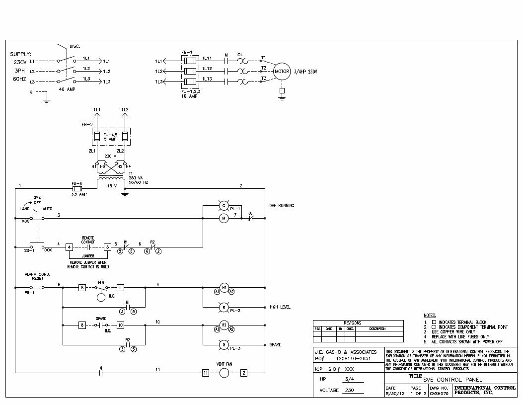


Remedial Action Report NYC BCP #12CBCP032R Devon/Staten Island, LLC
ROUX ASSOCIATES, INC. BAS1802.0001Y.107/CVRS
PLATES
1. Sub Slab Depressurization System