Embed Size (px)
Citation preview

KEWAUNEE NUCLEAR POWER PLANT
RELOAD SAFETY EVALUATION CYCLE 22
AUGUST 1996
WISCONSIN PUBLIC SERVICE CORPORATION WISCONSIN POWER & LIGHT COMPANY MADISON GAS & ELECTRIC COMPANY
:pDrADC i OO

RELOAD SAFETY EVALUATION
FOR
KEWAUNEE CYCLE 22
Prepared By:
Reviewed By:
Reviewed By:
Reviewed By:
Reviewed By:
Reviewed By:
Date: 7 as 96clear Fug Technician
A
uc ear Fuel Engineer
Nuclear Fuel Engineer
Nuclear F Analysis Sup isor
Director-Nuclear Licensing
Plant Operations Review Committee
Date: , 1 -
Date: _7 _-___o
Date:
Date: 9
Date: 96

1.0 SUMMARY .......
TABLE OF CONTENTS
......-.-.-. *....*.**......... ...
.. 1
CORE DESIGN............................
2.1 Core Description .......................
2.2 Operating Conditions and Limits ..............
2.3 Scram Worth Insertion Rate ...............
2.4 Shutdown Window .......................
2.5 Moderator Temperature Coefficient ............
3.0 ACCIDENT EVALUATIONS .................
3.1 Evaluation of Uncontrolled Rod Withdrawal from Sub(
3.2 Evaluation of Uncontrolled Rod Withdrawal at Power
3.3 Evaluation of Control Rod Misalignment ........
3.4 Evaluation of Dropped Rod ................
3.5 Evaluation of Uncontrolled Boron Dilution ......
3.6 Evaluation of Startup of an Inactive Loop .......
3.7 Evaluation of Feedwater System Malfunction ....
3.8
3.9
Evaluation
Evaluation
of Excessive Load
of Loss of Load
Increase
3.10 Evaluation of Loss of Normal Feedwater
3.11 Evaluation of Loss of Reactor Coolant Flow
3.12 Evaluation of Loss of Reactor Coolant Flow
3.13 Evaluation of Main Steam Line Break . .
3.14 Evaluation of Rod Ejection Accidents . ..
3.15 Evaluation of Fuel Handling Accident ..
3.16 Evaluation of Loss of Coolant Accident .
Due
Due
to F
to
3.17 Power Distribution Control Verification ..........
........ *.......
...........*.....
. . . . .............* * *
..... ..... . *. .
........ .......
. . . . . . . . . . . . . . . . .
.......- -.*........
eritical .
.................
.......... ....... .
..... .... .. ..
................
................
........ .... ..
.... .........
... ...........
......
ump Trip .........
Locked Rotor .. .. . .. .
.........
. . . . . . . . . . . . . . ..
....... ... . ..
......... . ...
-1i-
'3
6
11
13
15
17
20
22
24
26
28
30
32
S34
.36
38S
.39
.41
*43
.46
.51
.53
.. .............. 55

TABLE OF CONTENTS (CONTINUED)
10 TECHNICAL SPECIFICATIONS ... .................................. 57
5.0 STATISTICS UPDATE ................................. .......... 58
6.0 REFERENCES .......................................... ..... 61
- ii -

LIST OF TABLES
Cycle 22 Fuel Characteristics .......... ......
TABLE
.. 1
2.4.1
2.5.1
3.0.1
3.0.2
3.1.1
3.2.1
Control Rod Misalignment
Dropped Rod .....................................
Uncontrolled Boron Dilution ..........................
Startup of an Inactive Loop .............................
Feedwater System Malfunction..........................
Excessive Load Increase...............................
Loss of Load ....................................
Loss of Reactor Coolant Flow Due to Pump Trip .............
Loss of Reactor Coolant Flow Due to Locked Rotor . ...........
Main Steam Line Break ...............................
Rod Ejection Accident at HFP, BOC .................
Rod Ejection Accident at HZP, BOC .....................
Rod Ejection Accident at HFP, EOC .....................
Rod Ejection Accident at HZP, EOC ......................
Fuel Handling Accident ..............................
14
Peaking Factor Versus Shutdown Burnup ........
Moderator Temperature Coefficient ............
Kewaunee Nuclear Power Plant List of Safety Analyses
Safety Analyses Bounding Values .............
Uncontrolled Rod Withdrawal from Subcritical. ....
Uncontrolled Rod Withdrawal at Power .........
3.3.1
3.4.1
3.5.1
3.6.1
P.1
3.8.1
3.9.1
3.11.1
3.12.1
3.13.1
3.14.1
3.14.2
3.14.3
3.14.4
3.15.1
- Ill -
. . 52
.. . . . . . . .. . 14
..... . 16
... . 18
. . . . . . . . . . 19
. . . . . . . . 21
....... . 23
. . . . . . . . . . 25
.. 27
.. .. 29
. . . . ... . . . 31
........ . . 33
.--
. . . 35
. . . . . . . 37
.. .. 40
. . . . . . . . 42
..
. . . . . 4
... ....... 47
~47
..
. . 48
... ... .... 49
.. ...... . 50
. . . . .. . . . . .

LIST OF TABLES (CONTINUED)
TABLE
16.1 Loss of Coolant Accident ..... .................................. 54
5.0.1 Reliability Factors . .......................................... 59
5.0.2 -FQN Reliability Factors ....................................... 60
- iv -

LIST OF FIGURES
FIGURE
.1 Cycle 22 Loading Pattern ...........................................
2.2.1 Hot Channel Factor Normalized Operating Envelope ...................... 8
2.2.2 Control Bank Insertion Limits ...................................... 9
2.2.3 Target Band on Indicated Flux Difference as a Function
of Operating Power Level (Typical) ................................. 10
2.3.1 Scram Reactivity Insertion Rate .................... .............. 12
3.13.1 Variation of Reactivity with Core Temperature at 1000 PSIA for the End of Life Rodded Core with One Rod Stuck (Zero Power)..... . . . . ... 45
3.17.1 Maximum (FQ * P REL) vs Axial Core Height.............. . . . ... . . .. 56

1.0 SUMMARY
The Kewaunee Nuclear Power Plant is scheduled to shut down for the Cycle 21-22
refueling in September 1996. Startup of Cycle 22 is forecast for October 1996.
This report presents an evaluation of the Cycle 22 reload and demonstrates that the reload
will not adversely affect the safety of the plant. Those accidents which could potentially
be affected by the reload core design are reviewed.
Details of the calculational model used to generate physics parameters for this Reload
Safety Evaluation are described in References 1 and 11. Accident Evaluation
methodologies applied in this report are detailed in Reference 2. These reports have
been previously reviewed and approved by the NRC as shown in References 3 and 4.
The current physics model reliability factors are discussed in Section 5 of this report.
An evaluation, by accident, of the pertinent reactor parameters is performed by comparing
the reload analysis results with the current bounding safety analysis values. The
evaluations performed in this document employ the current Technical Specification
(Reference 5) limiting safety system settings and operating limits.
It is concluded that the Cycle 22 design is more conservative than results of previously
docketed accident analyses and implementation of this design will not introduce an
unreviewed safety question since:
-1-

1. the probability of occurrence or the consequences of an accident will not be increased,
2. the possibility for an accident or malfunction of a different type than any evaluated
previously in the safety analysis report will not be created and,
3. the margin of safety as defined in the basis for any technical specification will not be
reduced.
This conclusion is based on the assumption that there is adherence to plant operating
limitations and Technical Specifications (Reference 5) and Cycle 21 is shut down within
a ±500 MWD/MTU window of the nominal design End of Cycle (EOC) burnup of
16,500 MWD/MTU.
-2-

2.0 CORE DESIGN
2.1 Core Description
The reactor core consists of 121 fuel assemblies of 14 x 14 design. The core
loading pattern, assembly identification, control rod bank identification, instrument
thimble I.D., thermocouple I.D., and burnable poison rod configurations for
Cycle 22 are presented in Figure 2.1.1.
Twenty-four (24) new Siemens Power Corporation (SPC) standard assemblies
enriched to 4.1 w/o U235, twelve (12) SPC standard assemblies enriched to 4.5 w/o
U235, and eight (8) SPC "heavy" lead test assemblies enriched to 4.5 w/o U235 will
reside with 69 partially depleted SPC standard assemblies and 8 SPC "heavy" lead
test assemblies. The 16 SPC "heavy" lead test assemblies contain 405 KgU (per
assembly) versus 378 KgU in the SPC standard fuel design. Descriptions of the fuel
designs are provided in Ref. 6 for SPC standard and Ref. 13 for SPC heavy.
Table 2.1.1 displays the core breakdown by region, enrichment, and number of
previous duty cycles.
The Cycle 22 reload core.will employ 28 burnable poison rod assemblies (BPRAs)
containing 288 fresh and 64 partially depleted burnable poison rods. Each of the
8 "heavy" lead test assemblies will use 4 gadolinia poison rods at 4 wt % gadolinia.
Fuel assemblies with two or three previous duty cycles are loaded on the core
periphery flat region to lower power in that region and reduce reactor vessel fluence
(Reference 14) in the critical reactor vessel locations. Fuel duty during this fuel
cycle will assure peak fuel rod burnups less than the maximum burnup
recommended by the fuel vendors. The Cycle 22 fuel loading pattern is capable of
achieving a burnup of 16,395 MWD/MTU operating at full power, based on an end
of Cycle 21 burnup of 16,500 MWD/MTU.
-3-

Table 2.1.1
Cycle 22 Fuel Characteristics
( Bi-M denotes the SPC bi-metallic grid design.
() .HTP denotes the SPC High Thermal Performance grid design.
-4-
Number of
Initial Previous Region W/O Duty Fuel Rod Grid
Region Identifier U235 Cycles Assemblies Design Design
20 W 3.4 2 1 Standard Bi-M (0
22 Z 3.5 2 4 Standard Bi-M ()
22 Z 3.7 2 24 Standard Bi-M (
23 A 3.8 1 20 Standard Bi-M "
23 A 4.1 1 20 Standard Bi-M to
23 A 4.1 1 8 Heavy HTP a)
24 B 4.1 0 24 Standard HTP ()
24 B 4.5 0 12 Standard HTP a>
24 B 4.5/gad 0 8 Heavy HTP ()

Figure 2.1.1
1 2 3
R
LOOP 8
C z19
A90 869 0 AS o BB
2 2
E 875 2
228 A952 55 F 12N90
__ASS__ A BS A52
28 8s 8
H 12N491 27 6____ 0
083 231 13
A77 891
C01
K LOOP 8/9 17 3
L
M
4 5 6 7 8 9 10 11 12 13
215 A62 E17
AOS 079 A93 8e A98 878 A79
090 227 8714 A69 865 Z36 088 E22 'ISADI 12N89 NOB8 4GOD
S I_ 2 5 3
12
1
Z14 B & AS87 A0 471 8 225 894 AB4 N497 12NB96 4GAO14
23 3 S Ii L=I 1 12
871 202 863 ASS 870 112 872 2 881 1N98 a 121480 N
A82 880 86q As A5I 854 A73 881 A97 Zia 12N8n 12N79 12N87
A74 A7 ASO W25 AS As A72 ASS 885 ASS Bses
22 17 2
a55 203 864 a i 55 05 851 Z22 878 N99 12184 12N77 N94
331 2 __ - 1 122
1S 858 A78 ABS A75 868 Z28 892 A80 12140 N13 an
120 gao
ABS
nee9123
LOOP A
\ LOOP A
R00C = Pm( OLD BPA)
FIDI T/C l THIMBLE
CYCLE TWENTY-TWO
-5-
Bel 230 A ?67 873 ZSS 03 229 0[0 12092 12N5 ORDr
B96 A91 877 A85 SPa 4
981 882

2.2 Operating Conditions and Limits
Cycle 22 core design is based on the following operating conditions and limits.
2.2.1 Operating Conditions
- Power Rating (MWTH).........................1650 - System Pressure (PSIA).........................2250 - Core Average Moderator Temperature, HZP (oF) . . . . . . 547 - Core Average Moderator Temperature, HFP (oF) . . . . . . 562
2.2.2 Operating Limits
A. Nuclear peaking factor limits are as follows:
(i) FQ(Z) limits
a) For SPC standard fuel:
FQ(Z) (2.28/P) * K(Z) for P > 0.5 FQ(Z) < 4.56 * K(Z) for P < 0.5
K(Z) is the function given in Figure 2.2.1
Z is the core height
b) For SPC heavy fuel, the FQ(Z) limit is the SPC standard fuel limit less 5.3% (Ref. 13).
(ii) FAH limits
FAHN < 1.55 (1 + 0.2(1-P))
P is the fraction of full power at which the core is operating. Mixed core thermal hydraulic penalties have been evaluated (Ref. 15 and 16)'. The FAH limit applies to the HTP and the bi-metallic fuel assembly designs.
(iii) The SPC heavy fuel will not be limiting with respect to power distribution and LOCA analysis assumptions (Ref. 12).
B. The moderator temperature coefficient at operating conditions shall be less than +5.0 pcm/*F for 0% <- P :; 60%, shall be negative for P> 60%, and shall be less than -8.0 pcm/oF for 95% of the time at hot full power (Ref. 5).
-6-

C. With the most reactive rod stuck out of the core, the remaining control
rods shall be able to shut down the reactor by a sufficient reactivity
margin:
1.0% at Beginning of Cycle (BOC)
2.0% at End of Cycle (EOC)
D. The power dependent rod insertion limits (PDIL) are presented in
Figure 2.2.2. These limits are those currently specified in Reference 5.
E. The indicated axial flux difference shall be maintained within a + 5%
band about the target axial flux difference above 90 percent power.
Figure 2.2.3 shows the axial flux difference limits as a function of core
power. These limits are currently specified in Reference 5, which also
-provides limits on temporary operation allowed within the 3.10.b.11.a.
line envelope at power levels between 50 percent and 90 percent.
F. At refueling conditions a boron concentration of 2100 ppm will be
sufficient to maintain the reactor subcritical by 5 percent Ak/k with all
rods inserted and will maintain the core subcritical with all rods out.
-7-

FIGURE 2.2.1
1.2,
1.1
(6, 1.0) ..- -..... - ..- _.....
NORMALIZED ON
t- 2.28
(10.84, .938)
0.6 L
(12, .438) '
I I I I I
0 1 2 3 4 5 6 7-~ It 0 IV II
CORE HEIGHT (FT.)
FIGURE 2.2.1 - HOT CHANNEL FACTOR NORMALIZED OPERATING ENVELOPE
-8-
1.01.
E 0.9
0.8
0.7
r.J
I',I0a i v Iu I I 12c

FIGURE 2-2.2S
r I I I
I I L'I>
I- -
S -- .~ I I ~ I -. I
_____________ I I I
.L. i.. CONTRO -IN-SER-T-ION-LIMITS I I
I j.:**~ ~
SI.~l. ~. I I
,. I -7:7
I I '' 1-1 7
I:! I : I7I
' 77
So _- Y-4:: ..-
1001*
2.0 4 .... o o
-9-
0
I -
- - - - I

FIGURE 2.2.3
PERCENT OF RATED
THERMAL POWER
-r 100
'90
3.10.b.I I.o.LINE
60
50
40
30
-30 -20 -10 . 0 IO 20 30
INDICATED AXIAL FLUX DIFFERENCE
Target Band on Indicated Flux Difference
As a Function of Operating Power Level (Typical)
- 10 -
TARGET BAND

2.3 Scram Worth Insertion Rate
The most limiting scram curve is that curve which represents the slowest trip
reactivity insertion rate normalized to the minimum shutdown margin. The
Cycle 22 minimum shutdown margin is 2.14 percent at end of cycle hot full power
conditions. Figure 2.3.1 compares the Cycle 22 minimum scram insertion curve to
the current bounding safety analysis curve.
It is concluded that the minimum trip reactivity insertion rate.for Cycle 22 is
conservative with respect to the bounding value. Thus, for accidents in which
credit is taken for a reactor trip, the proposed reload core will not adversely affect
the results of the safety analysis due to trip reactivity assumptions.
- 11 -

Figure 2.3.1
SCRRM RERCTIVITY INSERTION RATE
1.00
TIME FROM ROD RE
- 12 -
o) CYCLE 22 RELOAD - CURRENT SAFETY ANALYSIS
3.00
2.50 z LUJ L)
LUJ
2.00
1.SO
LU
LUJ
z 0.50
0.00

2.4 Shutdown Window
An evaluation of the maximum full power equilibrium peaking factors versus
EOC 21 burnup is presented in Table 2.4.1. The values shown have conservatisms
applied in accordance with Reference 1.
It is concluded that if the shutdown of Cycle 21 occurs within the bumup window,
the Cycle 22 peaking factors will not be significantly affected and will not exceed
their limiting values.
- 13 -

Table 2.4.1
Peaking Factor Versus Shutdown Burnup
FAH FQ
._Cycle 22 Limit Cycle 22 Limit
EOC 21 - 500 MWD/MTU 1.53 1.55 2.17 2.28
EOC 21 Nominal 1.53 1.55 2.17 2.28
EOC 21 + 500 MWD/MTU 1.53 1.55 2.17 2.28
- 14 -

2.5 Moderator Temperature Coefficient
An evaluation of the Cycle 22 hot full power moderator temperature coefficient is
presented in Table 2.5.1. The calculated Cycle 22 value at Beginning of Cycle
(BOC) is compared to the MTC upper bound limit of -8.0 pcm/oF. Cycle 22 MTC
must be less than the upper bound limit for 95 % of the scheduled time at HFP due
to anticipated transient without scram (ATWS) concerns. Since MTC is less than
the limit at BOC, and becomes increasingly negative with cycle exposure, it will be
less than the upper bound limit for 95% of scheduled time at HFP. It is concluded
that the Cycle 22 MTC is conservative with respect to the bounding value.
Therefore, the Cycle 22 core will not adversely affect the results of the ATWS
safety analysis.
- 15 -

Table 2.5.1
Moderator Temperature Coefficient
- 16 -
Reload Safety Current Evaluation Value Safety Analysis Units
-9.6 -8.0 pcm/oFm

3.0 ACCIDENT EVALUATIONS
Table 3.0.1 presents the latest safety analyses performed. for the accidents which are
evaluated in Sections 3.1 through 3.16 of this report. The bounding values derived from
these analyses. are shown in Table 3.0.2 and will be applied in the Cycle 22 accident
evaluations.
- 17 -

Table 3.0.1
Kewaunee Nuclear Power Plant
List of Current Safety Analyses
Accident Current Safety Analysis
Uncontrolled RCCA Withdrawal From a Ref. 6 and 7 Subcritical Condition
Uncontrolled RCCA Withdrawal at Power Ref. 6 and 7
Control Rod Drop Ref. 6 and 7
RCC Assembly Misalignment Ref. 6 and 7
CVCS Malfunction Ref. 6 and 7
Startup of an Inactive RC Loop Ref. 6 and 7
Excessive Heat Removal Due to FW System Ref. 6 and 7 Malfunctions
Excessive Load Increase Incident Ref. 6 and 7
Loss of Reactor Coolant Flow Ref. 6 and 7
Due to Pump Trip Due to Underfrequency Trip
Locked Rotor Accident Ref. 6 and 7
Loss of External Electrical Load Ref. 6 and 7
Loss of Normal Feedwater Ref. 6 and 7
Fuel Handling Accidents Ref. 6 and 7
Rupture of a Steam Pipe Ref. 6 and 7
Rupture of CR Drive Mechanism Housing Ref. 6 and 7
Large Break LOCA Ref. 8 and 9
Small Break LOCA Ref. 10
- 18 -

Table 3.0.2
Safety Analyses Bounding Values
Parameter Lower Bound Upper Bound Units
Moderator Temp. Coefficient Most Negative -40.0 --- pcm/*Fm OP:560% --- +5.0 pcm/oFm
P>60% --- 0.0 pcm/*Fm 95% of time at HFP --- -8.0 pcm/oFm
URW from subcritical only --- +10.0 pcm/*Fm Dropped Rod EOL --- -17.0 pcm/oFm
Doppler Coefficient -2.32 -1.0 pcm/*Ff
Differential Boron Worth -11.2 -7.7 pcm/ppm
Delayed Neutron Fraction .00485 .00706 --
Prompt Neutron Lifetime 15 N/A psec
Shutdown Margin 1.0 (BOC) N/A % Ap 2.0 (EOC) N/A
Differential Rod Worth of 2 N/A 82 pcm/sec Banks Moving
Ejected Rod Cases
HFP, BOL Beff .0055 N/A --Rod Worth N/A .30 % Ap FQ N/A 5.03
HFP, EOL Beff .0050 N/A --Rod Worth N/A .42 % Ap FQ. N/A 5.1
HZP, BOL Beff .0055 N/A --Rod Worth N/A .91 % Ap FQ N/A 8.2
HZP, EOL Beff .0050 N/A --Rod Worth N/A .92 % Ap FQ N/A 13.0
- 19 -

3.1 Evaluation of Uncontrolled Rod Withdrawal from Subcritical
An uncontrolled addition of reactivity due to uncontrolled withdrawal of a Rod
Cluster Control Assembly (RCCA) results in a power excursion.
The most important parameters are the reactivity insertion rate and the doppler
coefficient. A maximum reactivity insertion rate produces a more severe transient
while a minimum (absolute value) doppler coefficient maximizes the nuclear power
peak. Of lesser concern are the moderator coefficient and delayed neutron fraction
which are chosen to maximize the peak heat flux.
Table 3.1.1 presents a comparison of Cycle 22 physics parameters to the current
safety analysis values for the Uncontrolled Rod Withdrawal from a Subcritical
Condition.
Since the pertinent parameters from the proposed Cycle 22 reload core are
conservatively bounded by those used in the current safety analysis, an uncontrolled
rod withdrawal from subcritical accident will be less severe than the transient in the
current safety analysis. Therefore, the implementation of the Cycle 22 reload core
design will not adversely affect the safe operation of the Kewaunee Plant.
- 20 -

Table 3.1.1
Uncontrolled Rod Withdrawal From Subcritical
- 21 -
Reload Safety Parameter Evaluation Current
Values Safety Analysis Units
A) Moderator Temp. +1.51 < 10.0 pcm/oFm Coefficient
B) Doppler Temp. -1.31 -1.0 pcm/oFf Coefficient
C) Differential Rod Worth .074 .116 $/sec of Two Moving Banks
D) Scram Worth vs. Time See Section 2.3
E) Delayed Neutron .00648 .00706 Fraction
F) Prompt Neutron 25 > 15 ktsec Lifetime

, i
3.2 Evaluation of Uncontrolled Rod Withdrawal at Power
An uncontrolled control rod bank withdrawal at power results in a gradual
increase in core power followed by an increase in core heat flux. The resulting
mismatch between core power and steam generator heat load results in an
increase in reactor coolant temperature and pressure.
The minimum absolute value of the doppler and moderator coefficients serves to
maximize peak neutron power, while the delayed neutron fraction is chosen to
maximize peak heat flux.
Table 3.2.1 presents a comparison of the Cycle 22 physics parameters to the
current safety analysis values for the Uncontrolled Rod Withdrawal at Power
Accident.
Since the pertinent parameters from the proposed Cycle 22 reload core are
conservatively bounded by those used in the current safety analysis, an
uncontrolled rod withdrawal at power accident will be less severe than the
transient in the current analysis. Therefore, the implementation of the Cycle 22
reload core design will not adversely affect the safe operation of the Kewaunee
Plant.
- 22 -

Table 3.2.1
Uncontrolled Rod Withdrawal at Power
- 23 -
Reload Safety Parameter Evaluation Current
Values Safety Analysis Units
A) Moderator Temp. -3.97 < 0.0 pcm/oFm Coefficient
B) Doppler Temp. -1.31 -1.0 pcm/*Ff Coefficient
C) Differential Rod Worth .074 < .116 $/sec
of Two Moving Banks
D) FAHN 1.53 1.55
E) Scram Worth vs. Time See Section 2.3
F) Delayed Neutron .00648 _ .00706 Fraction

3.3 Evaluation of Control Rod Misalignment
The static misalignment of an RCCA from its bank position does not cause a
system transient; however, it does cause an adverse power distribution which is
analyzed to show that core Departure from Nuclear Boiling Ratio (DNBR) limits
are not exceeded.
The limiting core parameter is the peak FAH in the worst case, misalignment of
Bank D fully inserted with one of its RCCAs fully withdrawn at full power.
Table 3.3.1 presents a comparison of the Cycle 22 FAHN versus the current safety
analysis FAH limit for the Control Rod Misalignment Accident.
Since the pertinent parameter from the proposed Cycle 22 reload core is
conservatively bounded by that used in the current safety analysis, a control rod
misalignment accident will be less severe than the transient in the current analysis.
Therefore, the implementation of the Cycle 22 reload core design will not
adversely affect the safe operation of the Kewaunee Plant.
- 24 -
.4
Table 3.3.1
Control Rod Misalignment
Reload Safety Current Parameter Evaluation Value Safety Analysis
A) FAHN 2.029 ; 2.03
- 25 -

3.4 Evaluation of Dropped Rod
The release of a full length control rod or control rod bank by the gripper coils
while the reactor is at power causes the reactor to become subcritical and produces
a mismatch between core power and turbine demand. The dropping of any control
rod bank will produce a negative neutron flux rate trip with no resulting decrease
in thermal margins. Dropping of a single RCCA or several RCCA's from the
same bank may or may not result in a negative rate trip, and therefore the radial
power distribution must be considered.
Table 3.4.1 presents a comparison of the Cycle 22 physics parameters to the
current safety analysis values for the Dropped Rod Accident.
Since the pertinent parameters from the proposed Cycle 22 reload core are
conservatively bounded by that used in the current safety analysis, a dropped rod
accident will be less severe than the transient in the current analysis. Therefore,
the implementation of the Cycle 22 reload core design will not adversely affect the
safe operation of the Kewaunee Plant.
- 26 -

Table 3.4.1
Dropped Rod
- 27 -
Reload Safety Current Parameter Evaluation Value Safety Analysis Units
A) FAHN 1.53 _ 1.55
B) Doppler Temp. -1.31 -1.0 pcm/*Ff Coefficient
C) Delayed Neutron .00648 .00706Fraction
D) Excore Tilt .86. > .80 --(Control)
E) Full Power 386 < 400 pcm Insertion Limit Worth (BOL)
F) Full Power 441 450 pcm Insertion Limit Worth (EOL)
G) Moderator -3.97 0.0 pcm/oFm Temperature Coefficient (BOL)
H) Moderator -17.0 pcm/0 Fm Temperature Coefficient (EOL)

3.5 Evaluation of Uncontrolled Boron Dilution
The malfunction of the Chemical and Volume Control System (CVCS) is assumed
to deliver unborated water to the Reactor Coolant System (RCS).
Although the boron dilution rate and shutdown margin are the key parameters in
this event, additional parameters are evaluated for the manual reactor control case.
In this case core thermal limits are approached and the transient is terminated by a
reactor trip on over-temperature AT.
Table 3.5.1 presents a comparison of Cycle 22 physics analysis results to the
current safety analysis values for the Uncontrolled Boron Dilution Accident for
refueling and full power core conditions.
Since the pertinent parameters from the proposed Cycle 22 reload core are
conservatively bounded by those used in the current safety analysis, an
uncontrolled boron dilution accident will be less severe than the transient in the
current analysis. Therefore, the implementation of the Cycle 22 reload core
design will not adversely affect the safe operation of the Kewaunee Plant.
- 28 -

Table 3.5.1
Uncontrolled Boron Dilution
- 29 -
Reload Safety Current
Evaluation Safety Parameter Values Analysis Units
i) Refueling Conditions
A) Shutdown Margin 5.9 5.0 %
ii) At-Power Conditions
A) Moderator Temp. Coefficient -3.79 5 0.0 pcm/oFm
B) Doppler Temp. Coefficient -1.31 -1.0 pcm/*Ff
C) Reactivity Insertion Rate by Boron .0018 .0023 $/sec
D) Shutdown Margin 2.14 1.0 %
E) FAHN 1.53 _ 1.55
F) Delayed Neutron Fraction .00648 .00706

3.6 Evaluation of Startup of an Inactive Loop
The startup of an idle reactor coolant pump in an operating plant would result in
the injection of cold water (from the idle loop hot leg) into the core which causes a
rapid reactivity insertion and subsequent core power increase.
The moderator temperature coefficient is chosen to maximize the reactivity effect
of the cold water injection. Doppler temperature coefficient is chosen
conservatively low (absolute value) to maximize the nuclear power rise. The
power distribution (FAH) is used to evaluate the core thermal limit acceptability.
Table 3.6.1 presents a comparison of the Cycle 22 physics calculation results to
the current safety analysis values for the Startup of an Inactive Loop Accident.
Since the pertinent parameters from the proposed Cycle 22 reload core are
conservatively bounded by those used in the current safety analysis, the startup of
an inactive loop accident will be less severe than the transient in the current
analysis. Therefore, the implementation of the Cycle 22 reload core design will
not adversely affect the safe operation of the Kewaunee Plant.
- 30 -
I

Table 3.6.1
Startup of an Inactive Loop
Reload Safety Current Parameter Evaluation Values Safety Analysis Units
A) Moderator Temp. -35.3 -40.0 pcm/*Fm Coefficient
B) Doppler Coefficient -1.87 -1.0 pcm/*Ff
C) FAHN 1.53 _1.55
- 31 -

3.7 Evaluation of Feedwater System Malfunction
The malfunction of the feedwater system such that the feedwater temperature is
decreased or the flow is increased causes a decrease in the RCS temperature and
an attendant increase in core power level due to negative reactivity coefficients
and/or control system action.
Minimum and maximum moderator coefficients are evaluated to simulate both
BOC and EOC conditions. The doppler reactivity coefficient is chosen to
maximize the nuclear power peak.
A comparison of Cycle 22 physics calculation results to the current safety analysis
values for the Feedwater System Malfunction Accident is presented in Table 3.7.1.
Since the pertinent parameters from the proposed Cycle 22 reload core are
conservatively bounded by those used in the current safety analysis, a feedwater
system malfunction will be less severe than the transient in the current analysis.
Therefore, the implementation of the Cycle 22 reload core design will not
adversely affect the safe operation of the Kewaunee Plant.
- 32 -

Table 3.7.1
Feedwater System Malfunction
Reload Safety Current
Evaluation Safety Parameter Values Analysis Units
i) Beginning of Cycle
A) Moderator Temp. Coefficient -3.97 0.0 pcm/*Fm
B) Doppler Temp. Coefficient -1.31 -1.0 pcm/oFf
ii) End of Cycle
A) Moderator Temp. Coefficient -29.80 -40.0 pcm/oFm
B) Doppler Temp. Coefficient -1.31 -1.0 pcm/*Ff
iii) Beginning and End of Cycle
C) FAHN 1.53I. ________________________________________
1.55
- 33 -

3.8 Evaluation of Excessive Load Increase
An excessive load increase causes a rapid increase in steam generator steam flow.
The resulting mismatch between core heat generation and secondary side load
demand results in a decrease in reactor coolant temperature which causes a core
power increase due to negative moderator feedback and/or control system action.
This event results in a similar transient as that described for the feedwater system
malfunction and is therefore sensitive to the same parameters:
Table 3.8.1. presents a comparison of Cycle 22 physics results to the current safety
analysis values for the Excessive Load Increase Accident.
Since the pertinent parameters from the proposed Cycle 22 reload core are
conservatively bounded by those used in the current safety analysis, an excessive
load increase accident will be less severe than the transient in the current analysis.
Therefore, the implementation of the Cycle 22 reload core design will not
adversely affect the safe operation of the Kewaunee Plant.
- 34 -

Table 3.8.1
Excessive Load Increase
Reload Safety Current
Evaluation Safety Parameter Values Analysis Units
i) Beginning of Cycle
A) Moderator Temp. Coefficient -3.97 0.0 pcm/*Fm
B) Doppler Temp. Coefficient -1.31 -1.0 pcm/*Ff
ii) End of Cycle
A) Moderator Temp. Coefficient -29.80 -40.0 pcm/oFm
B) Doppler Temp. Coefficient -1.31 -1.0 pcm/oFf
iii) Beginning and End of Cycle
C) FAHN 1.53 1.55.1 _____________________ .P.......L ____________________
(
- 35 -
I

3.9 Evaluation of Loss of Load
A loss of load is encountered through a turbine trip or complete loss of external
electric load. To provide a conservative assessment of this event, no credit is
taken for direct turbine/reactor trip, steam bypass, or pressurizer pressure control,
and the result is a rapid rise in steam generator shell side pressure and reactor
coolant system temperature.
Minimum and maximum moderator coefficients are evaluated to simulate both
BOC and EOC conditions., The doppler reactivity coefficient is chosen to
maximize the nuclear power and heat flux transient. The power distribution
(FAH) and scram reactivity are evaluated to ensure thermal margins are
maintained by the reactor protection system.
A comparison of Cycle 22 physics parameters to the current safety analysis values
for the Loss of Load Accident is presented in Table 3.9. 1.
Since the pertinent parameters from the proposed Cycle 22 reload core are
conservatively bounded by those used in the current safety analysis, a loss of load
accident will be-less severe than the transient in the current analysis. Therefore,
the implementation of the Cycle 22 reload core design will not adversely affect the
safe operation of the Kewaunee Plant.
- 36 -

Table 3.9.1
Loss of Load
- 37 -
Reload Safety Current
Evaluation Safety Parameter Values Analysis Units
i) Beginning of Cycle
A) Moderator Temp. Coefficient -3.97 < 0.0 pcm/*Fm
B) Doppler Temp. Coefficient -1.61 -2.32 pcm/oFf
ii) End of Cycle
A) Moderator Temp. Coefficient -29.80 t -40.0 pcm/*Fm
B) Doppler Temp. Coefficient -1.60 -2.32 pcm/oFf
iii) Beginning and End of Cycle
C) FAHN 1.53 1.55 --
D) Scram Worth Versus Time See Section 2.3

3.10 Evaluation of Loss of Normal Feedwater
A complete loss of normal feedwater is assumed to occur due to pump failures or
valve malfunctions. An additional conservatism is applied by assuming the reactor
coolant pumps are tripped, further degrading the heat transfer capability of the
steam generators. When analyzed in this manner, the accident corresponds to a
loss of offsite power.
The short term effects of the transient are covered by the Loss of Flow Evaluation
(Sec. 3.11), while the long term effects, driven by decay heat, and assuming
auxiliary feedwater additions and natural circulation RCS flow, have been shown
not to produce any adverse core conditions.
The Loss of Feedwater Transient is not sensitive to core physics parameters and
therefore no comparisons will be made for the Reload Safety Evaluation.
- 38 -

3.11 Evaluation of Loss of Reactor Coolant Flow Due to Pump Trip
The simultaneous loss of power or frequency decay in the electrical buses feeding
the reactor coolant pumps results in a loss of driving head and a flow coast down.
The effect of reduced coolant flow is a rapid increase in core coolant temperature.
The reactor is tripped by one of several diverse and redundant signals before
thermal hydraulic conditions approach those which could result in fuel damage.
The doppler temperature coefficient is compared to the most negative value since
this results in the slowest neutron power decay after trip. The moderator
temperature coefficient is least negative to cause a larger power rise prior to the
trip. Trip reactivity and FAH are evaluated to ensure core thermal margin.
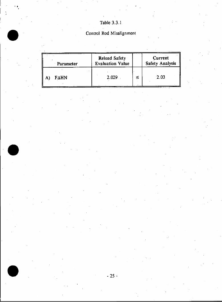
Table 3. 11. 1 presents a comparison of Cycle 22 calculated physics parameters to
the current safety analysis values for the Loss of Reactor Coolant Flow Due to
Pump Trip Accident.
Since the pertinent parameters from the proposed Cycle 22 reload core are
conservatively bounded by those used in the current safety analysis, a loss.of
reactor coolant flow due to pump trip accident will be less severe than the transient
in the current analysis. Therefore, the implementation of the Cycle 22 reload core
design will not adversely affect the safe operation of the Kewaunee Plant.
- 39 -
Table 3.11.1
Loss of Reactor Coolant Flow Due to Pump Trip
- 40 -
Reload Safety Current
Evaluation Safety Parameter Values Analysis Units
A) Moderator Temp. Coefficient -3.97 0.0 pcm/*Fm
B) Doppler Temp. Coefficient -1.60 -2.32 pcm/*Ff
C) FAHN 1.53 1.55 T D) Scram Worth Versus Time See Section 2.3
E) Fuel Temperature 2045 5 2100 1 F

3.12 Evaluation of Loss of Reactor Coolant Flow Due to Locked Rotor
This accident is an instantaneous seizure of the rotor of a single reactor coolant
pump resulting in a rapid flow reduction in the affected loop. The sudden
decrease in flow results in DNB in some fuel rods.
The minimum (absolute value) moderator temperature coefficient results in the
least reduction of core power during the initial transient. The large negative
doppler temperature coefficient causes a slower neutron flux decay following the
trip as does the large delayed neutron fraction.
Table 3.12.1 presents a comparison of Cycle 22 physics parameters to the current
safety analysis values for the Locked Rotor Accident.
Since the pertinent parameters from the proposed Cycle 22 reload core are
conservatively bounded by those used in the current safety analysis, a locked rotor
accident will be less severe than the transient in the current analysis. Therefore,
the implementation of the Cycle 22 reload core design will not adversely affect the
safe operation of the Kewaunee Plant.
- 41 -
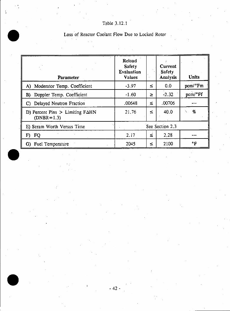
Table 3.12.1
Loss of Reactor Coolant Flow Due. to Locked Rotor
- 42 -
Reload Safety Current
Evaluation Safety Parameter Values Analysis Units
A) Moderator Temp. Coefficient -3.97 2 0.0 pcm/*Fm
B). Doppler Temp. Coefficient -1.60 -2.32 pcm/*Ff
C) Delayed Neutron Fraction .00648 5 .00706 --
D) Percent Pins > Limiting FAHN 21.76 5 40.0 % (DNBR= 1.3)
E) Scram Worth Versus Time See Section 2.3
F) FQ 2.17 2.28 --
G) Fuel Temperature 2045 5 2100 OF

3.13 Evaluation of Main Steam Line Break
The break of a main steam line inside containment at the exit of the steam
generator causes an uncontrolled steam release and a reduction in primary system
temperature and pressure. The negative moderator coefficient produces a positive
reactivity insertion and a potential return to criticality after the trip. The doppler
coefficient is chosen to maximize the power increase.
Shutdown margin at the initiation of the cooldown and reactivity insertion and
peak rod power (FAH) during the cooldown are evaluated for this event. The
ability of the safety injection system to insert negative reactivity and reduce power
is minimized by using the least negative boron worth coefficient.
Table 3.13.1 presents a comparison of Cycle 22 calculated physics parameters to
the current safety analysis values for the main steam line break accident. Figure
3.13.1 compares core Keff during the cooldown to the current bounding safety
analysis curve.
Since the pertinent parameters from the proposed Cycle 22 reload core are
conservatively bounded by those used in the current safety analysis, a main steam
line break accident will be less severe than the transient in the current analysis.
Therefore, the implementation of the Cycle 22 reload core design will not
adversely affect the safe operation of the Kewaunee Plant.
- 43 -

Table 3.13.1
Main Steam Line Break
- 44 -
Reload Safety Current
Evaluation Safety Parameter Values Analysis Units
A) Shutdown Margin 2.14 2.00 %&p
B) FAH 4.32 4.4 --
C) Doppler Temp. Coefficient -1.31 -1.0 pcm/*Ff
D) Boron Worth Coefficient -7.72 < -7.7 pcm/ppm
I

Figure 3.13.1
VRRIRTION OF PT 1000 CORE W
O
LuJ
RERCTIVITY, WITH CORE TEMPERATURE
PSIR FOR THE END OF LIFE RODDED
ITH ONE ROD STUCK (ZERO POWER)
.00
CORE RVERRGE TEMPERRTURE (DEG F)
- 45 -
I I
3.14 Evaluation of Rod Ejection Accidents
The ejected rod accident is defined as a failure of a control rod drive pressure
housing followed by the ejection of a RCCA by the reactor coolant system
pressure.
Tables 3.14.1 through 3.14.4 present the comparison of Cycle 22 calculated
physics parameters to the current safety analysis values for the Rod Ejection
Accident at zero and full power, BOC and EOC core conditions.
Since the pertinent parameters from the proposed Cycle 22 reload core are
conservatively bounded by those used in the current safety analysis, a rod ejection
accident will be less severe than the transient in the current analysis. Therefore,
the implementation of the Cycle 22 reload core design will not adversely affect the
safe operation of the Kewaunee Plant.
- 46 -

Table 3.14.1
Rod Ejection Accident at
HFP, BOC
- 47 -
Reload Safety Current
Evaluation Safety Parameter Values Analysis Units
A) Moderator Temp. Coefficient -3.97 0.0 pcm/*Fm
B) Delayed Neutron Fraction .00610 .00550 --
C) Ejected Rod Worth .09 5 0.30 %&p
D) Doppler Temp. Coefficient -1.31 < -1.0 pcm/*Ff
E) Prompt Neutron Lifetime 25 ? 15 Asec
F) FQN 2.50 5.03_
G) Scram Worth Versus Time See Section 2.3

, .
Table 3.14.2
Rod Ejection Accident at
HZP, BOC
m )SrauothVrusTm
Reload Safety Current
Evaluation Safety Parameter Values Analysis Units
A) Moderator Temp. Coefficient +1.51 5 5.0 pcm/*Fm
B) Delayed Neutron Fraction .00610 t .00550 --
C) Ejected Rod Worth 0.63 - 0.91 %Ap
D) Doppler Temp. Coefficient -2.07 < -1.0 pcm/*Ff
E) Prompt Neutron Lifetime 25 15 14sec
F) FQN 5.3 _ 8.2 ---
G~ Scram Worth Versus Time See Section 2.3
- 48 -

I.
Table 3.14.3
Rod Ejection Accident at
HFP, EOC
- 49 -
Reload Safety Current
Evaluation Safety Parameter Values Analysis Units
A) Moderator Temp. Coefficient -20.99 5 0.0 pcm/*Fm
B) Delayed Neutron Fraction .00521 .00500 --
C) Ejected Rod Worth 0.12 0.42 %Ap
D) Doppler Temp. Coefficient -1.31 -1.0 pcm/*Ff
E) Prompt Neutron Lifetime 28 15 psec
F) FQN 2.82 5.1
G) Scram Worth Versus Time See Section 2.3

Table 3.14.4
Rod Ejection Accident at
HZP, EOC
- 50 -
Reload Safety Current
Evaluation Safety Parameter Values Analysis Units
A) Moderator Temp. Coefficient -7.0 t 5.0 pcm/*Fm
B) Delayed Neutron Fraction .00521 .00500 --
C) Ejected Rod Worth 0.69 < 0.92 %Ap
D) Doppler Temp. Coefficient -2.54 < -1.0 pcm/*Ff
E) Prompt Neutron Lifetime 28 15 Asec
F) FQN 7.52 13.0 --
G) Scram Worth Versus Time See Section 2.3

3.15 Evaluation of Fuel Handling Accident
This accident is the sudden release of the gaseous fission products held within the
fuel cladding of one fuel assembly. The fraction of fission gas released is based
on a conservative assumption of high power in the fuel rods during their last six
weeks of operation.
The maximum FQ expected during this period is evaluated within the restrictions
of the power distribution control procedures.
Table 3.15.1 presents a comparison of the maximum Cycle 22 FQN calculated
during the last 2.0 GWD/MTU of the cycle to the current safety analysis FQN
limit for the Fuel Handling Accident.
Since the pertinent parameter from the proposed Cycle 22 reload core is
conservatively bounded by that used in the current safety analysis, a fuel handling
accident will be less severe than the accident in the current analysis. Therefore,
the implementation of the Cycle 22 reload core design will not adversely affect the
safe operation of the Kewaunee Plant.
- 51 -

Table 3.15.1
Fuel Handling Accident
- 52 -
Reload Safety Current
Evaluation Safety Parameter Values Analysis
A) FQN 199 ; 2.53
IR

~1
3.16 Evaluation of Loss of.Coolant Accident
The Loss of Coolant Accident (LOCA) is defined as the rupture of the reactor
coolant system piping or any line connected to the system, up to and including a
double-ended guillotine rupture of the largest pipe.
The principal parameters which affect the results of LOCA analysis are the fuel
stored energy, fuel rod internal pressures, and decay heat. These parameters are
affected by the reload design dependent parameters shown in Table 3.16.1.
The initial conditions for the LOCA analyses are assured through limits on fuel
design, fuel rod burnup, and power distribution control strategies.
Table 3.16.1 presents the comparison of Cycle 22 physics calculation results to the
current safety analysis values for the Loss of Coolant .Accident.
Since the pertinent parameters from the proposed Cycle 22 reload core are
conservatively bounded by those used in the current safety analysis, a loss of
coolant accident will be less severe than the transient in the current analysis.
Therefore, the implementation of the Cycle 22 reload core design will not
adversely affect the safe operation of the Kewaunee Plant.
- 53 -

Table 3.16.1
Loss of Coolant Accident
- 54 -
Reload Safety Current
Evaluation Safety Parameter Values Analysis
A) Scram Worth Versus Time See Section 2.3
B) FQ See Section 3.17
C) FAH 1.53 5 1.55

3.17 Power Distribution Control Verification
The total peaking factor FQT relates the maximum local power density to the core
average power density. The FQT is determined by both the radial and axial power
distributions. The radial power distribution is relatively fixed by the core loading
pattern design. The axial power distribution is controlled by the Technical
Specifications (Ref. 5).
FQT(Z) are determined by calculations performed at full power, equilibrium core
conditions, at exposures ranging from BOC to EOC. Conservative factors which
account for potential power distribution variations allowed by the power
distribution control specifications, manufacturing tolerances, and measurement
uncertainties are applied to the calculated FQT(Z).
Figure 3.17.1 compares the calculated FQT(Z), including uncertainty factors, to
the FQT(Z) limits. These results demonstrate that the power distributions
expected during Cycle 22 operation will not preclude full power operation under
the power distribution control specifications currently applied (Reference 5).
- 55 -
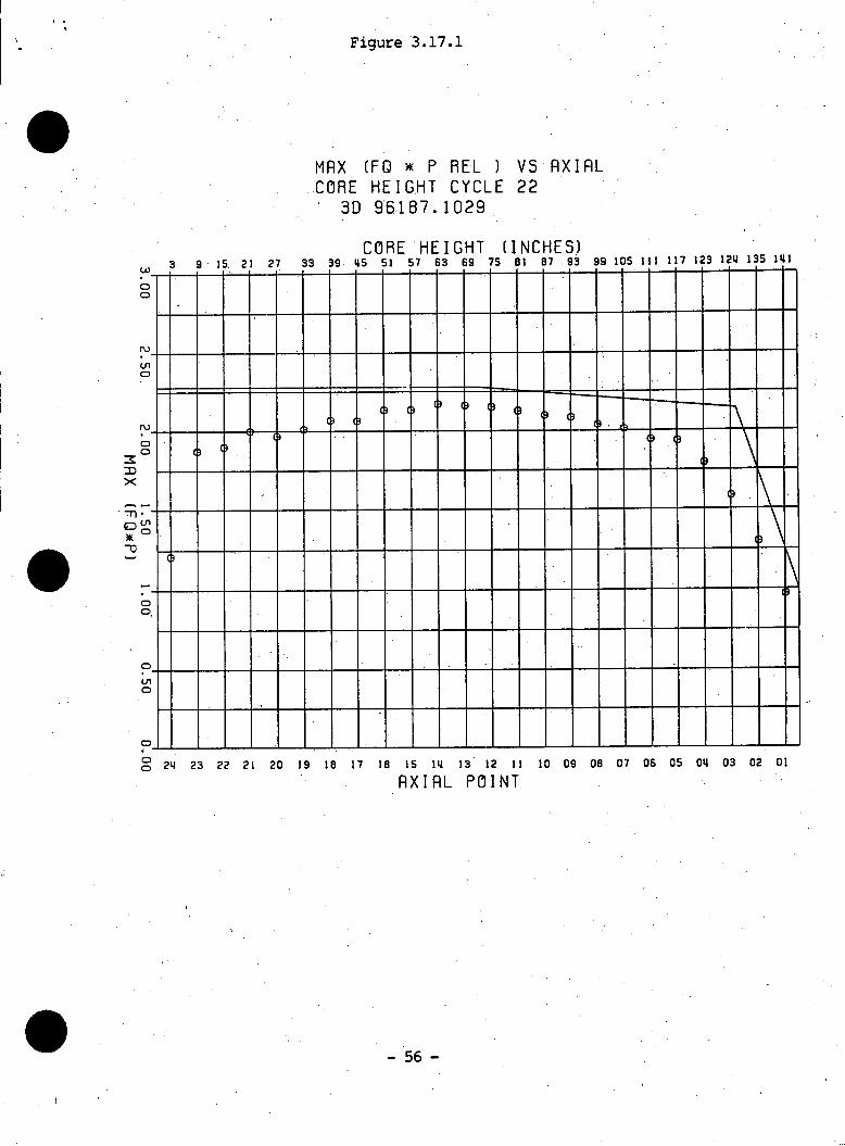
Figure 3.17.1
MAX (FQ ) P REL ) VS AXIAL CORE HEIGHT CYCLE 22
3D 96187.1029
CORE HEIGHT (INCHES)3 9 15 21 27 33 39 45 51 57 63 69 75 81 87 93 99 105 11 17 123 124 13 141
CD
0
23 22 21 20 19 18 17 16 15 14 13 12 11 10 09 08 07 06 05
AXIAL POINT04 03 02 01
- 56 -
)1
0 M

4.0 TECHNICAL SPECIFICATIONS
No Technical Specification change was required as a result of this reload.
- 57 -

5.0 STATISTICS UPDATE
Measurements and calculations of Cycles 18, 19, and 20 are incorporated into the
FQN and FAH statistics data base. The moderator temperature coefficient
statistics data base includes results from Cycles 13 through 20. The reliability
and bias factors used for the Cycle 22 Reload Safety Evaluations are presented
in Tables 5.0.1 and 5.0.2.
- 58 -

Table 5.0.1
Reliability Factors
- 59 -
Parameter Reliability Factor Bias
FQN See Table 5.0.2
FAH 4.08% 0
Rod Worth 10.0% 0
Moderator Temperature 2.7 pcm/oF 3.1 pcm/*F Coefficient
Doppler Coefficient 10.0% 0
Boron Worth 5.0% 0
Delayed Neutron Parameters 3.0% 0

Table 5.0.2
FQN Reliability Factors
Core Level uNode RF (%)
1 (Bottom) .0585 10.23
2 .0476 8.46
3 .0186 4.20
4 .0211 4.51
5 .0237 4.85
6 .0189 4.23
7 .0206 4.45
8 .0187 4.21
9 .0196 4.32
10 .0167 3.98
11 .0163 3.93
12 .0169 4.00.
13 .0161 3.91
14 .0163 3.93
15 .0172 4.03
16 .0167 3.98
17 .0210 4.50
18 .0184 4.17
19 .0263 5.21
20 .0248 5.00
21 .0452 8.07
22 .0357 6.59
23 .0806 13.91
24 (Top) .0752 13.00
- 60 -
6.0 REFERENCES
1. Wisconsin Public Service Corporation, Kewaunee Nuclear Power Plant,
topical report entitled, "Qualification of Reactor Physics Methods for
Application to Kewaunee," dated September 29, 1978.
2. Wisconsin Public Service Corporation, Kewaunee Nuclear Power Plant,
topical report WPSRSEM-NP-A entitled, "Reload Safety Evaluation Methods
for Application to Kewaunee," Revision 2, dated October 1988.
3. Safety Evaluation Report by the Office of Nuclear Reactor Regulation:
"Qualification of Reactor Physics Methods for Application to Kewaunee,"
October 22, 1979.
4. Safety Evaluation Report by the Office of Nuclear Reactor Regulation:
"Reload Safety Evaluation Methods for Application to Kewaunee," April
1988.
5. Wisconsin Public Service Corporation Technical Specifications for the
Kewaunee Nuclear Power Plant. Docket Number 50-305, Amendment
No. 23, dated January 3, 1996.
- 61 -
I

6. Wisconsin Public Service Corporation, Kewaunee Nuclear Power Plant,
Updated Safety Analysis Report.
7. ESR 95-023, "Safety Analysis for 25% Steam Generator Tube Plugging,"
May 10, 1995.
8. "Kewaunee High Burnup Safety Analysis: Limiting Break LOCA &
Radiological Consequences," XN-NF-84-31, Revision 1, Exxon Nuclear
Company, Inc., October 1, 1984.
9. EMF 95-075(P), "Kewaunee Large Break LOCA/ECCS Analysis with 25%
Steam Generator Tube Plugging," April 1995.
10. WCAP 14103, "Kewaunee Small Break LOCA Analysis Report,',' June 1994.
11. Reload Safety Evaluation (Appendix A) for Kewaunee Nuclear Power Plant
Cycle 17, February 1991.
12. WPS letter from C. R. Steinhardt to U.S. Nuclear Regulatory Commission,
Docket 50-305, dated June 19, 1991, "Core Reloads of Advanced Design
Fuel Assemblies."
- 62 -

13. EMF-94-207, Rev. 2, dated June 1996, "Kewaunee HTP Lead Assembly.
Compatibility Report."
14. NRC Letter 89-061, from C. R. Steinhardt to U.S. NRC Document Control
Desk, May 12, 1989.
15. EMF 96-038, May 1996, "Kewaunee Mixed Core Thermal Hydraulic
Compatibility Report."
16. Letter from J. T. Holly to Cycle 22 Reload Safety Evaluation File,
"Cycle 22 Mixed Core Thermal Hydraulic Evaluation," dated July 16, 1996.
- 63 -


![Capítulo I Estándares eLearning Introducción a RELOAD · [ reload ] Capítulo I Estándares eLearning Introducción a RELOAD _____ Juan Egea García – www ... (Figura obtenida](https://img.dokumen.tips/doc/110x75/5b1bd2f27f8b9a23258f06c5/capitulo-i-estandares-elearning-introduccion-a-reload-capitulo-i-estandares.jpg)