Embed Size (px)
Citation preview

Reinforced Concrete Design by ELPLA
-41-
Example 1: Design of a square footing for different codes
1 Description of the problem
An example is carried out to design a spread footing according to EC 2, DIN 1045, ACI and
ECP.
A square footing of 0.5 [m] thickness with dimensions of 2.6 [m] × 2.6 [m] is chosen. The
footing is supported to a column of 0.4 [m] × 0.4 [m], reinforced by 8 Φ 16 and carries a load of
1276 [kN]. The footing rests on Winkler springs that have modulus of subgrade reaction of ks =
40 000 [kN/ m3]. A thin plain concrete of thickness 0.15 [m] is chosen under the footing and is
not considered in any calculations.
2 Footing material and section
The footing material and section are supposed to have the following parameters:
2.1 Material properties
Concrete grade according to ECP
Steel grade according to ECP
Concrete cube strength
Concrete cylinder strength
Compressive stress of concrete
Tensile stress of steel
Reinforcement yield strength
Young's modulus of concrete
Poisson's ratio of concrete
Unit weight of concrete
C 250
S 36/52
fcu = 250
fc = 0.8 fcu
fc = 95
fs = 2000
fy = 3600
Eb = 3 × 10⁷
νb = 0.15
γb = 0.0
[kg/ cm2]
[-]
[kg/ cm2]
[kg/ cm2]
[kg/ cm2]
[kN/ m2]
[-]
[kN/ m3]
= 25
= 20
= 9.5
= 200
= 360
= 30000
[MN/ m2]
[MN/ m2]
[MN/ m2]
[MN/ m2]
[MN/ m2]
[MN/ m2]
Unit weight of concrete is chosen γb = 0.0 to neglect the own weight of the footing.
2.2 Section properties
Width of the section to be designed
Section thickness
Concrete cover + 1/2 bar diameter
Effective depth of the section
Steel bar diameter
b = 1.0
t = 0.50
c = 5
d = t - c = 0.45
Φ = 18
[m]
[m]
[cm]
[m]
[mm]

Reinforced Concrete Design by ELPLA
-42-
3 Analysis of the footing
To carry out the analysis, the footing is subdivided into 64 square elements. Each has
dimensions of 0.325 [m] × 0.325 [m] as shown in Figure 13.
If a point load represents the column load on the mesh of finite elements, the moment under the
column will be higher than the real moment. In addition, to take effect of the load distribution
through the footing thickness, the column load is distributed outward at 45 [] from the column
until reaching the center line of the footing. Therefore, using the option "Distribute column load"
when defying load data in ELPLA, distributes the column load automatically at center line of the
footing on an area of (a + d)2 as shown in Figure 13.
Figure 14 shows the calculated contact pressure q [kN/ m2], while Figure 15 shows the bending
moment mx [kN.m/ m] at the critical section I-I of the footing.
For the different codes, the footing is designed to resist the bending moment and punching shear.
Then, the required reinforcement is obtained. Finally, a comparison among the results of the four
codes is presented.

Reinforced Concrete Design by ELPLA
-43-
Figure 13 Footing dimensions and distribution of column load through the footing
P = 1276 [kN]
b) Section I-I
0.325×8 = 2.60 [m]
pw = 1575 [kN/ m2]
0.90 [m]
a) Plan
I I
a = b = 0.4
Centerline t = 0.5 [m]
0.9
0 [
m]
0.3
25×
8 =
2.6
0 [
m]
pw = 1575 [kN/ m2]

Reinforced Concrete Design by ELPLA
-44-
Figure 14 Contact pressure q [kN/ m2] at section I-I
Figure 15 Moment mx [kN.m/ m] at section I-I
x [m]
160
120
40
2.0 1.0 0
0.0
153
80
Mom
ent
mx
[kN
.m/
m]
x [m]
200
250
150
50
2.0 1.0 0
0.0
195
100
Asx Asy
2.60 [m] Section I-I
P = 1276 [m]
Conta
ct p
ress
ure
q [
kN
/m2]
d =
0.4
5 [
m]
t =
0.5
[m
]

Reinforced Concrete Design by ELPLA
-45-
4 Design for EC 2
4.1 Design for flexure moment
Material
Concrete grade C 250 (ECP) = C 20/25 (EC 2)
Steel grade S 36/52 (ECP) = BSt 360 (EC 2)
Characteristic compressive cylinder strength of concrete fck = 20 [MN/ m2]
Characteristic tensile yield strength of reinforcement fyk = fy = 360 [MN/ m2]
Partial safety factor for concrete strength γc = 1.5
Design concrete compressive strength fcd = fck/γc = 20/1.5 = 13.33 [MN/ m2]
Partial safety factor for steel strength γs = 1.15
Design tensile yield strength of reinforcing steel fyd = fyk/γs = 360/1.15 = 313 [MN/ m2]
Factored moment
Moment per meter at critical section obtained from analysis M = 153 [kN.m] = 0.153 [MN.m]
Total load factor for both dead and live loads γ = 1.5
Factored moment Msd = γM = 1.5 × 0.153 = 0.2295 [MN.m]
Geometry
Effective depth of the section d = 0.45 [m]
Width of the section to be designed b = 1.0 [m]
Check for section capacity
The limiting value of the ratio x/ d is ξlim = 0.45 for fck ≤ 35 [MN/ m2].
The normalized concrete moment capacity μsd, lim as a singly reinforced section is
The normalized design moment μsd is
μsd = 0.1 < μsd, lim = 0.295, then the section is designed as singly reinforced section.
)ξ4.01(ξ8.0μ limlim −=limsd,
295.0)45.04.01(45.08.0μ =−=limsd,
)85.0(μ
2
cd
sd
sdfbd
M=
1.0)33.1385.0(45.00.1
2295.0μ
2=
=sd

Reinforced Concrete Design by ELPLA
-46-
Determination of tension reinforcement
The normalized steel ratio ω is
The required area of steel reinforcement per meter As is
As = 17.27 [cm2/ m]
Chosen steel 7 Φ 18/ m = 17.8 [cm2/ m]
sdμ211ω −−=
106.01.0211ω =−−=
=
yd
cd
sf
bdfA
)85.0(ω
m]/ [m 0.001727313
45.00.1)33.1385.0(106.0 2=
=sA

Reinforced Concrete Design by ELPLA
-47-
4.2 Check for punching shear
The critical section for punching shear is at a distance r = 1.5 d around the circumference of the
column as shown in Figure 16.
Figure 16 Critical section for punching shear according to EC 2
Geometry (Figure 16)
Effective depth of the section d = dx = dy = 0.45 [m]
Column side cx = cy = 0.4 [m]
Distance of critical punching section from circumference of the column
r = 1.5 d = 1.5 × 0.45 = 0.675 [m]
Area of critical punching shear section
Acrit = cx 2 + 4 r cx + π r2 = (0.4)
2 + 4 × 0.675 × 0.4 + π 0.6752 = 2.671 [m2]
Perimeter of critical punching shear section ucrit = 4cx + 2 π r = 4 × 0.4 + 2 π 0.675 = 5.841 [m]
Width of punching section bx = by = cx + 2r = 0.4 + 2 × 0.675 = 1.75 [m]
Correction factor (where no eccentricity is expected) β = 1.0
Coefficient for consideration of the slab thickness k = 1.6 - d = 1.6 - 0.45 = 1.15 [m] > 1.0 [m]
Reinforcement under the column per meter As = 17.8 [cm2/ m]
Reinforcement at punching section Asx = Asy = bx As = 1.75 × 17.8 = 31.15 [cm2]
Steel ratio ρ1 = ρ1x = ρ1y = Asx/ (by dx ) = (31.15 × 10⁻⁴)/ (1.75 × 0.45) = 0.004 = 0.4 [%]
Nsd = 1.914 [MN]
σsd = 0.2925 [MN/ m2]
33.7°
0.675 0.40 0.675
0.40
0.675
Acrit = 2.671 [m2]
ucrit = 5.841 [m]
0.675
d =
0.4
5 [
m]

Reinforced Concrete Design by ELPLA
-48-
Loads and stresses
Column load N = 1276 [kN] = 1.276 [MN]
Soil pressure under the column σo= 195 [kN/ m2] = 0.195 [MN/ m2]
Total load factor for both dead and live loads γ = 1.5
Factored column load Nsd = γ N = 1.5 × 1.276 = 1.914 [MN]
Factored upward soil pressure under the column σSd = γ σo = 1.5 × 0.195 = 0.2925 [MN/ m2]
Main value of shear strength for concrete C 20/25 according to Table 1
τRd = 1.2 × 0.24 = 0.288 [MN/ m]
Check for section capacity
The punching force at ultimate design load VSd is
VSd = Nsd - σSd Acrit
VSd = 1.914 – 0.2925 × 2.671 = 1.133 [MN]
The design value of the applied shear νSd is
Design shear resistance from concrete alone νRd1 is
ν Rd1 = 0.288 × 1.15 (1.2 + 40 × 0.004) 0.45 = 0.203 [MN/ m]
νRd1 = 0.203 [MN/ m] > νsd = 0.194 [MN/ m], the section is safe for punching shear.
crit
Sd
Sdu
V βν =
m][MN/ 194.0841.5
0.1133.1ν =
=Sd
dkRdRd )ρ402.1(τν 11 +=

Reinforced Concrete Design by ELPLA
-49-
5 Design for DIN 1045
5.1 Design for flexure moment
Material
Concrete grade C 250 (ECP) = B 25 (DIN 1045)
Steel grade S 36/52 (ECP) = BSt 360 (DIN 1045)
Concrete compressive strength βR = 17.5 [MN/ m2]
Tensile yield strength of steel βS = 360 [MN/ m2]
Concrete strength reduction factor for sustained loading αR = 0.95
Safety factor γ = 1.75
Moment
Moment per meter at critical section obtained from analysis Ms = 153 [kN.m] = 0.153 [MN.m]
Geometry
Effective depth of the section h = 0.45 [m]
Width of the section to be designed b = 1.0 [m]
Check for section capacity
The normalized design moment ms is
The limiting value of the ratio kx of neutral axis to effective depth is
=
γ
βα2 RR
s
s
bh
Mm
07953.0
1.75
5.17.95045.00.1
153.0
2
=
=sm
−=
21
1
εε
ε
sb
b
xk
53846.0003.00035.0
0035.0=
+=xk

Reinforced Concrete Design by ELPLA
-50-
The normalized concrete moment capacity m*s as a singly reinforced section is
ms = 0.07953 < m*s = 0.337987, then the section is designed as singly reinforced section.
Determination of tension reinforcement
The normalized steel ratio ωM is
The required area of steel reinforcement per meter As is
As = 17.24 [cm2/ m]
Chosen steel 7 Φ 18/ m = 17.8 [cm2/ m]
)2
χ1(χ*
xxs kkm −=
337987.0)53846.02
0.81(53846.08.0* =−=sm
sM m211ω −−=
08297.007953.0211ω =−−=M
=
S
RRMs
bhA
β
)βα(ω
m]/ [m 001724.0360
45.00.1)5.1795.0(08297.0 2=
=sA

Reinforced Concrete Design by ELPLA
-51-
5.2 Check for punching shear
The critical section for punching shear is a circle of diameter dr = 0.902 [m] around the
circumference of the column as shown in Figure 17.
Figure 17 Critical section for punching shear according to DIN 1045
Geometry (Figure 17)
Effective depth of the section h = 0.45 [m]
Column side cx = cx = 0.4 [m]
Average diameter of the column c = 1.13 × 0.4 = 0.452 [m]
Diameter of loaded area dk = 2 h + c = 2 × 0.45 + 0.452 = 1.352 [m]
Diameter of critical punching shear section dr = c + h = 0.452 + 0.45 = 0.902 [m]
Area of critical punching shear section Acrit = π dk2/ 4 = π 1.352
2/ 4 = 1.4356 [m2]
Perimeter of critical punching shear section u = π dr = π 0.902 = 2.834 [m]
Reinforcement in x-direction Asx = Asy = 0.00178 [m2/ m]
N = 1.276 [MN]
σo = 0.195 [MN/m2]
dk = 1.352 [m]
u = 2.834 [m] Acrit = 1.4356 [m2]
45° c = 0.452 h = 0.45 [m]
dr
= 0
.902 [
m]

Reinforced Concrete Design by ELPLA
-52-
Loads and stresses
Column load N = 1276 [kN] = 1.276 [MN]
Soil pressure under the column σo = 195 [kN/ m2] = 0.195 [MN/ m2]
Main value of shear strength for concrete B 25 according to Table 2
τ011 = 0.5 [MN/ m2]
Factor depending on steel grade according to Table 6 αs = 1.3
Check for section capacity
The punching shear force Qr is
Qr = N - σoAcrit
Qr = 1.276 – 0.195 × 1.4356 = 0.9961 [MN]
The punching shear stress τr is
Reinforcement grade μg is
Coefficient for consideration of reinforcement κ1 is
uh
Qrr =τ
]m[MN/ 781.045.0834.2
9961.0τ 2=
=r
h
AA sysx
g2
μ+
=
[%] 396.000396.045.02
00178.000178.0μ ==
+=g
g1 μα3.1κ s=
063.10.3963.13.1κ1 ==

Reinforced Concrete Design by ELPLA
-53-
The allowable concrete punching strength τr1 [MN/ m2] is given by
τr1 = 0.532 [MN/ m2] < τr = 0.781 [MN/ m2], the section is unsafe for punching shear. Such
situation can be conveniently rectified by increasing the depth of the footing. It will be noticed
that the required increase here is 10 [cm].
01111 τκτ =r
]m[MN/ 532.05.0063.1τ 2
1 ==r

Reinforced Concrete Design by ELPLA
-54-
6 Design for ACI
6.1 Design for flexure moment
Material
Concrete grade C 250 (ECP)
Steel grade S 36/52 (ECP)
Specified compressive strength of concrete fc = 20 [MN/ m2]
Specified yield strength of flexural reinforcement fy = 360 [MN/ m2]
Strength reduction factor for flexure φ = 0.9
Factored moment
Moment per meter at critical section obtained from analysis M = 153 [kN.m] = 0.153 [MN.m]
Total load factor for both dead and live loads γ = 1.5
Factored moment Mu = γM = 1.5 × 0.153 = 0.2295 [MN.m]
Geometry
Effective depth of the section d = 0.45 [m]
Width of the section to be designed b = 1.0 [m]
Check for section capacity
The depth of the compression block a is
The factor for obtaining depth of compression block in concrete β1 is
β1 = 0.85
bf
Mdda
c
u
)α(
22
−−=
[m] 0347.00.19.0)2085.0(
2295.0245.045.0 2 =
−−=a
85.0β65.0 ,7
2805.085.0β 11
−−= cf
85.0 91.07
282005.085.0β1 =
−−=

Reinforced Concrete Design by ELPLA
-55-
The depth of neutral axis at balanced condition cb is
The maximum allowed depth of compression block amax is
amax = 0.18 [m] > a = 0.0347 [m], then the section is designed as singly reinforced section.
Determination of tension reinforcement
As = 16.37 [cm2/ m]
Chosen steel 7 Φ 18/ m = 17.8 [cm2/ m]
d
E
fc
s
y
max
maxb
+
=
ε
ε
[m] 283.045.0
203900
360003.0
003.0=
+
=bc
bmax ca 1β75.0=
[m] 18.0283.085.075.0 ==maxa
−
=
2
adf
MA
y
us
m]/ [m 001637.0
2
0347.045.03609.0
2295.0 2=
−
=sA

Reinforced Concrete Design by ELPLA
-56-
6.2 Check for punching shear
The critical punching shear section on a perimeter at a distance d/ 2 = 0.225 [m] from the face of
the column is shown in Figure 18.
Figure 18 Critical section for punching shear according to ACI
Geometry (Figure 18)
Effective depth of the section d = 0.45 [m]
Column side ac = bc = 0.4 [m]
Area of critical punching shear section Ap = (ac + d)2 = (0.4 + 0.45)2 = 0.723 [m2]
Perimeter of critical punching shear section bo = 4 (ac + d) = 4 (0.4 + 0.45) = 3.4 [m]
Ratio of long side to short side of the column βc = 1.0
qu = 0.293 [MN/ m2]
Ap = 0.723 [m2] bo = 3.4 [m]
Pu = 1.914 [MN]
0.225 0.4 0.225
0.4
0.4
0.2
25
0.4
0.2
25
d =
0.4
5 [
m]

Reinforced Concrete Design by ELPLA
-57-
Loads and stresses
Specified compressive strength of concrete fc = 20 [MN/ m2]
Strength reduction factor for punching shear φ = 0.85
Total load factor for both dead and live loads γ = 1.5
Column load Pc = 1276 [kN] = 1.276 [MN]
Soil pressure under the column q = 195 [kN/ m2] = 0.195 [MN/ m2]
Factored column load Pu = γ Pc = 1.5 × 1.276 = 1.914 [MN]
Factored soil pressure under the column qu = γ q = 1.5 × 0.195 = 0.293 [MN/ m2]
Check for section capacity
The nominal concrete punching strength νc is
νc = 1.521 [MN/ m2]
The allowable concrete punching shear capacity Vc is
Vc = νc bod
Vc = 1.521 × 3.4 × 0.45 = 2.327 [MN]
The factored punching shear force Vu is
Vu = Pu - qu Ap
Vu = 1.914 – 0.293 × 0.723 = 1.702 [MN]
The available shear strength is
φ Vc = 0.85 × 2.327 = 1.978 [MN]
φ Vc = 1.978 [MN] > Vu = 1.702 [MN], the section is safe for punching shear.
cc
c
c ff
+= 34.0 ,β
42083.0ν
2034.0 ,200.1
42083.0ν
+=c
Reinforced Concrete Design by ELPLA
-58-
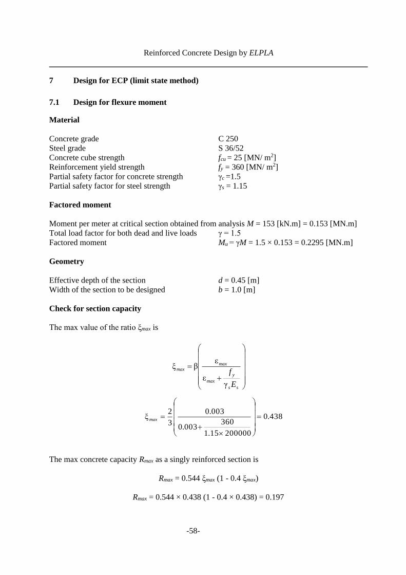
7 Design for ECP (limit state method)
7.1 Design for flexure moment
Material
Concrete grade C 250
Steel grade S 36/52
Concrete cube strength fcu = 25 [MN/ m2]
Reinforcement yield strength fy = 360 [MN/ m2]
Partial safety factor for concrete strength γc =1.5
Partial safety factor for steel strength γs = 1.15
Factored moment
Moment per meter at critical section obtained from analysis M = 153 [kN.m] = 0.153 [MN.m]
Total load factor for both dead and live loads γ = 1.5
Factored moment Mu = γM = 1.5 × 0.153 = 0.2295 [MN.m]
Geometry
Effective depth of the section d = 0.45 [m]
Width of the section to be designed b = 1.0 [m]
Check for section capacity
The max value of the ratio ξmax is
The max concrete capacity Rmax as a singly reinforced section is
Rmax = 0.544 ξmax (1 - 0.4 ξmax)
Rmax = 0.544 × 0.438 (1 - 0.4 × 0.438) = 0.197
+
=
ss
y
max
maxmax
E
f
γε
εβξ
438.0
20000015.1
360003.0
003.0
3
2ξ =
+
=max

Reinforced Concrete Design by ELPLA
-59-
The maximum moment Mu, max as a singly reinforced section is
Mu, max = 0.665 > Mu = 0.2295, then the section is designed as singly reinforced section.
Determination of tension reinforcement
The concrete capacity R1 is
The normalized steel ratio ω is
The required area of steel reinforcement per meter As is
As = 17.19 [cm2/ m]
Chosen steel 7 Φ 18/ m = 17.8 [cm2/ m]
2
γ , bd
fRM
c
cumaxmaxu =
[MN.m] 665.045.00.15.1
25197.0 2
, ==maxuM
21bdf
MR
cu
u=
045.045.00.125
2295.021 =
=R
( )141.411521.0ω R−−=
( ) 055.0045.041.411521.0ω =−−=
bdf
fA
y
cus ω=
m]/ [m 001719.045.00.1360
25055.0 2==sA

Reinforced Concrete Design by ELPLA
-60-
7.2 Check for punching shear
The critical punching shear section on a perimeter at a distance d/ 2 = 0.225 [m] from the face of
the column is shown in Figure 19.
Figure 19 Critical section for punching shear according to ECP
Geometry (Figure 19)
Effective depth of the section d = 0.45 [m]
Column side a = b = 0.4 [m]
Area of critical punching shear section Ap = (a + d)2 = (0.4 + 0.45)2 = 0.723 [m2]
Perimeter of critical punching shear section bo = 4 (a + d) = 4 (0.4 + 0.45) = 3.4 [m]
0.4
Pu =1.914 [MN]
qu = 0.293 [MN/m2]
0.85 m
0.225 0.225
bo = 3.4 [m]
Ap = 0.723 [m2]
d =0.45 [m]

Reinforced Concrete Design by ELPLA
-61-
Loads and stresses
Concrete cube strength fcu = 25 [MN/ m2]
Total load factor for both dead and live loads γ = 1.5
Partial safety factor for concrete strength γc = 1.5
Column load P = 1276 [kN] = 1.276 [MN]
Soil pressure under the column qo = 195 [kN/ m2] = 0.195 [MN/ m2]
Factored column load Pu = γ P = 1.5 × 1.276 = 1.914 [MN]
Factored soil pressure under the column qu = γ qo = 1.5 × 0.195 = 0.293 [MN/ m2]
Check for section capacity
The factored punching shear force Qup is
Qup = Pu - qu Ap
Qup = 1.914 – 0.293 × 0.723 = 1.702 [MN]
The punching shear stress qup is
The nominal concrete punching strength qcup is
qcup = 1.29 [MN/ m2]
qcup = 1.29 [MN/ m2] > qup = 1.112 [MN/ m2], the section is safe for punching shear.
db
up
up
o
=
]m[MN/ 112.145.04.3
702.1 2=
=upq
c
cu
c
cucup
ff
b
aq
γ316.0 ,
γ5.0316.0
+=
5.1
25316.0 ,
5.1
25
4.0
4.05.0316.0
+=cupq

Reinforced Concrete Design by ELPLA
-62-
8 Design for ECP (working stress method)
8.1 Design for flexure moment
Material
Concrete grade C 250
Steel grade S 36/52
Compressive stress of concrete fc = 95 [kg/ cm2] = 9.5 [MN/ m2]
Tensile stress of steel fs = 2000 [kg/ cm2] = 200 [MN/ m2]
Moment
Moment per meter at critical section obtained from analysis M = 153 [kN.m] = 0.153 [MN.m]
Geometry
Effective depth of the section d = 0.45 [m]
Width of the section to be designed b = 1.0 [m]
Check for section capacity
The value of the ratio ξ is
+
=
c
s
f
fn
nξ
416.0
5.9
20015
15ξ =
+
=

Reinforced Concrete Design by ELPLA
-63-
The coefficient k1 to obtain the section depth at balanced condition is
The maximum depth d m as a singly reinforced section is
d = 0.45 [m] > dm = 0.3 [m], then the section is designed as singly reinforced section.
Determination of tension reinforcement
Determine the neutral axis z corresponding to the depth d by iteration from
The value of the ratio ξ corresponding to the depth d is given by
=
3
ξ-1ξ
2 1
cf
k
767.0
3
0.416-1416.0.59
2 1 =
=k
b
Mkdm 1 =
[m] 3.00.1
153.0767.0 ==md
−=
3-
)(30
zdbf
zdMz
s
[m] 134.0
3-.4502000.1
)45.0(153.030 =
−=
z
zz
d
z=ξ
298.045.0
13.0ξ ==

Reinforced Concrete Design by ELPLA
-64-
The coefficient k2 [MN/ m2] to obtain the tensile reinforcement for singly reinforced section is
The required area of steel reinforcement per meter As is
As = 18.88 [cm2/ m]
Chosen steel 8 Φ 18/ m = 20.4 [cm2/ m]
−=
3
ξ12 sfk
13.1803
0.29812002 =
−=k
dk
MAs
2
=
m]/ [m 001888.045.013.180
153.0 2=
=sA

Reinforced Concrete Design by ELPLA
-65-
8.2 Check for punching shear
The critical punching shear section on a perimeter at a distance d/ 2 = 0.225 [m] from the face of
the column is shown in Figure 20.
Figure 20 Critical section for punching shear according to ECP
Geometry (Figure 20)
Effective depth of the section d = 0.45 [m]
Column side a = b = 0.4 [m]
Area of critical punching shear section Ap = (a + d)2 = (0.4 + 0.45)2 = 0.723 [m2]
Perimeter of critical punching shear section bo = 4 (a + d) = 4 (0.4 + 0.45) = 3.4 [m]
Loads and stresses
Column load P = 1276 [kN] = 1.276 [MN]
Soil pressure under the column qo = 195 [kN/ m2] = 0.195 [MN/ m2]
Main value of shear strength for concrete C 250 according to Table 4
qcp = 0.9 [MN/ m2]
d =
0.4
5 [
m]
qo = 0.195 [MN/ m2]
Ap = 0.723 [m2] bo = 3.4 [m]
P = 1.276 [MN]
0.225 0.4 0.225
0.4
0.4
0.2
25
0.4
0.2
25

Reinforced Concrete Design by ELPLA
-66-
Check for section capacity
The punching shear force Qo is
Qp = P – qo Ap
Qp = 1.276 – 0.195 × 0.723 = 1.135 [MN]
The punching shear stress qp is given by
The allowable concrete punching strength qpall [MN/ m2] is given by
qpall = 0.9 [MN/ m2]
qpall = 0.9 [MN/ m2] > qp = 0.742 [MN/ m2], the section is safe for punching shear.
db
p
p
o
=
]m[MN/ 742.045.04.3
135.1 2=
=pq
cpcppall qqb
aq
+= ,5.0
9.0 ,9.04.0
4.05.0
+=pallq


![Performance and Durability Evaluation of Bamboo Reinforced ... · ... bamboo reinforced beam [4]. Bamboo reinforced concrete design is similar to steel reinforced concrete design](https://img.dokumen.tips/doc/110x75/5b573ef17f8b9adf7d8d8ed2/performance-and-durability-evaluation-of-bamboo-reinforced-bamboo-reinforced.jpg)