Embed Size (px)
Citation preview

This equipment chapter is to be placed in the Toasters section of your Equipment Manual.
MANUFACTURED EXCLUSIVELY FORMcDONALD’S®
BY PRINCE CASTLE, INC.
355 E. KEHOE BLVD. CAROL STREAM, IL 60188 U.S.A
PHONE: 1 (630) 462-8800TOLL FREE NUMBER:
1 (800) 323-2930FAX: 1 (630) 462-1460
REGULAR BUN TOASTERPRINCE CASTLE MODEL 213-LFMCEC SERIES
213-LFKC SERIES AND 213-LFALC (AUSTRALIA)
TABLE OF CONTENTS
WARRANTY. . . . . . . . . . . . . . . . . . . . . . . . . . . . . . . . . . . . . . . . . . . . . . . . . . . . . . . . . Page 1INTRODUCTION. . . . . . . . . . . . . . . . . . . . . . . . . . . . . . . . . . . . . . . . . . . . . . . . . . . . . Page 2PARTS IDENTIFICATION AND FUNCTION. . . . . . . . . . . . . . . . . . . . . . . . . . . . . Page 2EXPLODED VIEW. . . . . . . . . . . . . . . . . . . . . . . . . . . . . . . . . . . . . . . . . . . . . . . . . . . . Page 5EQUIPMENT SET-UP AND CLOSE PROCEDURES. . . . . . . . . . . . . . . . . . . . . . . Page 6TROUBLESHOOTING GUIDE. . . . . . . . . . . . . . . . . . . . . . . . . . . . . . . . . . . . . . . . . .Page 7ORDERING PARTS/SERVICE. . . . . . . . . . . . . . . . . . . . . . . . . . . . . . . . . . . . . . . . . . Page 8NON-SCHEDULED MAINTENANCE. . . . . . . . . . . . . . . . . . . . . . . . . . . . . . . . . . . . Page 9WIRING INFORMATION. . . . . . . . . . . . . . . . . . . . . . . . . . . . . . . . . . . . . . . . . . . . . . Page 28
WARRANTY
This product is warranted to be free from defects in materials and/or workmanship for a periodof 12 months from date of purchase.
Any part or component which proves to be faulty in material or workmanship within 12 monthsfrom date of purchase will be replaced or repaired (at the option of Prince Castle, Inc.) withoutcost to the customer for parts and labor.
This warranty is subject to the following exceptions/conditions:
1) This equipment is portable; charges for on-location service (e.g. trip charges, mileage) are only included in the provisions of this warranty for a failure which occurs within 30days of installation.
2) Damage caused by carelessness, neglect, and/or abuse (e.g. using wrong current, dropping, tampering with or altering electrical components) voids this warranty.
This manual is for the exclusive use of licensees and employees of McDonald’s Systems, Inc.
©2003 McDonald’s Corporation Printed inAll Rights Reserved The United States of America
Printed in FebruaryPart No. 213-534RevA
EM T2

INTRODUCTION
The regular bun toaster caramelizes 12 complete regular buns or ¼ lbs. buns in 55 seconds when using flat grills, or in 35 seconds when using clamshell grills.
The crowns are placed on a bun tray containing a paper tray liner and put into the bottom of the toaster. When using 55 second toast, the heels are placed on top of the platen under the bun
board, when using 35 second toast, heels areplaced on the ¼ “ (6 mm) aluminum plate, resting on top of the platen. The handle is pulled down, lowering the platen onto the topof the crowns, (This also activates the timer),
After 55 seconds, or 35 seconds depending on the type of grill being used, a buzzer will soundand a bun ready light will come on indicating theend of the toasting cycle.
PARTS IDENTIFICATION AND FUNCTION
Adjusts the height of the platen. 6 stop positions from 35/64” to 1 11/64” (14 mm to 32 mm) on the bun crowns
1Stop Blocks (L.H. & R.H)213-306S6
Stud that holds the front lever to the platen and connects to helper spring.
2Bearing Stud212-286S18
Stud that holds the levers to platen4Bearing Stud212-285S17
Holds the front and rear levers to the toaster frame.
4Bearing Stud212-284S16
Aligns bearing studs in handle and lever assemblies.
4Bearing62-02115
Aligns bearing studs in handle and lever assemblies
4Bearing62-00514
Holds the rear of the platen in the toaster and allows for opening and closing the toaster.
2Rear Lever with Bearings212-701S 13
Elevates toaster to allow proper air circulation and cleaning.
4Rubber Foot89-595S10
Maintains alignment of levers and platen.4Spacer212-283S9
Mounts to the frame and holds helper springs.
1Spring Bracket212-2278
Holds stop blocks in position. 1Compression Spring81-0095
Locates the position of the stop blocks to the front levers and holds the compression spring in position.
1Washer, Notched213-1644
Holds stop blocks to toaster frame1Stop Block Rod416-292
FUNCTIONQTY.DESCRIPTIONPARTNO.ITEM
2

Holds the platen in the toaster and allows for raising and lowering the platen.
1Front Lever with Bearings213-12419
Attached to the platen to prevent buns from falling off the sides.
1L.H. Bun Fence213-64230
1R.H. Bun Fence231-64431
Helper spring to reduce lifting force1Spring215-7 20
Indicates power to the toaster. 1White Power Light71-134-248
Lights when toasting cycle has completed1Amber Bun Ready Light71-134-147
Protects the switch from touching metal1Switch Insulator416-4346
Starts the timer for toasting cycle1Timer Switch Kit78-146S45
Used to adjust thermostat1Knob222-102S44
Maintains and controls heat.1Thermostat222-122A42
Holds platen tubes in place.12Retainer—Thermal Break Tube
213-24540
Insulators that protect the heating element connectors and thermostat capillary tube.
3Platen Tube213-36439
Removable--allows access to enclosure1Cover212-22037
Bun Board (213-LFMNCE only)
213-671
Used as a bun weight to compress the heels to the platen for proper toasting.
1Bun Board213-38834
Attached to the platen to prevent buns from falling off the back.
1Upper Rear Bun Fence213-65133
Electrically heated toasting surface1Platen Kit213-8432
Attaches and positions the latch to the frame.
1Bracket, Safety Latch213-30528
When engaged holds the platen in the open (up) position.
1Safety Latch213-30327
Attachment and pivot point for the safety latch.
1Pivot, Safety Latch213-30125
Mounts to the frame to protect hands from touching the platen.
2Side Panel213-41623
Safety latch engaged attachment location1Platen Stud Safety Latch213-304S22
Attaches to side of toaster platen and holds helper spring
1Spring Link416-1321
FUNCTIONQTYDESCRIPTIONPARTNO.ITEM
3
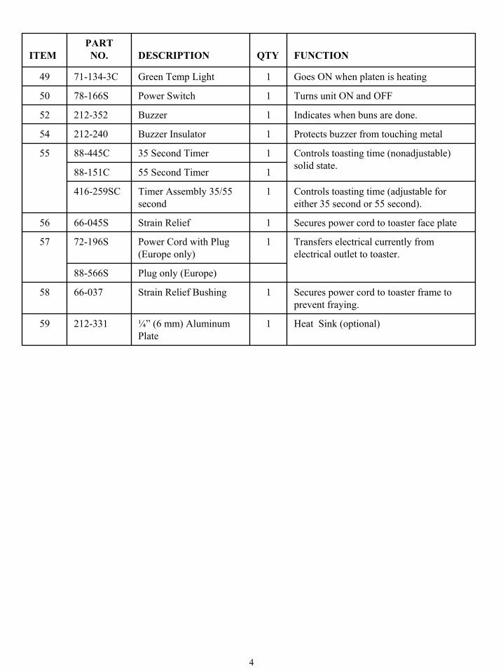
Heat Sink (optional)1¼” (6 mm) Aluminum Plate
212-33159
Secures power cord to toaster frame to prevent fraying.
1Strain Relief Bushing66-03758
Plug only (Europe)88-566S
Transfers electrical currently from electrical outlet to toaster.
1Power Cord with Plug (Europe only)
72-196S57
Secures power cord to toaster face plate1Strain Relief66-045S56
Controls toasting time (adjustable for either 35 second or 55 second).
1Timer Assembly 35/55 second
416-259SC
155 Second Timer88-151C
Controls toasting time (nonadjustable) solid state.
135 Second Timer88-445C55
Protects buzzer from touching metal1Buzzer Insulator212-24054
Indicates when buns are done. 1Buzzer212-35252
Turns unit ON and OFF1Power Switch78-166S50
Goes ON when platen is heating1Green Temp Light71-134-3C49
FUNCTIONQTYDESCRIPTIONPARTNO.ITEM
4

5

EQUIPMENT SET-UP AND CLOSE PROCEDURES
Set-up• See MRC 16 for proper cleaning procedures.
CAUTION: Before plugging in, make suretoaster is turned OFF.
1. Insert the power plug into a 16 Amp grounding receptacle.
2. Place the power switch in the ON position.3. Pull operating handle/link assembly forward and
down. This will activate timer assembly. After 55 ± 5 seconds, (or 35 ± 1 second when used with the clamshell grill) buzzer will sound and “Bun Ready Light” will come ON. Lift operating handle/link to deactivate.
4. Ensure platen is in the up position while the toaster warms up so that the timer is not activated.
5. Allow the toaster to warm up. Specific equipment warm up times are in the Operations and Training Manual.
6. Ensure stop blocks are on correct setting. (See Figure A)
NOTE: To change setting of stop block, depress the right stop block to disengage locking pin and turn in either direction to correct setting.
7. Unlock handle by moving safety latch from theplaten stud to the “UNLOCKED” position. (See Figure B)
This appliance is not of water tightconstruction. Do not clean this appliancewith a water jet/spray.
Do not immerse appliance in water.
!
!
8. To convert toaster (35 sec.) to (55 sec.), remove aluminum plate from top of platen. Turn 35-55 second timer select switch, locatedunderneath electrical box, to 55 second positionRecalibrate platen temperature from 420°F(216°C) ±5°F (±3°C) to 400°F (204°C) ±5°F(±3°C).
NOTE: Aluminum plate must be removed prior to calibration.
CloseCAUTION: Before unplugging, make sure toaster is turned OFF.
1. Place the power switch in the OFF position.2. Unplug toaster. 3. Allow toaster platen to cool. 4. Wipe entire platen clean with clean damp
grill cloth. Full toaster cleaning must be donein the morning when the toaster is cold.
CAUTION: Do not drape cord over hot toasterbun board or platen as it will burn cord. 6
FIGURE A
1
2
3
Left SidePanel
Stop Block
Pin StopBracket
LOCKEDPOSITION
SAFETY LATCHBEARING STUD
STOPTAB
SAFETY LATCHBRACKET
MOUNTING BOLT SAFETYLATCH
SAFETY LATCH LABEL
Figure B

TROUBLESHOOTING GUIDE
NOTE: Service is to be performed by qualifiedservice personnel.
WARNING: Inspection, testing and repair ofelectrical equipment should be performed only by qualified service personnel. The unit
should be unplugged when servicing, exceptwhen electrical tests are required.
DANGER: Use extreme care during electrical circuit tests. Live circuits will be exposed.
Change bun board item #35. Wrong bun board being used.
Replace plate. Aluminum plate missing on 35 second toast.
Bun heels not toasting properly on 35 or 55 second toast.
Check position of timer select switch. Set it at 55 seconds. Recheck time.
Timer assembly set incorrectly. Timer assembly sounds at 35 seconds rather than 55 seconds.
Clean platen. See 16.Build up of sugar on platen.
Recalibrate thermostat. See MRC 16.Excessive heat. Buns sticking to platen.
Replace platen. Call service agency. Platen burned out or shorted.
Replace thermostatDefective thermostat
Correct as necessary. See MRC 17.Loose wiring.
Replace power switch. Power switch defective.
Check power source. No power. Platen does not heat.
Straighten or replace bun platform. Warped bun platform.
Contact bakery. Buns cut improperly.
Straighten or replace bun trays. Warped bun trays.
Adjust stop blocks.Stop blocks not adjusted properly. Buns being crushed.
Replace buzzer.Buzzer burned out. Amber Bun Ready light goes on but buzzer does not work.
Adjust timer switch stroke. Timer switch not adjusted.
Replace timer assembly.Defective timer assembly
Replace timer switch. Defective timer switch.No buzzer or Bun Ready light.
Replace light.Light burned out. Buzzer works, no Bun Done light
Tighten platen bolts. See MRC 16Platen bolts loose. Platen loose
CORRECTIVE ACTIONPROBABLE CAUSEPROBLEM
7

ORDERING/SERVICE IMFORMATION
Contact your kitchen Equipment Supplier ordesignated repair facility for parts and service.
1. PARTS RETURNSShould the need ever arise to return parts to your Center for credit, it is necessary that you: • Obtain authorization from your Service
Center for such return; • All warranty situations should be handled
by your Service Center.
2. PRICES:A. All prices are F.O.B Prince Castle Service
Center or F.O.B. factory, Carol Stream, Illinois.
B. All prices are subject to change withoutnotice. These prices are exclusive of allsales taxes or any special taxes which may be levied by federal, state or citygovernments.
3. TERMSNet 30 days.
INSPECTCARTON
Remove product from carton . . . .If damaged: • Notify carrier• Save carton and packing material• Contact Prince Castle Customer Sales
for replacement.
8

NON-SCHEDULED MAINTENANCE
Under normal conditions with proper use and cleaning,very little non-scheduled maintenance will be required
for this toaster. However, this section provides pro-cedures for checking and replacement of the various parts used within the toaster in the event that it becomes necessary. Before replacement of any parts refer to the Troubleshooting section for assistance in de-terminating the cause of any malfunction.
GENERAL INSTRUCTIONS
!The power cord shall only be re-placed with an oil resistant rubbertype cord that has a minimum temperature rating of 90°C.
ELECTRICAL REPAIRSSTANDARD PROCEDURE FOR ALL ELECTRICALREPARIS: PLACE POWER SWITCH IN OFF POSI-TION & UNPLUG TOASTER.
When replacing any electrical controls mounted in the control box, the disassembly of the follow-ing is standard procedure (except where noted):
A. Remove 2 screws from electrical box cover. B. Remove cover. C. Remove 6 screws from faceplate.
REPLACE PLATEN
This procedure should be done by a qualified service technician.
REPLACE LIGHTS
1. Locate inoperable light. 2. Disconnect the 2 wires from the light. 3. Remove the light by squeezing the bezel clips
while pulling the light away from the control panel.
4. Reverse procedure to install new light.
REPLACE POWER SWITCHTools: Flatblade screwdriver.
1. Turn OFF and unplug toaster. WARNING: Failure to do so will result in elec-trical shock. 2. Remove power switch by squeezing Bezel
clips on switch and pushing switch out ofcontrol box.
3. Remove wires from switch. Refer to wiringdiagram for wiring connections.
4. Replace by reverse procedure.
REPLACE POWER CORD Tools: Flatblade screwdriver
1. Turn OFF and unplug toaster. WARNING: Failure to do so will result in electrical shock. 2. The power switch will have to be removed
to get at the power cord wires that connect to the bottom terminal.
9
Whenever you disconnect any electrical wires mark them in some way that will indicated to you which terminal they came from. Do not disconnect too many electrical connections at one time. Should you forget where a wire connects, refer to the individual wiring diagram for the particular control being replaced.
You will note that there are three basic methods of affixing wires to their terminals: (1) closed eye;( 2) spade; (3) knife and blade
DO NOT WRAP BARE WIRE UNDER A TER-MINAL HEAD SCREW, USE PROPER TERMINALS.
Before attempting to repair your toaster, you must:
A. Turn OFF and unplug toaster. B. Disconnect electrical supplyWARNING: Failure to do so will result inelectrical shock. C. Permit the unit to cool completely.
Finally: Make good use of the “Explode View” and parts pictures in this chapter to further aidyou in understanding the physical make-up ofyour toaster and the re-assembling of its components.

3. Disconnect green/yellow ground wire fromface plate.
4. Disconnect brown wire from the power switch.
5. Disconnect blue neutral wire from top ofpower switch for 115V units. For 200/220Vunits, disconnect blue neutral wire from bottom of power switch.
6. Remove cord from faceplate by removing strain relief bushing.
7. Reverse procedure to re-install power cord.
REPLACE BUZZER (See Figure 4)
Tools: Flatblade screwdriver.
1. Turn OFF and unplug toaster. WARNING: Failure to do so will result in electrical shock.
2. Remove screw holding buzzer to faceplate. 3. Cut 2 wires from buzzer. 4. Strip about ½” (13 mm) of insulation from
each end of the wires that were cut. 5. Connect new buzzer with wire nuts.
REPLACE THERMOSTAT(See Figure 4)
Tools: Fladeblade screwdriver
1. Turn OFF and unplug toaster. WARNING: Failure to do so will result inelectrical shock.
2. Unscrew retaining nut on outside of electrical box.
3. Remove switch from electrical box. 4. Remove 2 wires from thermostat terminals.5. Remove thermostat bulb retainer from
electrical box. 6. Remove thermostat and sensing bulb. 7. Replace with new thermostat by reverse
procedure making sure to coat new therm-ostat bulb with thermo-coat provided.
8. Calibrate as outline on Planned Main-tenance Card 16.
REPLACE TIMER SWITCH(See Figure 2 & 4)
Tools: Flatblade screwdriver
1. Turn OFF toaster and unplugWARNING: Failure to do so will result inelectrical shock.
2. Unscrew retaining nut on outside of electrical box.
3. Remove switch from electrical box. 4. Remove retaining ring and insulator from
switch. 5. Remove 2 wires from switch. 6. Mount 2 wires on new switch. 7. Insert new switch into insulator. 8. Position retaining ring on new switch
¼” (6 mm) from end of bushing.
NOTE: Insulator should be placed betweenswitch body and retaining ring. (See Figure 2)
10

9. Install new switch into electrical box andtighten retaining nut on outside of electrical box.
10. Set stop blocks at lowest position. 11. Lower platen slowly and watch movement
of new switch against actuator bracket.
NOTE: When platen is all the way down, thereshould be no more than a 1/32” (1 mm) clearancebetween threaded switch bushing and actuator bracket.
NOTE: The threaded switch bushing must notpress against the actuator bracket.
12. To adjust actuator bracket, loosen mount-ing screws and move bracket until 1/32” (1 mm) clearance is attained as shown inFigure 3 below. Re-tighten mountingscrews when bracket is in position.
13. Tighten retaining nut against chassis toprevent movement.
REPLACE TIMER ASSEMBLY(See Figure 4)
Tools: Flatblade screwdriver
1. Turn OFF and unplug toaster. WARNING: Failure to do so will result in electrical shock.
2. Remove 2 wires from timer assembly. 3. Remove screw and nut holding timer
assembly to bottom of electrical box. 4. Remove timer assembly. 5. Replace with new timer assembly by
reverse procedures.
11
BUZZER THERMOSTAT
INSULATOR TIMERSWITCH
TIMERASSEMBLY
Figure 4
RETAINING NUT
¼” (6 MM)
SWITCH BODY
INSULATOR
RETAINING RINGELECTRICAL BOX
Figure 2
ACTUATORBRACKET
FRAME
ELECTRICAL BOX
THREADED SWITCH BUSHING
MOUNTING SCREWS
Figure 3

MISE EN PLACE DE L’APPAREILET PROCÉDURES DE MISE HORS TENSION
Mise en place• Voir MRC 16 pour les techniques de nettoyage
correctes.
ATTENTION: Avant de brancher l’appareil,assurez-vous que le grille-pain est éteint (OFF).
1. Branchez le cordon d’alimentation sur une prise mise à la terre de 16 amp. Placez l’interrupteur principal sur “ON”(MARCHE).
2. Placez l’interrupteur principal sur ON.3. Tirez sur la manette/amillon vers l’avant et vers le bas.
Vous enclencherez ainsi la minuterie. Après 55 ±5 secondes, (ou 35 ± 1 secondes lorsque utilisée avec le grilà double coque) un avertisseur sonore retentira et le voyant indiquant que les pains sont prêt s’allumera (ON). Soulevez la manette/mailion pour mettre hors circuit.
4. Assurez-vous que la presse est droite pendant que le grille-pain chauffe afin d’éviter de mettre en marche la minuterie.
5. Laissea chauffer le grille-pain. Les temps d’échauffementde certains appareils se trouvent dans la notice d’exploitation et d’entraînement.
6. Assurez-vous que les butêes de sécurité sontcorrectement réglées. (Voir Figure A)
REMARQUE: Pour modifier le réglage de la butéede sécurité, appuyez sur la butée droite afin de relâcher le boulon de fixation et tournez pour régler.
7. Débloquez la manette en plaçcnt le goujonde la presse sur la position “UNLOCKED”( NON FERMÉE). (Voir Figure B)
Cet appareil n’est pas etanche. Ne pas nettoyer cet appareil au jet d’eau ou avecnettoyeur haute pression.
Ne pas placer cet appareil dans de l’eau.
!
!
8. Pour transformer le grille-pain (35 sec.) en grille-pain (55 sec.), retirez la plaque d’aluminum (article 59) du dessus de la presse. Tournez le bouton de sélection des minuteries35-55 seconds situé sous la boîte electrique afinde le placer sur la position 55. Réglez ànouveau la température de la presse de 420°F (216°C) ±5°F (±3°C) to 400°F (204°C) ±5°F (±3°C).
REMARQUE: La plaque d’aluminium doit êtreretirée avant l’étalonnage.
FermetureAttention: Avane de dêbrancher l’appareil, assurez-vous le grille-pain est éteint (OFF).
1. Éteignez l’appareil en plaçant l’interrupteurprincipal ser OFF.
1. Débranchez le grille-pain. 2. Laissez refroidir la presse du grille-pain. 3. Essuyez entiérement la presse à l’aide d’un
chiffon propre et humide. Nettoyez entiérementle grille-pain le matin lorsque cer dernier estfroid.
Attention: Ne pas faire passer le cordon d’alimentation sur la plaque des petits painsou sur la presse car vous brûlerez ce dernier. 12
1
2
3
PanneauGauche
ButéeDe Sécurité
Support De La ButéeDe Clavette
BOULONDE MONTAGE
LINGUETDE SÉCURITÉ ANCRAGE
DU LINQUETDE S
CRAN DE SÉCURITÉ
SUPPORT DU LINGUETDE SÉCURITÉ
POSITION FERMÉE
ÉTEQUETTEDU LINGUETDESÉCURITÉ

GUIDE DE DÉPANNAGEREMARQUE: Tout service d’entretien doit êtreeffectuê par du personnel qualifié.
AVERTISSEMENT: Faîtes faire essai, révision ouréparation par du personnel qualifié. Débrachez
l’appareil pour toute opération d’entretienexcepté. lorsque des essais électriques sontnécessaires.DANGER: Faîtes preuve d’une extrêmeprudence lors des essais électriques. En effet, des circuits sous tension risquent d’être àdécouvert.
Changez l’article no. 35 de la planche à petitspains.
La planche des petits pains utiliséen’estpas la bonne.
Replacez la plaque. La plaque d’aluminium du grille-pain de 35 secondes est manquante.
Les croûtons des petits pains ne grillent pas correctementquel que soit le réglage (35 ou55 secondes).
Vérifiez la position de l’interrupteur de sélection de minuterie. Réglez-le à 55 seconds. Vérifiez à nouveau le temps affiché.
La minuterie a été mal réglée. L’avertisseur sonne à 35 secondes au lieu de 55 secondes.
Nettoyez la presse. Voir MRC 16.Accumulation de sucre sur la presse.
Étalonnez à nouveau le thermostat. Voir MRC 16.
Chaleur excessive. Les petit pains demeurentcollés à la presse.
Remplacez la presse. Appelez l’agenceréparatrice.
Les presse est grillée ou il y a eu court-circuit.
Remplacez le thermostat. Appelez l’agenceréparatrice.
Le thermostat est défectueux.
Corrigez comme il se doit. Voir MRC 17.Le câblage est desserré.
Remplacez l’interrupteur principal. L’interrupteur principal est défectueux.
Vérifiez l’alimentation électrique. Pas de courant. La presse ne chauffe pas.
Redressez ou remplacez la plate-forme des petits pains.
La plate-forme des petits pains estdéformée.
Contactez la boulangerie. Les petits pains ont été mal coupés.
Redressez ou remplacez les plateaux des petitspains.
Les plateaux des petits pains sontdéformés.
Réglez les butées de sécurité.Les butées de sécurité ne sont pas réglées correctement.
Les petit pains sont écrasés.
Remplacez l’avertisseur sonore.Avertisseur sonore hors d’état de fonctionnement..
Le voyant ambre s’allumemais pas d’avertisseur sonore.
Réglez pas de l’interrupteur de la minuterie.. L’interrupter de la minuterie n’est pas réglé.
Remplacez la minuterie.La minuterie est défectueuse
Remplacez l’interrupteur de la minuterie. L’interrupteur de la minuterie estdéfectueux.
Pas d’avertisseur sonore ni de voyant.
Remplacez le voyant.Voyant grillé. Avertisseur sonore mais pas de voyant indiquant que les pains sont cuits.
Serrez les boulon de la presse. Voir MRC 16Les boulons de la presse sont desserrés. Presse desserrée.
SOLUTIONCAUSE PROBABLEPROBLÉME
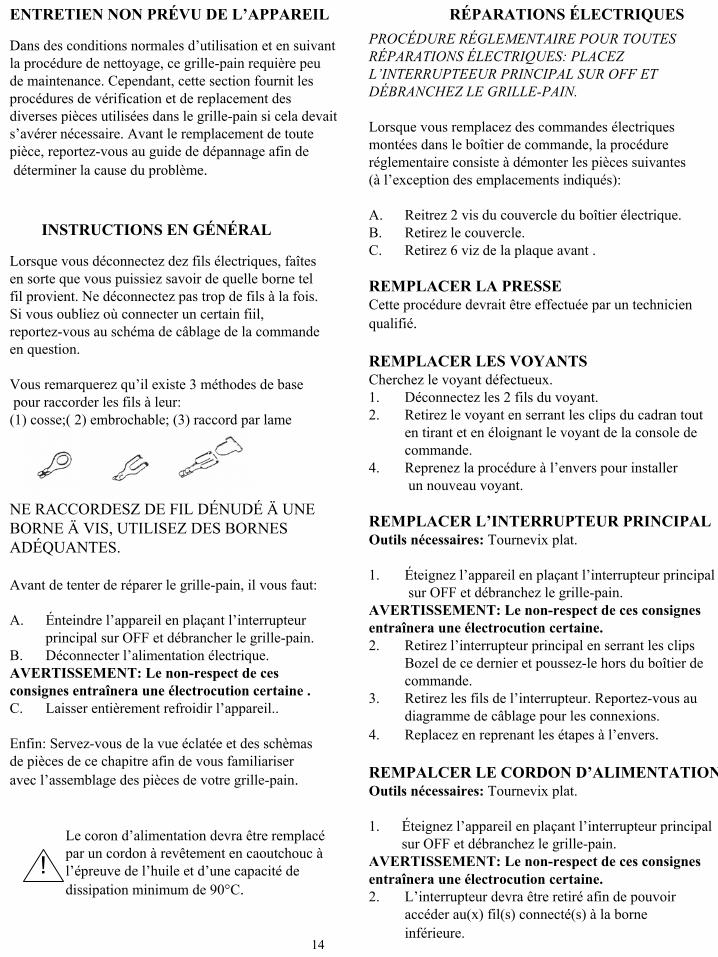
ENTRETIEN NON PRÉVU DE L’APPAREIL
Dans des conditions normales d’utilisation et en suivantla procédure de nettoyage, ce grille-pain requière peude maintenance. Cependant, cette section fournit lesprocédures de vérification et de replacement des diverses pièces utilisées dans le grille-pain si cela devaits’avérer nécessaire. Avant le remplacement de toutepièce, reportez-vous au guide de dépannage afin dedéterminer la cause du problème.
INSTRUCTIONS EN GÉNÉRAL
!Le coron d’alimentation devra être remplacépar un cordon à revêtement en caoutchouc àl’épreuve de l’huile et d’une capacité de dissipation minimum de 90°C.
RÉPARATIONS ÉLECTRIQUESPROCÉDURE RÉGLEMENTAIRE POUR TOUTES RÉPARATIONS ÉLECTRIQUES: PLACEZ L’INTERRUPTEEUR PRINCIPAL SUR OFF ET DÉBRANCHEZ LE GRILLE-PAIN.
Lorsque vous remplacez des commandes électriquesmontées dans le boîtier de commande, la procédureréglementaire consiste à démonter les pièces suivantes(à l’exception des emplacements indiqués):
A. Reitrez 2 vis du couvercle du boîtier électrique. B. Retirez le couvercle. C. Retirez 6 viz de la plaque avant .
REMPLACER LA PRESSE Cette procédure devrait être effectuée par un technicienqualifié.
REMPLACER LES VOYANTSCherchez le voyant défectueux. 1. Déconnectez les 2 fils du voyant. 2. Retirez le voyant en serrant les clips du cadran tout
en tirant et en éloignant le voyant de la console de commande.
4. Reprenez la procédure à l’envers pour installerun nouveau voyant.
REMPLACER L’INTERRUPTEUR PRINCIPALOutils nécessaires: Tournevix plat.
1. Éteignez l’appareil en plaçant l’interrupteur principalsur OFF et débranchez le grille-pain.
AVERTISSEMENT: Le non-respect de ces consignesentraînera une électrocution certaine. 2. Retirez l’interrupteur principal en serrant les clips
Bozel de ce dernier et poussez-le hors du boîtier de commande.
3. Retirez les fils de l’interrupteur. Reportez-vous audiagramme de câblage pour les connexions.
4. Replacez en reprenant les étapes à l’envers.
REMPALCER LE CORDON D’ALIMENTATIONOutils nécessaires: Tournevix plat.
1. Éteignez l’appareil en plaçant l’interrupteur principalsur OFF et débranchez le grille-pain.
AVERTISSEMENT: Le non-respect de ces consignesentraînera une électrocution certaine.2. L’interrupteur devra être retiré afin de pouvoir
accéder au(x) fil(s) connecté(s) à la borne inférieure.
14
Lorsque vous déconnectez dez fils électriques, faîtesen sorte que vous puissiez savoir de quelle borne telfil provient. Ne déconnectez pas trop de fils à la fois.Si vous oubliez où connecter un certain fiil,reportez-vous au schéma de câblage de la commandeen question.
Vous remarquerez qu’il existe 3 méthodes de basepour raccorder les fils à leur:
(1) cosse;( 2) embrochable; (3) raccord par lame
NE RACCORDESZ DE FIL DÉNUDÉ Ä UNE BORNE Ä VIS, UTILISEZ DES BORNES ADÉQUANTES.
Avant de tenter de réparer le grille-pain, il vous faut:
A. Énteindre l’appareil en plaçant l’interrupteurprincipal sur OFF et débrancher le grille-pain.
B. Déconnecter l’alimentation électrique. AVERTISSEMENT: Le non-respect de cesconsignes entraînera une électrocution certaine . C. Laisser entièrement refroidir l’appareil..
Enfin: Servez-vous de la vue éclatée et des schèmasde pièces de ce chapitre afin de vous familiariseravec l’assemblage des pièces de votre grille-pain.

3. Déconnectez le fil de terre vert/jaune de la plaqueavant
4. Déconnectez le fil marron de l’interrupteur principal. 5. Déconnectez le fil neutr bleu de la partie supérieure
de l’interrupteur principal pour les modèles 200/220V, dèconnectez le fil neutre bleu de la partie inférieurede l’interrupteur pricipal.
6. Retirez le cordon de la plaque avant en retirant la bague de renforcement.
7. Reprenez la procédure à l’envers pour installer ànouveau le cordon d’alimentation.
REMPLACER L’AVERTISSEUR SONORE(Voir Figure 4)
Outils nécessaires: Tournevis plat.
1. Éteignez l’appareil en plaçant l’interrupteurprincipal sur OFF et débrachez le grille-pain.
AVERTISSEMENT: Le non-resspect de cesconsignes entraînera une électrocution certaine.
2. Retirez la vis retenant l’avertisseur sonore àla plaque avant..
3. Coupez les 2 fils d l’avertisseur sonore. 4. Dénudez environ ½ pc. (13 mm) de l’isolant
à chaque extrémité des fils qui ont été coupés.5. Connectez le nouvel avertisseur sonore à
l’aide des écrous de câbles.
REMPLACER LE THERMOSTAT(Voir Figure 4)
Outils nécessaires: Tournevis plat.
1. Éteignez l’appareil en plaçant l’interrupteurprincipal sur OFF et débrachez le grille-pain.
AVERTISSEMENT: Le non-respect de cesconsignes entraînera une électrocution certaine.
2. Retirez le bouton en desserrant la petite vis dece dernier.
3. Retirez les 2 vis retenant le thermostat et la plaque du cadran à pl plaque avant.
4. Retirez les duex fils des bornes du thermostat. 5. Retirez le porte-ampoule du thermostat du boîtier
électrique. 6. Retirez le thermostat et l’ampoule sensible.7. Remplacez par un nouveau thermostat en
reprenant le procédure à l’envers et en vousassurant de bien recouvrir la nouvelle ampouledu thermostat avec la proctecion thermiquefournie.
8. Étalonnez comme indiqué sur la carte desspécifactions de maintenance no 16.
REMPLACER L’INTERRUPTEUR DE LA MINUTERIE (Voir Figures 2 & 4)
Outils nécessaires: Tournevis plat.
1. Éteignez l’appareil en plaçant l’interrupteurprincipal sur OFF et débrachez le grille-pain.
AVERTISSEMENT: Le non-respect de cesconsignes entraînera une électrocution certaine.2. Dévissez l’écrou de sécurité à l’extérieur
du boîtier électrique.3. Retirez l’interrupeur du boîtier électrique. 4. Retirez la bague de retenue et l’isolant de
l’interrupteur. 5. Retirez les 2 fils de l’interrupteur. 6. Fixez les 2 fils sur le nouvel interrupteur. 7. Insérez le nouvel interrupteur dan l’isolant. 8. Placez la bague de retenue sur le nouvel
interrupteur à ¼ de pc. (6 mm) del’extrémité de la bague.
REMARQUE: L’isolant devrait être placé entrele corps de l’interrupteur et la bague de retenue. (Voir Figure 2)
15

9. Installez le nouvel interruteur dans leboîtier électrique et serrez l’écrou de sécurité à l’extérieur du boîtier électrique
10. Réglez les butées à la position la plus basse. 11. Abaissez lentement la presse et observez el
mouvement du nouvel interrupteur contrele support du dispositif d’attaque.
REMARQUE: Lorsque la presse estentiérement baissée, il devrait y avoir un espaced’environ 1/32 de pc. (1 mm) entre la baguetaradée de l’interrupteur et le support du dispositif d’attaque.
REMARQUE: La bague taraudeé del’interrupteur ne doit pas pousser contrele support du dispositif d’attaque.
12. Pour régler le support du dispositifd’attaque, desserrez les vis de montage et déplacez le support jusqu’à obtenirun espace d’1/32 de pc. (1 mm) commeillustré àla Figure 3 ci- dessous. Serrez ànouveau les vis de montage lorsque le support est en place.
13. Serrez l’écrou de sécurité contre le châssis afin d’éviter tout mouvement.
REMPACER LA MINUTERIE(Voir Figure 4)
Ousils nécassaries: Tournevis plat.
1. Éteignez l’appareil en plaçantl’interrupteur principal sur OFF et débranchez le grille-pain.
AVTISSEMENT: Le non-respect de ces consignes entraînera une électrocutioncertaine.
2. Retirez les 2 fils de la minuterie. 3. Retirez la vis et l’écrou retenant la
minuterie au dessous de boîtierélectrique.
4. Retirez la minuterie. 5. Remplacez par une nouvelle
minuterie en reprenant la procédureà l’envers
16
ISOLANTINTERRUPTEUR
DE LA MINUTERIEAVERTISSEUR
SONORE
MINUTERIE THERMOSTAT
Figure 4
BOÍTIERÉLECTRIQUESUPPORT DU
DISPOSITIFD’ATTAQUE
CADRE
VIS DE MONTAGE
BAGUETARADÉE DE
L’INTERRUPTEUR
Figure 3
ÉCROUDE SÉCURITÉ
BOÍTERÉLECTRIQUE
BAGUE DERETENUE
ISOLANT
CORPS DEL’INTERRUPTEUR
¼ de pc (6 mm)
Figure 2

Einschalt- und Abschaltvorgang des Gerätes
Einshalten• Siehe MRC-Karte 16 für richtige
Reinigungsvorgänge.
VORSICHT: Vor Netzancshluβ bitte versichern, daβ der Toaster ausgerschaltet ist.
1. Schlieβen Sie das Netzkabel an eine geerdete Steckdosean. Schalten Sie den Netzschalter is die ON-Position.
2. Den Netzchalter einschalten.3. Den Bedienhebel nach vorn und unten ziehen, dadurch
wird der Timer aktiviert. Nach 55 ± 5 Sekunden (oder 35 ± 1 Sekunde bei Verwendung des gescholssenen Grills) ertönt ein Signal und die “Bun Ready” Lampe erleuchtet. Zzum abschalten den Bedienhebel anheben.
4. Versichern, daβ sich die Heizplatte während demAufwärmen in der Offenposition befindet, damit der Timer nicht aktiviert wird.
5. Den Toaster aufwärmen lassen. Entsprechendeaufwärmzeiten der Geräte werden in der Arbeitsablauf-und Training-Anleitung angegeben.
6. Versichern, daβ die Anschlagblöchke ritchtigeingestellt sind. (Siehe Abbildung A)
HINWEIS: Unm die Einstellung des Anschlags zuändern, den rechten Anschlag eindrücken, um die Sicherung mit dem Feststellstift zu lösenund in beliebiger Richtung bis zur richtigenEinstellung drehen.
7. Den Griff durch Umlegen der Sicherheitslasche, con dem Heizplattenstift auf die “UNLOCKED” Stellung, gerischerte (SieheAbbildung B).
Dieses Gerät ist nicht wasserdicht. ReinigenSie dieses Gerät nicht mit einem Wasser-Hochdruckreiniger.
Nicht in Wasser tauchen.
!
!
8. Die Aluminum platte von der oberen Heizplattentffernen um den Toaster (35 Sek.) auf einenToaster (55 Sek.) umzustellen. Den 35-55 Sekunden Timer-Wahlschalter, unter der Verkbelungsbox, auf 55 Sekunden einstellen. Die Heizplatten-Temperatur nochmals von 216°C ±3°C (420°F ±5°F) auf 204°C ±3°C (400°F ±5°F) kalibrieren.
HINWEIS: Die Aluminumplatte muβ von demKalibrieren entfernt werden.
AbschaltenVorsicht: Vor dem abziehen desNetzsteckersversichern, daβ der Toaster augeschaltet ist.
1. Den Netzschalter in die OFF-Position schalten.2. Das Netzkabel des Toasters abziehen. 3. Die Heizplatten abkühlen lassen.4. Die gesammte Heizplatte mit einem sauberen
und fuechten Grill-Tuch abwischen. EineVollreinigung muβ morgens vorgenommenwerden, wenn der Toaster kalt ist.
VORSICHT: Das Netzkabel nicht über eineheiβe Brötchenablage oder Heizplatte hängen,da dises verschmoern kann. 17
1
2
3
LINKESEITENABDECKUNG
ANSCHLAG
ANSCHLAGPLATTEFÚR STIFT
HALTERUNG FÜRSICHRHEITSLASCHÉ
HALTEBOLZEN SICHERHEITSLASCHENABE FÜRSICHERHEITSLASCHE
GESICHERTESTELLUNGANSCHLAGPLATTE
SICHERHEITSLASCHEN-AUFKLEBER
ABBILDUNG B

GUIDE DE DÉPANNAGEHINWEIS: Wartung, darf nur durch qualifiziertesFachpersonal durchführt werden.
WARNUNG: Inspektionen, Prügungen undReperaturen elektrischer Geräte solite nurwon qualifiziertem Wartungspersonal durchgeführt
werden. Bei Wartung solite der Netzsteckerabgezogen werden, es sei denn, wenn elektrischeTests vorgenommen werder müssen.
GEFAHR: Bei elektrischen Test sehrvorsichtig sein. Stromführende Teile werdenzugänglich.
Brötchentablett #35 auswechsein. Falsches Bröchentablett wirdverwendet.
Aluminiumplatte einsetzen. Aluminiumplatte fehlt bei 35 Sekunden Toast.
Untere Brötchenhälfte toastennicht richtig bei 35 odor 55 Sekunden Toast
Position des Timerwahl-schalters prüfen. Auf 55 Sekunden einstellen und Zeitmessung durchführen.
Timer ist nicht richtig eingestellt. Der Timer gibt nach 35 Sekunden anstelle von 55 Sekunden ein Signal ab.
Heizplatte reinigen. Siehe 16.Zuckerablagerungen auf der Heizplatte.
Thermostat kalibrieren. Siehe MRC 16.Ümbermäβinge HitzeBrötchen kleben an der Heizplatte.
Heizplatte ersetzen. Mit WartungsdienstKontakt aufnehmen.
Heizplatte ist durchbebrannt oderkurzgeschlossen.
Thermostat ersetzenThermostat ist defekt
KAbel befestigen. Siehe MRC 17.Verkabelung ist lose.
Netzshalter ersetzen. Netzschalter ist defekt.
Spannungsquelle prüfen. Spannung ist nicht vorhanden. Heizplatte wird nicht heiβ.
Brötchenplattform gerade biegen oderersetzen
Brötchenplattform ist verbogen.
Mit der Bäkerei Kontakt aufnehmen. Brötchen sind nicht richtiggeschnitten.
Brötchentabletts gerade biegen oderersetzen.
Brötchentabletts sind verbogen.
Anschläge einstellen.Anschläge sind nicht richtigeingestellt.
Brötchen werden zerdrückt.
Summer ersetzen.Summer is defekt .Gelbe Bun Ready Anzeigeerleuchtet Signal ertönt nicht.
Auslösung des Timer-Schalters einstellen. Timer-Schalter isnt nicht eingestellt.
Timer ersetzen.Timer is defekt
Timer-Schalter ersetzen. Timer-Schalter ist defekt.Signal ertönt nicht und sieBun Ready Anzeige erleuchtetnicht. .
Lampe ersetzen.Lampe ist durchgebrannt. Signal ertönt, Bun Done Anzeige erleuchtet nicht.
Bolzen der Heizplatten anziehen. SieheMRC 16
Heizplattenbolzen sind lose. Lose Heizplatte
FEHLERBEHEBUNGWAHRSCHEINLICHE URSACHE
PROBLEM

Nicht geplante Wartung
Unter normalen Bedingungen bei korrekterAnwendung und Reinigung, werden für diesenToaster nur wenige nicht geplante Wartungennötig sein. In diesem Kapitel werden Vorgängezum Prüfen und Austauschen der verschiedenenKomponenten dieses Toasters aufgeführt, imFall Wartungen werden nötig. Vor dem Austauschenjeglicher Teile, nehmen die die Tabelle fürFehlersuche zu Hilfe, um den Grund der Fehlfunktionherrauszufinden.
ALLEGEMEINCE ANLEITUNG
!Das Netzkabel solltenur mit einem ölfestenKabel aus Gummi ersetzt werden, welcheseine Temperaturbeständigkeit von 90°C aufweist.
ELEKTRISCHE REPARATURENNORMALE WORGEHENSWEISE FÜR ALLE ELEKTRISCHEN REPARATURNE: DEN NETZ-SCHALTER IN DIE “off” POTION SCHALTEN UND DEN NETZSTECKER ABZIEHEN.
Bei ersetzen von jelichen elektrischen Reglern inder Regelbox ist folgendes die normaleVorgehensweise.A. 2 Schraubne von der Abdeckung der
Verkabelungs box entfernen. B. Abdeckung entfernen. C. 6 Schrauben der Vorderabdeckung
entfernen.
ERSETZEN DES HEIZPLATTEDies sollte von einem qualifiziertenWartungstechniker durchgeführt werden.
ERSETZEN DER LAMPEN
1. Defekte Lampe lokalisieren. 2. 2 Kabel von der defekten Lampe entfernen. 3. Lampe durch zusammen drücken der
Lampenhülse und nach vorn herrausziehenentfernen.
4. Einbau einer neuen Lampe erfolgt in umgekehrter Reihenfolge.
ERSETTZEN DES NETZSCHALTERSWerkzeug: Schraubenzieher (flach).
1. Toaster ausschalten und Netzstecker abziehen. WARNUNG: Bei nicht beachten könnenStromschläge erfolgen. 2. Entfernen Sie den Netzschalter, durch
Zasammendrücken der Clips am Lampenhalterund drücken Sie den Schalter aus der
Verkabelungsbox. 3. Entfernen Sie die Kabel von dem Netzchalter.
Siehe Schaltplan für Kabelaschlüsse. 4. Einbau erfolgt in umgekehrter Reihenfolge.
ERSETZEN DES NETZKABELSWerkzeug: Schraubenzieher (flach)
1. Toaster ausschalten und Netzstecker abziehen. WARNUNG: Bei nicht beachten könnenStromschläge erfolgen. 2. Der Netzschalter muβ entfernt werden,
um an das Netzkabel, welches an der Unterseitedes Netzschalters angeschlossen ist, zu gelangen19
Wenn Kabel entfernt werden, markieren Sie diseseimmer so, damit Sie wissen von welchem Anschluβdiese abgenommen wurden. Entfernen Sie niemelszu viele Kabel auf einmal. Sollten Sie vergessen woein estimmtes Kabel angeschlossen war, sehen Sie auf dem Schaltplan für das entsprechende Teil nach.
Sie werden sehen, daβ 3 Hauptmethoden zum Anschluβvon Kabe in verwendet werden: (1) Ösenanschluβ ( 2) Zungernanschluβ(3) Flachsteckverbinder
WICKELN SIE KEIN BLANKES KABEL UNTER EINE ANSCHLUβSCHRAUBE, VERWENDEN SI ENTSPRECHENDE VERBINDER.
Vor einem Versuch den Toaster zu reparieren müssenSie:
A. Toaster ausschalten und den Netzstecker abziehen. B. Stromzufuhr unterbrechenWARNUNG: Bei nicht beachten können Stomschlägeerfolgen. C. Das Gerät völlig abkühlen lassen.
Benutzen Sie die Explosionszeichnung und die Abbildungen der Einzelteile in diesem Kapitel, damit Sie den Aufbau des Toasters und dasZusammenbauen der einzenen Komponenten besserverstehen.

3. Das grün/gelbe Kabel von der Vorderabdeckungentfernen.
4. Das braune Kabel vom Netzschalter entfernen. 5. Bei 115V Geräten das blaue Nulleiterkabel von der
oberen Seite des Netzschalters entfernen. Bei200/220V Geräten das nulleiter Kabel vonderuteren Seite des Netzschalters entfernen.
6. Das Netzkabel nach entfernen der kabelabfangungaus der vorderen Abdeckung herrausziehen.
7. Einbau eines Netzkabels erfolgt in umgekehrterReihenfolge.
ERSETZEN DES SUMMERS
Werkzeug: Schraubenzieher (flach).
1. Toaster ausschalten und Netzstecker ziehen. WARNUNG: Bei nicht beachten, könnenStromschläge erfolgen.
2. Schraube, welche den Summer an der vorderenAbdeckung befestift, entfernen.
3. Die 2 Kabel vom Summer abschneiden. 4. Die beiden abgeschnittenen Kabel um ungefähr
13 mm (1/2”) abisolieren5. Einen neuen Summer mit Kabelverbindern
anschlieβen.
ERSETZEN DES THERMOSTATS(Siehe Abbildung 4)
WARNUNG: Schraubenzieher (flach)
1. Toaster ausschalten und Netzstecker ziehen. WARNUNG: Bei nicht beachten könnenStomschläge erfolgen.
2. Den Knopf durch lösen der kleinenSicherungsschraube im Knopf, entfernen
3. Die 2 Schrauben, welche den Thermostat unddas Zifferblatt an der vorderen Abdeckungbefestigen, entfernen.
4. Die beiden Kabel von den Anschlüssen am Thermostat entfernen.
5. Die Fühlerhalterung des Thermostats in der Verkabelungsbox entfernen
6. Den Thermostat und den Fühler herrausnehmen. 7. Einbau eines neuen Thermostats erfolge in
umgekehrter Reinhenfolge, jedoch muβ der Fühler mit dem mitgelieferten Thermo-Coatbehandelt werden.
8. Den Thermostat wie in der Karte 16 für geplanteWartung neu kalibrieren.
ERSETZEN DES TIMERSCHALTERS(Siehe Abbildung 2 & 4)
Werkzeug: Schraubenzieher (flach)
1. Toaster ausschalten und Netzstecker ziehen.WARNUNG: Bei nicht beachten könnenStromschläge erfolgen.
2. Mutter an der Auβenseite der Verkbelungsboxabschrauben.
3. Schalter aus der Verkabelungsbox herausnehmen. 4. Haltering und Isolierung vom Schalter abnehmen. 5. 2 Kabel vom Schalter entfernen. 6. Die beiden kabel an einen neuen Schalter
anbringen.5. Die Isolierung auf diesen neuen Schalter
aufstecken. 5. Den Haltering auf den neuen Schalter, 6 mm
(1/4”) tief, aufstecken.
HINWEIS: Die Isolierung soll sich zwischendem Shaltergehäuse und dem Haltering befinden.(Siehe Abbildung 2)
20

9. Neuen Schalter in de Verkabelungsbox anbringenund die Mutter an der Auβenseite der VerkabelungsboxAnziehen
10. Die Anschlagblöcke auf die niedrigste Position einstellen. 11. Die Heizplatte langsam senken und die Funktion
des neuen Schalters gegen den Auslöseplatte beobachten.
HINWEIS: Wenn die Heizplatte gesenkt ist sollte ein Spalt,von nur 1 mm (1/32”) zwischen dem Gewindestück des Schalters und der Auslöseplatte, vorhaden sein.
HINWEIS: Das Gewindestück des Schalters darf dieAuslöseplatte nicht beruhren.
12. Zum Einstellen der Auslöseplatte die Schraubenlösen und die Platte auf einen Abstand von 1 mm
(1/32”), wie in Abbildung 3 unten dargestellt, einstellen. Wenn die Platte richtig positioniert ist, die Schrauben anziehen.
13. Die Mutter gegen das Gehäuse anziehen, um veränderungen zu verhindern.
ERSETZEN DES TIMERS(Siehe Abbildung 4)
Werkzeug: Schraubenzierher (flach)
1. Toaster ausschalten und Netzkabelabzienhen.
WARNUNG: Biei nicht beachten könnenStromschläge erfolgen.
2. 2 Kabel vom Timer entfernen. 3. Schraube und Mutter, welche den
Timer am Boden der Verkabelungsboxbefestigen, entfernen.
4. Timer entfernen. 5. Neuen Timer in umgekehrter
Reihenfolge eibauen.
21
6 mm (1/4”)
MUTTER
VERKABELUNGSBOX HALTERING
ISOLIERUNG
SCHALTERGEHÄUSE
ABBILDUNG 2
AUSLÖSEPLATTE
RAHMEN
VERKABELUNGSBOX
SCHRAUBBENGEWINDESTÜCKDES SCHALTERS
ABBILDUNG 3
ISOLIERUNGTIMERSCHALTER
TIMER
SUMMER THERMOSTAT
ABBILDUNG 4
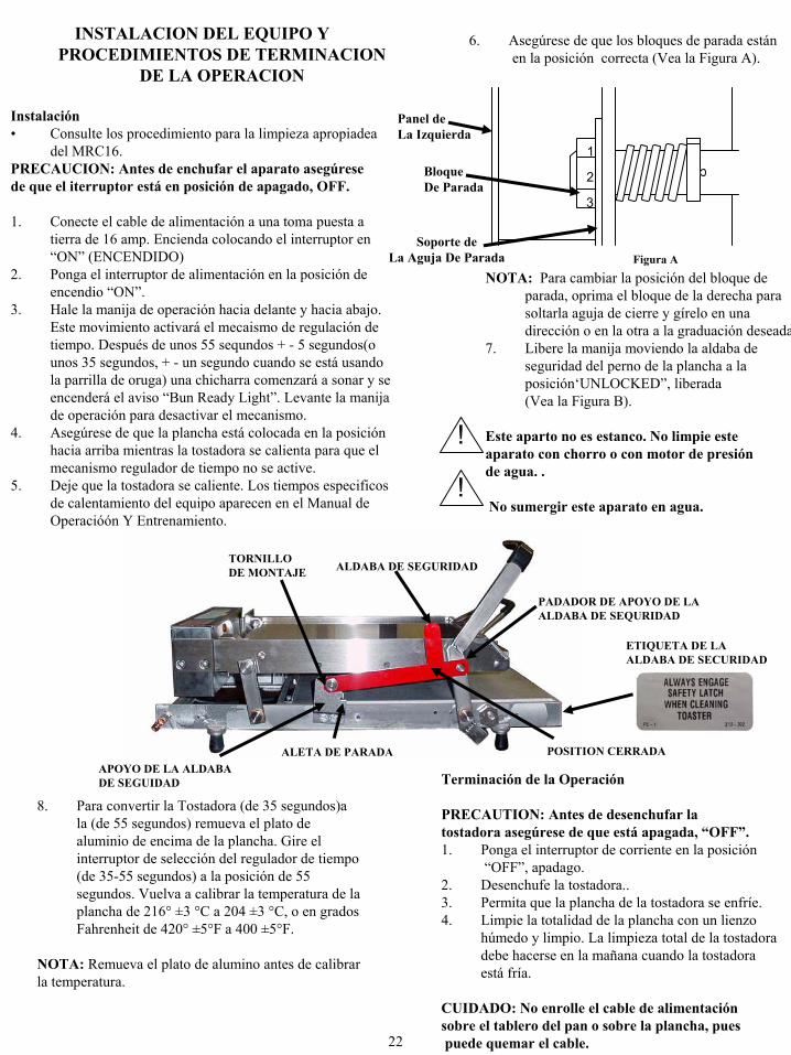
INSTALACION DEL EQUIPO Y PROCEDIMIENTOS DE TERMINACION
DE LA OPERACION
Instalación• Consulte los procedimiento para la limpieza apropiadea
del MRC16.PRECAUCION: Antes de enchufar el aparato asegúresede que el iterruptor está en posición de apagado, OFF.
1. Conecte el cable de alimentación a una toma puesta a tierra de 16 amp. Encienda colocando el interruptor en “ON” (ENCENDIDO)
2. Ponga el interruptor de alimentación en la posición de encendio “ON”.
3. Hale la manija de operación hacia delante y hacia abajo. Este movimiento activará el mecaismo de regulación de tiempo. Después de unos 55 sequndos + - 5 segundos(ounos 35 segundos, + - un segundo cuando se está usandola parrilla de oruga) una chicharra comenzará a sonar y se encenderá el aviso “Bun Ready Light”. Levante la manijade operación para desactivar el mecanismo.
4. Asegúrese de que la plancha está colocada en la posiciónhacia arriba mientras la tostadora se calienta para que el mecanismo regulador de tiempo no se active.
5. Deje que la tostadora se caliente. Los tiempos especificosde calentamiento del equipo aparecen en el Manual de Operacióón Y Entrenamiento.
6. Asegúrese de que los bloques de parada estánen la posición correcta (Vea la Figura A).
NOTA: Para cambiar la posición del bloque de parada, oprima el bloque de la derecha parasoltarla aguja de cierre y gírelo en unadirección o en la otra a la graduación deseada
7. Libere la manija moviendo la aldaba deseguridad del perno de la plancha a la posición‘UNLOCKED”, liberada(Vea la Figura B).
Este aparto no es estanco. No limpie esteaparato con chorro o con motor de presiónde agua. .
No sumergir este aparato en agua.
!
!
8. Para convertir la Tostadora (de 35 segundos)ala (de 55 segundos) remueva el plato de aluminio de encima de la plancha. Gire el interruptor de selección del regulador de tiempo(de 35-55 segundos) a la posición de 55 segundos. Vuelva a calibrar la temperatura de la plancha de 216° ±3 °C a 204 ±3 °C, o en gradosFahrenheit de 420° ±5°F a 400 ±5°F.
NOTA: Remueva el plato de alumino antes de calibrarla temperatura.
Terminación de la Operación
PRECAUTION: Antes de desenchufar la tostadora asegúrese de que está apagada, “OFF”.1. Ponga el interruptor de corriente en la posición
“OFF”, apadago. 2. Desenchufe la tostadora.. 3. Permita que la plancha de la tostadora se enfríe. 4. Limpie la totalidad de la plancha con un lienzo
húmedo y limpio. La limpieza total de la tostadoradebe hacerse en la mañana cuando la tostadoraestá fría.
CUIDADO: No enrolle el cable de alimentaciónsobre el tablero del pan o sobre la plancha, puespuede quemar el cable. 22
1
2
3
Panel deLa Izquierda
BloqueDe Parada
Soporte deLa Aguja De Parada
TORNILLO DE MONTAJE ALDABA DE SEGURIDAD
PADADOR DE APOYO DE LAALDABA DE SEQURIDAD
ALETA DE PARADAAPOYO DE LA ALDABA DE SEGUIDAD
POSITION CERRADA
ETIQUETA DE LA ALDABA DE SECURIDAD
Figura A

GUIA PARA LA RESOLUCION DE PROBLEMAS
NOTA: El trabajo en esta máquina debe ser hechopor personal calificado.
PRECAUCION: La inspección, prueba y reparacióndel equipo elétrico deben ser hechos únicamentepor pesonal calificado de mantenimiento. La unidaddebe desenchufarse cuando se va a trabajar en ella
excepto cuando sea necesasrio hacer pruebaso mediciones eléctricas.
PELIGRO: Use extremo cuidado en la ejecuciónde prebas de los circuitos eléctricos. Ciertoscircuitos electrificados quedarán al descubierto.
Cambie el tablero de loc panecillos. Pieza #35. Se está usando un tablero inaprpiado paralos panecillos.
Reemplace el plato. El plato de aluminio no se está usandopara las tostadas de 35 segundos.
El segmento inferior de lospanecillos no se tuestasuficientemente en los 35 or 55 segundos.
Verifique la posición del interruptor de seleccióndel regulador de tiempo. Colóquelo en 55 segundos. Verifique el tiempo.
El regulador de tiempo se ha fijadoincorrectamente.
El dispositivo de control de tiemp suena a los 35 segundosen lugar de hacerlo a los 55 segundos.
Limpie la plancha. See 16.Se ha acumulado azúcar en la plancha.
Vuelva a calibrar el termostato. Vea MRC 16. El calor es excesivo. Los panecillos se pegan a lo plancha.
Reemplace la plancha. Llame a la agencia de mantenimiento.
La plancha se ha quemado o ha hechocorto circuito. .
Reemplace el termostato. El termostato no funciona.
Conecte apropiadamente los cables sueltos. VeaMRC 17.
Hay cables sueltos.
Reemplace el interruptor de alimentación. El interruptor de alimentación no funciona.
Revise la fuente de alimentación. No hay corriente. La plancha no calienta.
Enderece o reemplace la plataforma de lospanecillos.
La plataforma de los panecillos estácombada.
Advise a la panadería. Los panecillos no se han cortadoapropiadamente.
Enderece o reemplace las bandejas de lospanecillos.
Las bandejas de los panecillos estántorcidas.
Ajuste los bloques de parada. Los bloques de parada no se han ajustadocorrectamente.
Los panecillos quedanmaltratados.
Reemplace la chicharra. La chicharra se ha quemado. La luz ámbar de “Bun Ready”se enciende pero la chicharra no suena.
Ajuste el recorrido del interruptordel regulador de tiempo.
El interruptor del regulador de tiempo estádesajustado.
Reemplace el dipositivo de regulación de tiempo.El ensamble del regulador de tiempo no funciona.
Reemplace el interruptor del regulador de tiempo. El interruptor del regulador de tiempo no funciona.
No suena la chicharra ni se enciende la luz “Bun Ready”.
Reemplace la luz. La luz se ha quemado. La chcharra suena, pero no se enciende la luz de “Bun Done”.
Apriete los tonillos de la plancha. Vea MRC 16.Los tornillos de la plancha están sueltos. Plancha suelta
ACCION CORRECTIVACAUSA PROBABLEPROBLEMA

MANTENIMIENTO NO PROGRAMADO
En condiciones normales y con uso y limpiezaapropiados, esta tostadora requiere muy pocomantenimiento no programado. Sin embargo, en estasección se presentan los procedimientos para probary reemplazar las divesas partes de la tostadora en caso de que sea necesario. Antes de reemplazarcualquier parte consulte la sección de Resolución de Probelmas que puede ayudarle a determinar la causade cualquier defecto de funcionamiento.
INSTRUCCIONES GENERALES
!Se deberá reemplazar el cable de alimentaciónpor un cable de caucho a prueba de aceite y de una capacidad de disipación térmica de por lo menos 90°C.
REPARACIONES ELECTRICAS EL COLOCAR EL INTERRUPTOR DE CORREIENTE EN LA POSICION “OFF”, APAGADO, Y DESENCHUFAR LA TOASTADORA ES UN PROCEDIMIENTO ESTANDAR PARA CUALQUIER REPARACION ELECTRICA.
Cuando vaya a reemplazar cualquier control eléctricomontado en la caja de control, las siguentes operacionesson procedimiento estándar (excepto donde se indique lo contrario)Remueva los 2 tornillos de la cubierta de la caja eléctrica. A. Remueva la cubierta. B. Remeuva los 6 tornillos de la platina del frente.
REEMPLAZO DE LA PLANCHA Este procedimiento debe ser realizado por personalcalificado de mantenimiento.
REEMPLAZO DE LAS LUCES. 1. Ubique la luz que no está operando. 2. Desconecte los dos alambres de la luz. 3. Remueva la luz oprimiendo los granchos de bisel
mientras saca la luz del panel de control. 4. Realice el procedimiento a la inversa para
instalar la luz nueva.
REEMPLAZO DEL INTERRUPTOR DE ALIMENTACIONHerramientas: Destornillador de hoja plana.
1. Ponga el interruptor de corriente en “OFF”, apagado, y desenchufe la tostadora.
PRECAUCION: El no hacerio puede causarle unadescarge eléctrica. 2. Retire el interruptor de alimentación apretando los
clips Bozel del interruptor y empujando éste parasacarlo de la caja de control.
3. Retire los cables del interruptor. Vea el diagramade cableado para las conexiones elécricas.
4. Invierta el orden de los pasos para colocar de nuevo.
REEMPLACE EL CABLE DE ALIMNATICAION Herramientas: Un destronillador de hoja plana.
1. Ponga el interruptor de corriente en “OFF”, apagado,y desenchufe la toastadora.
PRECAUCION: El no hacerlo puede causarle unadescarge eléctrica. .2. Tendrá que remover el interruptor de corriente para
llegar al almbre o alambres del cable de alimnentaciónconectados al termincal de abajo.
24
Cuando desconecte cualquier cable eléctrico márqueloen alguna forma que le indique a que terminal vaconectado. No desconecte muchas conexiones eléctricasal mismo tiempo. En caso de que olvide a donde vaconectado un cable, consulte el diagrama eléctrico del dispositivoque está reparando.
Sequramente notará que hay tres métodos básicos de conectar los alambres a sus terminales: (1) ojal;( 2) horquilla; (3) cuchilla
NUNCA ENROLLE UN ALAMBRE DESNUDO BAJO LA TUERCA DEL TERMINAL. USE LAS CONEXIONES APROPIADAS. .
Antes de comenzar la reparación de la tostadora, usted debe: A. Girar el interruptor a la posición “OFF”, apagado, y
desenchufar la tostador. B. Desconnectar el suministro de corriente.
PRECAUCION: El no sequir esta instrucionespuede causarle ena descarga eléctrica .
C. Permita que la unidad se enfríe completamente. Por último: Examine cuidadosamente los diagramasde “Vista de Explosión y las fotografías de estecapítulo que le permitrián entender la configuraciónfísica de su tostadora y la forma de reensamblarsus componentes.

3. Desconecte de la platina frontal el alambreverde/amarillo de conexión a tierra.
4. Desconecte del interruptor de corriente el alambremarrón.
5. Desconecte de encima del interruptor de corriente el alambre azul neutro, en las unidades de 115 voltios.En las unidades de 200/220 voltios, desconecte de la
parte de abajo del interruptor de corriente el alambre neutro azul.
6. Remueva el cable de la platine fronta sacando el bujede protección contra tensión (contra tirones).
7. Siga el procedimiento a la inversa para volver a colocar el cabl de alimentación
REEMPLAZO DE LA CHICHARRA(Vea la Figura 4)
Herramientas: Un destronillado de hoja plana.
1. Ponga el interruptor de corriente en “OFF”, apagado, y desenchufe la tostadora.
PRECAUCION: El no hacerlo puede causarle unadescarga eléctrica.
2. Remueva el tornillo que sujeta la chicarra a la platina frontal.
3. Corte los dos alambres de la chicharra. 4. Quite la aislación en unos 13 mm (1/2”) de los
extremos de los alambres que acaba de cortar.5. Conecte le nueva chicharra con tuercas para alambre.
REEMPLAZO DEL TERMOSTATO(Vea la Figura 4)
Herramientas: Un destronillador de hoja plana.
1. Ponga el interruptor de corriente in “OFF”, apagado, y desenchufe la tostadora.
PRECAUCION: El no haccerlo puede causarleuna descarga eléctrica.
2. Remueva la perilla aflojando el peque o ornillo de ajuste en la perrilla.
3. Remueva los 2 tornillos que sujetan el termostato y la platina de graduación a la platina frontal.
4. Remueva los 2 alambres de los terminalesdel termostato.
5. Remueva de la caja eléctrica el retendeor de la bombilla del termostato.
6. Remueva el termostato y la bombilla del sensor.7. Coloque el nuevo termostato siguiendo este
procedimiento a la inversa y asegurándose de aplicar a la bombilla der termostato el material témico que se suminstra con él.
8. Calibre el termostato en la forma descrita en la Tarjeta No. 16 de Mantenimiento Planificado. .
REEMPLAZO DEL INTERRUPTOR DEL REGULADOR DE TIEMPO(Vea la Figuras 2 & 4)
Herramientas: Un destornillador de hoja plana.
1. Ponga el interruptor de corriente en “OFF”, apagado, y desenchufe la tostadora.
PRECAUCION: El no hacerlo puede causarleuna descarge eléctrica. .2. Remeuva del exterior de la caja eléctrica
la tuerca de retencion.3. Remueva de la caja eléctrica el interruptor. 4. Remueva del interruptor el anillo de retención
y el aislador. 5. Remueva los 2 alambres del interruptor. 6. Coloque los 2 alambres en el nuevo interruptor. 7. Inserte el nuevo interruptor en el aislador. 8. Coloque el anillo de retención en el nuevo
interruptor a 6 mm del extremo del buje.
NOTA: El aislador debe colocarse entre el mecanismodel interruptor y el anillo de retención(Vea la Figura 2).
25

9. Instale el nuevo interruptor en la caja eléctricay apriete la tuerca de retención en el exterio de la caja eléctrica.
10. Coloque los bloques de parada en su posiciónmás baja.
11. Baje lentamente la plancha y examine el movimiento del nuevo interruptor contra el soporte del acutador.
NOTA: Cuando la plancha ha llegado a su punto másabjo debe haber una distancia no mayor de 1 mm entre el buje roscado del interruptor y el soporte del actuador.
NOTA: El buje roscado del interruptor no debequedar tocando el soporte del actuador.
12. Para ajustar el soporte del actuador afloje lostornillos de montaje y mueva el soporte hastaobtener la distancia de 1 mm (1/32”) como se muestra en la Figura 3 de abajo. Apriete los tornillosde mantaje una vez que el apoyo se ha colocadocorrectamente.
13. Apriete la tuerca de retención contra el chasis paraevitar el movimiento.
REEMPLAZO DEL ENSAMBLE DEL REGULADOR DE TIEMPO(Vea la Figura 4)
Herramientas: Un destornillador de hojaplanna.
1. Ponga el interruptor de corriente en “OFF”, apagado, y desenchufe la toastadora.
PRECAUCION: El no hacerlo puedecausarle una descarge eléctrica
2. Remueva los 2 alambres del ensamble del regulador de tiempo.
3. el ensamble en el fondo de la caja eléctrica4. Remueva el ensamble. 5. Reemplácelo con un nuevo ensamble de
regulador de tiempo siguiendo el procedimiento a la inversa.
26
6 mm (1/4”)
TUERCA DERETENCION
CAJAELECTRICA ANILLO DE
RETENTION
AISLADOR
MECANISMO DELINTERRUPTOR
Figura 2
SOPORTE DELACTUADOR
MARCO
TORNILLOS DE MONTAJE
CAJAELECTRICA
BUJE ROSCADODEL INTERRUPTOR
AISLADOR
INTERRUPTORDEL REGULADOR
DE TIEMPOENSAMBLE DELREGULADORDE TIEMPO
CHICHARRA TERMOSTATO
Figura 4

27

28