Embed Size (px)
Citation preview
Dell™ Inspiron™ 7500 System
REFERENCE AND TROUBLESHOOTING GUIDE
BE DIRECT
www.dell.com
™
™
Notes, Notices, and CautionsThroughout this guide, blocks of text may be accompanied by an icon and printed in bold type or in italic type. These blocks are notes, notices, and cautions, and they are used as follows:
NOTE: A NOTE indicates important information that helps you make better use of your computer system.
NOTICE: A NOTICE indicates either potential damage to hardware or loss of data and tells you how to avoid the problem.
CAUTION: A CAUTION indicates a potentially hazardous situation which, if not avoided, may result in minor or moderate injury.
____________________
Information in this document is subject to change without notice.© 1999 Dell Computer Corporation. All rights reserved.
Reproduction in any manner whatsoever without the written permission of Dell Computer Corporation is strictly forbidden.
Trademarks used in this text: Dell, the DELL logo, Inspiron, and MegaBay are trademarks and DellWare is a service mark of Dell Computer Corporation; Microsoft, MS-DOS, Windows, and Windows NT are registered trademarks of Microsoft Corporation; Intel is a registered trademark of Intel Corporation.
Other trademarks and trade names may be used in this document to refer to either the entities claiming the marks and names or their products. Dell Computer Corporation disclaims any proprietary interest in trademarks and trade names other than its own.
September 1999 P/N 6945T Rev. A00
v
Safety Instructions
As you use your computer, observe the following safety guidelines:
• Do not attempt to service the computer yourself. Always follow installation instructions closely.
• Do not carry a battery pack in your pocket, purse, or other container where metal objects (such as car keys) could short-circuit the battery terminals. The resulting excessive current flow can cause extremely high temperatures and may result in damage from burns.
• Be sure that nothing rests on your AC adapter’s power cable and that the cable is not located where it can be tripped over or stepped on.
• Place the AC adapter in a ventilated area, such as a desk top or on the floor, when you use it to run the computer or to charge the battery. Do not cover the AC adapter with papers or other items that will reduce cooling; also, do not use the AC adapter inside a carrying case.
• Do not use your computer in a wet environment, for example, near a bathtub, sink, or swimming pool or in a wet basement.
• Do not push objects into air vents or openings of your computer. Doing so can cause fire or electric shock by shorting out interior components.
• Use only the AC adapter and batteries that are approved for use with this computer as indicated in this document. Use of another type of battery pack or AC adapter may risk fire or explosion.
• Before you connect the computer to a power source, ensure that the voltage rating of the AC adapter matches that of the available power source:
— 115 volts (V)/60 hertz (Hz) in most of North and South America and some Far Eastern countries such as South Korea and Taiwan
— 100 V/50 Hz in eastern Japan and 100 V/60 Hz in western Japan
— 230 V/50 Hz in most of Europe, the Middle East, and the Far East
• To help prevent electric shock, plug the AC adapter and peripheral power cables into properly grounded power sources. These cables are equipped with 3-prong plugs to help ensure proper grounding. Do not use adapter plugs or remove the grounding prong from a cable. If you must use an extension cable, use a 3-wire cable with properly grounded plugs.

vi
• If you use an extension cable with your AC adapter, ensure that the total ampere rating of the products plugged in to the extension cable does not exceed the ampere rating of the extension cable.
• To remove power from the computer, turn it off, remove the battery pack, and disconnect the AC adapter from the electrical outlet.
• If your computer includes an integrated or optional (PC Card) modem, disconnect the modem cable during an electrical storm to avoid the remote risk of electric shock from lightning via the telephone line.
• To help avoid the potential hazard of electric shock, do not connect or disconnect any cables or perform maintenance or reconfiguration of this product during an electrical storm.
• PC Cards may become very warm during normal operation. Use care when removing PC Cards after their continuous operation.
• Do not dispose of battery packs in a fire. They may explode. Check with local authorities for disposal instructions.
• When traveling, do not check the computer as baggage. You can put your computer through an X-ray security machine, but never put your computer through a metal detector. If you have the computer checked by hand, be sure to have a charged battery available in case you are asked to turn on the computer.
• When traveling with the hard-disk drive removed from the computer, wrap the drive in a nonconducting material, such as cloth or paper. If you have the drive checked by hand, be ready to install the drive in the computer. You can put the hard-disk drive through an X-ray security machine, but never put the drive through a metal detector.
• When traveling, do not place the computer in overhead storage compartments where it could slide around. Do not drop your computer or subject it to other mechanical shocks.
• Protect your computer, battery, and hard-disk drive from environmental hazards such as dirt, dust, food, liquids, temperature extremes, and overexposure to sunlight.
• When you move your computer between environments with very different temperature and/or humidity ranges, condensation may form on or within the computer. To avoid damaging the computer, allow sufficient time for the moisture to evaporate before using the computer.
NOTICE: When taking the computer from low-temperature conditions into a warmer environment or from high-temperature conditions into a cooler environment, allow the computer to acclimate to room temperature before turning on power.
vii
• When you disconnect a cable, pull on its connector or on its strain-relief loop, not on the cable itself. As you pull out the connector, keep it evenly aligned to avoid bending any connector pins. Also, before you connect a cable make sure both connectors are correctly oriented and aligned.
• Handle components with care. Hold a component such as a memory module by its edges, not its pins.
• When removing a memory module from the system board or disconnecting a peripheral device from the computer, wait 5 seconds after turning off the computer before removing the memory module or disconnecting the device to help avoid possible damage to the system board.
• Before you clean your computer, turn it off, unplug it from its power source, and remove the battery pack(s).
• Clean your computer and display with a soft cloth dampened with water rather than with liquid or aerosol cleaners.
• If your computer gets wet or is damaged, follow the procedures described in Chapter 3, “Basic Troubleshooting.” If, after following these procedures, you confirm that your computer is not operating properly, contact Dell Computer Corporation. (See Chapter 5, “Getting Help,” for the appropriate telephone number.)
Ergonomic Computing Habits CAUTION: Improper or prolonged keyboard use may result in injury.
CAUTION: Viewing the display or external monitor screen for extended periods of time may result in eye strain.
viii
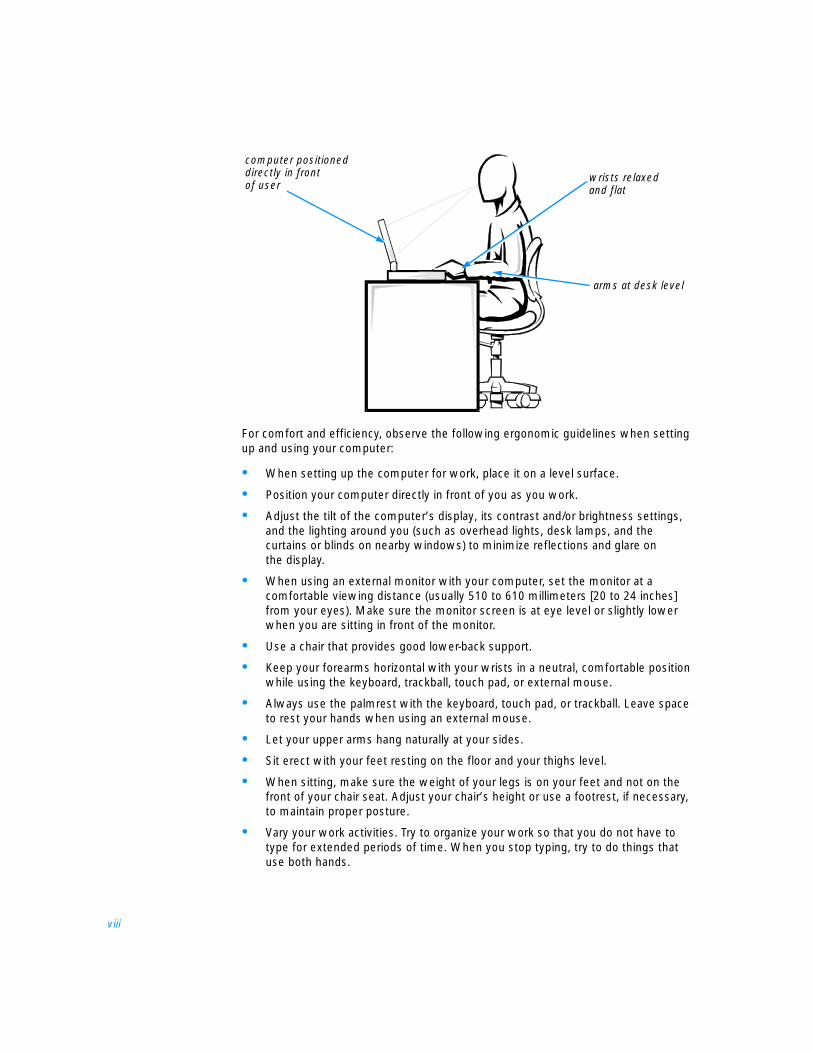
For comfort and efficiency, observe the following ergonomic guidelines when setting up and using your computer:
• When setting up the computer for work, place it on a level surface.
• Position your computer directly in front of you as you work.
• Adjust the tilt of the computer’s display, its contrast and/or brightness settings, and the lighting around you (such as overhead lights, desk lamps, and the curtains or blinds on nearby windows) to minimize reflections and glare on the display.
• When using an external monitor with your computer, set the monitor at a comfortable viewing distance (usually 510 to 610 millimeters [20 to 24 inches] from your eyes). Make sure the monitor screen is at eye level or slightly lower when you are sitting in front of the monitor.
• Use a chair that provides good lower-back support.
• Keep your forearms horizontal with your wrists in a neutral, comfortable position while using the keyboard, trackball, touch pad, or external mouse.
• Always use the palmrest with the keyboard, touch pad, or trackball. Leave space to rest your hands when using an external mouse.
• Let your upper arms hang naturally at your sides.
• Sit erect with your feet resting on the floor and your thighs level.
• When sitting, make sure the weight of your legs is on your feet and not on the front of your chair seat. Adjust your chair’s height or use a footrest, if necessary, to maintain proper posture.
• Vary your work activities. Try to organize your work so that you do not have to type for extended periods of time. When you stop typing, try to do things that use both hands.
arms at desk level
computer positioned directly in front of user
wrists relaxed and flat
ix
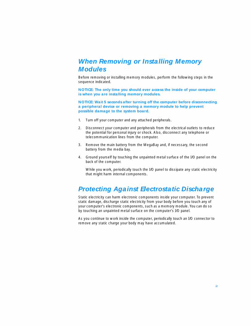
When Removing or Installing Memory Modules Before removing or installing memory modules, perform the following steps in the sequence indicated.
NOTICE: The only time you should ever access the inside of your computer is when you are installing memory modules.
NOTICE: Wait 5 seconds after turning off the computer before disconnecting a peripheral device or removing a memory module to help prevent possible damage to the system board.
1. Turn off your computer and any attached peripherals.
2. Disconnect your computer and peripherals from the electrical outlets to reduce the potential for personal injury or shock. Also, disconnect any telephone or telecommunication lines from the computer.
3. Remove the main battery from the MegaBay and, if necessary, the second battery from the media bay.
4. Ground yourself by touching the unpainted metal surface of the I/O panel on the back of the computer.
While you work, periodically touch the I/O panel to dissipate any static electricity that might harm internal components.
Protecting Against Electrostatic Discharge Static electricity can harm electronic components inside your computer. To prevent static damage, discharge static electricity from your body before you touch any of your computer’s electronic components, such as a memory module. You can do so by touching an unpainted metal surface on the computer’s I/O panel.
As you continue to work inside the computer, periodically touch an I/O connector to remove any static charge your body may have accumulated.
x
You can also take the following steps to prevent damage from electrostatic discharge (ESD):
• When unpacking a static-sensitive component from its shipping carton, do not remove the component from the antistatic packing material until you are ready to install the component. Just before unwrapping the antistatic packaging, be sure to discharge static electricity from your body.
• When transporting a sensitive component, first place it in an antistatic container or packaging.
• Handle all sensitive components in a static-safe area. If possible, use antistatic floor pads and workbench pads.
The following notice may appear throughout this document to remind you of these precautions:
NOTICE: See “Protecting Against Electrostatic Discharge” in the safety instructions at the front of this guide.
xi
Preface
About This GuideThis guide is intended for anyone who uses a Dell portable computer. It can be used by both first-time and experienced computer users who want to learn about the features of the computer. This guide also provides basic troubleshooting procedures and instructions for using the Dell Diagnostics to test your computer and its components.
Summaries of the chapters and appendixes of this guide follow:
• Chapter 1, “Introduction,” provides an overview of the computer features and a list of available upgrades.
• Chapter 2, “Options and Upgrades,” describes the installation procedures for the options and upgrades available from Dell for your computer.
• Read Chapter 3, “Basic Troubleshooting,” for some initial checks and procedures that you can use to solve basic computer problems and for some general guidelines on analyzing software problems.
• Chapter 4, “Installing System Software,” provides detailed instructions for reinstalling system drivers and software.
• Chapter 5, “Getting Help,” describes the help tools Dell provides to assist you if you have a problem with the computer. It also explains how and when to call Dell for technical assistance.
• Appendix A, “Technical Specifications,” is intended primarily as reference material if you are interested in learning more about the details of your computer.
• Read Appendix B, “Using the Setup Program,” to learn how to access the Setup program, which allows you to change system settings, such as your computer’s power conservation features.
• Appendix C, “System Messages and Beep Codes,” defines system messages and beep codes.
• Appendix D, “Regulatory Notices,” is for users who are interested in which regulatory agencies have tested and approved your computer.
• Appendix E, “Warranty, Return Policy, and Year 2000 Statement of Compliance,” describes the warranty for your Dell computer, the “Total Satisfaction” Return Policy, and the year 2000 compliance of Dell-branded hardware products.
xii
Warranty and Return Policy InformationDell Computer Corporation (“Dell”) manufactures its hardware products from parts and components that are new or equivalent to new in accordance with industry-standard practices.
For information about the Dell warranty and return policy, see Appendix E, “Warranty, Return Policy, and Year 2000 Statement of Compliance.”
Other Documents You May NeedIn addition to this Reference and Troubleshooting Guide, the following documentation is included with your computer:
• The Setup Guide provides instructions for setting up a Dell Inspiron computer and for using your computer’s hardware.
• The system Help contains essential information you need to use your computer.
To open the Help, click the Start button, point to Programs—> Dell Documents, and click Dell Inspiron 7500 System Help.
You may also have one or more of the following documents:
• Information updates describing changes to your computer or software.
NOTE: Always read any included update before consulting any other documentation because the updates contain the latest information.
• Operating system documentation is included if Dell installed the operating system on your hard-disk drive. This documentation describes how to configure and use your operating system software.
Notational ConventionsThe following subsections list notational conventions used in this document.
Notes, Notices, and CautionsThroughout this guide, blocks of text may be accompanied by an icon and printed in bold type or in italic type. These blocks are notes, notices, and cautions, and they are used as follows:
NOTE: A NOTE indicates important information that helps you make better use of your computer system.
NOTICE: A NOTICE indicates either potential damage to hardware or loss of data and tells you how to avoid the problem.
CAUTION: A CAUTION indicates a potentially hazardous situation which, if not avoided, may result in minor or moderate injury.
xiii
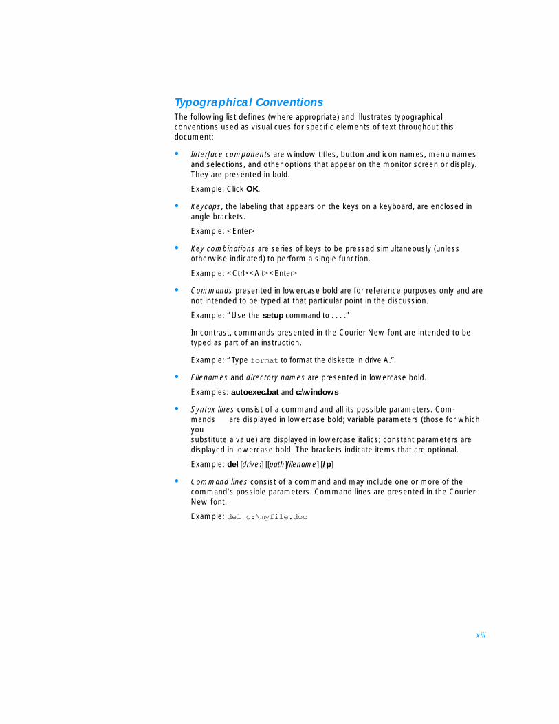
Typographical ConventionsThe following list defines (where appropriate) and illustrates typographical conventions used as visual cues for specific elements of text throughout this document:
• Interface components are window titles, button and icon names, menu names and selections, and other options that appear on the monitor screen or display. They are presented in bold.
Example: Click OK.
• Keycaps, the labeling that appears on the keys on a keyboard, are enclosed in angle brackets.
Example: <Enter>
• Key combinations are series of keys to be pressed simultaneously (unless otherwise indicated) to perform a single function.
Example: <Ctrl><Alt><Enter>
• Commands presented in lowercase bold are for reference purposes only and are not intended to be typed at that particular point in the discussion.
Example: “Use the setup command to . . . .”
In contrast, commands presented in the Courier New font are intended to be typed as part of an instruction.
Example: “Type format to format the diskette in drive A.”
• Filenames and directory names are presented in lowercase bold.
Examples: autoexec.bat and c:\windows
• Syntax lines consist of a command and all its possible parameters. Com-mands are displayed in lowercase bold; variable parameters (those for which you substitute a value) are displayed in lowercase italics; constant parameters are displayed in lowercase bold. The brackets indicate items that are optional.
Example: del [drive:] [[path]filename] [/p]
• Command lines consist of a command and may include one or more of the command’s possible parameters. Command lines are presented in the Courier New font.
Example: del c:\myfile.doc
xiv
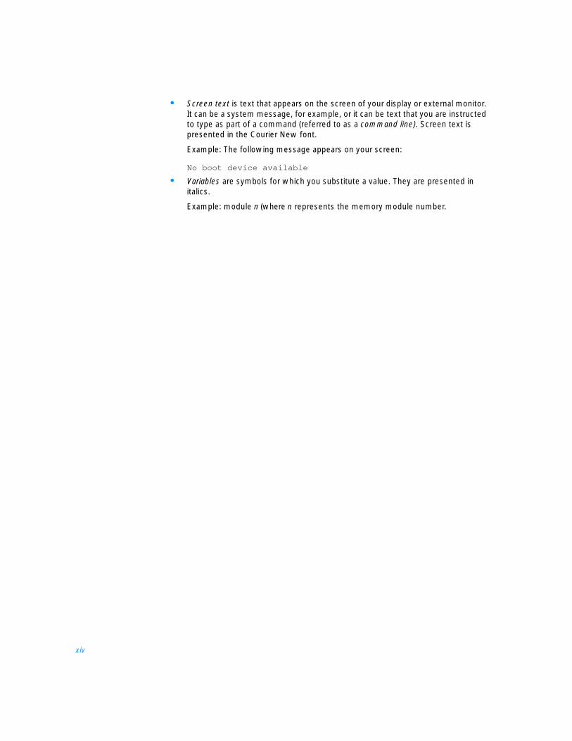
• Screen text is text that appears on the screen of your display or external monitor. It can be a system message, for example, or it can be text that you are instructed to type as part of a command (referred to as a command line). Screen text is presented in the Courier New font.
Example: The following message appears on your screen:
No boot device available
• Variables are symbols for which you substitute a value. They are presented in italics.
Example: module n (where n represents the memory module number.

xv
Contents
Chapter 1 Introduction. . . . . . . . . . . . . . . . . . . . . . . . . . . . . . . . . 1-1Hardware Features . . . . . . . . . . . . . . . . . . . . . . . . . . . . . . . . . . . . . . . . . . . . . . . . . 1-1
Front View of the Computer. . . . . . . . . . . . . . . . . . . . . . . . . . . . . . . . . . . . . . . 1-3Back View of the Computer . . . . . . . . . . . . . . . . . . . . . . . . . . . . . . . . . . . . . . . 1-5
Software Features . . . . . . . . . . . . . . . . . . . . . . . . . . . . . . . . . . . . . . . . . . . . . . . . . . 1-7Available Options and Upgrades . . . . . . . . . . . . . . . . . . . . . . . . . . . . . . . . . . . . . . . 1-7Getting Help . . . . . . . . . . . . . . . . . . . . . . . . . . . . . . . . . . . . . . . . . . . . . . . . . . . . . . 1-8
Chapter 2 Options and Upgrades . . . . . . . . . . . . . . . . . . . . . . . . 2-1Using the AC Adapter . . . . . . . . . . . . . . . . . . . . . . . . . . . . . . . . . . . . . . . . . . . . . . . 2-1Using the Media Bay . . . . . . . . . . . . . . . . . . . . . . . . . . . . . . . . . . . . . . . . . . . . . . . . 2-2Using the MegaBay . . . . . . . . . . . . . . . . . . . . . . . . . . . . . . . . . . . . . . . . . . . . . . . . . 2-3Installing a Battery . . . . . . . . . . . . . . . . . . . . . . . . . . . . . . . . . . . . . . . . . . . . . . . . . . 2-5Attaching the Composite TV-Out Adapter Cable . . . . . . . . . . . . . . . . . . . . . . . . . . . 2-6Installing an Internal Hard-Disk Drive. . . . . . . . . . . . . . . . . . . . . . . . . . . . . . . . . . . . 2-7
Returning a Hard-Disk Drive to Dell . . . . . . . . . . . . . . . . . . . . . . . . . . . . . . . . . 2-9Installing Memory Modules. . . . . . . . . . . . . . . . . . . . . . . . . . . . . . . . . . . . . . . . . . . 2-9
Creating the Save-to-Disk Suspend File . . . . . . . . . . . . . . . . . . . . . . . . . . . . . 2-12Port Replicator . . . . . . . . . . . . . . . . . . . . . . . . . . . . . . . . . . . . . . . . . . . . . . . . . . . . 2-13Connecting Other External Devices . . . . . . . . . . . . . . . . . . . . . . . . . . . . . . . . . . . 2-13
Chapter 3 Basic Troubleshooting. . . . . . . . . . . . . . . . . . . . . . . . . 3-1Checking the Basics . . . . . . . . . . . . . . . . . . . . . . . . . . . . . . . . . . . . . . . . . . . . . . . . 3-1
Checking Connections . . . . . . . . . . . . . . . . . . . . . . . . . . . . . . . . . . . . . . . . . . . 3-2Environmental Factors . . . . . . . . . . . . . . . . . . . . . . . . . . . . . . . . . . . . . . . . . . . 3-3Power . . . . . . . . . . . . . . . . . . . . . . . . . . . . . . . . . . . . . . . . . . . . . . . . . . . . . . . . 3-3Modem. . . . . . . . . . . . . . . . . . . . . . . . . . . . . . . . . . . . . . . . . . . . . . . . . . . . . . . 3-4Drives . . . . . . . . . . . . . . . . . . . . . . . . . . . . . . . . . . . . . . . . . . . . . . . . . . . . . . . . 3-4
Cleaning Diskette Drives. . . . . . . . . . . . . . . . . . . . . . . . . . . . . . . . . . . . . . 3-5
xvi
Look and Listen. . . . . . . . . . . . . . . . . . . . . . . . . . . . . . . . . . . . . . . . . . . . . . . . . . . . 3-5Setup Options . . . . . . . . . . . . . . . . . . . . . . . . . . . . . . . . . . . . . . . . . . . . . . . . . 3-6
Finding Software Solutions . . . . . . . . . . . . . . . . . . . . . . . . . . . . . . . . . . . . . . . . . . . 3-7Installing and Configuring Software . . . . . . . . . . . . . . . . . . . . . . . . . . . . . . . . . 3-7
Start-Up Files . . . . . . . . . . . . . . . . . . . . . . . . . . . . . . . . . . . . . . . . . . . . . . 3-8Using Software . . . . . . . . . . . . . . . . . . . . . . . . . . . . . . . . . . . . . . . . . . . . . . . . 3-8
Error Messages . . . . . . . . . . . . . . . . . . . . . . . . . . . . . . . . . . . . . . . . . . . . 3-8Input Errors . . . . . . . . . . . . . . . . . . . . . . . . . . . . . . . . . . . . . . . . . . . . . . . . 3-8Memory-Resident Programs. . . . . . . . . . . . . . . . . . . . . . . . . . . . . . . . . . . 3-8Program Conflicts . . . . . . . . . . . . . . . . . . . . . . . . . . . . . . . . . . . . . . . . . . . 3-9Avoiding Interrupt Assignment Conflicts . . . . . . . . . . . . . . . . . . . . . . . . . 3-9
Troubleshooting Procedures . . . . . . . . . . . . . . . . . . . . . . . . . . . . . . . . . . . . . . . . . 3-10Troubleshooting a Wet Computer . . . . . . . . . . . . . . . . . . . . . . . . . . . . . . . . . 3-10Troubleshooting a Damaged Computer . . . . . . . . . . . . . . . . . . . . . . . . . . . . . 3-12Troubleshooting a Power Failure . . . . . . . . . . . . . . . . . . . . . . . . . . . . . . . . . . 3-13
Total Power Failure When Using the AC Adapter. . . . . . . . . . . . . . . . . . 3-14Total Power Failure When Using a Battery. . . . . . . . . . . . . . . . . . . . . . . 3-14No Power to a Part of the Computer . . . . . . . . . . . . . . . . . . . . . . . . . . . 3-16
Troubleshooting the Diskette Drive . . . . . . . . . . . . . . . . . . . . . . . . . . . . . . . . 3-16Troubleshooting the CD-ROM or DVD-ROM Drive . . . . . . . . . . . . . . . . . . . . 3-17Troubleshooting the Hard-Disk Drive . . . . . . . . . . . . . . . . . . . . . . . . . . . . . . . 3-18Troubleshooting an External Keyboard . . . . . . . . . . . . . . . . . . . . . . . . . . . . . 3-20Troubleshooting Memory. . . . . . . . . . . . . . . . . . . . . . . . . . . . . . . . . . . . . . . . 3-21Troubleshooting the Display . . . . . . . . . . . . . . . . . . . . . . . . . . . . . . . . . . . . . 3-22Troubleshooting an External Monitor. . . . . . . . . . . . . . . . . . . . . . . . . . . . . . . 3-23Troubleshooting the Serial and Parallel Ports. . . . . . . . . . . . . . . . . . . . . . . . . 3-25
Troubleshooting the Basic I/O Functions . . . . . . . . . . . . . . . . . . . . . . . . 3-25Troubleshooting a Parallel Printer . . . . . . . . . . . . . . . . . . . . . . . . . . . . . . 3-26Troubleshooting a Serial I/O Device . . . . . . . . . . . . . . . . . . . . . . . . . . . . 3-27Troubleshooting the Infrared Port. . . . . . . . . . . . . . . . . . . . . . . . . . . . . . 3-28
Troubleshooting the Touch Pad . . . . . . . . . . . . . . . . . . . . . . . . . . . . . . . . . . . 3-28Troubleshooting Audio Functions . . . . . . . . . . . . . . . . . . . . . . . . . . . . . . . . . 3-29
Running the Dell Diagnostics . . . . . . . . . . . . . . . . . . . . . . . . . . . . . . . . . . . . . . . . 3-29Starting the Dell Diagnostics. . . . . . . . . . . . . . . . . . . . . . . . . . . . . . . . . . . . . . . . . 3-30Dell Diagnostics Main Screen . . . . . . . . . . . . . . . . . . . . . . . . . . . . . . . . . . . . . . . . 3-31Using the Dell Diagnostics . . . . . . . . . . . . . . . . . . . . . . . . . . . . . . . . . . . . . . . . . . 3-32
Menu . . . . . . . . . . . . . . . . . . . . . . . . . . . . . . . . . . . . . . . . . . . . . . . . . . . . . . . 3-32Keys . . . . . . . . . . . . . . . . . . . . . . . . . . . . . . . . . . . . . . . . . . . . . . . . . . . . . . . . 3-33Device Group . . . . . . . . . . . . . . . . . . . . . . . . . . . . . . . . . . . . . . . . . . . . . . . . . 3-33Device . . . . . . . . . . . . . . . . . . . . . . . . . . . . . . . . . . . . . . . . . . . . . . . . . . . . . . 3-33Test . . . . . . . . . . . . . . . . . . . . . . . . . . . . . . . . . . . . . . . . . . . . . . . . . . . . . . . . 3-33Versions . . . . . . . . . . . . . . . . . . . . . . . . . . . . . . . . . . . . . . . . . . . . . . . . . . . . . 3-33
xvii
Chapter 4 Installing System Software . . . . . . . . . . . . . . . . . . . . . 4-1Installing the Windows 98 Operating System. . . . . . . . . . . . . . . . . . . . . . . . . . . . . 4-1Installing Drivers and Utilities forWindows 98 . . . . . . . . . . . . . . . . . . . . . . . . . . . . . . . . . . . . . . . . . . . . . . . . . . . . . . 4-2
Installing the Audio Driver . . . . . . . . . . . . . . . . . . . . . . . . . . . . . . . . . . . . . . . . 4-2Installing the Video Driver . . . . . . . . . . . . . . . . . . . . . . . . . . . . . . . . . . . . . . . . 4-3Installing the Touch Pad Driver. . . . . . . . . . . . . . . . . . . . . . . . . . . . . . . . . . . . . 4-3Installing the Internal Modem Driver (Optional) . . . . . . . . . . . . . . . . . . . . . . . . 4-4Installing the Software DVD Decoder (Optional) . . . . . . . . . . . . . . . . . . . . . . . 4-5Creating the Save-to-Disk Suspend File . . . . . . . . . . . . . . . . . . . . . . . . . . . . . . 4-5Installing the System Help . . . . . . . . . . . . . . . . . . . . . . . . . . . . . . . . . . . . . . . . 4-6
Installing Help From the CD . . . . . . . . . . . . . . . . . . . . . . . . . . . . . . . . . . . 4-6Downloading Help From the Support Web Site . . . . . . . . . . . . . . . . . . . . 4-7
Installing Drivers and Utilities for Windows NT . . . . . . . . . . . . . . . . . . . . . . . . . . . . . . . . . . . . . . . . . . . . . . . . . . . . . . 4-8
Creating the Save-to-Disk Suspend Partition . . . . . . . . . . . . . . . . . . . . . . . . . . 4-8Installing the Video Driver . . . . . . . . . . . . . . . . . . . . . . . . . . . . . . . . . . . . . . . . 4-9
Changing Video Resolution . . . . . . . . . . . . . . . . . . . . . . . . . . . . . . . . . . . . 4-9Installing the Audio Driver . . . . . . . . . . . . . . . . . . . . . . . . . . . . . . . . . . . . . . . . 4-9Installing the Touch Pad Driver. . . . . . . . . . . . . . . . . . . . . . . . . . . . . . . . . . . . 4-10Installing the Power Management Configuration Utility. . . . . . . . . . . . . . . . . 4-11Installing the PC Card Configuration Utility . . . . . . . . . . . . . . . . . . . . . . . . . . 4-12Installing the Internal Modem Driver (Optional) . . . . . . . . . . . . . . . . . . . . . . . 4-13Installing the System Help . . . . . . . . . . . . . . . . . . . . . . . . . . . . . . . . . . . . . . . 4-13
Installing Help From the CD . . . . . . . . . . . . . . . . . . . . . . . . . . . . . . . . . . 4-13Downloading Help From the Support Web Site . . . . . . . . . . . . . . . . . . . 4-14
Contacting Dell . . . . . . . . . . . . . . . . . . . . . . . . . . . . . . . . . . . . . . . . . . . . . . . . . . . 4-14
Chapter 5 Getting Help . . . . . . . . . . . . . . . . . . . . . . . . . . . . . . . . 5-1Technical Assistance . . . . . . . . . . . . . . . . . . . . . . . . . . . . . . . . . . . . . . . . . . . . . . . . 5-1Help Tools . . . . . . . . . . . . . . . . . . . . . . . . . . . . . . . . . . . . . . . . . . . . . . . . . . . . . . . . 5-2
World Wide Web . . . . . . . . . . . . . . . . . . . . . . . . . . . . . . . . . . . . . . . . . . . . . . . 5-2AutoTech Service . . . . . . . . . . . . . . . . . . . . . . . . . . . . . . . . . . . . . . . . . . . . . . . 5-3TechFax Service . . . . . . . . . . . . . . . . . . . . . . . . . . . . . . . . . . . . . . . . . . . . . . . . 5-3TechConnect BBS . . . . . . . . . . . . . . . . . . . . . . . . . . . . . . . . . . . . . . . . . . . . . . 5-3Automated Order-Status System. . . . . . . . . . . . . . . . . . . . . . . . . . . . . . . . . . . 5-4Technical Support Service . . . . . . . . . . . . . . . . . . . . . . . . . . . . . . . . . . . . . . . . 5-4
Problems With Your Order . . . . . . . . . . . . . . . . . . . . . . . . . . . . . . . . . . . . . . . . . . . 5-4Product Information. . . . . . . . . . . . . . . . . . . . . . . . . . . . . . . . . . . . . . . . . . . . . . . . . 5-4Returning Items for Warranty Repair or Credit . . . . . . . . . . . . . . . . . . . . . . . . . . . . 5-4Before You Call . . . . . . . . . . . . . . . . . . . . . . . . . . . . . . . . . . . . . . . . . . . . . . . . . . . . 5-5Dell Contact Numbers . . . . . . . . . . . . . . . . . . . . . . . . . . . . . . . . . . . . . . . . . . . . . . . 5-7
xviii
Appendix A Technical Specifications . . . . . . . . . . . . . . . . . . . . . . . A-1
Appendix B Using the Setup Program . . . . . . . . . . . . . . . . . . . . . . B-1Accessing the Setup Program. . . . . . . . . . . . . . . . . . . . . . . . . . . . . . . . . . . . . . . . . B-2
Main Menu. . . . . . . . . . . . . . . . . . . . . . . . . . . . . . . . . . . . . . . . . . . . . . . . . . . . B-2System Devices Menu. . . . . . . . . . . . . . . . . . . . . . . . . . . . . . . . . . . . . . . . . . . B-4Security Menu . . . . . . . . . . . . . . . . . . . . . . . . . . . . . . . . . . . . . . . . . . . . . . . . . B-7Power Menu . . . . . . . . . . . . . . . . . . . . . . . . . . . . . . . . . . . . . . . . . . . . . . . . . . B-8Boot Menu . . . . . . . . . . . . . . . . . . . . . . . . . . . . . . . . . . . . . . . . . . . . . . . . . . . B-11Exit Menu. . . . . . . . . . . . . . . . . . . . . . . . . . . . . . . . . . . . . . . . . . . . . . . . . . . . B-12
Appendix C System Messages and Beep Codes . . . . . . . . . . . . . . . C-1System Messages . . . . . . . . . . . . . . . . . . . . . . . . . . . . . . . . . . . . . . . . . . . . . . . . . C-1System Beep Codes . . . . . . . . . . . . . . . . . . . . . . . . . . . . . . . . . . . . . . . . . . . . . . . . C-4
Appendix D Regulatory Notices . . . . . . . . . . . . . . . . . . . . . . . . . . . D-1FCC Notices (U.S. Only) . . . . . . . . . . . . . . . . . . . . . . . . . . . . . . . . . . . . . . . . . . . . . D-2
Class A. . . . . . . . . . . . . . . . . . . . . . . . . . . . . . . . . . . . . . . . . . . . . . . . . . . . . . . D-3Class B. . . . . . . . . . . . . . . . . . . . . . . . . . . . . . . . . . . . . . . . . . . . . . . . . . . . . . . D-3Modem Regulatory Information. . . . . . . . . . . . . . . . . . . . . . . . . . . . . . . . . . . . D-3
Fax Branding. . . . . . . . . . . . . . . . . . . . . . . . . . . . . . . . . . . . . . . . . . . . . . . D-4IC Notice (Canada Only) . . . . . . . . . . . . . . . . . . . . . . . . . . . . . . . . . . . . . . . . . . . . . D-4
Modem Regulatory Information. . . . . . . . . . . . . . . . . . . . . . . . . . . . . . . . . . . . D-5CE Notice (European Union) . . . . . . . . . . . . . . . . . . . . . . . . . . . . . . . . . . . . . . . . . . D-6Battery Disposal . . . . . . . . . . . . . . . . . . . . . . . . . . . . . . . . . . . . . . . . . . . . . . . . . . . D-6EN 55022 Compliance (Czech Republic Only). . . . . . . . . . . . . . . . . . . . . . . . . . . . . D-7VCCI Notice (Japan Only) . . . . . . . . . . . . . . . . . . . . . . . . . . . . . . . . . . . . . . . . . . . . D-7
Class A ITE. . . . . . . . . . . . . . . . . . . . . . . . . . . . . . . . . . . . . . . . . . . . . . . . . . . . D-7Class B ITE. . . . . . . . . . . . . . . . . . . . . . . . . . . . . . . . . . . . . . . . . . . . . . . . . . . . D-8
MOC Notice (South Korea Only) . . . . . . . . . . . . . . . . . . . . . . . . . . . . . . . . . . . . . . . D-8Class A Device . . . . . . . . . . . . . . . . . . . . . . . . . . . . . . . . . . . . . . . . . . . . . . . . . D-9Class B Device . . . . . . . . . . . . . . . . . . . . . . . . . . . . . . . . . . . . . . . . . . . . . . . . . D-9
Polish Center for Testing and Certification Notice . . . . . . . . . . . . . . . . . . . . . . . . D-10Wymagania Polskiego Centrum Badań i Certyfikacji . . . . . . . . . . . . . . . . . . . . . . D-10Pozostałe instrukcje bezpieczeństwa . . . . . . . . . . . . . . . . . . . . . . . . . . . . . . . . . . D-10NOM Information (Mexico Only). . . . . . . . . . . . . . . . . . . . . . . . . . . . . . . . . . . . . . D-11Información para NOM (únicamente para México) . . . . . . . . . . . . . . . . . . . . . . . . D-12BSMI Notice (Taiwan Only) . . . . . . . . . . . . . . . . . . . . . . . . . . . . . . . . . . . . . . . . . . D-12
xix
Appendix E Warranty, Return Policy, and Year 2000Statement of Compliance . . . . . . . . . . . . . . . . . . . . . . .E-1Limited Three-Year Warranty (U.S. Only) . . . . . . . . . . . . . . . . . . . . . . . . . . . . . . . . E-1
Coverage During Year One. . . . . . . . . . . . . . . . . . . . . . . . . . . . . . . . . . . . . . . . E-1Coverage During Years Two and Three . . . . . . . . . . . . . . . . . . . . . . . . . . . . . . E-2General Provisions . . . . . . . . . . . . . . . . . . . . . . . . . . . . . . . . . . . . . . . . . . . . . . E-2
Limited Three-Year Warranty (Canada Only) . . . . . . . . . . . . . . . . . . . . . . . . . . . . . . . . . . . . . . . . . . . . . . . . . . . . . E-3
Coverage During Year One. . . . . . . . . . . . . . . . . . . . . . . . . . . . . . . . . . . . . . . . E-4Coverage During Years Two and Three . . . . . . . . . . . . . . . . . . . . . . . . . . . . . . E-4General Provisions . . . . . . . . . . . . . . . . . . . . . . . . . . . . . . . . . . . . . . . . . . . . . . E-5
“Total Satisfaction” Return Policy(U.S. and Canada Only) . . . . . . . . . . . . . . . . . . . . . . . . . . . . . . . . . . . . . . . . . . . . . . E-5Year 2000 Statement of Compliance for Dell-Branded Hardware Products . . . . . . E-6
Previous Products . . . . . . . . . . . . . . . . . . . . . . . . . . . . . . . . . . . . . . . . . . . . . . E-7Software. . . . . . . . . . . . . . . . . . . . . . . . . . . . . . . . . . . . . . . . . . . . . . . . . . . . . . E-7Additional Information . . . . . . . . . . . . . . . . . . . . . . . . . . . . . . . . . . . . . . . . . . . E-7
Macrovision Product Notice . . . . . . . . . . . . . . . . . . . . . . . . . . . . . . . . . . . . . . . . . . E-7
Index
Figures Figure 1-1. Front View of the Computer . . . . . . . . . . . . . . . . . . . . . . . . . . . . . . . 1-3Figure 1-2. Back View of the Computer. . . . . . . . . . . . . . . . . . . . . . . . . . . . . . . . 1-5Figure 2-1. Using the AC Adapter . . . . . . . . . . . . . . . . . . . . . . . . . . . . . . . . . . . . 2-1Figure 2-2. Removing a Device From the Media Bay . . . . . . . . . . . . . . . . . . . . . 2-3Figure 2-3. Removing a Device From the MegaBay . . . . . . . . . . . . . . . . . . . . . . 2-4Figure 2-4. Adjusting the Battery Bezel . . . . . . . . . . . . . . . . . . . . . . . . . . . . . . . . 2-5Figure 2-5. Using the Composite TV-Out Adapter Cable . . . . . . . . . . . . . . . . . . . 2-6Figure 2-6. Removing the Internal Hard-Disk Drive . . . . . . . . . . . . . . . . . . . . . . . 2-8Figure 2-7. Repackaging the Hard-Disk Drive . . . . . . . . . . . . . . . . . . . . . . . . . . . 2-9Figure 2-8. Removing the Memory Module Cover . . . . . . . . . . . . . . . . . . . . . . 2-10Figure 2-9. Removing a Memory Module . . . . . . . . . . . . . . . . . . . . . . . . . . . . . 2-11Figure 2-10. Installing a Memory Module . . . . . . . . . . . . . . . . . . . . . . . . . . . . . . 2-11Figure 3-1. Diagnostics Menu . . . . . . . . . . . . . . . . . . . . . . . . . . . . . . . . . . . . . . 3-31Figure 3-2. Dell Diagnostics Main Screen . . . . . . . . . . . . . . . . . . . . . . . . . . . . . 3-32Figure 5-1. Diagnostics Checklist. . . . . . . . . . . . . . . . . . . . . . . . . . . . . . . . . . . . . 5-6Figure B-1. Main Menu. . . . . . . . . . . . . . . . . . . . . . . . . . . . . . . . . . . . . . . . . . . . . B-2Figure B-2. System Devices Menu. . . . . . . . . . . . . . . . . . . . . . . . . . . . . . . . . . . . B-4Figure B-3. Security Menu . . . . . . . . . . . . . . . . . . . . . . . . . . . . . . . . . . . . . . . . . . B-7Figure B-4. Power Menu . . . . . . . . . . . . . . . . . . . . . . . . . . . . . . . . . . . . . . . . . . . B-8Figure B-5. Boot Menu . . . . . . . . . . . . . . . . . . . . . . . . . . . . . . . . . . . . . . . . . . . . B-11Figure B-6. Exit Menu. . . . . . . . . . . . . . . . . . . . . . . . . . . . . . . . . . . . . . . . . . . . . B-12

xx
Figure D-1. VCCI Class A ITE Regulatory Mark . . . . . . . . . . . . . . . . . . . . . . . . . . D-8Figure D-2. VCCI Class B ITE Regulatory Mark . . . . . . . . . . . . . . . . . . . . . . . . . . D-8Figure D-3. MOC Class A Regulatory Mark . . . . . . . . . . . . . . . . . . . . . . . . . . . . . D-9Figure D-4. MOC Class B Regulatory Mark . . . . . . . . . . . . . . . . . . . . . . . . . . . . . D-9
Tables Table 3-1. Boot Routine Indications . . . . . . . . . . . . . . . . . . . . . . . . . . . . . . . . . 3-6Table 3-2. Default IRQ Line Assignments . . . . . . . . . . . . . . . . . . . . . . . . . . . . . 3-9Table 5-1. International Dialing Codes . . . . . . . . . . . . . . . . . . . . . . . . . . . . . . . . 5-8Table 5-2. Dell Contact Numbers . . . . . . . . . . . . . . . . . . . . . . . . . . . . . . . . . . . 5-9Table A-1. Technical Specifications . . . . . . . . . . . . . . . . . . . . . . . . . . . . . . . . . . A-1Table B-1. Main Menu Options . . . . . . . . . . . . . . . . . . . . . . . . . . . . . . . . . . . . . B-3Table B-2. System Devices Menu Options . . . . . . . . . . . . . . . . . . . . . . . . . . . . B-5Table B-3. Security Menu Options . . . . . . . . . . . . . . . . . . . . . . . . . . . . . . . . . . . B-7Table B-4. Power Menu Options . . . . . . . . . . . . . . . . . . . . . . . . . . . . . . . . . . . . B-9Table B-5. Boot Menu Options . . . . . . . . . . . . . . . . . . . . . . . . . . . . . . . . . . . . B-11Table B-6. Exit Menu Options . . . . . . . . . . . . . . . . . . . . . . . . . . . . . . . . . . . . . B-13Table C-1. System Error Messages . . . . . . . . . . . . . . . . . . . . . . . . . . . . . . . . . . C-1Table C-2. Beep Codes. . . . . . . . . . . . . . . . . . . . . . . . . . . . . . . . . . . . . . . . . . . . C-4
xxi
Figure 1-1. Front View of the Computer . . . . . . . . . . . . . . . . . . . . . . . . . . . . . . . 1-3Figure 1-2. Back View of the Computer. . . . . . . . . . . . . . . . . . . . . . . . . . . . . . . . 1-5Figure 2-1. Using the AC Adapter . . . . . . . . . . . . . . . . . . . . . . . . . . . . . . . . . . . . 2-1Figure 2-2. Removing a Device From the Media Bay . . . . . . . . . . . . . . . . . . . . . 2-3Figure 2-3. Removing a Device From the MegaBay . . . . . . . . . . . . . . . . . . . . . . 2-4Figure 2-4. Adjusting the Battery Bezel . . . . . . . . . . . . . . . . . . . . . . . . . . . . . . . . 2-5Figure 2-5. Using the Composite TV-Out Adapter Cable . . . . . . . . . . . . . . . . . . . 2-6Figure 2-6. Removing the Internal Hard-Disk Drive . . . . . . . . . . . . . . . . . . . . . . . 2-8Figure 2-7. Repackaging the Hard-Disk Drive . . . . . . . . . . . . . . . . . . . . . . . . . . . 2-9Figure 2-8. Removing the Memory Module Cover . . . . . . . . . . . . . . . . . . . . . . 2-10Figure 2-9. Removing a Memory Module . . . . . . . . . . . . . . . . . . . . . . . . . . . . . 2-11Figure 2-10. Installing a Memory Module . . . . . . . . . . . . . . . . . . . . . . . . . . . . . . 2-11Figure 3-1. Diagnostics Menu . . . . . . . . . . . . . . . . . . . . . . . . . . . . . . . . . . . . . . 3-31Figure 3-2. Dell Diagnostics Main Screen . . . . . . . . . . . . . . . . . . . . . . . . . . . . . 3-32Figure 5-1. Diagnostics Checklist. . . . . . . . . . . . . . . . . . . . . . . . . . . . . . . . . . . . . 5-6Figure B-1. Main Menu. . . . . . . . . . . . . . . . . . . . . . . . . . . . . . . . . . . . . . . . . . . . . B-2Figure B-2. System Devices Menu. . . . . . . . . . . . . . . . . . . . . . . . . . . . . . . . . . . . B-4Figure B-3. Security Menu . . . . . . . . . . . . . . . . . . . . . . . . . . . . . . . . . . . . . . . . . . B-7Figure B-4. Power Menu . . . . . . . . . . . . . . . . . . . . . . . . . . . . . . . . . . . . . . . . . . . B-8Figure B-5. Boot Menu . . . . . . . . . . . . . . . . . . . . . . . . . . . . . . . . . . . . . . . . . . . . B-11Figure B-6. Exit Menu. . . . . . . . . . . . . . . . . . . . . . . . . . . . . . . . . . . . . . . . . . . . . B-12Figure D-1. VCCI Class A ITE Regulatory Mark . . . . . . . . . . . . . . . . . . . . . . . . . . D-8Figure D-2. VCCI Class B ITE Regulatory Mark . . . . . . . . . . . . . . . . . . . . . . . . . . D-8Figure D-3. MOC Class A Regulatory Mark . . . . . . . . . . . . . . . . . . . . . . . . . . . . . D-9Figure D-4. MOC Class B Regulatory Mark . . . . . . . . . . . . . . . . . . . . . . . . . . . . . D-9

xxii
xxiii
Table 3-1. Boot Routine Indications . . . . . . . . . . . . . . . . . . . . . . . . . . . . . . . . . . 3-6Table 3-2. Default IRQ Line Assignments . . . . . . . . . . . . . . . . . . . . . . . . . . . . . 3-9Table 5-1. International Dialing Codes . . . . . . . . . . . . . . . . . . . . . . . . . . . . . . . . 5-8Table 5-2. Dell Contact Numbers . . . . . . . . . . . . . . . . . . . . . . . . . . . . . . . . . . . . 5-9Table A-1. Technical Specifications . . . . . . . . . . . . . . . . . . . . . . . . . . . . . . . . . . A-1Table B-1. Main Menu Options . . . . . . . . . . . . . . . . . . . . . . . . . . . . . . . . . . . . . B-3Table B-2. System Devices Menu Options . . . . . . . . . . . . . . . . . . . . . . . . . . . . B-5Table B-3. Security Menu Options . . . . . . . . . . . . . . . . . . . . . . . . . . . . . . . . . . . B-7Table B-4. Power Menu Options . . . . . . . . . . . . . . . . . . . . . . . . . . . . . . . . . . . . B-9Table B-5. Boot Menu Options . . . . . . . . . . . . . . . . . . . . . . . . . . . . . . . . . . . . B-11Table B-6. Exit Menu Options . . . . . . . . . . . . . . . . . . . . . . . . . . . . . . . . . . . . . B-13Table C-1. System Error Messages . . . . . . . . . . . . . . . . . . . . . . . . . . . . . . . . . C-1Table C-2. Beep Codes . . . . . . . . . . . . . . . . . . . . . . . . . . . . . . . . . . . . . . . . . . . C-4

xxiv
support.dell.com Introduction 1-1
C H A P T E R 1Introduction
This chapter provides information about the major hardware and software features of your computer, as well as available upgrades.
Hardware FeaturesYour Dell™ Inspiron™ computer has the following hardware features:
• An Intel® microprocessor incorporating the latest processor technology.
• An ATI video controller with an accelerated graphics port (AGP 2X), 4 or 8 megabytes (MB) of video memory, 3D assist, Motion Pictures Experts Group (MPEG)-2 assist, and a flicker-free TV-out S-video connector.
• An active-matrix extended graphics array (XGA) or super extended graphics array (SXGA) color display.
• Extended battery power with a lithium-ion main battery in the MegaBay™ and an optional second battery that you can use in the media bay to double battery life.
You can expect 2.0 to 3.5 hours of battery life with a single battery, or 4 to 7 hours of battery life with two batteries.
NOTES: Battery performance features such as charge time, operating time, and life span can vary according to the conditions under which the computer and battery are used.
The battery is designed to work only with Dell Inspiron 7500 computers. Do not attempt to use the battery with other computers.
CAUTION: Do not puncture or incinerate the battery. When your battery no longer holds a charge, call your local waste disposal agency or environmental agency for advice on disposing of the computer’s lithium-ion battery. The lithium-ion technology used in the battery is significantly less hazardous to the environment than the lithium-metal technology used in some other batteries (such as watch batteries).
• Cache memory that enhances the speed of many microprocessor operations by storing the most recently accessed contents of system memory. Your computer has 32 kilobytes (KB) of internal Level 1 (L1) cache on the microprocessor, and
1-2 Dell Inspiron 7500 System Reference and Troubleshooting Guide
128 or 256 KB of external static random-access memory (SRAM) level 2 (L2) cache, depending on your microprocessor.
• A minimum of 32 MB of memory, which you can increase up to 512 MB by installing a combination of 32-, 64-, 128-, 192-, or 256-MB 3.3-volt (V) small-outline, dual in-line memory modules (SODIMMs) in the two memory module sockets on the system board.
• Power conservation modes, standby (sleep) mode and save-to-disk suspend (hibernate) mode, which help you conserve battery power. The standby mode enables you to conserve battery power without shutting down application programs or files. If the batteries run out of power, save-to-disk suspend mode prevents data loss by copying all system data to the hard-disk drive and turning off the computer.
• A special media bay and a variety of combination modules that extend the functionality of your computer. You can select a CD-ROM drive/diskette drive module, a DVD-ROM drive/diskette drive module, a DVD-ROM drive/LS-120 drive, an optional second battery, or an optional third hard-disk drive.
NOTE: The optional media bay hard-disk drive is not bootable.
• A MegaBay, in which you can use a battery, a second hard-disk drive, or a Zip drive.
NOTE: The optional MegaBay hard-disk drive and the Zip drive are not bootable.
• Sixteen-bit stereo audio with Dolby AC3 decode, hardware wavetable, 3D surround sound, and integrated speakers and microphone. Connectors for attaching external speakers, headphones, or a microphone to your computer are also included.
NOTE: The Dolby AC3 decode can only be used with the optional port replicator.
• Support for up to two 3.3-V or 5-V PC Cards. The computer supports up to two Type I or Type II cards (in any combination) or one Type III card. Dell-installed device drivers on the hard-disk drive support the operation of many standard PC Cards.
• A basic input/output system (BIOS) that resides in flash memory and can be upgraded by diskette. You can obtain a BIOS upgrade, if required, on diskette from Dell or you can download the upgrade from Dell’s Web site at http://support.dell.com. See Chapter 5, “Getting Help,” for more information on Dell’s online services.
• High-performance parallel and serial ports, and a multipurpose Personal System/2 (PS/2) connector for attaching external devices.
• A video connector allows you to attach an external monitor to your computer.
• A PS/2-compatible touch pad that gives your computer full mouse functionality.
• An infrared port for use with compatible external devices. The infrared port permits file transfers without using cable connections. Fast infrared technology is also available.
support.dell.com Introduction 1-3
• Universal Serial Bus (USB) capability, which provides a single connection point for multiple USB-compliant devices. You can also connect and disconnect USB-compliant devices while the system is running.
NOTE: If you attach a USB device that was not included in your original system configuration, you may need to install a specific driver for that device to obtain its full functionality. Contact the USB device manufacturer for more information.
• A TV-out S-video connector for connecting any device with an S-video port. A composite TV-out adapter cable allows you to use a television with the computer.
• A docking connector for attaching the computer to the optional port replicator.
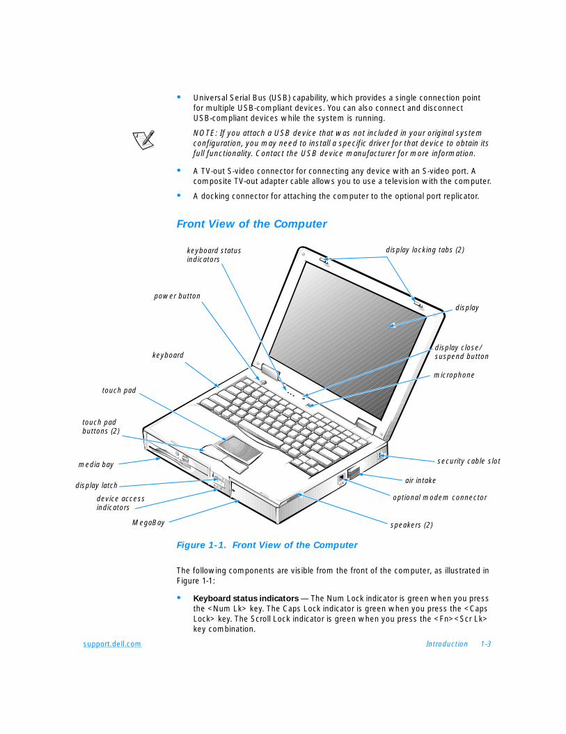
Front View of the Computer
Figure 1-1. Front View of the Computer
The following components are visible from the front of the computer, as illustrated in Figure 1-1:
• Keyboard status indicators — The Num Lock indicator is green when you press the <Num Lk> key. The Caps Lock indicator is green when you press the <Caps Lock> key. The Scroll Lock indicator is green when you press the <Fn><Scr Lk> key combination.
display
speakers (2)
touch pad buttons (2)
keyboard status indicators
display locking tabs (2)
keyboard
touch pad
power button
media bay
MegaBay
display close/suspend button
microphone
display latchair intake
security cable slot
optional modem connector device access indicators
1-4 Dell Inspiron 7500 System Reference and Troubleshooting Guide
• Display close/suspend button — When you close the display, this button activates standby mode. Do not press this button with your finger.
• Microphone — Allows you to record from a distance of 1 meter (m) (3.3 ft) in a normal tone of voice.
• Power button — Under normal circumstances, you should use the power button only to turn on the computer or to resume operation from save-to-disk suspend mode. To shut down the computer, click the Start button in the Microsoft® Windows® operating system, and then click Shut Down.
NOTE: If your operating system is "locked up"—that is, it does not respond to commands—press and hold down the power button for at least five seconds.
• Keyboard — The keyboard includes an embedded numeric keypad and two special keys that support Windows 98 Second Edition.
• Touch pad and buttons — The PS/2-compatible touch pad gives the computer full mouse functionality. Use the touch pad buttons in the same way that you would use mouse buttons.
• Media bay — The standard configuration of your computer includes a CD-ROM drive/diskette drive combination module. You can also use a DVD-ROM drive/diskette drive combination module, a DVD-ROM drive/LS-120 drive combination module, a second battery, or a third hard-disk drive in the media bay. You remove and install all devices in the same way.
NOTE: Because the Microsoft Windows NT® operating system does not support DVD technology, the DVD-ROM/diskette drive combination module and the DVD-ROM drive/LS-120 drive combination module are available only on computers running Windows 98 Second Edition.
• MegaBay — The computer is shipped with a partially charged battery in the MegaBay.
NOTE: Dell recommends connecting an AC adapter to the computer and fully charging the battery as soon as possible after unpacking the computer.
You can also use a Zip drive or a second hard-disk drive in the MegaBay.
• Display — The computer has an active-matrix XGA or SXGA color display.
• Speakers — You can enable or disable the integrated stereo speakers or external speakers by pressing <Fn> <End>. You can increase speaker volume by pressing <Fn><Page Up> and decrease speaker volume by pressing <Fn><Page Down>.
NOTES: Certain audio utilities installed on your computer also allow you to control speaker volume.
If no sound comes from the speakers, press <Fn><End> and make sure the volume control is not set to Mute by clicking the volume icon in the Microsoft Windows desktop taskbar. Also check the volume control wheel to make sure it is not turned down.
• Air intake — The air intake works with the fan as part of the computer's automatic thermal management system. When operating conditions make it necessary, a small internal fan turns on and helps draw air through the air intake.
support.dell.com Introduction 1-5
NOTICE: Do not push objects into the air intake. Keep the opening free from dust and other foreign particles. When using the computer, do not block the air intake.
NOTE: The fan spins at a very high rotational speed and makes a whirring sound. This phenomenon is normal and does not indicate a problem with the computer.
• Security cable slot — To prevent unauthorized removal of the computer, use a security cable to attach the computer to an immovable object.
Back View of the Computer
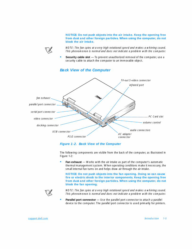
Figure 1-2. Back View of the Computer
The following components are visible from the back of the computer, as illustrated in Figure 1-2:
• Fan exhaust — Works with the air intake as part of the computer's automatic thermal management system. When operating conditions make it necessary, the small internal fan turns on and helps draw air through the air intake.
NOTICE: Do not push objects into the fan opening. Doing so can cause fire or electric shock to the interior components. Keep the opening free from dust and other foreign particles. When using the computer, do not block the fan opening.
NOTE: The fan spins at a very high rotational speed and makes a whirring sound. This phenomenon is normal and does not indicate a problem with the computer.
• Parallel port connector — Use the parallel port connector to attach a parallel device to the computer. The parallel port connector is used primarily for printers.
volume control
serial port connector
video connector
infrared port
docking connector
audio connectors USB connector
parallel port connector
PS/2 connectorAC adapter connector
PC Card slot
fan exhaust
TV-out S-video connector
1-6 Dell Inspiron 7500 System Reference and Troubleshooting Guide
• Serial port connector — Use the serial port connector to attach a serial device to the computer.
• Video connector — Use the video connector to attach an external monitor to the computer.
• TV-out S-Video connector — This connector allows you to connect your computer to a television. If your television has an S-video cable, you can plug it directly into the computer. If your television has a composite cable, use the cable that came with your computer to convert from S-video to composite video.
NOTE: Refer to the user manual that came with your television for instructions on connecting a composite cable or an S-video device.
• Docking connector — Use this connector to attach the computer to the optional port replicator.
• USB connector — Use the USB connector to attach a USB device, such as a mouse, a digital camera, or speakers to the computer. USB is a peripheral bus standard that enables automatic detection of USB-compliant peripheral devices.
• PS/2 connector — Use this connector to attach PS/2-compatible devices such as a mouse, keyboard, or external numeric keypad.
NOTES: If the computer is in standby or save-to-disk suspend mode when you attach a mouse, you can use the mouse when the computer resumes normal operation.
While the mouse is attached to the computer, the touch pad is still enabled.
• Infrared port — The infrared port lets you transfer files from the computer to another infrared device without using cable connections.
• Modem connector (optional) — If you ordered the optional internal modem, use this connector to plug in the telephone connector. This option may not be avail-able in all regions.
• PC Card slot — The PC Card slot has two connectors that support Type I, Type II, and Type III PC Cards.
• Audio connectors — Connect headphones or speakers to the line-out connector (the connector closest to the volume control wheel). Connect a microphone to the microphone-in connector in the middle. Connect record/playback devices such as cassette players and CD players to the line-in connector (the connector closest to the AC adapter connector).
• AC adapter connector — Use this connector to attach an AC adapter to the computer.

support.dell.com Introduction 1-7
Software FeaturesIn addition to the operating system, the following software is included with your computer:
• The Microsoft Windows 98 Second Edition operating system, or the Microsoft Windows NT operating system.
• A Setup program that lets you customize the operation of your computer. For more information, see Appendix B, “Using the Setup Program.”
• Drivers that tell your computer how to communicate with various types of hardware devices, such as CD-ROM drives or speakers. If you need to reinstall these drivers, or if you installed your own operating system, use the System Software CD that accompanied your computer. Instructions for installing the drivers are provided in Chapter 4, “Installing System Software”.
NOTE: The drivers on the System Software CD are the ones Dell installed on your hard-disk drive before shipping the computer to you. To download the latest version of these drivers from the following Dell Web site, http://www.dell.com/
support, click File Library, and then select your computer model.
• Optional software DVD decoder driver on systems that use the Microsoft Windows 98 Second Edition operating system. (Windows NT does not support the DVD decoder driver.)
• The Dell Diagnostics for evaluating your computer’s components and devices. This program is on the Dell Diagnostics Diskette that accompanied your computer. For information on using this program, see “Running the Dell Diagnostics” in Chapter 3.
• McAfee VirusScan virus-scanning software with systems that use Windows 98 Second Edition.
Available Options and UpgradesDell offers the following upgrade options:
• Internal 56-KB/second digital simultaneous voice and data (DSVD) telephony modem
• DVD-ROM drive and diskette drive combination module
• DVD-ROM drive and LS-120 drive combination module
• Zip drive module for the MegaBay
• External devices, such as pointing devices, printers, external monitors, external keyboards, and numeric keypads, that connect to ports on the back of the computer
• AC adapter
• Extra batteries
• Hard-disk drives
1-8 Dell Inspiron 7500 System Reference and Troubleshooting Guide
• Advanced port replicator with a network interface controller (NIC)
• Memory modules (32-, 64-, 128-, 192-, and 256-MB capacities)
• Leather and nylon carrying cases
• Microphone, external speakers, headphones
• Network PC Cards
To order any of these upgrades, call Dell. For instructions, refer to Chapter 5, “Getting Help,” or to the “Contacting Dell” section of the system Help.
Instructions for connecting or installing these options are included in Chapter 2, “Options and Upgrades.”
Getting HelpIf at any time you do not understand a procedure described in this guide, or if your computer does not perform as expected, Dell provides a number of tools to help you. For more information, see Chapter 5, “Getting Help.”
support.dell.com Options and Upgrades 2-1
C H A P T E R 2Options and Upgrades
This chapter describes the installation procedures for the options and upgrades available from Dell for your computer.
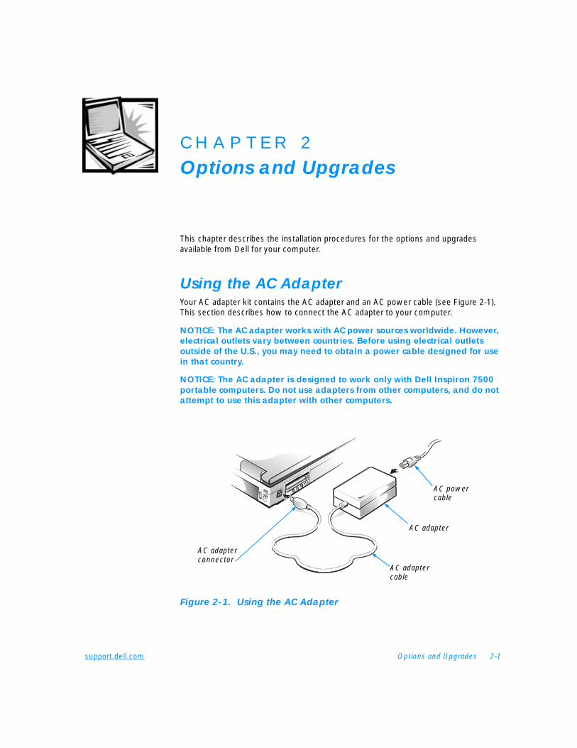
Using the AC AdapterYour AC adapter kit contains the AC adapter and an AC power cable (see Figure 2-1). This section describes how to connect the AC adapter to your computer.
NOTICE: The AC adapter works with AC power sources worldwide. However, electrical outlets vary between countries. Before using electrical outlets outside of the U.S., you may need to obtain a power cable designed for use in that country.
NOTICE: The AC adapter is designed to work only with Dell Inspiron 7500 portable computers. Do not use adapters from other computers, and do not attempt to use this adapter with other computers.
Figure 2-1. Using the AC Adapter
AC power cable
AC adapter
AC adapter cable
AC adapterconnector
2-2 Dell Inspiron 7500 System Reference and Troubleshooting Guide
To connect the AC adapter (with your computer turned either on or off), perform the following steps and refer to Figure 2-1:
1. Connect the AC power cable to the AC adapter.
2. Plug the AC adapter cable into the AC adapter connector on the computer.
3. Plug the AC power cable into an electrical outlet.
If the connection is good, the light-emitting diode (LED) on the AC adapter turns on and remains green. If the LED does not turn on, check all connections and try a different outlet. If it still does not turn on, call Dell. (See Chapter 5, “Getting Help,” for information on obtaining assistance.)
NOTE: If you are running your computer on AC power with a battery installed, the AC adapter charges the battery (if needed) and then maintains its charge.
Using the Media BayThe media bay, located on the left side of the front of the computer, supports the following devices:
• CD-ROM/diskette drive combination module
• DVD-ROM/diskette drive combination module
• DVD-ROM/LS-120 drive combination module
NOTE: Because the Microsoft Windows NT operating system does not support DVD technology, the DVD-ROM/diskette drive module and the DVD-ROM/LS-120 drive module are available only on computers that use the Microsoft Windows 98 Second Edition operating system. If you choose to install Windows NT on a system that originally came with a DVD-ROM/diskette drive module, the DVD-ROM drive will function as a CD-ROM drive.
• Second battery
• Third hard-disk drive (when a second hard-disk drive is installed in the MegaBay, as described in “Using the MegaBay,” found later in this chapter)
When you receive your computer, a CD-ROM/diskette drive combination module is installed in the media bay.
NOTICE: Do not change devices while the computer is connected to a port replicator. The docking connector can be irreparably damaged.
To change a device in the media bay, perform the following steps:
1. Save and close any open files, exit any open application programs, and shut down the computer.
2. Remove the currently installed device:
a. Close the display and turn the computer over so that it is oriented as illustrated in Figure 2-2.
support.dell.com Options and Upgrades 2-3
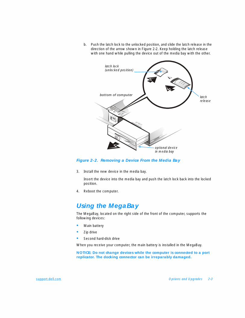
b. Push the latch lock to the unlocked position, and slide the latch release in the direction of the arrow shown in Figure 2-2. Keep holding the latch release with one hand while pulling the device out of the media bay with the other.
Figure 2-2. Removing a Device From the Media Bay
3. Install the new device in the media bay.
Insert the device into the media bay and push the latch lock back into the locked position.
4. Reboot the computer.
Using the MegaBayThe MegaBay, located on the right side of the front of the computer, supports the following devices:
• Main battery
• Zip drive
• Second hard-disk drive
When you receive your computer, the main battery is installed in the MegaBay.
NOTICE: Do not change devices while the computer is connected to a port replicator. The docking connector can be irreparably damaged.
bottom of computer
optional device in media bay
latch lock (unlocked position)
latch release
2-4 Dell Inspiron 7500 System Reference and Troubleshooting Guide
To change a device in the MegaBay, perform the following steps:
1. Save and close any open files, and exit any open application programs.
2. Turn off the computer.
3. Remove the currently installed device from the MegaBay:
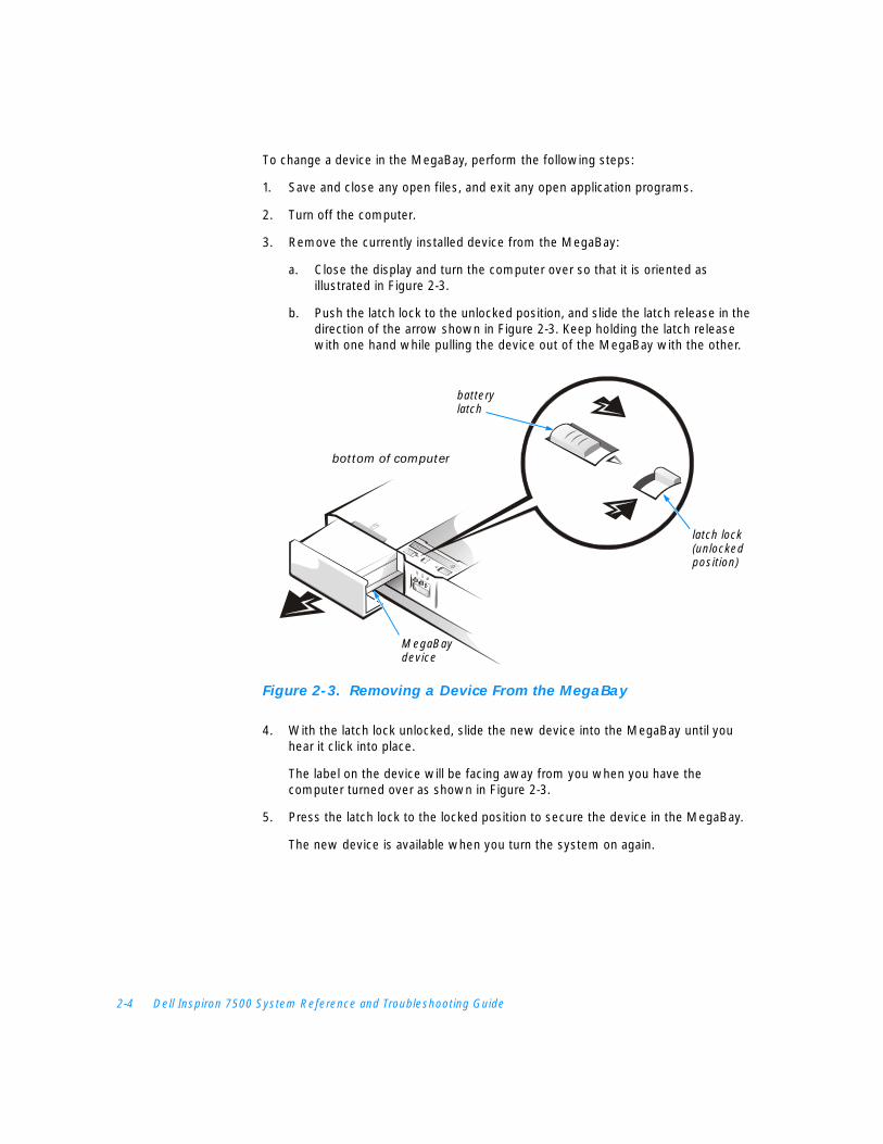
a. Close the display and turn the computer over so that it is oriented as illustrated in Figure 2-3.
b. Push the latch lock to the unlocked position, and slide the latch release in the direction of the arrow shown in Figure 2-3. Keep holding the latch release with one hand while pulling the device out of the MegaBay with the other.
Figure 2-3. Removing a Device From the MegaBay
4. With the latch lock unlocked, slide the new device into the MegaBay until you hear it click into place.
The label on the device will be facing away from you when you have the computer turned over as shown in Figure 2-3.
5. Press the latch lock to the locked position to secure the device in the MegaBay.
The new device is available when you turn the system on again.
battery latch
MegaBay device
latch lock (unlocked position)
bottom of computer
support.dell.com Options and Upgrades 2-5
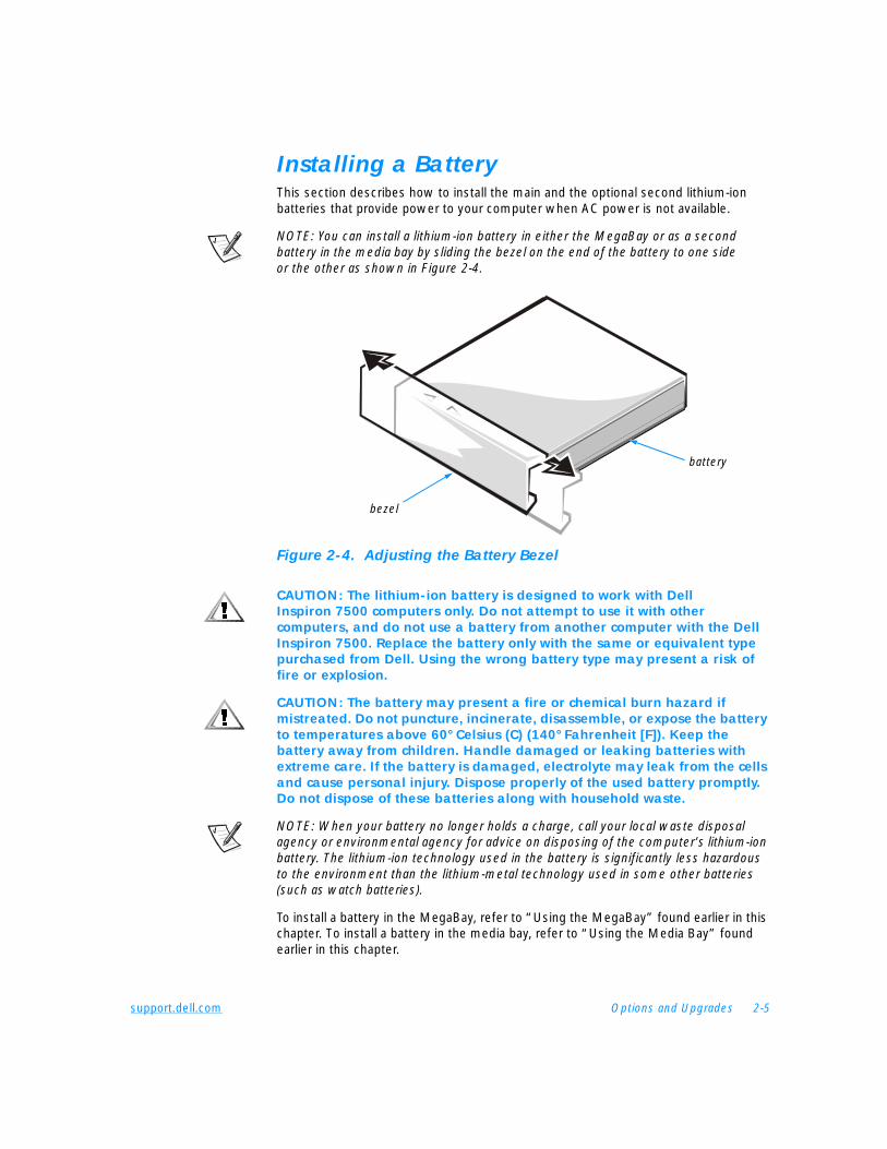
Installing a BatteryThis section describes how to install the main and the optional second lithium-ion batteries that provide power to your computer when AC power is not available.
NOTE: You can install a lithium-ion battery in either the MegaBay or as a second battery in the media bay by sliding the bezel on the end of the battery to one side or the other as shown in Figure 2-4.
Figure 2-4. Adjusting the Battery Bezel
CAUTION: The lithium-ion battery is designed to work with Dell Inspiron 7500 computers only. Do not attempt to use it with other computers, and do not use a battery from another computer with the Dell Inspiron 7500. Replace the battery only with the same or equivalent type purchased from Dell. Using the wrong battery type may present a risk of fire or explosion.
CAUTION: The battery may present a fire or chemical burn hazard if mistreated. Do not puncture, incinerate, disassemble, or expose the battery to temperatures above 60° Celsius (C) (140° Fahrenheit [F]). Keep the battery away from children. Handle damaged or leaking batteries with extreme care. If the battery is damaged, electrolyte may leak from the cells and cause personal injury. Dispose properly of the used battery promptly. Do not dispose of these batteries along with household waste.
NOTE: When your battery no longer holds a charge, call your local waste disposal agency or environmental agency for advice on disposing of the computer’s lithium-ion battery. The lithium-ion technology used in the battery is significantly less hazardous to the environment than the lithium-metal technology used in some other batteries (such as watch batteries).
To install a battery in the MegaBay, refer to “Using the MegaBay” found earlier in this chapter. To install a battery in the media bay, refer to “Using the Media Bay” found earlier in this chapter.
bezel
battery
2-6 Dell Inspiron 7500 System Reference and Troubleshooting Guide
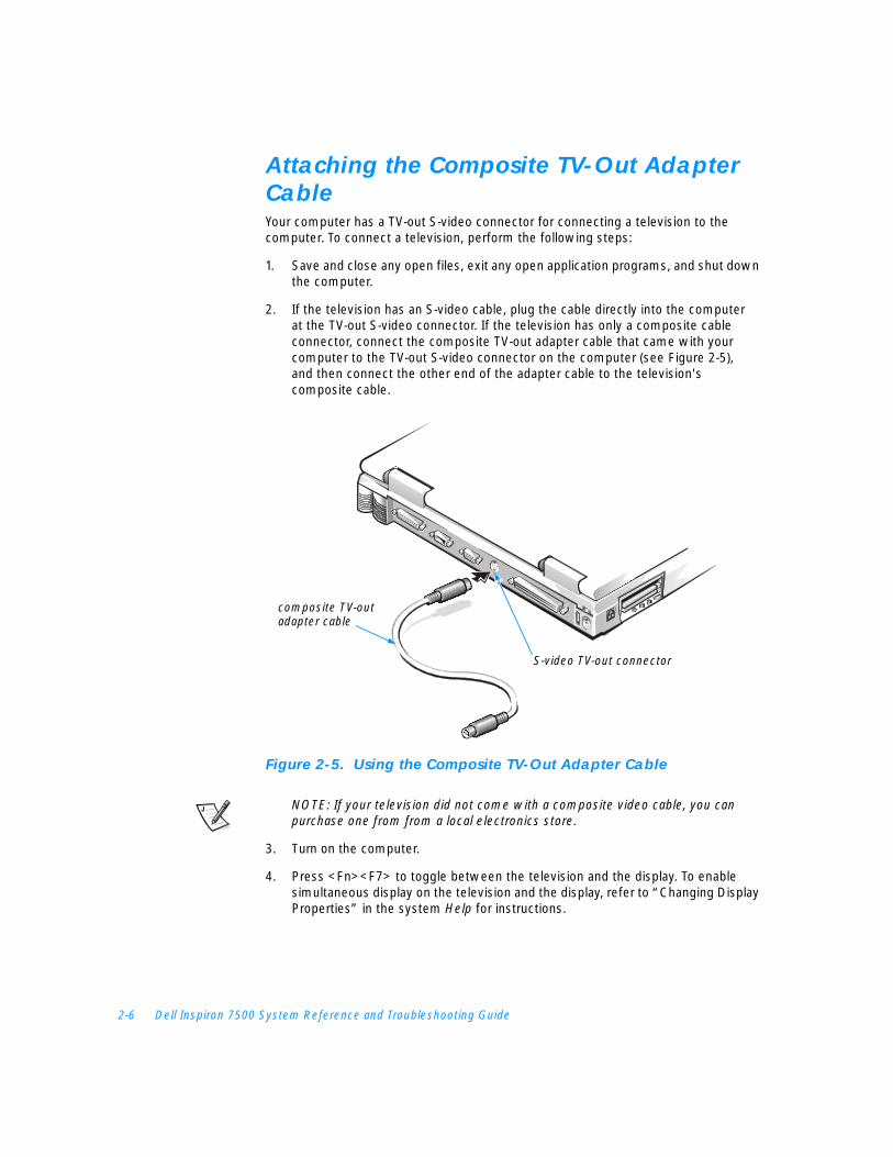
Attaching the Composite TV-Out Adapter CableYour computer has a TV-out S-video connector for connecting a television to the computer. To connect a television, perform the following steps:
1. Save and close any open files, exit any open application programs, and shut down the computer.
2. If the television has an S-video cable, plug the cable directly into the computer at the TV-out S-video connector. If the television has only a composite cable connector, connect the composite TV-out adapter cable that came with your computer to the TV-out S-video connector on the computer (see Figure 2-5), and then connect the other end of the adapter cable to the television's composite cable.
Figure 2-5. Using the Composite TV-Out Adapter Cable
NOTE: If your television did not come with a composite video cable, you can purchase one from from a local electronics store.
3. Turn on the computer.
4. Press <Fn><F7> to toggle between the television and the display. To enable simultaneous display on the television and the display, refer to “Changing Display Properties” in the system Help for instructions.
S-video TV-out connector
composite TV-out adapter cable
support.dell.com Options and Upgrades 2-7
NOTE: If you are outside the U.S., you may need to change the Television Type setting in the Setup program. See Appendix B, “Using the Setup Program,” for more information.
Installing an Internal Hard-Disk DriveNOTE: If you ordered a second and/or third hard-disk drive from Dell, refer to the documentation that accompanied the drive(s) for instructions on installing it in the MegaBay or the media bay.
NOTICE: Hard-disk drives are extremely fragile and must be handled carefully. Even a slight jar or bump can damage the spinning heads and plates, thus rendering the drive inoperable.
CAUTION: The hard-disk drive may be hot to the touch. Do not touch the metal housing of the hard-disk drive if you remove the drive from the computer when the drive is hot.
NOTES: You will need the Microsoft Windows Installation CD and the System Software CD to install software on the new hard-disk drive.
The computer’s basic input/output system (BIOS) may not support hard-disk drives obtained from vendors other than Dell. Dell does not guarantee compatibility or provide support for hard-disk drives obtained from other sources.
NOTICE: To prevent data loss, shut down your computer before removing or installing your hard-disk drive. Do not remove the hard-disk drive if the computer is in standby mode or save-to-disk suspend mode, or if the hard-disk drive access indicator is lit.
To install an internal hard-disk drive, perform the following steps:
1. Save and close any open files, exit any open application programs, and shut down the computer.
2. Remove any installed batteries from the MegaBay and/or media bay.
For instructions, refer to “Using the Media Bay” and/or “Using the MegaBay” found earlier in this chapter.
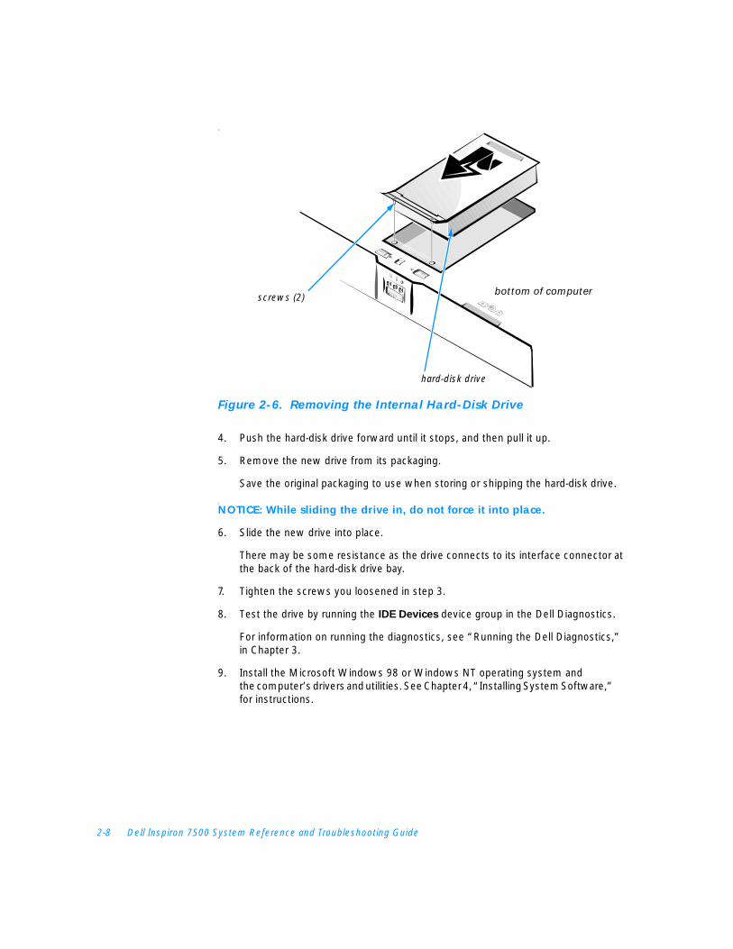
3. Turn the computer over, and loosen the two screws securing the hard-disk drive cover as shown in Figure 2-6.
The screws are held captive in the lip of the carrier. A spring causes the front edge of the cover to pop up. If the front edge of the cover does not pop up, pull on one of the screws to lift the front edge.
NOTICE: When the hard-disk drive is not in the computer, protect the drive from exposure to static electricity by storing it in protective packaging.
2-8 Dell Inspiron 7500 System Reference and Troubleshooting Guide
C
Figure 2-6. Removing the Internal Hard-Disk Drive
4. Push the hard-disk drive forward until it stops, and then pull it up.
5. Remove the new drive from its packaging.
Save the original packaging to use when storing or shipping the hard-disk drive.
C
NOTICE: While sliding the drive in, do not force it into place.
6. Slide the new drive into place.
There may be some resistance as the drive connects to its interface connector at the back of the hard-disk drive bay.
7. Tighten the screws you loosened in step 3.
8. Test the drive by running the IDE Devices device group in the Dell Diagnostics.
For information on running the diagnostics, see “Running the Dell Diagnostics,” in Chapter 3.
9. Install the Microsoft Windows 98 or Windows NT operating system and the computer’s drivers and utilities. See Chapter 4, “Installing System Software,” for instructions.
hard-disk drive
bottom of computerscrews (2)

support.dell.com Options and Upgrades 2-9
Returning a Hard-Disk Drive to DellIf you need to return your hard-disk drive, you must ship it to Dell in its original foam packaging (see Figure 2-7). Otherwise, the hard-disk drive may be damaged while in transit.
Figure 2-7. Repackaging the Hard-Disk Drive
Installing Memory ModulesMemory modules for your computer are available in 32-, 64-, 128-, 192-, and256-megabyte (MB) sizes.
NOTE: Your computer has two memory module sockets (slot 1 and slot 2). You can install all sizes of memory modules you purchase from Dell (but which Dell does not install), except the 192-MB memory module, in either socket. If you purchase a non-Dell-installed 192-MB memory module, you must install it in slot 2.
To install memory module(s), perform the following steps.
CAUTION: Before working inside your computer, read “Protecting Against Electrostatic Discharge” in the “Safety Instructions” of this guide.
NOTICE: Do not install or remove a memory module when the computer is turned on or in save-to-disk suspend mode.
1. Save and close any open files, exit any open application programs, and shut down the computer.
2. Unplug the computer and any attached peripherals from the electrical outlets.
hard-disk drive

2-10 Dell Inspiron 7500 System Reference and Troubleshooting Guide
3. Remove any installed batteries from the MegaBay and/or media bay. For instructions, refer to “Using the MegaBay” and/or “Using the Media Bay” found earlier in this chapter.
4. Ground yourself by touching a metal input/output (I/O) connector on the back of the computer.
5. Turn the computer over, and remove the memory module cover as shown in Figure 2-8.
Slide the memory module cover as far as it will go in the direction of the arrow, and then lift it away from the computer.
Figure 2-8. Removing the Memory Module Cover
NOTICE: To prevent damage to the computer, do not use tools to spread the inner metal tabs of the socket when you are installing or removing a memory module.
6. If you are replacing one or more memory modules, remove the memory module(s) as shown in Figure 2-9.
NOTE: If one memory module is already installed and you are adding a second memory module, put the second module in the available slot. Removing existing module(s) is necessary only if they are being replaced. Depending on how you ordered your computer, one or two modules may already be installed.
Using your fingernails, carefully spread apart the inner metal tabs of the memory module socket just far enough for the memory module to disengage from the socket (the module should pop up slightly). Then lift the memory module away from the socket.
bottom of computer
memory module cover

support.dell.com Options and Upgrades 2-11
Figure 2-9. Removing a Memory Module
7. Install the new memory module(s) as shown in Figure 2-10:
a. Align the notch in the edge connector with the slot in the center of the memory module socket.
b. Press the memory module’s edge connector firmly into the socket.
c. Pivot the module down until it clicks.
Figure 2-10. Installing a Memory Module
8. Replace the memory module cover.
9. Reinstall any batteries you removed in step 3.
10. Reconnect your computer and peripherals to electrical outlets.
11. Turn on the peripherals and then turn on the computer.
As the computer boots, it detects the additional memory and automatically updates the system configuration information.
bottom of computer
memory module
slot 2
slot 1
bottom of computer
memory module
slot 2
slot 1
2-12 Dell Inspiron 7500 System Reference and Troubleshooting Guide
12. Confirm that the system configuration information reflects the newly installed memory by checking the System Memory option on the Main menu of theSetup program.
To enter the Setup program, press <F2> while the computer is booting. The Main menu appears. If the System Memory total is incorrect, the memory modules may not be installed properly. Repeat steps 1 through 11 until the memory total is correct.
NOTE: The computer will not boot if without a memory module installed, nor if the installed module(s) are not seated properly in the socket(s). No error message or beep code indicates this failure.
13. Run the System Memory device group in the Dell Diagnostics to confirm that the installed memory modules are operating correctly.
For instructions, see “Running the Dell Diagnostics” in Chapter 3.
14. If you have added additional memory to your computer, you will need to delete and recreate the save-to-disk suspend file on your hard-disk drive so that it is large enough to accommodate the new memory.
For instructions, refer to the next subsection, “Creating the Save-to-Disk Suspend File.”
Creating the Save-to-Disk Suspend FileThe save-to-disk suspend file on your hard-disk drive cannot be accessed by the operating system or application programs. When the save-to-disk suspend mode is activated, all system data is stored in this file.
To create a save-to-disk suspend file if you installed a new hard-disk drive, if you removed the file, or if you are rebuilding a corrupted hard-disk drive, perform the following steps.
NOTE: If you installed memory to increase system memory, delete the save-to-disk suspend file and then complete the following procedure. To delete the save-to-disk suspend file, type phdisk /delete /file at an MS-DOS® prompt and press <Enter>.
1. Save and close any open files, exit any open application programs, and shut down the computer.
2. Insert the Microsoft Boot Disk Windows 98 Series diskette into the diskette drive.
3. When the Microsoft Windows 98 Startup Menu appears, press the down-arrow key to select Start computer with CD-ROM support and press <Enter>.
4. When A:\> appears on the screen, insert the System Software CD into your CD-ROM or DVD-ROM drive.
support.dell.com Options and Upgrades 2-13
5. At the MS-DOS prompt, type x:/, where x is the drive letter of your CD-ROM or DVD-ROM drive. Drive letter D is typical for CD-ROM or DVD-ROM drives.
6. Type cd\utility and press <Enter>.
7. Type phdisk /create /file and press <Enter>.
NOTE: Make sure to place a space between phdisk /create and /file.
The utility calculates the size of the file, in kilobytes, based on the amount of system memory in your computer, plus 4 or 8 MB to handle video memory, plus 2 MB to handle additional system requirements.
8. Follow the instructions on your screen to create the save-to-disk suspend file.
To check the size of the save-to-disk suspend file, type phdisk /info at an MS-DOS prompt and press <Enter>.
If you need to delete the save-to-disk suspend file, type phdisk /delete /file at an MS-DOS prompt and press <Enter>.
Port ReplicatorIf you purchased a port replicator from Dell, see the documentation that came with the port replicator for instructions on its use.
Connecting Other External DevicesYou can connect the following external devices to your Dell computer:
• Speakers (and other audio devices)
• Personal System/2 (PS/2) or universal serial bus (USB) Keyboard
• PS/2 or USB mouse
• Keypad
• Monitor
• Serial devices
• Parallel devices
• Infrared devices
For instructions, refer to the section titled “Connecting External Devices” in the system Help. To open the Help, click the Start button, point to Programs—> Dell Documents, and click Dell Inspiron 7500 System Help.

2-14 Dell Inspiron 7500 System Reference and Troubleshooting Guide

support.dell.com Basic Troubleshooting 3-1
C H A P T E R 3Basic Troubleshooting
This chapter guides you through some initial checks and procedures that can solve basic computer problems. It also provides detailed troubleshooting information and procedures to solve more complex problems. Complete the checks in this chapter before you call Dell for technical assistance; even if these checks do not provide an immediate solution, they can help technicians help you diagnose and fix the problem.
NOTES: When you see the question “Is the problem resolved?” in a troubleshooting procedure, repeat the operation that caused the problem to see if it still occurs.
Before you begin any of the troubleshooting procedures, make sure the Quiet Boot option is set to Disabled in the Main menu of the Setup program. See Appendix B, “Using the Setup Program,” for information on using the Setup program.
CAUTION: The only time you should ever access the inside of your computer is when you are installing memory modules.
CAUTION: To help prevent possible damage to the system board, wait 5 seconds after turning off the computer before you disconnect a peripheral device or remove a memory module.
Checking the BasicsTo perform an initial check of your computer, perform the following steps.
NOTE: If your computer is wet or damaged, refer to “Troubleshooting a Wet Computer” or “Troubleshooting a Damaged Computer” found later in this chapter.
1. If the problem you are experiencing began after making a change to your computer, such as installing new hardware or software, undo the change if possible.
If the problem is resolved, check any documentation that came with the option you attempted to install or that describes the change you made. In particular, read any text files (such as readme.txt) included with the software package or hardware product; such files contain information that updates or supplements the documentation for the software or hardware. Typically, readme files provide installation information, describe new product enhancements or corrections that have not yet been documented, and list known problems.

3-2 Dell Inspiron 7500 System Reference and Troubleshooting Guide
If you were trying to install new hardware, double-check configuration settings and available system resources. Refer to the documentation that accompanied the hardware device for more information. Also make sure you changed the appropriate settings in the Setup program for the system’s new hardware configuration (refer to Appendix B, “Using the Setup Program”).
If you need technical assistance, contact the product manufacturer or the company from whom you purchased the product.
NOTE: DellWareSM products are supported by the item's manufacturer. To receive product support information, refer to the manufacturer’s documentation that accompanied the item.
2. Perform the steps described in the next subsection, “Checking Connections.”
3. Check the items listed in “Environmental Factors” found later in this chapter.
4. For power problems, refer to “Power” found later in this chapter.
5. Check the boot routine indications in Table 3-1.
NOTE: The boot routine is the operating system’s attempt to load its files into memory from the boot-up sector on the hard-disk drive or bootable diskette.
6. If you hear a beep code or see a system message, refer to Appendix C, “System Messages and Beep Codes.”
7. If appropriate, refer to the subsections titled “Monitor,” “Speakers,” “Modem,” and “Drives” found later in this chapter.
8. Verify that the settings in the Setup program match your computer’s configura-tion as explained in Appendix B, “Using the Setup Program.”
9. Use the Dell Diagnostics to check your computer (refer to “Running the Dell Diagnostics” found later in this chapter).
10. If the problem persists, refer to Chapter 5, “Getting Help,” for instructions on obtaining technical assistance.
Checking Connections Loose or improperly connected cables are likely sources of problems for your computer, external monitor, or other peripherals (such as a printer, external keyboard, or mouse). A quick check of all cable connections can easily solve these problems. If the connector has two small screws, make sure the screws are tight. In addition, check for damaged or frayed cables and for bent pins on connectors.
NOTE: See the “System Features” section of the system Help for the location of your computer’s external connectors and controls.
Be sure the following items are properly connected or installed:
• AC adapter and AC power cable
• Main battery or any other optional device installed in the MegaBay
support.dell.com Basic Troubleshooting 3-3
• Second battery or any other optional device installed in the media bay
• Cables that connect external devices through the input/output (I/O) connectors and ports on the computer.
Environmental FactorsA number of external factors, including temperature extremes and humidity, magnetic influences, sources of electromagnetic interference (EMI), and poor input power or signal quality, can interfere with the performance of your computer and attached devices. Monitors are especially susceptible to these environmental factors. The following items can adversely affect the performance of a computer:
• Inadequate ventilation from operating the computer in a confined space, such as a desk enclosure
• Direct sunlight causing the computer to overheat
• Line noise or power drops and surges from electrical outlets due to poor wiring
• Line noises or surges through telephone lines
• High-voltage electrical appliances on the same circuit or operating in close proximity to the computer
• Speakers, especially subwoofer, or telephone too close to the monitor, generating magnetic fields that distort the display image
• Fluorescent lights causing display flickering or distortion
• Electrical extension cords and keyboard and mouse extension cables
• Too many devices on a power strip or multiple power strips from one electrical outlet
• Electrical conduits in an adjoining wall or elevators on the other side of the wall
• Large metal beams inside the wall behind the computer
If removing potential sources of problems does not help, try moving the computer.
PowerIf you are experiencing problems with power to your computer, perform the following tasks:
• Check the computer’s power indicator. When lit, the power indicator verifies that the power supply is operating.
• If your computer is connected to a power strip, turn the power strip off and then on again.
• Plug the computer directly into an electrical outlet, bypassing any power protection devices.
• Plug a device, such as a lamp that you know works, into the electrical outlet to make sure the power source is okay.
3-4 Dell Inspiron 7500 System Reference and Troubleshooting Guide
ModemNOTICE: Connect the modem to an analog line only. Using a nonanalog line, such as a digital or private branch exchange (PBX) line, will damage the modem.
NOTE: If your modem can dial and connect to one Internet service provider (ISP) or to a fax machine, your modem is functioning properly. For assistance, contact the ISP to which you cannot connect.
If you are experiencing problems with a modem, perform the following checks:
• If you have any other telephone devices plugged into this line, such as answering machines, dedicated fax machines, or line splitters, then bypass them and plug the modem cable directly into the telephone connector on the wall.
• Reseat the cable connections.
• Try a different cable; if you are using a cable that is 10 feet or more in length, try a shorter one.
• Disconnect the cable from the modem and plug it directly into a telephone. Listen for a dial tone.
• Low connection speeds can be caused by line noise. If you have persistent problems, try connecting the modem to a different telephone connector or contact your telephone company to check for data noise and imbalanced lines.
DrivesIf you have diskette drive problems, perform the following checks:
• Make sure the diskette is not write-protected if you are trying to copy data to it.
• Try a different diskette in the drive. If the new diskette works, the original one may be defective.
• Check drive operations at the MS-DOS® prompt in the Dell Diagnostics (refer to “Running the Dell Diagnostics” found later in this chapter) and the Windows operating system.
• Check the settings on the Diskette Options submenu of the Setup program as described in Appendix B, “Using the Setup Program.”
• Run the Diskette device group as described in “Running the Dell Diagnostics” found later in this chapter.
If you have CD-ROM or DVD-ROM drive problems, perform the following checks.
NOTE: Inconsistencies in the manufacturing of CD-ROM media may cause some higher-speed CD-ROM drives to vibrate more than others. Such vibration and associated noise do not indicate a defect in the drive or the CD.
• Double-click My Computer and check to see if the drive is recognized by the computer. Most of the common boot sector viruses cause the CD-ROM or DVD-ROM drive to “disappear.” Use virus-scanning software (if Dell installed

support.dell.com Basic Troubleshooting 3-5
Windows 98 on your computer, you should already have virus-scanning software) to check for and remove any viruses.
• Clean the disc with a soft, lint-free cloth and isopropyl alcohol.
• Clean the drive as described in the next subsection, “Cleaning Diskette Drives.”
• Try another CD or DVD title.
NOTE: Because of different conventions currently used in the industry, not all DVD titles work in all DVD-ROM drives.
• Enter the Setup program as described in Appendix B, “Using the Setup Program,” and verify that IDE Controller is set to Both.
• Run the IDE Devices device group as described in “Running the Dell Diagnostics” found later in this chapter.
• Refer to “Troubleshooting the CD-ROM or DVD-ROM Drive” found later in this chapter for further troubleshooting information.
If you have hard-disk drive problems, perform the following checks:
• For Windows 98, run the ScanDisk utility by clicking the Start button, pointing to Programs—> Accessories—> System Tools, and clicking ScanDisk.
• For Windows NT, run the error-checking utility by opening the property sheet of the affected volume(s) and clicking Check Now in the Error-checking section of the Tools tab.
• Run the IDE (ATA/ATAPI) Devices device group as described in “Running the Dell Diagnostics” found later in this chapter.
• Check the settings on the IDE Configuration submenu of the Setup program as described in Appendix B, “Using the Setup Program.”
Cleaning Diskette DrivesYou can clean a diskette drive using a commercially available cleaning kit. These kits contain pretreated diskettes to nonabrasively remove contaminants that accumulate during normal operation.
If the kit does not contain instructions, insert a pretreated diskette into the drive and turn on the system. After 20 or 30 seconds, remove the diskette from the drive.
NOTICE: Do not attempt to clean drive heads with a swab. You may accidentally misalign the heads, rendering the drive inoperable.
Look and Listen Looking at and listening to your computer is important in determining the source of a problem. Look and listen for the indications described in Table 3-1.
If the problem is still not resolved, see the next subsection, “Setup Options.”
3-6 Dell Inspiron 7500 System Reference and Troubleshooting Guide
NOTE: Before you begin any of the troubleshooting procedures, make sure the Quiet Boot option is set to Disabled in the Main menu of the Setup program. See Appendix B, “Using the Setup Program,” for information on using the Setup program.
Setup OptionsYou can easily correct certain computer problems by verifying the settings for Setup program options. When you boot the computer, it compares the system configuration information with the current hardware configuration. If the computer’s hardware configuration doesn’t match the information recorded by the Setup program options, an error message may appear on the display.
Table 3-1. Boot Routine Indications
Look for: Action
An error message See Appendix C, “System Messages and Beep Codes.”
The power indicator If the computer’s power status indicator does not come on, see “Troubleshooting a Power Failure” found later in this chapter.
The keyboard status indicators
Press the <Num Lock> key, the <Caps Lock> key, and the <Scroll Lock> key to toggle their respective status indicator. If the indicators do not light up, run the PC-AT Compatible Keyboards device group in the Dell Diagnostics (for instructions, see “Running the Dell Diagnostics” found later in this chapter).
The diskette-drive access indicator
The diskette-drive access indicator lights up when data is accessed on the diskette drive. You can test this indicator by inserting a diskette into the drive, typing dir a: at an MS-DOS prompt, and pressing <Enter>. If the diskette-drive access indicator does not light up, see “Troubleshooting the Diskette Drive” found later in this chapter.
The CD-ROM/hard-disk drive access indicator
The CD-ROM/hard-disk drive access indicator lights up when data is accessed on the CD-ROM drive or the hard-disk drive. You can test this indicator by typing dir c: at an MS-DOS prompt and pressing <Enter>. If the CD-ROM/hard-disk drive access indicator does not light up, see “Troubleshooting the Hard-Disk Drive” or “Troubleshooting the CD-ROM or DVD-ROM Drive” found later in this chapter.
A series of beeps See Appendix C, “System Messages and Beep Codes.”
An unfamiliar constant scraping or grinding sound when a drive is accessed
Make sure the sound is not caused by the application program that is running. The sound could also be caused by a hardware malfunction. See Chapter 5, “Getting Help,” for instructions on obtaining technical assistance from Dell.
The absence of a familiar sound
When you turn on the computer, you can hear the hard-disk drive spin up, and the computer tries to access the boot files from the hard-disk drive or the diskette drive. If your computer does not boot, call Dell for technical assistance. (See Chapter 5, “Getting Help,” for instructions.) Otherwise, see “Running the Dell Diagnostics” found later in this chapter.
NOTE: For the full name of an abbreviation or acronym used in this table, see the Glossary in the system Help.

support.dell.com Basic Troubleshooting 3-7
To fix this problem, correct the appropriate options in the Setup program. See Appendix B, “Using the Setup Program,” for detailed information about the Setup program and its options.
If, after checking the setup options, you have not resolved the problem, see “Running the Dell Diagnostics” found later in this chapter.
Finding Software SolutionsBecause most computers have several application programs installed in addition to the operating system, isolating a software problem can be confusing. Software errors can also appear to be hardware malfunctions at first. Software problems can result from the following circumstances:
• Improper installation or configuration of a program
• Input errors
• Drivers that may conflict with certain application programs
• Memory conflicts resulting from the use of terminate-and-stay-resident (TSR) programs, such as drivers
• Interrupt conflicts between devices
You can confirm that a computer problem is caused by software by first running the System Board Devices device group as described in “Running the Dell Diagnostics” found later in this chapter. If all tests in the device group complete successfully, the error condition is most likely caused by software.
The following subsections provide general guidelines for analyzing some software problems. For detailed troubleshooting information on a particular program, see the documentation that accompanied the software or consult the support service for the software.
Installing and Configuring Software When you obtain software, check it for viruses using virus-scanning software before installing it on the computer’s hard-disk drive. Viruses can quickly use all available system memory, damage and/or destroy data stored on the hard-disk drive, and permanently affect the performance of the programs they infect. Several commercial virus-scanning programs are available for purchase, and most bulletin board services (BBSs) archive freely distributed virus-scanning programs that you can download with a modem.
Before installing a program, read its documentation to learn how the program works, what hardware it requires, and what its defaults are. A program usually includes installation instructions in its accompanying documentation and a software installation routine on its program diskettes.
The software installation routine assists you in transferring the appropriate program files to the computer’s hard-disk drive. Installation instructions may provide details about how to configure the operating system to successfully run the program. Always
3-8 Dell Inspiron 7500 System Reference and Troubleshooting Guide
read the installation instructions before running a program’s installation routine. If you are instructed to modify the start-up files, see the documentation that came with the operating system for instructions.
When you run the installation routine, be prepared to respond to prompts for information about how the computer’s operating system is configured, what type of computer you have, and what peripherals are connected to the computer.
Start-Up Files Whenever you start or reboot the computer, the operating system executes commands from its start-up files.
These files contain commands that automatically configure the operating system by setting system parameters, starting memory-resident programs, and loading device driver software. If you experience program conflicts or memory error messages, check the commands for memory-resident programs in the start-up files of the operating system. (For information on start-up files, see the documentation that came with the operating system). If a program or peripheral does not work correctly, check the product’s documentation to see if you need to modify these files.
Using Software The following subsections discuss errors that can occur while using software.
Error MessagesError messages can be produced by an application program, the operating system, or the computer. Appendix C, “System Messages and Beep Codes,” discusses the error messages generated by the computer. If you receive an error message not listed in Appendix C, check the operating system or application program documentation.
Input ErrorsIf a specific key or set of keys is pressed at the wrong time, a program may give you unexpected results. See the documentation that came with the application program to make sure the values or characters you are entering do not conflict with the application program you are using.
Make sure the operating system is compatible with the programs you use. Keep in mind that whenever you change the parameters of the computer’s operating system, you may affect the successful operation of the programs. Sometimes, after modifying the operating system, you may need to reinstall a program that no longer runs properly.
Memory-Resident Programs There are a variety of utilities and supplementary programs that can be loaded either when the computer boots or from an operating system prompt. These programs are designed to stay resident in system memory and thus always be available for use. Because they remain in the computer’s memory, memory conflicts and errors can
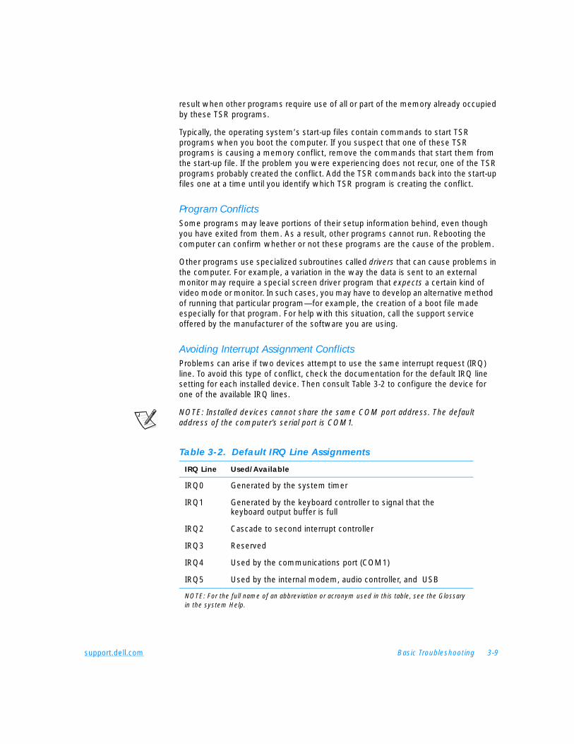
support.dell.com Basic Troubleshooting 3-9
result when other programs require use of all or part of the memory already occupied by these TSR programs.
Typically, the operating system’s start-up files contain commands to start TSR programs when you boot the computer. If you suspect that one of these TSR programs is causing a memory conflict, remove the commands that start them from the start-up file. If the problem you were experiencing does not recur, one of the TSR programs probably created the conflict. Add the TSR commands back into the start-up files one at a time until you identify which TSR program is creating the conflict.
Program ConflictsSome programs may leave portions of their setup information behind, even though you have exited from them. As a result, other programs cannot run. Rebooting the computer can confirm whether or not these programs are the cause of the problem.
Other programs use specialized subroutines called drivers that can cause problems in the computer. For example, a variation in the way the data is sent to an external monitor may require a special screen driver program that expects a certain kind of video mode or monitor. In such cases, you may have to develop an alternative method of running that particular program—for example, the creation of a boot file made especially for that program. For help with this situation, call the support service offered by the manufacturer of the software you are using.
Avoiding Interrupt Assignment Conflicts Problems can arise if two devices attempt to use the same interrupt request (IRQ) line. To avoid this type of conflict, check the documentation for the default IRQ line setting for each installed device. Then consult Table 3-2 to configure the device for one of the available IRQ lines.
NOTE: Installed devices cannot share the same COM port address. The default address of the computer’s serial port is COM1.
Table 3-2. Default IRQ Line Assignments
IRQ Line Used/Available
IRQ0 Generated by the system timer
IRQ1 Generated by the keyboard controller to signal that the keyboard output buffer is full
IRQ2 Cascade to second interrupt controller
IRQ3 Reserved
IRQ4 Used by the communications port (COM1)
IRQ5 Used by the internal modem, audio controller, and USB
NOTE: For the full name of an abbreviation or acronym used in this table, see the Glossary in the system Help.
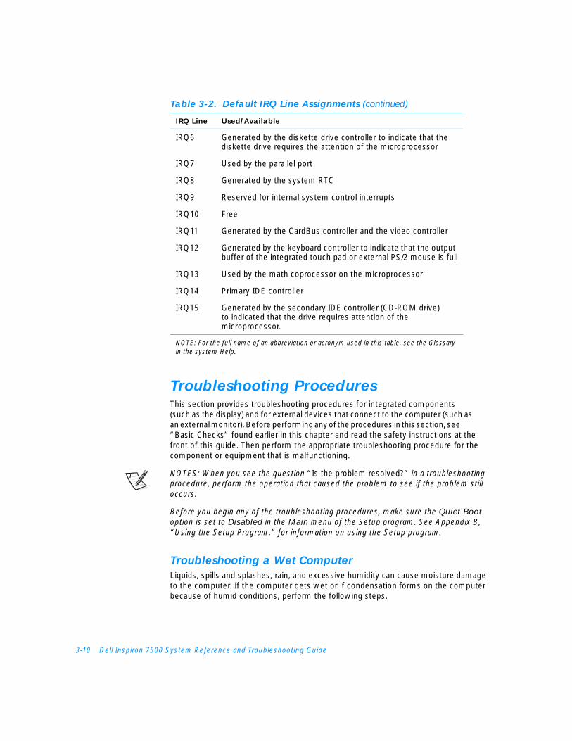
3-10 Dell Inspiron 7500 System Reference and Troubleshooting Guide
Troubleshooting ProceduresThis section provides troubleshooting procedures for integrated components (such as the display) and for external devices that connect to the computer (such as an external monitor). Before performing any of the procedures in this section, see “Basic Checks” found earlier in this chapter and read the safety instructions at the front of this guide. Then perform the appropriate troubleshooting procedure for the component or equipment that is malfunctioning.
NOTES: When you see the question “Is the problem resolved?” in a troubleshooting procedure, perform the operation that caused the problem to see if the problem still occurs.
Before you begin any of the troubleshooting procedures, make sure the Quiet Boot
option is set to Disabled in the Main menu of the Setup program. See Appendix B, “Using the Setup Program,” for information on using the Setup program.
Troubleshooting a Wet ComputerLiquids, spills and splashes, rain, and excessive humidity can cause moisture damage to the computer. If the computer gets wet or if condensation forms on the computer because of humid conditions, perform the following steps.
IRQ6 Generated by the diskette drive controller to indicate that the diskette drive requires the attention of the microprocessor
IRQ7 Used by the parallel port
IRQ8 Generated by the system RTC
IRQ9 Reserved for internal system control interrupts
IRQ10 Free
IRQ11 Generated by the CardBus controller and the video controller
IRQ12 Generated by the keyboard controller to indicate that the output buffer of the integrated touch pad or external PS/2 mouse is full
IRQ13 Used by the math coprocessor on the microprocessor
IRQ14 Primary IDE controller
IRQ15 Generated by the secondary IDE controller (CD-ROM drive) to indicated that the drive requires attention of the microprocessor.
Table 3-2. Default IRQ Line Assignments (continued)
IRQ Line Used/Available
NOTE: For the full name of an abbreviation or acronym used in this table, see the Glossary in the system Help.
support.dell.com Basic Troubleshooting 3-11
CAUTION: Perform step 1 of the following procedure only after you are certain that it is safe to do so. If the computer is connected to an electrical outlet, Dell recommends turning off AC power at the circuit breaker before attempting to remove the power cables from the electrical outlet. Use the utmost caution when removing wet cables from live power.
1. Turn off the computer and disconnect it from the AC adapter. Then disconnect the AC adapter from the electrical outlet. Turn off any attached peripherals and disconnect them from their power sources and then from the computer.
2. Ground yourself by touching one of the metal connectors on the back of the computer.
3. If the media bay or MegaBay slot is wet, remove the device from the bay. If the PC Card slot is wet, remove any PC Cards. Put the device and cards in a safe place to dry.
4. Remove any installed batteries.
Wipe off each battery and store it in a safe place to dry.
5. Remove the hard-disk drive.
For instructions, refer to “Installing a Hard-Disk Drive” in Chapter 2.
6. Remove the memory module(s).
For instructions, refer to “Installing Memory Modules” in Chapter 2.
7. Open the display, and place the computer across two books or similar props to let air circulate all around it. Let the computer dry for at least 24 hours.
Place the computer in a dry area at room temperature. Do not use artificial means to speed up the drying process.
CAUTION: Before continuing with the remainder of this procedure, verify that the computer is thoroughly dry.
8. Ground yourself by touching one of the unpainted metal connectors on the I/O panel.
9. Replace the memory module(s).
10. Replace the memory module cover.
11. Reinstall the hard-disk drive.
12. Reinstall the media bay or MegaBay device and PC Cards that you removed in step 3.
13. Replace any batteries that you removed in step 4.
14. Reconnect the computer and peripherals to an electrical outlet and turn them on.
3-12 Dell Inspiron 7500 System Reference and Troubleshooting Guide
15. Does the computer work properly?
Yes. The problem is resolved.
No. If the computer is able to boot, run the Dell Diagnostics to identify computer damage. If the computer is unable to boot, see “Troubleshooting a Power Failure” found later in this section. If you cannot identify the damaged component(s), call Dell for technical assistance. (See Chapter 5, “Getting Help,” for instructions.)
Troubleshooting a Damaged ComputerIf the computer is dropped or damaged, perform the following steps:
1. Save and close any open files, exit any open application programs, and shut down the computer.
2. Disconnect the computer from the electrical outlet. Then disconnect the AC adapter from the electrical outlet. Turn off any attached peripherals and disconnect them from the electrical outlet and then from the computer.
3. Ground yourself by touching one of the metal connectors on the back of the computer.
4. Remove any installed batteries or other devices from the media bay or MegaBay.
5. Remove the hard-disk drive.
For instructions, refer to “Installing a Hard-Disk Drive” in Chapter 2.
6. Remove the memory module cover and the memory module(s).
For instructions, refer to “Installing Memory Modules” in Chapter 2.
7. Reinstall the memory modules, making sure to seat them properly.
8. Replace the memory module cover.
9. Reinstall the hard-disk drive.
10. Verify that any installed PC Cards are properly seated in the PC Card connectors.
11. Reinstall the battery or other device(s) removed from the media bay or MegaBay in step 4. Verify that the device(s) is seated properly.
12. Reconnect the computer and peripherals to the electrical outlet and turn them on.
13. Run the Dell Diagnostics to verify that the computer is operating properly. (For instructions, see “Running the Dell Diagnostics” found later in this chapter.)
14. If the computer does not operate properly, make a copy of the Diagnostics Checklist found in Chapter 5 and fill it out. Then call Dell for technical assistance. (See Chapter 5, “Getting Help,” for instructions.)
support.dell.com Basic Troubleshooting 3-13
Troubleshooting a Power FailureOccasionally, you may experience a power failure in all or part of the computer. A total power failure is indicated by the absence of electrical activity (such as status indicators and sounds) from the keyboard, display, hard-disk drive, and diskette drive. In a partial power failure, one or more of these indicators shows that there is power to a part of the computer.
To determine if there is any power to the computer, make a copy of the Diagnostics Checklist found in Chapter 5 and fill it out as you perform the following steps:
1. Connect the AC adapter to the computer and to an electrical outlet.
2. Remove all peripherals, including internal devices such as the diskette drive, hard-disk drive, and battery.
3. Try turning on the computer.
4. Does the computer turn on properly?
Yes. The problem is resolved.
No. Go to Step 5.
5. Turn off the computer. Does the power status indicator, to the right of the display latch, light up?
Yes. Go to step 6.
No. Go to step 7.
6. Remove any installed batteries and disconnect the AC adapter. Then reinstall the batteries, reconnect the AC adapter, and turn on the computer. Does the power status indicator, to the right of the display latch, light up?
Yes. Go to step 8.
No. Go to step 7.
7. Turn off the computer, wait a few seconds, and then turn on the computer again. Does the power status indicator, to the right of the display latch, light up?
Yes. Your computer is receiving power. Go to step 8.
No. Your computer is not receiving power. Go to step 9.
8. Does the computer boot successfully?
Yes. The problem is resolved.
No. Go to step 9.
3-14 Dell Inspiron 7500 System Reference and Troubleshooting Guide
9. Reseat (remove and reinstall) any installed batteries, and check the AC adapter connection. Does the power status indicator, to the right of the display latch, light up?
Yes. The problem is resolved.
No. If the computer is powered by the AC adapter, see the next subsection, “Total Power Failure When Using the AC Adapter.” If the computer is using battery power, see “Total Power Failure When Using a Battery” found later in this section.
Total Power Failure When Using the AC AdapterIf no signs of power are present in the computer when using the AC adapter, make a copy of the Diagnostics Checklist found in Chapter 5 and fill it out as you perform the following steps:
1. Turn off the computer and peripherals and disconnect them from the electrical outlet. If you are using a surge protector, remove it.
2. Make sure the AC adapter is connected to the computer, and then verify that the power cable is firmly attached to the AC adapter and to the electrical outlet.
See “Checking Connections” found earlier in this chapter.
3. Does the LED on top of the AC adapter turn on?
Yes. Go to step 4.
No. The AC adapter may be defective. Go to step 5.
4. Turn on the computer. Does the power status indicator, to the right of the display latch, light up?
Yes. The problem is resolved.
No. Go to step 5.
5. Call Dell for technical assistance.
See Chapter 5, “Getting Help,” for instructions.
Total Power Failure When Using a Battery If an AC adapter is not connected to your computer, the computer’s power source is its battery. If the computer does not turn on when a battery is installed, the battery’s charge may be depleted. To troubleshoot this problem, make a copy of the Diagnostics Checklist found in Chapter 5 and fill it out as you perform the following steps:
1. Turn off the computer and peripherals. Disconnect the peripherals from the electrical outlet.
2. Reseat each installed battery by first removing and then replacing the battery in its bay.
support.dell.com Basic Troubleshooting 3-15
3. Press the power button. Does the computer turn on?
Allow one minute for the computer to initialize its components before checking for signs of power.
Yes. Go to step 4.
No. Use the AC adapter to connect your computer to an electrical outlet. If the computer operates normally when using AC power, go to step 7. If the computer does not boot when using the AC adapter, see the preceding subsection, “Total Power Failure When Using the AC Adapter.”
4. Is the battery status indicator blinking, indicating that the battery is charging?
Yes. Go to step 6.
No. Go to step 5.
5. Does the battery status indicator remain constantly lit (not blinking)?
Yes. Go to step 7.
No. The battery is defective. Call Dell for technical assistance. (See Chapter 5, “Getting Help,” for instructions.)
6. Use the AC adapter to fully charge the battery.
For instructions, see the topic titled “Charging the Battery” in the system Help. The battery charges in approximately 2 hours, using an electrical outlet, if the computer is off; the battery charges in approximately 3 hours if the computer is on.
7. Does the battery status indicator remain constantly lit (not blinking), indicating that the battery is fully charged?
Yes. The problem is resolved. Turn on the computer.
No. You may have a defective battery. Go to step 8.
8. Disconnect the AC adapter. If a fully charged spare battery is available, install it in the computer.
9. Press the power button. Does computer turn on?
Yes. Your original battery is defective. Call Dell for technical assistance. (See Chapter 5, “Getting Help,” for instructions.)
No. Call Dell for technical assistance. (See Chapter 5, “Getting Help,” for instructions.)
3-16 Dell Inspiron 7500 System Reference and Troubleshooting Guide
No Power to a Part of the Computer If the power status indicator shows that your computer is receiving power, but the display remains blank, part of your computer is probably not receiving power. To troubleshoot this problem, make a copy of the Diagnostics Checklist found in Chapter 5 and fill it out as you perform the following steps:
1. Turn off the computer and peripherals and disconnect them from the electrical outlet. Disconnect any attached peripherals from the computer.
2. Make sure that the AC adapter is connected to the computer and to an electrical outlet, or confirm that a fully charged battery is properly seated in the MegaBay or the media bay.
3. Turn on the computer. Is the display on?
Allow one minute for the computer to initialize its components before checking for signs of power.
Yes. The entire computer is receiving power; the problem is resolved.
No. Adjust the brightness of the display. If the display still does not show an image, call Dell for technical assistance. (See Chapter 5, “Getting Help,” for instructions.)
Troubleshooting the Diskette DriveDuring the power-on self-test (POST), the computer checks the diskette drive, comparing its characteristics with the system configuration information. (The diskette-drive access indicator blinks as the computer performs this check on a diskette drive.)
If the drive fails POST or if the access indicators do not appear, make a copy of the Diagnostics Checklist found in Chapter 5 and fill it out as you perform the following steps:
1. Save and close any open files, exit any open application programs, and shut down the computer.
2. Remove the diskette drive combination module from the media bay.
3. Reinstall the diskette drive.
4. Reboot the computer. Does the diskette-drive access indicator blink during the boot routine?
Yes. Go to step 6.
No. Go to step 5.
support.dell.com Basic Troubleshooting 3-17
5. Remove and reinsert the diskette drive (or disconnect and reconnect the drive if used externally). Reboot the computer. Does the diskette-drive access indicator light up during the boot routine?
Yes. Go to step 6.
No. Go to step 9.
6. Does the computer display a drive error message?
Yes. See Appendix C, “System Messages and Beep Codes” for an explanation of the message, and then go to step 7.
No. Go to step 9.
7. Insert a bootable 1.44-megabyte (MB) diskette into the diskette drive and reboot the computer.
8. Does the diskette-drive access indicator blink during the boot routine, and does the drive boot the operating system?
Yes. The diskette drive problem has probably been resolved. If you continue to experience trouble, call Dell for technical assistance. (See Chapter 5, “Getting Help,” for instructions.)
No. Go to step 9.
9. Call Dell for technical assistance.
See Chapter 5, “Getting Help,” for instructions.
Troubleshooting the CD-ROM or DVD-ROM Drive
During POST, the computer checks the CD-ROM or DVD-ROM drive, comparing its characteristics with the system configuration information. (The CD-ROM/hard-disk drive access indicator blinks as the computer performs this check.)
If a failure occurs with the drive, make a copy of the Diagnostics Checklist found in Chapter 5 and fill it out as you perform the following steps:
1. Save and close any open files, exit any open application programs, and shut down the computer.
2. Remove the drive from the media bay.
3. Reinstall the drive.
4. Reboot the computer. Does the drive access indicator blink during the boot routine?
Yes. Go to step 6.
No. Go to step 5.
3-18 Dell Inspiron 7500 System Reference and Troubleshooting Guide
5. Remove and reinsert the drive. Reboot the computer. Does the drive access indicator blink during the boot routine?
Yes. Go to step 6.
No. Go to step 10.
6. Remove the hard-disk drive and boot the computer from a bootable CD. Does the drive access indicator blink?
Yes. Go to step 7.
No. Go to step 10.
7. Reinstall the hard-disk drive. Then check the config.sys file (in Windows 98, check the CD-ROM or DVD-ROM drive configuration in the Settings folder). Is the CD-ROM or DVD-ROM driver installed?
Yes. Go to step 8.
No. Load the driver, and return to step 1 to begin this procedure again. (To load the driver, use the System Software CD you received with your Dell computer.)
8. Insert a bootable diskette into drive A and reboot the computer.
9. Type d: and press <Enter>. Then type dir and press <Enter>. Does MS-DOS display the root directory contents for drive D?
Yes. The problem is resolved.
No. Go to step 10.
10. Insert your Dell Diagnostics diskette into drive A and reboot the computer. Then run the IDE Devices device group. Does your CD-ROM drive pass all the tests?
Yes. Return to step 1 and perform this troubleshooting procedure again. If you continue to experience trouble, call Dell for technical assistance. (See Chapter 5, “Getting Help,” for instructions.)
No. Go to step 11.
11. Call Dell for technical assistance.
See Chapter 5, “Getting Help,” for instructions.
Troubleshooting the Hard-Disk Drive
During POST, the computer checks the hard-disk drive, comparing its characteristics with the system configuration information. (The drive access indicator, located to the right of the display latch, blinks as the computer performs this check.) If a failure occurs with the drive, make a copy of the Diagnostics Checklist found in Chapter 5 and fill it out as you perform the following steps:
1. Shut down the computer.
support.dell.com Basic Troubleshooting 3-19
2. Reboot the computer. Does the drive access indicator blink during the boot routine, and does the drive boot the operating system?
Yes. If a message appears on the display, see Appendix C, “System Messages and Beep Codes,” for an explanation of the message and possible corrective actions. Then go to step 7.
No. Go to step 3.
3. Insert a bootable diskette into drive A and reboot the computer.
4. Type c: and press <Enter>. Then type dir and press <Enter>. Does MS-DOS display the root directory contents for drive C?
Yes. Go to step 6.
No. Go to step 5.
5. If your hard-disk drive has more than one logical drive, type d: and press <Enter>. Then type dir and press <Enter>. Does MS-DOS display the root directory contents for drive D?
Yes. You may have a corrupted boot sector or file allocation table (FAT) on drive C. Go to step 9.
No. Go to step 8.
6. Rename your autoexec.bat and config.sys files, remove the operating system diskette from drive A, and reboot the computer. Does the operating system load now?
Yes. You have an error in your autoexec.bat or config.sys file. Use a text editor to examine the contents of these files and locate the error. For information on the correct syntax for commands in these files, see the documentation that accompanied your operating system.
No. Go to step 7.
7. Insert your diagnostics diskette into drive A and reboot the computer. Then run the IDE Devices device group. Does your drive pass all the tests?
Yes. Go to step 8.
No. Go to step 9.
8. Replace your diagnostics diskette with the operating system diskette, and reboot the computer. Does the operating system load now?
Yes. The hard-disk drive may contain a corrupted operating system or it may have bad sectors. Reinstall the operating system as described in the documentation that came with it. If reinstalling the operating system does not correct the problem, go to step 9.
No. Go to step 9.
3-20 Dell Inspiron 7500 System Reference and Troubleshooting Guide
9. Call Dell for technical assistance.
See Chapter 5, “Getting Help,” for instructions.
Troubleshooting an External Keyboard When you attach an external keyboard, the integrated keyboard remains fully functional. During POST, the computer checks whether an external keyboard is connected; if it is, the computer recognizes both the built-in keyboard and the external keyboard. If an attached external keyboard does not work when you boot the computer, make a copy of the Diagnostics Checklist found in Chapter 5, “Getting Help,” and fill it out as you perform the following steps.
NOTE: External USB keyboards are not supported on the computer.
1. Turn off the computer, and then remove the keyboard cable and check it for bent or broken pins.
Yes. If you see bent pins and they can be straightened, straighten them and go to step 2. If they cannot be straightened, or are broken, you need a new keyboard.
No. Go to step 2.
2. Reconnect the keyboard to the computer.
3. Make sure the cable from the external keyboard is firmly connected to the keyboard/mouse connector on the back of the computer. (See “Checking Connections” found earlier in this chapter.)
4. Turn on the computer.
5. If you are using a keyboard that can be configured with various switch settings, make sure the switch is set to PS/2, Enhanced XT/AT, or PC/AT.
The switch settings are usually on the bottom of the keyboard, sometimes behind a panel tab. Refer to the documentation that came with the keyboard for more information.
6. Turn off the computer, wait one minute, and then turn it on again. During the boot routine, do the Num Lock, Caps Lock, and Scroll Lock indicators on the external keyboard blink momentarily?
Yes. Go to step 7.
No. You may have a defective keyboard. Go to step 10.
7. Does the computer recognize the external keyboard?
Use the external keyboard to type some characters. Do they appear on the display?
Yes. The problem is resolved.
No. Go to step 8.
support.dell.com Basic Troubleshooting 3-21
8. Turn off the computer and disconnect the external keyboard from the computer.
9. Turn on the computer. Does the computer recognize the integrated keyboard?
Allow one minute for the computer to initialize its components. Then use the computer’s integrated keyboard to type some characters. Do the characters appear on the display?
Yes. The external keyboard may be defective. Run the PC-AT Compatible
Keyboards device group in the Dell Diagnostics. If you cannot isolate the problem after running the diagnostics, call Dell for technical assistance.
No. Go to step 10.
10. Call Dell for technical assistance.
See Chapter 5, “Getting Help,” for instructions.
Troubleshooting Memory During POST, the computer checks the computer’s memory, and then writes to and reads from the number of available bytes to ensure proper operation. If the memory count displayed is less than the amount installed, make a copy of the Diagnostics Checklist found in Chapter 5 and fill it out as you perform the following steps:
1. Reboot the computer. Does the random-access memory (RAM) count displayed correctly match the actual amount of memory installed in the computer?
Yes. The computer needed to update the memory; the memory check phase is okay now.
No. Go to step 2.
2. Save and close any open files, exit any open application programs, and remove any installed batteries.
3. Turn off the computer and disconnect it from the AC adapter. Then disconnect the AC adapter from the electrical outlet. Turn off any attached peripherals, and disconnect them from their power sources and then from the computer.
4. Ground yourself by touching one of the metal connectors on the back of the computer.
5. Turn the computer over and remove the memory module cover and the memory modules.
Refer to “Installing Memory Modules” in Chapter 2.
6. Install the new memory module(s).
Refer to “Installing Memory Modules” in Chapter 2.
7. Replace the memory module cover.
3-22 Dell Inspiron 7500 System Reference and Troubleshooting Guide
8. Reboot the computer, and press <F2> when prompted to enter the Setup program.
9. In the Main menu of the Setup program, make sure that the value in the Extended Memory field is at least 15 MB.
Yes. A memory module was loose; the memory check phase is complete.
No. Go to step 11.
10. Call Dell for technical assistance.
See Chapter 5, “Getting Help,” for instructions.
Troubleshooting the Display If the computer is receiving power, but nothing appears on your display (such as light, text, or graphics) or the display image does not appear as you would expect, make a copy of the Diagnostics Checklist found in Chapter 5 and fill it out as you perform the following steps.
NOTE: Extended graphics array (XGA) displays support 1024 x 768 pixels, and super extended graphics array (SXGA) displays support 1280 x 1024 pixels. If your application program uses a higher resolution, you must attach an external video graphics array (VGA) monitor to your computer.
1. If the computer is running, press any key on the integrated keyboard. Is the full display readable?
Yes. The computer was in standby or suspend mode. The problem is resolved.
No. Go to step 2.
2. Is an external monitor connected to the computer?
Yes. Go to step 3.
No. Go to step 4.
3. Press the <Fn><F8> key combination. Is the full display readable?
Yes. The Video Display Device option in the Setup program was set to CRT
Mode.
No. Go to step 4.
4. Turn off the computer and any attached peripherals. Disconnect all peripherals from the computer.
5. Make sure the AC adapter is firmly connected to the computer and to an electrical outlet, or verify that a fully charged battery is properly seated in its bay.
support.dell.com Basic Troubleshooting 3-23
6. Turn on the computer. Is the display on?
Allow one minute for the computer to initialize its components.
Yes. Go to step 7.
No. Go to step 9.
7. Press the <Fn> down-arrow or <Fn> up-arrow key combination to adjust the brightness. Is the full display readable?
Yes. Go to step 8.
No. Go to step 9.
8. Has an error message appeared on the display, or has a beep code sounded?
Yes. Refer to Appendix C, “System Messages and Beep Codes,” to find the message or beep code, along with its explanation. If you can’t find the message or code, call Dell for technical assistance. (See Chapter 5, “Getting Help,” for instructions.)
No. If you still have a display problem but the display is not completely blank, run the Video device group in the Dell Diagnostics. Then call Dell for technical assistance. (See Chapter 5, “Getting Help,” for instructions.)
9. Turn off your computer and connect an external monitor to the computer.
10. Turn on the computer and the monitor and adjust the monitor’s brightness and contrast controls. Is the monitor readable?
Yes. The computer’s display may be defective. Call Dell for technical assistance. (See Chapter 5, “Getting Help,” for instructions.)
No. The computer’s video controller on the system board may be defective. Call Dell for technical assistance. (See Chapter 5, “Getting Help,” for instructions.)
Troubleshooting an External Monitor During POST, the computer checks to see if an external monitor is attached to the computer. If no image appears on the external monitor when the computer boots, make a copy of the Diagnostics Checklist found in Chapter 5 and fill it out as you perform the following steps:
1. Is the Video Display Device option in the Setup program set to LCD Mode?
Yes. If the Video Display Device option is set to LCD Mode, the computer ignores the presence of an external monitor at system start-up. Go to step 2.
No. Go to step 2.
3-24 Dell Inspiron 7500 System Reference and Troubleshooting Guide
2. Press the <Fn><F8> key combination on the integrated keyboard several times. Does an image appear on the external monitor?
Yes. The problem is resolved.
No. Go to step 3.
3. Make sure the external monitor’s video cable is firmly connected to the computer’s external video connector, and then verify that the monitor’s power cable (if it has one) is firmly plugged into an electrical outlet. Make sure the monitor is turned on.
4. Check the monitor cable for bent pins.
5. Turn off the computer, wait a minute, and then turn the computer back on. Adjust the monitor’s brightness and contrast controls. Is the monitor readable?
Allow one minute for the computer to initialize its components.
Yes. The problem is resolved.
No. Go to step 6.
6. Raise your computer’s display into viewing position, if necessary, and press <Fn><F8> to switch the video image from the external monitor to the display.
7. Press the <Fn> down-arrow or <Fn> up-arrow key combination to adjust the brightness. Is the full display readable?
Yes. The external monitor may be defective. Go to step 8.
No. The video controller on the system board may be defective. Call Dell for technical assistance. (See Chapter 5, “Getting Help,” for instructions.)
8. Turn off the computer and any attached peripherals. Disconnect all peripherals from the computer. Attach another external monitor to the computer.
If you do not have another external monitor, call Dell for technical assistance. (See Chapter 5, “Getting Help,” for instructions.)
9. Reboot the computer, and adjust the monitor’s brightness and contrast. Is the monitor readable?
Allow one minute for the computer to initialize its components.
Yes. The original monitor is defective. Call Dell for technical assistance. (See Chapter 5, “Getting Help,” for instructions.)
No. Call Dell for technical assistance. (See Chapter 5, “Getting Help,” for instructions.)
support.dell.com Basic Troubleshooting 3-25
Troubleshooting the Serial and Parallel Ports This section provides a procedure for troubleshooting the computer’s serial and parallel ports and any attached peripheral devices.
If a system error message indicates a port problem or if equipment connected to a port seems to perform incorrectly or not at all, the source of the problem may be any of the following:
• A faulty connection between the I/O port and the peripheral device
• Incorrect settings for Setup options
• Incorrect settings in the operating system’s configuration files
• A faulty cable between the I/O port and the peripheral device
• A faulty peripheral device
• Faulty I/O port logic on the system board
• Conflicting COM port settings
• Lack of drivers
Troubleshooting the Basic I/O Functions Make a copy of the Diagnostics Checklist found in Chapter 5, and fill it out as you perform the following steps:
1. Check the settings for the Serial Port and Parallel Port Mode options in the System Devices menu of the Setup program.
For information on the Setup program, see Appendix B, “Using the Setup Program.” Are the communication port options set correctly for the peripheral devices connected to the computer?
Yes. Go to step 3.
No. Go to step 2.
2. Change the Serial Port and Parallel Port Mode options to the appropriate settings, and then reboot the system.
Is the problem resolved?
Yes. The problem is resolved.
No. Go to step 3.
3. Check the contents of your initialization and start-up files. (See “Installing and Configuring Software” found earlier in this chapter.)
Are the port configuration commands correct?
Yes. Go to step 5.
No. Go to step 4.

3-26 Dell Inspiron 7500 System Reference and Troubleshooting Guide
4. Change the necessary statements in the start-up files.
If the port problem is confined to a particular application program, see the application program’s documentation for specific port configuration requirements.
Is the problem resolved?
Yes. The problem is resolved.
No. Go to step 5.
5. Insert your diagnostics diskette into drive A, reboot the computer, and run the Serial Ports device group and/or the Parallel Ports device group in the Dell Diagnostics. (See “Running the Dell Diagnostics” found later in this chapter.)
The Serial Ports device group and the Parallel Ports device group check the basic functions of the system board’s I/O port logic. Also, if a parallel printer is connected to the parallel port, the Parallel Ports device group tests the communication link between the system board’s I/O port logic and the printer.
Do the tests complete successfully?
Yes. Go to step 6.
No. Call Dell for technical assistance. (See Chapter 5, “Getting Help,” for instructions.)
6. If the problem persists, go to “Troubleshooting a Parallel Printer” or “Troubleshooting a Serial I/O Device” found later in this chapter.
Troubleshooting a Parallel PrinterIf the preceding procedure, “Troubleshooting the Basic I/O Functions,” indicates that the problem is with a parallel printer, perform the following steps:
1. Turn off the parallel printer and computer.
2. Swap the parallel printer’s interface cable with a known working cable.
3. Turn on the parallel printer and computer.
4. Attempt a print operation on the parallel printer.
Does the print operation complete successfully?
Yes. You probably need a new interface cable. Call Dell for technical assistance. (See Chapter 5, “Getting Help,” for instructions.)
No. Go to step 5.
support.dell.com Basic Troubleshooting 3-27
5. Run the parallel printer’s self-test.
Does the self-test complete successfully?
Yes. Go to step 6.
No. The printer is probably defective. If you bought the printer from Dell, call Dell for technical assistance. (See Chapter 5, “Getting Help,” for instructions.) If you purchased the printer elsewhere, take it to one of the manufacturer’s authorized service centers for repair.
6. Attempt another print operation on the parallel printer.
Does the print operation complete successfully?
Yes. The problem is resolved.
No. Call Dell for technical assistance. (See Chapter 5, “Getting Help,” for instructions.)
Troubleshooting a Serial I/O DeviceIf the procedure titled “Troubleshooting the Basic I/O Functions” found earlier in this section indicates that the problem is with a device connected to one of the serial ports, perform the following steps:
1. Exit any open application programs, and then turn off the computer and the serial device.
2. Swap the device’s interface cable with a known working cable.
3. Turn on the computer and the serial device.
Is the problem resolved?
Yes. You probably need a new interface cable. Call Dell for technical assistance. (See Chapter 5, “Getting Help,” for instructions.)
No. Go to step 4.
4. Turn off the computer and the serial device and swap the device with a comparable working device.
For example, if your serial mouse has a problem, swap it with a serial mouse you know is working properly.
5. Turn on the computer and the serial device.
Is the problem resolved?
Yes. You probably need a new device. Call Dell for technical assistance. (See Chapter 5, “Getting Help,” for instructions.)
No. Call Dell for technical assistance. (See Chapter 5, “Getting Help,” for instructions.)
3-28 Dell Inspiron 7500 System Reference and Troubleshooting Guide
Troubleshooting the Infrared Port This section provides a procedure for troubleshooting the computer’s infrared (IR) port.
Make a copy of the Diagnostics Checklist found in Chapter 5, “Getting Help,” and fill it out as you perform the following steps:
1. Check the setting for the Infrared Port option in the System Devices menu of the Setup program.
For information on the Setup program, see Chapter 2, “Customizing System Features.” Is the Infrared Port option set correctly for the external device with which you are communicating?
Yes. Go to step 3.
No. Go to step 2.
2. Change the Infrared Port option to the appropriate setting, and then reboot the computer.
Is the problem resolved?
Yes. The problem is resolved.
No. Go to step 3.
3. Insert your diagnostics diskette into drive A, reboot the computer, and run the Serial Ports device group in the Dell Diagnostics. (See “Running the Dell Diagnostics” found later in this chapter.) The Serial/Infrared Ports device group checks the basic functions of the computer’s infrared logic.
4. Do the tests complete successfully?
Yes. The infrared port is functioning properly. There may be a problem with the infrared application program or with the external device. Check the documentation that came with the application program and with the external device.
No. Call Dell for technical assistance. (See Chapter 5, “Getting Help,” for instructions.)
Troubleshooting the Touch Pad Make a copy of the Diagnostics Checklist found in Chapter 5, “Getting Help,” and fill it out as you perform the following steps:
1. Clean the touch pad with a soft cloth dampened with water (never use liquid or aerosol cleaners) and dry it thoroughly.

support.dell.com Basic Troubleshooting 3-29
2. Do the tests complete successfully?
Yes. The controller is functioning properly. If the problem persists, call Dell for technical assistance. (See Chapter 5, “Getting Help,” for instructions.)
No. Go to step 3.
3. Insert your diagnostics diskette into drive A, reboot the computer, and run the Mouse test in the Pointing Devices device group in the Dell Diagnostics. (See “Running the Dell Diagnostics” found later in this chapter.) The Mouse test checks the functionality of the mouse controller (which affects the ability to move the pointer around the screen) and the operation of the touch pad buttons.
4. Do the tests complete successfully?
Yes. The controller is functioning properly. If the problem persists, call Dell for technical assistance. (See Chapter 5, “Getting Help,” for instructions.)
No. Call Dell for technical assistance. (See Chapter 5, “Getting Help,” for instructions.)
Troubleshooting Audio Functions Make a copy of the Diagnostics Checklist found in Chapter 5, “Getting Help,” and fill it out as you perform the following steps:
1. Insert your diagnostics diskette into drive A, reboot the computer, and run the Misc. PCI Devices device group in the Dell Diagnostics. (See “Running the Dell Diagnostics” found later in this chapter.) The Misc. PCI Devices device group checks the functionality of the audio controller.
2. Do the tests complete successfully?
Yes. The controller is functioning properly. If the problem persists, call Dell for technical assistance. (See Chapter 5, “Getting Help,” for instructions.)
No. Call Dell for technical assistance. (See Chapter 5, “Getting Help,” for instructions.)
Running the Dell DiagnosticsWhenever a major component or device in your computer does not function properly, run the Dell Diagnostics provided on the Dell Diagnostics Diskette to check your computer's hardware. If you find a problem you cannot solve by yourself, the diagnostic tests can provide you with important information you will need when talking to Dell's service and support personnel.
NOTICE: Use the Dell Diagnostics to test only your Dell computer. Using this program with other computers may cause incorrect computer responses or result in error messages.

3-30 Dell Inspiron 7500 System Reference and Troubleshooting Guide
The Dell Diagnostics provides a series of menus and options from which you choose particular device groups or subtests. You can also control the sequence in which the tests are run. The diagnostic device groups or subtests also have these helpful features:
• Options that let you run tests individually or collectively
• An option that allows you to choose the number of times a device group or subtest is repeated
• The ability to display or print out test results, or to save them in a file
• Options to temporarily suspend testing if an error is detected, or to terminate testing when an adjustable error limit is reached
• A Devices menu option that briefly describes each test and its parameters
• A Config menu option that describes the configuration of the devices in the selected device group
• Status messages that inform you whether device groups or subtests were completed successfully
• Error messages that appear if any problems are detected
As long as the microprocessor and the input and output components of your computer (the display or display, keyboard, CD-ROM/DVD-ROM drive, and diskette drive) are working, you can use the Dell Diagnostics. If you are experienced with computers and know what component(s) you need to test, select the appropriate diagnostic device group(s) or subtest(s). If you are unsure about how to begin diagnosing a problem, read the rest of this chapter.
Starting the Dell DiagnosticsTo start the diagnostics, perform the following steps:
1. Turn off the computer.
NOTICE: Before using the Dell Diagnostics Diskette, make sure to write-protect the diskette.
2. Insert the Dell Diagnostics Diskette into the diskette drive.
3. Turn on the computer.
4. When the boot screen appears, select 2 Start Computer with CD-ROM
Support (Windows 98) or 1 EIDE Support (Windows NT).
5. Type diags32 and press <Enter>.
The DIAGNOSTICS MENU appears (see Figure 3-1). The menu allows you to run all or specific diagnostic tests or to exit to the MS-DOS prompt.
NOTE: Before you read the rest of this section, you may want to start the Dell Diagnostics so that you can see it on the screen.
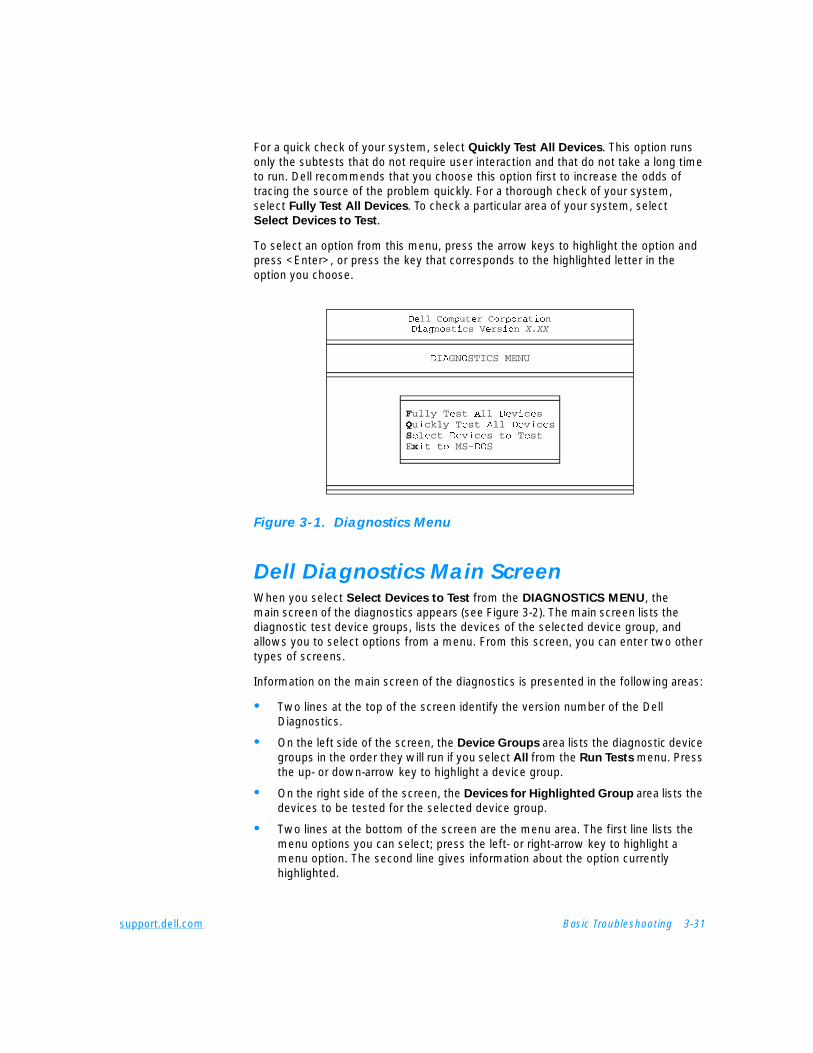
support.dell.com Basic Troubleshooting 3-31
For a quick check of your system, select Quickly Test All Devices. This option runs only the subtests that do not require user interaction and that do not take a long time to run. Dell recommends that you choose this option first to increase the odds of tracing the source of the problem quickly. For a thorough check of your system, select Fully Test All Devices. To check a particular area of your system, select Select Devices to Test.
To select an option from this menu, press the arrow keys to highlight the option and press <Enter>, or press the key that corresponds to the highlighted letter in the option you choose.
Figure 3-1. Diagnostics Menu
Dell Diagnostics Main ScreenWhen you select Select Devices to Test from the DIAGNOSTICS MENU, the main screen of the diagnostics appears (see Figure 3-2). The main screen lists the diagnostic test device groups, lists the devices of the selected device group, and allows you to select options from a menu. From this screen, you can enter two other types of screens.
Information on the main screen of the diagnostics is presented in the following areas:
• Two lines at the top of the screen identify the version number of the Dell Diagnostics.
• On the left side of the screen, the Device Groups area lists the diagnostic device groups in the order they will run if you select All from the Run Tests menu. Press the up- or down-arrow key to highlight a device group.
• On the right side of the screen, the Devices for Highlighted Group area lists the devices to be tested for the selected device group.
• Two lines at the bottom of the screen are the menu area. The first line lists the menu options you can select; press the left- or right-arrow key to highlight a menu option. The second line gives information about the option currently highlighted.
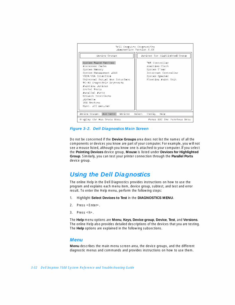
3-32 Dell Inspiron 7500 System Reference and Troubleshooting Guide
Figure 3-2. Dell Diagnostics Main Screen
Do not be concerned if the Device Groups area does not list the names of all the components or devices you know are part of your computer. For example, you will not see a mouse listed, although you know one is attached to your computer. If you select the Pointing Devices device group, Mouse is listed under Devices for Highlighted
Group. Similarly, you can test your printer connection through the Parallel Ports device group.
Using the Dell DiagnosticsThe online Help in the Dell Diagnostics provides instructions on how to use the program and explains each menu item, device group, subtest, and test and error result. To enter the Help menu, perform the following steps:
1. Highlight Select Devices to Test in the DIAGNOSTICS MENU.
2. Press <Enter>.
3. Press <h>.
The Help menu options are Menu, Keys, Device group, Device, Test, and Versions. The online Help also provides detailed descriptions of the devices that you are testing. The Help options are explained in the following subsections.
MenuMenu describes the main menu screen area, the device groups, and the different diagnostic menus and commands and provides instructions on how to use them.
support.dell.com Basic Troubleshooting 3-33
KeysKeys explains the functions of all the keystrokes that can be used in the Dell Diagnostics.
Device GroupDevice Group describes the device group that is presently highlighted in the Device
Groups list on the main menu screen. It also provides reasoning for using some tests.
DeviceDevice is the educational section of the online Help. It describes the function and purpose of the highlighted device in the Device Groups area. For example, the following information appears when you select Device for Diskette in the Device Groups list:
Diskette drive A:
The diskette disk drive device reads and writes data to and from diskettes. Diskettes are flexible recording media, sometimes contained in hard shells. Diskette recording capacities are small and access times are slow relative to hard disk drives, but they provide a convenient means of storing and transferring data.
TestTest provides a thorough explanation of the subtest highlighted for a selected device group. For example, the following description is provided for the Diskette Drive Seek
Test:
Diskette drive A: - Diskette Drive Seek Test
This test verifies the drive's ability to position its read/write heads. The test operates in two passes: first, seeking from the beginning to ending cylinders inclusively, and second, seeking alternately from the beginning to ending cylinders with convergence towards the middle.
VersionsVersions lists the version numbers of the subtests that are used by the Dell Diagnostics.

3-34 Dell Inspiron 7500 System Reference and Troubleshooting Guide
support.dell.com Installing System Software 4-1
C H A P T E R 4Installing System Software
This document explains how to install/reinstall Dell device drivers and utilities on your Dell computer running the Microsoft Windows 98 Second Edition operating system or the Microsoft Windows NT operating system. You may need to use this document under the following conditions:
• You are reinstalling the version of the Windows operating system that came with your computer, and you need to reinstall the drivers and utilities that Dell provides.
• You have a new hard-disk drive and you need to install all of the system software.
Installing the Windows 98 Operating SystemYou must install Windows 98 on the hard-disk drive before you install any device drivers.
1. Insert the Microsoft Boot Disk Windows 98 Series diskette into the diskette drive.
2. Restart the computer.
3. When the Microsoft Windows 98 Startup menu appears, insert the Microsoft Windows 98 CD into the CD-ROM or DVD-ROM drive.
4. Select Start Windows 98 Setup from CD-ROM and press <Enter>.
The Setup program runs ScanDisk to check your hard-disk drive.
5. When the hard-disk drive check is completed, type x to exit ScanDisk.
6. Follow the prompts on your screen to continue with the installation.
7. When prompted to create a start-up diskette, remove the Microsoft Boot Disk Windows 98 Series diskette, and click Next>.
4-2 Dell Inspiron 7500 System Reference and Troubleshooting Guide
8. Label a blank, high-density diskette as instructed, insert the diskette into the diskette drive, and then click OK.
9. Follow the prompts on your screen to complete the installation.
Installing Drivers and Utilities forWindows 98This section explains how to install/reinstall device drivers and utilities on your Dell computer running the Microsoft Windows 98 Second Edition operating system.
To install the system software, you need the following items:
• System Software CD
• CD-ROM or DVD-ROM drive installed in the media bay of the computer
• Microsoft Windows 98 Second Edition CD
• Microsoft Boot Disk Windows 98 Series diskette
NOTE: Verify that Windows 98 is already installed on the hard-disk drive before you install any device drivers. For instructions, see the preceding section, “Installing the Windows 98 Operating System.”
The following subsections describe the installation instructions for the drivers and utilities that are provided on the System Software CD for use with a system running the Windows 98 operating system.
Installing the Audio DriverThe audio driver allows you to customize the sound features of your computer.
1. Save and close any open files, and exit any open application programs.
2. Insert the System Software CD into the CD-ROM or DVD-ROM drive.
3. If the Welcome to Windows 98 screen appears, click the x in the upper-right corner of the screen to close it and continue with the installation.
4. Click the Start button, and then click Run.
5. In the Run dialog box, type x:\win98\audio\setup.exe, where x is the CD-ROM or DVD-ROM drive letter.
The CD-ROM or DVD-ROM drive letter is usually D.
6. Click OK.
7. At the Welcome screen, click Next>.
8. At the Main Menu, the Upgrade Drivers radio button is selected. Click Next>.
The audio files are copied to your hard-disk drive.
support.dell.com Installing System Software 4-3
9. When prompted, be sure that the Yes, I want to restart my computer now radio button is selected, and then click Finish.
The New Hardware Found window appears, the driver is installed, and the installation is completed.
Installing the Video DriverThe video driver controls features such as video resolution and color palette.
NOTE: If you need to use extended video modes, check the documentation that accompanied the application program to determine if the driver is provided. If it is not, contact the software manufacturer to get the necessary driver.
1. Save and close any open files, and exit any open application programs.
2. Insert the System Software CD into the CD-ROM or DVD-ROM drive.
3. If the Welcome to Windows 98 screen appears, click the x in the upper-right corner of the screen to close it and continue with the installation.
4. Click the Start button, and then click Run.
5. In the Run dialog box, type x:\win98\video\setup.exe, where x is the CD-ROM or DVD-ROM drive.
The CD-ROM or DVD-ROM drive letter is usually D.
6. Click OK.
7. When prompted to restart, click Finish>.
The computer restarts automatically.
NOTE: After the computer restarts, you may change the video resolution.
Installing the Touch Pad DriverThe touch pad driver controls features such as touch pad and mouse functions, scrolling, touch features, and sensitivity.
NOTE: When you are promoted to select a directory, Dell recommends using the default directory settings.
1. Save and close any open files, and exit any open application programs.
2. Insert the System Software CD into the CD-ROM or DVD-ROM drive.
3. If the Welcome to Windows 98 screen appears, click the x in the upper-right corner of the screen to close it and continue with the installation.
4. Click the Start button, and then click Run.

4-4 Dell Inspiron 7500 System Reference and Troubleshooting Guide
5. In the Run dialog box, type x:\win98\touchpad\english\setup.exe, where x is the CD-ROM or DVD-ROM drive letter.
If you are using a Japanese-language version of Windows 98, type x:\win98\touchpad\japanese\setup.exe, where x is the CD-ROM or DVD-ROM drive letter.
The CD-ROM or DVD-ROM drive letter is usually D.
NOTICE: Do not install the Japanese-language driver on a computer with a non-Japanese-language operating system.
6. Click OK.
7. At the Welcome screen, click Next>.
At the Choose Destination Location window, click Next>.
8. At the Start Copying Files window, click Next>.
The touch pad files are copied to your hard-disk drive.
9. At the Setup Complete window, be sure that the Yes, I want to restart my
computer now radio button is selected, and then click Finish.
The Information about your Touch Pad window appears. If you do no want this window to appear each time you start the computer, uncheck the box that says Show this message the next time Windows starts. Then click Close.
Installing the Internal Modem Driver (Optional)NOTE: The internal modem is not available in some regions.
The modem driver allows you to customize the operation of the optional internal modem.
If your computer has an internal modem, perform the following steps to install the driver:
1. Save and close any open files, and exit any open application programs.
2. Insert the System Software CD into the CD-ROM or DVD-ROM drive.
3. If the Welcome to Windows 98 screen appears, click the x in the upper-right corner of the screen to close it and continue with the installation.
4. Click the Start button, and then click Run.
5. In the Run dialog box, type x:\win98\modem\setup.exe, where x is the CD-ROM or DVD-ROM drive letter.
The CD-ROM or DVD-ROM drive letter is usually D.
6. Click OK.
support.dell.com Installing System Software 4-5
7. At the Welcome Screen, click Next>.
The internal modem files are copied to your hard-disk drive.
The New Hardware Found window appears, the driver is installed, and the installation is completed.
Installing the Software DVD Decoder (Optional)The DVD decoder driver allows you to play DVD movies on the computer.
NOTE: When you are promoted to select a directory, Dell recommends using the default directory settings.
1. Insert the Dell Inspiron 7500 Software DVD Decoder CD into the DVD-ROM drive.
2. Click the Start button, and then click Run.
3. In the Run dialog box, type x:\setup.exe, where x is the DVD-ROM drive letter.
The DVD-ROM drive letter is usually D.
4. Click OK.
5. The Welcome window appears. Click Next>.
6. At the Choose Destination Location screen, click Next>.
7. At the Select Program Folder screen, click Next>.
8. At the Start Copying Files screen, click Next>.
9. At the Setup Complete screen, be sure that the Yes, I want to restart my
computer now radio button is selected, and then click Finish.
The first time you play a DVD after installing this driver, you may be prompted to change the region setting.
Creating the Save-to-Disk Suspend FileAfter you have installed a new hard-disk drive or rebuilt a hard-disk drive that had corrupted software, use the phdisk.exe utility to create a save-to-disk suspend file after you partition the drive. When save-to-disk suspend mode is activated, all system data is stored in this file.
1. Save and close any open files, exit any open application programs, and restart the computer.
2. Insert the Microsoft Boot Disk Windows 98 Series diskette into the diskette drive.
4-6 Dell Inspiron 7500 System Reference and Troubleshooting Guide
3. When the Microsoft Windows 98 Startup Menu appears, press the down-arrow key to select 2. Start computer with CD-ROM support and press <Enter>.
4. When the A:\> prompt appears on the screen, insert the System Software CD into your CD-ROM or DVD-ROM drive.
5. At the A:\> prompt, type x:, where x is the drive letter for your CD-ROM or DVD-ROM drive, and press <Enter>.
The CD-ROM or DVD-ROM drive letter is usually D.
6. Type cd\utility\ and press <Enter>.
7. Type phdisk /create /file and press <Enter>.
NOTE: Make sure you insert a space before the slashes.
The utility calculates the size of the file in kilobytes (KB), based on the amount of system memory and video memory in your computer, and adds 2 megabytes (MB) to handle additional system requirements.
8. Follow the instructions on your screen to create the save-to-disk suspend file.
To check the size of the save-to-disk suspend file, type phdisk /info at the MS-DOS® prompt and press <Enter>.
To delete the save-to-disk suspend file, type phdisk /delete /file and press <Enter>.
9. Remove the Microsoft Boot Disk Windows 98 Series diskette, and press <Ctrl><Alt><Del> to restart the system.
Installing the System HelpThe Dell Inspiron system Help is available on the System Software CD. You can also access it from Dell’s support Web site (http://support.dell.com).
Installing Help From the CDTo install the system Help from the System Software CD, perform the following steps.
NOTE: You must copy the popup.ocx file into the Windows registry; otherwise, error messages may appear.
1. Insert the CD into the CD-ROM or DVD-ROM drive.
2. Double-click the My Computer icon, and then double-click the CD-ROM or DVD-ROM drive icon.
3. Double-click the Guide folder.
4. Right-click the popup.ocx file, and then right-click Copy.
5. Double-click the My Computer icon, and then double-click the C: drive icon.
support.dell.com Installing System Software 4-7
6. Double-click the Windows folder, then double-click the System folder, and then right-click Paste.
7. Click Start, and then click Run.
8. Type regsvr32 popup.ocx and then press <Enter>.
9. Click OK when a window indicates the file was successfully registered.
10. Double-click the My Computer icon, and then double-click the CD-ROM or DVD-ROM icon.
11. Double-click the Guide folder, and then double-click the appropriate language folder for the version of the Help you want to install.
12. Right-click and hold 7500help and drag it to the Windows desktop.
13. Release the right mouse button.
14. Left-click Copy Here.
15. Double-click the 7500help icon to access the system Help.
Downloading Help From the Support Web SiteTo download the system Help from http://support.dell.com, perform the following steps:
1. Click Support Your Dell.
2. Type your computer’s service tag sequence, if available, click Submit, and go to step 5.
If the service tag is not available, go to step 3.
3. Click Inspiron Notebooks.
4. Click 7500.
5. Click Dell Documents (Technical Information).
Follow the instructions on the page to save the file to your hard-disk drive.
6. Click System Help.
7. When prompted, you can save the Help file to your hard-disk drive.
4-8 Dell Inspiron 7500 System Reference and Troubleshooting Guide
Installing Drivers and Utilities for Windows NTThis section explains how to install/reinstall device drivers and utilities on your Dell portable computer running the Microsoft Windows NT 4.0 operating system.
NOTICE: You must install the Windows NT service pack before installing device drivers.
To install the system software, you need the following items:
• Microsoft Windows NT 4.0 CD
• Microsoft Windows NT 4.0 Service Pack 5 CD
• System Software CD
• CD-ROM drive (installed)
• One formatted diskette
The following subsections describe the drivers and utilities that are provided on the System Software CD.
NOTE: To install the drivers and utilities correctly, you must install them in the order presented in this document.
Creating the Save-to-Disk Suspend PartitionIf you have installed a new hard-disk drive or are rebuilding a hard-disk drive that had corrupted software, you must create a save-to-disk suspend partition before creating any other partitions (but after deleting any existing partitions). To create a save-to-disk suspend partition, perform the following steps:
1. Insert the Dell Diagnostics and Utilities for Inspiron 7500 diskette number 1 into the diskette drive and turn on the computer.
2. When the message Insert Delldiag diskette 2 of 4 in drive A:... appears, type C to exit to MS-DOS. Leave the Dell Diagnostics and Utilities for Inspiron 7500 diskette number 1 in the diskette drive.
3. At the A:> prompt, type phdisk /create /partition and press <Enter>.
NOTE: Make sure you insert a space before the slashes.
The utility calculates the size of the file in kilobytes (KB), based on the amount of system memory and video memory in your computer, and adds 2 megabytes (MB) to handle additional system requirements and creates a partition on the hard-disk drive to store the system state when put in the save-to-disk suspend mode.
4. Follow the instructions provided in your Windows NT documentation to install the operating system on the drive.
support.dell.com Installing System Software 4-9
Installing the Video DriverThe video driver controls features such as video resolution and color palette.
NOTE: If you need to use extended video modes, check the documentation that accompanied the application program to determine if the driver is provided. If it is not, contact the software manufacturer to get the necessary driver.
1. Save and close any open files, and exit any open application programs.
2. Insert the System Software CD into the CD-ROM or DVD-ROM drive.
3. Double-click the My Computer icon, and then double-click the CD-ROM drive icon.
4. Double-click the WinNT folder, then double-click the Video folder.
5. Dobule-click setup.exe.
6. When prompted to restart, click Finish>.
The computer restarts automatically.
NOTE: After the computer restarts, you may change the video resolution.
Changing Video Resolution1. After the computer restarts, log on as Administrator.
2. Click OK in the Invalid Display Settings dialog box.
3. In the Color palette area, highlight 65536 Colors. In the Desktop Area, drag the pointer to the right until 1024 by 768 pixels is shown. Make sure the Refresh
Frequency is set to the optimum setting of 60 Hertz.
4. Click Test.
5. Click OK.
A test bitmap appears for the selected resolution and color palette.
6. Click Yes if the expected results appear.
7. Click Apply to immediately accept these settings and configure your desktop.
8. Click OK to close the Display Properties dialog box.
Installing the Audio DriverThe audio driver allows you to customize the sound features of your computer.
1. Log on as Administrator.
2. Insert the System Software CD into the CD-ROM drive.
3. Click the Start button, and then click Run.
4-10 Dell Inspiron 7500 System Reference and Troubleshooting Guide
4. In the Run dialog box, type x:\winnt\audio\setup.exe, where x is the DVD-ROM drive letter.
5. Click OK.
6. At the Welcome screen, click Next>.
7. At the Main Menu, the Install radio button is selected. Click Next>.
The audio files are copied to your hard-disk drive.
8. When prompted, be sure that the Yes, I want to restart my computer now radio button is selected, and then click Finish.
Installing the Touch Pad DriverThe touch pad driver controls features such as touch pad and mouse functions, scrolling, touch features, and sensitivity.
1. Log on as Administrator.
2. Insert the System Software CD into the CD-ROM drive.
3. Double-click the My Computer icon, and then double-click the CD-ROM drive icon.
4. Double-click the WinNT folder, then double-click the Touchpad folder, and then double-click the English folder.
If you are using a Japanese-language version of Windows NT, double-click the WinNT folder, then double-click the Touchpad folder, and then double-click the Japanese folder.
NOTICE: Do not install the Japanese-language driver on a computer with a non-Japanese-language operating system.
5. Double-click Setup.
6. In the Welcome window, click Next>.
7. In the Important Information window, click Next>.
Another Important Information window appears recommending that you create or update an emergency repair diskette before you install the touch pad driver.
8. Ensure that the Run the Emergency Repair Disk utility before installing check box is selected, and then click Next>.
9. Click Next> to install the files in the default directory.
10. Click Next> to begin copying the files.
11. When prompted to create an emergency repair diskette, click Yes.
12. Label a blank diskette “Emergency Repair Diskette,” insert it into the diskette drive, and then click OK.

support.dell.com Installing System Software 4-11
13. Click OK at the dialog box regarding sensitive information.
14. After the appropriate files are copied onto the hard-disk drive and the emergency repair diskette is created, remove the Emergency Repair Diskette and select Yes,
I want to restart my computer now.
Do not remove the System Software CD.
15. Click Finish to exit the installation and restart your computer.
To prevent the Show this Dialog Box at Startup window from appearing when the computer restarts, remove the check from the check box.
Installing the Power Management Configuration UtilityThe power management configuration utility allows you to adjust the way the computer uses the battery. The Softex Power Management icon appears in the Control Panel after you install the utility.
1. Log on as Administrator.
2. Insert the System Software CD into the CD-ROM drive.
3. Double-click the My Computer icon, and then double-click the CD-ROM drive icon.
4. Double-click the WinNT folder, and then double-click the APM folder.
5. Double-click Setup.
The Softex Power Management Control Setup screen appears, and then the Softex Power Management Control Setup window displays the license agreement.
6. Read the agreement and click Accept.
NOTE: You must accept the license agreement to continue.
7. Click the button in the Softex Power Management Control Setup window to accept the default installation directory.
The Softex Power Management Control Setup window notifies you that the installation is complete.
8. Click OK.
9. Click Don’t Restart Now in the Softex Power Management Control Setup
window.
4-12 Dell Inspiron 7500 System Reference and Troubleshooting Guide
Installing the PC Card Configuration UtilityThe PC Card configuration utility allows you to view and change the properties of an installed PC Card. The Softex PC Card Controller icon appears in the Control Panel after you install the utility.
1. Remove any PC Card(s) from the PC Card slot and restart the computer.
2. Insert the System Software CD into the CD-ROM drive.
3. Double-click the My Computer icon, and then double-click the CD-ROM drive icon.
4. Double-click the WinNT folder, and then double-click the PCMCIA folder.
5. Double-click Setup.
The Softex PC Card Controller Setup screen appears, and then the Softex PC Card Controller Setup window displays the license agreement.
6. Read the agreement and click Accept.
NOTE: You must accept the license agreement to continue.
7. Click the button in the Softex PC Card Controller Setup window to accept the default installation directory.
The Softex PC Card Controller Setup window monitors the installation and displays a status bar.
The Creating Control Panel window appears and notifies you that the setup program will install the PC Card configuration in the Control Panel and that the Microsoft Windows PC Card (PCMCIA) icon will be disabled.
8. Click I Understand.
9. When the Softex PC Card Controller Setup window notifies you that the installation is complete, click OK.
The Reboot Now window appears.
10. Click Restart Now to restart the computer.
11. Log on as Administrator.
The Softex PC Card Controller Diagnostics window appears.
12. Click Next>, and then click Next> again to start the diagnostics utility.
13. When the Softex PC Card Controller Diagnostics window notifies you that the diagnostics are complete, click Finish.
14. Verify that the computer restarts.

support.dell.com Installing System Software 4-13
Installing the Internal Modem Driver (Optional)The modem driver allows you to customize the operation of your optional internal modem.
NOTICE: Do not install this driver if the computer does not have an internal modem installed.
NOTE: The internal modem is not available in all regions.
1. Log on as Administrator.
2. Insert the System Software CD into the CD-ROM drive.
3. Double-click the My Computer icon, and then double-click the CD-ROM drive icon.
4. Double-click the WinNT folder, and then double-click the Modem folder.
5. Double-click Setup.
The Installing Modem Drivers window appears.
6. At the Modem Installation window, click Next>.
7. When prompted, select Install new modem driver and components and click Next>.
8. When prompted, select the Yes, I want to restart my computer now check box and click Finish to restart the computer.
Installing the System HelpThe Dell Inspiron system Help is available on the System Software CD. You can also access it from Dell’s support Web site (http://support.dell.com).
NOTE: You must install Microsoft Internet Explorer 4.01 from the Microsoft Windows NT 4.0 Service Pack 5 CD prior to installing the system Help.
Installing Help From the CDTo install the system Help from the System Software CD, perform the following steps:
1. Insert the CD into the CD-ROM drive.
2. Double-click the My Computer icon, and then double-click the CD-ROM drive icon.
3. Double-click the Guide folder, and then double-click the appropriate language folder for the version of the Help you want to install.
4. Right-click and hold 7500help and drag it to the Windows desktop.
5. Release the right mouse button.
4-14 Dell Inspiron 7500 System Reference and Troubleshooting Guide
6. Left-click Copy Here.
7. Double-click the 7500help icon to access the system Help.
Downloading Help From the Support Web SiteTo download the system Help from http://support.dell.com, perform the following steps:
1. Click Support Your Dell.
2. Type your service tag sequence, if available, click Submit, and go to step 5.
If the service tag is not available, go to step 3.
3. Click Inspiron Notebooks.
4. Click 7500.
5. Click Dell Documents (Technical Information).
Follow the instructions on the page to save the file to your hard-disk drive.
6. Click System Help.
7. When prompted, you can save the system Help to your hard-disk drive.
Contacting DellDell’s technical assistance Web site (http://support.dell.com) provides driver and utility updates, as well as technical assistance with questions about your computer. In addition, if you have access to a computer with a modem and/or fax capabilities, you can access Dell’s TechConnect bulletin board service (BBS), AutoTech service, and TechFax service. Dell’s Web site also contains links to some of these services.
Dell regularly tests and officially releases new drivers and utilities for Inspiron computers. A list of the latest drivers and utilities is available at http://support.dell.com.
support.dell.com Getting Help 5-1
C H A P T E R 5Getting Help
This chapter describes the tools Dell provides to help you when you have a problem with your computer. It also tells you when and how to call Dell for technical or customer assistance.
Technical Assistance If you need assistance with a technical problem, perform the following steps:
1. Complete the troubleshooting checks in Chapter 3, “Basic Troubleshooting.”
2. Run the Dell Diagnostics as described in “Running the Dell Diagnostics” in Chapter 3.
3. Make a copy of the Diagnostics Checklist (found later in this chapter), and fill it out.
4. Use Dell’s extensive suite of online services available at Dell’s World Wide Web site (http://www.dell.comwww.dell.com) for help with installation and troubleshooting procedures.
For more information, refer to “World Wide Web on the Internet” found later in this chapter.
5. If the preceding steps have not resolved the problem and you need to talk to a Dell technician, call Dell’s technical support service.
When prompted by Dell’s automated telephone system, enter your Express Service Code to route the call directly to the proper support personnel. If you do not have an Express Service Code, open the Dell Accessories folder, double-click the Express Service Code icon, and follow the directions.
NOTES: The Express Service Code is shown on the bottom of the computer.
Dell’s Express Service Code system may not be available in all countries.
For instructions on using the technical support service, refer to “Technical Support Service” and “Before You Call” found later in this chapter.
5-2 Dell Inspiron 7500 System Reference and Troubleshooting Guide
Help ToolsDell provides a number of tools to assist you. These tools are described in the following subsections.
NOTE: Some of the following tools are not always available in all locations outside the continental U.S. Please call your local Dell representative for information on availability.
World Wide WebThe Internet is your most powerful tool for obtaining information about your computer and other Dell products. Through the Internet, you can access most of the services described in this chapter, including AutoTech, TechFax, order status, technical support, and product information.
From Dell’s World Wide Web home page (www.dell.com), click the Support icon, and click Support Your Dell. Enter your service tag number (or, if you have one, your Express Service Code) and click Submit. The service tag and Express Service Code are shown on the bottom of the computer.
You can also select support by clicking Inspiron and selecting your system by name.
Your system information is presented on the system support page, including the following tools and information:
• Technical information — Details on every aspect of your system, including hardware specifications.
• Self-diagnostic tool — A system-specific troubleshooting application for resolving many computer-related issues by following interactive flowcharts.
• Drivers, files, and utilities — The latest drivers and BIOS updates to keep your system functioning at its best.
• Component support — Technical information, documentation, and troubleshooting tips for different system components.
• Online Communications Center — Tool for submitting requests for both technical and non-technical information on Dell products. Avoid telephone delays by receiving an e-mail response to your request for information if your computer is not functioning properly or if you have questions regarding your computer’s hardware or operation.
Dell can be accessed electronically using the following addresses:
• World Wide Web
http://www.dell.com/
http://www.dell.com/ap/ (for Asian/Pacific countries only)
http://www.euro.dell.com (for Europe only)
support.dell.com Getting Help 5-3
• Anonymous file transfer protocol (FTP)
ftp.dell.com/
Log in as user: anonymous, and use your e-mail address as your password.
• Electronic Support Service
[email protected] (for Asian/Pacific countries only)
support.euro.dell.com (for Europe only)
• Electronic Quote Service
[email protected] (for Asian/Pacific countries only)
• Electronic Information Service
AutoTech ServiceDell’s automated technical support service—AutoTech—provides recorded answers to the questions most frequently asked by Dell customers.
When you call AutoTech, you use your touch-tone telephone to select the subjects that correspond to your questions. You can even interrupt an AutoTech session and continue the session later. The code number that the AutoTech service gives you allows you to continue your session where you ended it.
The AutoTech service is available 24 hours a day, seven days a week. You can also access this service through the technical support service. For the telephone number to call, refer to “Dell Contact Numbers” found later in this chapter.
TechFax ServiceDell takes full advantage of fax technology to serve you better. Twenty-four hours a day, seven days a week, you can call the Dell TechFax line toll-free for all kinds of technical information.
Using a touch-tone phone, you can select from a full directory of topics. The technical information you request is sent within minutes to the fax number you designate. For the TechFax telephone number to call, refer to “Dell Contact Numbers” found later in this chapter.
TechConnect BBS Use your modem to access Dell’s TechConnect bulletin board service (BBS) 24 hours a day, seven days a week. The service is menu-driven and fully interactive. The protocol parameters for the BBS are 1200 to 19.2K baud, 8 data bits, no parity, 1 stop bit.

5-4 Dell Inspiron 7500 System Reference and Troubleshooting Guide
Automated Order-Status SystemYou can call this automated service to check on the status of any Dell products that you have ordered. A recording prompts you for the information needed to locate and report on your order. For the telephone number to call, refer to “Dell Contact Numbers” found later in this chapter.
Technical Support ServiceDell’s industry-leading hardware technical-support service is available 24 hours a day, seven days a week, to answer your questions about Dell hardware.
Our technical support staff pride themselves on their track record: more than 90 percent of all problems and questions are taken care of in just one toll-free call, usually in less than 10 minutes. When you call, our experts can refer to records kept on your Dell system to better understand your particular question. Our technical support staff use computer-based diagnostics to provide fast, accurate answers to questions.
To contact Dell’s technical support service, first refer to the section titled “Before You Call” and then call the number for your country as listed in “Dell Contact Numbers” found later in this chapter.
Problems With Your Order If you have a problem with your order, such as missing parts, wrong parts, or incorrect billing, contact Dell Computer Corporation for customer assistance. Have your invoice or packing slip handy when you call. For the telephone number to call, refer to “Dell Contact Numbers” found later in this chapter.
Product InformationIf you need information about additional products available from Dell Computer Corporation, or if you would like to place an order, visit Dell’s World Wide Web site at http://www.dell.com/. For the telephone number to call to speak to a sales specialist, refer to “Dell Contact Numbers” found later in this chapter.
Returning Items for Warranty Repair or CreditDell’s technical support staff will work with you to solve any problem you may have with your computer. Sometimes, though, a part needs to be returned to Dell for repair or credit. Use the following procedure to prepare all items being returned:
1. Call Dell to obtain an authorization number, and write it clearly and prominently on the outside of the box.
For the telephone number to call, refer to “Dell Contact Numbers” found later in this chapter.
support.dell.com Getting Help 5-5
2. Include a copy of the invoice and a letter describing the reason for the return.
3. Include a copy of the Diagnostics Checklist indicating the tests you have run and any error messages reported by the Dell Diagnostics.
4. Include any accessories that belong with the item(s) being returned (power cables, software diskettes, guides, and so on) if the return is for credit.
5. Pack the equipment to be returned in the original (or equivalent) packing materials.
You are responsible for paying shipping expenses. You are also responsible for insuring any product returned, and you assume the risk of loss during shipment to Dell Computer Corporation. Collect-on-delivery (C.O.D.) packages are not accepted.
Returns that are missing any of the preceding requirements will be refused at our receiving dock and returned to you.
Before You CallNOTE: Have your Express Service Code ready when you call. The code helps Dell’s automated-support telephone system direct your call more efficiently.
Remember to fill out the Diagnostics Checklist (Figure 5-1). If possible, turn on your system before you call Dell for technical assistance and call from a telephone at or near the computer. You may be asked to type some commands at the keyboard, relay detailed information during operations, or try other troubleshooting steps possible only at the computer system itself. Make sure the system documentation is available.
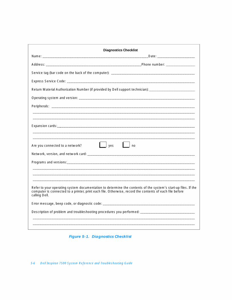
5-6 Dell Inspiron 7500 System Reference and Troubleshooting Guide
Figure 5-1. Diagnostics Checklist
Name: ______________________________________________________________Date: ______________________
Address: ________________________________________________________Phone number: _________________
Service tag (bar code on the back of the computer): _________________________________________________
Express Service Code: ___________________________________________________________________________
Return Material Authorization Number (if provided by Dell support technician): ___________________________
Operating system and version: ____________________________________________________________________
Peripherals: ____________________________________________________________________________________
_______________________________________________________________________________________________
_______________________________________________________________________________________________
Expansion cards:_________________________________________________________________________________
_______________________________________________________________________________________________
_______________________________________________________________________________________________
Are you connected to a network? yes no
Network, version, and network card: _______________________________________________________________
Programs and versions: ___________________________________________________________________________
_______________________________________________________________________________________________
_______________________________________________________________________________________________
_______________________________________________________________________________________________
Refer to your operating system documentation to determine the contents of the system’s start-up files. If the computer is connected to a printer, print each file. Otherwise, record the contents of each file before calling Dell.
Error message, beep code, or diagnostic code: ______________________________________________________
Description of problem and troubleshooting procedures you performed: ________________________________
_______________________________________________________________________________________________
_______________________________________________________________________________________________
Diagnostics Checklist
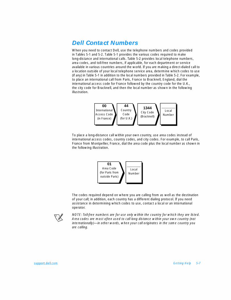
support.dell.com Getting Help 5-7
Dell Contact Numbers When you need to contact Dell, use the telephone numbers and codes provided in Tables 5-1 and 5-2. Table 5-1 provides the various codes required to make long-distance and international calls. Table 5-2 provides local telephone numbers, area codes, and toll-free numbers, if applicable, for each department or service available in various countries around the world. If you are making a direct-dialed call to a location outside of your local telephone service area, determine which codes to use (if any) in Table 5-1 in addition to the local numbers provided in Table 5-2. For example, to place an international call from Paris, France to Bracknell, England, dial the international access code for France followed by the country code for the U.K., the city code for Bracknell, and then the local number as shown in the following illustration.
To place a long-distance call within your own country, use area codes instead of international access codes, country codes, and city codes. For example, to call Paris, France from Montpellier, France, dial the area code plus the local number as shown in the following illustration.
The codes required depend on where you are calling from as well as the destination of your call; in addition, each country has a different dialing protocol. If you need assistance in determining which codes to use, contact a local or an international operator.
NOTE: Toll-free numbers are for use only within the country for which they are listed. Area codes are most often used to call long distance within your own country (not internationally)—in other words, when your call originates in the same country you are calling.
00International Access Code
(in France)
1344City Code (Bracknell)
________Local
Number
44Country
Code(for U.K.)
01Area Code
(for Paris from outside Paris)
________Local
Number

5-8 Dell Inspiron 7500 System Reference and Troubleshooting Guide
Table 5-1. International Dialing Codes
Country (City)InternationalAccess Code Country Code City Code
Australia (Sydney) 0011 61 2
Austria (Vienna) 900 43 1
Belgium (Brussels) 00 32 2
Brunei — 673 —
Canada (North York, Ontario) 011 — Not required
Chile (Santiago) — 56 2
China (Xiamen) — 86 592
Czech Republic (Prague) 00 420 2
Denmark (Horsholm) 009 45 Not required
Finland (Helsinki) 990 358 9
France (Paris) (Montpellier) 00 33 (1) (4)
Germany (Langen) 00 49 6103
Hong Kong 001 852 Not required
Ireland (Bray) 16 353 1
Italy (Milan) 00 39 2
Japan (Kawasaki) 001 81 44
Korea (Seoul) 001 82 2
Luxembourg 00 352 —
Macau — 853 Not required
Malaysia (Penang) 00 60 4
Mexico (Colonia Granada) 95 52 5
Netherlands (Amsterdam) 00 31 20
New Zealand 00 64 —
Norway (Lysaker) 095 47 Not required
Poland (Warsaw) 011 48 22
Singapore (Singapore) 005 65 Not required
South Africa (Johannesburg) 09/091 27 11
Spain (Madrid) 07 34 91
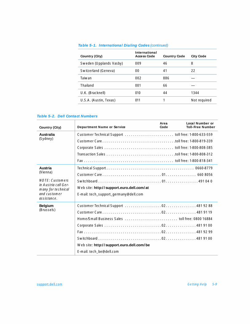
support.dell.com Getting Help 5-9
Sweden (Upplands Vasby) 009 46 8
Switzerland (Geneva) 00 41 22
Taiwan 002 886 —
Thailand 001 66 —
U.K. (Bracknell) 010 44 1344
U.S.A. (Austin, Texas) 011 1 Not required
Table 5-1. International Dialing Codes (continued)
Country (City)InternationalAccess Code Country Code City Code
Table 5-2. Dell Contact Numbers
Country (City)Area Local Number or
Department Name or Service Code Toll-Free Number
Australia(Sydney)
Customer Technical Support . . . . . . . . . . . . . . . . . . . . . . . . toll free: 1-800-633-559
Customer Care . . . . . . . . . . . . . . . . . . . . . . . . . . . . . . . . . . . .toll free: 1-800-819-339
Corporate Sales . . . . . . . . . . . . . . . . . . . . . . . . . . . . . . . . . . toll free: 1-800-808-385
Transaction Sales . . . . . . . . . . . . . . . . . . . . . . . . . . . . . . . . . .toll free: 1-800-808-312
Fax . . . . . . . . . . . . . . . . . . . . . . . . . . . . . . . . . . . . . . . . . . . . toll free: 1-800-818-341
Austria(Vienna)
NOTE: Customers in Austria call Ger-many for technical and customer assistance.
Technical Support . . . . . . . . . . . . . . . . . . . . . . . . . . . . . . . . . . . . . . . . . . . 0660-8779
Customer Care . . . . . . . . . . . . . . . . . . . . . . . . . . . . . 01. . . . . . . . . . . . . . . 660 8056
Switchboard . . . . . . . . . . . . . . . . . . . . . . . . . . . . . . . 01. . . . . . . . . . . . . . . . 491 04 0
Web site: http://support.euro.dell.com/at
E-mail: [email protected]
Belgium(Brussels)
Customer Technical Support . . . . . . . . . . . . . . . . . . 02. . . . . . . . . . . . . . . 481 92 88
Customer Care . . . . . . . . . . . . . . . . . . . . . . . . . . . . . 02. . . . . . . . . . . . . . . 481 91 19
Home/Small Business Sales . . . . . . . . . . . . . . . . . . . . . . . . . . toll free: 0800 16884
Corporate Sales . . . . . . . . . . . . . . . . . . . . . . . . . . . . 02. . . . . . . . . . . . . . . 481 91 00
Fax . . . . . . . . . . . . . . . . . . . . . . . . . . . . . . . . . . . . . . 02. . . . . . . . . . . . . . . 481 92 99
Switchboard . . . . . . . . . . . . . . . . . . . . . . . . . . . . . . . 02. . . . . . . . . . . . . . . 481 91 00
Web site: http://support.euro.dell.com/be
E-mail: [email protected]
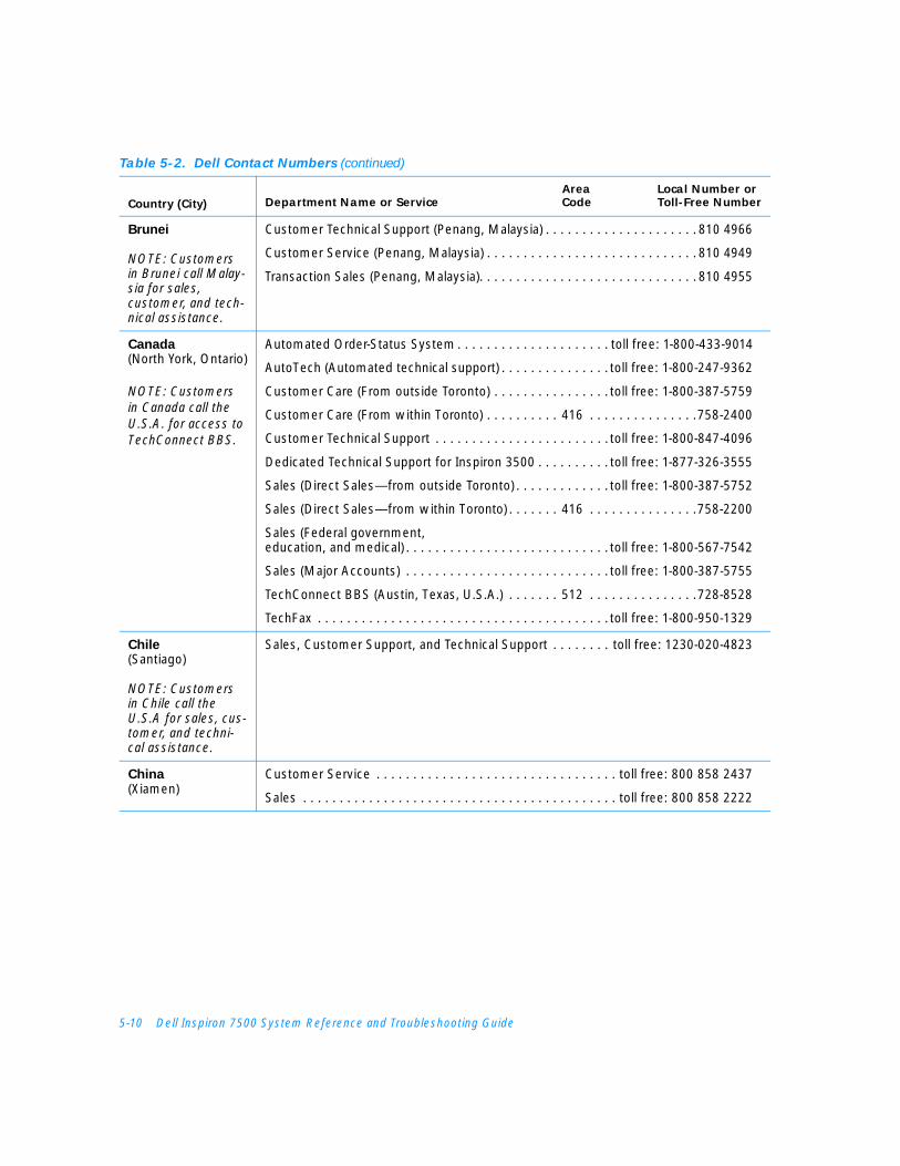
5-10 Dell Inspiron 7500 System Reference and Troubleshooting Guide
Brunei
NOTE: Customers in Brunei call Malay-sia for sales, customer, and tech-nical assistance.
Customer Technical Support (Penang, Malaysia) . . . . . . . . . . . . . . . . . . . . . 810 4966
Customer Service (Penang, Malaysia) . . . . . . . . . . . . . . . . . . . . . . . . . . . . . 810 4949
Transaction Sales (Penang, Malaysia). . . . . . . . . . . . . . . . . . . . . . . . . . . . . . 810 4955
Canada(North York, Ontario)
NOTE: Customers in Canada call theU.S.A. for access to TechConnect BBS.
Automated Order-Status System . . . . . . . . . . . . . . . . . . . . . toll free: 1-800-433-9014
AutoTech (Automated technical support) . . . . . . . . . . . . . . . toll free: 1-800-247-9362
Customer Care (From outside Toronto) . . . . . . . . . . . . . . . . toll free: 1-800-387-5759
Customer Care (From within Toronto) . . . . . . . . . . 416 . . . . . . . . . . . . . . .758-2400
Customer Technical Support . . . . . . . . . . . . . . . . . . . . . . . . toll free: 1-800-847-4096
Dedicated Technical Support for Inspiron 3500 . . . . . . . . . . toll free: 1-877-326-3555
Sales (Direct Sales—from outside Toronto) . . . . . . . . . . . . . toll free: 1-800-387-5752
Sales (Direct Sales—from within Toronto) . . . . . . . 416 . . . . . . . . . . . . . . .758-2200
Sales (Federal government, education, and medical) . . . . . . . . . . . . . . . . . . . . . . . . . . . . toll free: 1-800-567-7542
Sales (Major Accounts) . . . . . . . . . . . . . . . . . . . . . . . . . . . . toll free: 1-800-387-5755
TechConnect BBS (Austin, Texas, U.S.A.) . . . . . . . 512 . . . . . . . . . . . . . . .728-8528
TechFax . . . . . . . . . . . . . . . . . . . . . . . . . . . . . . . . . . . . . . . . toll free: 1-800-950-1329
Chile(Santiago)
NOTE: Customers in Chile call the U.S.A for sales, cus-tomer, and techni-cal assistance.
Sales, Customer Support, and Technical Support . . . . . . . . toll free: 1230-020-4823
China(Xiamen)
Customer Service . . . . . . . . . . . . . . . . . . . . . . . . . . . . . . . . . toll free: 800 858 2437
Sales . . . . . . . . . . . . . . . . . . . . . . . . . . . . . . . . . . . . . . . . . . . toll free: 800 858 2222
Table 5-2. Dell Contact Numbers (continued)
Country (City)Area Local Number or
Department Name or Service Code Toll-Free Number
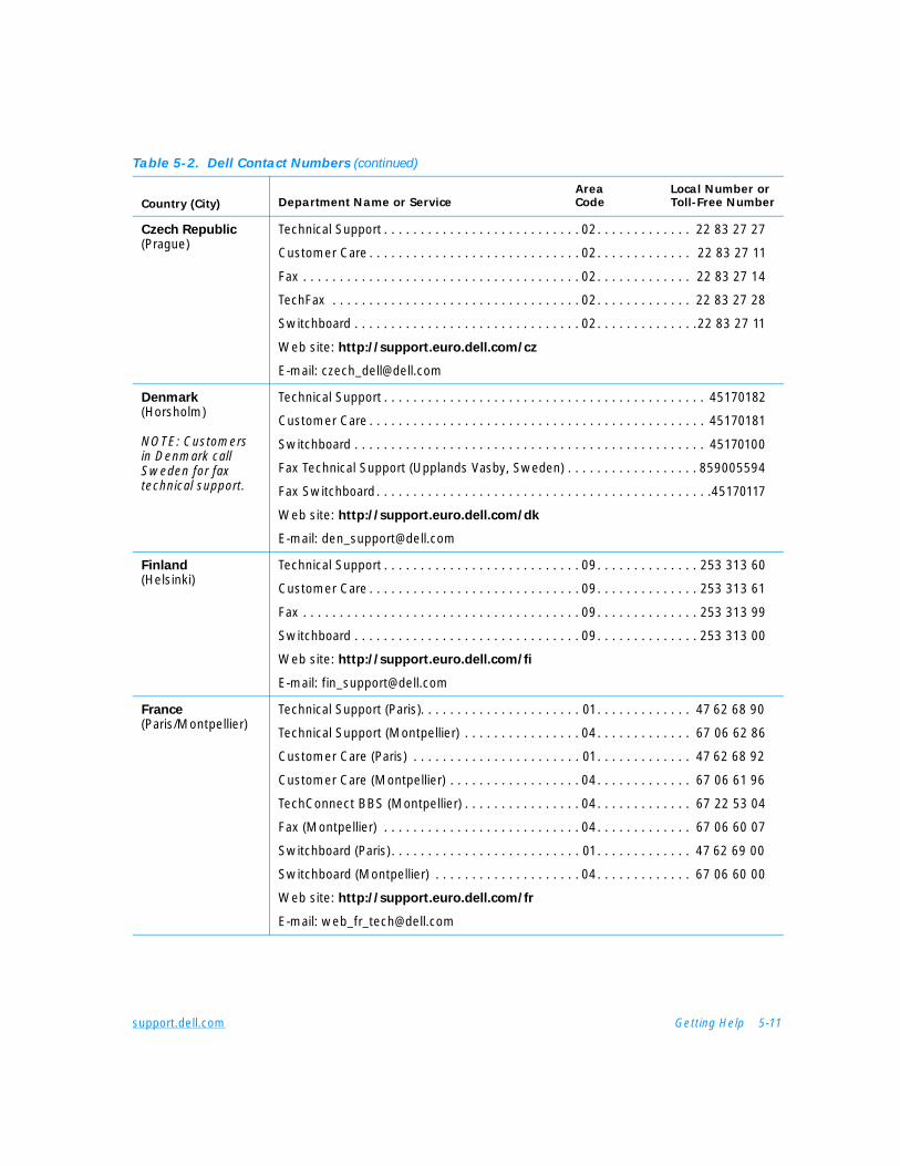
support.dell.com Getting Help 5-11
Czech Republic(Prague)
Technical Support . . . . . . . . . . . . . . . . . . . . . . . . . . . 02. . . . . . . . . . . . . 22 83 27 27
Customer Care . . . . . . . . . . . . . . . . . . . . . . . . . . . . . 02. . . . . . . . . . . . . 22 83 27 11
Fax . . . . . . . . . . . . . . . . . . . . . . . . . . . . . . . . . . . . . . 02. . . . . . . . . . . . . 22 83 27 14
TechFax . . . . . . . . . . . . . . . . . . . . . . . . . . . . . . . . . . 02. . . . . . . . . . . . . 22 83 27 28
Switchboard . . . . . . . . . . . . . . . . . . . . . . . . . . . . . . . 02. . . . . . . . . . . . . .22 83 27 11
Web site: http://support.euro.dell.com/cz
E-mail: [email protected]
Denmark(Horsholm)
NOTE: Customers in Denmark call Sweden for fax technical support.
Technical Support . . . . . . . . . . . . . . . . . . . . . . . . . . . . . . . . . . . . . . . . . . . . 45170182
Customer Care . . . . . . . . . . . . . . . . . . . . . . . . . . . . . . . . . . . . . . . . . . . . . . 45170181
Switchboard . . . . . . . . . . . . . . . . . . . . . . . . . . . . . . . . . . . . . . . . . . . . . . . . 45170100
Fax Technical Support (Upplands Vasby, Sweden) . . . . . . . . . . . . . . . . . . 859005594
Fax Switchboard. . . . . . . . . . . . . . . . . . . . . . . . . . . . . . . . . . . . . . . . . . . . . .45170117
Web site: http://support.euro.dell.com/dk
E-mail: [email protected]
Finland(Helsinki)
Technical Support . . . . . . . . . . . . . . . . . . . . . . . . . . . 09. . . . . . . . . . . . . . 253 313 60
Customer Care . . . . . . . . . . . . . . . . . . . . . . . . . . . . . 09. . . . . . . . . . . . . . 253 313 61
Fax . . . . . . . . . . . . . . . . . . . . . . . . . . . . . . . . . . . . . . 09. . . . . . . . . . . . . . 253 313 99
Switchboard . . . . . . . . . . . . . . . . . . . . . . . . . . . . . . . 09. . . . . . . . . . . . . . 253 313 00
Web site: http://support.euro.dell.com/fi
E-mail: [email protected]
France(Paris/Montpellier)
Technical Support (Paris). . . . . . . . . . . . . . . . . . . . . . 01. . . . . . . . . . . . . 47 62 68 90
Technical Support (Montpellier) . . . . . . . . . . . . . . . . 04. . . . . . . . . . . . . 67 06 62 86
Customer Care (Paris) . . . . . . . . . . . . . . . . . . . . . . . 01. . . . . . . . . . . . . 47 62 68 92
Customer Care (Montpellier) . . . . . . . . . . . . . . . . . . 04. . . . . . . . . . . . . 67 06 61 96
TechConnect BBS (Montpellier) . . . . . . . . . . . . . . . . 04. . . . . . . . . . . . . 67 22 53 04
Fax (Montpellier) . . . . . . . . . . . . . . . . . . . . . . . . . . . 04. . . . . . . . . . . . . 67 06 60 07
Switchboard (Paris). . . . . . . . . . . . . . . . . . . . . . . . . . 01. . . . . . . . . . . . . 47 62 69 00
Switchboard (Montpellier) . . . . . . . . . . . . . . . . . . . . 04. . . . . . . . . . . . . 67 06 60 00
Web site: http://support.euro.dell.com/fr
E-mail: [email protected]
Table 5-2. Dell Contact Numbers (continued)
Country (City)Area Local Number or
Department Name or Service Code Toll-Free Number
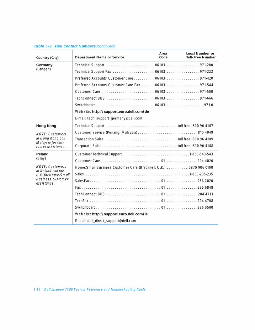
5-12 Dell Inspiron 7500 System Reference and Troubleshooting Guide
Germany(Langen)
Technical Support. . . . . . . . . . . . . . . . . . . . . . . . 06103 . . . . . . . . . . . . . . . . 971-200
Technical Support Fax . . . . . . . . . . . . . . . . . . . . 06103 . . . . . . . . . . . . . . . . 971-222
Preferred Accounts Customer Care . . . . . . . . . . 06103 . . . . . . . . . . . . . . . . 971-420
Preferred Accounts Customer Care Fax . . . . . . 06103 . . . . . . . . . . . . . . . . 971-544
Customer Care. . . . . . . . . . . . . . . . . . . . . . . . . . 06103 . . . . . . . . . . . . . . . . 971-500
TechConnect BBS . . . . . . . . . . . . . . . . . . . . . . . 06103 . . . . . . . . . . . . . . . . 971-666
Switchboard . . . . . . . . . . . . . . . . . . . . . . . . . . . . 06103 . . . . . . . . . . . . . . . . . . 971-0
Web site: http://support.euro.dell.com/de
E-mail: [email protected]
Hong Kong
NOTE: Customers in Hong Kong call Malaysia for cus-tomer assistance.
Technical Support. . . . . . . . . . . . . . . . . . . . . . . . . . . . . . . . . . . toll free: 800 96 4107
Customer Service (Penang, Malaysia) . . . . . . . . . . . . . . . . . . . . . . . . . . . . . 810 4949
Transaction Sales . . . . . . . . . . . . . . . . . . . . . . . . . . . . . . . . . . . toll free: 800 96 4109
Corporate Sales . . . . . . . . . . . . . . . . . . . . . . . . . . . . . . . . . . . . toll free: 800 96 4108
Ireland(Bray)
NOTE: Customers in Ireland call the U.K. for Home/Small Business customer assistance.
Customer Technical Support . . . . . . . . . . . . . . . . . . . . . . . . . . . . . . . . 1-850-543-543
Customer Care. . . . . . . . . . . . . . . . . . . . . . . . . . . . . 01 . . . . . . . . . . . . . . .204 4026
Home/Small Business Customer Care (Bracknell, U.K.) . . . . . . . . . . 0870 906 0100
Sales . . . . . . . . . . . . . . . . . . . . . . . . . . . . . . . . . . . . . . . . . . . . . . . . . . 1-850-235-235
SalesFax. . . . . . . . . . . . . . . . . . . . . . . . . . . . . . . . . . 01 . . . . . . . . . . . . . . .286 2020
Fax . . . . . . . . . . . . . . . . . . . . . . . . . . . . . . . . . . . . . . 01 . . . . . . . . . . . . . . .286 6848
TechConnect BBS . . . . . . . . . . . . . . . . . . . . . . . . . . 01 . . . . . . . . . . . . . . . 204 4711
TechFax . . . . . . . . . . . . . . . . . . . . . . . . . . . . . . . . . . 01 . . . . . . . . . . . . . . .204 4708
Switchboard . . . . . . . . . . . . . . . . . . . . . . . . . . . . . . . 01 . . . . . . . . . . . . . . .286 0500
Web site: http://support.euro.dell.com/ie
E-mail: [email protected]
Table 5-2. Dell Contact Numbers (continued)
Country (City)Area Local Number or
Department Name or Service Code Toll-Free Number
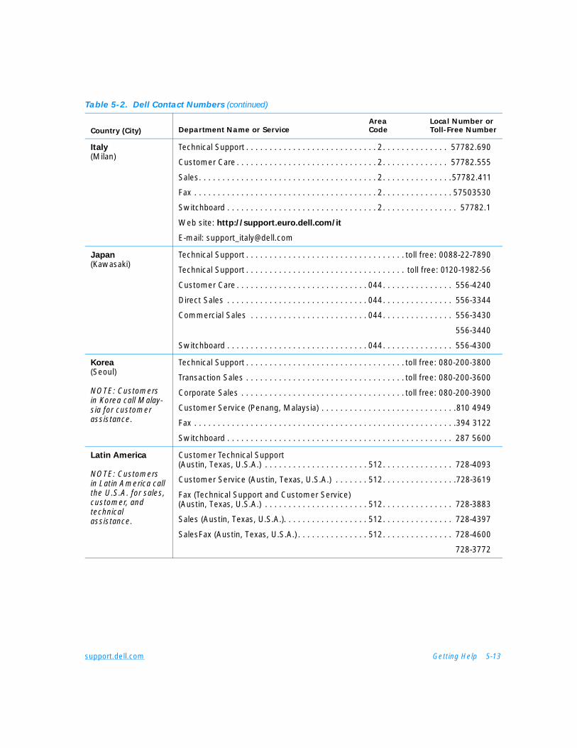
support.dell.com Getting Help 5-13
Italy(Milan)
Technical Support . . . . . . . . . . . . . . . . . . . . . . . . . . . . 2. . . . . . . . . . . . . . 57782.690
Customer Care . . . . . . . . . . . . . . . . . . . . . . . . . . . . . . 2. . . . . . . . . . . . . . 57782.555
Sales. . . . . . . . . . . . . . . . . . . . . . . . . . . . . . . . . . . . . . 2. . . . . . . . . . . . . . .57782.411
Fax . . . . . . . . . . . . . . . . . . . . . . . . . . . . . . . . . . . . . . . 2. . . . . . . . . . . . . . . 57503530
Switchboard . . . . . . . . . . . . . . . . . . . . . . . . . . . . . . . . 2. . . . . . . . . . . . . . . . 57782.1
Web site: http://support.euro.dell.com/it
E-mail: [email protected]
Japan(Kawasaki)
Technical Support . . . . . . . . . . . . . . . . . . . . . . . . . . . . . . . . . . toll free: 0088-22-7890
Technical Support . . . . . . . . . . . . . . . . . . . . . . . . . . . . . . . . . . toll free: 0120-1982-56
Customer Care . . . . . . . . . . . . . . . . . . . . . . . . . . . . 044. . . . . . . . . . . . . . . 556-4240
Direct Sales . . . . . . . . . . . . . . . . . . . . . . . . . . . . . . 044. . . . . . . . . . . . . . . 556-3344
Commercial Sales . . . . . . . . . . . . . . . . . . . . . . . . . 044. . . . . . . . . . . . . . . 556-3430
556-3440
Switchboard . . . . . . . . . . . . . . . . . . . . . . . . . . . . . . 044. . . . . . . . . . . . . . . 556-4300
Korea(Seoul)
NOTE: Customers in Korea call Malay-sia for customer assistance.
Technical Support . . . . . . . . . . . . . . . . . . . . . . . . . . . . . . . . . . toll free: 080-200-3800
Transaction Sales . . . . . . . . . . . . . . . . . . . . . . . . . . . . . . . . . . toll free: 080-200-3600
Corporate Sales . . . . . . . . . . . . . . . . . . . . . . . . . . . . . . . . . . . toll free: 080-200-3900
Customer Service (Penang, Malaysia) . . . . . . . . . . . . . . . . . . . . . . . . . . . . .810 4949
Fax . . . . . . . . . . . . . . . . . . . . . . . . . . . . . . . . . . . . . . . . . . . . . . . . . . . . . . . .394 3122
Switchboard . . . . . . . . . . . . . . . . . . . . . . . . . . . . . . . . . . . . . . . . . . . . . . . . 287 5600
Latin America
NOTE: Customers in Latin America call the U.S.A. for sales, customer, and technical assistance.
Customer Technical Support (Austin, Texas, U.S.A.) . . . . . . . . . . . . . . . . . . . . . . 512. . . . . . . . . . . . . . . 728-4093
Customer Service (Austin, Texas, U.S.A.) . . . . . . . 512. . . . . . . . . . . . . . . .728-3619
Fax (Technical Support and Customer Service) (Austin, Texas, U.S.A.) . . . . . . . . . . . . . . . . . . . . . . 512. . . . . . . . . . . . . . . 728-3883
Sales (Austin, Texas, U.S.A.). . . . . . . . . . . . . . . . . . 512. . . . . . . . . . . . . . . 728-4397
SalesFax (Austin, Texas, U.S.A.) . . . . . . . . . . . . . . . 512. . . . . . . . . . . . . . . 728-4600
728-3772
Table 5-2. Dell Contact Numbers (continued)
Country (City)Area Local Number or
Department Name or Service Code Toll-Free Number
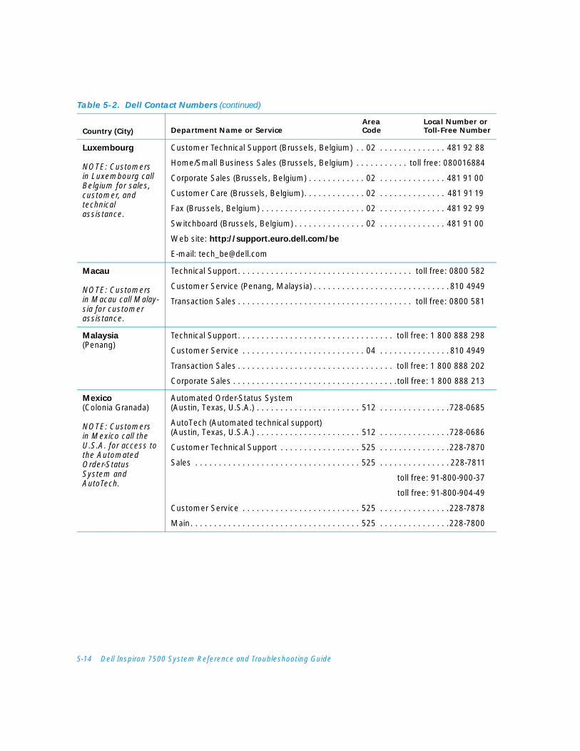
5-14 Dell Inspiron 7500 System Reference and Troubleshooting Guide
Luxembourg
NOTE: Customers in Luxembourg call Belgium for sales, customer, and technical assistance.
Customer Technical Support (Brussels, Belgium) . . 02 . . . . . . . . . . . . . . 481 92 88
Home/Small Business Sales (Brussels, Belgium) . . . . . . . . . . . toll free: 080016884
Corporate Sales (Brussels, Belgium) . . . . . . . . . . . . 02 . . . . . . . . . . . . . . 481 91 00
Customer Care (Brussels, Belgium). . . . . . . . . . . . . 02 . . . . . . . . . . . . . . 481 91 19
Fax (Brussels, Belgium) . . . . . . . . . . . . . . . . . . . . . . 02 . . . . . . . . . . . . . . 481 92 99
Switchboard (Brussels, Belgium) . . . . . . . . . . . . . . . 02 . . . . . . . . . . . . . . 481 91 00
Web site: http://support.euro.dell.com/be
E-mail: [email protected]
Macau
NOTE: Customers in Macau call Malay-sia for customer assistance.
Technical Support. . . . . . . . . . . . . . . . . . . . . . . . . . . . . . . . . . . . . toll free: 0800 582
Customer Service (Penang, Malaysia) . . . . . . . . . . . . . . . . . . . . . . . . . . . . . 810 4949
Transaction Sales . . . . . . . . . . . . . . . . . . . . . . . . . . . . . . . . . . . . . toll free: 0800 581
Malaysia(Penang)
Technical Support. . . . . . . . . . . . . . . . . . . . . . . . . . . . . . . . . toll free: 1 800 888 298
Customer Service . . . . . . . . . . . . . . . . . . . . . . . . . . 04 . . . . . . . . . . . . . . . 810 4949
Transaction Sales . . . . . . . . . . . . . . . . . . . . . . . . . . . . . . . . . toll free: 1 800 888 202
Corporate Sales . . . . . . . . . . . . . . . . . . . . . . . . . . . . . . . . . . .toll free: 1 800 888 213
Mexico(Colonia Granada)
NOTE: Customers in Mexico call the U.S.A. for access to the Automated Order-Status System and AutoTech.
Automated Order-Status System (Austin, Texas, U.S.A.) . . . . . . . . . . . . . . . . . . . . . . 512 . . . . . . . . . . . . . . .728-0685
AutoTech (Automated technical support)(Austin, Texas, U.S.A.) . . . . . . . . . . . . . . . . . . . . . . 512 . . . . . . . . . . . . . . .728-0686
Customer Technical Support . . . . . . . . . . . . . . . . . 525 . . . . . . . . . . . . . . .228-7870
Sales . . . . . . . . . . . . . . . . . . . . . . . . . . . . . . . . . . . 525 . . . . . . . . . . . . . . . 228-7811
toll free: 91-800-900-37
toll free: 91-800-904-49
Customer Service . . . . . . . . . . . . . . . . . . . . . . . . . 525 . . . . . . . . . . . . . . .228-7878
Main. . . . . . . . . . . . . . . . . . . . . . . . . . . . . . . . . . . . 525 . . . . . . . . . . . . . . .228-7800
Table 5-2. Dell Contact Numbers (continued)
Country (City)Area Local Number or
Department Name or Service Code Toll-Free Number
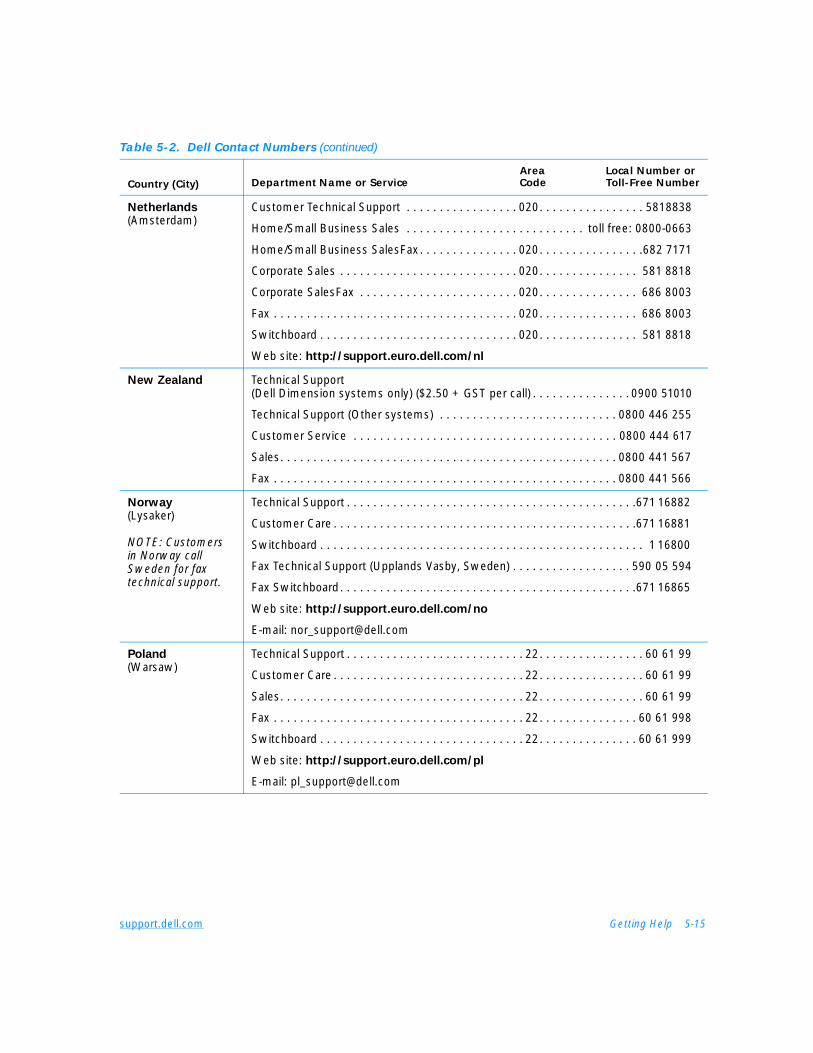
support.dell.com Getting Help 5-15
Netherlands(Amsterdam)
Customer Technical Support . . . . . . . . . . . . . . . . . 020. . . . . . . . . . . . . . . . 5818838
Home/Small Business Sales . . . . . . . . . . . . . . . . . . . . . . . . . . . toll free: 0800-0663
Home/Small Business SalesFax. . . . . . . . . . . . . . . 020. . . . . . . . . . . . . . . .682 7171
Corporate Sales . . . . . . . . . . . . . . . . . . . . . . . . . . . 020. . . . . . . . . . . . . . . 581 8818
Corporate SalesFax . . . . . . . . . . . . . . . . . . . . . . . . 020. . . . . . . . . . . . . . . 686 8003
Fax . . . . . . . . . . . . . . . . . . . . . . . . . . . . . . . . . . . . . 020. . . . . . . . . . . . . . . 686 8003
Switchboard . . . . . . . . . . . . . . . . . . . . . . . . . . . . . . 020. . . . . . . . . . . . . . . 581 8818
Web site: http://support.euro.dell.com/nl
New Zealand Technical Support (Dell Dimension systems only) ($2.50 + GST per call) . . . . . . . . . . . . . . . 0900 51010
Technical Support (Other systems) . . . . . . . . . . . . . . . . . . . . . . . . . . . 0800 446 255
Customer Service . . . . . . . . . . . . . . . . . . . . . . . . . . . . . . . . . . . . . . . . 0800 444 617
Sales. . . . . . . . . . . . . . . . . . . . . . . . . . . . . . . . . . . . . . . . . . . . . . . . . . . 0800 441 567
Fax . . . . . . . . . . . . . . . . . . . . . . . . . . . . . . . . . . . . . . . . . . . . . . . . . . . . 0800 441 566
Norway(Lysaker)
NOTE: Customers in Norway call Sweden for fax technical support.
Technical Support . . . . . . . . . . . . . . . . . . . . . . . . . . . . . . . . . . . . . . . . . . . .671 16882
Customer Care . . . . . . . . . . . . . . . . . . . . . . . . . . . . . . . . . . . . . . . . . . . . . .671 16881
Switchboard . . . . . . . . . . . . . . . . . . . . . . . . . . . . . . . . . . . . . . . . . . . . . . . . . 1 16800
Fax Technical Support (Upplands Vasby, Sweden) . . . . . . . . . . . . . . . . . . 590 05 594
Fax Switchboard. . . . . . . . . . . . . . . . . . . . . . . . . . . . . . . . . . . . . . . . . . . . .671 16865
Web site: http://support.euro.dell.com/no
E-mail: [email protected]
Poland(Warsaw)
Technical Support . . . . . . . . . . . . . . . . . . . . . . . . . . . 22. . . . . . . . . . . . . . . . 60 61 99
Customer Care . . . . . . . . . . . . . . . . . . . . . . . . . . . . . 22. . . . . . . . . . . . . . . . 60 61 99
Sales. . . . . . . . . . . . . . . . . . . . . . . . . . . . . . . . . . . . . 22. . . . . . . . . . . . . . . . 60 61 99
Fax . . . . . . . . . . . . . . . . . . . . . . . . . . . . . . . . . . . . . . 22. . . . . . . . . . . . . . . 60 61 998
Switchboard . . . . . . . . . . . . . . . . . . . . . . . . . . . . . . . 22. . . . . . . . . . . . . . . 60 61 999
Web site: http://support.euro.dell.com/pl
E-mail: [email protected]
Table 5-2. Dell Contact Numbers (continued)
Country (City)Area Local Number or
Department Name or Service Code Toll-Free Number
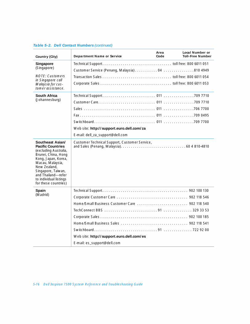
5-16 Dell Inspiron 7500 System Reference and Troubleshooting Guide
Singapore(Singapore)
NOTE: Customers in Singapore call Malaysia for cus-tomer assistance.
Technical Support. . . . . . . . . . . . . . . . . . . . . . . . . . . . . . . . . . toll free: 800 6011 051
Customer Service (Penang, Malaysia) . . . . . . . . . . . 04 . . . . . . . . . . . . . . . 810 4949
Transaction Sales . . . . . . . . . . . . . . . . . . . . . . . . . . . . . . . . . . toll free: 800 6011 054
Corporate Sales . . . . . . . . . . . . . . . . . . . . . . . . . . . . . . . . . . . toll free: 800 6011 053
South Africa(Johannesburg)
Technical Support. . . . . . . . . . . . . . . . . . . . . . . . . . 011 . . . . . . . . . . . . . . . 709 7710
Customer Care. . . . . . . . . . . . . . . . . . . . . . . . . . . . 011 . . . . . . . . . . . . . . . 709 7710
Sales . . . . . . . . . . . . . . . . . . . . . . . . . . . . . . . . . . . 011 . . . . . . . . . . . . . . .706 7700
Fax . . . . . . . . . . . . . . . . . . . . . . . . . . . . . . . . . . . . . 011 . . . . . . . . . . . . . . .709 0495
Switchboard . . . . . . . . . . . . . . . . . . . . . . . . . . . . . . 011 . . . . . . . . . . . . . . .709 7700
Web site: http://support.euro.dell.com/za
E-mail: [email protected]
Southeast Asian/Pacific Countries(excluding Australia, Brunei, China, Hong Kong, Japan, Korea, Macau, Malaysia, New Zealand, Singapore, Taiwan, and Thailand—refer to individual listings for these countries)
Customer Technical Support, Customer Service, and Sales (Penang, Malaysia). . . . . . . . . . . . . . . . . . . . . . . . . . . . . . . . 60 4 810-4810
Spain(Madrid)
Technical Support. . . . . . . . . . . . . . . . . . . . . . . . . . . . . . . . . . . . . . . . . . 902 100 130
Corporate Customer Care . . . . . . . . . . . . . . . . . . . . . . . . . . . . . . . . . . . 902 118 546
Home/Small Business Customer Care . . . . . . . . . . . . . . . . . . . . . . . . . 902 118 540
TechConnect BBS . . . . . . . . . . . . . . . . . . . . . . . . . . 91 . . . . . . . . . . . . . . 329 33 53
Corporate Sales . . . . . . . . . . . . . . . . . . . . . . . . . . . . . . . . . . . . . . . . . . . 902 100 185
Home/Small Business Sales . . . . . . . . . . . . . . . . . . . . . . . . . . . . . . . . . 902 118 541
Switchboard . . . . . . . . . . . . . . . . . . . . . . . . . . . . . . . 91 . . . . . . . . . . . . . . 722 92 00
Web site: http://support.euro.dell.com/es
E-mail: [email protected]
Table 5-2. Dell Contact Numbers (continued)
Country (City)Area Local Number or
Department Name or Service Code Toll-Free Number

support.dell.com Getting Help 5-17
Sweden(Upplands Vasby)
Technical Support . . . . . . . . . . . . . . . . . . . . . . . . . . . 08. . . . . . . . . . . . . . 590 05 199
Customer Care . . . . . . . . . . . . . . . . . . . . . . . . . . . . . 08. . . . . . . . . . . . . . 590 05 169
Fax Technical Support. . . . . . . . . . . . . . . . . . . . . . . . 08. . . . . . . . . . . . . . 590 05 594
Sales. . . . . . . . . . . . . . . . . . . . . . . . . . . . . . . . . . . . . 08. . . . . . . . . . . . . . 590 05 185
Web site: http://support.euro.dell.com/se
E-mail: [email protected]
Switzerland(Geneva)
Technical Support . . . . . . . . . . . . . . . . . . . . . . . . . . . . . . . . . . . . . . . . . 0844 811 411
Customer Care . . . . . . . . . . . . . . . . . . . . . . . . . . . . . . . . . . . . . . . . . . . 0848 802 802
Fax . . . . . . . . . . . . . . . . . . . . . . . . . . . . . . . . . . . . . 022. . . . . . . . . . . . . . . 799 01 90
Switchboard . . . . . . . . . . . . . . . . . . . . . . . . . . . . . . 022. . . . . . . . . . . . . . . 799 01 01
Web site: http://support.euro.dell.com/ch
E-mail: [email protected]
Taiwan
NOTE: Customers in Taiwan call Malay-sia for customer assistance.
Technical Support . . . . . . . . . . . . . . . . . . . . . . . toll free: 0080 651 226/0800 33 557
Customer Service (Penang, Malaysia) . . . . . . . . . . . . . . . . . . . . . . . . . . . . .810 4949
Transaction Sales . . . . . . . . . . . . . . . . . . . . . . . toll free: 0080 651 228/0800 33 556
Corporate Sales . . . . . . . . . . . . . . . . . . . . . . . . toll free: 0080 651 227/0800 33 555
Thailand
NOTE: Customers in Thailand call Malaysia for cus-tomer assistance.
Technical Support . . . . . . . . . . . . . . . . . . . . . . . . . . . . . . . . . . . toll free: 0880 060 07
Customer Service (Penang, Malaysia) . . . . . . . . . . . . . . . . . . . . . . . . . . . . .810 4949
Sales. . . . . . . . . . . . . . . . . . . . . . . . . . . . . . . . . . . . . . . . . . . . . toll free: 0880 060 06
U.K.(Bracknell)
Technical Support Department . . . . . . . . . . . . . . . . . . . . . . . . . . . . . . 0870-908-0800
Corporate Customer Care . . . . . . . . . . . . . . . . . 01344. . . . . . . . . . . . . . . . . 720206
Home/Small Business Customer Care. . . . . . . . . . . . . . . . . . . . . . . . 0870-906-0010
TechConnect BBS. . . . . . . . . . . . . . . . . . . . . . . . . . . . . . . . . . . . . . . . 0870-908-0610
Sales. . . . . . . . . . . . . . . . . . . . . . . . . . . . . . . . . . 01344. . . . . . . . . . . . . . . . . 720000
AutoFax . . . . . . . . . . . . . . . . . . . . . . . . . . . . . . . . . . . . . . . . . . . . . . . 0870-908-0510
Web site: http://support.euro.dell.com/uk
E-mail: [email protected]
Table 5-2. Dell Contact Numbers (continued)
Country (City)Area Local Number or
Department Name or Service Code Toll-Free Number
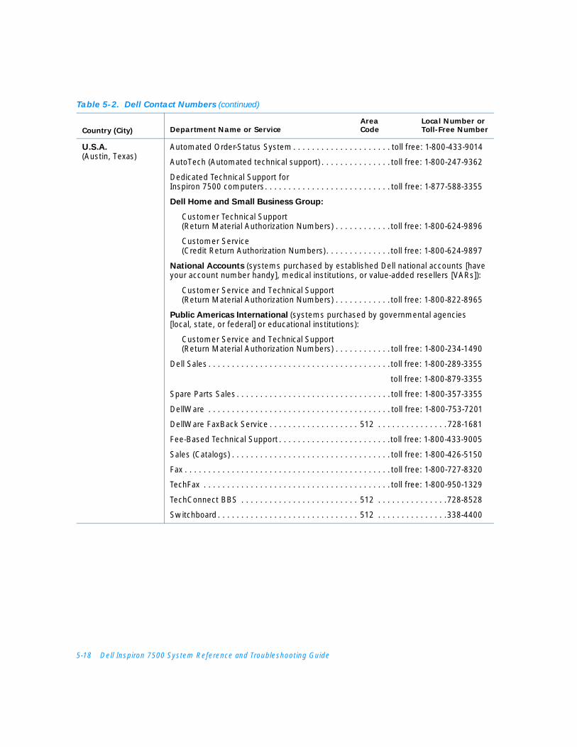
5-18 Dell Inspiron 7500 System Reference and Troubleshooting Guide
U.S.A.(Austin, Texas)
Automated Order-Status System . . . . . . . . . . . . . . . . . . . . . toll free: 1-800-433-9014
AutoTech (Automated technical support) . . . . . . . . . . . . . . . toll free: 1-800-247-9362
Dedicated Technical Support for Inspiron 7500 computers. . . . . . . . . . . . . . . . . . . . . . . . . . . toll free: 1-877-588-3355
Dell Home and Small Business Group:
Customer Technical Support(Return Material Authorization Numbers) . . . . . . . . . . . .toll free: 1-800-624-9896
Customer Service(Credit Return Authorization Numbers). . . . . . . . . . . . . .toll free: 1-800-624-9897
National Accounts (systems purchased by established Dell national accounts [have your account number handy], medical institutions, or value-added resellers [VARs]):
Customer Service and Technical Support(Return Material Authorization Numbers) . . . . . . . . . . . .toll free: 1-800-822-8965
Public Americas International (systems purchased by governmental agencies [local, state, or federal] or educational institutions):
Customer Service and Technical Support(Return Material Authorization Numbers) . . . . . . . . . . . . toll free: 1-800-234-1490
Dell Sales . . . . . . . . . . . . . . . . . . . . . . . . . . . . . . . . . . . . . . .toll free: 1-800-289-3355
toll free: 1-800-879-3355
Spare Parts Sales . . . . . . . . . . . . . . . . . . . . . . . . . . . . . . . . . toll free: 1-800-357-3355
DellWare . . . . . . . . . . . . . . . . . . . . . . . . . . . . . . . . . . . . . . . toll free: 1-800-753-7201
DellWare FaxBack Service . . . . . . . . . . . . . . . . . . . 512 . . . . . . . . . . . . . . .728-1681
Fee-Based Technical Support . . . . . . . . . . . . . . . . . . . . . . . .toll free: 1-800-433-9005
Sales (Catalogs) . . . . . . . . . . . . . . . . . . . . . . . . . . . . . . . . . . toll free: 1-800-426-5150
Fax . . . . . . . . . . . . . . . . . . . . . . . . . . . . . . . . . . . . . . . . . . . . toll free: 1-800-727-8320
TechFax . . . . . . . . . . . . . . . . . . . . . . . . . . . . . . . . . . . . . . . . toll free: 1-800-950-1329
TechConnect BBS . . . . . . . . . . . . . . . . . . . . . . . . . 512 . . . . . . . . . . . . . . .728-8528
Switchboard . . . . . . . . . . . . . . . . . . . . . . . . . . . . . . 512 . . . . . . . . . . . . . . .338-4400
Table 5-2. Dell Contact Numbers (continued)
Country (City)Area Local Number or
Department Name or Service Code Toll-Free Number
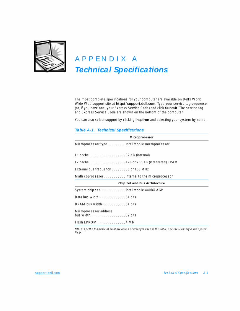
support.dell.com Technical Specifications A-1
A P P E N D I X A
Technical Specifications
The most complete specifications for your computer are available on Dell’s World Wide Web support site at http://support.dell.com. Type your service tag sequence (or, if you have one, your Express Service Code) and click Submit. The service tag and Express Service Code are shown on the bottom of the computer.
You can also select support by clicking Inspiron and selecting your system by name.
Table A-1. Technical Specifications
Microprocessor
Microprocessor type . . . . . . . . . Intel mobile microprocessor
L1 cache . . . . . . . . . . . . . . . . . . 32 KB (internal)
L2 cache . . . . . . . . . . . . . . . . . . 128 or 256 KB (integrated) SRAM
External bus frequency . . . . . . . 66 or 100 MHz
Math coprocessor . . . . . . . . . . . internal to the microprocessor
Chip Set and Bus Architecture
System chip set . . . . . . . . . . . . . Intel mobile 440BX AGP
Data bus width . . . . . . . . . . . . . 64 bits
DRAM bus width . . . . . . . . . . . . 64 bits
Microprocessor address bus width. . . . . . . . . . . . . . . . . . 32 bits
Flash EPROM . . . . . . . . . . . . . . 4 Mb
NOTE: For the full name of an abbreviation or acronym used in this table, see the Glossary in the system Help.
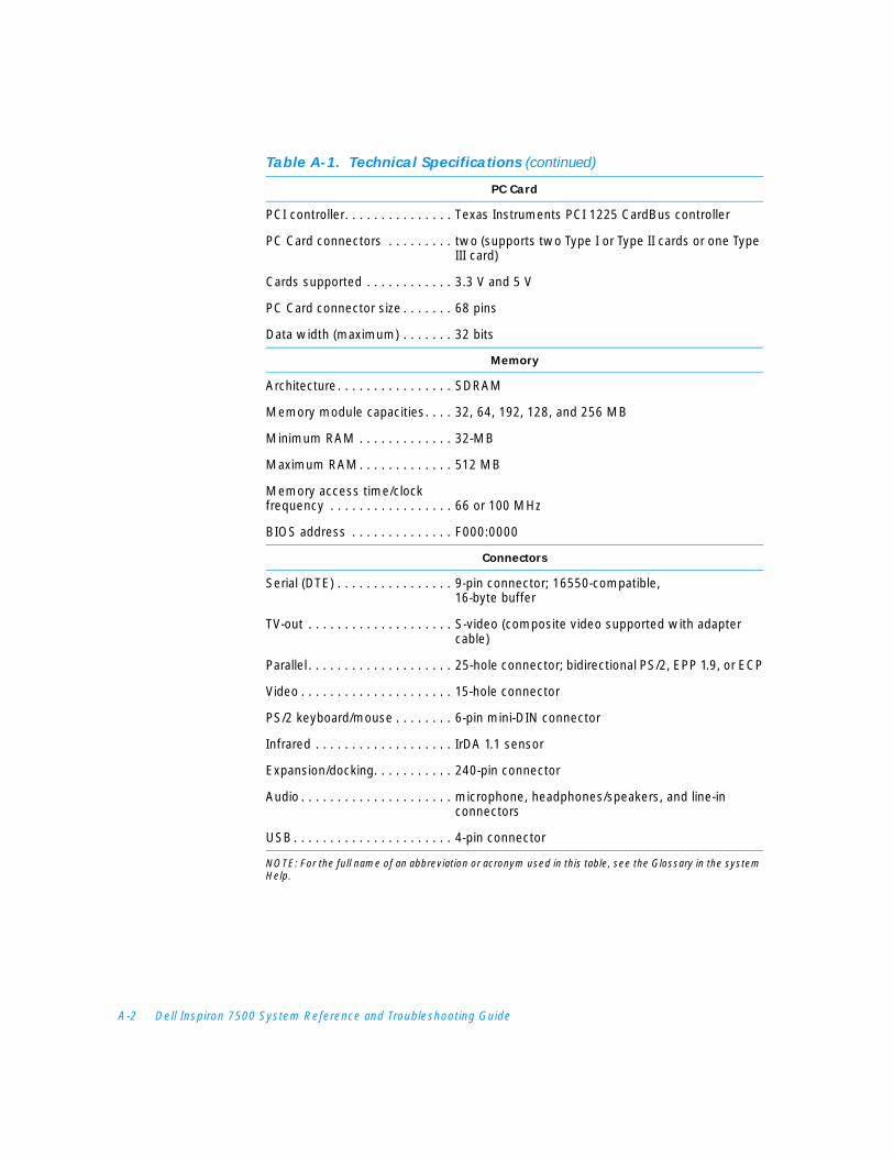
A-2 Dell Inspiron 7500 System Reference and Troubleshooting Guide
PC Card
PCI controller. . . . . . . . . . . . . . . Texas Instruments PCI 1225 CardBus controller
PC Card connectors . . . . . . . . . two (supports two Type I or Type II cards or one Type III card)
Cards supported . . . . . . . . . . . . 3.3 V and 5 V
PC Card connector size . . . . . . . 68 pins
Data width (maximum) . . . . . . . 32 bits
Memory
Architecture. . . . . . . . . . . . . . . . SDRAM
Memory module capacities. . . . 32, 64, 192, 128, and 256 MB
Minimum RAM . . . . . . . . . . . . . 32-MB
Maximum RAM. . . . . . . . . . . . . 512 MB
Memory access time/clock frequency . . . . . . . . . . . . . . . . . 66 or 100 MHz
BIOS address . . . . . . . . . . . . . . F000:0000
Connectors
Serial (DTE) . . . . . . . . . . . . . . . . 9-pin connector; 16550-compatible, 16-byte buffer
TV-out . . . . . . . . . . . . . . . . . . . . S-video (composite video supported with adapter cable)
Parallel. . . . . . . . . . . . . . . . . . . . 25-hole connector; bidirectional PS/2, EPP 1.9, or ECP
Video . . . . . . . . . . . . . . . . . . . . . 15-hole connector
PS/2 keyboard/mouse . . . . . . . . 6-pin mini-DIN connector
Infrared . . . . . . . . . . . . . . . . . . . IrDA 1.1 sensor
Expansion/docking. . . . . . . . . . . 240-pin connector
Audio . . . . . . . . . . . . . . . . . . . . . microphone, headphones/speakers, and line-in connectors
USB. . . . . . . . . . . . . . . . . . . . . . 4-pin connector
NOTE: For the full name of an abbreviation or acronym used in this table, see the Glossary in the system Help.
Table A-1. Technical Specifications (continued)
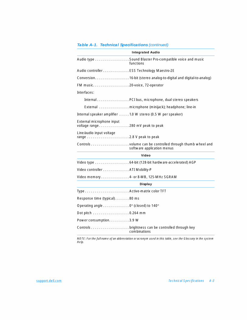
support.dell.com Technical Specifications A-3
Integrated Audio
Audio type . . . . . . . . . . . . . . . . . Sound Blaster Pro-compatible voice and music functions
Audio controller . . . . . . . . . . . . . ESS Technology Maestro-2E
Conversion. . . . . . . . . . . . . . . . . 16-bit (stereo analog-to-digital and digital-to-analog)
FM music. . . . . . . . . . . . . . . . . . 20-voice, 72-operator
Interfaces:
Internal . . . . . . . . . . . . . . . . PCI bus, microphone, dual stereo speakers
External . . . . . . . . . . . . . . . microphone (minijack); headphone; line-in
Internal speaker amplifier . . . . . 1.0 W stereo (0.5 W per speaker)
External microphone input voltage range . . . . . . . . . . . . . . . 280 mV peak to peak
Line/audio input voltage range . . . . . . . . . . . . . . . . . . . . . 2.8 V peak to peak
Controls . . . . . . . . . . . . . . . . . . . volume can be controlled through thumb wheel and software application menus
Video
Video type . . . . . . . . . . . . . . . . . 64-bit (128-bit hardware-accelerated) AGP
Video controller . . . . . . . . . . . . . ATI Mobility-P
Video memory . . . . . . . . . . . . . . 4- or 8-MB, 125-MHz SGRAM
Display
Type . . . . . . . . . . . . . . . . . . . . . . Active-matrix color TFT
Response time (typical) . . . . . . . 80 ms
Operating angle . . . . . . . . . . . . . 0° (closed) to 140°
Dot pitch . . . . . . . . . . . . . . . . . . 0.264 mm
Power consumption. . . . . . . . . . 3.9 W
Controls . . . . . . . . . . . . . . . . . . . brightness can be controlled through key combinations
NOTE: For the full name of an abbreviation or acronym used in this table, see the Glossary in the system Help.
Table A-1. Technical Specifications (continued)
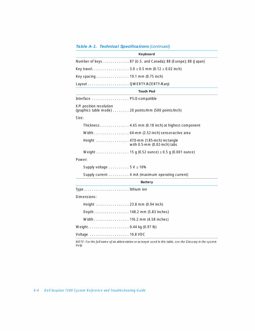
A-4 Dell Inspiron 7500 System Reference and Troubleshooting Guide
Keyboard
Number of keys. . . . . . . . . . . . . 87 (U.S. and Canada); 88 (Europe); 88 (Japan)
Key travel. . . . . . . . . . . . . . . . . . 3.0 ± 0.5 mm (0.12 ± 0.02 inch)
Key spacing . . . . . . . . . . . . . . . . 19.1 mm (0.75 inch)
Layout . . . . . . . . . . . . . . . . . . . . QWERTY/AZERTY/Kanji
Touch Pad
Interface . . . . . . . . . . . . . . . . . . PS/2-compatible
X/Y position resolution(graphics table mode) . . . . . . . . 20 points/mm (500 points/inch)
Size:
Thickness . . . . . . . . . . . . . . 4.65 mm (0.18 inch) at highest component
Width . . . . . . . . . . . . . . . . . 64-mm (2.52-inch) sensor-active area
Height . . . . . . . . . . . . . . . . 47.0-mm (1.85-inch) rectangle with 0.5-mm (0.02-inch) tabs
Weight . . . . . . . . . . . . . . . . 15 g (0.52 ounce) ± 0.5 g (0.001 ounce)
Power:
Supply voltage . . . . . . . . . . 5 V ± 10%
Supply current . . . . . . . . . . 4 mA (maximum operating current)
Battery
Type. . . . . . . . . . . . . . . . . . . . . . lithium ion
Dimensions:
Height . . . . . . . . . . . . . . . . 23.8 mm (0.94 inch)
Depth . . . . . . . . . . . . . . . . . 148.2 mm (5.83 inches)
Width . . . . . . . . . . . . . . . . . 116.2 mm (4.58 inches)
Weight. . . . . . . . . . . . . . . . . . . . 0.44 kg (0.97 lb)
Voltage . . . . . . . . . . . . . . . . . . . 10.8 VDC
NOTE: For the full name of an abbreviation or acronym used in this table, see the Glossary in the system Help.
Table A-1. Technical Specifications (continued)
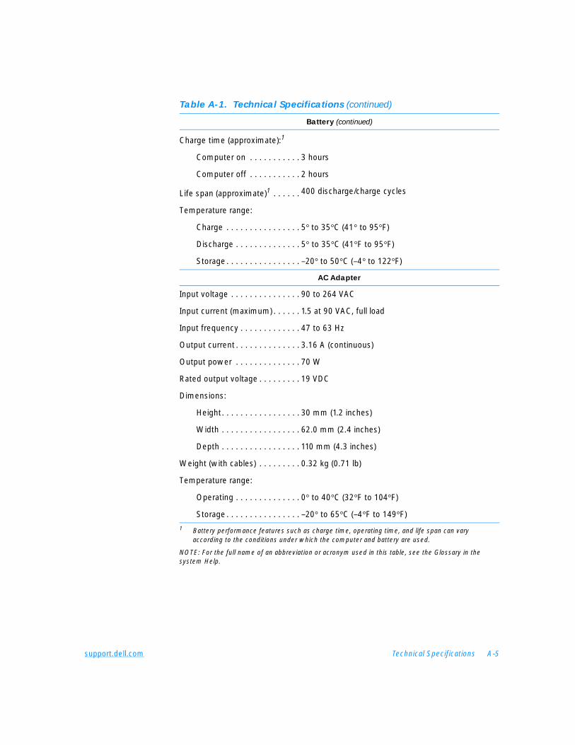
support.dell.com Technical Specifications A-5
Battery (continued)
Charge time (approximate):1
Computer on . . . . . . . . . . . 3 hours
Computer off . . . . . . . . . . . 2 hours
Life span (approximate)1 . . . . . . 400 discharge/charge cycles
Temperature range:
Charge . . . . . . . . . . . . . . . . 5° to 35°C (41° to 95°F)
Discharge . . . . . . . . . . . . . . 5° to 35°C (41°F to 95°F)
Storage. . . . . . . . . . . . . . . . –20° to 50°C (–4° to 122°F)
AC Adapter
Input voltage . . . . . . . . . . . . . . . 90 to 264 VAC
Input current (maximum) . . . . . . 1.5 at 90 VAC, full load
Input frequency . . . . . . . . . . . . . 47 to 63 Hz
Output current . . . . . . . . . . . . . . 3.16 A (continuous)
Output power . . . . . . . . . . . . . . 70 W
Rated output voltage . . . . . . . . . 19 VDC
Dimensions:
Height. . . . . . . . . . . . . . . . . 30 mm (1.2 inches)
Width . . . . . . . . . . . . . . . . . 62.0 mm (2.4 inches)
Depth . . . . . . . . . . . . . . . . . 110 mm (4.3 inches)
Weight (with cables) . . . . . . . . . 0.32 kg (0.71 lb)
Temperature range:
Operating . . . . . . . . . . . . . . 0° to 40°C (32°F to 104°F)
Storage. . . . . . . . . . . . . . . . –20° to 65°C (–4°F to 149°F)
1 Battery performance features such as charge time, operating time, and life span can vary according to the conditions under which the computer and battery are used.
NOTE: For the full name of an abbreviation or acronym used in this table, see the Glossary in the system Help.
Table A-1. Technical Specifications (continued)
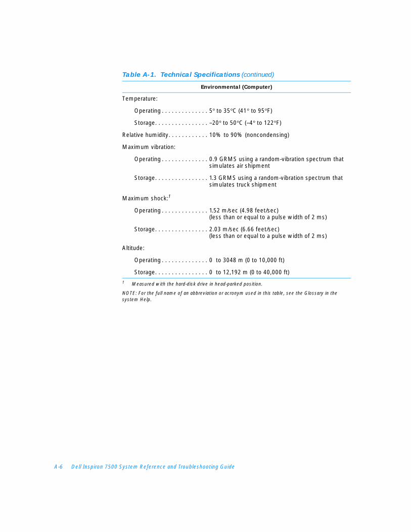
A-6 Dell Inspiron 7500 System Reference and Troubleshooting Guide
Environmental (Computer)
Temperature:
Operating . . . . . . . . . . . . . . 5° to 35°C (41° to 95°F)
Storage. . . . . . . . . . . . . . . . –20° to 50°C (–4° to 122°F)
Relative humidity. . . . . . . . . . . . 10% to 90% (noncondensing)
Maximum vibration:
Operating . . . . . . . . . . . . . . 0.9 GRMS using a random-vibration spectrum that simulates air shipment
Storage. . . . . . . . . . . . . . . . 1.3 GRMS using a random-vibration spectrum that simulates truck shipment
Maximum shock:1
Operating . . . . . . . . . . . . . . 1.52 m/sec (4.98 feet/sec) (less than or equal to a pulse width of 2 ms)
Storage. . . . . . . . . . . . . . . . 2.03 m/sec (6.66 feet/sec)(less than or equal to a pulse width of 2 ms)
Altitude:
Operating . . . . . . . . . . . . . . 0 to 3048 m (0 to 10,000 ft)
Storage. . . . . . . . . . . . . . . . 0 to 12,192 m (0 to 40,000 ft)
1 Measured with the hard-disk drive in head-parked position.
NOTE: For the full name of an abbreviation or acronym used in this table, see the Glossary in the system Help.
Table A-1. Technical Specifications (continued)
support.dell.com Using the Setup Program B-1
A P P E N D I X B
Using the Setup Program
This appendix describes the Setup program, which you can use to configure your computer system as well as enable and disable your system’s password features.
Your computer retains system configuration information in the nonvolatile random-access memory (NVRAM) maintained by your computer’s reserve battery. Each time you turn on your computer, the system compares the installed hardware with the system configuration information stored in NVRAM. If the system detects a discrepancy, it generates an error message that identifies the incorrect configuration setting.
You can use the Setup program as follows:
• To change your system configuration information after you add, change, or remove hardware connected to or installed inside your computer
• To verify information about your computer’s current configuration, such as the amount of system memory
• To set or change user-selectable features — for example, power management or security features
NOTE: Many of the options that are configured in the Setup program are overridden by the settings in the Windows control panels, such as the Power
Management control panel. When your computer is running the Windows 98 operating system, it will use the settings that are selected in the Windows control panels rather than those set in the Setup program.
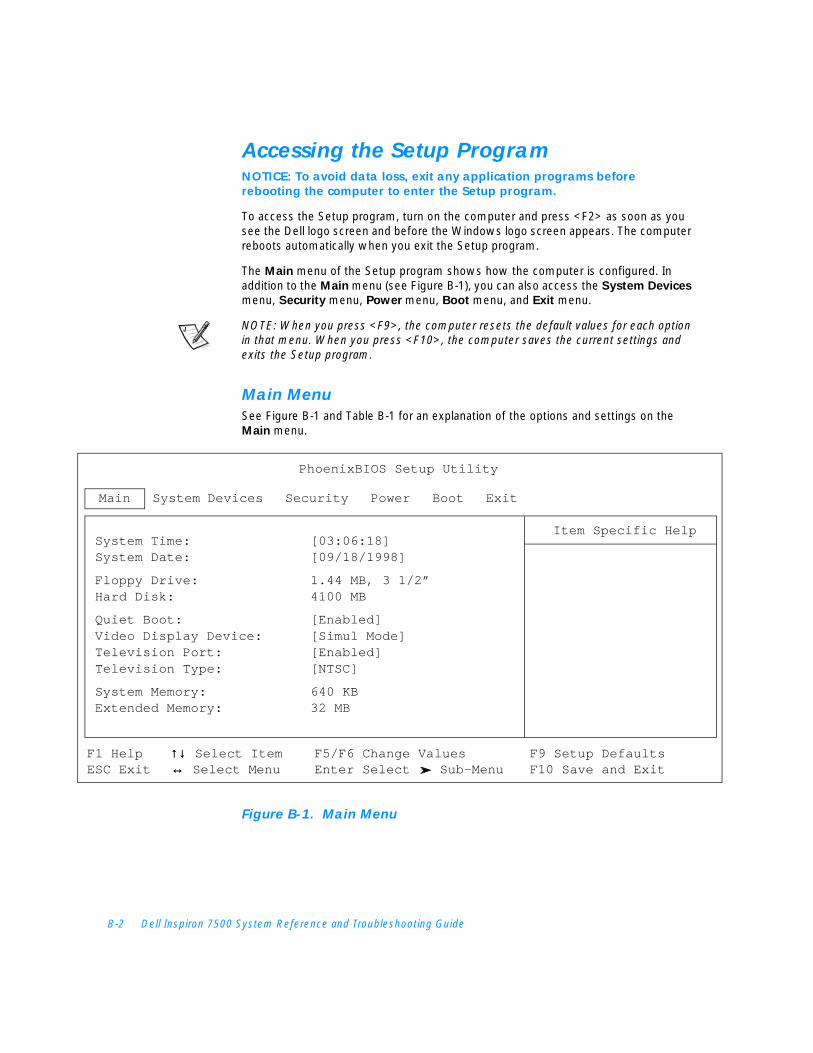
B-2 Dell Inspiron 7500 System Reference and Troubleshooting Guide
Accessing the Setup Program NOTICE: To avoid data loss, exit any application programs before rebooting the computer to enter the Setup program.
To access the Setup program, turn on the computer and press <F2> as soon as you see the Dell logo screen and before the Windows logo screen appears. The computer reboots automatically when you exit the Setup program.
The Main menu of the Setup program shows how the computer is configured. In addition to the Main menu (see Figure B-1), you can also access the System Devices menu, Security menu, Power menu, Boot menu, and Exit menu.
NOTE: When you press <F9>, the computer resets the default values for each option in that menu. When you press <F10>, the computer saves the current settings and exits the Setup program.
Main MenuSee Figure B-1 and Table B-1 for an explanation of the options and settings on the Main menu.
Figure B-1. Main Menu
Main System Devices Security Power Boot Exit
System Time: [03:06:18]System Date: [09/18/1998]
Floppy Drive: 1.44 MB, 3 1/2”Hard Disk: 4100 MB
Quiet Boot: [Enabled]Video Display Device: [Simul Mode]Television Port: [Enabled]Television Type: [NTSC]
System Memory: 640 KBExtended Memory: 32 MB
PhoenixBIOS Setup Utility
Item Specific Help
F1 Help ↑↓↑↓ Select Item F5/F6 Change Values F9 Setup DefaultsESC Exit ↔↔ Select Menu Enter Select Sub-Menu F10 Save and Exit
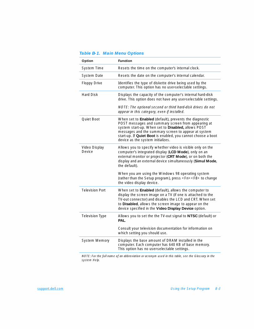
support.dell.com Using the Setup Program B-3
Table B-1. Main Menu Options
Option Function
System Time Resets the time on the computer’s internal clock.
System Date Resets the date on the computer’s internal calendar.
Floppy Drive Identifies the type of diskette drive being used by the computer. This option has no user-selectable settings.
Hard Disk Displays the capacity of the computer's internal hard-disk drive. This option does not have any user-selectable settings.
NOTE: The optional second or third hard-disk drives do not appear in this category, even if installed.
Quiet Boot When set to Enabled (default), prevents the diagnostic POST messages and summary screen from appearing at system start-up. When set to Disabled, allows POST messages and the summary screen to appear at system start-up. If Quiet Boot is enabled, you cannot choose a boot device as the system initializes.
Video Display Device
Allows you to specify whether video is visible only on the computer’s integrated display (LCD Mode), only on an external monitor or projector (CRT Mode), or on both the display and an external device simultaneously (Simul Mode, the default).
When you are using the Windows 98 operating system (rather than the Setup program), press <Fn><F8> to change the video display device.
Television Port When set to Enabled (default), allows the computer to display the screen image on a TV (if one is attached to the TV-out connector) and disables the LCD and CRT. When set to Disabled, allows the screen image to appear on the device specified in the Video Display Device option.
Television Type Allows you to set the the TV-out signal to NTSC (default) or PAL.
Consult your television documentation for information on which setting you should use.
System Memory Displays the base amount of DRAM installed in the computer. Each computer has 640 KB of base memory. This option has no user-selectable settings.
NOTE: For the full name of an abbreviation or acronym used in this table, see the Glossary in the system Help.
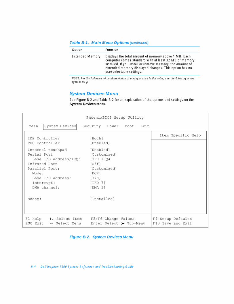
B-4 Dell Inspiron 7500 System Reference and Troubleshooting Guide
System Devices MenuSee Figure B-2 and Table B-2 for an explanation of the options and settings on the System Devices menu.
Figure B-2. System Devices Menu
Extended Memory Displays the total amount of memory above 1 MB. Each computer comes standard with at least 32 MB of memory installed. If you install or remove memory, the amount of extended memory displayed changes. This option has no user-selectable settings.
Table B-1. Main Menu Options (continued)
Option Function
NOTE: For the full name of an abbreviation or acronym used in this table, see the Glossary in the system Help.
Main System Devices Security Power Boot Exit
IDE Controller [Both]FDD Controller [Enabled]
Internal touchpad [Enabled]Serial Port [Customized]
Base I/O address/IRQ: [3F8 IRQ4Infrared Port [Off]Parallel Port: [Customized]
Mode: [ECP]Base I/O address: [378]Interrupt: [IRQ 7]DMA channel: [DMA 3]
Modem: [Installed]
PhoenixBIOS Setup Utility
Item Specific Help
F1 Help ↑↓↑↓ Select Item F5/F6 Change Values F9 Setup DefaultsESC Exit ↔↔ Select Menu Enter Select Sub-Menu F10 Save and Exit
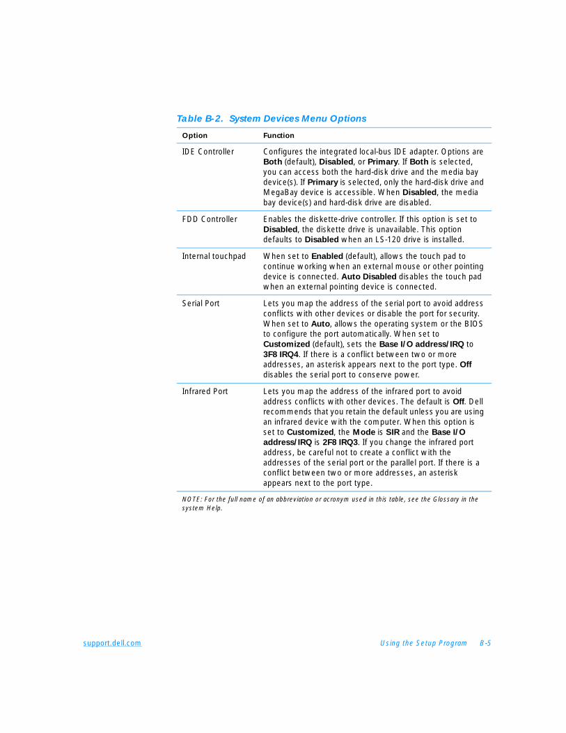
support.dell.com Using the Setup Program B-5
Table B-2. System Devices Menu Options
Option Function
IDE Controller Configures the integrated local-bus IDE adapter. Options are Both (default), Disabled, or Primary. If Both is selected, you can access both the hard-disk drive and the media bay device(s). If Primary is selected, only the hard-disk drive and MegaBay device is accessible. When Disabled, the media bay device(s) and hard-disk drive are disabled.
FDD Controller Enables the diskette-drive controller. If this option is set to Disabled, the diskette drive is unavailable. This option defaults to Disabled when an LS-120 drive is installed.
Internal touchpad When set to Enabled (default), allows the touch pad to continue working when an external mouse or other pointing device is connected. Auto Disabled disables the touch pad when an external pointing device is connected.
Serial Port Lets you map the address of the serial port to avoid address conflicts with other devices or disable the port for security. When set to Auto, allows the operating system or the BIOS to configure the port automatically. When set to Customized (default), sets the Base I/O address/IRQ to 3F8 IRQ4. If there is a conflict between two or more addresses, an asterisk appears next to the port type. Off disables the serial port to conserve power.
Infrared Port Lets you map the address of the infrared port to avoid address conflicts with other devices. The default is Off. Dell recommends that you retain the default unless you are using an infrared device with the computer. When this option is set to Customized, the Mode is SIR and the Base I/O
address/IRQ is 2F8 IRQ3. If you change the infrared port address, be careful not to create a conflict with the addresses of the serial port or the parallel port. If there is a conflict between two or more addresses, an asterisk appears next to the port type.
NOTE: For the full name of an abbreviation or acronym used in this table, see the Glossary in the system Help.
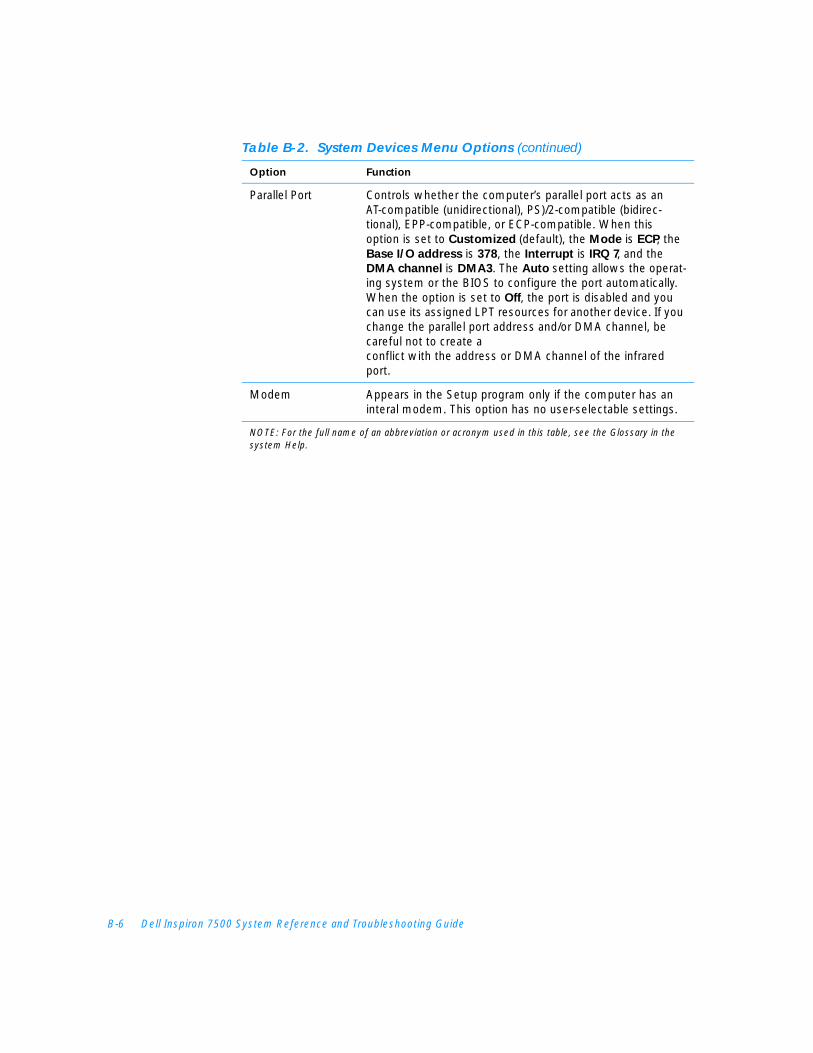
B-6 Dell Inspiron 7500 System Reference and Troubleshooting Guide
Parallel Port Controls whether the computer’s parallel port acts as an AT-compatible (unidirectional), PS)/2-compatible (bidirec-tional), EPP-compatible, or ECP-compatible. When this option is set to Customized (default), the Mode is ECP, the Base I/O address is 378, the Interrupt is IRQ 7, and the DMA channel is DMA3. The Auto setting allows the operat-ing system or the BIOS to configure the port automatically. When the option is set to Off, the port is disabled and you can use its assigned LPT resources for another device. If you change the parallel port address and/or DMA channel, be careful not to create a conflict with the address or DMA channel of the infrared port.
Modem Appears in the Setup program only if the computer has an interal modem. This option has no user-selectable settings.
Table B-2. System Devices Menu Options (continued)
Option Function
NOTE: For the full name of an abbreviation or acronym used in this table, see the Glossary in the system Help.
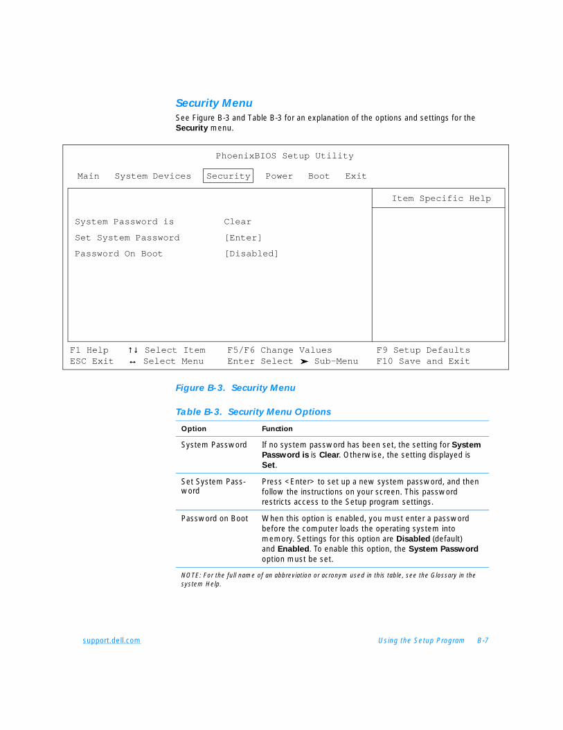
support.dell.com Using the Setup Program B-7
Security MenuSee Figure B-3 and Table B-3 for an explanation of the options and settings for the Security menu.
Figure B-3. Security Menu
Main System Devices Security Power Boot Exit
System Password is Clear
Set System Password [Enter]
Password On Boot [Disabled]
PhoenixBIOS Setup Utility
Item Specific Help
F1 Help ↑↓↑↓ Select Item F5/F6 Change Values F9 Setup DefaultsESC Exit ↔↔ Select Menu Enter Select Sub-Menu F10 Save and Exit
Table B-3. Security Menu Options
Option Function
System Password If no system password has been set, the setting for System
Password is is Clear. Otherwise, the setting displayed is Set.
Set System Pass-word
Press <Enter> to set up a new system password, and then follow the instructions on your screen. This password restricts access to the Setup program settings.
Password on Boot When this option is enabled, you must enter a password before the computer loads the operating system into memory. Settings for this option are Disabled (default) and Enabled. To enable this option, the System Password
option must be set.
NOTE: For the full name of an abbreviation or acronym used in this table, see the Glossary in the system Help.
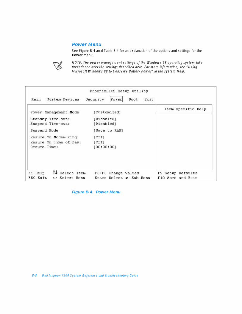
B-8 Dell Inspiron 7500 System Reference and Troubleshooting Guide
Power MenuSee Figure B-4 an d Table B-4 for an explanation of the options and settings for the Power menu.
NOTE: The power management settings of the Windows 98 operating system take precedence over the settings described here. For more information, see “Using Microsoft Windows 98 to Conserve Battery Power” in the system Help.
Figure B-4. Power Menu
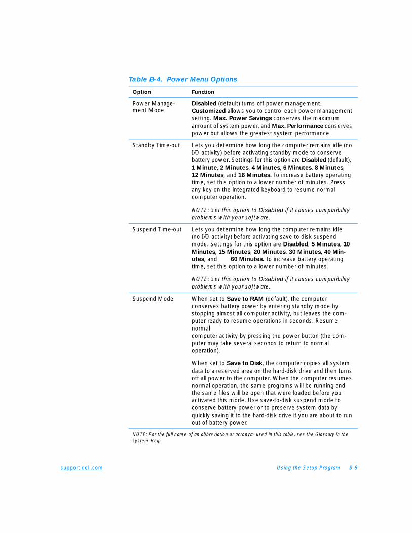
support.dell.com Using the Setup Program B-9
Table B-4. Power Menu Options
Option Function
Power Manage-ment Mode
Disabled (default) turns off power management. Customized allows you to control each power management setting. Max. Power Savings conserves the maximum amount of system power, and Max. Performance conserves power but allows the greatest system performance.
Standby Time-out Lets you determine how long the computer remains idle (no I/O activity) before activating standby mode to conserve battery power. Settings for this option are Disabled (default), 1 Minute, 2 Minutes, 4 Minutes, 6 Minutes, 8 Minutes, 12 Minutes, and 16 Minutes. To increase battery operating time, set this option to a lower number of minutes. Press any key on the integrated keyboard to resume normal computer operation.
NOTE: Set this option to Disabled if it causes compatibility problems with your software.
Suspend Time-out Lets you determine how long the computer remains idle (no I/O activity) before activating save-to-disk suspend mode. Settings for this option are Disabled, 5 Minutes, 10
Minutes, 15 Minutes, 20 Minutes, 30 Minutes, 40 Min-
utes, and 60 Minutes. To increase battery operating time, set this option to a lower number of minutes.
NOTE: Set this option to Disabled if it causes compatibility problems with your software.
Suspend Mode When set to Save to RAM (default), the computer conserves battery power by entering standby mode by stopping almost all computer activity, but leaves the com-puter ready to resume operations in seconds. Resume normal computer activity by pressing the power button (the com-puter may take several seconds to return to normal operation).
When set to Save to Disk, the computer copies all system data to a reserved area on the hard-disk drive and then turns off all power to the computer. When the computer resumes normal operation, the same programs will be running and the same files will be open that were loaded before you activated this mode. Use save-to-disk suspend mode to conserve battery power or to preserve system data by quickly saving it to the hard-disk drive if you are about to run out of battery power.
NOTE: For the full name of an abbreviation or acronym used in this table, see the Glossary in the system Help.
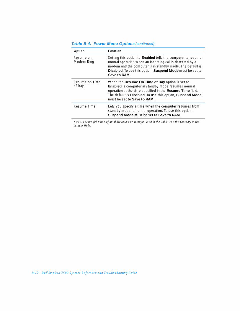
B-10 Dell Inspiron 7500 System Reference and Troubleshooting Guide
Resume on Modem Ring
Setting this option to Enabled tells the computer to resume normal operation when an incoming call is detected by a modem and the computer is in standby mode. The default is Disabled. To use this option, Suspend Mode must be set to Save to RAM.
Resume on Time of Day
When the Resume On Time of Day option is set to Enabled, a computer in standby mode resumes normal operation at the time specified in the Resume Time field. The default is Disabled. To use this option, Suspend Mode must be set to Save to RAM.
Resume Time Lets you specify a time when the computer resumes from standby mode to normal operation. To use this option, Suspend Mode must be set to Save to RAM.
Table B-4. Power Menu Options (continued)
Option Function
NOTE: For the full name of an abbreviation or acronym used in this table, see the Glossary in the system Help.
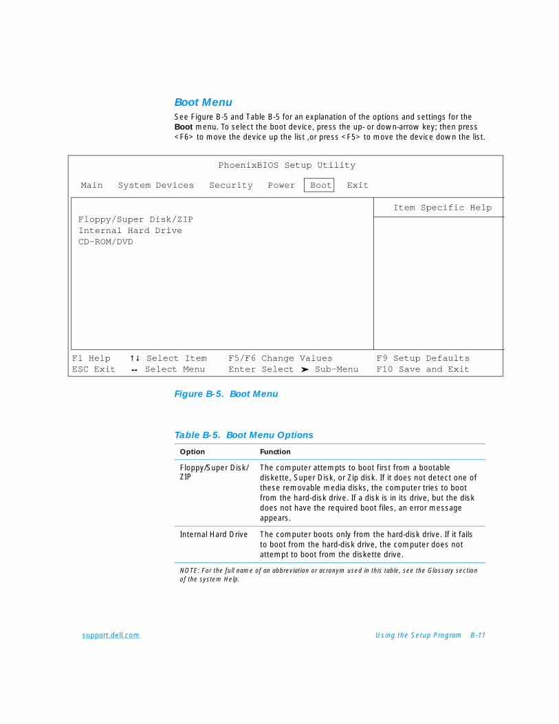
support.dell.com Using the Setup Program B-11
Boot Menu See Figure B-5 and Table B-5 for an explanation of the options and settings for the Boot menu. To select the boot device, press the up- or down-arrow key; then press <F6> to move the device up the list ,or press <F5> to move the device down the list.
Figure B-5. Boot Menu
Main System Devices Security Power Boot Exit
Floppy/Super Disk/ZIPInternal Hard DriveCD-ROM/DVD
PhoenixBIOS Setup Utility
Item Specific Help
F1 Help ↑↓↑↓ Select Item F5/F6 Change Values F9 Setup DefaultsESC Exit ↔↔ Select Menu Enter Select Sub-Menu F10 Save and Exit
Table B-5. Boot Menu Options
Option Function
Floppy/Super Disk/ZIP
The computer attempts to boot first from a bootable diskette, Super Disk, or Zip disk. If it does not detect one of these removable media disks, the computer tries to boot from the hard-disk drive. If a disk is in its drive, but the disk does not have the required boot files, an error message appears.
Internal Hard Drive The computer boots only from the hard-disk drive. If it fails to boot from the hard-disk drive, the computer does not attempt to boot from the diskette drive.
NOTE: For the full name of an abbreviation or acronym used in this table, see the Glossary section of the system Help.
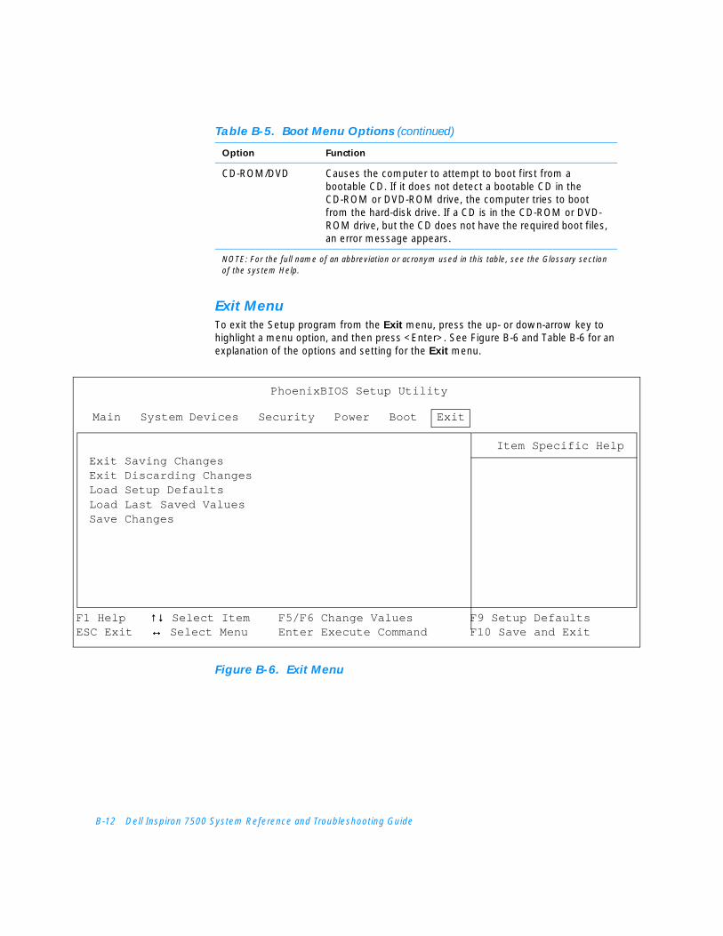
B-12 Dell Inspiron 7500 System Reference and Troubleshooting Guide
Exit MenuTo exit the Setup program from the Exit menu, press the up- or down-arrow key to highlight a menu option, and then press <Enter>. See Figure B-6 and Table B-6 for an explanation of the options and setting for the Exit menu.
Figure B-6. Exit Menu
CD-ROM/DVD Causes the computer to attempt to boot first from a bootable CD. If it does not detect a bootable CD in the CD-ROM or DVD-ROM drive, the computer tries to boot from the hard-disk drive. If a CD is in the CD-ROM or DVD-ROM drive, but the CD does not have the required boot files, an error message appears.
Table B-5. Boot Menu Options (continued)
Option Function
NOTE: For the full name of an abbreviation or acronym used in this table, see the Glossary section of the system Help.
Main System Devices Security Power Boot Exit
Exit Saving ChangesExit Discarding ChangesLoad Setup DefaultsLoad Last Saved ValuesSave Changes
PhoenixBIOS Setup Utility
Item Specific Help
F1 Help ↑↓↑↓ Select Item F5/F6 Change Values F9 Setup DefaultsESC Exit ↔↔ Select Menu Enter Execute Command F10 Save and Exit

support.dell.com Using the Setup Program B-13
Table B-6. Exit Menu Options
Option Function
Exit Saving Changes
Saves any changes you have made and exits the Setup program
Exit Discarding Changes
Discards any changes you have made and exits the Setup program.
Load Setup Defaults
Discards any changes you have made and reverts all options to their original default settings, but does not exit the Setup program.
Load Last Saved Values
Discards the settings you have made and restores the settings you previously saved. Press <Enter> when prompted to continue.
Save Changes Saves settings without exiting the Setup program. Press <Enter> when prompted to continue, and then return to other menus to make changes.
NOTE: For the full name of an abbreviation or acronym used in this table, see the Glossary section of the system Help.

B-14 Dell Inspiron 7500 System Reference and Troubleshooting Guide
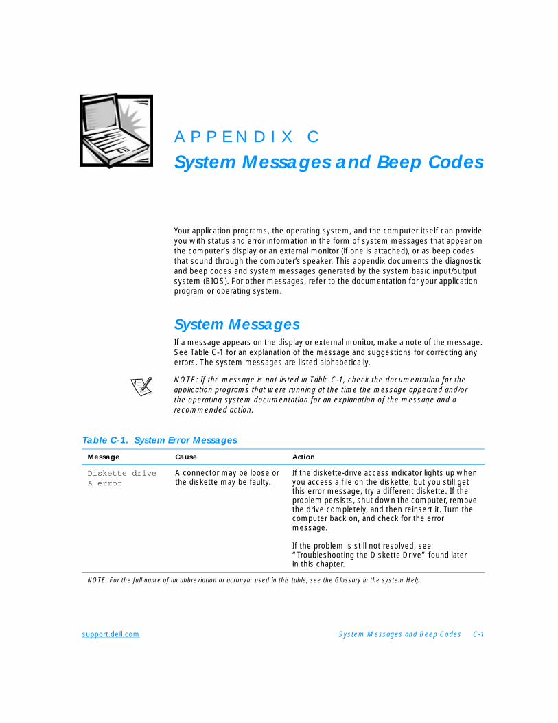
support.dell.com System Messages and Beep Codes C-1
A P P E N D I X C
System Messages and Beep Codes
Your application programs, the operating system, and the computer itself can provide you with status and error information in the form of system messages that appear on the computer’s display or an external monitor (if one is attached), or as beep codes that sound through the computer’s speaker. This appendix documents the diagnostic and beep codes and system messages generated by the system basic input/output system (BIOS). For other messages, refer to the documentation for your application program or operating system.
System MessagesIf a message appears on the display or external monitor, make a note of the message. See Table C-1 for an explanation of the message and suggestions for correcting any errors. The system messages are listed alphabetically.
NOTE: If the message is not listed in Table C-1, check the documentation for the application programs that were running at the time the message appeared and/or the operating system documentation for an explanation of the message and a recommended action.
Table C-1. System Error Messages
Message Cause Action
Diskette drive A error
A connector may be loose or the diskette may be faulty.
If the diskette-drive access indicator lights up when you access a file on the diskette, but you still get this error message, try a different diskette. If the problem persists, shut down the computer, remove the drive completely, and then reinsert it. Turn the computer back on, and check for the error message.
If the problem is still not resolved, see “Troubleshooting the Diskette Drive” found later in this chapter.
NOTE: For the full name of an abbreviation or acronym used in this table, see the Glossary in the system Help.
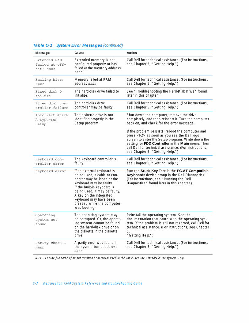
C-2 Dell Inspiron 7500 System Reference and Troubleshooting Guide
Extended RAM failed at off-set: nnnn
Extended memory is not configured properly or has failed at the memory address nnnn.
Call Dell for technical assistance. (For instructions, see Chapter 5, “Getting Help.”)
Failing bits: nnnn
Memory failed at RAM address nnnn.
Call Dell for technical assistance. (For instructions, see Chapter 5, “Getting Help.”)
Fixed disk 0 failure
The hard-disk drive failed to initialize.
See “Troubleshooting the Hard-Disk Drive” found later in this chapter.
Fixed disk con-troller failure
The hard-disk drive controller may be faulty.
Call Dell for technical assistance. (For instructions, see Chapter 5, “Getting Help.”)
Incorrect drive A type—run Setup
The diskette drive is not identified properly in the Setup program.
Shut down the computer, remove the drive completely, and then reinsert it. Turn the computer back on, and check for the error message.
If the problem persists, reboot the computer and press <F2> as soon as you see the Dell logo screen to enter the Setup program. Write down the setting for FDD Controller in the Main menu. Then call Dell for technical assistance. (For instructions, see Chapter 5, “Getting Help.”)
Keyboard con-troller error
The keyboard controller is faulty.
Call Dell for technical assistance. (For instructions, see Chapter 5, “Getting Help.”)
Keyboard error If an external keyboard is being used, a cable or con-nector may be loose or the keyboard may be faulty.If the built-in keyboard is being used, it may be faulty. A key on the integrated keyboard may have been pressed while the computer was booting.
Run the Stuck Key Test in the PC-AT Compatible Keyboards device group in the Dell Diagnostics. (For instructions, see “Running the Dell Diagnostics” found later in this chapter.)
Operating system not found
The operating system may be corrupted. Or, the operat-ing system cannot be found on the hard-disk drive or on the diskette in the diskette drive.
Reinstall the operating system. See the documentation that came with the operating sys-tem. If the problem is still not resolved, call Dell for technical assistance. (For instructions, see Chapter 5, “Getting Help.”)
Parity check 1 nnnn
A parity error was found in the system bus at address nnnn.
Call Dell for technical assistance. (For instructions, see Chapter 5, “Getting Help.”)
Table C-1. System Error Messages (continued)
Message Cause Action
NOTE: For the full name of an abbreviation or acronym used in this table, see the Glossary in the system Help.
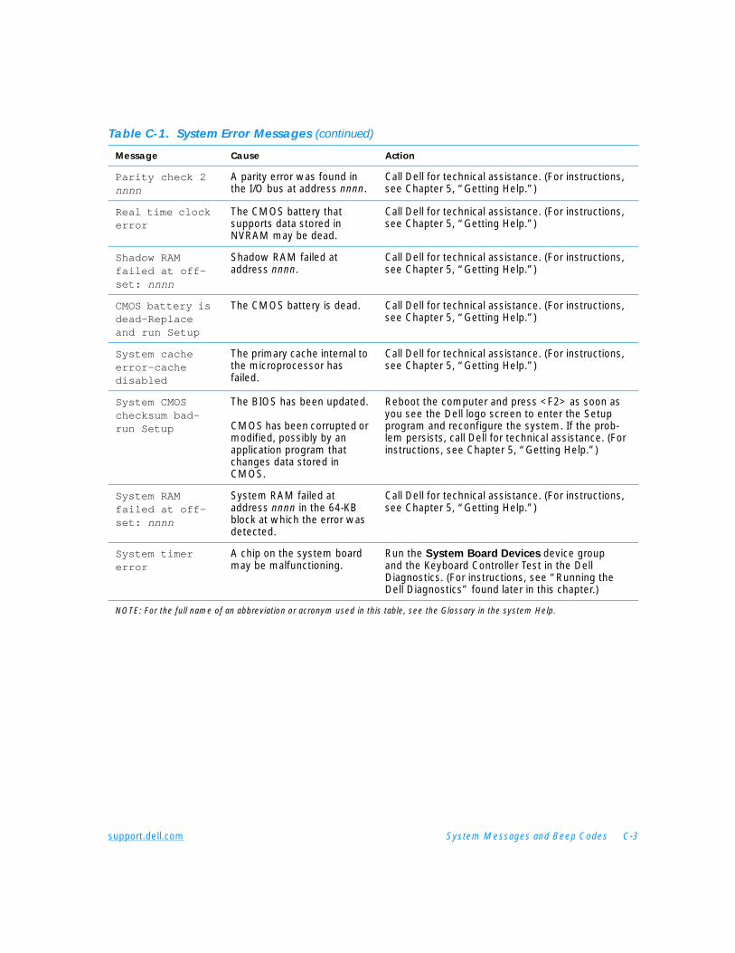
support.dell.com System Messages and Beep Codes C-3
Parity check 2 nnnn
A parity error was found in the I/O bus at address nnnn.
Call Dell for technical assistance. (For instructions, see Chapter 5, “Getting Help.”)
Real time clock error
The CMOS battery that supports data stored in NVRAM may be dead.
Call Dell for technical assistance. (For instructions, see Chapter 5, “Getting Help.”)
Shadow RAM failed at off-set: nnnn
Shadow RAM failed at address nnnn.
Call Dell for technical assistance. (For instructions, see Chapter 5, “Getting Help.”)
CMOS battery is dead—Replace and run Setup
The CMOS battery is dead. Call Dell for technical assistance. (For instructions, see Chapter 5, “Getting Help.”)
System cache error—cache disabled
The primary cache internal to the microprocessor has failed.
Call Dell for technical assistance. (For instructions, see Chapter 5, “Getting Help.”)
System CMOS checksum bad—run Setup
The BIOS has been updated.
CMOS has been corrupted or modified, possibly by an application program that changes data stored in CMOS.
Reboot the computer and press <F2> as soon as you see the Dell logo screen to enter the Setup program and reconfigure the system. If the prob-lem persists, call Dell for technical assistance. (For instructions, see Chapter 5, “Getting Help.”)
System RAM failed at off-set: nnnn
System RAM failed at address nnnn in the 64-KB block at which the error was detected.
Call Dell for technical assistance. (For instructions, see Chapter 5, “Getting Help.”)
System timer error
A chip on the system board may be malfunctioning.
Run the System Board Devices device group and the Keyboard Controller Test in the Dell Diagnostics. (For instructions, see “Running the Dell Diagnostics” found later in this chapter.)
Table C-1. System Error Messages (continued)
Message Cause Action
NOTE: For the full name of an abbreviation or acronym used in this table, see the Glossary in the system Help.
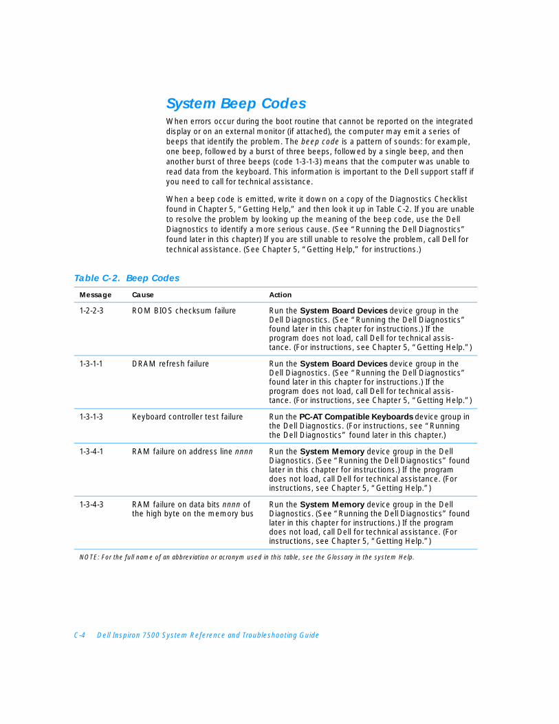
C-4 Dell Inspiron 7500 System Reference and Troubleshooting Guide
System Beep CodesWhen errors occur during the boot routine that cannot be reported on the integrated display or on an external monitor (if attached), the computer may emit a series of beeps that identify the problem. The beep code is a pattern of sounds: for example, one beep, followed by a burst of three beeps, followed by a single beep, and then another burst of three beeps (code 1-3-1-3) means that the computer was unable to read data from the keyboard. This information is important to the Dell support staff if you need to call for technical assistance.
When a beep code is emitted, write it down on a copy of the Diagnostics Checklist found in Chapter 5, “Getting Help,” and then look it up in Table C-2. If you are unable to resolve the problem by looking up the meaning of the beep code, use the Dell Diagnostics to identify a more serious cause. (See “Running the Dell Diagnostics” found later in this chapter) If you are still unable to resolve the problem, call Dell for technical assistance. (See Chapter 5, “Getting Help,” for instructions.)
.
Table C-2. Beep Codes
Message Cause Action
1-2-2-3 ROM BIOS checksum failure Run the System Board Devices device group in the Dell Diagnostics. (See “Running the Dell Diagnostics” found later in this chapter for instructions.) If the program does not load, call Dell for technical assis-tance. (For instructions, see Chapter 5, “Getting Help.”)
1-3-1-1 DRAM refresh failure Run the System Board Devices device group in the Dell Diagnostics. (See “Running the Dell Diagnostics” found later in this chapter for instructions.) If the program does not load, call Dell for technical assis-tance. (For instructions, see Chapter 5, “Getting Help.”)
1-3-1-3 Keyboard controller test failure Run the PC-AT Compatible Keyboards device group in the Dell Diagnostics. (For instructions, see “Running the Dell Diagnostics” found later in this chapter.)
1-3-4-1 RAM failure on address line nnnn Run the System Memory device group in the Dell Diagnostics. (See “Running the Dell Diagnostics” found later in this chapter for instructions.) If the program does not load, call Dell for technical assistance. (For instructions, see Chapter 5, “Getting Help.”)
1-3-4-3 RAM failure on data bits nnnn of the high byte on the memory bus
Run the System Memory device group in the Dell Diagnostics. (See “Running the Dell Diagnostics” found later in this chapter for instructions.) If the program does not load, call Dell for technical assistance. (For instructions, see Chapter 5, “Getting Help.”)
NOTE: For the full name of an abbreviation or acronym used in this table, see the Glossary in the system Help.
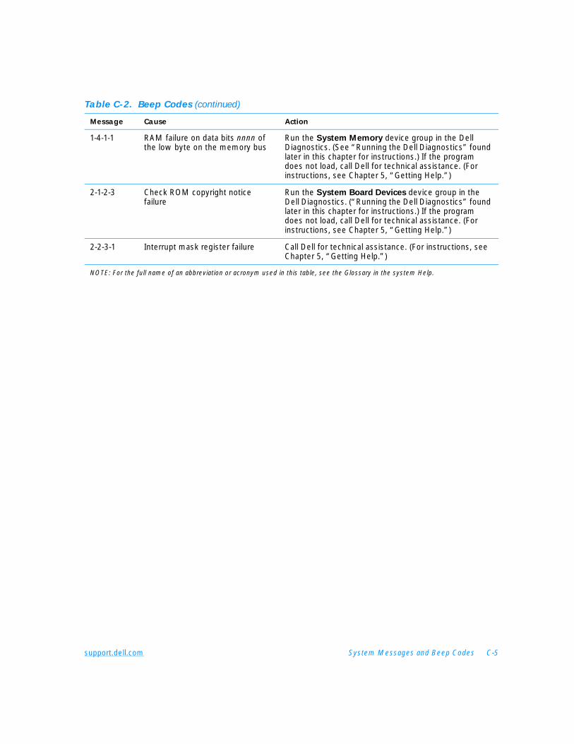
support.dell.com System Messages and Beep Codes C-5
1-4-1-1 RAM failure on data bits nnnn of the low byte on the memory bus
Run the System Memory device group in the Dell Diagnostics. (See “Running the Dell Diagnostics” found later in this chapter for instructions.) If the program does not load, call Dell for technical assistance. (For instructions, see Chapter 5, “Getting Help.”)
2-1-2-3 Check ROM copyright notice failure
Run the System Board Devices device group in the Dell Diagnostics. (“Running the Dell Diagnostics” found later in this chapter for instructions.) If the program does not load, call Dell for technical assistance. (For instructions, see Chapter 5, “Getting Help.”)
2-2-3-1 Interrupt mask register failure Call Dell for technical assistance. (For instructions, see Chapter 5, “Getting Help.”)
Table C-2. Beep Codes (continued)
Message Cause Action
NOTE: For the full name of an abbreviation or acronym used in this table, see the Glossary in the system Help.

C-6 Dell Inspiron 7500 System Reference and Troubleshooting Guide

support.dell.com Regulatory Notices D-1
A P P E N D I X D
Regulatory Notices
Electromagnetic Interference (EMI) is any signal or emission, radiated in free space or conducted along power or signal leads, that endangers the functioning of a radio navigation or other safety service or seriously degrades, obstructs, or repeatedly interrupts a licensed radio communications service. Radio communications services include but are not limited to AM/FM commercial broadcast, television, cellular services, radar, air-traffic control, pager, and Personal Communication Services (PCS). These licensed services, along with unintentional radiators such as digital devices, including computer systems, contribute to the electromagnetic environment.
Electromagnetic Compatibility (EMC) is the ability of items of electronic equipment to function properly together in the electronic environment. While this computer system has been designed and determined to be compliant with regulatory agency limits for EMI, there is no guarantee that interference will not occur in a particular installation. If this equipment does cause interference with radio communications services, which can be determined by turning the equipment off and on, you are encouraged to try to correct the interference by one or more of the following measures:
• Reorient the receiving antenna.
• Relocate the computer with respect to the receiver.
• Move the computer away from the receiver.
• Plug the computer into a different outlet so that the computer and the receiver are on different branch circuits.
If necessary, consult a Technical Support representative of Dell Computer Corporation or an experienced radio/television technician for additional suggestions. You may find the FCC Interference Handbook, 1986, to be helpful. It is available from the U.S. Government Printing Office, Washington, DC 20402, Stock No. 004-000-00450-7 or on the World Wide Web at http://www.fcc.gov/Bureaus/Compliance/WWW/
tvibook.html.
Dell computer systems are designed, tested, and classified for their intended electromagnetic environment. These electromagnetic environment classifications generally refer to the following harmonized definitions:
• Class A is typically for business or industrial environments.
• Class B is typically for residential environments.
D-2 Dell Inspiron 7500 System Reference and Troubleshooting Guide
Information Technology Equipment (ITE), including peripherals, expansion cards, printers, input/output (I/O) devices, monitors, and so on, that are integrated into or connected to the system should match the electromagnetic environment classification of the computer system.
A Notice About Shielded Signal Cables: Use only shielded cables for connecting peripherals to any Dell device to reduce the possibility of interference with radio communications services. Using shielded cables ensures that you maintain the appropriate EMC classification for the intended environment. For parallel printers, a cable is available from Dell Computer Corporation. If you prefer, you can order a cable from Dell Computer Corporation on the World Wide Web at http://www.dell.com/products/dellware/index.htm.
A Notice About Networked Computer Systems: Some Dell computer systems that are classified for Class B environments may include an on-board network interface controller (NIC). If your Class B system contains a NIC, it may be considered to be a Class A system at the time that the NIC is connected to a network. When the NIC is not connected to a network, your system is considered to be a Class B digital device.
Most Dell computer systems are classified for Class B environments. To determine the electromagnetic classification for your system or device, refer to the following sections specific for each regulatory agency. Each section provides country-specific EMC/EMI or product safety information.
FCC Notices (U.S. Only)Most Dell computer systems are classified by the Federal Communications Commission (FCC) as Class B digital devices. However, the inclusion of certain options can change the rating of some configurations to Class A. To determine which classification applies to your computer system, examine all FCC registration labels located on the bottom or back panel of your computer, on card-mounting brackets, and on the cards themselves. If any one of the labels carries a Class A rating, your entire system is considered to be a Class A digital device. If all labels carry an FCC Class Brating as distinguished by either an FCC ID number or the FCC logo, ( ), your system is considered to be a Class B digital device.
Once you have determined your system’s FCC classification, read the appropriate FCC notice. Note that FCC regulations provide that changes or modifications not expressly approved by Dell Computer Corporation could void your authority to operate this equipment.
This device complies with Part 15 of the FCC Rules. Operation is subject to the following two conditions:
• This device may not cause harmful interference.
• This device must accept any interference received, including interference that may cause undesired operation.
support.dell.com Regulatory Notices D-3
Class AThis equipment has been tested and found to comply with the limits for a Class A digital device pursuant to Part 15 of the FCC Rules. These limits are designed to provide reasonable protection against harmful interference when the equipment is operated in a commercial environment. This equipment generates, uses, and canradiate radio frequency energy and, if not installed and used in accordance with the manufacturer’s instruction manual, may cause harmful interference with radio communications. Operation of this equipment in a residential area is likely to cause harmful interference, in which case you will be required to correct the interference at your own expense.
Class BThis equipment has been tested and found to comply with the limits for a Class B digital device pursuant to Part 15 of the FCC Rules. These limits are designed to provide reasonable protection against harmful interference in a residential installation. This equipment generates, uses, and can radiate radio frequency energy and, if not installed and used in accordance with the manufacturer’s instruction manual, may cause interference with radio communications. However, there is no guarantee that interference will not occur in a particular installation. If this equipment does cause harmful interference to radio or television reception, which can be determined by turning the equipment off and on, you are encouraged to try to correct the interference by one or more of the following measures:
• Reorient or relocate the receiving antenna.
• Increase the separation between the equipment and the receiver.
• Connect the equipment into an outlet on a circuit different from that to which the receiver is connected.
• Consult the dealer or an experienced radio/television technician for help.
The following information is provided on the device or devices covered in this document in compliance with FCC regulations:
• Model number: PPI
• Company name: Dell Computer CorporationEMC Engineering DepartmentOne Dell WayRound Rock, Texas 78682 USA 512-338-4400
Modem Regulatory InformationThis equipment complies with Part 68 of the FCC rules. On the bottom of your computer is a label that contains, among other information, the FCC registration number and ringer equivalence number (REN) for your equipment. If requested, you must provide this information to the telephone company.
D-4 Dell Inspiron 7500 System Reference and Troubleshooting Guide
The REN is used to determine the quantity of devices that may be connected to the telephone line. Excessive RENs on the telephone line may result in the devices not ringing in response to an incoming call. In most areas, the sum of all the RENs on your telephone line should be less than five to ensure proper service from the telephone company. To be certain of the number of devices that you may connect to a line, as determined by the total RENs, contact your local telephone company.
The registration jack Universal Service Order Code (USOC) used by this equipment is RJ-11C. An FCC compliant telephone cord and modular plug is provided with this equipment. This equipment is designed to be connected to the telephone network or premises wiring using a compatible modular jack that is Part 68 compliant.
This equipment cannot be used on public coin-phone service provided by the telephone company. Connection to party line service is subject to state tariffs.
There are no user serviceable parts on the modem contained in your computer.
If your telephone equipment causes harm to the telephone network, the telephone company will notify you in advance that service may be temporarily discontinued. If advance notice is not practical, the telephone company will notify you as soon as possible. Also, you will be advised of your right to file a complaint with the FCC if you believe it is necessary.
The telephone company may make changes in its facilities, equipment, operations, or procedures that could affect the operation of this equipment. If this happens, the telephone company will provide advance notice in order for you to make necessary modifications to maintain uninterrupted service.
If you experience trouble with this telephone equipment, refer to Chapter 5, “Getting Help,” or the section titled “Contacting Dell” in your system Help to find the appropriate telephone number for obtaining customer assistance. If the equipment is causing harm to the telephone network, the telephone company may request that you disconnect the equipment until the problem is resolved.
Fax BrandingThe Telephone Consumer Protection Act of 1991 makes it unlawful for any person to use a computer or other electronic device, including fax machines, to send any message unless such message clearly contains in a margin at the top or bottom of each transmitted page or on the first page of the transmission, the date and time it is sent, identification of the business, other entity, or individual sending the message, and the telephone number of the sending machine or such business, other entity, or individual. The telephone number provided may not be a 900 number or any other number for which charges exceed local or long-distance transmission charges.
IC Notice (Canada Only)Most Dell computer systems (and other Dell digital apparatus) are classified by the Industry Canada (IC) Interference-Causing Equipment Standard #3 (ICES-003) as Class B digital devices. To determine which classification (Class A or B) applies to your
support.dell.com Regulatory Notices D-5
computer system (or other Dell digital apparatus), examine all registration labels located on the bottom or the back panel of your computer (or other digital apparatus). A statement in the form of “IC Class A ICES-3” or “IC Class B ICES-3” will be located on one of these labels. Note that Industry Canada regulations provide that changes or modifications not expressly approved by Dell Computer Corporation could void your authority to operate this equipment.
Modem Regulatory InformationThe IC label identifies certified equipment. This certification means that the equipment meets telecommunications network protective, operational, and safety requirements as prescribed in the appropriate Terminal Equipment Technical Requirements document(s). The IC label does not guarantee that the equipment will operate to the user's satisfaction.
Before installing this equipment, users should ensure that it is permissible to be connected to the facilities of the local telecommunications company. The equipment must also be installed using an acceptable method of connection. The customer should be aware that compliance with the above conditions may not prevent degradation of service in some situations.
Repairs to certified equipment should be coordinated by a representative designated by the supplier. Any repairs or alteration made by a user to this equipment, or equipment malfunctions, may give the telephone communications company cause to request the user to disconnect the equipment.
Users should ensure for their own protection, that the electrical ground connections of the power utility, telephone lines, and internal metallic water-pipe system, if present, are connected together. This precaution may be particularly important in rural areas.
NOTICE: Users should not attempt to make such connections themselves. Contact the appropriate electric inspection authority, or electrician, as appropriate.
NOTE: The REN assigned to each terminal device provides an indication of the maximum number of terminals allowed to be connected to a telephone interface. The termination on an interface may consist of any combination of devices subject only to the requirement that the sum of the RENs of all the devices does not exceed the number five.
The REN for the internal modem as stated on the IC regulatory label located on the bottom of the computer is 0.6B.
This Class B (or Class A, if so indicated on the registration label) digital apparatusmeets the requirements of the Canadian Interference-Causing EquipmentRegulations.
Cet appareil numérique de la Classe B (ou Classe A, si ainsi indiqué sur l’étiquetted’enregistration) respecte toutes les exigences du Reglement sur le MaterielBrouilleur du Canada.
D-6 Dell Inspiron 7500 System Reference and Troubleshooting Guide
The following information is provided in compliance with IC regulations:
Dell Computer CorporationWarranty and Repair Service CenterOne Dell WayRound Rock, TX 78682 USA
512-338-4400
CE Notice (European Union) Marking by the symbol indicates compliance of this Dell system to the EMC Directive and the Low Voltage Directive of the European Union. Such marking is indicative that this Dell system meets the following technical standards:
• EN 55022 — “Limits and Methods of Measurement of Radio Interference Characteristics of Information Technology Equipment.”
• EN 50082-1: 1992 — “Electromagnetic compatibility—Generic immunity standard Part 1: Residential, commercial, and light industry.”
• EN 60950 — “Safety of Information Technology Equipment.”
NOTE: EN 55022 emissions requirements provide for two classifications:
• Class A is for typical commercial areas.
• Class B is for typical domestic areas.
RF INTERFERENCE WARNING: This is a Class A product. In a domestic environment this product may cause radio frequency (RF) interference, in which case the user may be required to take adequate measures.
A “Declaration of Conformity” in accordance with the preceding directives and standards has been made and is on file at Dell Products Europe BV, Limerick, Ireland.
Battery DisposalYour computer system uses both a lithium-ion battery pack and a nickel-metal hydride (NiMH) coin cell battery. For instructions about replacing the lithium-ion battery pack in your computer, refer to “Installing a Battery” in Chapter 2. The NiMH battery is a long-life battery, and it is very possible that you will never need to replace it. However, if this battery ever needs to be replaced, the procedure must be performed by an authorized service technician.
Do not dispose of these batteries along with household waste. Contact your local waste disposal agency for the address of the nearest battery deposit site.
support.dell.com Regulatory Notices D-7
EN 55022 Compliance (Czech Republic Only)
VCCI Notice (Japan Only)Most Dell computer systems are classified by the Voluntary Control Council for Interference (VCCI) as Class B information technology equipment (ITE). However, the inclusion of certain options can change the rating of some configurations to Class A. ITE, including peripherals, expansion cards, printers, input/output (I/O) devices, monitors, and so on, integrated into or connected to the system, should match the electromagnetic environment classification (Class A or B) of the computer system.
To determine which classification applies to your computer system, examine the regulatory labels/markings (see Figures D-1 and D-2) located on the bottom or back panel of your computer. Once you have determined your system’s VCCI classification, read the appropriate VCCI notice.
Class A ITE
This is a Class A product based on the standard of the Voluntary Control Council for Interference (VCCI) for information technology equipment. If this equipment is used in a domestic environment, radio disturbance may arise. When such trouble occurs, the user may be required to take corrective actions.
This device belongs to Class B devices as described in EN 55022, unless it is spe-cifically stated that it is a Class A device on the specification label. The followingapplies to devices in Class A of EN 55022 (radius of protection up to 30 meters).The user of the device is obliged to take all steps necessary to remove sources ofinterference to telecommunication or other devices.
Pokud není na typovém štitku počítače uvedeno, že spadá do třídy A podleEN 55022, spadá automaticky do třídy B podle EN 55022. Pro zařízení zařazenádo třídy A (ochranné pásmo 30m) podle EN 55022 platí následující. Dojde-li krušení telekomunikačních nebo jinych zařízení, je uživatel povinen provést takováopatření, aby rušení odstranil.
D-8 Dell Inspiron 7500 System Reference and Troubleshooting Guide
Figure D-1. VCCI Class A ITE Regulatory Mark
Class B ITE
This is a Class B product based on the standard of the Voluntary Control Council for Interference (VCCI) for information technology equipment. If this equipment is used near a radio or television receiver in a domestic environment, it may cause radio interference. Install and use the equipment according to the instruction manual.
Figure D-2. VCCI Class B ITE Regulatory Mark
MOC Notice (South Korea Only)To determine which classification (Class A or B) applies to your computer system (or other Dell digital device), examine the South Korean Ministry of Communications (MOC) registration labels located on your computer (or other Dell digital device). The MOC label may be located separately from the other regulatory marking applied to your product. The English text, “EMI (A),” for Class A products, or “EMI (B)” for Class B products, appears in the center of the MOC label (see Figures D-3 and D-4).
NOTE: MOC emissions requirements provide for two classifications:
• Class A devices are for business purposes.
• Class B devices are for nonbusiness purposes.
VCCI-A
support.dell.com Regulatory Notices D-9
Class A Device
Please note that this device has been approved for business purposes with regard to electromagnetic interference. If you find that this device is not suitable for your use, you may exchange it for a nonbusiness device.
Figure D-3. MOC Class A Regulatory Mark
Class B Device
Please note that this device has been approved for nonbusiness purposes and may be used in any environment, including residential areas.
Figure D-4. MOC Class B Regulatory Mark
EMI ( A )
EMI ( B )
D-10 Dell Inspiron 7500 System Reference and Troubleshooting Guide
Polish Center for Testing and Certification Notice The equipment should draw power from a socket with an attached protection circuit (a three-prong socket). All equipment that works together (computer, monitor, printer, and so on) should have the same power supply source.
The phasing conductor of the room’s electrical installation should have a reserve short-circuit protection device in the form of a fuse with a nominal value no larger than 16 amperes (A).
To completely switch off the equipment, the power supply cable must be removed from the power supply socket, which should be located near the equipment and easily accessible.
A protection mark “B” confirms that the equipment is in compliance with the protection usage requirements of standards PN-93/T-42107 and PN-89/E-06251.
Wymagania Polskiego Centrum Badań i CertyfikacjiUrządzenie powinno być zasilane z gniazda z przyłączonym obwodem ochronnym (gniazdo z kołkiem). Współpracujące ze sobą urządzenia (komputer, monitor, drukarka) powinny być zasilane z tego samego źródła.
Instalacja elektryczna pomieszczenia powinna zawierać w przewodzie fazowym rezerwową ochronę przed zwarciami, w postaci bezpiecznika o wartości znamionowej nie większej ni¿ 16A (amperów).
W celu całkowitego wyłączenia urządzenia z sieci zasilania, nale¿y wyjąć wtyczkę kabla zasilającego z gniazdka, które powinno znajdować się w pobli¿u urządzenia i być łatwo dostępne.
Znak bezpieczeństwa "B" potwierdza zgodność urządzenia z wymaganiami bezpieczeństwa u¿ytkowania zawartymi w PN-93/T-42107 i PN-89/E-06251.
Pozostałe instrukcje bezpieczeństwa• Nie nale¿y u¿ywać wtyczek adapterowych lub usuwać kołka obwodu ochronnego
z wtyczki. Je¿eli konieczne jest u¿ycie przedłu¿acza to nale¿y u¿yć przedłu¿acza 3-¿yłowego z prawidłowo połączonym przewodem ochronnym.
• System komputerowy nale¿y zabezpieczyć przed nagłymi, chwilowymi wzrostami lub spadkami napięcia, u¿ywając eliminatora przepięć, urządzenia dopasowującego lub bezzakłóceniowego źródła zasilania.
• Nale¿y upewnić się, aby nic nie le¿ało na kablach systemu komputerowego, oraz aby kable nie były umieszczone w miejscu, gdzie mo¿na byłoby na nie nadeptywać lub potykać się o nie.
• Nie nale¿y rozlewać napojów ani innych płynów na system komputerowy.
• Nie nale¿y wpychać ¿adnych przedmiotów do otworów systemu komputerowego, gdy¿ mo¿e to spowodować po¿ar lub pora¿enie prądem, poprzez zwarcie elementów wewnętrznych.
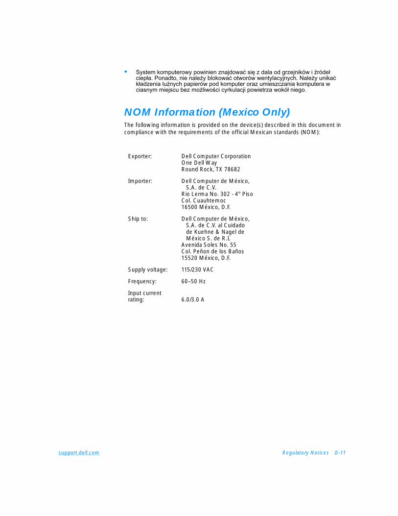
support.dell.com Regulatory Notices D-11
• System komputerowy powinien znajdować się z dala od grzejników i źródeł ciepła. Ponadto, nie nale¿y blokować otworów wentylacyjnych. Nale¿y unikać kładzenia luźnych papierów pod komputer oraz umieszczania komputera w ciasnym miejscu bez mo¿liwości cyrkulacji powietrza wokół niego.
NOM Information (Mexico Only)The following information is provided on the device(s) described in this document in compliance with the requirements of the official Mexican standards (NOM):
Exporter: Dell Computer CorporationOne Dell WayRound Rock, TX 78682
Importer: Dell Computer de México, S.A. de C.V.
Rio Lerma No. 302 - 4° PisoCol. Cuauhtemoc16500 México, D.F.
Ship to: Dell Computer de México, S.A. de C.V. al Cuidado de Kuehne & Nagel de México S. de R.I.
Avenida Soles No. 55Col. Peñon de los Baños15520 México, D.F.
Supply voltage: 115/230 VAC
Frequency: 60–50 Hz
Input currentrating: 6.0/3.0 A

D-12 Dell Inspiron 7500 System Reference and Troubleshooting Guide
Información para NOM (únicamente para México)La información siguiente se proporciona en el dispositivo o en los dispositivos descritos en este documento, en cumplimiento con los requisitos de la Norma Oficial Mexicana (NOM):
BSMI Notice (Taiwan Only)
Exportador: Dell Computer CorporationOne Dell WayRound Rock, TX 78682
Importador: Dell Computer de México, S.A. de C.V.
Rio Lerma No. 302 - 4° PisoCol. Cuauhtemoc16500 México, D.F.
Embarcar a: Dell Computer de México, S.A. de C.V. al Cuidado de Kuehne & Nagel de México S. de R.I.
Avenida Soles No. 55Col. Peñon de los Baños15520 México, D.F.
Tensión alimentación: 115/230 VAC
Frecuencia: 60–50 Hz
Consumo de corriente: 6.0/3.0 A

support.dell.com Warranty, Return Policy, and Year 2000 Statement of Compliance E-1
A P P E N D I X E
Warranty, Return Policy, and Year 2000 Statement of Compliance
Limited Three-Year Warranty (U.S. Only)Dell Computer Corporation (“Dell”) manufactures its hardware products from parts and components that are new or equivalent to new in accordance with industry-standard practices. Dell warrants that the hardware products it manufactures will be free from defects in materials and workmanship. The warranty term is three years beginning on the date of invoice, as described in the following text.
Damage due to shipping the products to you is covered under this warranty. Otherwise, this warranty does not cover damage due to external causes, including accident, abuse, misuse, problems with electrical power, servicing not authorized by Dell, usage not in accordance with product instructions, failure to perform required preventive maintenance, and problems caused by use of parts and components not supplied by Dell.
This warranty does not cover any items that are in one or more of the following categories: software; external devices (except as specifically noted); accessories or parts added to a Dell system after the system is shipped from Dell; accessories or parts added to a Dell system through Dell’s system integration department; accessories or parts that are not installed in the Dell factory; or DellWareSM products. Monitors, keyboards, and mice that are Dell-branded or that are included on Dell’s standard price list are covered under this warranty; all other monitors, keyboards, and mice (including those sold through the DellWare program) are not covered. Batteries for portable computers are covered only during the initial one-year period of this warranty.
Coverage During Year OneDuring the one-year period beginning on the invoice date, Dell will repair or replace products covered under this limited warranty that are returned to Dell’s facility. To request warranty service, you must call Dell’s Customer Technical Support within the warranty period. Refer to Chapter 5, “Getting Help,” or the section titled “Contacting Dell” in your system Help to find the appropriate telephone number for obtaining customer assistance. If warranty service is required, Dell will issue a Return Material Authorization Number. You must ship the products back to Dell in their original or equivalent packaging, prepay shipping charges, and insure the shipment or accept the

E-2 Dell Inspiron 7500 System Reference and Troubleshooting Guide
risk of loss or damage during shipment. Dell will ship the repaired or replacement products to you freight prepaid if you use an address in the continental U.S., where applicable. Shipments to other locations will be made freight collect.
NOTE: Before you ship the product(s) to Dell, back up the data on the hard-disk drive(s) and any other storage device(s) in the product(s). Remove any removable media, such as diskettes, CDs, or PC Cards. Dell does not accept liability for lost data or software.
Dell owns all parts removed from repaired products. Dell uses new and reconditioned parts made by various manufacturers in performing warranty repairs and building replacement products. If Dell repairs or replaces a product, its warranty term is not extended.
Coverage During Years Two and ThreeDuring the second and third years of this limited warranty, Dell will provide, on an exchange basis and subject to Dell’s Exchange Policy in effect on the date of the exchange, replacement parts for the Dell hardware product(s) covered under this limited warranty when a part requires replacement. You must report each instance of hardware failure to Dell’s Customer Technical Support in advance to obtain Dell’s concurrence that a part should be replaced and to have Dell ship the replacement part. Dell will ship parts (freight prepaid) if you use an address in the continental U.S. or Canada, where applicable. Shipments to other locations will be made freight collect. Dell will include a prepaid shipping container with each replacement part for your use in returning the replaced part to Dell. Replacement parts are new or reconditioned. Dell may provide replacement parts made by various manufacturers when supplying parts to you. The warranty term for a replacement part is the remainder of the limited warranty term.
You will pay Dell for replacement parts if the replaced part is not returned to Dell. The process for returning replaced parts, and your obligation to pay for replacement parts if you do not return the replaced parts to Dell, will be in accordance with Dell’s Exchange Policy in effect on the date of the exchange.
You accept full responsibility for your software and data. Dell is not required to advise or remind you of appropriate backup and other procedures.
General ProvisionsTHIS WARRANTY GIVES YOU SPECIFIC LEGAL RIGHTS WHICH VARY FROM STATE TO STATE (OR JURISDICTION TO JURISDICTION). DELL'S RESPONSIBILITY FOR MALFUNCTIONS AND DEFECTS IN HARDWARE IS LIMITED TO REPAIR AND REPLACEMENT AS SET FORTH IN THIS WARRANTY STATEMENT. ALL EXPRESS AND IMPLIED WARRANTIES FOR THE PRODUCT, INCLUDING BUT NOT LIMITED TO ANY IMPLIED WARRANTIES OF AND CONDITIONS OF MERCHANTIBILITY AND FITNESS FOR A PARTICULAR PURPOSE, ARE LIMITED IN DURATION TO THE WARRANTY PERIOD SET FORTH ABOVE AND NO WARRANTIES, WHETHER EXPRESS OR IMPLIED, WILL APPLY AFTER SUCH PERIOD.

support.dell.com Warranty, Return Policy, and Year 2000 Statement of Compliance E-3
SOME STATES (OR JURISDICTIONS) DO NOT ALLOW LIMITATIONS ON HOW LONG AN IMPLIED WARRANTY LASTS, SO THE PRECEDING LIMITATION MAY NOT APPLY TO YOU.
DELL DOES NOT ACCEPT LIABILITY BEYOND THE REMEDIES SET FORTH IN THIS WARRANTY STATEMENT OR LIABILITY FOR INCIDENTAL OR CONSEQUENTIAL DAMAGES, INCLUDING WITHOUT LIMITATION ANY LIABILITY FOR PRODUCTS NOT BEING AVAILABLE FOR USE OR FOR LOST DATA OR SOFTWARE.
SOME STATES (OR JURISDICTIONS) DO NOT ALLOW THE EXCLUSION OR LIMITATION OF INCIDENTAL OR CONSEQUENTIAL DAMAGES, SO THE PRECEDING EXCLUSION OR LIMITATION MAY NOT APPLY TO YOU.
These provisions apply to Dell’s limited three-year warranty only. For provisions of any service contract covering your system, refer to your invoice or the separate service contract that you will receive.
If Dell elects to exchange a system or component, the exchange will be made in accordance with Dell’s Exchange Policy in effect on the date of the exchange. In any instance in which Dell issues a Return Material Authorization Number, Dell must receive the product(s) for repair prior to the expiration of the warranty period in order for the repair(s) to be covered by the warranty.
NOTE: If you chose one of the available warranty and service options in place of the standard limited three-year warranty described in the preceding text, the option you chose will be listed on your invoice.
Limited Three-Year Warranty (Canada Only)Dell Computer Corporation (“Dell”) manufactures its hardware products from parts and components that are new or equivalent to new in accordance with industry-standard practices. Dell warrants that the hardware products it manufactures will be free from defects in materials and workmanship. The warranty term is three years beginning on the date of invoice, as described in the following text.
Damage due to shipping the products to you is covered under this warranty. Otherwise, this warranty does not cover damage due to external causes, including accident, abuse, misuse, problems with electrical power, servicing not authorized by Dell, usage not in accordance with product instructions, failure to perform required preventive maintenance, and problems caused by use of parts and components not supplied by Dell.
This warranty does not cover any items that are in one or more of the following categories: software; external devices (except as specifically noted); accessories or parts added to a Dell system after the system is shipped from Dell; accessories or parts added to a Dell system through Dell’s system integration department; accessories or parts that are not installed in the Dell factory; or DellWareSM products. Monitors, keyboards, and mice that are Dell-branded or that are included on Dell’s standard price list are covered under this warranty; all other monitors, keyboards, and mice (including those sold through the DellWare program) are not covered. Batteries
E-4 Dell Inspiron 7500 System Reference and Troubleshooting Guide
for portable computers are covered only during the initial one-year period of this warranty.
Coverage During Year OneDuring the one-year period beginning on the invoice date, Dell will repair or replace products covered under this limited warranty that are returned to Dell’s facility. To request warranty service, you must call Dell’s Customer Technical Support within the warranty period. Refer to Chapter 5, “Getting Help,” or the section titled “Contacting Dell” in your system Help to find the appropriate telephone number for obtaining customer assistance. If warranty service is required, Dell will issue a Return Material Authorization Number. You must ship the products back to Dell in their original or equivalent packaging, prepay shipping charges, and insure the shipment or accept the risk of loss or damage during shipment. Dell will ship the repaired or replacement products to you freight prepaid if you use an address in Canada, where applicable. Shipments to other locations will be made freight collect.
NOTE: Before you ship the product(s) to Dell, back up the data on the hard-disk drive(s) and any other storage device(s) in the product(s). Remove any removable media, such as diskettes, CDs, or PC Cards. Dell does not accept liability for lost data or software.
Dell owns all parts removed from repaired products. Dell uses new and reconditioned parts made by various manufacturers in performing warranty repairs and building replacement products. If Dell repairs or replaces a product, its warranty term is not extended.
Coverage During Years Two and ThreeDuring the second and third years of this limited warranty, Dell will provide, on an exchange basis and subject to Dell’s Exchange Policy in effect on the date of the exchange, replacement parts for the Dell hardware product(s) covered under this limited warranty when a part requires replacement. You must report each instance of hardware failure to Dell’s Customer Technical Support in advance to obtain Dell’s concurrence that a part should be replaced and to have Dell ship the replacement part. Dell will ship parts (freight prepaid) if you use an address in the continental U.S. or Canada, where applicable. Shipments to other locations will be made freight collect. Dell will include a prepaid shipping container with each replacement part for your use in returning the replaced part to Dell. Replacement parts are new or reconditioned. Dell may provide replacement parts made by various manufacturers when supplying parts to you. The warranty term for a replacement part is the remainder of the limited warranty term.
You will pay Dell for replacement parts if the replaced part is not returned to Dell. The process for returning replaced parts, and your obligation to pay for replacement parts if you do not return the replaced parts to Dell, will be in accordance with Dell’s Exchange Policy in effect on the date of the exchange.
You accept full responsibility for your software and data. Dell is not required to advise or remind you of appropriate backup and other procedures.

support.dell.com Warranty, Return Policy, and Year 2000 Statement of Compliance E-5
General ProvisionsDELL MAKES NO EXPRESS WARRANTIES OR CONDITIONS BEYOND THOSE STATED IN THIS WARRANTY STATEMENT. DELL DISCLAIMS ALL OTHER WARRANTIES AND CONDITIONS, EXPRESS OR IMPLIED, INCLUDING WITHOUT LIMITATION IMPLIED WARRANTIES AND CONDITIONS OF MERCHANTABILITY AND FITNESS FOR A PARTICULAR PURPOSE. SOME STATES (OR JURISDICTIONS) DO NOT ALLOW LIMITATIONS ON IMPLIED WARRANTIES OR CONDITIONS, SO THIS LIMITATION MAY NOT APPLY TO YOU.
DELL’S RESPONSIBILITY FOR MALFUNCTIONS AND DEFECTS IN HARDWARE IS LIMITED TO REPAIR AND REPLACEMENT AS SET FORTH IN THIS WARRANTY STATEMENT. THESE WARRANTIES GIVE YOU SPECIFIC LEGAL RIGHTS, AND YOU MAY ALSO HAVE OTHER RIGHTS, WHICH VARY FROM STATE TO STATE (OR JURISDICTION TO JURISDICTION).
DELL DOES NOT ACCEPT LIABILITY BEYOND THE REMEDIES SET FORTH IN THIS WARRANTY STATEMENT OR LIABILITY FOR INCIDENTAL OR CONSEQUENTIAL DAMAGES, INCLUDING WITHOUT LIMITATION ANY LIABILITY FOR PRODUCTS NOT BEING AVAILABLE FOR USE OR FOR LOST DATA OR SOFTWARE.
SOME STATES (OR JURISDICTIONS) DO NOT ALLOW THE EXCLUSION OR LIMITATION OF INCIDENTAL OR CONSEQUENTIAL DAMAGES, SO THE PRECEDING EXCLUSION OR LIMITATION MAY NOT APPLY TO YOU.
These provisions apply to Dell’s limited three-year warranty only. For provisions of any service contract covering your system, refer to your invoice or the separate service contract that you will receive.
If Dell elects to exchange a system or component, the exchange will be made in accordance with Dell’s Exchange Policy in effect on the date of the exchange. In any instance in which Dell issues a Return Material Authorization Number, Dell must receive the product(s) for repair prior to the expiration of the warranty period in order for the repair(s) to be covered by the warranty.
NOTE: If you chose one of the available warranty and service options in place of the standard limited three-year warranty described in the preceding text, the option you chose will be listed on your invoice.
“Total Satisfaction” Return Policy(U.S. and Canada Only)If you are an end-user customer who bought new products directly from a Dell company, you may return them to Dell within 30 days of the date of invoice for a refund or credit of the product purchase price. If you are an end-user customer who bought reconditioned or refurbished products from a Dell company, you may return them to Dell within 14 days of the date of invoice for a refund or credit of the product purchase price. In either case, the refund or credit will not include any shipping and handling charges shown on your invoice. If you are an organization that bought the products under a written agreement with Dell, the agreement may contain different terms for the return of products than specified by this policy.

E-6 Dell Inspiron 7500 System Reference and Troubleshooting Guide
To return products, you must call Dell Customer Service to receive a Credit Return Authorization Number. Refer to Chapter 5, “Getting Help,” or the section titled “Contacting Dell” in your system Help to find the appropriate telephone number for obtaining customer assistance. To expedite the processing of your refund or credit, Dell expects you to return the products to Dell in their original packaging within five days of the date that Dell issues the Credit Return Authorization Number. You must also prepay shipping charges and insure the shipment or accept the risk of loss or damage during shipment. You may return software for refund or credit only if the sealed package containing the diskette(s) or CD(s) is unopened. Returned products must be in as-new condition, and all of the manuals, diskette(s), CD(s), power cables, and other items included with a product must be returned with it. For customers who want to return, for refund or credit only, either applications software or an operating system that has been installed by Dell, the whole system must be returned, along with any media and documentation that may have been included in the original shipment.
This “Total Satisfaction” Return Policy does not apply to DellWare products, which may be returned under DellWare's then-current return policy. In addition, reconditioned parts purchased through Dell Spare Parts Sales in Canada are nonreturnable.
Year 2000 Statement of Compliance for Dell-Branded Hardware ProductsDell-branded hardware products shipped on or after January 1, 1997, are eligible to carry the “NSTL Hardware Tested Year 2000 Compliant” logo by virtue of formal testing with, and successful completion of, the National Software Testing Laboratories (NSTL) YMARK2000 test.* Dell will treat a failure to pass the YMARK2000 test as a covered event under Dell's warranty for the product, subject to the normal warranty limitations.** For a complete copy of Dell's warranty, see the product's documentation. Dell-branded hardware products will also recognize the year 2000 as a leap year.
*The YMARK2000 standard tests the ability of system hardware and firmware to support the transition to the year 2000 (and to recognize leap years, when appropriate, for years 2000 through 2009 inclusive) and not that of options, operating systems, or applications software. Dell-branded hardware products that pass the YMARK2000 test conform to BSI-DISC PD 2000-1.
** Except for this clarification of Dell's warranty for NSTL logo hardware, all other warranties, conditions and remedies, express or implied, relating to year 2000 readiness or compliance are disclaimed. To make a claim under this warranty for NSTL logo hardware, customers must contact Dell prior to January 1, 2001. To make a claim, write to:
Dell Computer CorporationP.O. Box 149258Austin, Texas 78714-9258Attention: Year 2000
support.dell.com Warranty, Return Policy, and Year 2000 Statement of Compliance E-7
Despite a system's ability to pass the YMARK2000 test, actual rollover results in specific operating environments may vary depending on other factors including, but not limited to, other hardware, operating systems, and applications software.
Previous ProductsFor Dell-branded hardware products shipped prior to January 1, 1997, that have an upgradable basic input/output system (BIOS), Dell makes available a BIOS upgrade. Although these products may not have been tested under the YMARK2000 test, Dell believes that the hardware would pass the YMARK2000 test, provided the appropriate BIOS upgrade is properly loaded.
For Dell-branded hardware products that do not have an upgradable BIOS, Dell has made available, as a convenience to customers, the Dell Program Patch, a software utility designed to assist customers in managing the year 2000 rollover.
SoftwareDell specifically excludes all non-Dell-developed software from this compliance statement. All software run on Dell-branded hardware products should be independently verified by customers to be year 2000-compliant.
The factory-installed software on your system is the current version provided by the software manufacturer and is validated by Dell for installation. Dell recommends that you check each software manufacturer’s year 2000 Web site for updates to their products. Links to a number of these Web sites can be found at the Dell year 2000 Web sites.
Additional InformationFor additional information on year 2000 compliance of Dell-branded hardware products, refer to the following Dell year 2000 Web sites, or contact a Dell customer service representative in your area:
• http://www.dell.com/year2000 (Americas)
• http://www.dell.com/jp/year2000 (Japan)
• http://www.euro.dell.com/year2000 (Europe)
• http://www.dell.com/ap/year2000/index.htm (Asia Pacific)
Macrovision Product NoticeThe following product notice applies to the Macrovision Corporation product that is included with the DVD-ROM drive:
This product incorporates copyright protection technology that is protected by method claims of certain U.S. patents and other intellectual property rights owned by Macrovision Corporation, and it is intended for home and other limited viewing uses only unless otherwise authorized by Macrovision Corporation. Reverse engineering or disassembly is prohibited.

E-8 Dell Inspiron 7500 System Reference and Troubleshooting Guide

support.dell.com Index 1
Index
Aassistance
technical, 5-1telephone numbers, 5-7warranty repair or credit, 5-4
audio functionstroubleshooting, 3-29
AutoTech service, 5-3
Bbattery, 1-1
beep codesSee also error messagesabout, C-4
BIOS, 1-2
boot routine, 3-2indications, 3-6
Ccables
troubleshooting, 3-2
cache memory, 1-1
calling Dell, 5-7
cautions, xii
CD-ROM drivetroubleshooting, 3-17
CD-ROM drivestroubleshooting, 3-4
computertechnical specifications, A-1
connectorstroubleshooting, 3-2
DDell Diagnostics, 3-29
diagnosing problems, 5-1
Diagnostics Checklist, 5-6
diagnostics. See Dell Diagnostics
diskette drivefailure during POST, 3-16
diskette drivestroubleshooting, 3-4
displayabout, 1-1, 1-3location, 1-3troubleshooting, 3-22
display close/suspend button, 1-3
display latch, 1-3
driversas source of program conflicts, 3-9
2 Dell Inspiron 7500 System Reference and Troubleshooting Guide
drivestroubleshooting, 3-4
dropped or damaged computer, 3-12
EECP-compatible devices, B-6
electrostatic discharge. See ESD
error messagesbeep codes, C-4system error messages, C-1table, C-1
ESD, ix
Extended Capabilities Port, B-6
Ffailures
troubleshooting, 3-1
fixing problems, 5-1
Ggetting help, 5-1
grounding procedure, ix, 3-1
Hhard-disk drives
power management, B-9troubleshooting, 3-4, 3-18
hardware features, 1-1
help toolsAutoTech service, 5-3Internet, 5-2TechConnect BBS, 5-3TechFax service, 5-3
II/O
troubleshooting functions, 3-27
indicator light, 1-3
infrared portabout, 1-2troubleshooting, 3-28
installing the system Help for Windows 98, 4-6, 4-13
installing the system Help for Windows NT, 4-13
Internet help tools, 5-2
interrupt assignment conflicts, 3-9
IRQ line assignment, 3-9
Kkeyboard
about, 1-3checking external keyboard during
POST, 3-20
keys and key combinationsDell Diagnostics, 3-32
Llithium-ion battery, 1-1
Mmain battery, 1-3
media bay, 1-3
MegaBay, 1-2
memoryfailure during POST, 3-21
messagesbeep codes, C-4error messages, 3-8
support.dell.com Index 3
microphone, 1-3
microprocessorabout, 1-1
monitor (external)errors during POST, 3-23
monitor connector, 1-2
mouse, 1-2
Nnotational conventions, xii
notes, xii
NVRAM, B-1
Ooptions, 1-7
Pparallel port
troubleshooting, 3-25
parallel printertroubleshooting, 3-26
passwords. See system password
PC Cards, 1-2
POSTCD-ROM drive check, 3-17diskette drive check, 3-16external keyboard check, 3-20external monitor check, 3-23hard-disk drive check, 3-18memory check, 3-21
power button, 1-3
power failureAC power, 3-14battery power, 3-14cable connections, 3-2
power failure (continued)partial, 3-16troubleshooting, 3-13
power managementmodes, 1-2save-to-disk suspend mode, 1-2
problemsdiagnosing, 3-1help tools, 5-1troubleshooting, 3-1with your order, 5-4
product information, 5-4
PS/2connector, 1-2
RRAM count failure during POST, 3-21
regulatory notices, D-2
return policy, E-5
returns, 5-4
Ssafety instructions
ESD prevention, ixworking inside your computer, ix
save-to-disk suspend mode, 1-2
serial devicestroubleshooting, 3-27
serial porttroubleshooting, 3-25
service, 5-1
Setup messages, B-1
Setup programabout, B-1accessing, B-2Boot menu options, B-11Exit menu options, B-12
4 Dell Inspiron 7500 System Reference and Troubleshooting Guide
Setup program (continued)Main menu options, B-2Power menu options, B-8Security menu options, B-7System Devices menu options, B-4
softwaredrivers, 3-9error messages, 3-8for configuring system, B-1included with computer, 1-7installing and configuring, 3-7memory-resident programs, 3-8problems, 3-7program conflicts, 3-9start-up files, 3-8troubleshooting errors, 3-7using, 3-8virus scans, 3-7
software features, 1-7
speakerslocation, 1-3
specificationstechnical, A-1
standby mode, 1-2
start-up files, 3-8
supporttechnical, 5-1
systemspecifications, A-1
system error messagesSee also error messagesabout, C-1
system memory, 1-2
system passwordassigning or changing, B-7
TTechConnect BBS, 5-3
TechFax service, 5-3
technical assistanceobtaining, 5-1warranty repair or credit, 5-4
technical specifications, A-1
touch padabout, 1-2location, 1-3troubleshooting, 3-28
troubleshootingabout, 3-1AC power failure, 3-14audible signs of problems, 3-5audio functions, 3-29basic problems, 3-1battery power failure, 3-14beep codes, C-4CD-ROM drive, 3-17checking connections, 3-2Diagnostics Checklist, 5-6diskette drive failure during POST, 3-16display failure, 3-22drives, 3-4dropped or damaged computer, 3-12DVD-ROM drive, 3-17environmental factors, 3-3external keyboard, 3-20external monitor, 3-23failure during RAM count, 3-21hard-disk drive failure during POST,
3-18I/O functions, 3-25infrared port, 3-28Internet tools, 5-2IRQ conflicts, 3-9modem, 3-4monitor, 3-23parallel port, 3-25parallel printer, 3-26partial power failure, 3-16power, 3-3serial devices, 3-27serial port, 3-25software errors, 3-7touch pad, 3-28
support.dell.com Index 5
troubleshooting (continued)water damage, 3-10where to start, 3-1
TSR programsabout, 3-7problems with, 3-8
typographical conventions, xiii
UUniversal Serial Bus. See USB
upgrade options, 1-7
upgrades, 1-7
USB, 1-3
user’s documentation, xii
Vvideo display, 1-1
video memory, A-3
Wwarnings, xii
warranty information, xii, E-1, E-3
warranty repair or credit, 5-4
water damage, 3-10
World Wide Web help tools, 5-2
XXGA display, 1-1

6 Dell Inspiron 7500 System Reference and Troubleshooting Guide