Embed Size (px)
Citation preview

Feeder protection and controlREF620 ANSIProduct guide
Relion® 620 series

2 Feeder protection and control REF620 | Product guide
Table of contents
1. Description .......................................................................................................................................................................... 3
2. Standard configurations ...................................................................................................................................................... 4
3. Protection functions .......................................................................................................................................................... 11
4. Application ......................................................................................................................................................................... 11
5. Supported ABB solutions .................................................................................................................................................. 11
6. Control ............................................................................................................................................................................... 13
7. Measurements ................................................................................................................................................................... 13
8. Digital fault recorder .......................................................................................................................................................... 13
9. Events recorder ................................................................................................................................................................. 13
10. Recorded data ................................................................................................................................................................. 13
11. Circuit-breaker condition monitoring ............................................................................................................................... 13
12. Trip-circuit monitoring ..................................................................................................................................................... 13
13. Self diagnostics ............................................................................................................................................................... 13
14. Fuse failure protection ..................................................................................................................................................... 13
15. Current circuit supervision ............................................................................................................................................... 14
16. Load profile recording ...................................................................................................................................................... 14
17. Power quality ................................................................................................................................................................... 14
18. Single-line diagram (SLD) ................................................................................................................................................ 14
19. Cable fault detection (CFD) .............................................................................................................................................. 14
20. Access control ................................................................................................................................................................. 14
21. Inputs and outputs ........................................................................................................................................................... 14
22. Communications .............................................................................................................................................................. 16
23. Technical data .................................................................................................................................................................. 18
24. Display ............................................................................................................................................................................. 44
25. Local HMI ........................................................................................................................................................................ 44
26. Mounting methods ........................................................................................................................................................... 44
27. Accessories and ordering data ........................................................................................................................................ 45
28. Tools ................................................................................................................................................................................ 47
29. Terminal diagrams ............................................................................................................................................................ 48
30. Certificates ...................................................................................................................................................................... 59
31. References ....................................................................................................................................................................... 59
32. Functions, codes and symbols ........................................................................................................................................ 59
33. Document revision history ............................................................................................................................................... 61
34. Notes ............................................................................................................................................................................... 62

Product guide | Feeder protection and control REF620 3
1. Description
The REF620 is a dedicated feeder IED perfectly aligned for the
protection, control, measurement and supervision of utility sub-
stations and industrial power systems.
REF620 is a member of ABB’s Relion® family and a part of its
620 protection and control product series. The 620 series IEDs
are characterized by flexibility and performance for demanding
utility distribution and industrial applications. Engineered from
the ground up, the 620 series has been designed to unleash the
full potential of the IEC 61850 standard for communication and
interoperability of substation automation devices.
Unique REF620 ANSI features
− Six setting groups
− Drawout design
− Underground, overhead cable fault detection (CFD)
− High-speed (< 1 ms) outputs
− High impedance (HIZ) fault detection
− Arc flash detection (AFD)
− Phase step distance protection
− Power quality
− Ring-lug terminals for all inputs and outputs
− Large, easy to read LCD screen
− Programmable push-buttons
− Environmentally friendly design with RoHS Compliance
The REF620 provides main protection for overhead lines,
cable feeders, and busbar systems of distribution substations.
It can be applied for protection and control of grounded and
ungrounded distribution systems. It offers support for single
breaker, one-and-half breaker and double breaker feeder config-
urations. Flexible order coding allows for choosing current-only
or current-and-voltage configurations to best fit your distribution
feeder application needs.
The REF620 is the most powerful, advanced and simplest
feeder protection relay in its class, perfectly offering time and
instantaneous overcurrent, negative sequence overcurrent,
phase step distance, phase discontinuity, breaker failure, ther-
mal overload, and voltage metering and protection. The relay
also features high impedance fault (HIZ) and sensitive earth
fault (SEF) protection for grounded and ungrounded distribu-
tion systems. Also, the relay incorporates a flexible three-phase
multi-shot auto-reclose function for automatic feeder restoration
in temporary faults on overhead lines.
Enhanced with safety options, the relay offers a three-channel
arc-fault detection system for supervision of the switchgear. The
REF620 also integrates basic control functionality, which facili-
tates the control of up to 2 circuit breakers via the relay’s front
panel human machine interface (HMI) or remote control system.
To protect the relay from unauthorized access and to maintain
the integrity of information, the relay has been provided with a
four-level, role-based user authentication system, with individual
passwords for the viewer, operator, engineer, and administrator
levels. The access control system applies to the front panel
HMI, embedded web browser based HMI, and the
PCM600, Protection and Control IED Manager.
REF620 genuinely supports the new IEC 61850 standard for
inter-device communication in substations. The relay also sup-
ports the industry standard DNP3 and Modbus® protocols. For
accurate time stamping, REM620 supports synchronization over
Ethernet using SNTP or over a separate bus using IRIG-B.

4 Feeder protection and control REF620 | Product guide
2. Standard configurations
The REF620 relay main application is feeder protection and
control and offers three standard configurations whose relay
functions and features are based on the needs of the applica-
tion. See Tables 1 and 2 for details. Configuration A comprises
protection scheme useful in enhanced utility and industrial
feeder protection with single breaker . Configuration B includes
functions and features for comprehensive feeder protection and
control applications in with one-and-half breaker configuration .
Configuration C includes functions and features for comprehen-
sive feeder protection and control applications in with 2 breaker
configuration.
Figures 1 through 3 show the protection functions available for
the three standard confi gurations and available analog inputs
within each configuration. See section Selection and ordering
data for details on the available analog inputs for each standard
configuration.
Figure 1. REF620 ANSI Functional Application A
3
79-1
46PD-137-149F-1
50G-1151G1
1 Available with 5A/1A Ground CT option, Appl A(AA)2 Available with 1A/0.2A SEF/HIZ CT option Appl A(AB) (need CBCT input)3 Available with Arc Flash Detection(AFD) option4 Available with Power Quality option5 50G BF-1 is part of 50BF-1 function6 Functions 32N-1, 67/51N, 67/50N-1, 67/50N-2 have following options
a) Directionality by either Negative seq or Zero seq. volt polarization.The latter needs WYE VT input to the IED.
b) Operating current can be either calculated IN based on phase side currents or measured current at IG input
3
52
AFD-33AFD-13 AFD-23
3
Υ or V
27-2
27-1
59-1
59-2
47-1
50N-1
51LT
51N-1
50 SEF2
47-2
81-1
81-2
81LSH-1
81LSH-2
46-2
50N-2 50N-3
50G-21 50G-31
67/51P 67/50P-1
67/50P-232P-150
BF-1
87LOZREF1
21P
59G51P 50P-1 50P-350P-2 46-1 LoadProf.
59N-1
25-1
60-1
PQ-14
REF620 V2.0 ANSI Func Appl A
IG
IA, IB, IC
VA, VB, VC VG
Vsync
HIZ2
50GBF-15
32N-16 67/51N6
67/50N-16
67/50N-26
Bus

Product guide | Feeder protection and control REF620 5
Figure 2. REF620 V4.0 ANSI Functional Applications B
27-1 (2)
27-2 (2)
47-1 (2)
47-2 (2)
59-1 (2)
59-2 (2)
27-1 (1)
27-2 (1)
47-1 (1)
47-2 (1)
59-1 (1)
59-2 (1)
60-1 (2)
60-1 (1)
25-3
67/50P-1
67/50P-2
67/51P21P-149F-1
51P 50P-1 50P-2 50P-3 46-1 46PD
LoadProf. 32P-1
81-281-181LSH-2
81LSH-1
50N-3
50N-2
50N-1
51N-1
25-1
25-2
24-1PQ-12
37-1
AFD-31
52-1 52-352-2F1
F2
50BF-1
Σ
50BF-2
2 or 3
Υ or V
2 or 3
Υ or V
33
79-1 (1)
79-2 (2)
59N-1 (1)
59N-1 (2)
Bus 1Bus 2
Switch
(1)
(2)
46-2
REF620 V2.0 ANSI Func Appl B
AFD-11
AFD-21
(1) (2)
VA(2), VB(2), VC(2)
VA, VB, VC
IA, IB, IC
IA(1
), IB
(1),
IC(1
)
IA(2), IB(2), IC(2)
Vsyn
c(1)
Vsyn
c(2)
1 Available with Arc Flash Detection (AFD) option. When current supervision is set, current considered is from main CT (1)2 Available with Power Quality option3 Functions 32N-1, 67/51N, 67/50N-1, 67/50N-N have the option to select directionality by either Negative seq or Zero seq. volt polarization. The latter needs WYE VT input to the IED.
67/50N-13
67/51N3
67/50N-23 32N-13
51LT

6 Feeder protection and control REF620 | Product guide
27-1 (2)
27-2 (2)
47-1 (2)
47-2 (2)
59-1 (2)
59-2 (2)
27-1 (1)
27-2 (1)
47-1 (1)
47-2 (1)
59-1 (1)
59-2 (1)
60-1 (2)
60-1 (1)
25-3
67/50P-1
67/50P-2
67/51P21P-149F-1
51P 50P-1 50P-2 50P-3 46-1 46PD
LoadProf. 32P-1
81-281-181LSH-2
81LSH-1
50N-2
50N-1
51N-1
25-1
25-2
24-1PQ-1437-1
AFD-33
52-1 52-2F1
50BF-1
Σ
50BF-2
2 or 3
Υ or V
2 or 3
Υ or V
33
79-1 (1)
79-2 (2)
59N-1 (1)
59N-1 (2)
Bus 1 Bus 2
Switch
(1)
(2)
46-2
REF620 V2.0 ANSI Func Appl C
AFD-13
AFD-23
(1) (2)
VA(2), VB(2), VC(2)
VA, VB, VC
IA, IB, IC
IA(2), IB(2), IC(2)
Vsyn
c
IA(1
), IB
(1),
IC(1
)
50G-31
50G-21
50G-1151G1
67/51N5
67/50N-15
IG
67/50N-2532N-15
50N-3
1 Available with 5A/1A Ground CT option, Appl C(CA)2 Available with 1A/0.2A SEF/HIZ CT option, Appl C(CB) (need CBCT input)3 Available with Arc Flash Detection (AFD) option.When current supervision is set, current considered is from main CT (1)
4 Available with Power Quality option5 Functions 32N-1, 67/51N, 67/50N-1, 67/50N-2 have following options
a) Directionality by either Negative seq or Zero seq. volt polarization.The latter needs WYE VT input to the IED.
b) Operating current can be either calculated IN based on phase side currents or measured current at IG input
50 SEF2 HIZ2
51LT
Figure 3. REF620 V4.0 ANSI Functional Applications C
Product guide | Feeder protection and control REF620 7
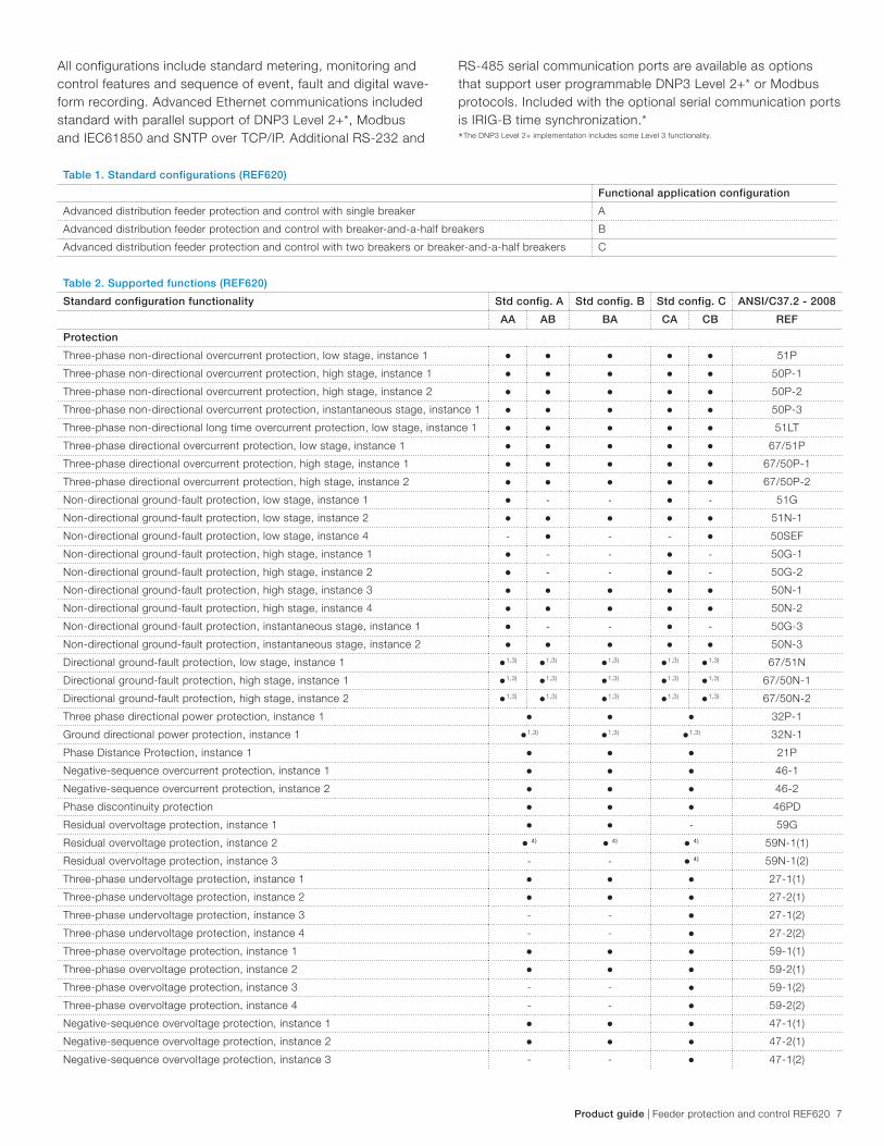
All configurations include standard metering, monitoring and
control features and sequence of event, fault and digital wave-
form recording. Advanced Ethernet communications included
standard with parallel support of DNP3 Level 2+*, Modbus
and IEC61850 and SNTP over TCP/IP. Additional RS-232 and
RS-485 serial communication ports are available as options
that support user programmable DNP3 Level 2+* or Modbus
protocols. Included with the optional serial communication ports
is IRIG-B time synchronization.*
*The DNP3 Level 2+ implementation includes some Level 3 functionality.
Table 1. Standard configurations (REF620)
Functional application configuration
Advanced distribution feeder protection and control with single breaker A
Advanced distribution feeder protection and control with breaker-and-a-half breakers B
Advanced distribution feeder protection and control with two breakers or breaker-and-a-half breakers C
Table 2. Supported functions (REF620)
Standard configuration functionality Std config. A Std config. B Std config. C ANSI/C37.2 - 2008
AA AB BA CA CB REF
Protection
Three-phase non-directional overcurrent protection, low stage, instance 1 ● ● ● ● ● 51P
Three-phase non-directional overcurrent protection, high stage, instance 1 ● ● ● ● ● 50P-1
Three-phase non-directional overcurrent protection, high stage, instance 2 ● ● ● ● ● 50P-2
Three-phase non-directional overcurrent protection, instantaneous stage, instance 1 ● ● ● ● ● 50P-3
Three-phase non-directional long time overcurrent protection, low stage, instance 1 ● ● ● ● ● 51LT
Three-phase directional overcurrent protection, low stage, instance 1 ● ● ● ● ● 67/51P
Three-phase directional overcurrent protection, high stage, instance 1 ● ● ● ● ● 67/50P-1
Three-phase directional overcurrent protection, high stage, instance 2 ● ● ● ● ● 67/50P-2
Non-directional ground-fault protection, low stage, instance 1 ● - - ● - 51G
Non-directional ground-fault protection, low stage, instance 2 ● ● ● ● ● 51N-1
Non-directional ground-fault protection, low stage, instance 4 - ● - - ● 50SEF
Non-directional ground-fault protection, high stage, instance 1 ● - - ● - 50G-1
Non-directional ground-fault protection, high stage, instance 2 ● - - ● - 50G-2
Non-directional ground-fault protection, high stage, instance 3 ● ● ● ● ● 50N-1
Non-directional ground-fault protection, high stage, instance 4 ● ● ● ● ● 50N-2
Non-directional ground-fault protection, instantaneous stage, instance 1 ● - - ● - 50G-3
Non-directional ground-fault protection, instantaneous stage, instance 2 ● ● ● ● ● 50N-3
Directional ground-fault protection, low stage, instance 1 ●1,3) ●1,3) ●1,3) ●1,3) ●1,3) 67/51N
Directional ground-fault protection, high stage, instance 1 ●1,3) ●1,3) ●1,3) ●1,3) ●1,3) 67/50N-1
Directional ground-fault protection, high stage, instance 2 ●1,3) ●1,3) ●1,3) ●1,3) ●1,3) 67/50N-2
Three phase directional power protection, instance 1 ● ● ● 32P-1
Ground directional power protection, instance 1 ●1,3) ●1,3) ●1,3) 32N-1
Phase Distance Protection, instance 1 ● ● ● 21P
Negative-sequence overcurrent protection, instance 1 ● ● ● 46-1
Negative-sequence overcurrent protection, instance 2 ● ● ● 46-2
Phase discontinuity protection ● ● ● 46PD
Residual overvoltage protection, instance 1 ● ● - 59G
Residual overvoltage protection, instance 2 ● 4) ● 4) ● 4) 59N-1(1)
Residual overvoltage protection, instance 3 - - ● 4) 59N-1(2)
Three-phase undervoltage protection, instance 1 ● ● ● 27-1(1)
Three-phase undervoltage protection, instance 2 ● ● ● 27-2(1)
Three-phase undervoltage protection, instance 3 - - ● 27-1(2)
Three-phase undervoltage protection, instance 4 - - ● 27-2(2)
Three-phase overvoltage protection, instance 1 ● ● ● 59-1(1)
Three-phase overvoltage protection, instance 2 ● ● ● 59-2(1)
Three-phase overvoltage protection, instance 3 - - ● 59-1(2)
Three-phase overvoltage protection, instance 4 - - ● 59-2(2)
Negative-sequence overvoltage protection, instance 1 ● ● ● 47-1(1)
Negative-sequence overvoltage protection, instance 2 ● ● ● 47-2(1)
Negative-sequence overvoltage protection, instance 3 - - ● 47-1(2)

8 Feeder protection and control REF620 | Product guide
Table 2. Supported functions (REF620)
Standard configuration functionality Std config. A Std config. B Std config. C ANSI/C37.2 - 2008
AA AB BA CA CB REF
Protection
Negative-sequence overvoltage protection, instance 4 - - ● 47-2(2)
Frequency protection, instance 1 ● ● ● 81-1
Frequency protection, instance 2 ● ● ● 81-2
Voltage per hertz protection, instance 1 ● ● ● ● ● 24
Three-phase thermal protection for feeders, cables and distribution transformers,
Instance 1
● ● ● ● 49F
Numerical stabilized low impedance restricted ground-fault protection ● - - - - 87LOZREF
Phase current sets summing function - - ● ● ● CSUM
Three phase measurement switching - - ● ● ● VSWI
Circuit breaker failure protection, instance 1 ● ● ● ● ● 50BF-1
Circuit breaker failure protection, instance 2 - - ● ● ● 50BF-2
Three-phase inrush detector, instance 1 ● ● ● ● ● INR
Master trip, instance 1 ● ● ● ● ● 86/94-1
Master trip, instance 2 ● ● ● ● ● 86/94-2
Arc protection, instance 1 ● ● ● ● ● AFD-1
Arc protection, instance 2 ● ● ● ● ● AFD-2
Arc protection, instance 3 ● ● ● ● AFD-3
High impedance fault detection - ● - - ● HIZ
Load shedding and restoration, instance 1 ● ● ● ● ● 81LSH-1
Load shedding and restoration, instance 2 ● ● ● ● ● 81LSH-2
Loss of phase, instance 1 ● ● ● ● ● 37-1
Control
Circuit-breaker control, instance 1 ● ● ● ● ● 52-1
Circuit-breaker control, instance 2 - - ● ● ● 52-2
Auto-reclosing, instance 1 ● ● ● ● ● 79-1
Auto-reclosing, instance 2 - - ● ● ● 79-2
Synchronism and energizing check, instance 1 ● ● ● ● ● 25-1
Synchronism and energizing check, instance 2 - - ● ● ● 25-2
Synchronism and energizing check, instance 3 - - ● ● ● 25-3
Condition Monitoring
Circuit-breaker condition monitoring, instance 1 ● ● ● ● ● 52CM-1
Circuit-breaker condition monitoring, instance 2 - - ● ● ● 52CM-2
Trip circuit supervision, instance 1 ● ● ● ● ● TCM-1
Trip circuit supervision, instance 2 ● ● ● ● ● TCM-2
Current circuit supervision ● ● - ● - CCM
Fuse failure supervision, instance 1 ● ● ● ● ● 60-1
Fuse failure supervision, instance 2 - - ● ● ● 60-2
Cable fault detection ● ● ● ● ● CFD
Measurement
Three-phase current measurement, instance 1 ● ● ● ● ● IA, IB, IC
Sequence current measurement, instance 1 ● ● ● ● ● I1, I2, I0
Residual current measurement, instance 1 ● ● - ● - IG
Three-phase voltage measurement, instance 1 ● ● ● ● ● VA, VB, VC
Three-phase voltage measurement, instance 2 - - ● ● ● VA, VB, VC (2)
Residual voltage measurement, instance 1 ● ● - - - VG
Sequence voltage measurement, instance 1 ● ● ● ● ● V1, V2, V0
Sequence voltage measurement, instance 2 - - ● ● ● V1, V2, V0 (2)
Single-phase power and energy measurement, instance 1 ● ● ● ● ● SP, SE-1
Three-phase power and energy measurement, instance 1 ● ● ● ● ● P, E-1
Load profile ● ● ● ● LoadProf
Frequency measurement, instance 1 ● ● ● ● ● f
Product guide | Feeder protection and control REF620 9
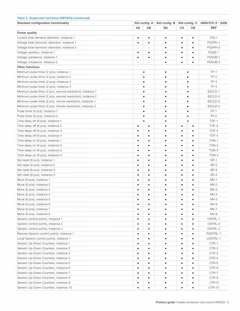
Table 2. Supported functions (REF620) (continued)
Standard configuration functionality Std config. A Std config. B Std config. C ANSI/C37.2 - 2008
AA AB BA CA CB REF
Power quality
Current total demand distortion, instance 1 ● ● ● ● ● PQI-1
Voltage total harmonic distortion, instance 1 ● ● ● ● ● PQVPH-1
Voltage total harmonic distortion, instance 2 - - ● ● ● PQVPH-2
Voltage variation, instance 1 ● ● ● ● ● PQSS-1
Voltage unbalance, instance 1 ● ● ● ● ● PQVUB-1
Voltage unbalance, instance 2 - - ● ● ● PQVUB-2
Other functions
Minimum pulse timer (2 pcs), instance 1 ● ● ● TP-1
Minimum pulse timer (2 pcs), instance 2 ● ● ● TP-2
Minimum pulse timer (2 pcs), instance 3 ● ● ● TP-3
Minimum pulse timer (2 pcs), instance 4 ● ● ● TP-4
Minimum pulse timer (2 pcs, second resolution), instance 1 ● ● ● 62CLD-1
Minimum pulse timer (2 pcs, second resolution), instance 2 ● ● ● 62CLD-3
Minimum pulse timer (2 pcs, minute resolution), instance 1 ● ● ● 62CLD-2
Minimum pulse timer (2 pcs, minute resolution), instance 2 ● ● ● 62CLD-4
Pulse timer (8 pcs), instance 1 ● ● ● PT-1
Pulse timer (8 pcs), instance 2 ● ● ● PT-2
Time delay off (8 pcs), instance 1 ● ● ● TOF-1
Time delay off (8 pcs), instance 2 ● ● ● ● ● TOF-2
Time delay off (8 pcs), instance 3 ● ● ● ● ● TOF-3
Time delay off (8 pcs), instance 4 ● ● ● ● ● TOF-4
Time delay on (8 pcs), instance 1 ● ● ● ● ● TON-1
Time delay on (8 pcs), instance 2 ● ● ● ● ● TON-2
Time delay on (8 pcs), instance 3 ● ● ● ● ● TON-3
Time delay on (8 pcs), instance 4 ● ● ● ● ● TON-4
Set reset (8 pcs), instance 1 ● ● ● ● ● SR-1
Set reset (8 pcs), instance 2 ● ● ● ● ● SR-2
Set reset (8 pcs), instance 3 ● ● ● ● ● SR-3
Set reset (8 pcs), instance 4 ● ● ● ● ● SR-4
Move (8 pcs), instance 1 ● ● ● ● ● MV-1
Move (8 pcs), instance 2 ● ● ● ● ● MV-2
Move (8 pcs), instance 3 ● ● ● ● ● MV-3
Move (8 pcs), instance 4 ● ● ● ● ● MV-4
Move (8 pcs), instance 5 ● ● ● ● ● MV-5
Move (8 pcs), instance 6 ● ● ● ● ● MV-6
Move (8 pcs), instance 7 ● ● ● ● ● MV-7
Move (8 pcs), instance 8 ● ● ● ● ● MV-8
Generic control points, instance 1 ● ● ● ● ● CNTRL-1
Generic control points, instance 2 ● ● ● ● ● CNTRL-2
Generic control points, instance 3 ● ● ● ● ● CNTRL-3
Remote Generic control points, instance 1 ● ● ● ● ● RCNTRL-1
Local Generic control points, instance 1 ● ● ● ● ● LCNTRL-1
Generic Up-Down Counters, instance 1 ● ● ● ● ● CTR-1
Generic Up-Down Counters, instance 2 ● ● ● ● ● CTR-2
Generic Up-Down Counters, instance 3 ● ● ● ● ● CTR-3
Generic Up-Down Counters, instance 4 ● ● ● ● ● CTR-4
Generic Up-Down Counters, instance 5 ● ● ● ● ● CTR-5
Generic Up-Down Counters, instance 6 ● ● ● ● ● CTR-6
Generic Up-Down Counters, instance 7 ● ● ● ● ● CTR-7
Generic Up-Down Counters, instance 8 ● ● ● ● ● CTR-8
Generic Up-Down Counters, instance 9 ● ● ● ● ● CTR-9
Generic Up-Down Counters, instance 10 ● ● ● ● ● CTR-10

10 Feeder protection and control REF620 | Product guide
Table 2. Supported functions (REF620) (continued)
Standard configuration functionality Std config. A Std config. B Std config. C ANSI/C37.2 - 2008
AA AB BA CA CB REF
Other functions
Generic Up-Down Counters, instance 11 ● ● ● ● ● CTR-11
Generic Up-Down Counters, instance 12 ● ● ● ● ● CTR-12
Programmable buttons(16 buttons), instance 1 ● ● ● ● ● FKEY1
Logging functions
Disturbance recorder ● ● ● ● ● DFR
Fault recorder ● ● ● ● ● FR
Sequence event recorder ● ● ● ● ● SER
Fault location ● ● ● ● ● FLO
1) Io selectable by parameter, I2 as default
2) Calculated neutral current is always used
3) Vo calculated and negative sequence voltage selectable by parameter, V2 as default
4) Vo calculated is always used

Product guide | Feeder protection and control REF620 11
3. Protection functions
Th is IED provides non-directional phase and ground overcur-
rent, phase step distance, thermal overload, phase unbalance
and phase discontinuity protection with sensitive earth fault
(SEF), high impedance fault detection (HIZ), directional phase,
ground and neutral overcurrent and phase, ground (residual),
positive sequence and negative sequence undervoltage and
overvoltage protection. Also, the IED offers three-pole multishot
autoreclose function for utility overhead distribution feeders. En-
hanced with an arc fl ash detection (AFD), the relay also features
three light detection channels for arc fault detection of the cir-
cuit breaker, busbar and cable compartment of metal-enclosed
switchgear. The AFD sensor interface is available on the optional
communication module. Fast tripping increases
personal safety and limits material damage within the
switchgear in an arc fault situation.
4. Application
The REF620 offers users maximum fexibility of application with
three standard confgurations A, B and C. Each configuration
allows users convenient ordering selections to perfectly match
available analog inputs (AI) and binary inputs and outputs
(I/O) required in their distribution feeder protection and control
designs. All configurations include the customer programmable
phase and ground CT and, where applicable, VT second-
ary nominal settings plus wide protection setting ranges that
increase the REF620 flexibility of application and eliminate need
for multiple different feeder relay order codes. Here are the de-
scriptions of each of the three configurations available:
A: Advanced distribution feeder protection and control with
single breaker
B: Advanced distribution feeder protection and control with
breaker-and-a-half bus system
C Advanced distribution feeder protection and control with two
breakers or breaker-and-a-half bus system
In addition to protection, control and metering, each configura-
tion includes many features standard for comprehensive utility
and industrial distribution feeder schemes including graphical
user-programmable logic, digital fault (waveform), sequence of
events (SOE) and fault recording, monitoring, load profile and
advanced Ethernet communications supporting IEC61850-8
with GOOSE (peer-to-peer) messaging and DNP3 Level 2+
and Modbus protocols over TCP/IP. Valuable options include
serial communications supporting DNP3 Level 2+ and Modbus
protocols, Power Quality, Spanish or Portuguese menu/WebHMI
language, and Arc Flash Detection safety feature. Costly bus
diff erential protection and bus transfer control schemes due to
dedicated CTs, I/O wiring and special communication cables
are now affordable with the 620 series relays’ standard Ethernet
communications. Using peer-to-peer communications via IEC-
61850’s GOOSE messaging affords integration of high-speed
monitoring and control applications.
5. Supported ABB solutions
ABB’s 620 series protection and control IEDs together with
the COM600 Station Automation device constitute a genuine
IEC 61850 solution for reliable power distribution in utility and
industrial power systems. To facilitate and streamline the system
engineering ABB’s IEDs are supplied with Connectivity Pack-
ages containing a compilation of software and IED-specific
information including single-line diagram templates, a full IED
data model including event and parameter lists. By utilizing the
Connectivity Packages the IEDs can be readily configured via
the PCM600 Protection and Control IED Manager and inte-
grated with the COM600 Station Automation device or the
MicroSCADA Pro network control and management system.
The 620 series IEDs offer native support for the IEC 61850 stan-
dard also including horizontal GOOSE messaging. Compared
with traditional hard-wired inter-device signaling, peer-to-peer
communication over a switched Ethernet LAN offers an ad-
vanced and versatile platform for power system protection. Fast
software-based communication, continuous supervision of the
integrity of the protection and communication system, and in-
herent flexibility for reconfiguration and upgrades are among the
distinctive features of the protection system approach enabled
by the full implementation of the IEC 61850 substation automa-
tion standard.
At the substation level COM600 utilizes the data content of the
design level IEDs to offer enhanced substation level functional-
ity. COM600 features a web-browser based HMI providing a
customizable graphical display for visualizing single line mimic
diagrams for switchgear design solutions. To enhance personnel
safety, the web HMI also enables remote access to substation
devices and processes. Furthermore, COM600 can be used
as a local data warehouse for technical documentation of the
substation and for network data collected by the IEDs. The col-
lected network data facilitates extensive reporting and analyzing
of network fault situations using the data historian and event
handling features of COM600.
COM600 also features gateway functionality providing seam-
less connectivity between the substation IEDs and network-level
control and management systems such as MicroSCADA Pro
and System 800xA.

12 Feeder protection and control REF620 | Product guide
Peer-to-peer GOOSE communication
IEC 61850-8-1
OPC
COM600Web HMI
ABBSystem 800xA
Ethernet switch PCM600
COM600
Peer-to-peer GOOSE communication
IEC 61850-8-1
COM600Web HMI
PCM600Ethernet switch
COM600
REF620 REF620REM620 REM620RET620 RET620
Peer-to-peer GOOSE communication
IEC 61850-8-1
DNP3
COM600Web HMI
ABBMicroSCADA
Ethernet switch PCM600
COM600
Peer-to-peer GOOSE communication
IEC 61850-8-1
COM600Web HMI
PCM600Ethernet switch
COM600
REF620 REF620REM620 REM620RET620 RET620
Figure 4. Utility distribution network example using 620 series IEDs, Station Automation COM600 and MicroSCADA Pro
Figure 5. Industrial distribution network example using 620 series IEDs, Station Automation COM600 and System 800xA

Product guide | Feeder protection and control REF620 13
6. Control
The relay offers status and control of one or two breakers,
depending on the standard configuration selected, with a set of
push-buttons on the front panel local human machine inter-
face (LHMI) for opening and closing a breaker. Flexible remote
breaker control of select-before-trip (SBO) or direct trip is also
available with each of the supported DNP3.0 Level 2+, Modbus
and IEC 61850 communication protocols. Interlocking schemes
required by the application can be configured with the applica-
tion configuration tool in PCM600.
7. Measurements
The relay continuously measures the phase currents and volt-
ages, the sequence components and the residual current. If
the relay includes the ground ct or broken delta vt option, it
also measures the ground currrent IG or residual voltage VG,
respectively.
In addition, the relay calculates the demand and minimum and
maximum demand currents over a user selectable pre-set time
frame, the thermal overload of the protected object, and the
phase unbalance value as a ratio between the negative se-
quence and positive sequence currents. Also voltage, power
and energy (single-phase and three-phase quantities), power
factor and frequency measurements and minimum and maxi-
mum demand watts and vars are available.
The values measured can be accessed locally via the user inter-
face on the relay front panel or remotely via the communication
interface of the relay. The values can also be accessed locally or
remotely using the web browser based user interface.
8. Digital fault recorder
The relay is provided with a digital fault recorder (DFR) featur-
ing up to 12 analog and 64 binary signal channels. The analog
channels record either the waveform or the trend of the cur-
rents and voltages. The analog channels can be set to trigger
the recording function when the measured value falls below or
exceeds the set values. The binary signal channels can be set
to start a recording on the rising or the falling edge of the binary
signal or both.
By default, the binary channels are set to record external or
internal relay signals, e.g. the pickup or trip signals of the relay
stages, or external blocking or control signals. Binary relay
signals such as a protection pickup or trip signal, or an external
relay control signal over a binary input can be set to trigger the
recording
9. Events recorder
The IED includes a sequence of events recorder (SER) that logs
important event activity. The relay has the capacity to store in
non-volatile memory the most recent 1024 events in a first-in-
first-out (FIFO) buffer with each event date and time stamped to
1 ms resolution. The event log facilitates detailed pre- and post-
fault analyses of feeder faults and disturbances.
The SER information can be accessed locally via the user inter-
face on the relay front panel or remotely via the communication
interface of the relay. The information can further be accessed,
either locally or remotely, using the web-browser based user
interface.
10. Recorded data
The relay has the capacity to store in non-volatile memory the
most recent 128 fault records for user post-fault analysis. Each
record includes the current values, the Pickup times of the
protection blocks, time stamp, etc. The fault recording can be
triggered by the pickup signal or the trip signal of a protection
block, or by both. The available measurement modes include
DFT, RMS and peak-to-peak. All 128 fault records are retriev-
able and viewable via all protocols, the local HMI, web-based
HMI and user tool PCM600.
Demand and minimum and maximum demand currents, watts
and vars with date and time stamp are stored as separate
recorded data. The power demand values include single-phase
and three-phase quantities with wye- connected VTs and three-
phase quantities with delta-connected VTs.
Load Profile feature is included standard. This feature records
demand currents, watts and vars and bus voltage quantities,
depending on the specific configuration, that present a clear
view of bus stability and feeder loading. Such load profile is
quite useful for system planners. The Load Profile data record-
ing rate is set by the demand time interval setting and stored in
non-volatile memory. For a demand time interval of 15 minutes,
approximately 40 days of data is recordable in a first-in first-out
(FIFO) buffer. The profile data is retrievable via the relay user
tool PCM600 and viewable through its COMTRADE viewing tool
Wavewin.
11. Circuit-breaker condition monitoring
For continuous knowledge of the operational availability of the
REF620 features, a comprehensive set of monitoring functions
to supervise the relay health, the trip circuit and the circuit
breaker health is included. The breaker monitoring can include
checking the wear and tear of the circuit breaker, the spring
charging time of the breaker operating mechanism and the
gas pressure of the breaker chambers. The relay also moni-
tors the breaker travel time and the number of circuit breaker
(CB) operations to provide basic information for scheduling CB
maintenance. There is a condition monitoring feature for each of
the breakers supported.
12. Trip-circuit monitoring
The trip-circuit monitoring continuously supervises the avail-
ability and operability of the trip circuit. It provides open-circuit
monitoring both when the circuit breaker is in its closed and in
its open position. It also detects loss of circuit-breaker con-
trol voltage. Local and remote indication are programmable to
ensure immediate notification so the necessary steps can be
established to correct before the next fault event occurs. There
is a trip-circuit monitoring feature for each of the breakers sup-
ported.

14 Feeder protection and control REF620 | Product guide
13. Self diagnostics
The relay’s built-in self-diagnostics system continuously moni-
tors the state of the relay hardware and the operation of the
relay software. Any fault or malfunction detected will be used
for alerting the operator. A permanent relay fault will block the
protection functions of the relay to prevent incorrect relay op-
eration.
14. Fuse failure protection
IED includes fuse failure supervision functionality. The fuse fail-
ure supervision detects failures between the voltage measure-
ment circuit and the IED. The failures are detected by the nega-
tive sequence based algorithm or by the delta voltage and delta
current algorithm. Upon the detection of a failure the fuse failure
supervision function activates an alarm and blocks voltage-de-
pendent protection functions from unintended operation.
15. Current circuit supervision
Depending on the chosen standard configuration, the IED
includes current circuit supervision. Current circuit supervision
is used for detecting an open in the current transformer second-
ary circuits. On detecting an opening circuit, the current circuit
supervision function activates an alarm LED and blocks certain
protection functions to avoid unintended operation. The current
circuit supervision function calculates the sum of the phase cur-
rents from the protection cores and compares the sum with the
measured single reference current from a core balance current
transformer or from separate cores in the phase current trans-
formers.
16. Load profile recording
The relay includes a load profile recording feature in all standard
configurations. The load profile records, at least, stored demand
current values and demand watts and vars values at a rate
equal to the user-selected demand time interval. With a 15 min-
ute demand time interval, load profile data comprising at least
40 days is possible. This profile data is most useful to distribu-
tion system capacity planners.
17. Power quality
The ability to monitor and detect current and voltage Harmon-
ics, voltage unbalance and short duration system disturbances
with the REF620 is possible through the optional power qual-
ity (PQ) function. This function enables studying system quality
conditions, documenting cases and implementing new proce-
dures to improve reliability of service. The PQ functions include
these features per the IEEE 1159 standard:
− Current total demand distortion (TDD)
− Voltage total harmonic distortion (THD)
− Sags(Dips), Swells and Interrupts
− Voltage unbalance
18. Single-line diagram (SLD)
The relay includes the ability for the user to design a unique
single line diagram (SLD) view in the front panel LHMI LCD. An
applicable default SLD view is provided for each standard confi
guration. The SLD flexible programming allows for showing a
one-line drawing of the relay application, metering values and
text strings specifying, e.g., specific feeder and breaker informa-
tion. Information can be split in two separate pages if needed.
This reduces significantly time the substation personnel need to
obtain this relevant information from smaller LCDs.
19. Cable fault detection (CFD)
The REF620 offers feeder cable fault detection (CFD) function
that is able to real-time detect extremely short duration over-
head and underground faults in feeders. This dedicated function
is programmable to monitor and detect self-clearing and fuse-
cleared faults. These short duration faults are typically undetect-
able by conventional protection where there is no operation of
their substation breaker or feeder recloser. Where dispatchers
gain knowledge of these events from customer calls, this real-
time detection provides immediate indication to the dispatcher
prior to the first customer call. Overall outage restoration times
may be reduced having knowledge of such feeder event as
soon as they happen improving a utility’s reliability metrics.
20. Access control
To protect the IED from unauthorized access and to maintain
information integrity, the IED is provided with a four-level, role-
based authentication system with administrator programmable
individual passwords for the viewer, operator, engineer and
administrator level. The access control applies to the frontpanel
user interface, the web-browser based user interface and the
PCM600 tool.
21. Inputs and outputs
The availability of analog and binary inputs depends upon the
standard configuration ordered. Standard and optional binary
inputs and outputs (I/O) also depend upon the selected IED
configuration. Table xx (see comment 16) details the analog
and binary inputs available for each standard configuration. The
phase-current inputs are user programmable for 5 A or 1 A ct
secondary nominal rating. The ground ct option is program-
mable for 5/1 A nominal rating, the SEF/HIZ ct option has a
fixed 0.2 A nominal rating. The sensitive earth fault ct option
provides SEF protection and includes a separate, independent
HIZ protective function for detecting downed conductors. The
phase-current and ground current nominal rating of 5 A or 1 A
are selected in the relay software. The nominal secondary volt-
age of the three-phase and ground VT inputs are user program-
mable. The binary input turn-on thresholds are programmable
from 18…176 V DC by adjusting the relay’s parameter settings.

Product guide | Feeder protection and control REF620 15
Table 3. Available analog inputs per REF620 configuration
# of analog inputs
Functional application (order code character #4) Analog inputs (order code characters #5 and #6) CT VT
A AA 41 5
A AB 42 5
B BA 6 8
C CA 71 7
C CB 72 7
Table 4. Available binary inputs and outputs per REF620 configuration
# of binary inputs/binary outputs
Functional application (order code
character #4)
Binary inputs and outputs (order code
characters #7 and #8)
Binary
inputs
Signal
outputs
Power
outputs
High speed
power outputs
A AA 16 6 4 0
A AB 24 10 4 0
A AC 32 14 4 0
A A1 16 2 4 3
A A2 24 6 4 3
A A3 32 10 4 3
B BA 16 10 4 0
B BB 24 14 4 0
B B1 16 2 4 6
B B2 16 6 4 3
B B3 24 6 4 6
B B4 24 10 4 3
C CA 16 10 4 0
C CB 24 14 4 0
C C1 16 2 4 6
C C2 16 6 4 3
C C3 24 6 4 6
C C4 24 10 4 3
1Ground CT (Inom = 5/1A)2SEF/HIZ CT (Inom = 0.2A)

16 Feeder protection and control REF620 | Product guide
22. Communications
The relay (IED) supports a range of communication protocols in-
cluding IEC 61850, Modbus® and DNP3.0 Level 2. Operational
information and controls are available through these protocols.
Certain communication functionality, e.g., horizontal communi-
cation between relays, is only enabled by the IEC 61850 com-
munication protocol.
The IEC 61850 communication implementation supports all
monitoring and control functions. Additionally, parameter set-
tings, disturbance recordings and fault records can be ac-
cessed using the IEC 61850 protocol. Disturbance recordings
are available to any Ethernet-based application in the standard
COMTRADE file format. The IED supports simultaneous event
reporting to five different clients on the communication network
bus.
The IED can send binary signals to other IEDs (so called hori-
zontal communication) using the IEC 61850-8-1 GOOSE (Ge-
neric Object Oriented Substation Event) profile. Binary GOOSE
messaging can, e.g., be employed for protection and interlock-
ing-based protection schemes. The relay meets the GOOSE
performance requirements for tripping applications in distribu-
tion substations, as defined by the IEC 61850 standard. Also,
the IED supports the sending and receiving of analog values us-
ing GOOSE messaging. Analog GOOSE messaging enables fast
transfer of analog measurement values over the network bus,
thus facilitating, for example, sharing of RTD input values, such
as surrounding temperature values, to other IED applications.
The IED offers an optional second Ethernet bus to enable the
creation of a self-healing Ethernet ring topology. The IED com-
munication module options include both galvanic and fiber-optic
Ethernet combinations. The communication module including
one fiber-optic LC port and two galvanic RJ-45 ports is used
when the ring between the IEDs is built using CAT5 STP cables.
The LC port can in this case be used for connecting the IED to
communication ports outside the switchgear. The communica-
tion module including three RJ-45 ports is used when the whole
substation network bus is based on CAT5 STP cabling.
The self-healing Ethernet ring solution enables a cost-effective
communication ring solution controlled by a managed switch
with rapid spanning tree protocol (RSTP) support to be cre-
ated. The managed switch controls the consistency of the
loop, routes the data and corrects the data flow in case of a
communication disturbance. The IEDs in the ring topology act
as unmanaged switches forwarding unrelated data traffic. The
Ethernet ring solution supports the connection of up to 30 ABB
615 or 620 series relays. If more than 30 IEDs are to be con-
nected, it is recommended that the network is split into sev-
eral rings with no more than 30 IEDs per ring. The self-healing
Ethernet ring solution avoids single point of failure concerns
and improves the reliability of the communication. The solution
can be applied for the Ethernet-based IEC 61850, Modbus and
DNP3.0 Level 2 protocols.
All communication connectors, except for the front port connec-
tor, are placed on integrated optional communication modules.
The IED can be connected to Ethernet-based communication
systems via the RJ-45 connector (100Base-TX) or the fiber-
optic LC connector (100Base-FX). If connection to a serial bus
is required, the 10-pin RS-485 screw-terminal or the fiber-optic
ST connector can be used.
Modbus implementation supports RTU, ASCII and TCP modes.
Besides standard Modbus functionality, the IED supports
retrieval of time-stamped events, changing the active setting
group and uploading of the latest fault records. If a Modbus
TCP connection is used, five clients can be connected to the
IED simultaneously. Further, Modbus serial and Modbus TCP
can be used in parallel, and if required both IEC 61850 and
Modbus protocols can be run simultaneously.
DNP3.0 Level 2 supports both serial and TCP modes for con-
nection to one master. Additionally, changing of the active set-
ting group is supported.
When the IED uses the RS-485 bus for the serial communi-
cation, both two- and four wire connections are supported.
Termination and pull-up/down resistors can be configured with
jumpers on the communication card so external resistors are
not needed.
The IED supports the following time synchronization methods
with a time-stamping resolution of 1 ms:
Ethernet-based:
− SNTP (Simple Network Time Protocol) – primary and second-
ary SNTP servers supported
With special time synchronization wiring:
− IRIG-B (Inter-Range Instrumentation Group
− Time Code Format B)
In addition, the IED supports time synchronization via the follow-
ing serial communication protocols:
− Modbus
− DNP3.0 Level 2

Product guide | Feeder protection and control REF620 17
Table 5. Supported station communication interfaces and protocols
Interfaces/Protocols Ethernet Serial
100BASE-TX (RJ45) 100BASE-FX (LC) RS-232/RS-485 Fiber-optic (ST)
DNP3.0 Level 2+ over TCP/IP • • - -
Modbus over TCP/IP • • - -
IEC 61850-8-1 • • - -
SNTP • • - -
FTP • • - -
DNP3.0 Level 2+ serial - - • •
Modbus RTU/ASCII - - • •
IRIG-B time synchronization - - • •

18 Feeder protection and control REF620 | Product guide
23. Technical data
Table 7. Power supply
Description Type 1 Type 2
V nominal (Vn) 100, 110, 120, 220, 240 V AC,
60 and 50 Hz
48, 60, 110, 125, 220, 250 V DC
24, 30, 48, 60 V DC
Vn variation 38...110% of Vn (38...264 V AC)
80...120% of Vn (38.4...300 V DC)
50...120% of Vn
(12...72 V DC)
Start-up threshold 19.2 V DC
(24 V DC * 80%)
Burden of auxiliary voltage supply
under quiescent (Pq)/operating
condition
DC < 12.0 W (nominal)/< 18.0 W (max), AC<
16.0 W (nominal)/< 21.0W (max)
DC < 12.0 W (nominal)/< 18.0 W (max)
Ripple in the DC auxiliary voltage Max 15% of the DC value (at frequency of 100 Hz)
Maximum interruption time in the
auxiliary DC voltage without
resetting the relay
50 ms at nominal voltage 50 ms at nominal voltage
Fuse type T4A/250 V
Table 8. Analog inputs
Description Value
Rated frequency 60/50 Hz ± 5 Hz
Current inputs Rated current, In 5/1 A1) 0.2 A2)
Thermal withstand capability:
• Continuously
• For 1 s
20 A
500 A
4 A
100 A
Dynamic current withstand:
• Half-wave value 1250 A 250 A
Input impedance <20 mΩ <100 mΩ
Voltage inputs Rated voltage Vn
60...210 V AC (Parametrization)
Voltage withstand:
• Continuous
• For 10 s
2 x Vn (240 V AC)
3 x Vn (360 V AC)
Burden at rated voltage <0.05 VA
1) Phase and ground current inputs2) Sensitive earth fault (SEF)/high impedance (HIZ) detection current input
Table 9. Measuring range
Description Value
Measured currents on phases IA, IB and IC as multiples of
the rated currents of the analog inputs
0... 50 x In
Ground current as a multiple of the rated current of the
analog input
0... 50 x In
Table 6. Dimensions
Description Value
Width Frame 10.32 inches (262.2 mm)
Case 9.69 inches (246 mm)
Height Frame 6.97 inches (177 mm), 4U
Case 6.30 inches (160 mm)
Depth 7.91 inches (201 mm)
Weight Complete IED 10.5 lbs (4.8 kg)
Plug-in unit only 6.0 lbs (2.8 kg)

Product guide | Feeder protection and control REF620 19
Table 11. Binary inputs
Description Value
Operating range ±20 % of the rated voltage
Rated voltage 24...250 V DC
Current drain 1.6...1.9 mA
Power consumption 31.0...570 mW
Threshold voltage 18...176 V DC
Reaction time 3 ms
Table 12. Signal outputs and IRF output
Description Value
Rated voltage 250 V AC/DC
Continuous contact carry 5 A
Make and carry for 3.0 s 10 A
Make and carry 0.5 s 15 A
Breaking capacity when the control-circuit time
constant L/R<40 ms, at 48/110/220 V DC
1 A/0.25 A/0.15 A
Minimum contact load 10 mA at 5 V AC/DC
Table 10. RTD/mA inputs
Description Value
RTD inputs Supported RTD sensors 100 Ω platinum TCR 0.00385 (DIN 43760)
250 Ω platinum TCR 0.00385
100 Ω nickel TCR 0.00618 (DIN 43760)
120 Ω nickel TCR 0.00618
250 Ω nickel TCR 0.00618
10 Ω copper TCR 0.00427
Supported resistance range 0...2 kΩ
Maximum lead resistance (three-wire measurement 25 Ω per lead
Isolation 2 kV (inputs to protective ground)
Response time <4 s
RTD/resistance sensing current Maximum 0.33 mA rms
Operation accuracy Resistance Temperature
± 2.0% or ±1 Ω ±1°C
10 Ω copper: ±2°C
mA inputs Supported current range 0…20 mA
Current input impedance 44 Ω ± 0.1%
Operation accuracy ±0.5% or ±0.01 mA

20 Feeder protection and control REF620 | Product guide
Table 13. Double-pole power output (PO) relays with TCM [Typical operation time: 8...11 ms]
Description Value
Rated voltage 250 V AC/DC
Continuous contact carry 8 A
Make and carry for 3.0 s 15 A
Make and carry 0.5 s 30 A
Breaking capacity when the control-circuit time
constant L/R<40 ms, at 48/110/220 V DC (two
contacts connected in series)
5 A/3 A/1 A
Minimum contact load 100 mA at 24 V AC/DC
Trip-circuit monitoring (TCM):
- Control voltage range
- Current drain through the monitoring circuit
- Minimum voltage over the TCM contact
20...250 V AC/DC
~1.5 mA
20 V AC/DC (15...20 V)
Table 14. Single-pole power output (PO) relays [Typical operation time: 8...11 ms]
Description Value
Rated voltage 250 V AC/DC
Continuous contact carry 8 A
Make and carry for 3.0 s 15 A
Make and carry 0.5 s 30 A
Breaking capacity when the control-circuit time
constant L/R<40 ms, at 48/110/220 V DC
5 A/3 A/1 A
Minimum contact load 100 mA at 24 V AC/DC
Table 16. High-speed output (HSO) devices [Typical operation time: 1 ms]
Description Value
Rated voltage 250 V AC/DC
Continuous contact carry 6 A
Make and carry for 3.0 s 15 A
Make and carry 0.5 s 30 A
Breaking capacity when the control-circuit time
constant L/R<40 ms, at 48/110/220 V DC
5 A / 3 A / 1 A
Table 15. Double pole signal outputs with higher make and carry capabilities (typical operation time: 8...11 ms)
Description Value
Rated voltage 250 V AC/DC
Continuous contact carry 5 A
Make and carry for 3.0 s 15 A
Make and carry 0.5 s 30 A
Breaking capacity when the control-circuit time
constant L/R<40 ms, at 48/110/220 V DC
1 A/0.25 A/0.15 A
Minimum contact load 100 mA at 24 V AC/DC

Product guide | Feeder protection and control REF620 21
Table 17. Ethernet and serial interfaces
Ethernet interface Protocol Cable Data transfer rate
Front RJ-45 TCP/IP Standard Ethernet Cat5 cable with RJ-45 connector 10 MBits/s
Rear RJ-45 or LC TCP/IP Shielded twisted pair CAT 5e cable with RJ-45 connector or fiber-optic cable
with LC connector
100 MBits/s
X5 Serial 10-pin counter connector Weidmuller BL 3.5/10/180F AU OR BEDR or 9-pin
counter connector Weidmuller BL 3.5/9/180F AU OR BEDR1)1
115200 Bits/s
X16 Serial 9-pin D-sub connector DE-9 115200 Bits/s
X12 Serial Optical ST-connector 115200 Bits/s
Table 18. Network Ethernet ports specifications
Connector Fibre type1) Wave length Max. distance Permitted path attenuation2)
LC SM 9/125 μm 1300 nm 2-20 km <8 dB
ST MM 62.5/125 μm
glass fibre core
820-900 nm 1 km <11 dB
1) (MM) multi-mode fi bre, (SM) single-mode fi bre2) Maximum allowed attenuation caused by connectors and cable together
1 Depending on the optional communication module.
Table 19. IRIG-B
Description Value
IRIG time code format B004, B0051)
Isolation 500V 1 min.
Modulation Unmodulated
Logic level TTL Level
Current consumption 2...4 mA
Power consumption 10...20 mW
1) According to 200-04 IRIG -standard
Table 22. Environmental conditions
Description Value
Operating temperature range -25 C to +55° C
Short-term operating temperature range -40 C to +85° C (<16 h) 1) 2)
Relative humidity <93%, non-condensing
Atmospheric pressure 86...106 kPa
Altitude Up to 6561 ft (2000 m)
Transport and storage temperature range -40...+85ºC
Table 20. Lens sensor and optical fibre for arc protection
Description Value
Fiber-optic cable including lens 1.5 m, 3.0 m or 5.0 m
Normal service temperature range of the lens -40...+100°C
Maximum service temperature range of the lens, max 1 h +140°C
Minimum permissible bending radius of the connection fibre 100 mm
Table 21. Degree of protection of flush-mounted relay
Description Value
Front side IP 54
Rear side, connection terminals IP 20
1) Degradation in MTBF and LHMI performance outside continuous operating temperature range2) For relays with an LC communications interface, the maximum operating temperature is +70° C

22 Feeder protection and control REF620 | Product guide
Table 23. Environmental tests
Description Type test value Reference
Dry heat test (humidity <50%) • 96 h at +55ºC
• 16 h at +85ºC 1)
• 12h at +85 ºC 1) 2)
IEC 60068-2-2
IEEE C37.90-2005
Dry cold test • 96 h at -25ºC
• 16 h at -40ºC
• 12h at -40ºC 1) 2)
IEC60068-2-1
IEEE C37.90-2005
Damp heat test, cyclic • 6 cycles (12 h + 12 h) at +25°C…+55°C, humidity >93%
• +25°C, Rh = 95%, 96h
IEC 60068-2-30
IEEE C37.90-2005
Storage test • 96 h at -40ºC
• 96 h at +85ºC
IEC 60068-2-48
IEEE C37.90-20051) For relays with an LC communication interface the maximum operating temperature is +70° C
Table 24. Electromagnetic compatibility tests
The EMC immunity test level meets the requirements listed below:
Description Type test value Reference
1 MHz burst disturbance test, class III:
- Common mode
- Differential mode
2.5 kV
2.5 kV
IEC 61000-4-18
IEC 60255-22-1, class III
IEEE C37.90.1-2002
Electrostatic discharge test
- Contact discharge
- Air discharge
8 kV
15 kV
IEC 61000-4-2
IEC 60255-22-2
IEEE C37.90.3-2001
Radio frequency interference tests:
10 V (rms)
f=150 kHz-80 MHz
10 V/m (rms)
f=80-2700 MHz
10 V/m
f=900 MHz
20 V/m (rms)
f=80-1000 MHz
IEC 61000-4-6
IEC 60255-22-6, class III
IEC 61000-4-3
IEC 60255-22-3, class III
ENV 50204
IEC 60255-22-3, class III
IEEE C37.90.2-2004
Fast transient disturbance tests:
- All ports 4 kV
IEC 61000-4-4
IEC 60255-22-4
IEEE C37.90.1-2002
Surge immunity test:
- Communication
- Other ports
1 kV, line-to-earth
4 kV, line-to-earth
2 kV, line-to-line
IEC 61000-4-5
IEC 60255-22-5
Power frequency (50 Hz) magnetic field:
- Continuous
- 1-3 s
300 A/m
1000 A/m
IEC 61000-4-8

Product guide | Feeder protection and control REF620 23
Table 24. Electromagnetic compatibility tests (continued)
The EMC immunity test level meets the requirements listed below:
Description Type test value Reference
Voltage dips and short interruptions 30%/10 ms
60%/100 ms
60%/1000 ms
>95%/5000 ms
According to IEC 61000-4-11
Power frequency immunity
test:
- Common mode
- Differential mode
Binary inputs only
300 V rms
150 V rms
IEC 61000-4-16
IEC 60255-22-7, class A
Emission tests:
- Conducted
0.15-0.50 MHz
0.5-30 MHz
- Radiated
30-230 MHz
230-1000 MHz
< 79 dB(μV) quasi peak
< 66 dB(μV) average
< 73 dB(μV) quasi peak
< 60 dB(μV) average
< 40 dB(μV/m) quasi peak,
measured at 10 m distance
< 47 dB(μV/m) quasi peak,
measured at 10 m distance
EN 55011, class A
IEC 60255-25
Table 25. Insulation tests
Description Type test value Reference
Dielectric tests: According to IEC 60255-5
- Test voltage 2 kV, 50 Hz, 1 min
500 V, 50 Hz, 1 min, communication
Impulse voltage test:
- Test voltage 5 kV, 1.2/50 μs, 0.5 J
1 kV, 1.2/50 μs, 0.5 J,
communication
IEC 60255-5 and
IEC 60255-27
Insulation resistance measurements
- Isolation resistance >100 MΩ, 500 V DC
IEC 60255-5 and
IEC 60255-27
Protective bonding resistance
- Resistance <0.1 Ω (60 s)
IEC 60255-27
24 Feeder protection and control REF620 | Product guide
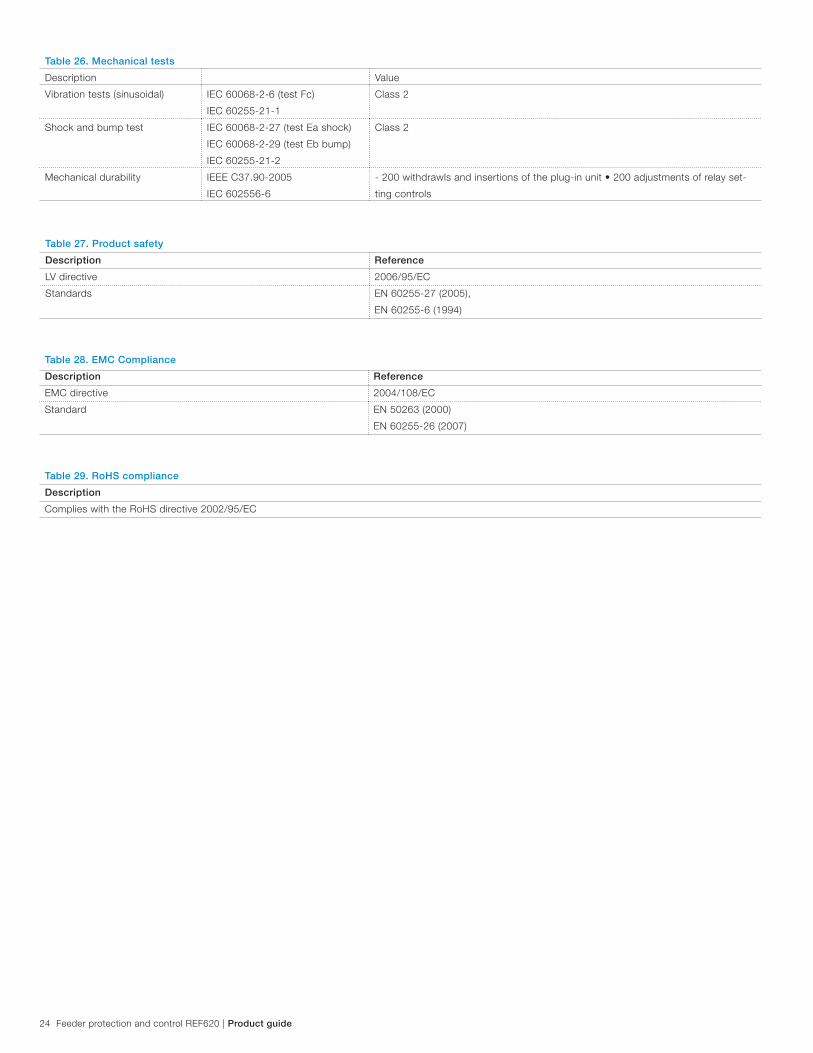
Table 27. Product safety
Description Reference
LV directive 2006/95/EC
Standards EN 60255-27 (2005),
EN 60255-6 (1994)
Table 26. Mechanical tests
Description Value
Vibration tests (sinusoidal) IEC 60068-2-6 (test Fc)
IEC 60255-21-1
Class 2
Shock and bump test IEC 60068-2-27 (test Ea shock)
IEC 60068-2-29 (test Eb bump)
IEC 60255-21-2
Class 2
Mechanical durability IEEE C37.90-2005
IEC 602556-6
- 200 withdrawls and insertions of the plug-in unit • 200 adjustments of relay set-
ting controls
Table 28. EMC Compliance
Description Reference
EMC directive 2004/108/EC
Standard EN 50263 (2000)
EN 60255-26 (2007)
Table 29. RoHS compliance
Description
Complies with the RoHS directive 2002/95/EC

Product guide | Feeder protection and control REF620 25
Table 30. Three-phase non-directional overcurrent protection (50P, 51P)
Characteristic Value
Pickup accuracy 51P
Depending on the frequency of the current measured: fn ±2Hz
±1.5% of the set value or ±0.002 x In
50P-1, 50P-2
and
50P-3
±1.5% of set value or ±0.002 x In
(at currents in the range of 0.1…10 x In)
±5.0% of the set value
(at currents in the range of 10…40 x In)
Pickup time 1) 2)
Minimum Typical Maximum
50P-3:
IFault
= 2 x set Pickup value
IFault
= 10 x set Pickup value
15 ms
12 ms
16 ms
13 ms
17 ms
14 ms
50P-1, 50P-2 and 51P:
IFault
= 2 x set Pickup value
23 ms 25 ms 28 ms
Reset time < 40 ms
Reset ratio Typical 0.96
Retardation time < 30 ms
Trip time accuracy in definite time mode ±1.0% of the set value or ±20 ms
Trip time accuracy in inverse time mode ±5.0% of the theoretical value or ±20 ms 3)
Suppression of harmonics RMS: No suppression
DFT: -50dB at f =
n x fn, where n = 2, 3, 4, 5,…
Peak-to-Peak: No suppression
P-to-P+backup: No suppression
Protection functions
1) Set Operate delay time = 0,02 s, Operate curve type = ANSI defi nite time, Measurement mode = default (depends on stage), current before fault = 0.0 x In, fn = 50 Hz, fault current in
one phase with nominal frequency injected from random phase angle, results based on statistical distribution of 1000 measurements2) Includes the delay of the signal output contact3) Maximum Pickup value = 2.5 x I
, Pickup value multiples in range of 1.5 to 20

26 Feeder protection and control REF620 | Product guide
Table 31. Three-phase non-directional overcurrent protection (50P, 51P) main settings
Parameter Function Value (Range) Step
Pickup value 51P 0.05...5.00 x In
0.01
50P-1, 50P-2 0.10...40.00 x In
0.01
50P-3 1.00...40.00 x In
0.01
Time multiplier 51P 0.05...15.0 0.05
50P-1, 50P-2 0.05...15.00 0.05
Definite time delay 51P 40...200000 ms 10
50P-1, 50P-2 40...200000 ms 10
50P-3 20...200000 ms 10
Operating curve type 1) 51P Definite or inverse time
Curve type: 1, 2, 3, 4, 5, 6, 7, 8, 9, 10, 11, 12, 13, 14,
15, 17, 18, 19
50P-1, 50P-2 Definite or inverse time
Curve type: 1, 3, 5, 9, 10, 12, 15, 17
50P-3 Definite time1) For further reference please refer to the Operating characteristics table at the end of the Technical data chapter
Table 32. Three-phase directional overcurrent protection (67/51P, 67/50P)
Characteristic Value
Pickup accuracy
Depending on the frequency of the current/voltage measured: fn ±2Hz
67/51P
Current:
±1.5% of the set value or ±0.002 x In
Voltage:
±1.5% of the set value or ±0.002 x Vn
Phase angle: ±2°
67/50P-1, 67/50P-2
Current:
±1.5% of set value or ±0.002 x In
(at currents in the range of 0.1…10 x In)
±5.0% of set value
(at currents in the range of 10…40 x In)
Voltage:
±1.5% of the set value or ±0.002 x Vn
Phase angle:
±2°
Pickup time 1) 2) Minimum Typical Maximum
IFault
= 2.0 x set Pickup value 38 ms 43 ms 46 ms
Reset time < 40 ms
Reset ratio Typical 0.96
Retardation time < 35 ms
Trip time accuracy in definite time mode ±1.0% of the set value or ±20 ms
Trip time accuracy in inverse time mode ±5.0% of the theoretical value or ±20 ms 3)
Suppression of harmonics DFT: -50dB at f = n x fn,
where n = 2, 3, 4, 5,…
1) Measurement mode and Pol quantity = default, current before fault = 0.0 x In, voltage before fault 1.0 x U
n, f
n = 50 Hz, fault current in one phase with nominal frequency injected from
random phase angle, results based on statistical distribution of 1000 measurements
2) Includes the delay of the signal output contact
3) Maximum Pickup value = 2.5 x In, Pickup value multiples in range of 1.5 to 20

Product guide | Feeder protection and control REF620 27
Table 33. Three-phase directional overcurrent protection (67/51P, 67/50P) main settings
Parameter Function Value (Range) Step
Pickup value 67/51P 0.05...5.00 x In
0.01
67/50P-1, 67/50P-2 0.10...40.00 x In
0.01
Time multiplier 67/51P, 67/50P-1, 67/50P-2 0.05...15.00 0.05
Definite time delay 67/51P, 67/50P-1, 67/50P-2 40...200000 ms 10
Directional mode 67/51P, 67/50P-1, 67/50P-2 1 = Non-directional
2 = Forward
3 = Reverse
Characteristic angle 67/51P, 67/50P-1, 67/50P-2 -179...180 degrees 1
Operating curve type 1) 67/51P Definite or inverse time
Curve type: 1, 2, 3, 4, 5, 6, 7, 8, 9, 10, 11, 12, 13, 14, 15, 17, 18, 19
67/50P-1, 67/50P-2 Definite or inverse time
Curve type: 1, 3, 5, 9, 10, 12, 15, 17
1) For further reference please refer to the Operating characteristics table at the end of the Technical data chapter
Table 34. Non-directional ground fault protection (51N, 51G, 50N, 50G, SEF)
Characteristic Value
Pickup
accuracy
Depending on the frequency of the current measured: fn ±2Hz
51N, 51G, SEF ±1.5% of the set value or ±0.002 x In
50N-1, 50N-2, 50G-1, 50G-2
and
50N-3, 50G-3
±1.5% of set value or ±0.002 x In
(at currents in the range of 0.1…10 x In)
±5.0% of the set value
(at currents in the range of 10…40 x In)
Pickup time 1) 2) Minimum Typical Maximum
50N-3, 50G-3:
IFault
= 2 x set Pickup value
IFault
= 10 x set Pickup value
15 ms
12 ms
16 ms
13 ms
17 ms
14 ms
50N-1, 50N-2, 50G-1, 50G-2 and
51N, 51G, SEF:
IFault
= 2 x set Pickup value
23 ms 25 ms 28 ms
Reset time < 40 ms
Reset ratio Typical 0.96
Retardation time < 30 ms
Trip time accuracy in definite time mode ±1.0% of the set value or ±20 ms
Trip time accuracy in inverse time mode ±5.0% of the theoretical value or ±20 ms 3)
Suppression of harmonics RMS: No suppression
DFT: -50dB at f =
n x fn, where n = 2, 3, 4, 5,…
Peak-to-Peak: No suppression
1) Measurement mode = default (depends on stage), current before fault = 0.0 x In, fn = 50 Hz, earth-fault current with nominal frequency injected from random phase angle, results based
on statistical distribution of 1000 measurements2) Includes the delay of the signal output contact3) Maximum Pickup value = 2.5 x In, Pickup value multiples in range of 1.5 to 20

28 Feeder protection and control REF620 | Product guide
Table 35. Non-directional ground fault protection (51N, 51G, 50N, 50G) main settings
Parameter Function Value (Range) Step
Pickup value 51N/51G 0.010...5.000 x In
0.005
50N-1, 50N-2, 50G-1, 50G-2 0.10...40.00 x In
0.01
50N-3, 50G-3 1.00...40.00 x In
0.01
Time multiplier 51N/51G 0.05...15.00 0.05
50N-1, 50N-2, 50G-1, 50G-2 0.05...15.00 0.05
Definite time delay 51N/51G 40...200000 ms 10
50N-1, 50N-2, 50G-1, 50G-2 40...200000 ms 10
50N-3, 50G-3 20...200000 ms 10
Operating curve type 1) 51N/51G Definite or inverse time
Curve type: 1, 2, 3, 4, 5, 6, 7, 8, 9, 10, 11, 12, 13, 14, 15, 17, 18, 19
50N-1, 50N-2, 50G-1, 50G-2 Definite or inverse time
Curve type: 1, 3, 5, 9, 10, 12, 15, 17
50N-3, 50G-3 Definite time
1) For further reference please refer to the Operating characteristics table at the end of the Technical data chapter
Table 36. Directional ground fault protection (67/51N, 67/50N)
Characteristic Value
Pickup
accuracy
Depending on the frequency of the current measured: fn ±2Hz
67/51N Current:
±1.5% of the set value or ±0.002 x In
Voltage:
±1.5% of the set value or ±0.002 x Vn
Phase angle:
±2°
67/50N-1, 67/50N-2 Current:
±2% of the set value or ±0.003 x In
(at currents in the range of 0.1…10 x In)
±5.0% of the set value
(at currents in the range of 10…40 x In)
Voltage:
±1.5% of the set value or ±0.01 x Vn
Phase angle: ±2°
Pickup time 1) 2) Minimum Typical Maximum
67/50N-1, 67/50N-2:
IFault
= 2 x set Pickup value 42 ms 45 ms 49 ms
67/51N-1:
IFault
= 2 x set Pickup value 62 ms 65 ms 69 ms
Reset time < 40 ms
Reset ratio Typical 0.96
Retardation time < 30 ms
Trip time accuracy in definite time mode ±1.0% of the set value or ±20 ms
Trip time accuracy in inverse time mode ±5.0% of the theoretical value or ±20 ms 3)
Suppression of harmonics RMS: No suppression
DFT: -50dB at f =
n x fn, where n = 2, 3, 4, 5,…
Peak-to-Peak: No suppression
1) Set Defi nite time delay = 0,06 s, Inverse-time (IDMT) and defi nite-time (DT) curves = ANSI defi nite time, Measurement mode = default (depends on stage), current before fault = 0.0 x In,
fn = 50 Hz, earth-fault current with nominal frequency injected from random phase angle, results based on statistical distribution of 1000 measurements
2) Includes the delay of the signal output contact3) Maximum Pickup value = 2.5 x I
n, Pickup value multiples in range of 1.5 to 20

Product guide | Feeder protection and control REF620 29
Table 37. Directional ground fault protection (67/51N, 67/50N) main settings
Parameter Function Value (Range) Step
Pickup value 67/51N 0.010...5.000 x In 0.005
67/50N-1, 67/50N-2 0.10...40.00 x In 0.01
Directional mode 67/51N, 67N/ 50N-1 and
67/50N-2
1=Non-directional
2=Forward
3=Reverse
Time multiplier 67/51N 0.05...15.00 0.05
67/50N-1, 67/50N-2 0.05...15.00 0.05
Definite time delay 67/51N 60...200000 ms 10
67/50N-1, 67/50N-2 60...200000 ms 10
Operating curve type 1) 67/51N Definite or inverse time
Curve type: 1, 2, 3, 4, 5, 6, 7, 8, 9, 10, 11, 12, 13, 14, 15, 17, 18, 19
67/50N-1, 67/50N-2 Definite or inverse time
Curve type: 1, 3, 5, 15, 17
Operation mode 67/51N, 67/50N-1
and
67/50N-2
1=Phase angle
2=I0Sin
3=I0Cos
4=Phase angle 80
5=Phase angle 88
Table 38. Three-phase non-directional long time overcurrent protection (51LT)
Characteristic Value
Pickup
accuracy
51LT Depending on the frequency of the current measured: fn ±2Hz
±1.5% of the set value or ±0.002 x In
Pickup time 1) 2) 51LT:
IFault = 2 x set Pickup value
Minimum Typical Maximum
23 ms 25 ms 28 ms
Reset time < 40 ms
Reset ratio Typical 0.96
Retardation time < 30 ms
Trip time accuracy in definite time mode ±1.0% of the set value or ±20 ms
Trip time accuracy in inverse time mode ±5.0% of the theoretical value or ±20 ms 4)
Suppression of harmonics RMS: No suppression DFT: -50dB at f =
n x fn, where n = 2, 3, 4, 5,…
Peak-to-Peak: No suppression
P-to-P+backup: No suppression
1) Set Operate delay time = 0.02 s, Operate curve type = ANSI defi nite time, Measurement mode = default (depends on element), current before fault = 0.0 x In, fn = 60 Hz, fault current in
one phase with nominal frequency injected from random phase angle, results based on statistical distribution of 1000 measurements2) Includes the delay of the signal output contact3) Includes the delay of the heavy-duty output contact4) Maximum Pickup value = 2.5 x In, Pickup value multiples in range of 1.5 to 20
1 Embedded 10x factor in time multiplier to achieve ‘very long-time’ curve characteristic
Table 39. Three-phase non-directional long time overcurrent protection (51LT) main settings
Parameter Function Value (Range) Step
Pickup value 51LT 0.05 - 5.00 x In 0.01
Time multiplier 51LT 0.10...15.001 0.01
Definite time delay 51LT 0.020...200.001 s 0.001
Operating curve type 51LT Definite or inverse-time curve type:
6, 7, 14, 15, 17

30 Feeder protection and control REF620 | Product guide
Table 40. Three-phase overvoltage protection (59)
Characteristic Value
Pickup
accuracy
Depending on the frequency of the voltage measured: fn ±2Hz
±1.5% of the set value or ±0.002 x Vn
Pickup time 1) 2) VFault = 1.1 x set Pickup value Minimum Typical Maximum
23 ms 27 ms 30 ms
Reset time < 40 ms
Reset ratio Depends on the Relative hysteresis
Retardation time < 35 ms
Trip time accuracy in definite time mode ±1.0% of the set value or ±20 ms
Trip time accuracy in inverse time mode ±5.0% of the theoretical value or ±20 ms 3)
Suppression of harmonics DFT: -50dB at f = n x fn,
where n = 2, 3, 4, 5,…
1) Pickup value = 1.0 x Un, Voltage before fault 0.9 x U
n, f
n = 50 Hz, overvoltage in one phase-to-phase with nominal frequence injected from random phase angle, results based on statisti-
cal distribution of 1000 measurements2) Includes the delay of the signal output contact3) Maximum Pickup value = 1.20 x U
n, Pickup value multiples in range of 1.10 to 2.00
Table 41. Three-phase overvoltage protection (59) main settings
Parameter Function Value (Range) Step
Pickup value 59 0.05...1.60 x Vn
0.01
Time multiplier 59 0.05...15.00 0.05
Definite time delay 59 40...300000 ms 10
Operating curve type 1) 59 Definite or inverse time
Curve type: 5, 15, 17, 18, 19, 20
1) For further reference please refer to the Operating characteristics table at the end of the Technical data chapter
Table 42. Three-phase undervoltage protection (27)
Characteristic Value
Pickup
accuracy
Depending on the frequency of the voltage measured: fn ±2Hz
±1.5% of the set value or ±0.002 x Vn
Pickup time 1) 2) VFault = 0.9 x set Pickup value Minimum Typical Maximum
62 ms 66 ms 69 ms
Reset time < 40 ms
Reset ratio Depends on the set Relative hysteresis
Retardation time < 35 ms
Trip time accuracy in definite time mode ±1.0% of the set value or ±20 ms
Trip time accuracy in inverse time mode ±5.0% of the theoretical value or ±20 ms 3)
Suppression of harmonics DFT: -50dB at f = n x fn,
where n = 2, 3, 4, 5,…
1) Pickup value = 1.0 x Un, Voltage before fault 1.1 x U
n, f
n = 50 Hz, undervoltage in one phase-to-phase with nominal frequence injected from random phase angle, results based on
statistical distribution of 1000 measurements2) Includes the delay of the signal output contact3) Minimum Pickup value = 0.50, Pickup value multiples in range of 0.90 to 0.20
Table 43. Three-phase undervoltage protection (27) main settings
Parameter Function Value (Range) Step
Pickup value 27 0.05...1.20 x Vn
0.01
Time multiplier 27 0.05...15.00 0.05
Definite time delay 27 60...300000 ms 10
Operating curve type 1) 27 Definite or inverse time
Curve type: 5, 15, 21, 22, 23
1) For further reference please refer to the Operating characteristics table at the end of the Technical data chapter

Product guide | Feeder protection and control REF620 31
Table 44. Positive sequence undervoltage protection (27PS)
Characteristic Value
Pickup
accuracy
Depending on the frequency of the voltage measured: fn ±2Hz
±1.5% of the set value or ±0.002 x Vn
Pickup time 1) 2) VFault
= 0.99 x set Pickup value Minimum Typical Maximum
52 ms 55 ms 57 ms
VFault
= 0.9 x set Pickup value 44 ms 46 ms 49 ms
Reset time < 40 ms
Reset ratio Depends on the set Relative hysteresis
Retardation time < 35 ms
Trip time accuracy in definite time mode ±1.0% of the set value or ±20 ms
Suppression of harmonics DFT: -50dB at f = n x fn,
where n = 2, 3, 4, 5,…
1) Pickup value = 1.0 x Un, Positive sequence voltage before fault 1.1 x U
n, f
n = 50 Hz, positive sequence undervoltage with nominal frequence injected from random phase angle, results
based on statistical distribution of 1000 measurements2) Includes the delay of the signal output contact
Table 45. Positive sequence undervoltage protection (27PS) main settings
Parameter Function Value (Range) Step
Pickup value 27PS 0.010...1.200 x Vn
0.001
Definite time delay 27PS 40...120000 ms 10
Voltage block value 27PS 0.01...1.0 x Vn 0.01
Table 46. Negative sequence overvoltage protection (47)
Characteristic Value
Pickup
accuracy
Depending on the frequency of the voltage measured: fn ±2Hz
±1.5% of the set value or ±0.002 x Vn
Pickup time 1) 2) Minimum Typical Maximum
VFault = 1.1 x set Pickup value 33 ms 35 ms 38 ms
VFault = 2.0 x set Pickup value 25 ms 27 ms 30 ms
Reset time < 40 ms
Reset ratio Typical 0.96
Retardation time < 35 ms
Trip time accuracy in definite time mode ±1.0% of the set value or ±20 ms
Suppression of harmonics
DFT: -50dB at f = n x fn,
where n = 2, 3, 4, 5,…
1) Negative sequence voltage before fault 0.0 x Un, f
n = 50 Hz, negative sequence overvoltage with nominal frequence injected from random phase angle, results based on statistical
distribution of 1000 measurements2) Includes the delay of the signal output contact
Table 47. Negative sequence overvoltage protection (47) main settings
Parameter Function Value (Range) Step
Pickup value 47 0.010...1.000 x Vn
0.001
Definite time delay 47 40...120000 ms 1

32 Feeder protection and control REF620 | Product guide
Table 48. Ground overvoltage protection (59G)
Characteristic Value
Pickup
accuracy
Depending on the frequency of the voltage measured: fn ±2Hz
±1.5% of the set value or ±0.002 x Vn
Pickup time 1) 2) Minimum Typical Maximum
VFault
= 1.1 x set Pickup value 55 ms 57 ms 60 ms
Reset time < 40 ms
Reset ratio Typical 0.96
Retardation time < 35 ms
Trip time accuracy in definite time mode ±1.0% of the set value or ±20 ms
Suppression of harmonics DFT: -50dB at f = n x fn,
where n = 2, 3, 4, 5,…
1) Residual voltage before fault 0.0 x Un, f
n = 50 Hz, residual voltage with nominal frequency injected from random phase angle, results based on statistical distribution of 1000
measurements2) Includes the delay of the signal output contact
Table 49. Ground overvoltage protection (59G) main settings
Parameter Function Value (Range) Step
Pickup value 59G 0.010...1.000 x Vn
0.001
Definite time delay 59G 40...300000 ms 1
Table 50. Negative sequence overcurrent protection (46)
Characteristic Value
Pickup Accuracy Depending on the frequency of the
current measured: fn = ±2Hz
±1.5% of the set value or ±0.002 x In
Pickup time 1) 2) Minimum Typical Maximum
IFault = 2 x set Pickup value
IFault = 10 x set Pickup value
22 ms
14 ms
25 ms
17 ms
27 ms
19 ms
Reset time < 40 ms
Reset ratio Typical 0.96
Retardation time < 35 ms
Trip time accuracy in definite time mode ±1.0% of the set value or ±20 ms
Trip time accuracy in inverse time mode ±5.0% of the theoretical value or ±20 ms 3)
Suppression of harmonics DFT: -50dB at f = n x fn, where
n = 2, 3, 4, 5,…
1) Negative sequence current before fault = 0.0, fn = 50 Hz, results based on statistical distribution of 1000 measurements2) Includes the delay of the signal output contact3) Maximum Pickup value = 2.5 x In, Pickup value multiples in range of 1.5 to 20
Table 51. Negative sequence overcurrent protection (46) main settings
Parameter Function Value (Range) Step
Pickup value 46 0.01...5.00 x In
0.01
Time multiplier 46 0.05...15.00 0.05
Definite time delay 46 40...200000 ms 10
Operating curve type 1) 46 Definite or inverse time
Curve type: 1, 2, 3, 4, 5, 6, 7, 8, 9, 10, 11, 12, 13, 14, 15, 17, 18, 19
1) For further reference please refer to the Operating characteristics table at the end of the Technical data chapter

Product guide | Feeder protection and control REF620 33
Table 52. Phase discontinuity protection (46PD)
Characteristic Value
Pickup Accuracy Depending on the frequency of the current
measured: fn ±2Hz
±2% of the set value
Pickup time < 70 ms
Reset time < 40 ms
Reset ratio Typical 0.96
Retardation time < 35 ms
Trip time accuracy in definite time mode ±1.0% of the set value or ±20 ms
Suppression of harmonics DFT: -50dB at f = n x fn, where n = 2, 3, 4, 5,…
Table 53. Phase discontinuity protection (46PD) main settings
Parameter Function Value (Range) Step
Pickup value
(Current ratio setting I2/I
1)
46PD 10...100 % 1
Definite time delay 46PD 100...30000 ms 1
Min phase current 46PD 0.05...0.30 x In 0.01
Table 54. Circuit breaker failure protection (50BF, 50NBF, 50GBF)
Characteristic Value
Pickup Accuracy Depending on the frequency of the current
measured: fn ±2Hz
±1.5% of the set value or ±0.002 x In
Trip time accuracy ±1.0% of the set value or ±20 ms
Table 55. Circuit breaker failure protection (50BF, 50NBF, 50GBF) main settings
Parameter Function Value (Range) Step
Current value
(Operating phase current)
50BF, 50NBF, 50GBF 0.05...1.00 x In 0.05
Current value Res
(Operating residual current)
50BF, 50NBF, 50GBF 0.05...1.00 x In 0.05
CB failure mode
(Operating mode of function)
50BF, 50NBF, 50GBF 1=Current
2=Breaker status
3=Both
CB fail trip mode 50BF, 50NBF, 50GBF 1=Off
2=Without check
3=Current check
Retrip time 50BF, 50NBF, 50GBF 0...60000 ms 10
CB failure delay 50BF, 50NBF, 50GBF 0...60000 ms 10
CB fault delay 50BF, 50NBF, 50GBF 0...60000 ms 10
Table 56. Three-phase thermal overload (49F)
Characteristic Value
Pickup Accuracy Depending on the frequency of the current
measured: fn ±2Hz
Current measurement: ±0.5% or ±0.002 x In
(at currents in the range of 0.01…4.00 x In)
Trip time accuracy ±2.0% or ±0.50 s

34 Feeder protection and control REF620 | Product guide
Table 57. Three-phase thermal overload (49F) main settings
Parameter Function Value (Range) Step
Env temperature Set
(Ambient temperature used when the
AmbSens is set to Off)
49F -50...100°C 1
Current multiplier
(Current multiplier when function is
used for parallel lines)
49F 1...5 1
Current reference 49F 0.05...4.00 x In
0.01
Temperature rise
(End temperature rise above
ambient)
49F 0.0...200.0°C 0.1
Time constant
(Time constant of the line in
seconds)
49F 60...60000 s 1
Maximum temperature
(temperature level for trip)
49F 20.0...200.0°C 0.1
Alarm value
(Temperature level for start (alarm))
49F 20.0...150.0°C 0.1
Reclose temperature
(Temperature for reset of block
reclose after trip)
49F 20.0...150.0°C 0.1
Initial temperature
(Temperature raise above ambient
temperature at startup)
49F -50.0...100.0 °C 0.1
Table 58. Three-phase inrush current detection (INR)
Characteristic Value
Pickup Accuracy At the frequency f=fn
Current measurement:
±1.5% of set value or ±0.002 x In
Ratio I2f/I1f measurement: ±5.0% of set value
Reset time +35 ms / -0 ms
Reset ratio Typical 0.96
Trip time accuracy +20 ms / -10 ms
Table. 58. Three-phase inrush current detection (INR) main settings
Parameter Function Value (Range) Step
Pickup value
(Ratio of the 2nd to the 1st harmonic
leading to restraint)
INR 5...100 % 1
Definite time delay INR 20...60000 ms 1

Product guide | Feeder protection and control REF620 35
Table 59. Arc protection (AFD)
Characteristic Value
Pickup Accuracy ±3% of the set value or ±0.01 x In
Trip time
Minimum Typical Maximum
Operation mode =
“Light+current” 1) 2)
9 ms 12 ms 15 ms
Operation mode = “Light
only” 2) 9 ms 10 ms 12 ms
Reset time < 40 ms
Reset ratio Typical 0.96
1) Phase Pickup value = 1.0 x In, current before fault = 2.0 x set Phase Pickup value, fn = 50Hz, fault with nominal frequency, results based on statistical distribution 200 measurements2) Includes the delay of the heavy-duty output contact
Table 60. Arc protection (AFD) main settings
Parameter Function Value (Range) Step
Phase Pickup value
(Operating phase current)
AFD 0.50...40.00 x In
0.01
Ground Pickup value
(Operating residual current)
AFD 0.05...8.00 x In
0.01
Operation mode AFD 1=Light+current
2=Light only
3=BI controlled
Table 61. Operating characteristics
Parameter Values (Range)
Inverse-time and definite-time curve types (overcurrent protection) 1=ANSI Ext. inv.
2=ANSI Very. inv.
3=ANSI Norm. inv.
4=ANSI Mod inv.
5=ANSI Def. Time
6=L.T.E. inv.
7=L.T.V. inv.
8=L.T. inv.
9=IEC Norm. inv.
10=IEC Very inv.
11=IEC inv.
12=IEC Ext. inv.
13=IEC S.T. inv.
14=IEC L.T. inv
15=IEC Def. Time
17=Programmable
18=RI type
19=RD type
Inverse-time and definite-time curve types (voltage protection) 5=ANSI Def. Time
15=IEC Def. Time
17=Inv. Curve A
18=Inv. Curve B
19=Inv. Curve C
20=Programmable
21=Inv. Curve A
22=Inv. Curve B
23=Programmable

36 Feeder protection and control REF620 | Product guide
Table 62. Restricted earth fault, low impedance (REF)
Characteristic Value
Pickup
accuracy
Depending on the frequency of the voltage measured: fn ±2Hz
±2.5% of the set value or ±0.002 x In
Pickup time 1) 2) Minimum Typical Maximum
IFault = 2.0 x set Trip value 37 ms 40ms 45 ms
Reset time < 40 ms
Reset ratio Typical 0.96
Retardation time < 35 ms
Trip time accuracy in definite time mode ±1.0% of the set value or ±20 ms
Suppression of harmonics DFT: -50dB at f = n x fn,
where n = 2, 3, 4, 5,…
1) Pickup value = 1.0 x Un, Voltage before fault 0.9 x U
n, f
n = 50 Hz, overvoltage in one phase-to-phase with nominal frequence injected from random phase angle, results based on statis-
tical distribution of 1000 measurements2) Includes the delay of the signal output contact3) Maximum Pickup value = 1.20 x U
n, Pickup value multiples in range of 1.10 to 2.00
Table 63. Restricted earth fault, low impedance (REF) main settings
Parameter Function Value (Range) Step
Trip value REF 5...50 % 1
Restraint mode REF None
2nd harmonic
-
Pickup value 2.H REF 10...50 % 1
Minimum trip time REF 40...300000 ms 1
Operation REF Off
On
Table 65. Single-phase undercurrent protection (37) main settings
Parameter Function Value (Range) Step
Pickup value 37 0.01...1.00 x In
0.01
Current block value 37 0.01...0.50 x In
0.01
Definite time delay 37 400...600000 ms 10
Operation 37 Off
On
Table 64. Single-phase undercurrent protection (37)
Characteristic Value
Pickup Accuracy Depending on the frequency of the current
measured: fn ±2Hz
±1.5% of the set value or ±0.002 x In
Pickup time Typical < 55 ms
Reset time < 40 ms
Reset ratio Typical 1.04
Retardation time < 35 ms
Trip time accuracy in definite time mode ±1.0% of the set value or ±20 ms

Product guide | Feeder protection and control REF620 37
Table 66. Autoreclose (79)
Characteristic Value
Reclose accuracy ±1.0% of the set value or ±20 ms
Table 67. Autoreclose (79) main settings
Parameter Function Value (Range) Step
Reset time 79 0.10...1800.000 s 0.001
Reclose attempts 79 0...7 1
Reclose time 79 0.000...300.00 s 0.001
Enable/disable protection 79 Programmable per reclose attempt
Table 68. Overexcitation protection (24)
Characteristic Value
Pickup accuracy + 3.0% of the set value
Pickup time 1), 2) Frequency change:
Typical 200 ms
Voltage change:
Typical < 40 ms
Reset time < 50 ms
Reset ratio Typical 0.96
Retardation time < 35 ms
Trip time accuracy in definite-time mode ± 1.0% of the set value or + 20 ms
Trip time accuracy in inverse-time mode ± 5.0% of the theoretical value or + 50 ms
1) Results based on statistical distribution of 1000 measurements2) Includes the delay of the signal output contact
Table 69. Overexcitation protection (24) main settings
Parameter Function Value (Range) Step
Pickup value 24 100...200% 1
Curve type 24 Definite-time or Inverse-time curves -
Time multiplier 24 0.1...100 .0 0.1
Trip delay time 24 200...200000 ms 10
Table 70. Frequency protection (81)
Characteristic Value
Pickup accuracy 81O/81U ±10 mHz
df/dt ±100 mHz/s (in range |df/dt| < 5 Hz/s)
± 2.0% of the set value (in range 5 Hz/s < |df/dt| < 15 Hz/s)
Pickup time 81O/81U < 80 ms
df/dt < 120 ms
Reset time < 150 ms
Trip time accuracy ±1.0% of the set value or ±30 ms

38 Feeder protection and control REF620 | Product guide
Table 71. Frequency protection (81) main settings
Parameter Function Value (range) Step
Operation mode 81 1=81U
2=81O
3=df/dt
4=81U + df/dt
5=81O + df/dt
6=81U or df/dt
7=81O or df/dt
Pickup value 81O 81 0.900...1.200 x Fn
0.001
Pickup value 81U 81 0.800...1.100 x Fn
0.001
Pickup value df/dt 81 -0.200...0.200 x Fn /s 0.005
Trip time 81O/81U 81 80...200000 ms 10
Trip time df/dt 81 120...200000 ms 10
Table 72. Thermal overload protection, two time constants (T2PTTR)
Characteristic Value
Pickup accuracy Depending on the frequency of the current measured: fn ±2 Hz
Current measurement: ±1.5% of the set value or ±0.002 x In (at currents in
the range of 0.01...4.00 x In)
Trip time accuracy ±2.0% of the theoretical value or ±0.50 s
Table 73. Load shed and restoration (81LSH)
Characteristic Value
Pickup accuracy 81U ±10 mHz
df/dt ±100 mHz/s (in range |df/ dt| < 5 Hz/s)
± 2.0% of the set value (in range 5 Hz/s < |df/dt| < 15 Hz/s)
Start time 81U < 80 ms
df/dt < 120 ms
Reset time < 150 ms
Trip time accuracy ±1.0% of the set value or ±30 ms
Table 74. Load shed and restoration (81LSH) main settings
Parameter Function Value (Range) Step
Load shed mode 81LSH Freq<
Freq< AND df/dt
Freq< OR df/dt
-
Restore mode 81LSH Disabled
Auto
Manual
-
Pickup value 81U 81LSH 0.800...1.200 x Fn 0.001
Pickup value df/dt 81LSH -0.200...-0.005 x Fn 0.005
Trip time 81U 81LSH 80...200000 ms 10
Trip time df/dt 81LSH 120...200000 ms 10
Restore pickup value 81LSH 0.800...1.200 x Fn 0.001
Restore delay time 81LSH 80...200000 ms 10

Product guide | Feeder protection and control REF620 39
Table 75. Synchronism check (25)
Characteristic Value
Pickup accuracy Depending on the frequency of the voltage
measured: fn ±1 Hz
Voltage: ±3.0% of the set value or ±0.01 x Vn
Frequency: ±10 mHz
Phase angle: ±3°
Reset time < 50 ms
Reset ratio Typical 0.96
Trip time accuracy in definite time mode ±1.0% of the set value or ±20 ms
Table 76. Synchronism check (25) main settings
Parameter Function Value (Range) Description
Live dead
mode
25 -1=Off
1=Both Dead
2=Live L, Dead B
3=Dead L, Live B
4=Dead Bus, L Any
5=Dead L, Bus Any
6=One Live, Dead
7=Not Both Live
Energizing check mode
Difference voltage 25 0.01...0.50 xUn Maximum voltage difference limit
Difference frequency 25 0.001...0.100 xFn Maximum frequency difference limit
Difference angle 25 5...90 deg Maximum angle difference limit
Synchrocheck mode 25 1=Off
2=Synchronous
3=Asynchronous
Synchrocheck operation mode
Control mode 25 1=Continuous
2=Command
Selection of the synchrocheck command or continuous control mode
Dead line value 25 0.1...0.8 xUn Voltage low limit line for energizing check
Live line value 25 0.2...1.0 xUn Voltage high limit line for energizing check
Close pulse 25 200...60000 ms Breaker closing pulse duration
Max energizing V 25 0.50...1.15 xUn Maximum voltage for energizing
Phase shift 25 -180...180 deg Correction of phase difference between measured V_BUS and V_LINE
Minimum Syn time 25 0...60000 ms Minimum time to accept synchronizing
Maximum Syn time 25 100...6000000 ms Maximum time to accept synchronizing
Energizing time 25 100...60000 ms Time delay for energizing check
Closing time of CB 25 40...250 ms Closing time of the breaker

40 Feeder protection and control REF620 | Product guide
Table 77: Phase step distance protection (21P)
Characteristic Value
Pickup accuracy
Depending of the frequency of the current measured: fn ±2Hz
Current: ± 1.5 % of the set value or ± 0.002 x In
Voltage: ±1.5% of the set value or ± 0.002 × Un
Impedance: ±2.0% of the set value or ± 0.1 ohm
Phase angle: ±2°
Pickup time 1)2) Typical 23 ms
Reset time < 40 ms
Reset ratio Typical 0.96
Trip time accuracy in definite time mode ±1.0% of the set value or ±20 ms
Suppression of harmonics DFT: -50dB at f = n x fn, where n = 2, 3, 4, 5,…
Table 78: Phase step distance protection (21P) main settings
Parameter Function Values (Range) Step
Mho polarization method for zones
21P
Pos. seq. volt.
Cross pol
Voltage memory time 21P 0...3000 ms 10
Phase current pickup value, PSL 21P 0.10...10.00 x In 0.01
Enable Load Discrimination, PSL
21P
False
True
Voltage limit for enabling load descri-
mination, PSL 21P
x Un 0.1
Resistive reach for load discrimina-
tion, PSL 21P
0.10...1000.00 ohm 0.01
Load discrimination angle, PSL 21P 5.0...45.0 deg 0.1
Operation Disable/Enable, Zone 1
21P
Enable
Disable
Directional mode, zone Z1
21P
Forward
Reverse
Positive sequence zone reach, Zone
Z1 21P
0.10...1000.00 ohm 0.01
Positive sequence line angle, Zone
Z1 21P
10.0...90.0 deg 0.1
Time delay to trip of PP/3P-loops,
Zone Z1 21P
30...200000 ms 10
Enable optional phase sequence su-
pervision for PP/3P-loops, Zone Z1 21P
False
True
Minimum Pos. seq. current for 3P-
loop, Zone 1 21P
0.10...10.00 x In 0.01
Minimum Neg. seq. current for PP-
loop, Zone 1 21P
0.10...10.00 x In 0.01
21P

Product guide | Feeder protection and control REF620 41
Measurement functions
Table 79. Three-phase current measurements (IA, IB, IC)
Characteristic Value
Measurement accuracy Depending on the frequency of the current measured: fn ±2Hz at currents in the range of 0.01...40 x In
Current: + 0.5% or + 0.002 x In
Phase angle: ± 2.5°
Suppression of harmonics DFT: -50dB at f = n x fn, where n = 2, 3, 4, 5,…
RMS: No suppression
Table 80. Current sequence components (I1, I2, I0)
Characteristic Value
Measurement accuracy Depending on the frequency of the current measured: f/fn = ±2Hz
±1.0% or ±0.002 x In
at currents in the range of 0.01...4.00 x In
Suppression of harmonics DFT: -50dB at f = n x fn, where n = 2, 3, 4, 5,…
Table 81. Three-phase voltage measurements (VA, VB, VC)
Characteristic Value
Measurement accuracy Depending on the frequency of the voltage measured: fn ±2Hz
(at voltages in range 0.01...1.15 x Vn)
Voltage: ± 0.5% or + 0.002 x Vn
Phase angle: ± 2.5°
Suppression of harmonics DFT: -50dB at f = n x fn, where n = 2, 3, 4, 5,…
RMS: No suppression
Table 82. Voltage sequence components (V1, V2, V0)
Characteristic Value
Measurement accuracy Depending on the frequency of the voltage measured: fn ±2Hz at voltages in the range of 0.01…1.15 x V
n
±1.0% or ±0.002 x Un
Suppression of harmonics DFT: -50dB at f = n x fn, where n = 2, 3, 4, 5,…
Table 83. Ground current measurement (IG)
Characteristic Value
Measurement accuracy Depending on the frequency of the current measured: f/fn = ±2Hz
±0.5% or ±0.002 x In
at currents in the range of 0.01...4.00 x In
Suppression of harmonics DFT: -50dB at f = n x fn, where n = 2, 3, 4, 5,…
RMS: No suppression
Table 84. Ground voltage measurement (VG)
Characteristic Value
Measurement accuracy Depending on the frequency of the current measured: f/fn = ±2Hz
±0.5% or ±0.002 x Vn
Suppression of harmonics DFT: -50dB at f = n x fn, where n = 2, 3, 4, 5,…
RMS: No suppression

42 Feeder protection and control REF620 | Product guide
Table 85. Three-phase and single-phase power and energy (P, SP, E, SE)
Characteristic Value
Measurement accuracy At all three currents in range 0.10…1.20 x In
At all three voltages in range 0.50…1.15 x Vn
At the frequency fn ±1Hz
Active power and energy in range |PF| > 0.71
Reactive power and energy in range |PF| < 0.71
±1.5% for power (S,P and Q)
±0.015 for power factor
±1.5% for energy
Suppression of harmonics DFT: -50dB at f = n x fn, where n = 2, 3, 4, 5,…
Table 86. Frequency measurement (f)
Description Value
RTD inputs Operation accuracy ±10 mHz (in measurement range 35 - 75 Hz)
Table 87. Power quality sag (dip), swell, interruption measurements (PQSS)
Characteristic Value
Pickup accuracy ±1.5% of the set value or ±0.2% of the reference voltage
Reset ratio Typical 0.96 (Swell), 1.04 (Sag (dip), Interruption)
Table 88: Voltage unbalance (PQVUB)
Characteristic Value
Operation accuracy ± 1.5 % of the set value or ± 0.002 x In
Reset ratio Typical 0.96
Table 89: Voltage unbalance (PQVUB) main settings
Parameter Values (Range) Step
Set the operation mode for voltage unbalance calculation "Neg Seq
Zero Seq
Neg to Pos Seq
Zero to Pos Seq
Ph vectors Comp"
Voltage unbalance pickup value 1...100 % 1
Specifies the observation period triggering mode "Single
Periodic
Continuous"
The percent to which percentile value PCT_UNB_VAL is calculated 1...100 % 1
Observation period for unbalance calculation "1 Hour
12 Hours
1 Day
7 Days
User defined"
User defined observation period for statistic calculation 1...168 hours 1
Calendar time for observation period start given as YYYYMMDDhh 2008010100...2076010100 1

Product guide | Feeder protection and control REF620 43
Table 90. Current circuit supervision (CCM)
Characteristic Value
Trip time 1) < 30 ms
1) Including the delay of the output contact
Table 91. Current circuit supervision (CCM) main settings
Parameter Values (Range) Unit Description
Pickup value 0.05...0.20 x In
Minimum trip current differential level
Maximum trip current 1.00...5.00 x In
Block of the function at high phase current
Supervision functions
Table 92. Fuse failure supervision (60)
Characteristic Value
Trip time 1) NPS function:
UFault
= 1.1 x set Neg Seq
voltage Lev
UFault
= 5.0 x set Neg Seq
voltage Lev
< 33 ms
< 18 ms
Delta function:
∆U = 1.1 x set Voltage change rate
∆U = 2.0 x set Voltage change rate
<30 ms
<24 ms
1) Includes the delay of the signal output contact, fn = 50 Hz, fault voltage with nominal frequency injected from random phase angle, results based on statistical distribution of 1000
measurements

44 Feeder protection and control REF620 | Product guide
24. Display
The relay’s local HMI includes a large LCD screen standard. The
large LCD display offers full front-panel user-interface functional-
ity with menu navigation and menu views.
The large display offers increased front-panel usability with less
menu scrolling and improved information overview than with
smaller LCD screens. The large display is well-suited for all relay
installations providing an easy viewing interface.Use the photo
of REF620 here.
25. Local HMI
The IED’s local HMI includes a large LCD screen standard. The
large LCD display offers full front-panel user-interface function-
ality with menu navigation and menu views. The large display
offers increased front-panel usability with less menu scroll-
ing and improved information overview than with smaller LCD
screens. In addition, the large display includes a user configu-
rable single line diagram (SLD) with position indication for the
associated primary equipment. The standard configuration of
the IED displays, apart from the primary equipment position,
the related measuring values. Thus all necessary measurement
can be viewed without scrolling through the IED menu. The SLD
view can also be accessed using the web-browser based user
interface. The default SLD can be modified according to user
requirements using the graphical display editor in PCM600.
The local HMI includes a push button (L/R) for local/ remote
operation of the IED. When the IED is in local mode the IED
can only be operated using the local front panel user inter-
face. When the IED is in remote mode, the IED can execute
commands sent from a remote location. The IED supports the
remote selection of local/remote mode via a binary input. This
feature facilitates, for example, the use of an external switch at
the substation to ensure that all IEDs are in local mode during
maintenance work and that the recloser/circuit breakers cannot
be operated remotely from the network control centre.
The large display is well-suited for all IED’s installations provid-
ing an easy viewing interface.
The IED provides sixteen user configurable push buttons that
are used for easy and quick operations, thus eliminating need
for traditional external control switches. These pushbuttons
are accessible in the IED for making any user defined logic. For
each push button different operation modes such as pulsed,
toggled are available. Each push button includes imbedded LED
and configuration labels template is provided.
By eleven user configurable LEDs, traditional annunciation panel
can be replaced. The indication color, red or green, for each
LED can be selected individually with the PCM 600. Each indi-
cation LED on the IED can be set individually to operate in four
different sequences (based on application): two as follow type
and two as latch type. The light from the LEDs can be steady or
flickering. LED label template is provided to suit your protection
and control scheme.
26. Mounting methods
By means of appropriate mounting accessories the standard
relay case for the 620 series relays can be flush mounted,
semi-fl ush mounted or wall mounted. Further, the relays can be
mounted in any standard 19” instrument cabinet by means of
19” mounting panels available with cut-out for one relay. For the
routine testing purposes, the relay cases can be equipped with
Flexitest (FT) test switches, type FT-1 or FT-19R, which can be
mounted side by side or below the relay cases.
Mounting methods:
− Flush mounting
− Semi-fl ush mounting
− Wall mounting
− Mounting to a 19” equipment frame
− Mounting with Flexitest (FT) test switches to a 19”rack
Panel cut-out for flush mounting:
− Width: 9.76” (248 ± 1 mm)
− Height: 6.38” (162 ± 1 mm)
Fig. 3. Large display standard

Product guide | Feeder protection and control REF620 45
27. Accessories and ordering data
The relay type and serial number label identifies the protection
relay. The label is placed above the HMI on the upper part of the
draw-out unit. An order number label is placed on the side of
the draw-out unit as well as inside the case.
The order number consists of a string of alphanumeric charac-
ters generated from the hardware and software modules of the
relay.
Use the ordering key information below.
1 2 3 4 5 6 7 8 9 10 11 12 13 14 15 16 17 18
Ex: NAFCCBCBNBE1BAN1XF N A F C C B C B N B E 1 B A N 1 X F
Digit Description
1) Product
Series
620 series (Includes case)
2) Standard ANSI
3) Main Appl Feeder protection and control
4) Configura-
tion
A: Advanced distribution feeder protection and control
with single breaker
A
B: Advanced distribution feeder protection and control with
one-and-a-half breakers
B
C: Advanced distribution feeder protection and control with two
or one-and-a-half breakers
C
5-6) Analog
Inputs
3 CT + Ground CT + 5 VT + Reclosing A A
3 CT + SEF/HIZ CT + 5 VT + Reclosing A B
6 CT + 8 VT + Reclosing B A
6 CT + Ground CT + 7 VT + Reclosing C A
6 CT + SEF/HIZ CT + 7 VT + Reclosing C B
7-8) Binary I/O 16 BI + 6 BO + 3 HSO A 1
16 BI + 10 BO A A
24 BI + 10 BO + 3 HSO A 2
24 BI + 14 BO A B
32 BI + 14 BO + 3 HSO A 3
32 BI + 18 BO A C
16 BI + 6 BO + 6 HSO B 1
16 BI + 10 BO + 3 HSO B 2
16 BI + 14 BO B A
24 BI + 10 BO + 6 HSO B 3
24 BI + 14 BO + 3 HSO B 4
24 BI + 18 BO B B
16 BI + 6 BO + 6 HSO C 1
16 BI + 10 BO + 3 HSO C 2
16 BI + 14 BO C A
24 BI + 10 BO + 6 HSO C 3
24 BI + 14 BO + 3 HSO C 4
24 BI + 18 BO C B
9-10) Commu-
nication Ports1)
One port: Ethernet 100FX (LC) N A
One port: Ethernet 10/100BaseT (RJ45) N B
Two/three ports: [Ethernet 100 FX (LC) + RS-485 (1x4-wire or 2x2-wire)] + IRIG-B A A
Two/three ports: [Ethernet 10/100BaseT (RJ45) + RS-485 (1x4-wire or 2x2-wire)] +
IRIG-B
A B
Four ports: [Ethernet 100FX (LC) + 2 * Ethernet 10/100BaseT (RJ45) + serial glass fiber
(ST)]
A K
Four ports: [Ethernet 3 * 10/100BaseT (RJ45) + serial glass fiber (ST)] A L
Three ports: Ethernet 10/100BaseT (RJ45) + configurable RS232/RS485 + [RS485 or
serial glass fiber (ST) ] + IRIG-B
3 3

46 Feeder protection and control REF620 | Product guide
1 2 3 4 5 6 7 8 9 10 11 12 13 14 15 16 17 18
Ex: NAFCCBCBNBE1BAN1XF N A F C C B C B N B E 1 B A N 1 X F
Digit Description
Includes Arc
Flash
Detection
One port: Ethernet 100FX (LC) + Arc Flash Detection N F
One port: Ethernet 10/100BaseT (RJ45) + Arc Flash Detection N G
Two/three ports: [Ethernet 100 FX (LC) + RS-485 (1x4-wire or 2x2-wire)] + IRIG-B + Arc
Flash Detection
F F
Two/three ports: [Ethernet 10/100BaseT (RJ45) + RS-485 (1x4-wire or 2x2-wire)] +
IRIG-B + Arc Flash Detection
F G
Four ports: [Ethernet 100FX (LC) + 2 * Ethernet 10/100BaseT (RJ45) + serial glass fiber
(ST)] + Arc Flash Detection
F K
Four ports: [Ethernet 3 * 10/100BaseT (RJ45) + serial glass fiber (ST)] + Arc Flash
Detection
F L
11) Protocols IEC61850 + DNP3.0 L2 + Modbus E
12) Language English 1
English + Spanish 5
English + Portuguese 8
13) Front
Panel
Large LCD (standard) B
14) Option 1 Power quality A
None N
15) Option 2 None N
16) Power
Supply
48-250 Vdc; 100-240 Vac 1
24-60 Vdc 2
17) SW Version SW Version 2.0 X
18) HW
Version
HW F
* Note: All communication options with RS-485 include IRIG-B connections.
1) SNTP is available for time-sync with all Ethernet options. IRIG-B is available for time-sync with all RS-485 options.
Both SNTP and IRIG-B are available for time-sync when both Ethernet and RS-485 options are available.
2) Version is “F” as product is based on M9.1

Product guide | Feeder protection and control REF620 47
Table 93. Accessories and ordering data.
Item Order Number
Tools
PCM600 user tool PCM600-24
Cables
Cable for optical sensors for arc protection 1.5 m 1MRS120534-1.5
Cable for optical sensors for arc protection 3.0 m 1MRS120534-3.0
Cable for optical sensors for arc protection 5.0 m 1MRS120534-5.0
Mounting accessories
Semi-flush mounting kit 2RCA030573A0001
Wall mounting kit 2RCA030894A0001
19” mounting panel kit 2RCA031135A0001
Protection cover kit 2RCA030963A0001
Test switches
FT-1, FT-14, and FT-19 Flexitest switches See Descriptive bulletins DB 41-077 and DB 41-078 on www.abb.com/substationautomation
Table 94. Tools
Tools
Configuration, setting and SA system tools Version
PCM600 2.4.1 or later
Web-browser based user interface IE 7.0 or later
REF620 Connectivity Package 2.0 ANSI or later
COM600 substation product V3.5 or later
MicroSCADA Pro Substation Automation system 9.3 or later
28. Tools
The relay is delivered as a pre-configured unit. The default pa-
rameter setting values can be changed from the front-panel user
interface, the web-browser based user interface (WHMI) or the
PCM600 tool in combination with the relay specific connectivity
package (CP).
PCM600 offers extensive relay configuration functions such as
application configuration, signal matrix, communication man-
agement, graphical display editor, and IEC 61850 communica-
tion configuration including horizontal relay-to-relay communica-
tion, GOOSE.
When the web-browser based user interface is used, the relay
can be accessed either locally or remotely using a web browser
(IE 6.0 or later). For security reasons, the web-browser based
user interface is disabled by default. The interface can be
enabled with the PCM600 tool or from the front panel user inter-
face. The functionality of the interface can be limited to read-
only access by means of PCM600.

48 Feeder protection and control REF620 | Product guide
29. Terminal diagrams
Figure 4. REF620 connection diagram configuration A
SO2
TCM-2
PO4
SO1
TCM-1
PO3
IG
IA
BI 4
BI 3
BI 2
BI 1
REF620Config A
ABC
S1S2
P1
P2
52-1
BA C
PO2
PO1
IRF
+
-Vaux
IED FAILURE ALARM
LAN 1
V Sync
2)1)
GND (Case)
RX/+RX/-A/+ TX/+B/- TX/-AGND (Isolated Ground )
IRIG-B+IRIG-B- DCD Rx/+
AGNDDTRTxDRxD
1
9876
X6
432
5
Rx/-RTS B/- Tx/-
CTS A/+ Tx/+Optical ST
1)EIA485/IRIG-B
EIA232/485
X1
1
9876
X5
432
5
X12
1)
1)
X130
123
9
456
10
78
1112131415161718
16
151918
10
111213
14
22
23
24
17
21
20
X100
67
89
10
21
3
45
X120123
4
567891011
1213
14
X105
X110
X105 3)
X110 3)
BIO Card Inputs
BIO Card Inputs
3)1)
3)1)
BIO Card Outputs3)1)
3)1)
IB
IC
VA
VB
VC
VG
BI 4
Breaker Close Command
Breaker Fail (50BF) Backup Trip
Breaker Trip Coil -1 & TC Supervision
(86-94-1)
Breaker Trip Coil -2 & TC Supervision
(86-94-2)
52a
52b
B lock AR
BI 1
BI 2
BI 3
Light Sensor Input 1
X13
Light Sensor Input 2
X14
Light Sensor Input 3
X15
BIO Card Outputs
1)
X115 X115 3)BIO Card Inputs
3)1) 3)1)BIO Card Outputs
5)
4)
4)
4)
Notes:1)� � � � � �Order Selectable, Op�onal
2)� � � � � �100BaseFX / LC or 100BaseTX / RJ45
3)� � � � � �Refer next sheets for details of Binary Input and Output cards (BIO)
4)� � � � �Connec�ons shown are applicable with Open Delta (V) (Ph-Ph) connected VTs. Connec�ons and configura�ons with WYE (along with Broken delta) VT connec�ons are suggested in other parts of the applica�on manual
5)� � � � � �IG Input is order selectable, either 5/1A or 1/0.2AWhen IG is ordered with sensi�ve current input (1/0.2A), current source is from CBCT
6) Synchronizing input is shown as Ph-Ph voltage input (Set as Delta in analog input channel configura�on ). Alterna�vely VA (Phase-Neutral) voltage input is possible, to be suitably configured in the IED
8)

Product guide | Feeder protection and control REF620 49
X110
16
14
15
19
17
18
22
20
21
SO3
SO2
SO1
24
23SO4
2)
X11012
BI 6
BI 5
BI 4
BI 3
BI 1
BI 8
BI 7
4 BI 23 2)
X105
16
14
15
19
17
18
22
20
21
SO3
SO2
SO1
24
23SO4
1)
X10512
BI 6
BI 5
BI 4
BI 3
BI 1
BI 8
BI 7
4 BI 23
1)
REF620Config A
56
7
8910
1213
11
56
7
8910
1213
11
X1101
BI 6
BI 5
BI 4
BI 3
BI 1
BI 8
BI 7
BI 22 X11015
16
HSO3
HSO2
HSO1
2)
2)
3
4
6
7
9
8
5
10
Master Trip -1 & Trip from Arc Protection -1
Trip from Arc Protection -2
Trip from Arc Protection -3
3)
1) Order Selectable, Op�onal2) Order Selectable, Op�onal alterna�ves3) Default outputs configured with High Speed Outputs when Arc protec�on op�on is chosen
Alternative Module, Slot ID X110
19
2023
24
Figure 5. REF620 connection diagram configuration A

50 Feeder protection and control REF620 | Product guide
X115
16
14
15
19
17
18
22
20
21
SO3
SO2
SO1
24
23SO4
X11512
BI 6
BI 5
BI 4
BI 3
BI 1
BI 8
BI 7
4 BI 23
1)
1)
REF620Config A
56
7
8910
1213
11
Notes:
1)� � � � � �Order Selectable, Op�onal
Figure 6. REF620 connection diagram config A

Product guide | Feeder protection and control REF620 51
Figure 7. REF620 connection diagram configuration A
IG
IA
REF620Config A
ABC
52
X120
7
89
10111213
14
IB
IC
From HV System
MV Switchgear Bus
S1
S2
P1
P2

52 Feeder protection and control REF620 | Product guide
SO2
TCM-2
PO4
SO1
TCM-1
PO3
IA(1)
REF620Config B
ABC
S1S2
P1
P2
52-1
PO2
PO1
IRF
+
-Vaux
IED FAILURE ALARM
V Sync(1)
X130
78
1112
131415161718
16
151918
10
111213
14
22
23
24
17
21
20
X100
67
89
10
21
3
45
X120
IB(1)
IC(1)
VA(2)
VB(2)
VC(2)
V Sync (2)
Breaker 52-1 Close Command
52-1 Breaker Fail (50BF) Backup Trip
52-1 Breaker Trip & TC Supervision
(86-94-1)
52-2 Breaker Trip & TC Supervision
(86-94-2)
IA(2) 123
45
6
IB(2)
IC(2)
VA(1)
BUS 1
FEEDER 1
S1S2
P1
P2
52-2
FEEDER 2
52-3
ABC
BUS 2
123456
ABC
ABC
4)
4)
X105
X110
X105 3)
X110 3)
BIO Card Inputs
BIO Card Inputs
3)1)
3)1)
BIO Card Outputs3)1)
3)1)BIO Card Outputs
X115 X115 3)BIO Card Inputs
3)1) 3)1)BIO Card Outputs
LAN 1 2)1)X1
Light Sensor Input 1
X13
Light Sensor Input 2
X14
Light Sensor Input 3
X15
1)
GND (Case)
RX/+RX/-A/+ TX/+B/- TX/-AGND (Isolated Ground )
IRIG-B+IRIG-B- DCD Rx/+
AGNDDTRTxDRxD
1
9876
X6
432
5
Rx/-RTS B/- Tx/-
CTS A/+ Tx/+Optical ST
1)EIA485/IRIG-B
EIA232 /4851
9876
X5
432
5
X12
1)
1)
Breaker 52-2 Close Command
52-2 Breaker Fail (50BF) Backup Trip
91011
1213
14
7
8CT(1)
CT(2)
VT(1)
VT(2)
Not Used
Notes:1)� � � � � �Order Selectable, Op�onal
2)� � � � � �100BaseFX / LC or 100BaseTX / RJ45
3)� � � � � �Refer next sheets for details of Binary Input and Output cards (BIO)
4)� � � � �Connec�ons shown are applicable with Open Delta (V) (Ph-Ph) connected VTs . Connec�ons and configura�ons with WYE (along with Broken delta) VT connec�ons are suggested in other parts of the applica�on manual
6) Synchronizing input is shown as Ph-Ph voltage input (Set as Delta in analog input channel configura�on). Alterna�vely VA (Phase-Neutral) voltage input is possible, to be suitably configured in the IED
6)
6)
910
VB(1)
VC(1)
Figure 8. REF620 connection diagram config B

Product guide | Feeder protection and control REF620 53
X110
16
14
15
19
17
18
22
20
21
SO3
SO2
SO1
24
23SO4
1)
X11012
BI 6
BI 5
BI 4
BI 3
BI 1
BI 8
BI 7
4 BI 23
2)
1)
X105
16
14
15
19
17
18
22
20
21
SO3
SO2
SO1
24
23SO4
1)
X10512
BI 6
BI 5
BI 4
BI 3
BI 1
BI 8
BI 7
4 BI 23
1)
REF620Config B
52-2a
52-2b
56
7
8910
1213
11
56
7
8910
1213
11
X1101
BI 6
BI 5
BI 4
BI 3
BI 1
BI 8
BI 7
BI 22 X11015
1619
2023
24
HSO3
HSO2
HSO1
1)
3)
1)
3
4
6
7
9
8
5
10
Alternative Card, Position X110
52-1b
52-1a
Master Trip -1 & Trip from Arc Protection -1
Trip from Arc Protection -2
Trip from Arc Protection -3
3)
1) Order Selectable, Op�onal2) Order Selectable, Op�onal alterna�ves3) Default outputs configured with High Speed Outputs when Arc protec�on op�on is chosen
52-2a
52-2b
52-1b
52-1a
Figure 9. REF620 connection diagram config B

54 Feeder protection and control REF620 | Product guide
X115
16
14
15
19
17
18
22
20
21
SO3
SO2
SO1
24
23SO4
X11512
BI 6
BI 5
BI 4
BI 3
BI 1
BI 8
BI 7
4 BI 23
2)
2)
REF620Config B
56
7
8910
1213
11
X1151
BI 6
BI 5
BI 4
BI 3
BI 1
BI 8
BI 7
BI 22 X115
15
1619
2023
24
HSO3
HSO2
HSO1
2)
2)
3
4
6
7
9
8
5
10
Alternative Card, Position X115
Notes:2)� � � � � �Order Selectable, Op�onal alterna�ves3) High speed BIO card in this slot only when X110 slot is equipped with High speed BIO card
3)
3)
Figure 10. REF620 connection diagram config B

Product guide | Feeder protection and control REF620 55
Figure 11. REF620 connection diagram config C
SO2
TCM-2
PO4
SO1
TCM-1
PO3
IA(1)
REF620Config C
ABC
S1S2
P1
P2
52-1
PO2
PO1
IRF
+
-Vaux
IED FAILURE ALARM
V Sync
X130
78
1112
131415161718
16
151918
10
111213
14
22
23
24
17
21
20
X100
67
89
10
21
3
45
X120
IB(1)
IC(1)
VA(2)
VB(2)
VC(2)
Not Used
Breaker 52-1 Close Command
52-1 Breaker Fail (50BF) Backup Trip
52-1 Breaker Trip & TC Supervision
(86-94-1)
52-2 Breaker Trip & TC Supervision
(86-94-2)
IA(2) 123
45
6
IB(2)
IC(2)
VA(1)
BUS 1
FEEDER 1
S1S2
P1
P2
52-2
ABC
BUS 2
123456
ABC
4)
4)
X105
X110
X105 3)
X110 3)
BIO Card Inputs
BIO Card Inputs
3)1)
3)1)
BIO Card Outputs3)1)
3)1)BIO Card Outputs
X115 X115 3)BIO Card Inputs
3)1) 3)1)BIO Card Outputs
LAN 1 2)1)X1
Light Sensor Input 1
X13
Light Sensor Input 2
X14
Light Sensor Input 3
X15
1)
GND (Case)
RX/+RX/-A/+ TX/+B/- TX/-AGND (Isolated Ground )
IRIG-B+IRIG-B- DCD Rx/+
AGNDDTRTxDRxD
1
9876
X6
432
5
Rx/-RTS B/- Tx/-
CTS A/+ Tx/+Optical ST
1)EIA485 /IRIG-B
EIA232/4851
9876
X5
432
5
X12
1)
1)
Breaker 52-2 Close Command
52-2 Breaker Fail (50BF) Backup Trip
91011
1213
14
7
8CT(1)
CT(2)
VT (1)
VT(2)
IG
Notes:1)� � � � � �Order Selectable, Op�onal2)� � � � � �100BaseFX / LC or 100BaseTX / RJ453)� � � � � �Refer next sheets for details of Binary Input and Output cards (BIO)
4)� � � � �Connec�ons shown are applicable with Open Delta (V) (Ph-Ph) connected VTs. Connec�ons and configura�ons with WYE (along with Broken delta) VT connec�ons are suggested in other parts of the applica�on manual
5) IG Input is order selectable, either 5/1A or 1/0.2A. When IG is ordered with sensi�ve current input (1/0.2A), current source is typically from CBCT
6) Synchronizing input is shown as Ph-Ph voltage input (Set as Delta in analog input channel configura�on as default). Alterna�vely VA (Phase-Neutral) voltage input is possible, to be suitably configured in the IED7) With paralleled CTs, CT neutral Point shall be grounded only at one point in the installa�on
6)
910
VB(1)
VC (1)
5)
7)

56 Feeder protection and control REF620 | Product guide
Figure 12. REF620 connection diagram config C
IA(1)
REF620Config C
ABC
S1S2
P1
P2
52-1
X120
IB(1)
IC(1)
IA(2) 123
45
6
IB(2)
IC(2)
BUS 1
FEEDER 1
S1S2
P1
P2
52-2
ABC
91011
1213
14
7
8CT(1)
CT(2)
IG 5)
A B C

Product guide | Feeder protection and control REF620 57
X110
16
14
15
19
17
18
22
20
21
SO3
SO2
SO1
24
23SO4
1)
X11012
BI 6
BI 5
BI 4
BI 3
BI 1
BI 8
BI 7
4 BI 23
2)
1)
X105
16
14
15
19
17
18
22
20
21
SO3
SO2
SO1
24
23SO4
1)
X10512
BI 6
BI 5
BI 4
BI 3
BI 1
BI 8
BI 7
4 BI 23
1)
REF620Config C
52-2a
52-2b
56
7
8910
1213
11
56
7
8910
1213
11
X1101
BI 6
BI 5
BI 4
BI 3
BI 1
BI 8
BI 7
BI 22 X11015
1619
2023
24
HSO3
HSO2
HSO1
1)
3)
1)
3
4
6
7
9
8
5
10
Alternative Card, Position X110
52-1b
52-1a
Master Trip -1 & Trip from Arc Protection -1
Trip from Arc Protection -2
Trip from Arc Protection -3
3)
1) Order Selectable, Op�onal2) Order Selectable, Op�onal alterna�ves3) Default outputs configured with High Speed Outputs when Arc protec�on op�on is chosen
52-2a
52-2b
52-1b
52-1a
Figure 13. REF620 connection diagram config C

58 Feeder protection and control REF620 | Product guide
Figure 14. REF620 connection diagram config C
X115
16
14
15
19
17
18
22
20
21
SO3
SO2
SO1
24
23SO4
X11512
BI 6
BI 5
BI 4
BI 3
BI 1
BI 8
BI 7
4 BI 23
2)
2)
REF620Config C
56
7
8910
1213
11
X1151
BI 6
BI 5
BI 4
BI 3
BI 1
BI 8
BI 7
BI 22 X115
15
1619
2023
24
HS PO3
HS PO2
HS PO1
2)
2)
3
4
6
7
9
8
5
10
Alternative Card, Position X115
Notes:2)� � � � � �Order Selectable, Op�onal alterna�ves3) High speed BIO card in this slot only when X110 slot is equipped with High speed BIO card
3)
3)

Product guide | Feeder protection and control REF620 59
30. Certificates
The REF620 is a UL Listed product, UL File/Sec. E103204
31. References
The download area on the right hand side of the product web
page contains the latest product documentation, such as
technical manual, installation manual, operator manual,etc. The
selection tool on the web page helps you find the documents by
the document category and language.
The Features and Application tabs contain product related infor-
mation in a compact format.
The www.abb.com/substationautomation portal offers you in-
formation about the distribution automation product and service
range. You will find the latest relevant information on the feeder
protection and control REF620 ANSI on the product web page.
32. Functions, codes and symbols
Table 95. REF620 Functions, codes and symbols
IEC61850 ANSI/C37.2 IEC60617
Protection
Three-phase non-directional overcurrent protection, low stage, instance 1 PHLPTOC1 51P 3I> (1)
Three-phase non-directional overcurrent protection, high stage, instance 1 PHHPTOC1 50P-1 3I>> (1)
Three-phase non-directional overcurrent protection, high stage, instance 2 PHHPTOC2 50P-2 3I>> (2)
Three-phase non-directional overcurrent protection, instantaneous stage, instance 1 PHIPTOC1 50P-3 3I>>> (1)
Three-phase non-directional long time overcurrent protection, low stage, instance 1 PHLTPTOC1 51LT 3I> (3)
Three-phase directional overcurrent protection, low stage, instance 1 DPHLPDOC1 67/51P 3I> -> (1)
Three-phase directional overcurrent protection, high stage, instance 1 DPHHPDOC1 67/50P-1 3I>> -> (1)
Three-phase directional overcurrent protection, high stage, instance 2 DPHHPDOC2 67/50P-2 3I>> -> (2)
Non-directional ground-fault protection, low stage, instance 1 EFLPTOC1 51G Io> (1)
Non-directional ground-fault protection, low stage, instance 2 EFLPTOC2 51N-1 Io> (2)
Non-directional ground-fault protection, low stage, instance 4 EFLPTOC4 50SEF Io> (4)
Non-directional ground-fault protection, high stage, instance 1 EFHPTOC1 50G-1 Io>> (1)
Non-directional ground-fault protection, high stage, instance 2 EFHPTOC2 50G-2 Io>> (2)
Non-directional ground-fault protection, high stage, instance 3 EFHPTOC3 50N-1 Io>> (3)
Non-directional ground-fault protection, high stage, instance 4 EFHPTOC4 50N-2 Io>> (4)
Non-directional ground-fault protection, instantaneous stage, instance 1 EFIPTOC1 50G-3 Io>>> (1)
Non-directional ground-fault protection, instantaneous stage, instance 2 EFIPTOC2 50N-3 Io>>> (2)
Directional ground-fault protection, low stage, instance 1 DEFLPDEF1 67/51N Io> -> (1)
Directional ground-fault protection, high stage, instance 1 DEFHPDEF1 67/50N-1 Io>> -> (1)
Directional ground-fault protection, high stage, instance 2 DEFHPDEF2 67/50N-2 Io>> -> (2)
Three phase directional power protection, instance 1 DPSRDIR1 32P-1 I1-> (1)
Ground directional power protection, instance 1 DNZSRDIR1 32N-1 I2 ->, Io-> (1)
Phase distance protection, instance 1 PHDSTPDIS1 21P Z<
Negative-sequence overcurrent protection, instance 1 NSPTOC1 46-1 I2> (1)
Negative-sequence overcurrent protection, instance 2 NSPTOC2 46-2 I2> (2)
Phase discontinuity protection PDNSPTOC1 46PD I2/I1>
Residual overvoltage protection, instance 1 ROVPTOV1 59G Uo> (1)
Residual overvoltage protection, instance 2 ROVPTOV2 59N-1(1) Uo> (2)
Residual overvoltage protection, instance 3 ROVPTOV3 59N-1(2) Uo> (3)
Three-phase undervoltage protection, instance 1 PHPTUV1 27-1(1) 3U< (1)
Three-phase undervoltage protection, instance 2 PHPTUV2 27-2(1) 3U< (2)
Three-phase undervoltage protection, instance 3 PHPTUV3 27-1(2) 3U< (3)

60 Feeder protection and control REF620 | Product guide
Table 95. REF620 Functions, codes and symbols (continued)
IEC61850 ANSI/C37.2 IEC60617
Protection
Three-phase non-directional overcurrent protection, low stage, instance 1 PHLPTOC1 51P 3I> (1)
Three-phase non-directional overcurrent protection, high stage, instance 1 PHHPTOC1 50P-1 3I>> (1)
Three-phase non-directional overcurrent protection, high stage, instance 2 PHHPTOC2 50P-2 3I>> (2)
Three-phase non-directional overcurrent protection, instantaneous stage, instance 1 PHIPTOC1 50P-3 3I>>> (1)
Three-phase non-directional long time overcurrent protection, low stage, instance 1 PHLTPTOC1 51LT 3I> (3)
Three-phase directional overcurrent protection, low stage, instance 1 DPHLPDOC1 67/51P 3I> -> (1)
Three-phase directional overcurrent protection, high stage, instance 1 DPHHPDOC1 67/50P-1 3I>> -> (1)
Three-phase directional overcurrent protection, high stage, instance 2 DPHHPDOC2 67/50P-2 3I>> -> (2)
Non-directional ground-fault protection, low stage, instance 1 EFLPTOC1 51G Io> (1)
Non-directional ground-fault protection, low stage, instance 2 EFLPTOC2 51N-1 Io> (2)
Non-directional ground-fault protection, low stage, instance 4 EFLPTOC4 50SEF Io> (4)
Non-directional ground-fault protection, high stage, instance 1 EFHPTOC1 50G-1 Io>> (1)
Non-directional ground-fault protection, high stage, instance 2 EFHPTOC2 50G-2 Io>> (2)
Non-directional ground-fault protection, high stage, instance 3 EFHPTOC3 50N-1 Io>> (3)
Non-directional ground-fault protection, high stage, instance 4 EFHPTOC4 50N-2 Io>> (4)
Non-directional ground-fault protection, instantaneous stage, instance 1 EFIPTOC1 50G-3 Io>>> (1)
Non-directional ground-fault protection, instantaneous stage, instance 2 EFIPTOC2 50N-3 Io>>> (2)
Directional ground-fault protection, low stage, instance 1 DEFLPDEF1 67/51N Io> -> (1)
Directional ground-fault protection, high stage, instance 1 DEFHPDEF1 67/50N-1 Io>> -> (1)
Directional ground-fault protection, high stage, instance 2 DEFHPDEF2 67/50N-2 Io>> -> (2)
Three phase directional power protection, instance 1 DPSRDIR1 32P-1 I1-> (1)
Ground directional power protection, instance 1 DNZSRDIR1 32N-1 I2 ->, Io-> (1)
Phase distance protection, instance 1 PHDSTPDIS1 21P Z<
Negative-sequence overcurrent protection, instance 1 NSPTOC1 46-1 I2> (1)
Negative-sequence overcurrent protection, instance 2 NSPTOC2 46-2 I2> (2)
Phase discontinuity protection PDNSPTOC1 46PD I2/I1>
Residual overvoltage protection, instance 1 ROVPTOV1 59G Uo> (1)
Residual overvoltage protection, instance 2 ROVPTOV2 59N-1(1) Uo> (2)
Residual overvoltage protection, instance 3 ROVPTOV3 59N-1(2) Uo> (3)
Three-phase undervoltage protection, instance 1 PHPTUV1 27-1(1) 3U< (1)
Three-phase undervoltage protection, instance 2 PHPTUV2 27-2(1) 3U< (2)
Three-phase undervoltage protection, instance 3 PHPTUV3 27-1(2) 3U< (3)
Three-phase undervoltage protection, instance 4 PHPTUV4 27-2(2) 3U< (4)
Three-phase overvoltage protection, instance 1 PHPTOV1 59-1(1) 3U> (1)
Three-phase overvoltage protection, instance 2 PHPTOV2 59-2(1) 3U> (2)
Three-phase overvoltage protection, instance 3 PHPTOV3 59-1(2) 3U> (3)
Three-phase overvoltage protection, instance 4 PHPTOV4 59-2(2) 3U> (4)
Negative-sequence overvoltage protection, instance 1 NSPTOV1 47-1(1) U2> (1)
Negative-sequence overvoltage protection, instance 2 NSPTOV2 47-2(1) U2> (2)
Negative-sequence overvoltage protection, instance 3 NSPTOV3 47-1(2) U2> (3)
Negative-sequence overvoltage protection, instance 4 NSPTOV4 47-2(2) U2> (4)
Frequency protection, instance 1 FRPFRQ1 81-1 f>/f<,df/dt (1)
Frequency protection, instance 2 FRPFRQ2 81-2 f>/f<,df/dt (2)
Voltage per hertz protection, instance 1 OEPVPH1 24 U/f> (1)
Three-phase thermal protection for feeders, cables and distribution transformers, Instance 1 T1PTTR1 49F 3Ith>F (1)
Phase current sets summing function CMSUM1 CSUM CSUM
Three phase measurement switching VMSWI1 VSWI VSWI
Numerical stabilized low impedance restricted ground-fault protection LREFPNDF1 87LOZREF dIoLo>
Circuit breaker failure protection, instance 1 CCBRBRF1 50BF-1 3I>/Io>BF (1)
Circuit breaker failure protection, instance 2 CCBRBRF2 50BF-2 3I>/Io>BF (2)
Three-phase inrush detector, instance 1 INRPHAR1 INR 3I2f> (1)

Product guide | Feeder protection and control REF620 61
33. Document revision history
Rev. A, V2.0

62 Feeder protection and control REF620 | Product guide
34. Notes

Product guide | Feeder protection and control REF620 63

Contact us
1M
AC
50
66
35
-PG
Rev
B N
ove
mb
er
20
13ABB Inc.
Distribution Automation
4300 Coral Ridge Drive
Coral Springs, Florida 33065
Phone: +1 954 752 6700
Fax: +1 954 345 5329
www.abb.com/substationautomation


![EPOS Business Solutions IMPACT Headset Solutions · [•] Mobile connectivity available via optional BTD 800 dongle accessory [[•]] Option available with additional accessory *](https://img.dokumen.tips/doc/110x75/5f70965b217e654e267c89e9/epos-business-solutions-impact-headset-solutions-a-mobile-connectivity-available.jpg)