Embed Size (px)
Citation preview
209351 REV E ECO 18358 04/06/2017
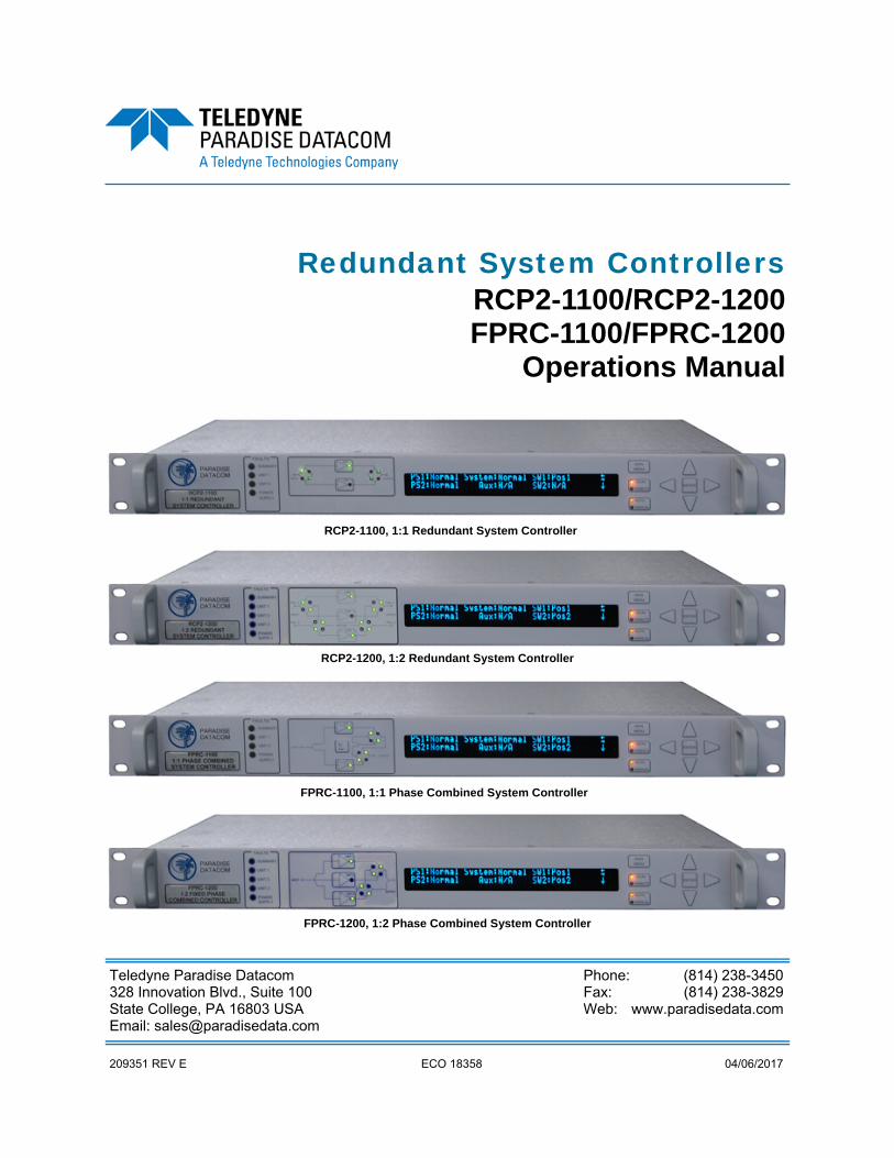
Redundant System Controllers RCP2-1100/RCP2-1200 FPRC-1100/FPRC-1200
Operations Manual
Teledyne Paradise Datacom Phone: (814) 238-3450 328 Innovation Blvd., Suite 100 Fax: (814) 238-3829 State College, PA 16803 USA Web: www.paradisedata.com Email: [email protected]
RCP2-1100, 1:1 Redundant System Controller
FPRC-1100, 1:1 Phase Combined System Controller
FPRC-1200, 1:2 Phase Combined System Controller
RCP2-1200, 1:2 Redundant System Controller

2 209351 REV E Operations Manual, Redundant System Controllers
© 2013-2017 Teledyne Paradise Datacom LLC Printed in the USA
Teledyne Paradise Datacom, a division of Teledyne Wireless LLC, is a single source for high power sol-id state amplifiers (SSPAs), Low Noise Amplifiers (LNAs), Block Up Converters (BUCs), and Modem products. Operating out of two primary locations, Witham, United Kingdom, and State College, PA, USA, Teledyne Paradise Datacom has a more than 20 year history of providing innovative solutions to enable satellite uplinks, battlefield communications, and cellular backhaul. Teledyne Paradise Datacom Teledyne Paradise Datacom Ltd. 328 Innovation Blvd., Suite 100 2&3 The Matchyns, London Road, Rivenhall End State College, PA 16803 USA Witham, Essex CM8 3HA England (814) 238-3450 (switchboard) +44 (0) 1376 515636 (814) 238-3829 (fax) +44 (0) 1376 533764 (fax) Information in this document is subject to change without notice. The latest revision of this document may be downloaded from the company web site: http://www.paradisedata.com. Use and Disclosure of Data The items described herein are controlled by the U.S. Government and authorized for export only to the country of ultimate destination for use by the ultimate consignee or end-user(s) herein identified. They may not be resold, transferred, or otherwise disposed of, to any other country or to any person other than the authorized ultimate consignee or end-user(s), either in their original form or after being incorpo-rated into other items, without first obtaining approval from the U.S. government or as otherwise author-ized by U.S. law and regulations. Proprietary and Confidential The information contained in this document is the sole property of Teledyne Paradise Datacom. Any re-production in part or as a whole without the written permission of Teledyne Paradise Datacom is prohib-ited. All other company names and product names in this document are property of the respective compa-nies.
Operations Manual, Redundant System Controllers 209351 REV E 3
Table of Contents ..................................................................................................................... 3 List of Figures ........................................................................................................................... 8 List of Tables ........................................................................................................................... 10 Section 1: General Information ............................................................................................. 11
1.0 Introduction ............................................................................................................. 11 1.1 Description .............................................................................................................. 11 1.2 Equipment Supplied ................................................................................................ 11 1.3 Specifications .......................................................................................................... 12
1.3.1 Outline Drawings ...................................................................................... 12 1.4 Safety Considerations ............................................................................................. 13
1.4.1 High Voltage Hazards .............................................................................. 13 1.4.2 High Current Hazards .............................................................................. 13 1.4.3 Electrical Discharge Hazards ................................................................... 14
Section 2: Description ............................................................................................................ 15 2.0 Introduction ............................................................................................................. 15 2.1 Inspection ................................................................................................................ 15 2.2 Mounting ................................................................................................................. 15 2.3 Storage and Shipment ............................................................................................ 15 2.4 Prime Power Connection (J1, J2) ........................................................................... 15 2.5 Cable Connections .................................................................................................. 16
2.5.1 Control Cable Connector (J3) - MS3112E16-23S .................................... 16 2.5.2 Serial Port, Main (J4) - DB9 (F) ................................................................ 16 2.5.3 Serial Port, Local (J5) - DB9 (M) .............................................................. 17 2.5.4 Program Port (J6) - DB25 (M) .................................................................. 17 2.5.5 Parallel I/O Connector (J7) - DB37 (F) ..................................................... 17 2.5.6 External Alarm Port (J8) - DB9 (F) [IO Board Version 001]...................... 19 2.5.7 Ethernet Port (J9) - RJ45 (F) .................................................................... 19
2.6 Removable Power Supply Modules ........................................................................ 20 2.6.1 24V Power Supply Module ....................................................................... 20 2.6.2 24V Power Supply Module, High Power option ....................................... 21 2.6.3 48V Power Supply Module ....................................................................... 22
Section 3: Front Panel Overview & Operation ..................................................................... 23 3.0 Introduction ............................................................................................................. 23
3.0.1 System Identification ............................................................................... 23 3.0.2 Fault Indicators ........................................................................................ 23 3.0.3 Signal Path Mimic Display ....................................................................... 23 3.0.4 Amplifier Select Keys .............................................................................. 24 3.0.5 Vacuum Fluorescent Display .................................................................. 24 3.0.6 Main Menu Key ....................................................................................... 24 3.0.7 Local / Remote Key ................................................................................. 25 3.0.8 Auto / Manual Key ................................................................................... 25 3.0.9 Display Navigation Keys ......................................................................... 25 3.0.10 Enter Key .............................................................................................. 25
3.1 Local / Remote control ............................................................................................ 26
Table of Contents
4 209351 REV E Operations Manual, Redundant System Controllers
3.2 Methods of switching .............................................................................................. 26 3.2.1 Manual Mode .......................................................................................... 26 3.2.2 Auto Mode ............................................................................................... 26 3.2.3 Physically Rotating Transfer Switch ........................................................ 26
3.3 Local (Front Panel) Menu Structure ........................................................................ 27 3.3.1 Sys Info .................................................................................................... 28
3.3.1.1 Sys Info - Page 1 ....................................................................... 29 3.3.1.2 Sys Info - Page 2 ...................................................................... 29 3.3.1.3 Sys Info - Page 3 ...................................................................... 30 3.3.1.4 Sys Info - Page 4 ...................................................................... 31 3.3.1.5 Sys Info - Page 5 ...................................................................... 31 3.3.1.6 Sys Info - Page 6 ...................................................................... 32 3.3.1.7 Sys Info - Page 7 ....................................................................... 32 3.3.1.8 SSPA Subsystem Information - Pages 1-5 ................................ 33 3.3.1.9 IP Info - Page 1 ........................................................................ 33 3.3.1.10 IP Info - Page 2 ...................................................................... 33 3.3.1.11 IP Info - Page 3 ....................................................................... 34 3.3.1.12 IP Info - Page 4 ....................................................................... 34 3.3.1.13 Firmware Info - Page 1 (v. 6.00) .............................................. 34 3.3.1.14 Firmware Info - Page 2 (v. 6.00) .............................................. 34 3.3.1.15 Device Run Time Page (v. 6.00) ............................................. 34 3.3.1.16 RCP2 Local Time Info Page (v. 6.00) ...................................... 35
3.3.2 Serial Communication Parameters .......................................................... 36 3.3.2.1 Protocol ................................................................................... 36 3.3.2.2 Baud Rate ............................................................................... 36 3.3.2.3 Sys. Address ............................................................................ 37 3.3.2.4 Interface ................................................................................... 37 3.3.2.5 IP Setup .................................................................................... 37
3.3.2.5.1 More (SNMP, IP and Web Settings) ........................... 37 3.3.2.5.2 More (Traps and Time Settings) ................................. 38
3.3.3 Operations Menu ...................................................................................... 39 3.3.3.1 System ..................................................................................... 39 3.3.3.2 Buzzer ...................................................................................... 39 3.3.3.3 Control ...................................................................................... 39 3.3.3.4 Switching .................................................................................. 39 3.3.3.5 Priority ..................................................................................... 40 3.3.3.6 Stby. Select ............................................................................. 40
3.3.4 Fault Setup ............................................................................................... 41 3.3.4.1 MjrFaults ................................................................................... 41 3.3.4.2 AuxFaults ................................................................................. 42 3.3.4.3 Sw.Faults .................................................................................. 42 3.3.4.4 Fault Logic ................................................................................. 43 3.3.4.5 Fault Latch ................................................................................ 43
3.3.5 Options Menu ........................................................................................... 44 3.3.5.1 Backup ..................................................................................... 44 3.3.5.2 Restore ..................................................................................... 44 3.3.5.3 Lamp Test ................................................................................ 44 3.3.5.4 Password .................................................................................. 45 3.3.5.5 Reset ........................................................................................ 45 3.3.5.6 More ......................................................................................... 46
Operations Manual, Redundant System Controllers 209351 REV E 5
3.3.5.7 Info ........................................................................................... 46 3.3.5.8 SSPA Ctrl ................................................................................. 46 3.3.5.9 Back ........................................................................................ 47
3.3.6 Calibration Menu ...................................................................................... 48 3.3.6.1 Flt. Window .............................................................................. 48 3.3.6.2 LNA/LNB PS ............................................................................ 48 3.3.6.3 Calibrate .................................................................................. 49 3.3.6.4 View LNA ................................................................................. 49
Section 4: System Setup & Control with RCP ...................................................................... 51
4.0 Introduction ............................................................................................................. 51 4.1 Operation of 1:1 System with RCP2-1100 .............................................................. 51
4.1.1 LNA / LNB 1:1 Redundant System Operation ......................................... 52 4.1.1.1 LNA/LNB Fault Tracking ............................................................ 53 4.1.1.2 LNA / LNB Current Calibration .................................................. 53
4.1.2 SSPA 1:1 Redundant System Operation ................................................. 54 4.1.2.1 External Alarm Tracking ............................................................ 54
4.2 Operation of 1:2 System with RCP2-1200 .............................................................. 55 4.2.1 LNA / LNB 1:2 Redundant System Operation .......................................... 55
4.2.1.1 LNA/LNB Fault Tracking ............................................................ 57 4.2.1.2 LNA / LNB Current Calibration .................................................. 57
4.2.2 SSPA 1:2 Redundant System Operation ................................................. 58 4.2.2.1 External Alarm Tracking ............................................................ 58
4.3 Operation of 1:1 Fixed Phase Combined System with FPRC-1100 ....................... 59 4.4 Operation of 1:2 Fixed Phase Combined System with FPRC-1200 ....................... 60 4.5 RCP Remote Control of System SSPAs ................................................................. 61
4.5.1 Configuring the RCP for Remote Control Mode ....................................... 62 4.5.2 Controlling PowerMAX Systems .............................................................. 64 4.5.3 Using M&C features of RCP to control a SSPA system ........................... 65
4.5.2.1 Change Mute State ................................................................... 65 4.5.2.2 Change Attenuation Level ......................................................... 65 4.5.2.3 Change Switch Mute Option Value............................................ 65 4.5.2.4 Units .......................................................................................... 66
4.6 View SSPA System Info .......................................................................................... 67 4.7 Advanced System Level Troubleshooting with RCP ............................................... 69
4.7.1 Scenario 1 ................................................................................................ 69 4.7.2 Scenario 2 ................................................................................................ 69
Section 5: Theory of Operation ............................................................................................. 71
5.0 Design Philosophy .................................................................................................. 71 5.0.1 Redundant Power Supplies ...................................................................... 71 5.0.2 Digital Core Board .................................................................................... 72 5.0.3 I/O Board Assembly ................................................................................. 72 5.0.4 Vacuum Fluorescent Display ................................................................... 73 5.0.5 Front Panel Mimic Display........................................................................ 73
5.1 Control Cable Considerations ................................................................................. 74 Section 6: Maintenance & Troubleshooting ......................................................................... 77
6.0 Introduction ............................................................................................................. 77 6.1 Fuse Replacement .................................................................................................. 77

6 209351 REV E Operations Manual, Redundant System Controllers
6.2 Firmware Programming .......................................................................................... 78 6.2.1 Required Hardware ................................................................................. 78 6.2.2 Required Software ................................................................................... 78 6.2.3 Web Upgrade Procedure ......................................................................... 79 6.2.4 USB Port Upgrade Procedure .................................................................. 81
6.3 Restoring Factory Pre-set Settings on RCP2/FPRC ............................................... 82 6.3.1 Automatic restore ..................................................................................... 82 6.3.2 Manual restore ......................................................................................... 82
6.4 Identifying and Replacing a Failed Power Supply ................................................... 84 6.4.1 Removing a Faulted Power Supply Module ............................................. 84 6.4.2 Installing a New Power Supply Module .................................................... 84
Section 7: Remote Control Interface ..................................................................................... 85
7.0 Overview ................................................................................................................. 85 7.1 Remote Control - Parallel ....................................................................................... 87
7.1.1 Control Outputs ....................................................................................... 87 7.1.2 Control Inputs .......................................................................................... 87
7.2 Serial Communication ............................................................................................. 88 7.2.1 Header Packet ......................................................................................... 88
7.2.1.1 Frame Sync Word ..................................................................... 88 7.2.1.2 Destination Address .................................................................. 88 7.2.1.3 Source Address ......................................................................... 89
7.2.2 Data Packet .............................................................................................. 89 7.2.2.1 Protocol ID ................................................................................. 89 7.2.2.2 Request ID ................................................................................ 89 7.2.2.3 Command .................................................................................. 89 7.2.2.4 Data Tag .................................................................................... 90 7.2.2.5 Data Address / Error Status / Local Port Frame Length ............ 91 7.2.2.6 Data Length ............................................................................... 92 7.2.2.7 Data Field .................................................................................. 92
7.2.3 Trailer Packet ........................................................................................... 93 7.2.3.1 Frame Check Sequence ............................................................ 93
7.2.4 Timing issues ........................................................................................... 93 7.3 Serial Communication Protocol ............................................................................... 94 7.4 Examples ................................................................................................................ 98
7.4.1 Example 1 ................................................................................................ 98 7.4.2 Example 2 ................................................................................................ 99 7.4.3 Example 3 .............................................................................................. 100 7.4.4 Example 4 .............................................................................................. 101
7.5 Terminal Mode Serial Protocol .............................................................................. 102 7.6 Ethernet Interface ................................................................................................. 106
7.6.1 Overview ................................................................................................ 106 7.6.2 IPNet Interface ....................................................................................... 106
7.6.2.1 General Concept ..................................................................... 106 7.6.2.2 Setting IPNet interface ............................................................ 107
7.6.3 Using the RCP2 Web Interface .............................................................. 109 7.6.4 SNMP interface ...................................................................................... 113
7.6.4.1 Introduction .............................................................................. 113 7.6.4.2 SNMP V3 Issues in RCP2 Controller ..................................... 117 7.6.4.3 SNMP MIB Tree ...................................................................... 119
Operations Manual, Redundant System Controllers 209351 REV E 7
7.6.4.4 Description of MIB Entities ...................................................... 120 7.6.4.5 Configuring RCP2 Unit to Work with SNMP Protocol .............. 121 7.6.4.6 Connecting to a MIB Browser .................................................. 122 7.6.5 Extended SNMP Operation ........................................................ 123 7.6.5.1 Fault Trap ................................................................................ 123 7.6.5.2 Condition Trap ......................................................................... 123 7.6.5.3 Extended SNMP MIB Tree ...................................................... 124 7.6.5.4 Extended SNMP MIB Tree Elements in Detail ........................ 126
Section 8: Maintenance Switch Controller ......................................................................... 129
8.0 Introduction ........................................................................................................... 129 8.1 Operation Modes ................................................................................................. 129
8.1.1 Directing the Output Signal to the System Output ................................. 129 8.1.2 Directing the Output Signal to the Dummy Load .................................. 129
Appendix A: Ethernet Interface Quick Set-Up ................................................................... 131 Appendix B: Proper 10/100 Base-T Ethernet Cable Wiring .............................................. 135 Appendix C: RCP Control with Paradise Datacom Universal M&C .................................. 139 Appendix D: Firmware Revision History ............................................................................ 143 Appendix E: Documentation ................................................................................................ 145
8 209351 REV E Operations Manual, Redundant System Controllers
Figures Figure 1-1: Outline Drawing, RCP2-1100 Redundant System Controller ..................... 12 Figure 2-1: RCP2/FPRC-1100/1200 Rear Panel .......................................................... 15 Figure 2-2: Rear Panel View of J3, MS3112E16-23S ................................................... 16 Figure 2-3: Removable Power Supply Module ............................................................. 20 Figure 2-3: Removable Power Supply Module, High Power Option ............................. 21 Figure 2-5: 48V Removable Power Supply Module ...................................................... 22 Figure 3-1: RCP2/FPRC Front Panel, showing RCP2-1200 Mimic Display.................. 23 Figure 3-2: Fault Indicators ........................................................................................... 23 Figure 3-3: Signal Path Mimic Display .......................................................................... 24 Figure 3-4: Main Menu Initial Menu Selection ............................................................... 27 Figure 3-5: System Information Menu Structure ........................................................... 28 Figure 3-6: Serial Communication Parameters Menu ................................................... 36 Figure 3-7: Operation Parameters Menu ...................................................................... 39 Figure 3-8: Fault Setup Parameters Menu .................................................................... 41 Figure 3-9: Options Parameters Menu .......................................................................... 44 Figure 3-10: Calibration Parameters Menu ................................................................... 48 Figure 4-1: Block Diagram, 1:1 Redundant System ...................................................... 51 Figure 4-2: Indoor/Outdoor Components, 1:1 Redundant System ............................... 52 Figure 4-3: Typical Schematic, 1:1 Redundant LNA System ........................................ 53 Figure 4-4: Schematic, Typical 1:1 Redundant SSPA System ..................................... 54 Figure 4-5: Block Diagram, 1:2 Redundant System ...................................................... 55 Figure 4-6: System Components, 1:2 Redundant LNA System .................................... 56 Figure 4-7: Schematic, Typical 1:2 Redundant LNA System ........................................ 57 Figure 4-8: Block Diagram, 1:2 SSPA Redundant System ........................................... 58 Figure 4-9: Block Diagram, 1:1 Fixed Phase Combined System .................................. 59 Figure 4-10: Block Diagram, 1:2 Fixed Phase Combined System ................................ 60 Figure 5-1: Block Diagram, Power Supply Configuration .............................................. 72 Figure 5-2: Cable Losses to Transfer Switch ................................................................ 75 Figure 6-1: Controller Internal Part Identification and Rear Panel Fuse Location ......... 77 Figure 6-2: Web Upgrade Authentication Window ....................................................... 79 Figure 6-3: Firmware Upload Form ............................................................................... 79 Figure 6-4: Proceed with Upgrade Prompt ................................................................... 80 Figure 6-5: Upload Process Message ........................................................................... 80 Figure 6-6: Upload Completed Message ...................................................................... 80 Figure 6-7: Windows Device Manager > Ports ............................................................. 81 Figure 6-8: Command Window Showing Program Prompts ......................................... 81 Figure 7-1: RCP2 Remote Control Interface Stack ....................................................... 85 Figure 7-2: Parallel I/O Form C Relay .......................................................................... 87 Figure 7-3: Opto-Isolated Parallel I/O Input .................................................................. 87 Figure 7-4: Basic Communication Packet ..................................................................... 88 Figure 7-5: Header Sub-Packet .................................................................................... 88 Figure 7-6: Data Sub-Packet ........................................................................................ 89 Figure 7-7: Trailer Sub-Packet ...................................................................................... 93 Figure 7-8: Connection Description ............................................................................ 104 Figure 7-9: Communication Port Selection ................................................................. 104 Figure 7-10: Communication Properties ..................................................................... 105 Figure 7-11: ASCII Setup ............................................................................................ 105 Figure 7-12: Terminal Mode Example ......................................................................... 106 Figure 7-13: UDP Redirect Frame Example ............................................................... 108
Operations Manual, Redundant System Controllers 209351 REV E 9
Figure 7-14: Web Interface Screen ............................................................................. 110 Figure 7-15: Web Interface Login Window .................................................................. 111 Figure 7-16: GetIF Application Parameters Tab ......................................................... 122 Figure 7-17: Getif MBrowser window, with update data in output data box ................ 122 Figure 8-1: Press POS1 Key to Direct Signal to System Output ................................ 129 Figure 8-2: Press POS2 Key to Direct Signal to Dummy Load ................................... 129 Figure 8-3: Schematic, SSPA Utilizing Maintenance Switch and Controller ............... 130 Figure A-1: TCP/IP Properties Window ...................................................................... 131 Figure B-1: Modular Plug Crimping Tool ..................................................................... 135 Figure B-2: Transmission Line .................................................................................... 135 Figure B-3: Ethernet Cable Pin-Outs .......................................................................... 136 Figure B-4: Ethernet Wire Color Code Standards ....................................................... 137 Figure B-5: Wiring Using 568A Color Codes .............................................................. 137 Figure B-6: Wiring Using 568A and 568B Color Codes .............................................. 137 Figure C-1: New RCP2 Dialog Window ...................................................................... 139 Figure C-2: Status Window ......................................................................................... 139 Figure C-3: Faults Window ......................................................................................... 139 Figure C-4: Settings Window ...................................................................................... 140 Figure C-5: IP Setup Window ..................................................................................... 140
10 209351 REV E Operations Manual, Redundant System Controllers
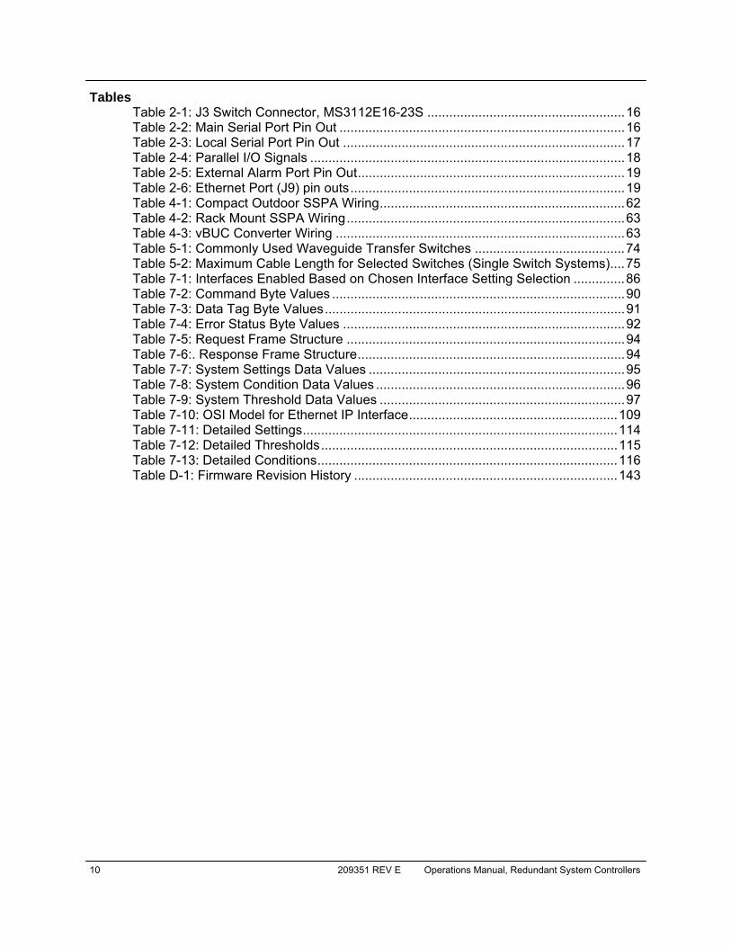
Tables Table 2-1: J3 Switch Connector, MS3112E16-23S ...................................................... 16 Table 2-2: Main Serial Port Pin Out .............................................................................. 16 Table 2-3: Local Serial Port Pin Out ............................................................................. 17 Table 2-4: Parallel I/O Signals ...................................................................................... 18 Table 2-5: External Alarm Port Pin Out ......................................................................... 19 Table 2-6: Ethernet Port (J9) pin outs ........................................................................... 19 Table 4-1: Compact Outdoor SSPA Wiring ................................................................... 62 Table 4-2: Rack Mount SSPA Wiring ............................................................................ 63 Table 4-3: vBUC Converter Wiring ............................................................................... 63 Table 5-1: Commonly Used Waveguide Transfer Switches ......................................... 74 Table 5-2: Maximum Cable Length for Selected Switches (Single Switch Systems) .... 75 Table 7-1: Interfaces Enabled Based on Chosen Interface Setting Selection .............. 86 Table 7-2: Command Byte Values ................................................................................ 90 Table 7-3: Data Tag Byte Values .................................................................................. 91 Table 7-4: Error Status Byte Values ............................................................................. 92 Table 7-5: Request Frame Structure ............................................................................ 94 Table 7-6:. Response Frame Structure ......................................................................... 94 Table 7-7: System Settings Data Values ...................................................................... 95 Table 7-8: System Condition Data Values .................................................................... 96 Table 7-9: System Threshold Data Values ................................................................... 97 Table 7-10: OSI Model for Ethernet IP Interface ......................................................... 109 Table 7-11: Detailed Settings ...................................................................................... 114 Table 7-12: Detailed Thresholds ................................................................................. 115 Table 7-13: Detailed Conditions .................................................................................. 116 Table D-1: Firmware Revision History ........................................................................ 143

Operations Manual, Redundant System Controllers 209351 REV E 11
Section 1: General Information
1.0 Introduction This section provides the general information for the Teledyne Paradise Datacom LLC line of Redundant Control Panels. The RCP2-1100 and RCP2-1200 are used for 1:1 and 1:2 redundant systems, respectively. The FPRC-1100 and FPRC-1200 are used for Phase Combined Solid State Power Amplifier (SSPA) systems. This section describes the supplied equipment and safety precautions. 1.1 Description The RCP2/FPRC controller is used to monitor and control amplifiers configured in 1:1 and 1:2 redundant systems. The RCP2-1100 and FPRC-1100 controllers provide control of two amplifiers and their corresponding transfer switch. The RCP2-1200 and FPRC-1200 controllers monitor and control three amplifiers and two switches. The RCP/FPRC Series of redundant controller can be used in LNA, LNB, and SSPA systems as well as frequency converter systems. A mimic display on the front panel indicates the RF path and the fault status of the equipment. User interface and control is provided in several forms:
• Front Panel, Local Control • 37-pin Parallel Control Port with Contact Closures and Opto-Isolated In-
puts • Serial Data Control via RS232 or RS485 (2 or 4-wire) • 10/100 Base-T Ethernet interface. Ethernet control options include em-
bedded web page, SNMP interface and propriety IP interface to connect over Teledyne Paradise Universal M&C software
Additional features include:
• Universal Input, Power Factor Corrected Power Supply • User Friendly Front Panel LCD Display for Local Monitor & Control • Dual AC Mains Entries with removable power supplies.
1.2 Equipment Supplied The following equipment is supplied with each unit:
• The RCP2/FPRC Redundant Controller • (2) IEC Line Cord Sets • Redundant Controller Operations Manual
12 209351 REV E Operations Manual, Redundant System Controllers
Optional Equipment includes: • Rack Slides • 100 ft. (30 m ) Control Cable • Switch Plate Mating Connector • DC Operation
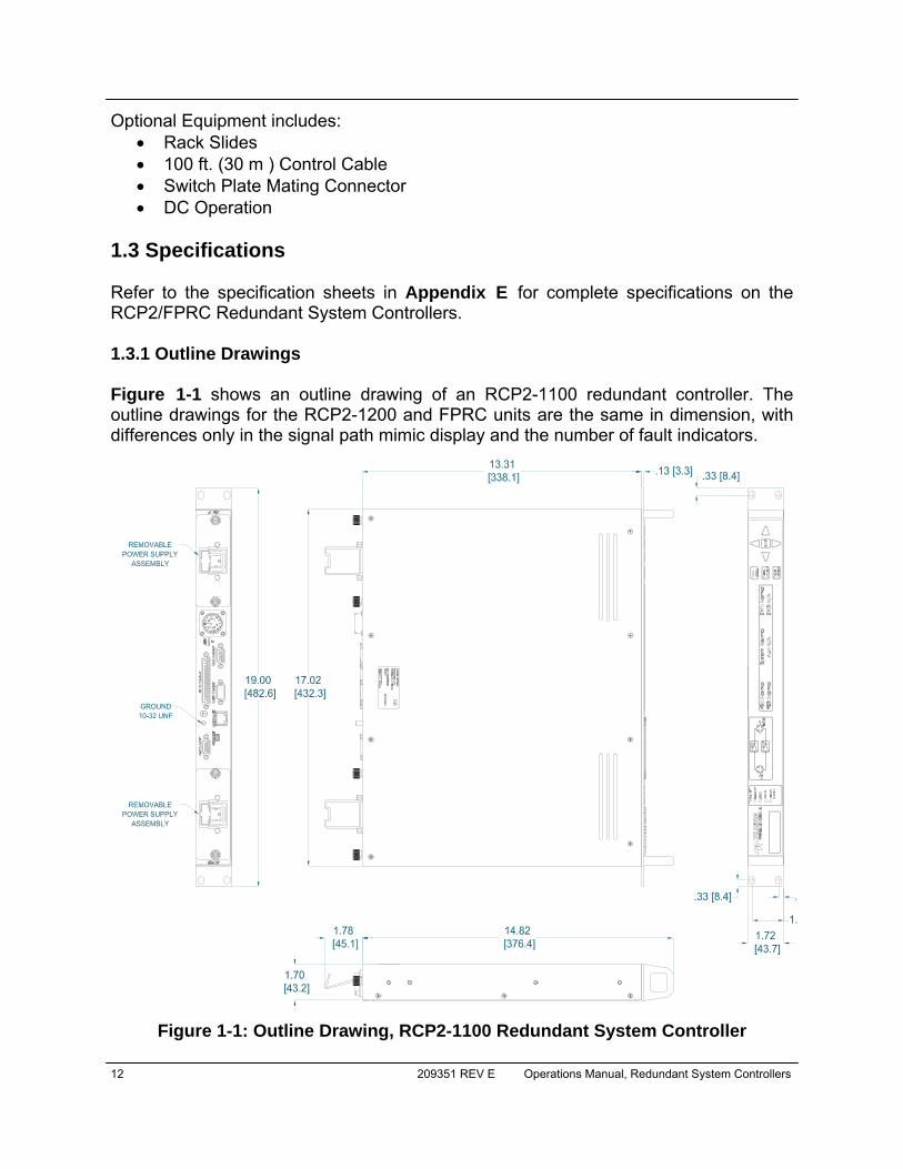
1.3 Specifications Refer to the specification sheets in Appendix E for complete specifications on the RCP2/FPRC Redundant System Controllers. 1.3.1 Outline Drawings Figure 1-1 shows an outline drawing of an RCP2-1100 redundant controller. The outline drawings for the RCP2-1200 and FPRC units are the same in dimension, with differences only in the signal path mimic display and the number of fault indicators.
Figure 1-1: Outline Drawing, RCP2-1100 Redundant System Controller
Operations Manual, Redundant System Controllers 209351 REV E 13
1.4 Safety Considerations Potential safety hazards exist unless proper precautions are observed when working with this unit. To ensure safe operation, the user must follow the information, cautions and warnings provided in this manual as well as the warning labels placed on the unit. 1.4.1 High Voltage Hazards
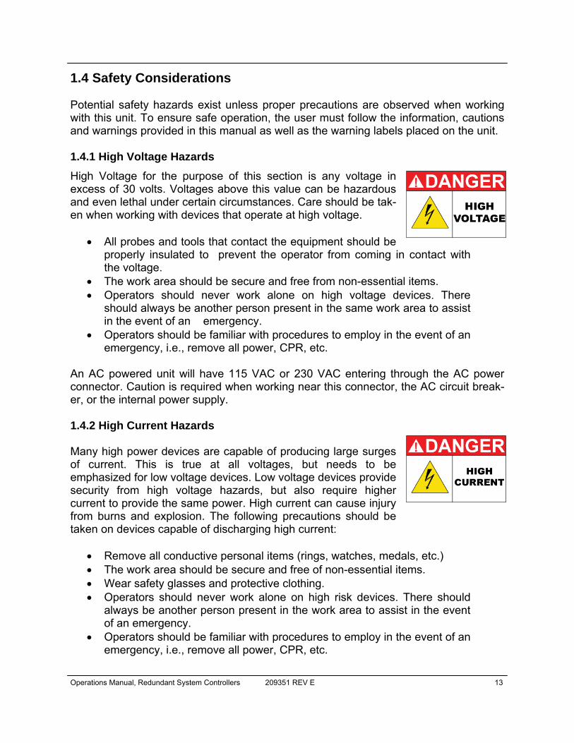
High Voltage for the purpose of this section is any voltage in excess of 30 volts. Voltages above this value can be hazardous and even lethal under certain circumstances. Care should be tak-en when working with devices that operate at high voltage.
• All probes and tools that contact the equipment should be properly insulated to prevent the operator from coming in contact with the voltage.
• The work area should be secure and free from non-essential items. • Operators should never work alone on high voltage devices. There
should always be another person present in the same work area to assist in the event of an emergency.
• Operators should be familiar with procedures to employ in the event of an emergency, i.e., remove all power, CPR, etc.
An AC powered unit will have 115 VAC or 230 VAC entering through the AC power connector. Caution is required when working near this connector, the AC circuit break-er, or the internal power supply. 1.4.2 High Current Hazards Many high power devices are capable of producing large surges of current. This is true at all voltages, but needs to be emphasized for low voltage devices. Low voltage devices provide security from high voltage hazards, but also require higher current to provide the same power. High current can cause injury from burns and explosion. The following precautions should be taken on devices capable of discharging high current:
• Remove all conductive personal items (rings, watches, medals, etc.) • The work area should be secure and free of non-essential items. • Wear safety glasses and protective clothing. • Operators should never work alone on high risk devices. There should
always be another person present in the work area to assist in the event of an emergency.
• Operators should be familiar with procedures to employ in the event of an emergency, i.e., remove all power, CPR, etc.

14 209351 REV E Operations Manual, Redundant System Controllers
1.4.3 Electrical Discharge Hazards A spark can not only create ESD reliability problems, it can also cause serious safety hazards. The following precautions should be taken when there is risk of electrical discharge:
• Follow all ESD guidelines • Remove all flammable material and solvents from the area. • All probes and tools that contact the equipment should be properly insu-
lated to prevent electrical discharge. • The work area should be secure and free from non-essential items. • Operators should never work alone on hazardous equipment. There
should always be another person present in the same work area to assist in the event of an emergency.
• Operators should be familiar with procedures to employ in the event of an emergency, i.e., remove all power, CPR, etc.
• Keep in mind that ground potential on both ends of long cable runs may be significantly different due to various factors. These ground potentials equalized by a cable ground signal line. Hence, it always a good practice to make connect/disconnect interface connectors when the equipment on both ends of a long cable run is powered down. This practice will mini-mize risk of damage of electrical interfaces due to unbalanced ground potentials.

Operations Manual, Redundant System Controllers 209351 REV E 15
2.0 Introduction This section provides information for the initial inspection, installation, and external connections for the RCP2/FPRC series redundant system controllers. 2.1 Inspection When the unit is received, an initial inspection should be completed. First ensure that the shipping container is not damaged. If it is, have a representative from the shipping company present when the container is opened. Perform a visual inspection of the equipment to make sure that all items on the packing list are enclosed. If any damage has occurred or if items are missing, contact: Teledyne Paradise Datacom LLC 328 Innovation Blvd., Suite 100 State College, PA 16803 USA Phone: +1 (814) 238-3450 Fax: +1 (814) 238-3829 2.2 Mounting The Teledyne Paradise Datacom Redundant System Controller is designed to be mounted in a standard EIA 19 inch equipment rack. The depth of the chassis, exclud-ing rear panel connectors, is 13.19 inches (335 mm). The height of the chassis is 1.7 inches (44 mm) or 1 rack unit. Optional 22 inch (559 mm) rack slides with extensions are available. 2.3 Storage and Shipment To protect the RCP2/FPRC during storage or shipping, use high quality commercial packing methods. Reliable commercial packing and shipping companies have the facilities and materials to adequately repack the equipment. 2.4 Cable Connections The RCP2/FPRC controller has a wide range of I/O interconnections available at the rear panel. The controller rear panel is shown in Figure 2-1.
Section 2: Description
Figure 2-1: RCP2/FPRC-1100/1200 Rear Panel (Standard AC Input)
16 209351 REV E Operations Manual, Redundant System Controllers
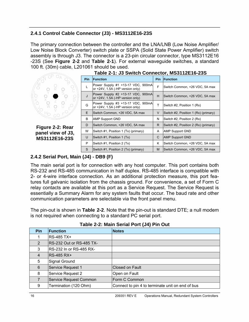
2.4.1 Control Cable Connector (J3) - MS3112E16-23S The primary connection between the controller and the LNA/LNB (Low Noise Amplifier/Low Noise Block Converter) switch plate or SSPA (Solid State Power Amplifier) switch assembly is through J3. The connector is a 23-pin circular connector, type MS3112E16-23S (See Figure 2-2 and Table 2-1). For external waveguide switches, a standard 100 ft. (30m) cable, L201061 should be used.
2.4.2 Serial Port, Main (J4) - DB9 (F)
The main serial port is for connection with any host computer. This port contains both RS-232 and RS-485 communication in half duplex. RS-485 interface is compatible with 2- or 4-wire interface connection. As an additional protection measure, this port fea-tures full galvanic isolation from the chassis ground. For convenience, a set of Form C relay contacts are available at this port as a Service Request. The Service Request is essentially a Summary Alarm for any system faults that occur. The baud rate and other communication parameters are selectable via the front panel menu. The pin-out is shown in Table 2-2. Note that the pin-out is standard DTE; a null modem is not required when connecting to a standard PC serial port.
Figure 2-2: Rear panel view of J3, MS3112E16-23S
Pin Function Pin Function
L Power Supply #1 +13-17 VDC, 900mA or +24V, 1.5A (-HP version only) F Switch Common, +26 VDC, 5A max
J Power Supply #2 +13-17 VDC, 900mA or +24V, 1.5A (-HP version only) H Switch Common, +26 VDC, 5A max
G Power Supply #3 +13-17 VDC, 900mA or +24V, 1.5A (-HP version only) T Switch #2, Position 1 (Rx)
E Switch Common, +26 VDC, 5A max V Switch #2, Position 1 (Rx) (primary)
B AMP Support GND N Switch #2, Position 2 (Rx)
D Switch Common, +26 VDC, 5A max R Switch #2, Position 2 (Rx) (primary)
W Switch #1, Position 1 (Tx) (primary) A AMP Support GND
U Switch #1, Position 1 (Tx) C AMP Support GND
P Switch #1, Position 2 (Tx) K Switch Common, +26 VDC, 5A max
S Switch #1, Position 2 (Tx) (primary) M Switch Common, +26 VDC, 5A max
Table 2-1: J3 Switch Connector, MS3112E16-23S
Table 2-2: Main Serial Port (J4) Pin Out Pin Function Notes 1 RS-485 TX+ 2 RS-232 Out or RS-485 TX- 3 RS-232 In or RS-485 RX- 4 RS-485 RX+ 5 Signal Ground 6 Service Request 1 Closed on Fault 8 Service Request 2 Open on Fault 7 Service Request Common Form C Common 9 Termination (120 Ohm) Connect to pin 4 to terminate unit on end of bus

Operations Manual, Redundant System Controllers 209351 REV E 17
If required, a 120 ohm RS-485 termination resistor is provided at pin 9. It should be connected to pin 4 to provide a 120 ohm termination on the RS-485 bus. 2.4.3 Serial Port, Local (J5) - DB9 (M)
The local serial port is used to support special transceiver systems and remote control panels. The baud rate of this port is fixed at 9600 Baud and cannot be changed. J5 is permanently configured for RS-485 half duplex communication. Table 2-3 details the local serial port pin-out. Port features full galvanic isolation from chassis ground.
2.4.4 Service Port (J6) - Mini USB A 5-contact Mini USB connector is used to provide flash re-programmability for the RCP controller card. In order to reload controller board firmware, connect this port to a standard PC USB port. See Section 6 for a description of the firmware upgrade proce-dure. 2.4.5 Parallel I/O Connector (J7) - DB37 (F)
The RCP controller has a full compliment of parallel monitor and control lines. A 37-pin D sub-style connector is used for the parallel I/O signals, which are detailed in Table 2-4. Ten Form-C relays are used for converter, switch position, and mode control. Each Form-C contact has a rating of 30 VDC @ 0.5 A, 110 VDC @ 0.3 A, and 125 VAC @ 0.5 A. The inputs and ground pins are isolated from the rest of the unit’s cir-cuitry. Inputs are activated by pulling it down to the isolated ground pin. In order to fully utilize the built-in inputs protection, it is recommended to keep the input’s ground iso-lated from the chassis ground.
Table 2-3: Local Serial Port (J5) Pin Out Function Pin Notes RS-485 RX+ 1 RS-485 RX- 2 RS-485 TX- 3 RS-485 TX+ 4 Signal Ground 5 Termination (120 Ohm) 9 Connect to pin 1 to terminate unit on end of bus

18 209351 REV E Operations Manual, Redundant System Controllers
Table 2-4: Parallel I/O Signals Identification Signal Pin Function Notes
Amp 1 Alarm Output
1 Closed on Fault Relay Contacts: 30VDC @ 0.5A
20 Common
2 Open on Fault
Amp 2 Alarm Output
21 Closed on Fault Relay Contacts: 30VDC @ 0.5A
3 Common
22 Open on Fault
Amp 3 Alarm Output
4 Closed on Fault
23 Common
5 Open on Fault
Auto / Manual Mode Output
24 Closed on Manual
6 Common
25 Closed on Auto
Local / Remote Mode Output
7 Closed on Local
26 Common
8 Closed on Remote
Switch #1 Position Output
27 Switch #1, Position 1
9 Common
28 Switch #1, Position 2
Switch #2 Position Output
10 Switch #2, Position 1
29 Common
11 Switch #2, Position 2
Power Supply #1 Alarm Output
30 Closed on Fault
12 Common
31 Open on Fault
Output
13 Closed on Fault
32 Common
14 Open on Fault
Priority Setting Output
33 Closed on Priority 2 15 Common
34 Closed on Priority 1
Fault Clear Input 37 Ground to Activate 5mA max current on all inputs
Priority Select Input 17 Ground to Activate Toggle Function
Auto / Manual Input 16 Ground to Activate Toggle Function; Alt Funct.: Ext. Mute Input
Amp 3 Standby Input 36 Ground to Activate
Amp 2 Standby Input 35 Ground to Activate
Amp 1 Standby Input 18 Ground to Activate
Inputs Ground (isolated) Common 19
Power Supply #2 Alarm
Operations Manual, Redundant System Controllers 209351 REV E 19
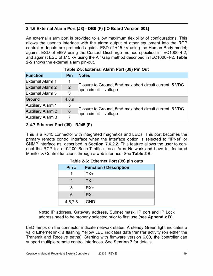
2.4.6 External Alarm Port (J8) - DB9 (F) [IO Board Version 001] An external alarm port is provided to allow maximum flexibility of configurations. This allows the user to interface with the alarm output of other equipment into the RCP controller. Inputs are protected against ESD of ±15 kV using the Human Body model; against ESD of ±8kV using the Contact Discharge method specified in IEC1000-4-2; and against ESD of ±15 kV using the Air Gap method described in IEC1000-4-2. Table 2-5 shows the external alarm pin-out.
2.4.7 Ethernet Port (J9) - RJ45 (F) This is a RJ45 connector with integrated magnetics and LEDs. This port becomes the primary remote control interface when the Interface option is selected to “IPNet” or SNMP interface as described in Section 7.6.2.2. This feature allows the user to con-nect the RCP to a 10/100 Base-T office Local Area Network and have full-featured Monitor & Control functions through a web interface. See Table 2-6.
Note: IP address, Gateway address, Subnet mask, IP port and IP Lock address need to be properly selected prior to first use (see Appendix B).
LED lamps on the connector indicate network status. A steady Green light indicates a valid Ethernet link; a flashing Yellow LED indicates data transfer activity (on either the Transmit and Receive paths). Starting with firmware version 6.00, the controller can support multiple remote control interfaces. See Section 7 for details.
Pin # Function / Description 1 TX+
2 TX-
3 RX+
6 RX-
4,5,7,8 GND
Table 2-6: Ethernet Port (J9) pin outs
Table 2-5: External Alarm Port (J8) Pin Out Function Pin Notes External Alarm 1 1
Closure to Ground, 5mA max short circuit current, 5 VDC open circuit voltage External Alarm 2 2
External Alarm 3 3 Ground 4,8,9 Auxiliary Alarm 1 5
Closure to Ground, 5mA max short circuit current, 5 VDC open circuit voltage Auxiliary Alarm 2 6
Auxiliary Alarm 3 7

20 209351 REV E Operations Manual, Redundant System Controllers
2.5 Prime Power Connection (J1, J2) Two separate removable power supplies are provided for fully redundant operation. Either of the two supplies is capable of operating the system and its associated switch-es. Two AC power connectors are provided on the rear panel (J1,J2). 2.6 Removable Power Supply Modules The RCP unit has a redundant power supply array consisting of two modules. A failed power supply module may be removed from the RCP chassis by loosening the two captured thumbscrews and sliding the module out of the chassis, then unplugging the quick-disconnect power pole connectors. 2.6.1 24V Power Supply Module Figure 2-3 shows an outline drawing of a power supply module.
The following list comprises the specifications for the standard power supply module: Plug: IEC, 250V, 10A, Male plug with wire-form AC Cable Clamp Fuse: 2 Amp 5x20mm Power Supply: 85-264 V input, 28V output, 175W Connector to RCP chassis: Quick-connect Power pole
See Section 6.4 for directions on identifying and replacing a failed power supply module.
Figure 2-3: Removable Power Supply Module

Operations Manual, Redundant System Controllers 209351 REV E 21
2.6.2 24V Power Supply Module, High Power option Figure 2-4 shows an outline drawing of a power supply module for units utilizing the High Power (-HP) option.
The following list comprises the specifications for the standard power supply module: Plug: IEC, 250V, 10A, Male plug Fuse: 2 Amp 5x20mm Power Supply: 85-264 V input, 28V output, 175W Fan: 40mm, 24V, 4.9 CFM Connector to RCP chassis: Quick-connect Power pole
See Section 6.4 for directions on identifying and replacing a failed power supply module.
Figure 2-4: Removable Power Supply Module, High Power option
22 209351 REV E Operations Manual, Redundant System Controllers
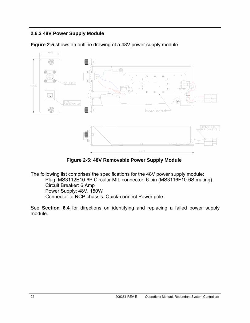
2.6.3 48V Power Supply Module Figure 2-5 shows an outline drawing of a 48V power supply module.
The following list comprises the specifications for the 48V power supply module:
Plug: MS3112E10-6P Circular MIL connector, 6-pin (MS3116F10-6S mating) Circuit Breaker: 6 Amp Power Supply: 48V, 150W Connector to RCP chassis: Quick-connect Power pole
See Section 6.4 for directions on identifying and replacing a failed power supply module.
Figure 2-5: 48V Removable Power Supply Module

Operations Manual, Redundant System Controllers 209351 REV E 23
Section 3: Front Panel Overview & Operation
3.0 Introduction The front panel is used to locally control the system. Figure 3-1 shows the front panel of a 1 RU RCP2/FPRC controller.
3.0.1 System Identification A label on the lower left hand corner of the controller front panel displays the model number and a brief description of the unit. The serial number is located on the rear panel of the controller. 3.0.2 Fault Indicators The fault indicator LEDs illuminate RED when the corresponding fault condition occurs. There are fault lights for Summary, Unit 1, Unit 2, and Power Supply faults. The RCP2-1200 and FPRC-1200 also includes a fault light for Unit 3. See Figure 3-2.
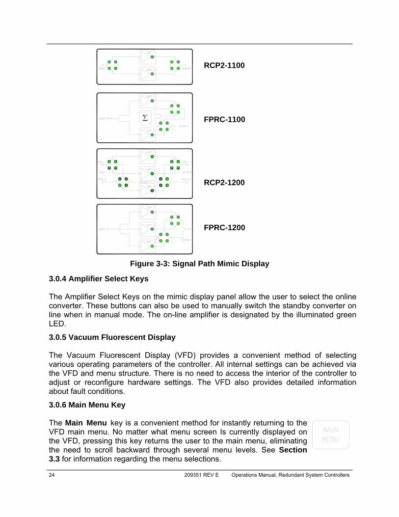
3.0.3 Signal Path Mimic Display The front panel mimic display provides a visual representation of the redundant system block diagram. Green LEDs indicate the position of the transfer switches showing the RF signal path from the RF input to the RF output. Figure 3-3 shows the various signal path mimic displays based on the controller model.
Figure 3-1: RCP2/FPRC Front Panel, showing RCP2-1200 Mimic Display
Figure 3-2: Fault Indicators The image at left shows the fault indicators for models RCP2-1100 and FPRC-1100; the figure at right shows the fault indicators for models RCP2-1200 and FPRC-1200.
SYSTEM IDENTIFICATION LABEL AMPLIFIER SELECT KEYS VACUUM FLOURESCENT DISPLAY AUTO/MANUAL TOGGLE LOCAL/REMOTE TOGGLE
FAULT INDICATOR PANEL SIGNAL PATH MIMIC DISPLAY MAIN MENU KEY NAVIGATION BUTTONS
24 209351 REV E Operations Manual, Redundant System Controllers
3.0.4 Amplifier Select Keys The Amplifier Select Keys on the mimic display panel allow the user to select the online converter. These buttons can also be used to manually switch the standby converter on line when in manual mode. The on-line amplifier is designated by the illuminated green LED.
3.0.5 Vacuum Fluorescent Display The Vacuum Fluorescent Display (VFD) provides a convenient method of selecting various operating parameters of the controller. All internal settings can be achieved via the VFD and menu structure. There is no need to access the interior of the controller to adjust or reconfigure hardware settings. The VFD also provides detailed information about fault conditions.
3.0.6 Main Menu Key The Main Menu key is a convenient method for instantly returning to the VFD main menu. No matter what menu screen Is currently displayed on the VFD, pressing this key returns the user to the main menu, eliminating the need to scroll backward through several menu levels. See Section 3.3 for information regarding the menu selections.
RCP2-1100 FPRC-1100 RCP2-1200 FPRC-1200
Figure 3-3: Signal Path Mimic Display
∑

Operations Manual, Redundant System Controllers 209351 REV E 25
3.0.7 Local / Remote Key The Local/Remote key selects whether the controller is operational by front panel (local) control or by remote control. Remote control includes both the rear panel parallel control signals as well as the serial communi-cation. 3.0.8 Auto / Manual Key This key selects between Auto and Manual Switching Mode. In Auto mode a converter failure will result in automatic switching of the system’s transfer switches. In manual mode a converter failure will result in fault alarms but no switchover will occur. 3.0.9 Display Navigation Keys The display navigation keys allow easy movement through the VFD menu structure. Both right and left as well as up and down movement is available using the triangular shaped keys. 3.0.10 Enter Key The enter key is used to select a given menu item. In conjunction with the navigation keys, it is easy to locate and select a desired function.
26 209351 REV E Operations Manual, Redundant System Controllers
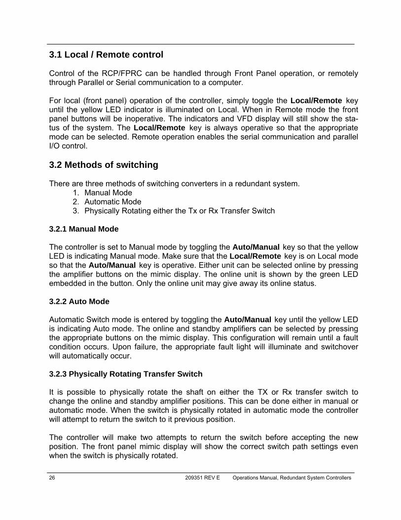
3.1 Local / Remote control Control of the RCP/FPRC can be handled through Front Panel operation, or remotely through Parallel or Serial communication to a computer. For local (front panel) operation of the controller, simply toggle the Local/Remote key until the yellow LED indicator is illuminated on Local. When in Remote mode the front panel buttons will be inoperative. The indicators and VFD display will still show the sta-tus of the system. The Local/Remote key is always operative so that the appropriate mode can be selected. Remote operation enables the serial communication and parallel I/O control. 3.2 Methods of switching There are three methods of switching converters in a redundant system.
1. Manual Mode 2. Automatic Mode 3. Physically Rotating either the Tx or Rx Transfer Switch
3.2.1 Manual Mode The controller is set to Manual mode by toggling the Auto/Manual key so that the yellow LED is indicating Manual mode. Make sure that the Local/Remote key is on Local mode so that the Auto/Manual key is operative. Either unit can be selected online by pressing the amplifier buttons on the mimic display. The online unit is shown by the green LED embedded in the button. Only the online unit may give away its online status. 3.2.2 Auto Mode Automatic Switch mode is entered by toggling the Auto/Manual key until the yellow LED is indicating Auto mode. The online and standby amplifiers can be selected by pressing the appropriate buttons on the mimic display. This configuration will remain until a fault condition occurs. Upon failure, the appropriate fault light will illuminate and switchover will automatically occur. 3.2.3 Physically Rotating Transfer Switch It is possible to physically rotate the shaft on either the TX or Rx transfer switch to change the online and standby amplifier positions. This can be done either in manual or automatic mode. When the switch is physically rotated in automatic mode the controller will attempt to return the switch to it previous position. The controller will make two attempts to return the switch before accepting the new position. The front panel mimic display will show the correct switch path settings even when the switch is physically rotated.
Operations Manual, Redundant System Controllers 209351 REV E 27
3.3 Local (Front Panel) Menu Structure
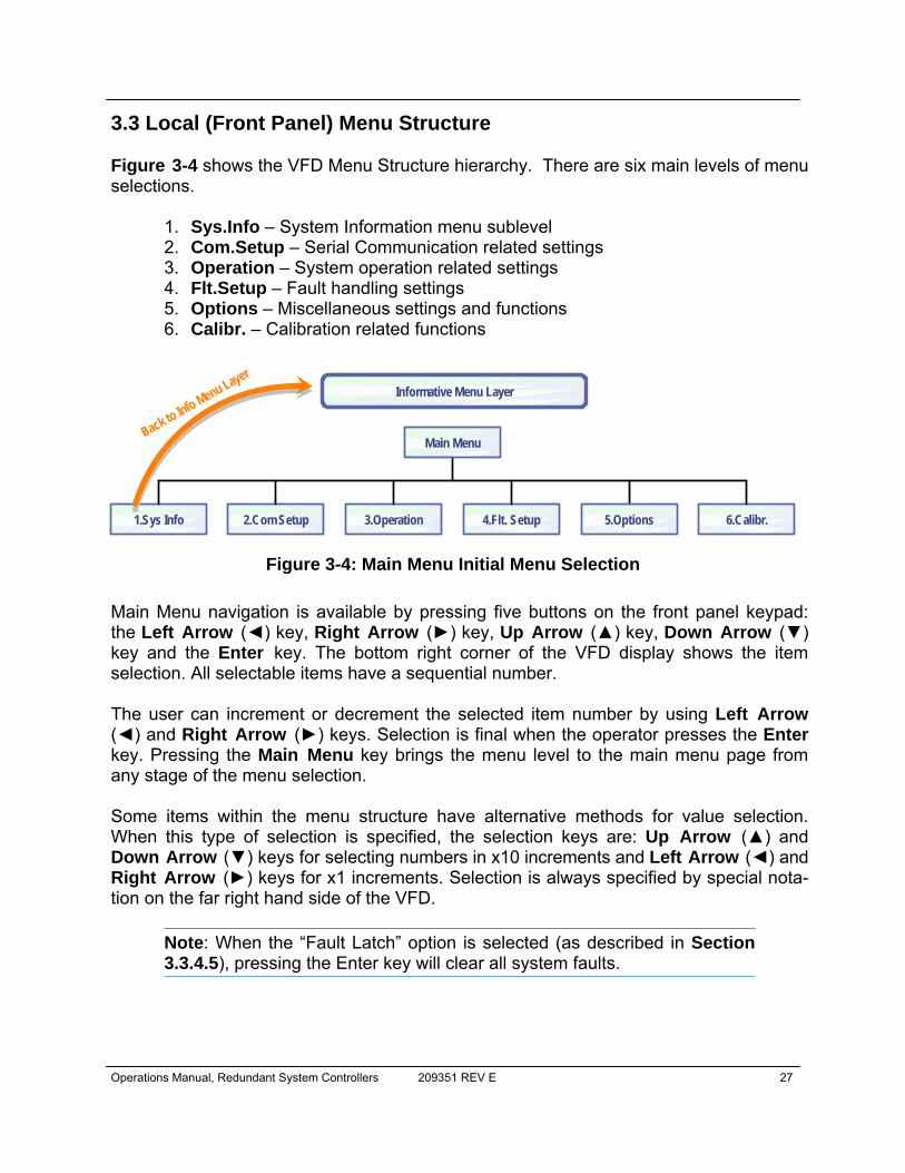
Figure 3-4 shows the VFD Menu Structure hierarchy. There are six main levels of menu selections.
1. Sys.Info – System Information menu sublevel 2. Com.Setup – Serial Communication related settings 3. Operation – System operation related settings 4. Flt.Setup – Fault handling settings 5. Options – Miscellaneous settings and functions 6. Calibr. – Calibration related functions
Main Menu navigation is available by pressing five buttons on the front panel keypad: the Left Arrow (◄) key, Right Arrow (►) key, Up Arrow (▲) key, Down Arrow (▼) key and the Enter key. The bottom right corner of the VFD display shows the item selection. All selectable items have a sequential number. The user can increment or decrement the selected item number by using Left Arrow (◄) and Right Arrow (►) keys. Selection is final when the operator presses the Enter key. Pressing the Main Menu key brings the menu level to the main menu page from any stage of the menu selection. Some items within the menu structure have alternative methods for value selection. When this type of selection is specified, the selection keys are: Up Arrow (▲) and Down Arrow (▼) keys for selecting numbers in x10 increments and Left Arrow (◄) and Right Arrow (►) keys for x1 increments. Selection is always specified by special nota-tion on the far right hand side of the VFD.
Note: When the “Fault Latch” option is selected (as described in Section 3.3.4.5), pressing the Enter key will clear all system faults.
Figure 3-4: Main Menu Initial Menu Selection
2.Com Setup1.Sys Info 3.Operation 4.Flt. Setup 6.Calibr.
Main Menu
Informative Menu Layer
Back to Info Menu Layer
5.Options
28 209351 REV E Operations Manual, Redundant System Controllers
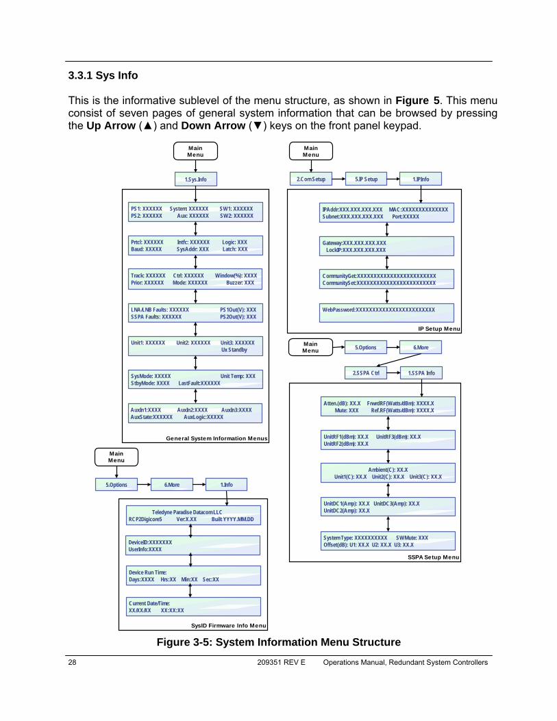
3.3.1 Sys Info This is the informative sublevel of the menu structure, as shown in Figure 5. This menu consist of seven pages of general system information that can be browsed by pressing the Up Arrow (▲) and Down Arrow (▼) keys on the front panel keypad.
Figure 3-5: System Information Menu Structure
1.Sys.Info
PS1: XXXXXX System: XXXXXX SW1: XXXXXXPS2: XXXXXX Aux: XXXXXX SW2: XXXXXX
Prtcl: XXXXXX Intfc: XXXXXX Logic: XXXBaud: XXXXX SysAddr: XXX Latch: XXX
Track: XXXXXX Ctrl: XXXXXX Window(%): XXXXPrior: XXXXXX Mode: XXXXXX Buzzer: XXX
LNA/LNB Faults: XXXXXX PS1Out(V): XXXSSPA Faults: XXXXXX PS2Out(V): XXX
Unit1: XXXXXX Unit2: XXXXXX Unit3: XXXXXX Ux Standby
SysMode: XXXXX Unit Temp: XXXStbyMode: XXXX LastFault:XXXXXX
IPAddr:XXX.XXX.XXX.XXX MAC:XXXXXXXXXXXXXXSubnet:XXX.XXX.XXX.XXX Port:XXXXX
Gateway:XXX.XXX.XXX.XXX LockIP:XXX.XXX.XXX.XXX
CommunityGet:XXXXXXXXXXXXXXXXXXXXXXXXCommunitySet:XXXXXXXXXXXXXXXXXXXXXXXX
WebPassword:XXXXXXXXXXXXXXXXXXXXXXXX
Teledyne Paradise Datacom LLCRCP2Digicore5 Ver:X.XX Built YYYY.MM.DD
General System Information Menus
SysID Firmware Info Menu
IP Setup Menu
1.IPInfo
1.Info5.Options 6.More
MainMenu
2.Com Setup 5.IP Setup
MainMenu
MainMenu
Atten.(dB): XX.X FrwrdRF(Watts/dBm): XXXX.X Mute: XXX Ref.RF(Watts/dBm): XXXX.X
UnitRF1(dBm): XX.X UnitRF3(dBm): XX.XUnitRF2(dBm): XX.X
Ambient(C): XX.XUnit1(C): XX.X Unit2(C): XX.X Unit3(C): XX.X
UnitDC1(Amp): XX.X UnitDC3(Amp): XX.XUnitDC2(Amp): XX.X
SSPA Setup Menu
2.SSPA Ctrl
5.Options 6.MoreMainMenu
1.SSPA Info
System Type: XXXXXXXXXX SWMute: XXXOffset(dB): U1: XX.X U2: XX.X U3: XX.X
AuxIn1:XXXX AuxIn2:XXXX AuxIn3:XXXXAuxState:XXXXXX AuxLogic:XXXXX
DeviceID:XXXXXXXUserInfo:XXXX
Device Run Time:Days:XXXX Hrs:XX Min:XX Sec:XX
Current Date/Time:XX/XX/XX XX:XX:XX

Operations Manual, Redundant System Controllers 209351 REV E 29
RCP firmware version 3.40 introduced additional navigational features to the System In-formation Menu. These features allow the user to quickly switch between the general System Info menus and the SSPA System Info menus by pressing the Left Arrow (◄) and Right Arrow (►) keys on front panel keypad (See Figure 3-5). 3.3.1.1 Sys Info - Page 1 This page is the system information page of the Sys Info menu. This page shows the status of both power supplies PS1 and PS2. The controller monitors the output voltage of each internal power supply. The power supply voltage is considered “Normal” if its output voltage level is above 23V and “Fault” when output voltage drops below 22V. A power supply fault is always considered a major fault. Also included on page one of Sys Info is the System status. This is the status of the system summary alarm. The system status will be “Fault” or “Normal” according to the state of the various fault monitoring circuitry. Aux is the state of the auxiliary fault input. Auxiliary faults are user configurable. Depending on the system configuration they may be enabled or disabled and track opposite logic states. When auxiliary faults are enabled, they will always trigger a summary fault. Auxiliary faults can be paired with main system faults. When pairing mode is enabled, a detected fault will be treated as a fault in one of the units and could initiate switchover in redundant systems. SW1 and SW2 are the position and fault state indicators of the transfer switch(es) in the system. Possible states are: “POS1” (Switch position 1), “POS2” (Switch position 2), and “Fault”. In a system using only one switch, SW2 will display “N/A” (Not available).
Note on Switch Fault: If the controller cannot read the position indicator lines on the transfer switch, it will be considered to be in a fault condition. This can occur when a transfer switch becomes stuck between valid positions. The Summary fault state may or may not be triggered depending on the user settings. The default is to consider a switch fault as a minor fault and will not trigger a summary alarm.
3.3.1.2 Sys Info - Page 2 This page of the Sys Info menu pertains to the internal monitor and control settings of the RCP controller. Prtcl is the serial communication protocol settings. Possible settings are “Auto”, which automatically detects either Standard or Locus Communications protocol; or “Standard”, the Standard extended protocol.

30 209351 REV E Operations Manual, Redundant System Controllers
Baud is the serial communication Baud rate selection. The available Baud rates in-clude: “2400”, “4800”, “9600”, “19200”, and “38400”. Interfc is the physical interface used for serial communication. Available interfaces are: “RS-232”, “RS-485”, “IPNet” and “SNMP”. SysAddr sets the controller unique network address. The address range is 1 to 255. As with any RS-485 network, the address must be unique within the serial network. The controller will answer on serial commands only if its address matches the address sent in the serial packet. Logic refers to the fault state logic for the External Alarm Input port, J8. The factory default setting is a logic high state for external alarm fault status. This is consistent with (contact open = fault ) logic used in most systems. However, if used in a system that employ reverse logic, this setting can be used to adjust the RCP controller accordingly. Latch refers to the fault latching function. The possible states are “Enb” and “Dis” for fault latching enabled and fault latching disabled. The factory default state is for fault latching to be enabled. When fault latching is enabled, after a fault has been detected the controller will continue to indicate an alarm even after the external fault may have been removed. To clear a latched fault, press the Main Menu key, press the Enter key twice, select 1.Clear Faults and press the Enter key. 3.3.1.3 Sys Info - Page 3 This page pertains to the internal monitor and control settings of the RCP controller. Track refers to the method used to track major system faults. Valid states are “LNA”, “EXT” (External), “Both” and “SerialCom”. This option specifies which elements are to be included into the redundant system. The user can select fault tracking based on in-ternal current monitoring such as in LNA/LNB systems, by external inputs from the Ex-ternal Alarm port, J8, by both internal current monitoring and external input, or over se-rial communication. Prior displays the priority control of the system, and is only applicable to 1:2 redundant systems in which a priority must be assigned to the standby amplifier in the case that both online amplifiers exhibit failures. The priority setting determines the switch posi-tion (polarity) the system should assign to the standby amplifier, either “Pol1” or “Pol2”. Ctrl specifies “Local” or “Remote” mode of controller operation. When in Remote mode, all front panel keys are disabled with exception of the Local/Remote key. Mode indicates and selects the “Automatic” or “Manual” mode of the controller. This function can be accessed by the dedicated Auto/Manual key on the front panel.
Operations Manual, Redundant System Controllers 209351 REV E 31
Window allows the user to select the current window setting for fault detection in an LNA / LNB redundant system. The possible selections are: “8%”, “12%”, “15%”, and “20%” of the nominal operating DC bias current. The factory default setting is 12%. Buzzer allows the user to enable or disable the internal audible alarm. The factory default setting is enabled. 3.3.1.4 Sys Info - Page 4 This page pertains to the advanced system diagnostic features of the RCP controller. LNA/LNB Faults refers to the controlled state of the LNA/LNB system. This item shows the fault state of the individual LNAs/LNBs. If no faults are detected, the word “None” will be displayed. If fault tracking isn’t enabled (e.g., if the Track setting is set to Ext – External faults only), the state will be indicated as “N/A” – Not Available. If any LNA related faults are present in the system, this item will show them in format X-X-X, where X could be the number 1, 2 or 3. For example, if LNA1 is in a fault condition, the display will indicate “1----”; if all three LNAs are faulted, “1-2-3” will be displayed. SSPA Faults refers to the controlled state of the SSPA system. This item shows the fault state of each individual SSPA. If no faults are detected, the word “None” will be displayed. If fault tracking isn’t enabled (e.g., if the Track setting is set to LNA – LNA/LNB faults only), the state will be indicated as “N/A” – Not Available. If any SSPA faults are present in the system, this item will show them in format X-X-X, where X could be the number 1, 2 or 3. For example: if SSPA1 is in the fault condition, the display will indicate “1----”; if all three SSPAs are faulted, “1-2-3” will be displayed. PS1Out(V) indicates the output voltage of the controller’s internal power supply 1. The indicated value shows an instant reading of the power supply voltage with accuracy of 0.1V. Normally, this value should be in a range from 22V to 27V. PS2Out(V) indicates the output voltage of the controller’s internal power supply 2. The indicated value shows instant reading of the power supply voltage with accuracy of 0.1V. Normally, this value should be in range from 22V to 27V. 3.3.1.5 Sys Info - Page 5 This page pertains to the advanced system diagnostic features of the controller Unit1; Unit2; Unit3 – Items refer to the summary fault state of individual units attached to the RCP. The possible state is “Normal” for non-fault condition, “Fault” or “N/A” as not available.
32 209351 REV E Operations Manual, Redundant System Controllers
Ux Standby refers to the selected default standby unit. “x” can be a digit from 1 to 3 and indicates which unit was selected as the default standby unit. This unit is usually selected by the user in the initial RCP setup. The selected unit will remain on standby under RCP Manual mode, or when in Auto mode when all units are in “Normal” non-faulted condition). Under Auto mode, the default standby unit will be put online if re-quired. Under Auto mode, the RCP always keeps track of the unit’s reliability record and can reassign default standby state to the unit with the worst reliability record. The unit will be assigned automatically to the default standby state if its fault state was switched from “Normal” to “Fault” more then two times since the last user intervention. Any user intervention to the units standby setup will clear all reliability records. 3.3.1.6 Sys Info - Page 6 This page provides additional system information (firmware version 3.7.0 or better). System Mode (SysMode) provides information regarding the current controller opera-tion mode and switching logic. Indicated status: “1:1” for 1:1 Mode; “1:2” for 1:2 Mode; “1:1 Ph. Combine” for 1:1 Phase Combined Mode; “Dual 1:1” for Dual 1:1 Mode; “Single Sw” for Single Switch Mode; or “1:2 Ph. Combine” for 1:2 Phase Combined Mode. See Section 3.3.3.1. Unit Temp displays the controller card temperature in degrees Celsius. (Version 6.00). Standby Mode (StdbyMode) shows the operational mode of the standby amplifier. In “Hot” mode, when the amplifier is in standby mode, it is transmitting its signal to the dummy load. If the standby amplifier is switched to the online state, full output power is immediately available. In “Cold” mode, when the amplifier is in standby mode, it is mut-ed. If the standby amplifier is switched to the online state, it will unmute and will take several moments to achieve full output power. (Version 6.00). LastFault displays the cause of the last fault identified by the controller. Possible results include: AuxFlt (Auxiliary Fault); ColdSt (unit cold start power-up detected); HPAFlt (HPA Fault); LNAFlt (LNA/LNB fault); PSFlt (Power Supply fault); Other (unknown fault condi-tion); or None (no information about present/past fault conditions, such as after the Clear Faults function is implemented by the user). 3.3.1.7 Sys Info - Page 7 AuxIn# presents the detected logic state of the Auxiliary Input for each connected unit. Possible values include: “Hi” for logic high state; or “Lo” for logic low state. AuxState shows the state of the Auxiliary Fault based on the Auxiliary Fault Input and selected Auxiliary Fault Logic. The following statuses are valid: “Normal”, “Fault” or “N/A”.
Operations Manual, Redundant System Controllers 209351 REV E 33
AuxLogic shows the selected logic used to handle Auxiliary faults. Valid returns include: Enabled, Disabled, Invert, Switch, and Sw Invert. See Section 3.3.4.2. 3.3.1.8 SSPA Subsystem Information - Pages 1-5
Page 1: Lists conditions and settings common to all SSPAs in a subsystem. Page 2: Displays individual SSPA output power levels. Page 3: Shows individual SSPA core temperatures and ambient temperature. Page 4: Lists SSPA DC current consumption. Page 5: Presents additional subsystem settings, including system type, switch mute setting and individual unit attenuation offsets.
See Section 4.6 for a thorough description of this series of menus. 3.3.1.9 IP Info - Page 1 This page is available through the ComSetup menu, and shows settings related to the IP interface. See Figure 3-5.
IP Address: IP address of the RCP . Consult your network administrator to set this address according to your LAN configuration. MAC: Medium Access Control address of the RCP Ethernet controller. This address is factory preset. Subnet: IP subnet mask of the RCP. Consult your network administrator to set this address. IPPort: IP port value for the RCP. This address is valid only when IPNet protocol is selected. The port value should not be selected outside the existing services range to avoid access conflict on the M&C PC end.
3.3.1.10 IP Info - Page 2 This page shows RCP settings related to the IP interface.
Gateway: IP Gateway address. This address is used only if access to the RCP is provided from an outside LAN. If no such access is required, the address must be set to 0.0.0.0 LockIP: This address is used to increase the security measure for the IPNet pro-tocol. The RCP will answer a request which comes only from a specified IP ad-dress. To disable this feature, set this address value to 255.255.255.255. See Section 3.3.2.5 for details.
34 209351 REV E Operations Manual, Redundant System Controllers
3.3.1.11 IP Info - Page 3 This page shows RCP settings related to the IP interface.
• CommunityGet: Security string used in SNMP protocol for Get type requests. Set this value to match the value specified in the NMS or MIB browser. Maximum string length is 20 alpha-numeric characters. The string allows read operation for the RM SSPA SNMP agent.
• CommunitySet: Security string used in SNMP protocol for Set type requests. Set this value to match the value specified in the NMS or MIB browser. For security reasons this string must be different than the Community Get string. Maximum string length is 20 alpha-numeric charac-ters. The string allows write operation for the RM SSPA SNMP agent.
Community strings are essentially passwords. The user should use the same rules for selecting them as for any other passwords: no dictionary words, spouse names, etc. An alphanumeric string with mixed upper- and lower-case letters is generally a good idea. 3.3.1.12 IP Info - Page 4 This page contains information about the web password and Trap NMSIP.
• WebPassword — Displays the password for the web page interface. • TrapNMSIP — Shows the selected IP address for the SNMP trap recipient.
(Version 6.00). 3.3.1.13 Firmware Info - Page 1 (ver. 6.00) This page is available through the Operation Setup menu, and provides information about the SSPA micro-controller unit firmware revision level and build date. 3.3.1.14 Firmware Info - Page 2 (ver. 6.00) This page provides additional RCP2 information.
• DeviceID – RCP2 unique serial and model number. • UserInfo – User information string, which could be set over SNMP protocol
(see SNMP MIB info for details) 3.3.1.15 Device Run Time Page (ver. 6.00) This page displays how long the unit has been running, shown in the number of days, hours, minutes and seconds. A power cycle will reset this clock.

Operations Manual, Redundant System Controllers 209351 REV E 35
3.3.1.16 RCP2 Local Time Info Page (ver. 6.00) This page shows the optional device clock. The device clock is a user-selectable param-eter. User set time is power dependent; a backup capacitor is used to keep the clock running while the unit is powered down. The clock will needed to be set again if the unit remains without power for longer than 5 hours. The clock output format as follows: Year/Month/Day Hours:Minutes:Seconds. At this time, only the 24-hour clock format is supported.
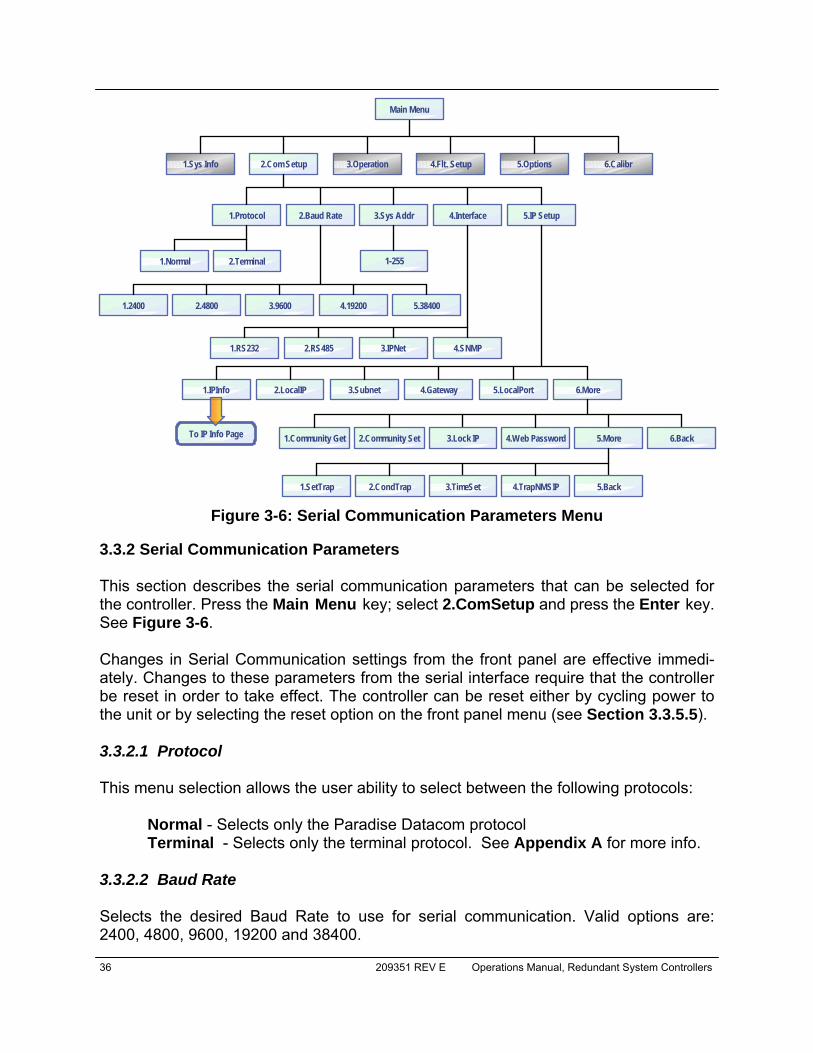
36 209351 REV E Operations Manual, Redundant System Controllers
3.3.2 Serial Communication Parameters This section describes the serial communication parameters that can be selected for the controller. Press the Main Menu key; select 2.ComSetup and press the Enter key. See Figure 3-6. Changes in Serial Communication settings from the front panel are effective immedi-ately. Changes to these parameters from the serial interface require that the controller be reset in order to take effect. The controller can be reset either by cycling power to the unit or by selecting the reset option on the front panel menu (see Section 3.3.5.5). 3.3.2.1 Protocol This menu selection allows the user ability to select between the following protocols:
Normal - Selects only the Paradise Datacom protocol Terminal - Selects only the terminal protocol. See Appendix A for more info.
3.3.2.2 Baud Rate Selects the desired Baud Rate to use for serial communication. Valid options are: 2400, 4800, 9600, 19200 and 38400.
Figure 3-6: Serial Communication Parameters Menu
2.Com Setup
3.Sys Addr
1.2400
1.RS232
3.Subnet
1.Community Get
1.Sys Info
2.Baud Rate
2.Terminal 1-255
2.LocalIP
3.Operation
4.Interface
2.4800
2.RS485
4.Gateway
2.Community Set
4.Flt. Setup
5.IP Setup
3.9600
3.IPNet
5.LocalPort
4.Web Password
5.Options
4.19200
4.SNMP
6.More
1.Protocol
1.Normal
5.38400
1.IPInfo
Main Menu
6.Calibr
To IP Info Page 3.Lock IP 5.More 6.Back
1.SetTrap 2.CondTrap 4.TrapNMSIP3.TimeSet 5.Back
Operations Manual, Redundant System Controllers 209351 REV E 37
3.3.2.3 Sys. Address Sets the network address of the controller if used in a RS485 network. Address is selectable from 1 to 255 3.3.2.4 Interface This menu choice provides the selection of the physical interface of the main serial port. Choose between RS-232, RS-485, IPNet (Ethernet) and SNMP interfaces. Starting with Firmware version 6.00, the RCP controller allow simultaneous support of multiple remote control interfaces. Refer to Section 7 for more details. 3.3.2.5 IP Setup This menu allows the user to select between the following menu items:
• 1.IPInfo - This selection allows the user to review all IPNet settings as described in Section 3.3.1.8 through Section 3.3.1.11.
• 2.Local IP - This selection allows the user to set the unit’s Local IP Ad-dress. Factory default for standalone units is 192.168.0.9.
• 3.Subnet Mask - This selection allows the user to set the unit’s Subnet Mask. Factory default is 255.255.255.0.
• 4.Default Gateway - This selection allows the user to set the unit’s De-fault Gateway. Factory default is 192.168.0.1.
• 5.Local Port - This selection allows the user to set the unit’s Local Port. The default Local Port address is 1007.
• 6.More - This selection opens the menu items listed in Section 3.3.2.5.1. 3.3.2.5.1 More (SNMP, IP and Web Settings) This menu allows the user to set the Community String Selection (Set/Get) and assign the Web Password. Use the Up Arrow [▲] and Down Arrow [▼] keys to browse through selected charac-ters. Press the Up Arrow [▲] and Down Arrow [▼] keys simultaneously to erase the selected character. Press the Left Arrow [◄] and Right Arrow [►] keys to navigate within the string. Maximum length is 20 characters.
• 1.Community Get — This selection allows user to set the SNMP Com-munity Get String. Default is “public”;
• 2.Community Set — This selection allows user to set the SNMP Com-munity Set String. Default is “private”;
• 3.LockIP — This selection allows user to set the IP address from which requests will be accepted by the amplifier. The LockIP selection gives the

38 209351 REV E Operations Manual, Redundant System Controllers
user the ability to increase the security measure for the IPNet protocol. The SSPA will answer a request which comes only from the assigned IP ad-dress. For firmware prior to version 6.00, set this address value to 0.0.0.0 or 255.255.255.255 to disable this feature. Starting with version 6.00, the Lock IP address function has been updated to allow “Binding” and “Masking” functions. Binding" means that the first datagram retrieved for this socket will bind to the source IP address and port number. Once binding has been completed, the SSPA will answer to the bound IP source until the unit is restarted or reset. Without binding, the socket accepts datagrams from all source IP addresses. Address 0.0.0.0 allows all peers, but provides binding to first detected IP source; Address 255.255.255.255 accepts all peers, without binding. If Lock IP is a mul-ticast address, then the amplifier will accept queries sent from any IP ad-dress of multicast group;
• 4.WebPassword — This selection allows the user to set the password for the web interface. Default is “paradise”. Erase all characters to disable password protection;
• 5.More — This selection opens the menu items listed in Section 3.3.2.5.2. • 6.Back — This selection opens the menu items listed in Section 3.3.2.5.
3.3.2.5.2 More (Traps and Time Settings) This menu allows the user to set SNMP Trap settings, and also set the time of the inter-nal clock.
• 1.SetTrap — This selection allows the user to set the Settings Trap; • 2.CondTrap — This selection allows the user to set the Conditions Trap; • 3.TimeSet — This selection allows the user to set the time. Clock output
format is YY/MM/DD HH:mm. Only 24-Hour format is supported at this time. Press the Up Arrow [▲] key to increment the value highlighted by the cursor. Press the Down Arrow [▼] key to decrease the value highlight-ed by the cursor. Press the Right Arrow [►] key to move the cursor to the right; Press the Left Arrow [◄] key to move the cursor to the left; Press the Enter key to save the current setting.
• 4.TrapNMSIP — This selection allows the user to set the Trap NMS IP Ad-dress;
• 5.Back — This selection opens the menu items listed in Section 3.3.2.5.1.
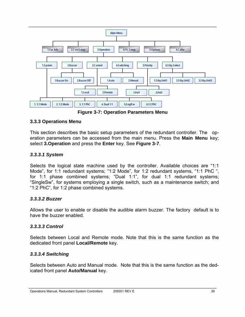
Operations Manual, Redundant System Controllers 209351 REV E 39
3.3.3 Operations Menu This section describes the basic setup parameters of the redundant controller. The op-eration parameters can be accessed from the main menu. Press the Main Menu key; select 3.Operation and press the Enter key. See Figure 3-7. 3.3.3.1 System Selects the logical state machine used by the controller. Available choices are “1:1 Mode”, for 1:1 redundant systems; “1:2 Mode”, for 1:2 redundant systems, “1:1 PhC “, for 1:1 phase combined systems; “Dual 1:1”, for dual 1:1 redundant systems; “SingleSw”, for systems employing a single switch, such as a maintenance switch; and “1:2 PhC”, for 1:2 phase combined systems. 3.3.3.2 Buzzer Allows the user to enable or disable the audible alarm buzzer. The factory default is to have the buzzer enabled. 3.3.3.3 Control Selects between Local and Remote mode. Note that this is the same function as the dedicated front panel Local/Remote key. 3.3.3.4 Switching Selects between Auto and Manual mode. Note that this is the same function as the ded-icated front panel Auto/Manual key.
Figure 3-7: Operation Parameters Menu
2.Com Setup1.Sys Info
2.Buzzer
3.Operation 4.Flt. Setup 5.Options
1.System
Main Menu
6.Calibr
3.Control 4.Switching 5.Priority 6.Stby Select
1. 1:1 Mode 2. 1:2 Mode 3. 1:1 PhC 4. Dual 1:1 5.SnglSw 6.1:2 PhC
2.Buzzer Off1.Buzzer On
2.Remote1.Local
2.Manual1.Auto
2.Pol21.Pol1
2.Stby.Unit21.Stby.Unit1 3.Stby.Unit3

40 209351 REV E Operations Manual, Redundant System Controllers
3.3.3.5 Priority Used in 1:2 redundant systems only. It is used to assign switching priority to either position 1 or position 3 in the event that both amplifiers fail. Priority has no effect in a FPRC-1200 system. 3.3.3.6 Stby. Select Selects which unit will be in default standby mode. Note that this is the same function as on the signal path mimic display on the front panel.

Operations Manual, Redundant System Controllers 209351 REV E 41
3.3.4 Fault Setup This section describes the fault tracking capability of the controller. The controller is extremely versatile in its ability to monitor alarms from a variety and quantity of equip-ment. The following alarm inputs are provided on the controller:
• LNA / LNB Current Monitoring - up to 600mA • (3) External Alarm Inputs • (5) Auxiliary Alarm Inputs
Any combination of the alarm inputs can be used individually or together. Press the Main Menu key; select 4.Flt.Setup and press the Enter key. See Figure 3-8. 3.3.4.1 Mjr.Faults Allows the operator to assign priority and select those inputs that constitute a major fault and cause switchover. Normally, only External fault tracking is enabled in a FPRC-1200 System.
• 1.LNA/LNB - Enables the current monitoring of LNA/LNB to create major fault alarm
• 2.External - Enables the (3) external alarm inputs of J8 • 3.Both - Allows both current monitoring and external alarms to create a
major fault. • 4.SerialCom - Allows tracking of a connected HPA fault state by reading
incoming data over the local control port. This option can be used in conjunction with the selected HPA subsystem in case the external alarm port is out of service.
Figure 3-8: Fault Setup Parameters Menu
2.Com Setup1.Sys Info 3.Operation 4.Flt. Setup 5.Options
1.Mjr. Faults
Main Menu
6.Calibr
2. Aux. Faults 3. Sw Faults 5.Flt.Latch
1.LNA/LNB 2.External 3.Both
1.Sys. Fault 2.Alert Only 3.Alternate
4.Flt. Logic
1.Fault on High 2.Fault on Low 1.Enable 2.Disable4.SerialCom
1.Enable 2.Disable 3.Invert 4.Switched 5.Sw Invert 6.Back 4.Back
42 209351 REV E Operations Manual, Redundant System Controllers
3.3.4.2 Aux.Faults Allows the operator to select fault handling of the (5) auxiliary fault inputs of J8 to create a major fault. Select one of the items listed below and press the Enter key to enable.
• 1.Disable – Auxiliary faults disabled; • 2.Enable – Enables independent auxiliary fault function. Fault inputs will
not be paired with main fault input channels and will not cause unit faults or switchover of the RCP2 unit. Fault logic follows major fault logic;
• 3.Invert – Enable independent auxiliary fault function. Fault inputs will not be paired with main fault input channels and will not cause unit faults or switchover of the RCP2 unit. Fault logic inverted from major fault logic;
• 4.Switched – Auxiliary fault enabled as chain redundancy indicator for HPA faults. Each Auxiliary channel will be paired up with the main fault channel. A detected auxiliary fault will be treated as a fault on the main fault channel and will lead to a relevant unit fault. Fault logic follows major fault logic;
• 5.Sw Invert – Auxiliary fault enabled as chain redundancy indicator for HPA faults. Each Auxiliary channel will be paired up with the main fault channel. A detected auxiliary fault will be treated as a fault on the main fault channel and will lead to a relevant unit fault. Fault logic is inverted from major fault logic.
• 6.Back — Select and press the Enter key to return to the Fault Setup menu of Section 3.3.4.
3.3.4.3 Sw.Faults Determines whether a switch fault should cause a major alarm and attempt to switch or simply alert to the problem on the front panel VFD (considered a minor alarm). Select one of the items listed below and press the Enter key to enable.
• 1.Sys.Fault - Major Alarm Mode, Summary alarm and switchover triggered.
• 2.Alert - Minor Alarm Mode, No summary alarm indicated; no switchover occurs.
• 3.Alternate – Same as Alert, but will alternate functions of the parallel I/O port output for the Switch position indicator form C-relays. Instead of indicating position (either Pos1 or Pos2), relays will indicate RF switch fault or normal status. This option was introduced in RCP firmware rev 3.30 for advanced system integration purposes. This option should not be selected by the customer unless advised by Teledyne Paradise Datacom LLC.
• 4.Back — Select and press the Enter key to return to the Fault Setup menu of Section 3.3.4.
Operations Manual, Redundant System Controllers 209351 REV E 43
3.3.4.4 Fault Logic Select between “Fault on High” and “Fault on Low”. 3.3.4.5 Fault Latch Determines the alarm reporting condition. A latched alarm will remain indicated on the front panel until the operator clears the alarm by pressing the “Enter” button. Unlatched alarms will allow the summary alarm indicator to stop displaying the alarm condition if the circumstance creating the alarm has be cleared or corrected.
• 1.Enable - Keeps alarm condition displayed until operator intervention. • 2.Disable - Unlatches the Alarm state
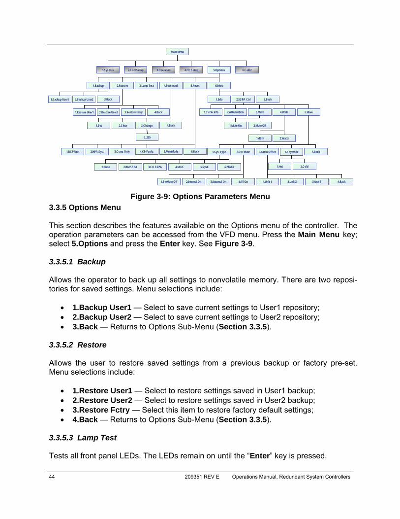
44 209351 REV E Operations Manual, Redundant System Controllers
3.3.5 Options Menu This section describes the features available on the Options menu of the controller. The operation parameters can be accessed from the VFD menu. Press the Main Menu key; select 5.Options and press the Enter key. See Figure 3-9. 3.3.5.1 Backup Allows the operator to back up all settings to nonvolatile memory. There are two reposi-tories for saved settings. Menu selections include:
• 1.Backup User1 — Select to save current settings to User1 repository; • 2.Backup User2 — Select to save current settings to User2 repository; • 3.Back — Returns to Options Sub-Menu (Section 3.3.5).
3.3.5.2 Restore Allows the user to restore saved settings from a previous backup or factory pre-set. Menu selections include:
• 1.Restore User1 — Select to restore settings saved in User1 backup; • 2.Restore User2 — Select to restore settings saved in User2 backup; • 3.Restore Fctry — Select this item to restore factory default settings; • 4.Back — Returns to Options Sub-Menu (Section 3.3.5).
3.3.5.3 Lamp Test Tests all front panel LEDs. The LEDs remain on until the “Enter” key is pressed.
Figure 3-9: Options Parameters Menu
2.Com Setup1.Sys Info 3.Operation 4.Flt. Setup 5.Options
Main Menu
6.Calibr
1.Backup 2.Restore 3.Lamp Test 4.Password 5.Reset 6.More
1.Restore User1 3.Restore Fctry
1.Set 2.Clear 3.Change
0..255
3.Back1.Info 2.SSPA Ctrl
4.Units3.Mute2.Attenuation
1.Sys. Type 2.Sw. Mute
1.SSPA Info
1.dBm 2.Watts
5.More
1.None 2.RM SSPA 3.CO SSPA 4.vBUC
3.Atten Offset
1.SwMute Off 2.Internal On 3.External On 4.All On 1.Unit 1 2.Unit 2 3.Unit 3
1.Backup User1 2.Backup User2 3.Back
2.Restore User2 4.Back
4.Back
1.RCP Unit 3.Coms Only2.HPA Sys. 4.Clr Faults 5.MemMode 6.Back 4.SbyMode 5.Back
1.Mute On 2.Mute Off
5.SysX 6.PMAX
4.Back
1.Hot 2.Cold
Operations Manual, Redundant System Controllers 209351 REV E 45
3.3.5.4 Password Allows the user to set, clear, or change a password that prohibits others from changing controller settings. Menu selections include:
• 1.Set — Enables password protection. Uses last saved number from 1-255;
• 2.Clear — Disables password protection; • 3.Change — Allows user to define the password. A number from 1-255
can be selected. Use the front panel navigation keys to set the number. The Up Arrow (▲) and Down Arrow (▼) keys change the number by fac-tors of 10. The Left Arrow (◄) and Right Arrow (►) keys change the number in increments of 1; Press the Enter key to accept the new pass-word.
• 4.Back — Returns to the Options Sub-Menu (Section 3.3.5). 3.3.5.5 Reset Allows the user to reset the controller hardware to activate certain settings. For example, when the IP Address is modified the unit must be reset for it to use the new IP Address. Firmware version 6.00 allows multiple reset levels for the unit:
• 1.RCP Unit — Resets all hardware on the removable M&C card of the unit. All communication links to remote M&C will be dropped until reset process is complete. The unit will start up using currently selected communication parameters (IP address, baud rate, etc). Command of a remote HPA sys-tem will not reset. However, power supplied by the unit to LNAs/LNBs will be turned off during reset and turned back on after reset is completed;
• 2.HPA Sys. — Sends full reset command to remote control HPA system • 3.Coms only — Resets only communication parameters. Remote COM
and IP links will be dropped and re-enabled with currently selected param-eters;
• 4.ClrFaults — Clears all latched faults and remaining fault history infor-mation. Unit remains fully operational during the process;
• 5.MemMode — Allows alternate settings retention function. Two choices are allowed: ○ FLASH — Default mode. Without user intervention, the unit will retain
this mode of operation. All changes to settings setup performed over local or remote interface will be backed up to EEPROM within 3 sec-onds. If the unit experiences a power cycle or reset, the last saved set of settings will be applied to the unit upon each power up or I/O card reset. Any EEPROM device has a limited ability to endure write cycles. Maximum write cycles for units with firmware version prior to 6.00 is 150,000 times. After exceeding this limit, the unit will operate in RAM

46 209351 REV E Operations Manual, Redundant System Controllers
mode, utilizing a default set of settings on each power up. Firmware version above 6.00 allows a minimum of 3,000,000 write cycles before opting out to RAM mode;
○ RAM — In this mode, the unit will not backup any settings changes to internal EEPROM. This mode is optional and needs to be set by the us-er every time when the unit endures a power cycle or I/O card reset. This mode is beneficial when frequent changes are necessary to the unit state (such as mute/unmute or attenuation changes). Since any EEPROM device has limited write cycles, RAM mode allows the user to execute unlimited settings changes. If the unit experiences a power or reset cycle in RAM mode, it will use the last saved settings setup before RAM was engaged;
3.3.5.6 More This allows access to the menus described in Sections 3.3.5.7, 3.3.5.8 and 3.3.5.9. 3.3.5.7 Info Provides access to the record of the firmware type, version and build date, as well as the device ID and run time. See Figure 3-5 (SysID Firmware Info Menu). 3.3.5.8 SSPA Ctrl This section deals with settings specific to SSPA systems.
• 1.SSPA Info – Provides access to the record of SSPA attenuation, mute status, forward and reflected power, individual SSPA output power, ambi-ent and SSPA core temperatures, SSPA current draw and other system information. See Figure 3-5 (System Setup Menu).
• 2.Attenuation – Allows the operator to vary the gain of the SSPA system from its maximum value to 20 dB below its maximum value. Use the Left Arrow (◄) and Right Arrow (►) keys to move the cursor; use the Up Ar-row (▲) key to increase the numerical value at the cursor; use the Down Arrow (▼) key to decrease the numerical value at the cursor. Press the Enter key to accept the entered value.
• 3.Mute – Select the SSPA mute function: 1.Mute On; 2.Mute Off. • 4.Units – Select either 1.dBm or 2.Watts as the display unit. • 5.More – This selection gives access to the following menu items:
○ 1.Sys.Type (System Type) – Select the controlled system type: 1.None, 2.RM (Rack Mount) SSPA, 3.CO (Compact Outdoor) SSPA, 4.vBUC, 5.SystemX (for custom systems), or 6.PMAX (PowerMAX).
○ 2.Sw.Mute (Switch Mute)– Select the switch mute option for the re-dundant system: 1.SWMute Off; 2.Internal On; 3.External On; 4.All On. See Section 4.5.2.3 for details.
Operations Manual, Redundant System Controllers 209351 REV E 47
○ 3.Atten.Offset (Attenuation Offsets) – Allows the operator to equal-ize the individual SSPA gain differential. The selected offset is added to the current level of system attenuation. The sum of the selected system attenuation and the offset setting is limited to 20 dB maxi-mum.
○ 4.SbyMode (Standby Mode) – (Version 6.00). Select either 1.Hot Standby or 2.Cold Standby. In Hot Standby mode, standby (offline) amplifier remains fully functional. It is transmitting output signal to the dummy load. Since the HPA is already fully operational there is no warm up period. In Hot Standby mode, full output power is immediate-ly available with highest possible gain stability. In Cold Standby mode, the offline unit is placed in a muted state. This mode of operation min-imizes power consumption and slightly improves overall unit MTBF. When the unit is placed online, it will be unmuted automatically. Once switched to the online state, the unit will be subject to warm up and temperature equalization transition its gain may fluctuate slightly (within specified range). Cold standby typically is not used in systems where maximum gain/output power stability is required.
○ 5.Back — Returns to the SSPA Ctrl Sub-Menu (Section 3.3.5.8). 3.3.5.9 Back Returns to the Options Sub-Menu (Section 3.3.5).
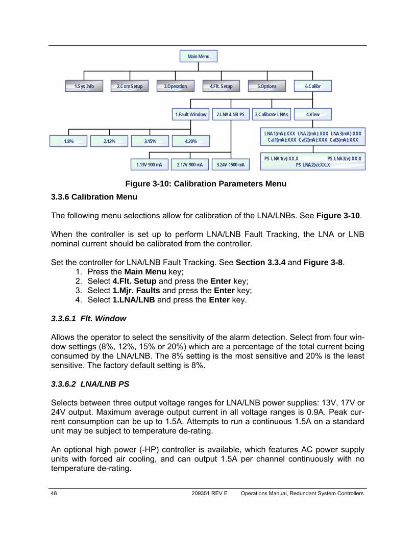
48 209351 REV E Operations Manual, Redundant System Controllers
3.3.6 Calibration Menu The following menu selections allow for calibration of the LNA/LNBs. See Figure 3-10. When the controller is set up to perform LNA/LNB Fault Tracking, the LNA or LNB nominal current should be calibrated from the controller. Set the controller for LNA/LNB Fault Tracking. See Section 3.3.4 and Figure 3-8.
1. Press the Main Menu key; 2. Select 4.Flt. Setup and press the Enter key; 3. Select 1.Mjr. Faults and press the Enter key; 4. Select 1.LNA/LNB and press the Enter key.
3.3.6.1 Flt. Window Allows the operator to select the sensitivity of the alarm detection. Select from four win-dow settings (8%, 12%, 15% or 20%) which are a percentage of the total current being consumed by the LNA/LNB. The 8% setting is the most sensitive and 20% is the least sensitive. The factory default setting is 8%. 3.3.6.2 LNA/LNB PS Selects between three output voltage ranges for LNA/LNB power supplies: 13V, 17V or 24V output. Maximum average output current in all voltage ranges is 0.9A. Peak cur-rent consumption can be up to 1.5A. Attempts to run a continuous 1.5A on a standard unit may be subject to temperature de-rating. An optional high power (-HP) controller is available, which features AC power supply units with forced air cooling, and can output 1.5A per channel continuously with no temperature de-rating.
Figure 3-10: Calibration Parameters Menu
2.Com Setup1.Sys Info 3.Operation 4.Flt. Setup 5.Options
1.Fault Window
Main Menu
6.Calibr
2.LNA/LNB PS 3.Calibrate LNAs 4.View
1.8% 2.12% 3.15% 4.20%
1.13V 900 mA 2.17V 900 mA
LNA1(mA):XXX LNA2(mA):XXX LNA3(mA):XXXCal1(mA):XXX Cal2(mA):XXX Cal3(mA):XXX
PS LNA1(v):XX.X PS LNA3(v):XX.XPS LNA2(v):XX.X3.24V 1500 mA
Operations Manual, Redundant System Controllers 209351 REV E 49
Warning! Some LNB models may not be compatible with 24V PS op-tion. To avoid potential equipment damage, refer to LNB technical data before enabling this voltage range!
Multiple voltage option can be used to switch between bands of dual or triple band LNB units or to connect higher power converters. All three channels will switch output voltage simultaneously. For a detailed description of LNB/LNA power supplies, refer to Section 5.0.1. 3.3.6.3 Calibrate Select and press the Enter key to calibrate the system LNAs at the current level. 3.3.6.4 View LNA Allows the user to view information about the system LNAs. The resulting window shows current draw values (in milliamps) and the calibration val-ues for each LNA in the system. The display will show “N/A” for LNA3 if the system is configured as a 1:1 redundant system. A secondary window, available by pressing the Down Arrow (▼) key, displays the Power Supply voltages for each LNA.

50 209351 REV E Operations Manual, Redundant System Controllers
THIS PAGE LEFT INTENTIONALLY BLANK
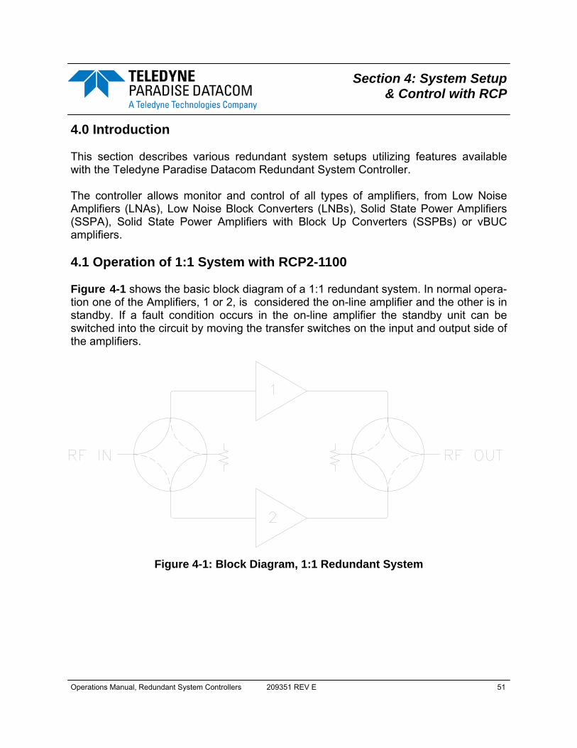
Operations Manual, Redundant System Controllers 209351 REV E 51
Section 4: System Setup & Control with RCP
4.0 Introduction This section describes various redundant system setups utilizing features available with the Teledyne Paradise Datacom Redundant System Controller. The controller allows monitor and control of all types of amplifiers, from Low Noise Amplifiers (LNAs), Low Noise Block Converters (LNBs), Solid State Power Amplifiers (SSPA), Solid State Power Amplifiers with Block Up Converters (SSPBs) or vBUC amplifiers. 4.1 Operation of 1:1 System with RCP2-1100 Figure 4-1 shows the basic block diagram of a 1:1 redundant system. In normal opera-tion one of the Amplifiers, 1 or 2, is considered the on-line amplifier and the other is in standby. If a fault condition occurs in the on-line amplifier the standby unit can be switched into the circuit by moving the transfer switches on the input and output side of the amplifiers.
Figure 4-1: Block Diagram, 1:1 Redundant System
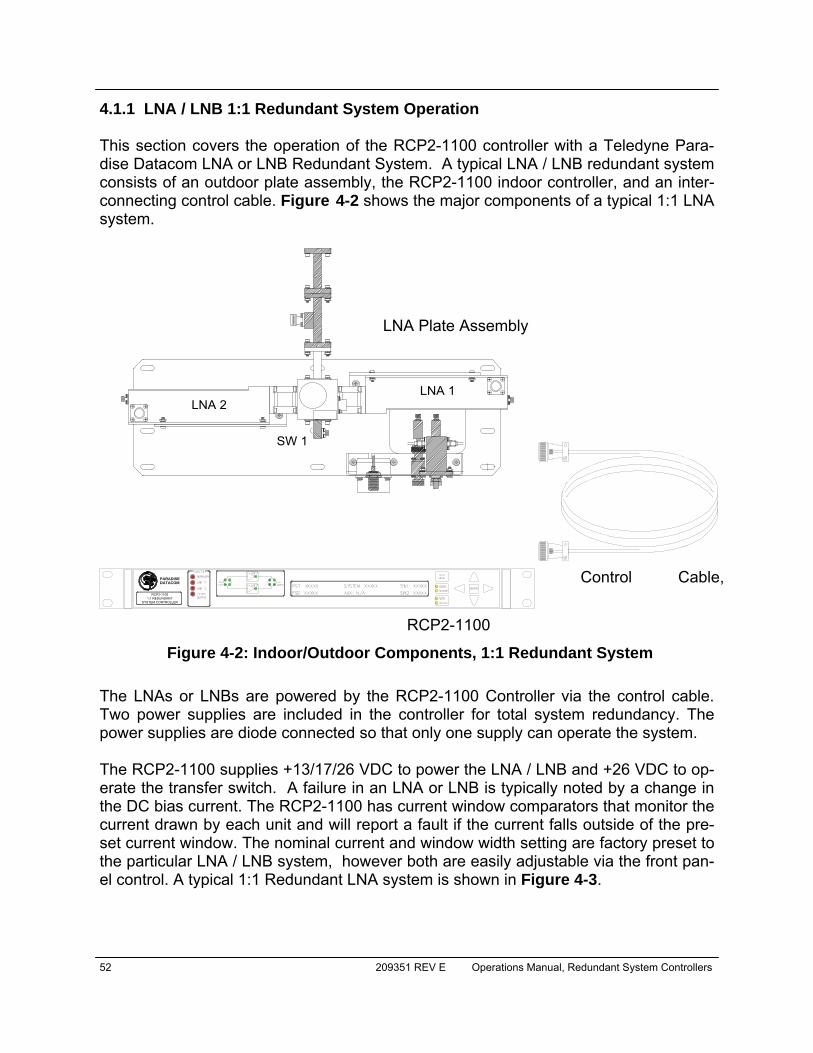
52 209351 REV E Operations Manual, Redundant System Controllers
4.1.1 LNA / LNB 1:1 Redundant System Operation This section covers the operation of the RCP2-1100 controller with a Teledyne Para-dise Datacom LNA or LNB Redundant System. A typical LNA / LNB redundant system consists of an outdoor plate assembly, the RCP2-1100 indoor controller, and an inter-connecting control cable. Figure 4-2 shows the major components of a typical 1:1 LNA system.
The LNAs or LNBs are powered by the RCP2-1100 Controller via the control cable. Two power supplies are included in the controller for total system redundancy. The power supplies are diode connected so that only one supply can operate the system. The RCP2-1100 supplies +13/17/26 VDC to power the LNA / LNB and +26 VDC to op-erate the transfer switch. A failure in an LNA or LNB is typically noted by a change in the DC bias current. The RCP2-1100 has current window comparators that monitor the current drawn by each unit and will report a fault if the current falls outside of the pre-set current window. The nominal current and window width setting are factory preset to the particular LNA / LNB system, however both are easily adjustable via the front pan-el control. A typical 1:1 Redundant LNA system is shown in Figure 4-3.
LNA 1LNA 2
SW 1
LNA Plate Assembly
Control Cable,
RCP2-1100
PARADISEDATACOM
RCP2-11001:1 REDUNDANT
SYSTEM CONTROLLER
Figure 4-2: Indoor/Outdoor Components, 1:1 Redundant System
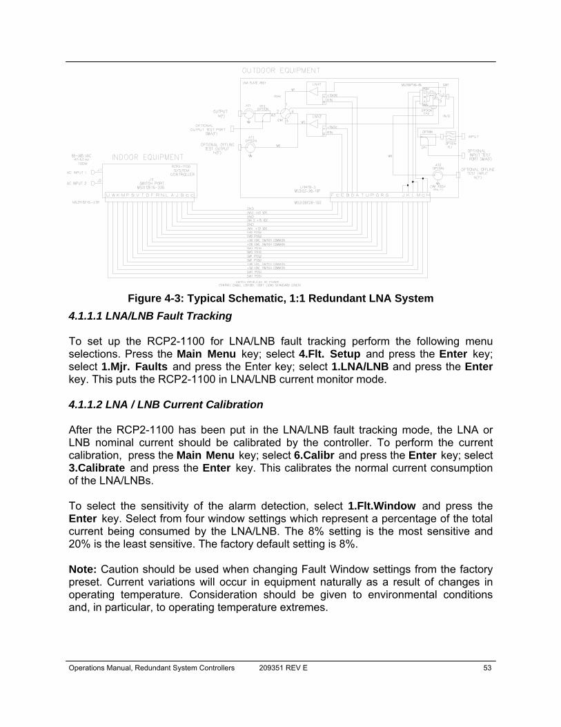
Operations Manual, Redundant System Controllers 209351 REV E 53
4.1.1.1 LNA/LNB Fault Tracking To set up the RCP2-1100 for LNA/LNB fault tracking perform the following menu selections. Press the Main Menu key; select 4.Flt. Setup and press the Enter key; select 1.Mjr. Faults and press the Enter key; select 1.LNA/LNB and press the Enter key. This puts the RCP2-1100 in LNA/LNB current monitor mode. 4.1.1.2 LNA / LNB Current Calibration After the RCP2-1100 has been put in the LNA/LNB fault tracking mode, the LNA or LNB nominal current should be calibrated by the controller. To perform the current calibration, press the Main Menu key; select 6.Calibr and press the Enter key; select 3.Calibrate and press the Enter key. This calibrates the normal current consumption of the LNA/LNBs. To select the sensitivity of the alarm detection, select 1.Flt.Window and press the Enter key. Select from four window settings which represent a percentage of the total current being consumed by the LNA/LNB. The 8% setting is the most sensitive and 20% is the least sensitive. The factory default setting is 8%. Note: Caution should be used when changing Fault Window settings from the factory preset. Current variations will occur in equipment naturally as a result of changes in operating temperature. Consideration should be given to environmental conditions and, in particular, to operating temperature extremes.
Figure 4-3: Typical Schematic, 1:1 Redundant LNA System
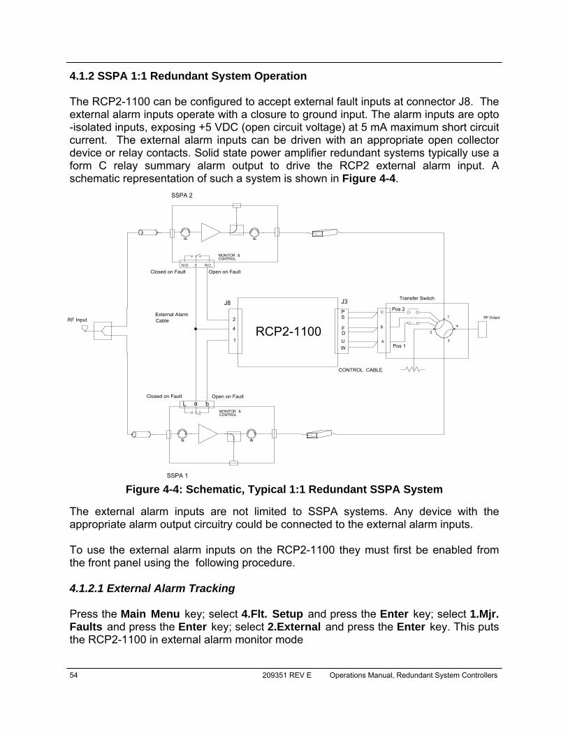
54 209351 REV E Operations Manual, Redundant System Controllers
4.1.2 SSPA 1:1 Redundant System Operation The RCP2-1100 can be configured to accept external fault inputs at connector J8. The external alarm inputs operate with a closure to ground input. The alarm inputs are opto-isolated inputs, exposing +5 VDC (open circuit voltage) at 5 mA maximum short circuit current. The external alarm inputs can be driven with an appropriate open collector device or relay contacts. Solid state power amplifier redundant systems typically use a form C relay summary alarm output to drive the RCP2 external alarm input. A schematic representation of such a system is shown in Figure 4-4.
The external alarm inputs are not limited to SSPA systems. Any device with the appropriate alarm output circuitry could be connected to the external alarm inputs. To use the external alarm inputs on the RCP2-1100 they must first be enabled from the front panel using the following procedure. 4.1.2.1 External Alarm Tracking Press the Main Menu key; select 4.Flt. Setup and press the Enter key; select 1.Mjr. Faults and press the Enter key; select 2.External and press the Enter key. This puts the RCP2-1100 in external alarm monitor mode
&CONTROLMONITOR
A
B
C1
24
3
RF Output
Transfer Switch
CONTROL CABLE
C N.C.N.O.
RCP2-1100
J8 J3
4
1
2External AlarmCableRF Input
FD
Pos 1
Pos 2
UW
PS
&CONTROLMONITOR
Open on FaultClosed on Fault
SSPA 2
SSPA 1
Closed on Fault Open on Faulta bL
Figure 4-4: Schematic, Typical 1:1 Redundant SSPA System
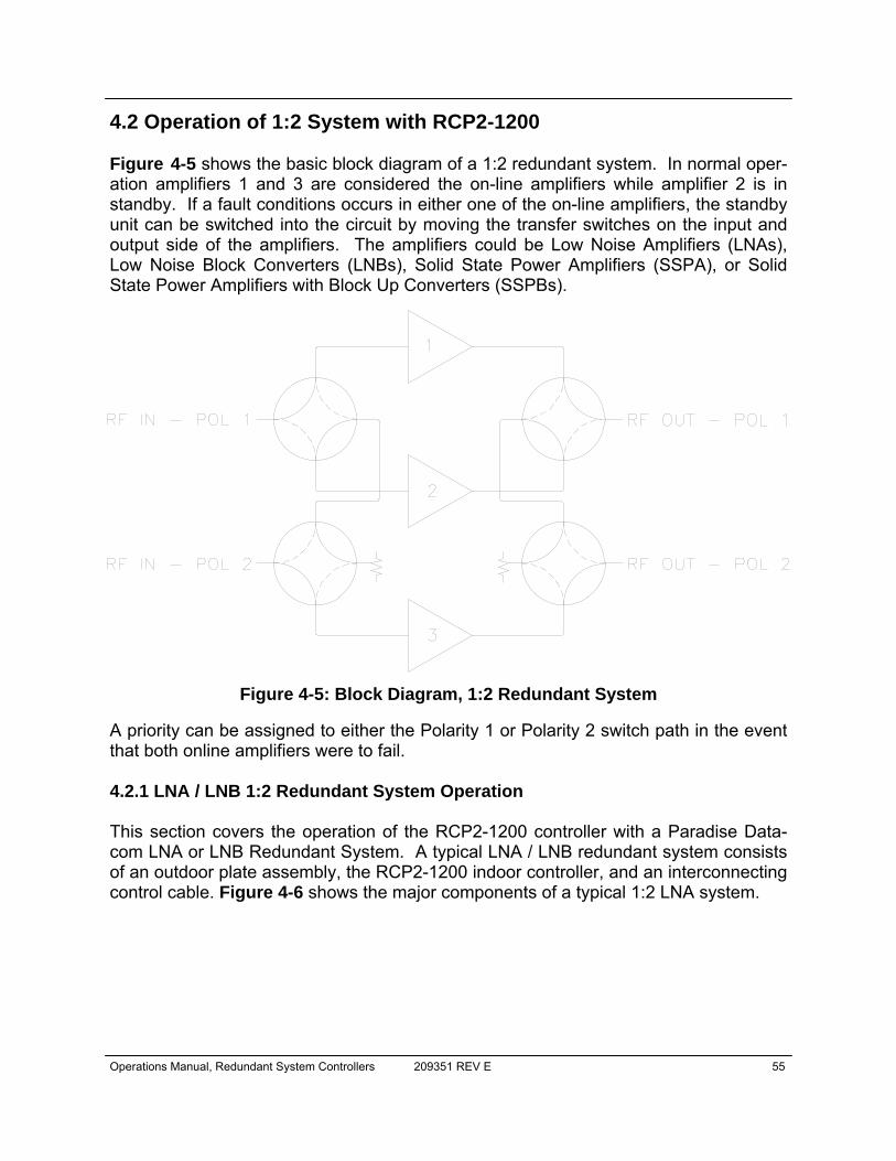
Operations Manual, Redundant System Controllers 209351 REV E 55
4.2 Operation of 1:2 System with RCP2-1200 Figure 4-5 shows the basic block diagram of a 1:2 redundant system. In normal oper-ation amplifiers 1 and 3 are considered the on-line amplifiers while amplifier 2 is in standby. If a fault conditions occurs in either one of the on-line amplifiers, the standby unit can be switched into the circuit by moving the transfer switches on the input and output side of the amplifiers. The amplifiers could be Low Noise Amplifiers (LNAs), Low Noise Block Converters (LNBs), Solid State Power Amplifiers (SSPA), or Solid State Power Amplifiers with Block Up Converters (SSPBs).
A priority can be assigned to either the Polarity 1 or Polarity 2 switch path in the event that both online amplifiers were to fail. 4.2.1 LNA / LNB 1:2 Redundant System Operation This section covers the operation of the RCP2-1200 controller with a Paradise Data-com LNA or LNB Redundant System. A typical LNA / LNB redundant system consists of an outdoor plate assembly, the RCP2-1200 indoor controller, and an interconnecting control cable. Figure 4-6 shows the major components of a typical 1:2 LNA system.
Figure 4-5: Block Diagram, 1:2 Redundant System
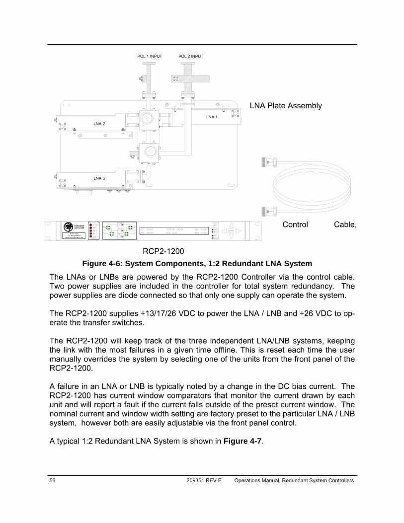
56 209351 REV E Operations Manual, Redundant System Controllers
The LNAs or LNBs are powered by the RCP2-1200 Controller via the control cable. Two power supplies are included in the controller for total system redundancy. The power supplies are diode connected so that only one supply can operate the system. The RCP2-1200 supplies +13/17/26 VDC to power the LNA / LNB and +26 VDC to op-erate the transfer switches. The RCP2-1200 will keep track of the three independent LNA/LNB systems, keeping the link with the most failures in a given time offline. This is reset each time the user manually overrides the system by selecting one of the units from the front panel of the RCP2-1200. A failure in an LNA or LNB is typically noted by a change in the DC bias current. The RCP2-1200 has current window comparators that monitor the current drawn by each unit and will report a fault if the current falls outside of the preset current window. The nominal current and window width setting are factory preset to the particular LNA / LNB system, however both are easily adjustable via the front panel control. A typical 1:2 Redundant LNA System is shown in Figure 4-7.
LNA Plate Assembly
Control Cable,
RCP2-1200
LNA 2
LNA 3
LNA 1
POL 2 INPUTPOL 1 INPUT
PARADISEDATACOM
RCP2-12001:2 REDUNDANT
SYSTEM CONTROLLER
Figure 4-6: System Components, 1:2 Redundant LNA System
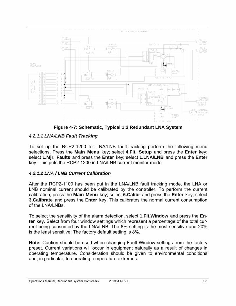
Operations Manual, Redundant System Controllers 209351 REV E 57
4.2.1.1 LNA/LNB Fault Tracking To set up the RCP2-1200 for LNA/LNB fault tracking perform the following menu selections. Press the Main Menu key; select 4.Flt. Setup and press the Enter key; select 1.Mjr. Faults and press the Enter key; select 1.LNA/LNB and press the Enter key. This puts the RCP2-1200 in LNA/LNB current monitor mode 4.2.1.2 LNA / LNB Current Calibration After the RCP2-1100 has been put in the LNA/LNB fault tracking mode, the LNA or LNB nominal current should be calibrated by the controller. To perform the current calibration, press the Main Menu key; select 6.Calibr and press the Enter key; select 3.Calibrate and press the Enter key. This calibrates the normal current consumption of the LNA/LNBs. To select the sensitivity of the alarm detection, select 1.Flt.Window and press the En-ter key. Select from four window settings which represent a percentage of the total cur-rent being consumed by the LNA/LNB. The 8% setting is the most sensitive and 20% is the least sensitive. The factory default setting is 8%. Note: Caution should be used when changing Fault Window settings from the factory preset. Current variations will occur in equipment naturally as a result of changes in operating temperature. Consideration should be given to environmental conditions and, in particular, to operating temperature extremes.
Figure 4-7: Schematic, Typical 1:2 Redundant LNA System
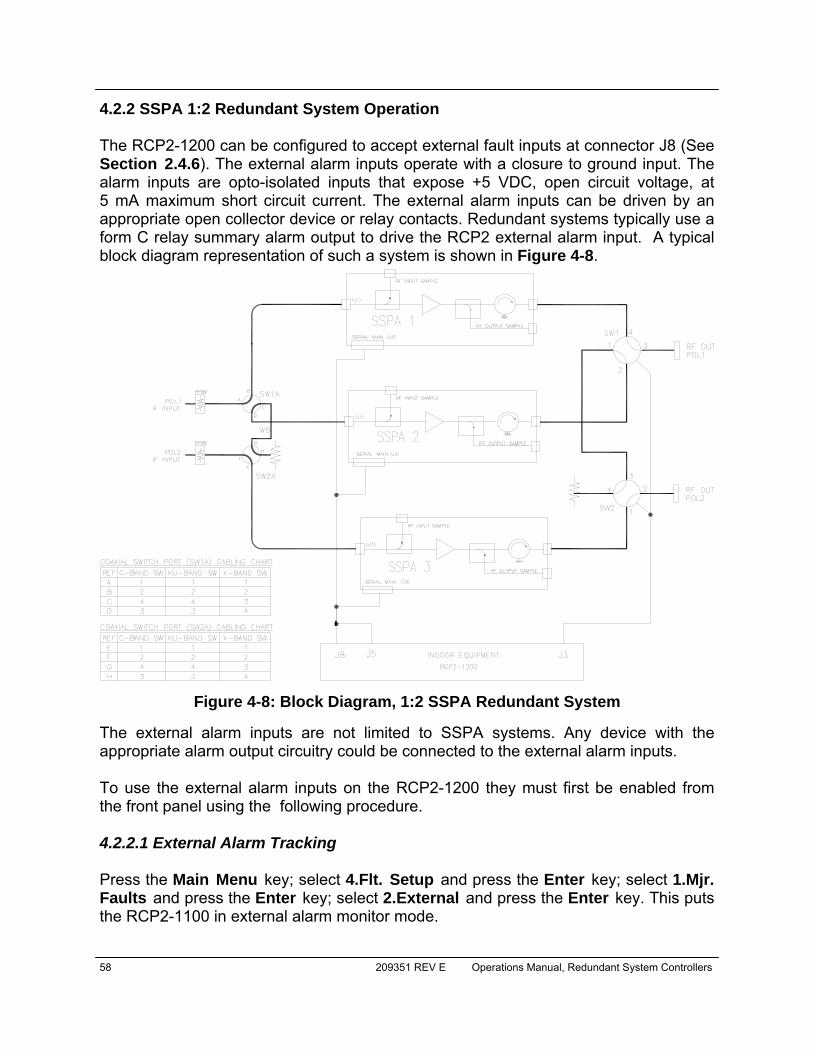
58 209351 REV E Operations Manual, Redundant System Controllers
4.2.2 SSPA 1:2 Redundant System Operation The RCP2-1200 can be configured to accept external fault inputs at connector J8 (See Section 2.4.6). The external alarm inputs operate with a closure to ground input. The alarm inputs are opto-isolated inputs that expose +5 VDC, open circuit voltage, at 5 mA maximum short circuit current. The external alarm inputs can be driven by an appropriate open collector device or relay contacts. Redundant systems typically use a form C relay summary alarm output to drive the RCP2 external alarm input. A typical block diagram representation of such a system is shown in Figure 4-8.
The external alarm inputs are not limited to SSPA systems. Any device with the appropriate alarm output circuitry could be connected to the external alarm inputs. To use the external alarm inputs on the RCP2-1200 they must first be enabled from the front panel using the following procedure. 4.2.2.1 External Alarm Tracking Press the Main Menu key; select 4.Flt. Setup and press the Enter key; select 1.Mjr. Faults and press the Enter key; select 2.External and press the Enter key. This puts the RCP2-1100 in external alarm monitor mode.
Figure 4-8: Block Diagram, 1:2 SSPA Redundant System

Operations Manual, Redundant System Controllers 209351 REV E 59
4.3 Operation of 1:1 Fixed Phase Combined System with FPRC-1100 The 1:1 Fixed Phase Combined Redundant System is a popular system architecture that enables two Solid State Power Amplifiers to operate as a normal 1:1 redundant system or a phase combined system. The basic system topology is very similar to a 1:1 redundant system and is shown in Figure 4-9. An additional switch is included which allows either amplifier to be individually routed to the antenna or connect both amplifiers to a waveguide combiner. The combined system output power is then routed to the antenna. The operation is very similar to the older generation variable phase ratio combiner (VPRC) techniques.
System designers find that the 1:1 Fixed Phase Combined Amplifier System topology is a cost effective solution to realizing higher power amplifier systems. For slightly more investment over a traditional 1:1 redundant system, the operator can have the capabil-ity of doubling the individual amplifier output power when conditions may require addi-tional power. This is helpful when either atmospheric conditions require more power or if additional satellite traffic requires higher power capacity. The FPRC-1100 controller is specifically designed to handle such an amplifier system. It not only handles all of the traditional fault monitoring and switching duties but also provides an overall system monitor and control facility. The FPRC-1100 can adjust the system gain over a 20 dB range without the need to adjust each of the amplifiers individually. It also provides a convenient display of the overall system output power. Individual amplifier monitor and control can all be achieved through the FPRC-1100 either locally via the front panel or by remote serial communication.
RF Output
Amp 1
Amp 2
RF Input
Figure 4-9: Block Diagram, 1:1 Fixed Phase Combined System
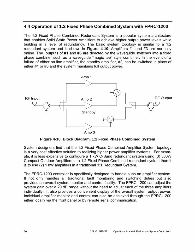
60 209351 REV E Operations Manual, Redundant System Controllers
4.4 Operation of 1:2 Fixed Phase Combined System with FPRC-1200 The 1:2 Fixed Phase Combined Redundant System is a popular system architecture that enables Solid State Power Amplifiers to achieve higher output power levels while building in a level of redundancy. The basic system topology is similar to a 1:2 redundant system and is shown in Figure 4-10. Amplifiers #1 and #3 are normally online. The outputs of #1 and #3 are directed by the waveguide switches into a fixed phase combiner such as a waveguide “magic tee” style combiner. In the event of a failure of either on line amplifier, the standby amplifier, #2, can be switched in place of either #1 or #3 and the system maintains full output power.
System designers find that the 1:2 Fixed Phase Combined Amplifier System topology is a very cost effective solution to realizing higher power amplifier systems. For exam-ple, it is less expensive to configure a 1 kW C-Band redundant system using (3) 500W Compact Outdoor Amplifiers in a 1:2 Fixed Phase Combined redundant system than it is to use (2) 1 kW amplifiers in a traditional 1:1 Redundant System. The FPRC-1200 controller is specifically designed to handle such an amplifier system. It not only handles all traditional fault monitoring and switching duties but also provides an overall system monitor and control facility. The FPRC-1200 can adjust the system gain over a 20 dB range without the need to adjust each of the three amplifiers individually. It also provides a convenient display of the overall system output power. Individual amplifier monitor and control can also be achieved through the FPRC-1200 either locally via the front panel or by remote serial communication.
RF Input
Amp 1
Amp 2
Standby
Amp 3
RF Output
Figure 4-10: Block Diagram, 1:2 Fixed Phase Combined System
Operations Manual, Redundant System Controllers 209351 REV E 61
4.5 RCP Remote Control of System SSPAs RCP units that meet certain conditions are capable of remote control of system SSPAs through the RCP Local Serial Port (J5).
Note: The following features are supported only with firmware version 2.2.00 and above. To verify your unit firmware version browse to the SysID screen on the front panel. If the firmware version is below 2.2.00, the unit’s firmware can be upgraded to the proper version by the user.
Systems may contain up to three amplifiers (consisting of the Teledyne Paradise Datacom Compact Outdoor, Rack Mount SSPAs, or vBUC amplifiers) and a remote RF Power Meter. The SSPAs and RF Power Meter must be connected to the RCP Local Serial Port (J5) via RS485 4-wire or 2-wire interface. All connected components must utilize Teledyne Paradise Datacom String Serial Protocol at 9600 Baud. If properly configured, the RCP will allow the user to remotely change the Mute Status and Attenuation Level of the connected units, and monitor the Output RF Power. Under such control, all connected units are exclusively controlled by the RCP unit and any new unit added to the system will be automatically adjusted to the selected Attenuation Level and Mute State. Units equipped with firmware version 3.30 or later have extended remote system moni-toring features, including the ability to monitor and display individual unit temperature and ambient temperature (if the system is equipped with a Teledyne Paradise Data-com remote RF Power Meter). Moreover, the unit has an additional option to mute a sub-system during the period of switchover (see Section 3.3.5.8).
Note: The SSPA fault status is not controlled via the serial line, therefore all controlled SSPA summary alarm lines still have to be connected to the RCP External Alarms Port (J8). A Teledyne Paradise Datacom Remote RF Power Meter can be powered up either from the RCP unit (when re-mote control mode is enabled, the RCP will automatically turn on its LNA/LNB Power supplies) or from an external DC power source with the fol-lowing characteristics: Output voltage +13/17/26V; Minimum Output Cur-rent 300 mA.
Starting with RCP firmware version 3.40, the RCP supports External Reflected Power Monitoring. Monitor unit supports measurement of overall system Reflected Power within 20 dBm range with +/-1 dBm accuracy. The current value of the Reflected power can be viewed on the first informative screen of subsystem menus or accessed through the remote control interface. Outside of specified range, the accuracy of meas-urement is not guaranteed. If the supplied system is not equipped with this feature, the monitor value of reflected power on the front panel VFD will indicated as “N/A”.

62 209351 REV E Operations Manual, Redundant System Controllers
4.5.1 Configuring the RCP for Remote Control Mode The RCP unit has to be configured to support remote control of the system. To do so, perform the following steps:
1.Press the Main Menu key on the RCP front panel; 2.Select 5.Options and press the Enter key; 3.Select 6.More and press the Enter key; 4.Select 3.SSPA and press the Enter key; 5.Select 3.System Type and press the Enter key; 6.Select 2.RM SSPA if you want to control a system of Rack Mount SSPAs,
Select 3.CO SSPA if you want to control a system of Compact Outdoor SSPAs, or Select 4.vBUC if you want to control a system of vBUC amplifi-ers, then press the Enter key. To disable the remote control feature, select 1.None and press the Enter key;
7.Select 4.View and press the Enter key; Your RCP unit is now ready to control a remote system. After the RCP unit is config-ured to control a remote system, make sure the system is correctly wired. See Tables 4-1, 4-2 and 4-3 for proper wiring.
RCP2 J5 Serial Local SSPA1 M&C J4* SSPA2 M&C J4 SSPA3 M&C J4
1,9 (RX+; 120 Ohm Termination) T (TX+) T (TX+) T (TX+)
2 (RX-) E (TX-) E (TX-) E (TX-)
3 (TX-) F (RX-) F (RX-) F (RX-)
4 (TX+) U (RX+) U (RX+) U (RX+)
5 (Ground) B,V (Mute In, GND) B,V (Mute In, GND) B,V (Mute In, GND)
RCP2 J8 Ext. Alarm SSPA1 M&C J4 SSPA2 M&C J4 SSPA3 M&C J4
1 (Ext. Alarm 1) b (Summary open on fault)
2 (Ext. Alarm 2) b (Summary open on fault)
3 (Ext. Alarm 3) b (Summary open on fault)
4 (Ground) a (Summary Common)
a (Summary Common)
a (Summary Common)
* If the cable length exceeds 50 ft., a termination resistor of 120 Ohms must be installed between F and U of the SSPA1 M&C J4 connector.
Table 4-1: Compact Outdoor SSPA Wiring
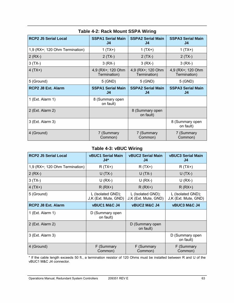
Operations Manual, Redundant System Controllers 209351 REV E 63
RCP2 J5 Serial Local SSPA1 Serial Main J4
SSPA2 Serial Main J4
SSPA3 Serial Main J4
1,9 (RX+; 120 Ohm Termination) 1 (TX+) 1 (TX+) 1 (TX+)
2 (RX-) 2 (TX-) 2 (TX-) 2 (TX-)
3 (TX-) 3 (RX-) 3 (RX-) 3 (RX-)
4 (TX+) 4,9 (RX+; 120 Ohm Termination)
4,9 (RX+; 120 Ohm Termination)
4,9 (RX+; 120 Ohm Termination)
5 (Ground) 5 (GND) 5 (GND) 5 (GND)
RCP2 J8 Ext. Alarm SSPA1 Serial Main J4
SSPA2 Serial Main J4
SSPA3 Serial Main J4
1 (Ext. Alarm 1) 8 (Summary open on fault)
2 (Ext. Alarm 2) 8 (Summary open on fault)
3 (Ext. Alarm 3) 8 (Summary open on fault)
4 (Ground) 7 (Summary Common)
7 (Summary Common)
7 (Summary Common)
Table 4-2: Rack Mount SSPA Wiring
Table 4-3: vBUC Wiring RCP2 J5 Serial Local vBUC1 Serial Main
J4* vBUC2 Serial Main
J4 vBUC3 Serial Main
J4
1,9 (RX+; 120 Ohm Termination) R (TX+) R (TX+) R (TX+)
2 (RX-) U (TX-) U (TX-) U (TX-)
3 (TX-) U (RX-) U (RX-) U (RX-)
4 (TX+) R (RX+) R (RX+) R (RX+)
5 (Ground) L (Isolated GND); J,K (Ext. Mute, GND)
L (Isolated GND); J,K (Ext. Mute, GND)
L (Isolated GND); J,K (Ext. Mute, GND)
RCP2 J8 Ext. Alarm vBUC1 M&C J4 vBUC2 M&C J4 vBUC3 M&C J4
1 (Ext. Alarm 1) D (Summary open on fault)
2 (Ext. Alarm 2) D (Summary open on fault)
3 (Ext. Alarm 3) D (Summary open on fault)
4 (Ground) F (Summary Common)
F (Summary Common)
F (Summary Common)
* If the cable length exceeds 50 ft., a termination resistor of 120 Ohms must be installed between R and U of the vBUC1 M&C J4 connector.
64 209351 REV E Operations Manual, Redundant System Controllers
All attached units must be properly configured in order to work under RCP Remote Control. The following parameters must be set for each unit:
1. Serial Protocol to “Normal” or “String”; 2. Selected Baud Rate to 9600; 3. Type of Serial Interface to “RS485”; 4. Unique address selected as follows:
A.SSPA1=1; B.SSPA2=2; C.SSPA3=3 D.Remote RF Power Meter=4.
4.5.2 Controlling PowerMAX Systems Starting with firmware version 6.00, the controller has the capability to remotely control PowerMAX systems. The unit is capable of simultaneous control of three independent PowerMAX systems. Each PowerMAX system must be configured for Floating Master Mode (for details on this mode, see the PowerMAX manual). As with control over an individual HPA, PowerMAX systems have to be configured for a specific Master response serial address: 1, 2 and 3. Unique HPA chassis in the sys-tem must be set outside of the control address range. Recommended addressing for individual chassis are: 11 to 18 for the first system; 21 to 28 for the second; and 31 to 38 for the third. Each PowerMAX system will be viewed as single HPA unit and top level parameters will be monitored by the controller. PowerMAX is essentially a N+1 redundancy system where any HPA chassis can per-form the master controller functions. In order for the controller to automatically connect to the current master unit, a RS-485 connection to all HPAs in the connected systems must be provided. Since the total number of connected units may reach 24 units, care must be observed when the RS-485 network is laid out. Racks need to be daisy chained with 4-wire twist-ed pair cable and line termination enabled only on the farthest RS-485 node. PowerMAX control mode is different from regular RM SSPA, therefore selection of the appropriate mode from remote control system selection is important.
1. Press the Main Menu key on the RCP front panel; 2. Select 5.Options and press the Enter key; 3. Select 6.More and press the Enter key; 4. Select 3.SSPA and press the Enter key; 5. Select 3.System Type and press the Enter key; 6. Select 6.PMax then press the Enter key.
Operations Manual, Redundant System Controllers 209351 REV E 65
4.5.2 Using M&C Features of RCP to Control a SSPA System All SSPA control-related functions are grouped on the same menu, the SSPA control menu. To access the SSPA control menu, perform the following sequence on the RCP front panel:
1. Press the Main Menu key; 2. Select 5.Options and press the Enter key; 3. Select 6.More and press the Enter key; 4. Select 2.SSPA Ctrl and press the Enter key.
The SSPA control menu will be displayed on the front panel VFD as follows: 1.SSPA Info 3.Mute 5.More 2.Attenuation 4.Units All of the following steps describe RCP remote operation of an SSPA, and assume the user has already selected the SSPA control menu. 4.5.2.1 Change Mute State To change the overall mute state of a controlled SSPA system from the RCP, perform the following steps:
1. Select 3.Mute and press the Enter key; 2. Select desired Mute state and press the Enter key;
4.5.2.2 Change Attenuation Level To change the overall attenuation level of a controlled SSPA system from the RCP, perform the following steps:
1. Select 2.Attenuation and press the Enter key; 2. Select the desired level of attenuation and press the Enter key;
4.5.2.3 Change Switch Mute Option Value The following option was introduced into the RCP control setup to overcome a problem with microwave arcing, which may potentially damage a switching component if switching RF power exceeds 400 Watts. This particular problem becomes a critical issue if coaxial RF pass switches are used. In general, all Teledyne Paradise Datacom SSPAs are well protected against high reflected power conditions which may take place during output microwave switchover. But with certainty, waveguide or coaxial switches will develop an internal electrical arc during switchover if the output power is significant. Such conditions, will not lead to

66 209351 REV E Operations Manual, Redundant System Controllers
instant failure, but over time may diminish some critical RF switch characteristics. If this option is enabled, the system ability to output RF power will be bonded to the switch position sensing circuitry. This circuitry consists of the following components: a RCP electronic switch position detector; a wiring harness between the RCP and RF switch; and RF switch position sensors. Failure of the above components will lead to break in transmission.
Paradise Datacom LLC strongly recommends not to enable this op-tion unless absolutely necessary.
Note: In order to enable switch muting, the system sub type must be se-lected to either CO SSPA, RM SSPA or vBUC! If the system type set to “None,” the switch muting setting will be inhibited.
There are four selections under this option: No muting (“1.SWMute OFF”); internal muting (“2.Internal On”); external muting (“3.External On”) or all switch muting is on (“4.All ON”). Internal muting refers to the particular RCP unit itself. If the position of one of the controlled RF switches changes or is about to change, the RCP will mute the SSPA subsystem by issuing a special “mute command” over the RS485 serial interface. When the RF switch position indicator detects that the switch reliably reached Posi-tion1 or Position2, a “Mute Off” command will be issued to the SSPA subsystem over the serial interface. If the switch gets stuck between positions, the system will remain muted until the situation is resolved or the Switch Mute option is turned off. 4.5.2.4 Units This option allows the user to select the RF Power measurement units (measured in either dBm or Watts) reported on the front panel and remote interface. Both Forward and Reflected RF power sensor measurements will be affected.
Operations Manual, Redundant System Controllers 209351 REV E 67
4.6 View SSPA System Info To verify a selection on the SSPA control menu, select 4.View and press the Enter key. The selected attenuation, forward RF power level, system mute state and type of the selected system will be displayed on the front panel VFD.
Note: The Forward RF Power Level can be displayed only if a Teledyne Paradise Datacom remote RF Power Meter was included in the system. Otherwise, this item will display “N/A” for not available.
SSPA sub system info page 1 pertains to conditions and settings common to all SSPAs in a subsystem (RCP firmware version 3.10 or better). Atten.(dB) is the current level of subsystem attenuation. All SSPAs in the system are adjusted simultaneously and have same level of attenuation. Mute – Indicates the overall mute state of the subsystem. Mute state is applied to all connected SSPAs, the mute state of an individual SSPA can’t be different then the system mute state. FrwrdRF(Watts/dBm) – System forward RF power detector readout (if equipped). The readout can be represented in Watts or dBms. If the subsystem is not equipped with this power detector, the readout will display N/A. Ref.RF(Watts/dBm) (RCP firmware version 3.40 or better) – Readout from system reflected RF power detector (if equipped). The readout can be represented in Watts or dBms. (see Units menu selection). If the subsystem is not equipped with this power detector, readout will display N/A. SSPA sub system info page 2 (RCP firmware version 3.60 or better) pertains to individual SSPA output power levels. UnitRFx(dBm) – The forward RF output level of each individual SSPA. The readout can be represented in dBms only. The value of an individual forward RF power is measured on the output flange of a particular SSPA. If the SSPA unit is not present in the system, readout will indicate N/A.
Important! Real system output power most likely will be different from this parameter. In 1:1 or 1:2 systems, losses in switching and waveguide systems are not accounted. In phase combined systems, real output power will depend on the combining configuration. For system output power, refer to FrwrdRF(Watts/dBm) on SSPA subsystem info page 1.
SSPA sub system info page 3 (RCP firmware version 3.10 or better) pertains to each individual SSPA unit’s core temperature and ambient temperature.
68 209351 REV E Operations Manual, Redundant System Controllers
Ambient(C) – ambient temperature readout in °C. This readout is available only on the systems equipped with forward RF power sensor, otherwise it will indicate N/A. Unitx(C) – is an individual SSPA unit’s core temperature in °C. If a unit is not present in the current system configuration, value will read N/A. SSPA sub system info page 4 (RCP firmware version 3.60 or better) pertains to individual SSPA unit’s DC current consumption. UnitDCx(Amp) – DC current consumption of a SSPA unit, measured in Amperes. If a unit is not present in the current system configuration, value will read N/A. SSPA sub system info page 5 (RCP firmware version 3.30 or better) pertains to additional subsystem settings. System Type – is the type of connected SSPA subsystem. Possible readout: Compact – for subsystem of Compact Outdoor SSPAs; RM – for subsystem of Rack Mount SSPAs; and vBUC – for subsystem of vBUC amplifiers. SWMute – is type of switch muting implemented on the current system. Off – no switch muting; External – for external switch muting input; Internal – for switching associated with this RCP unit; Both – utilization of switch muting inputs.
Operations Manual, Redundant System Controllers 209351 REV E 69
4.7 Advanced System Level Troubleshooting with RCP The RCP controller offers the ability to control various systems, which can include various subcomponents. In some cases it is important to quickly pinpoint a faulty component without system disintegration. The RCP controller offers such capabilities. The following section describes the troubleshooting procedure for some systems.
4.7.1 Scenario 1
A 1:2 system contains devices connected to the RCP external port (SSPA) as well as an array of LNA devices connected to the Plate assembly port. Major faults are configured to track both types of fault. Fault logic is set to “High”. The RCP indicates a Unit1 fault. To determine which component of the controlled setup is failed, scroll down to System Info Page 4 and verify the status of the “LNA faults” and “SSPA faults” items. One or both items should indicate “1----”. If the faulted element is found in the LNA setup, the user can double-check what caused it. Perform the following steps: Press the Main Menu key; select 6.Calibration and press the Enter key; select 4.View CalPoints and press the Enter key. The VFD will display the advanced LNA/LNB debugging screen, which will show calibration points and current consumption for each LNA. Note the difference between the “LNA1(mA)” and “Cal1(mA)” values displayed on the screen. If the faulted element is found in the SSPA setup, double-check the fault causing the problem by selecting Info page 5. Note the state of the “ExtFaults” item, which should indicate “Aux-111 HPA001”. This explains why unit 1 was considered as faulted (note logic “high” state “1” in “HPA001 “).
4.7.2 Scenario 2 In a 1:2 SSPA system with 5 auxiliary devices connected to the RCP external faults port, the RCP utilizes “fault on high” logic. Auxiliary faults are enabled. An auxiliary fault indicates “Fault” condition. To find which auxiliary line indicates fault, browse to Info page 5. Note the value of “ExtFaults” item. AUX-[Unit 3][Unit 2][Unit 1], where the “#” in “Unit #” is either “1” or “0”. A “0” indicates a fault and “1” indicates no fault. So if the value shown on the display is “AUX-011 HPA000”, that indicates a fault state for auxiliary devices connected to auxiliary port lines 2 and 1.

70 209351 REV E Operations Manual, Redundant System Controllers
THIS PAGE LEFT INTENTIONALLY BLANK

Operations Manual, Redundant System Controllers 209351 REV E 71
5.0 Design Philosophy The RCP series of redundant controllers was designed to achieve a new level in high reliability, maintenance free operation. A tightly integrated modular assembly approach has been used to realize an extremely versatile controller while maintaining its user friendly operator interface. Five basic building blocks are combined in the RCP redundant controller:
1. Redundant Power Supplies 2. Digital Core Board Assembly 3. I/O Board Assembly 4. Vacuum Fluorescent Display 5. Front Panel Mimic Display
5.0.1 Redundant Power Supplies A block diagram of the controller is shown in Figure 5-1. Two power supplies are provided in the controller. These supplies can be connected to two independent AC sources for absolute system redundancy. Either supply is capable of operating the controller and its associated transfer switches. Both power supplies have universal input capability operating over an input voltage range of 85 to 265 VAC and line frequencies of 47 to 63 Hz. The power supplies have a power factor of 0.93 ensuring minimum line harmonic products. Each power supply produces +26 VDC. The RCP2 provides three channel power outputs for connecting external LNA/LNB units. In standard configuration, each LNA/LNB channel can be selected to supply 13V or 17V with up to 900 mA DC current output. Output voltage is user-selectable either from the front panel menu or over the remote control interface. The -HP model provides an additional 24V 1500 mA output option for use with higher power external equipment. All channels are protected from overload and will reduce output if the maximum power output capacity is exceeded by an external load.
Note for 24V 1500 mA channel output: In order to provide an equal load to both internal AC/DC supplies, channels derive their power asym-metrically: Channel 1 from PS2, Channel 3 from PS1; and Channel 2 from either PS2 or PS1. See Figure 5-1. This configuration allows default standby Channel 2 to power up in case one of the AC/DC power supplies fails. In order to conserve power from the remaining power supply, the LNA/LNB channel will reduce its power output to 13V, 900 mA.
Section 5: Theory of Operation
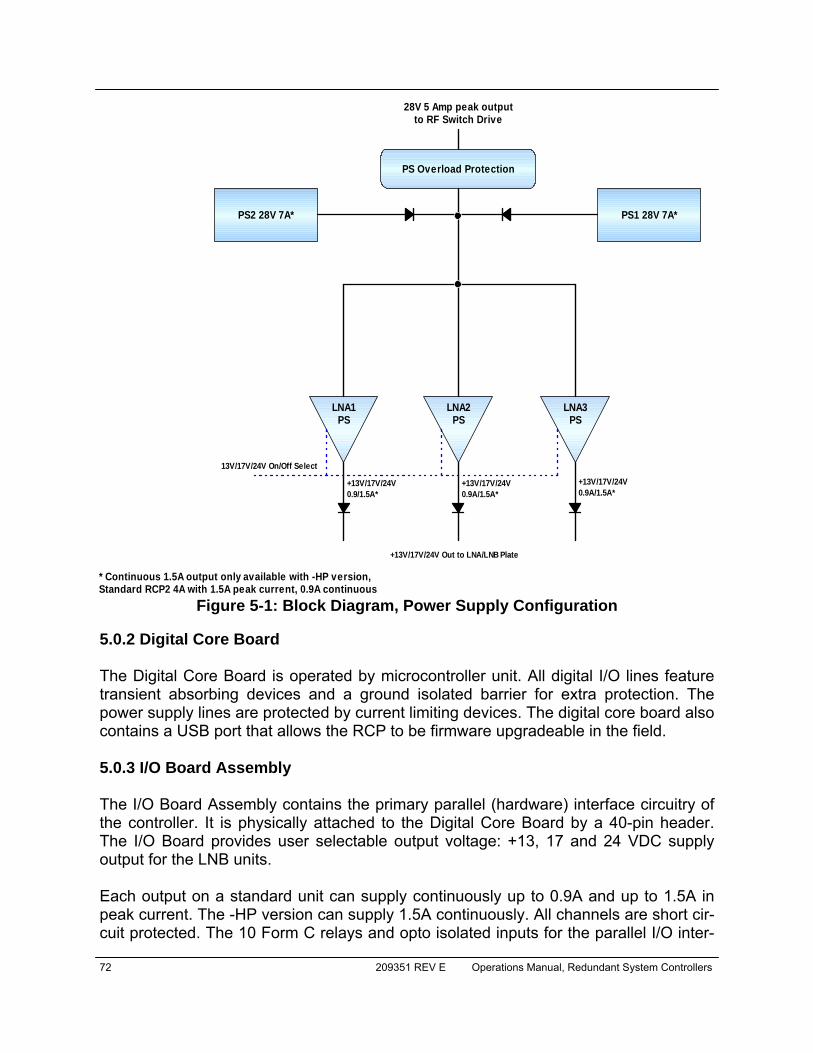
72 209351 REV E Operations Manual, Redundant System Controllers
5.0.2 Digital Core Board The Digital Core Board is operated by microcontroller unit. All digital I/O lines feature transient absorbing devices and a ground isolated barrier for extra protection. The power supply lines are protected by current limiting devices. The digital core board also contains a USB port that allows the RCP to be firmware upgradeable in the field. 5.0.3 I/O Board Assembly The I/O Board Assembly contains the primary parallel (hardware) interface circuitry of the controller. It is physically attached to the Digital Core Board by a 40-pin header. The I/O Board provides user selectable output voltage: +13, 17 and 24 VDC supply output for the LNB units. Each output on a standard unit can supply continuously up to 0.9A and up to 1.5A in peak current. The -HP version can supply 1.5A continuously. All channels are short cir-cuit protected. The 10 Form C relays and opto isolated inputs for the parallel I/O inter-
Figure 5-1: Block Diagram, Power Supply Configuration
PS Overload Protection
PS2 28V 7A* PS1 28V 7A*
LNA1PS
LNA2PS
LNA3PS
28V 5 Amp peak outputto RF Switch Drive
13V/17V/24V On/Off Select
+13V/17V/24V0.9/1.5A*
+13V/17V/24V0.9A/1.5A*
+13V/17V/24V0.9A/1.5A*
+13V/17V/24V Out to LNA/LNB Plate
* Continuous 1.5A output only available with -HP version,Standard RCP2 4A with 1.5A peak current, 0.9A continuous

Operations Manual, Redundant System Controllers 209351 REV E 73
face are included on this board assembly. A series of rugged N-channel enhancement mode MOSFET devices provide the current sink circuitry to drive either one or two waveguide transfer switches. 5.0.4 Vacuum Fluorescent Display Rarely found in redundant controllers, the RCP provides a large 2 line by 40 character alphanumeric display. This provides an extremely user friendly interface. The VFD is directly interfaced to the microcontroller via the address and data bus. Virtually all of the controller’s setup and adjustments are accessible from the VFD display. There is no need to access the interior of the controller to make any setup changes. 5.0.5 Front Panel Mimic Display The front panel display is a densely integrated array of LEDs and switches that comprise an important part of the user friendly interface. A great deal of human engineering has gone into the design of this membrane panel. A full complement of alarm indicators are provided along with the mimic display which shows the switch positions of the redundant system. Four separate navigation keys along with a sepa-rate Enter key allow the user to easily navigate the firmware menu on the Vacuum Flu-orescent Display. Separate keys have been provided for frequently used functions, fur-ther enhancing the controller’s ease of use.
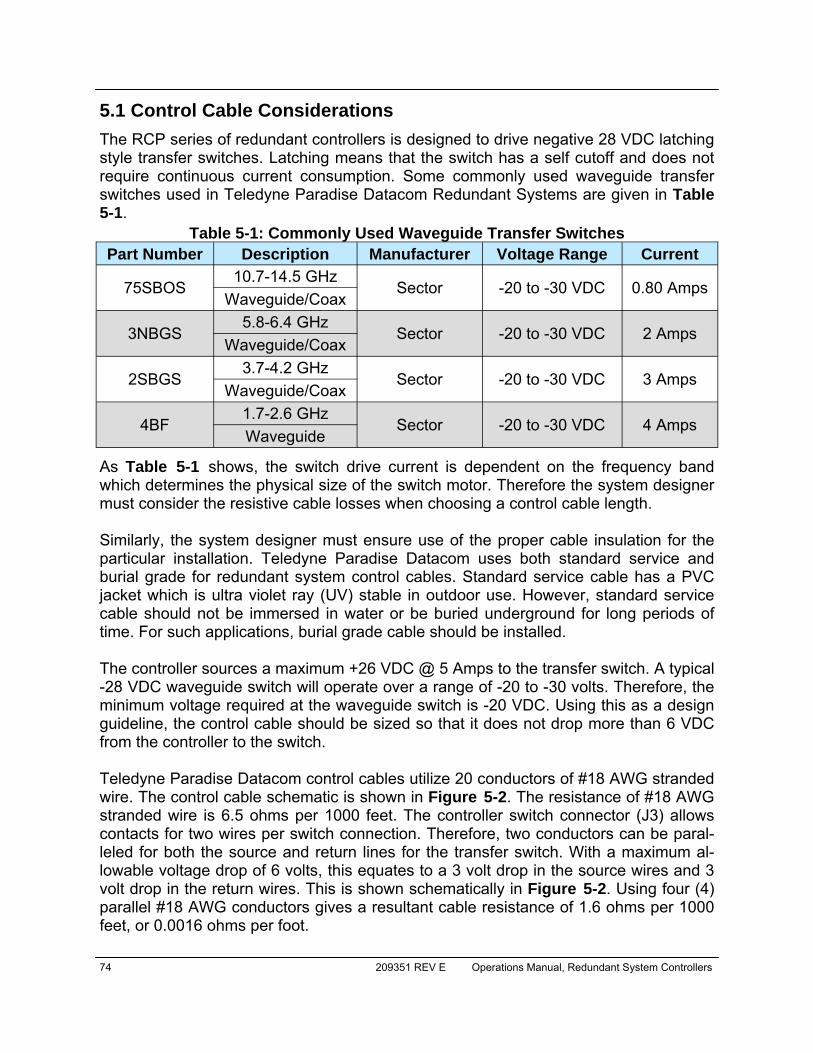
74 209351 REV E Operations Manual, Redundant System Controllers
5.1 Control Cable Considerations
The RCP series of redundant controllers is designed to drive negative 28 VDC latching style transfer switches. Latching means that the switch has a self cutoff and does not require continuous current consumption. Some commonly used waveguide transfer switches used in Teledyne Paradise Datacom Redundant Systems are given in Table 5-1.
As Table 5-1 shows, the switch drive current is dependent on the frequency band which determines the physical size of the switch motor. Therefore the system designer must consider the resistive cable losses when choosing a control cable length. Similarly, the system designer must ensure use of the proper cable insulation for the particular installation. Teledyne Paradise Datacom uses both standard service and burial grade for redundant system control cables. Standard service cable has a PVC jacket which is ultra violet ray (UV) stable in outdoor use. However, standard service cable should not be immersed in water or be buried underground for long periods of time. For such applications, burial grade cable should be installed. The controller sources a maximum +26 VDC @ 5 Amps to the transfer switch. A typical -28 VDC waveguide switch will operate over a range of -20 to -30 volts. Therefore, the minimum voltage required at the waveguide switch is -20 VDC. Using this as a design guideline, the control cable should be sized so that it does not drop more than 6 VDC from the controller to the switch. Teledyne Paradise Datacom control cables utilize 20 conductors of #18 AWG stranded wire. The control cable schematic is shown in Figure 5-2. The resistance of #18 AWG stranded wire is 6.5 ohms per 1000 feet. The controller switch connector (J3) allows contacts for two wires per switch connection. Therefore, two conductors can be paral-leled for both the source and return lines for the transfer switch. With a maximum al-lowable voltage drop of 6 volts, this equates to a 3 volt drop in the source wires and 3 volt drop in the return wires. This is shown schematically in Figure 5-2. Using four (4) parallel #18 AWG conductors gives a resultant cable resistance of 1.6 ohms per 1000 feet, or 0.0016 ohms per foot.
Part Number Description Manufacturer Voltage Range Current
75SBOS 10.7-14.5 GHz
Sector -20 to -30 VDC 0.80 Amps Waveguide/Coax
3NBGS 5.8-6.4 GHz
Sector -20 to -30 VDC 2 Amps Waveguide/Coax
2SBGS 3.7-4.2 GHz
Sector -20 to -30 VDC 3 Amps Waveguide/Coax
4BF 1.7-2.6 GHz
Sector -20 to -30 VDC 4 Amps Waveguide
Table 5-1: Commonly Used Waveguide Transfer Switches
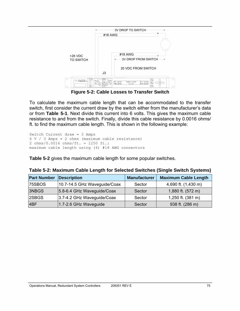
Operations Manual, Redundant System Controllers 209351 REV E 75
To calculate the maximum cable length that can be accommodated to the transfer switch, first consider the current draw by the switch either from the manufacturer’s data or from Table 5-1. Next divide this current into 6 volts. This gives the maximum cable resistance to and from the switch. Finally, divide this cable resistance by 0.0016 ohms/ft. to find the maximum cable length. This is shown in the following example: Switch Current draw = 3 Amps 6 V / 3 Amps = 2 ohms (maximum cable resistance) 2 ohms/0.0016 ohms/ft. = 1250 ft.; maximum cable length using (4) #18 AWG connectors
Table 5-2 gives the maximum cable length for some popular switches.
Figure 5-2: Cable Losses to Transfer Switch
+26 VDCTO SWITCH
20 VDC FROM SWITCHJ3
#18 AWG3V DROP TO SWITCH
#18 AWG3V DROP FROM SWITCH
Part Number Description Manufacturer Maximum Cable Length 75SBOS 10.7-14.5 GHz Waveguide/Coax Sector 4,690 ft. (1,430 m) 3NBGS 5.8-6.4 GHz Waveguide/Coax Sector 1,880 ft. (572 m) 2SBGS 3.7-4.2 GHz Waveguide/Coax Sector 1,250 ft. (381 m) 4BF 1.7-2.6 GHz Waveguide Sector 938 ft. (286 m)
Table 5-2: Maximum Cable Length for Selected Switches (Single Switch Systems)

76 209351 REV E Operations Manual, Redundant System Controllers
THIS PAGE LEFT INTENTIONALLY BLANK
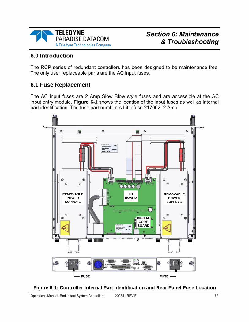
Operations Manual, Redundant System Controllers 209351 REV E 77
6.0 Introduction The RCP series of redundant controllers has been designed to be maintenance free. The only user replaceable parts are the AC input fuses. 6.1 Fuse Replacement The AC input fuses are 2 Amp Slow Blow style fuses and are accessible at the AC input entry module. Figure 6-1 shows the location of the input fuses as well as internal part identification. The fuse part number is Littlefuse 217002, 2 Amp.
Section 6: Maintenance & Troubleshooting
Figure 6-1: Controller Internal Part Identification and Rear Panel Fuse Location
FUSE FUSE
REMOVABLE POWER
SUPPLY 1
I/O BOARD
DIGITAL CORE
BOARD
REMOVABLE POWER
SUPPLY 2

78 209351 REV E Operations Manual, Redundant System Controllers
6.2 Firmware Programming Teledyne Paradise Datacom’s digital engineers continually strive to improve the perfor-mance of RCP2 software and firmware. As this occurs, software and firmware up-grades are made available. The DigiCore5 controller board allows two methods for upgrading the unit firmware:
• Upgrade over HTTP link by using web browser; • Over programming USB connector J1;
The web upgrade is performed over the RCP2 IP port and does not require any special software. It can be performed through any suitable web browser. Upgrade over the USB port requires the installation of specific hardware USB drivers and batch scripts. 6.2.1 Required Hardware The following equipment/hardware is necessary to perform the firmware upgrade.
• Depending on type of upgrade: Win7/XP PC with USB port or PC with available 10/100 Base-T port;
• Mini USB cable or Ethernet patch cable; 6.2.2 Required Software For web upgrade:
• Web browser (IE, Chrome or Firefox); For USB upgrade:
• USB FTDI VCP drivers. Drivers need to be installed before making a con-nection between the PC and the SSPA USB programming port. Visit the FTDI web page (http://www.ftdichip.com/Drivers/VCP.htm) for the latest set of virtual COM port (VCP) drivers.
• RCP2 field programing utility. Contact Teledyne Paradise Datacom tech-nical support to obtain the latest version. The Field Programming utility is typically not required for installation.
• Firmware image upgrade file: code.bin.
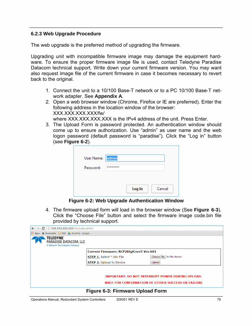
Operations Manual, Redundant System Controllers 209351 REV E 79
6.2.3 Web Upgrade Procedure The web upgrade is the preferred method of upgrading the firmware. Upgrading unit with incompatible firmware image may damage the equipment hard-ware. To ensure the proper firmware image file is used, contact Teledyne Paradise Datacom technical support. Write down your current firmware version. You may want also request image file of the current firmware in case it becomes necessary to revert back to the original.
1. Connect the unit to a 10/100 Base-T network or to a PC 10/100 Base-T net-work adapter. See Appendix A.
2. Open a web browser window (Chrome, Firefox or IE are preferred). Enter the following address in the location window of the browser: XXX.XXX.XXX.XXX/fw/ where XXX.XXX.XXX.XXX is the IPv4 address of the unit. Press Enter.
3. The Upload Form is password protected. An authentication window should come up to ensure authorization. Use “admin” as user name and the web logon password (default password is “paradise”). Click the “Log in” button (see Figure 6-2).
4. The firmware upload form will load in the browser window (See Figure 6-3). Click the “Choose File” button and select the firmware image code.bin file provided by technical support.
Figure 6-2: Web Upgrade Authentication Window
Figure 6-3: Firmware Upload Form
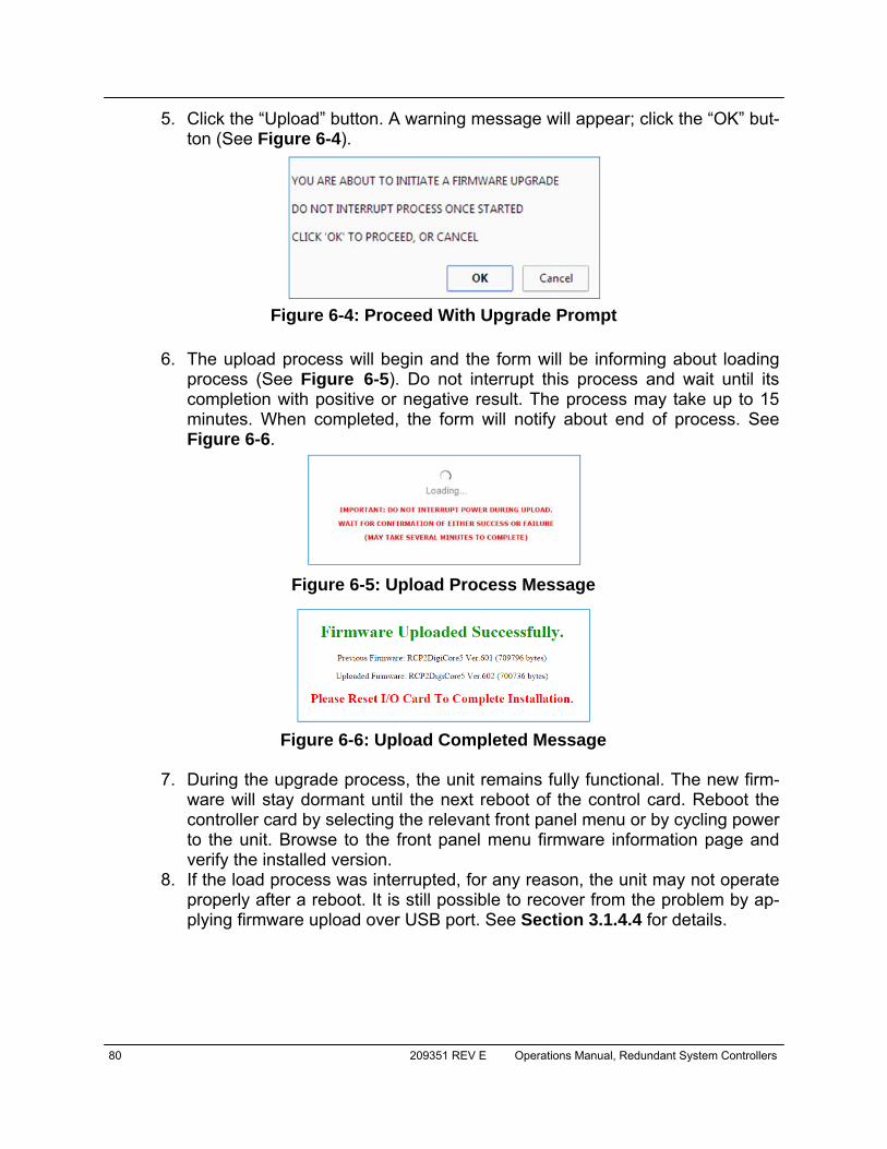
80 209351 REV E Operations Manual, Redundant System Controllers
5. Click the “Upload” button. A warning message will appear; click the “OK” but-ton (See Figure 6-4).
6. The upload process will begin and the form will be informing about loading process (See Figure 6-5). Do not interrupt this process and wait until its completion with positive or negative result. The process may take up to 15 minutes. When completed, the form will notify about end of process. See Figure 6-6.
7. During the upgrade process, the unit remains fully functional. The new firm-ware will stay dormant until the next reboot of the control card. Reboot the controller card by selecting the relevant front panel menu or by cycling power to the unit. Browse to the front panel menu firmware information page and verify the installed version.
8. If the load process was interrupted, for any reason, the unit may not operate properly after a reboot. It is still possible to recover from the problem by ap-plying firmware upload over USB port. See Section 3.1.4.4 for details.
Figure 6-4: Proceed With Upgrade Prompt
Figure 6-5: Upload Process Message
Figure 6-6: Upload Completed Message

Operations Manual, Redundant System Controllers 209351 REV E 81
6.2.4 USB Port Upgrade Procedure
1. Contact Teledyne Paradise Datacom support to obtain the latest firmware image and field programing utility. The programming utility package includes an RFU upload utility, a script file and FTDI USB drivers. Use the USB up-grade method only if the web upgrade has failed!
2. Install FTDI VCP driver on the target PC; 3. Connect the USB mini port J1 at the back of unit to an available PC USB
port. Warning! Connecting J1 to a PC USB will interrupt normal operation of the unit.
4. After connecting the unit, the target PC should recognize the newly connect-ed hardware and connect to it using the previously installed VCP FTDI driv-ers. Wait until this process is complete. Check the Windows device manager Ports section and note the newly added USB Serial Port (See Figure 6-7). You will need a COM port designator in the next step.
5. Locate and run Upgrade.bat script file which was provided in firmware up-grade package. File will open command prompt window and request pro-graming serial port designator. Enter port designator located in previous step and then press “Enter”. The script file will start downloading a new image file to the unit. The resulting window is shown in Figure 6-8;
6. Unplug the USB cable from the control card. The unit should restart with the new firmware image.
Figure 6-7: Windows Device Manager > Ports
Figure 6-8: Command Window Showing Program Prompts
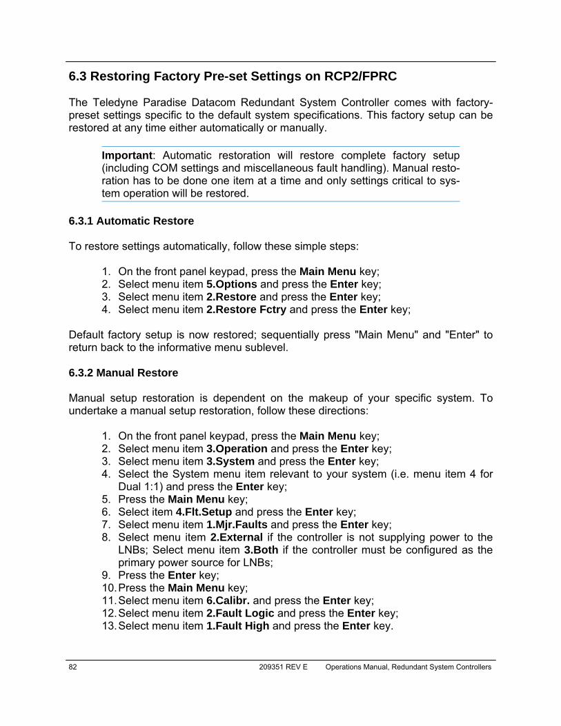
82 209351 REV E Operations Manual, Redundant System Controllers
6.3 Restoring Factory Pre-set Settings on RCP2/FPRC The Teledyne Paradise Datacom Redundant System Controller comes with factory-preset settings specific to the default system specifications. This factory setup can be restored at any time either automatically or manually.
Important: Automatic restoration will restore complete factory setup (including COM settings and miscellaneous fault handling). Manual resto-ration has to be done one item at a time and only settings critical to sys-tem operation will be restored.
6.3.1 Automatic Restore To restore settings automatically, follow these simple steps:
1. On the front panel keypad, press the Main Menu key; 2. Select menu item 5.Options and press the Enter key; 3. Select menu item 2.Restore and press the Enter key; 4. Select menu item 2.Restore Fctry and press the Enter key;
Default factory setup is now restored; sequentially press "Main Menu" and "Enter" to return back to the informative menu sublevel. 6.3.2 Manual Restore Manual setup restoration is dependent on the makeup of your specific system. To undertake a manual setup restoration, follow these directions:
1. On the front panel keypad, press the Main Menu key; 2. Select menu item 3.Operation and press the Enter key; 3. Select menu item 3.System and press the Enter key; 4. Select the System menu item relevant to your system (i.e. menu item 4 for
Dual 1:1) and press the Enter key; 5. Press the Main Menu key; 6. Select item 4.Flt.Setup and press the Enter key; 7. Select menu item 1.Mjr.Faults and press the Enter key; 8. Select menu item 2.External if the controller is not supplying power to the
LNBs; Select menu item 3.Both if the controller must be configured as the primary power source for LNBs;
9. Press the Enter key; 10. Press the Main Menu key; 11. Select menu item 6.Calibr. and press the Enter key; 12. Select menu item 2.Fault Logic and press the Enter key; 13. Select menu item 1.Fault High and press the Enter key.

Operations Manual, Redundant System Controllers 209351 REV E 83
Skip the following steps if the controller is not configured as a primary power source for the system's LNBs. Re-calibration of LNB's fault window:
1. Make sure the LNBs are reliably connected to the controller; 2. Make sure that all LNBs are normally operational prior to system calibration; 3. Make sure the controller is configured for tracking both LNA/LNB and
external faults, if not sure, repeat steps 8 to 14; 4. Press the Main Menu key; 5. Select menu item 6.Calibr. and press the Enter key; 6. Select item 1.Fault Window and press the Enter key; 7. Select item 1.8% and press the Enter key; 8. Press the Main Menu key; 9. Select menu item 6.Calibr. and press the Enter key; 10. Select item 3.Calibrate LNAs and press the Enter key.
The controller should now be configured to work in a VSAT 1:1 Redundancy system.

84 209351 REV E Operations Manual, Redundant System Controllers
6.4 Identifying and Replacing a Failed Power Supply A power supply fault is always considered a major fault, and will cause the front panel Summary Alarm and Power Supply Alarm LEDs to illuminate. To identify which power supply module is faulted, follow these steps:
1. On the front panel keypad, press the Main Menu key. 2. Select menu item 1.Sys Info and press the Enter key. 3. The resulting screen shows the status of both power supplies PS1 and PS2
on the left side of the display. The controller monitors the output voltage of each power supply module. If the output voltage level for a power supply is above 23V, the display will read Normal. If the output voltage drops below 22V, the display will read Fault.
When looking at the back panel of the RCP, PS1 is on the left and PS2 is on the right. 6.4.1 Removing a Faulted Power Supply Module To remove a faulted power supply module from the RCP chassis, perform the following steps:
1. Loosen the two captured thumbscrews securing the module to the chassis; 2. Slide the module out of the chassis; 3. Unplug the quick-disconnect power pole connectors.
6.4.2 Installing a New Power Supply Module
First, ensure that the new power supply module is the same type as the one being replaced! See Section 2.6 to review the different pow-er supply module types.
To install a new power supply module into the RCP chassis, perform the following steps:
1. Plug together the quick-connect power pole connectors; 2. Slide the module into the chassis, taking care not to pinch the power cables; 3. Tighten the two captured thumbscrews to secure the module to the chassis.
Operations Manual, Redundant System Controllers 209351 REV E 85
7.0 Overview A system, which includes a RCP2, can be managed from a remote computer over a variety of remote control interfaces (see Figure 7-1).
The parallel port on the RCP unit provides a simple form of remote control. There are 10 Form C relay contacts for remote monitoring. There are six opto-isolated inputs for remote control commands. To enable the remote parallel interface, select Remote on the front panel Local/Remote key. When in Remote mode, all front panel commands are disabled with the exception of the Local/Remote key. See Section 7.1. The serial interface supports both RS-232 and RS-485 standards. The control protocol supports two formats: the Normal serial protocol (as detailed in Section 7.2); and an ASCII based protocol suitable for HyperTerminal applications (see Section 7.5). Serial interface is equipped with overvoltage and overcurrent protection and benefits from full galvanic isolation from the chassis ground for extra protection. The Ethernet interface supports multiple communication standards which can be used exclusively or simultaneously depending on the selected setting:
• IPNet - UDP encapsulated Normal serial protocol (Section 7.6.2); • SNMP V1 with support of SNMP traps (Section 7.6.3); • HTTP web interface (Section 7.6.4);
Figure 7-1: RCP2 Remote Control Interface Stack
Remote control interface stack
SNMP
HTTP Web
10Base-T IP Interface
UDP
Alarm Contact
Protocols:1. Normal
2. Terminal
RS485
RS232
Serial Interface
Section 7: Remote Control Interface
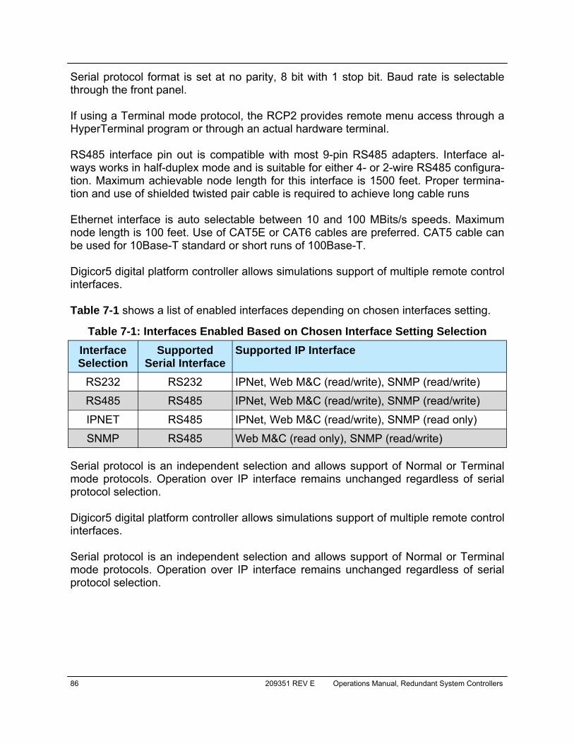
86 209351 REV E Operations Manual, Redundant System Controllers
Serial protocol format is set at no parity, 8 bit with 1 stop bit. Baud rate is selectable through the front panel. If using a Terminal mode protocol, the RCP2 provides remote menu access through a HyperTerminal program or through an actual hardware terminal. RS485 interface pin out is compatible with most 9-pin RS485 adapters. Interface al-ways works in half-duplex mode and is suitable for either 4- or 2-wire RS485 configura-tion. Maximum achievable node length for this interface is 1500 feet. Proper termina-tion and use of shielded twisted pair cable is required to achieve long cable runs Ethernet interface is auto selectable between 10 and 100 MBits/s speeds. Maximum node length is 100 feet. Use of CAT5E or CAT6 cables are preferred. CAT5 cable can be used for 10Base-T standard or short runs of 100Base-T. Digicor5 digital platform controller allows simulations support of multiple remote control interfaces. Table 7-1 shows a list of enabled interfaces depending on chosen interfaces setting.
Serial protocol is an independent selection and allows support of Normal or Terminal mode protocols. Operation over IP interface remains unchanged regardless of serial protocol selection. Digicor5 digital platform controller allows simulations support of multiple remote control interfaces. Serial protocol is an independent selection and allows support of Normal or Terminal mode protocols. Operation over IP interface remains unchanged regardless of serial protocol selection.
Interface Selection
Supported Serial Interface
Supported IP Interface
RS232 RS232 IPNet, Web M&C (read/write), SNMP (read/write)
RS485 RS485 IPNet, Web M&C (read/write), SNMP (read/write)
IPNET RS485 IPNet, Web M&C (read/write), SNMP (read only)
SNMP RS485 Web M&C (read only), SNMP (read/write)
Table 7-1: Interfaces Enabled Based on Chosen Interface Setting Selection
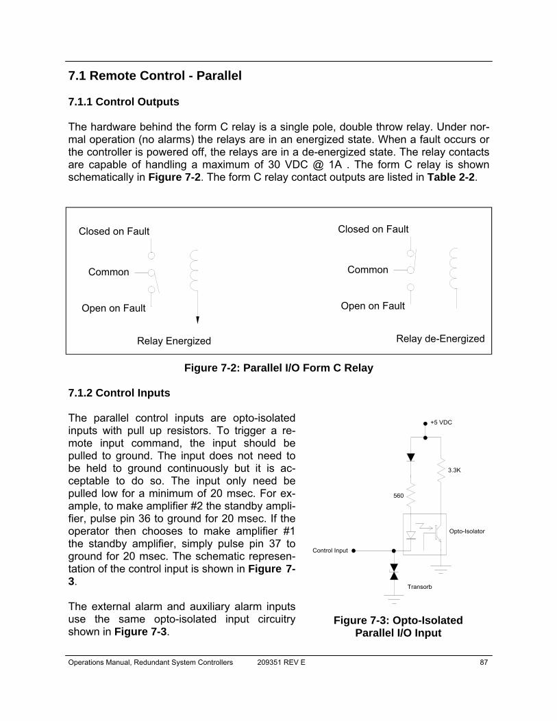
Operations Manual, Redundant System Controllers 209351 REV E 87
7.1 Remote Control - Parallel 7.1.1 Control Outputs The hardware behind the form C relay is a single pole, double throw relay. Under nor-mal operation (no alarms) the relays are in an energized state. When a fault occurs or the controller is powered off, the relays are in a de-energized state. The relay contacts are capable of handling a maximum of 30 VDC @ 1A . The form C relay is shown schematically in Figure 7-2. The form C relay contact outputs are listed in Table 2-2.
7.1.2 Control Inputs The parallel control inputs are opto-isolated inputs with pull up resistors. To trigger a re-mote input command, the input should be pulled to ground. The input does not need to be held to ground continuously but it is ac-ceptable to do so. The input only need be pulled low for a minimum of 20 msec. For ex-ample, to make amplifier #2 the standby ampli-fier, pulse pin 36 to ground for 20 msec. If the operator then chooses to make amplifier #1 the standby amplifier, simply pulse pin 37 to ground for 20 msec. The schematic represen-tation of the control input is shown in Figure 7-3. The external alarm and auxiliary alarm inputs use the same opto-isolated input circuitry shown in Figure 7-3.
Common
Relay Energized
Closed on Fault
Open on Fault
Common
Relay de-Energized
Closed on Fault
Open on Fault
Figure 7-2: Parallel I/O Form C Relay
3.3K
560
+5 VDC
Control Input
Opto-Isolator
Transorb
Figure 7-3: Opto-Isolated Parallel I/O Input

88 209351 REV E Operations Manual, Redundant System Controllers
7.2 Serial Communication This section describes the normal communication protocol between the RCP2 and a host computer over RS232/RS485 serial interface. Serial port settings on host computer must be configured for 8-bit data at no parity, with 1 stop bit. Baud rate should match selected baud rate parameter on RCP2 unit. The unit will only respond to properly formatted protocol packets. Figure 7-4 shows the basic communication packet. It consists of a Header, Data, and Trailer sub-packet.
7.2.1 Header Packet The Header packet is divided into three sub-packets which are the Frame Sync, Destination Address, and Source Address packets, as shown in Figure 7-5.
7.2.1.1 Frame Sync Word The Frame Sync word is a two byte field that marks the beginning of a packet. This val-ue is always 0xAA55. This field provides a means of designating a specific packet from others that may exist on the same network. It also provides a mechanism for a node to synchronize to a known point of transmission. 7.2.1.2 Destination Address The destination address field specifies the node for which the packet is intended. It may be an individual or broadcast address. The broadcast address is 0xFF or 0xAA (see Section 7.2.5 Multiple Device Access). This is used when a packet of information is intended for several nodes on the network. The broadcast address can be used in a single device connection when the host needs to determine the address of the amplifier. The RCP2 unit will reply with its unique address.
HEADER (4 bytes)
DATA (6-32 bytes)
Figure 7-4: Basic Communication Packet
TRAILER (1 byte)
HEADER (4 bytes)
DATA (6-32 bytes)
TRAILER (1 byte)
Frame Sync (2 bytes) 0xAA5
Destination Address (1 byte)
Source Address (1 byte)
Figure 7-5: Header Sub-Packet

Operations Manual, Redundant System Controllers 209351 REV E 89
7.2.1.3 Source Address The source address specifies the address of the node that is sending the packet. All unique addresses, except the broadcast address, are equal and can be assigned to individual units. The host computer must also have a unique network address. 7.2.2 Data Packet The data sub-packet is comprised of six to 32 bytes of information. It is further divided into seven fields as shown in Figure 7-6. The first six fields comprise the command preamble while the last field is the actual data.
7.2.2.1 Protocol ID This field provides backward compatibility with older generation equipment protocol. It should normally be set to zero. This field allows the unit to auto-detect other protocol versions, which may exist in the future. 7.2.2.2 Request ID This is an application specific field. The amplifier will echo this byte back in the response frame without change. This byte serves as a request tracking feature. 7.2.2.3 Command The RCP2 protocol is a table based protocol. It allows the user to view and modify data tables located on the controlled device. Throughout the remainder of this description, “sender” will refer to the host PC, and “receiver” will refer to the RCP2 unit. Sender and receiver are limited to two commands and two command responses. The Get Request command issued by a command sender allows monitoring of existing conditions and parameters on the receiver. The Get Request frame should not have any bytes in the Data Filed and be no longer than 11 bytes.
HEADER (4 bytes)
DATA (6-32 bytes)
TRAILER (1 byte)
DATA FIELD
Protocol ID 1 Byte
Request ID 1 Byte
Command 1 Byte
Data Tag 1 Byte
Error Status / Data Address
1 Byte
Data Length 1 Byte
Command Data Sub Structure
0 - 26 Bytes
COMMAND PREAMBLE
Figure 7-6: Data Sub-Packet

90 209351 REV E Operations Manual, Redundant System Controllers
The Response frame from the receiver will contain a Get Response designator in the Command field. If the receiver does not detect any errors in the Get Request frame, the requested data will be attached to the response frame. The length of the Get Response frame varies by the amount of attached data bytes. It may contain 11+N bytes where N is the amount of requested data bytes from a particular table, specified in the Data Length field. The Set Request command allows the sender to actively change parameters for the receiver’s internal configuration. The Set Request frame must contain a number of bytes in the Data Field as specified in the Data length field. The frame size must be 11+N bytes, where N is the length of the attached data structure. The receiver will respond with a frame where the command field will be set to a Set Response designator. The frame length is equal to the Request frame. The byte value for each command is given in Table 7-2.
7.2.2.4 Data Tag The RCP2 internal structure is organized in several tables, all of which share similar functionality and internal resources. To access the various tables, the data tag must be specified in the request frame. The data associated with certain tags is read only. Therefore only the “Get” command request would be allowed to access these data tags. The RCP2 will return an error on attempts to issue a “Set” request to a read-only table tag. Various tables may contain values formatted either in 1 or 2 bytes format. The Packet Wrapper Tag provides direct access to the RCP2 Local Port and has no table association. The data tag byte values are given in Table 7-3.
Command Name Command Byte Value
Set Request 0 Get Request 1
Set Response 2 Get Response 3
Table 7-2: Command Byte Values

Operations Manual, Redundant System Controllers 209351 REV E 91
7.2.2.5 Data Address / Error Status / Local Port Frame Length This field is a tag extension byte and specifies the first table element of the tagged da-ta. If the Data Length is more than 1 byte, then all subsequent data fields must be ac-cessed starting from the specified address. For example, if the requestor wants to ac-cess the amplifier’s unique network address, it should set data tag 0 (System settings tag) and data address 8 (see Table 7-7, System Settings Details table). If the following Data Length field is more than 1, then all subsequent Settings will be accessed after the Unique Network Address.
Important! In the Response Frame Data Address filed replaced with the Error Status information. The various error codes are given in Table 7-4.
In case of Packet Wrapper request frame (Tag 6), data address field used to specify amount of bytes returned by RCP unit in response frame from local port. Byte collecting from local port starts immediately after wrapped frame being send out. There is no time-out and response frame is not being sent back to host PC until specified amount of bytes collected from Local Port. New request sent by PC host will cancel byte collecting and all collected bytes will be discarded.
Tag Name Data Tag
Byte Value
Minimum valid
length of the Data
Field
Description
System Settings Tag 0 1 Byte
This tag allows accessing various system settings on re-mote unit. Host access status: Full Read/Write access. Settings can be modified at any time. Some of the set-tings may require hardware reset of the remote RCP unit.
System Thresholds Tag 1 2 Bytes This tag allows access to the critical unit thresholds. Host
access status: Tag have read only status.
System Conditions Tag 3 1 Byte
This tag allows access to the unit’s internal conditions flags, such as fault status or current system status. Host access status: Read only. This type of the data can not be set or modified remotely.
ADC Channels Access Tag 4 2 Bytes ADC legacy access. Don’t use for new development
Reserved 6 N/A This tag is reserved Reserved 2 N/A This tag is reserved. Reserved 5 N/A This tag is reserved for factory use only
Table 7-3: Data Tag Byte Values
Special Command Tag (v.6.00) 10 N/A This tag is reserved for factory use only
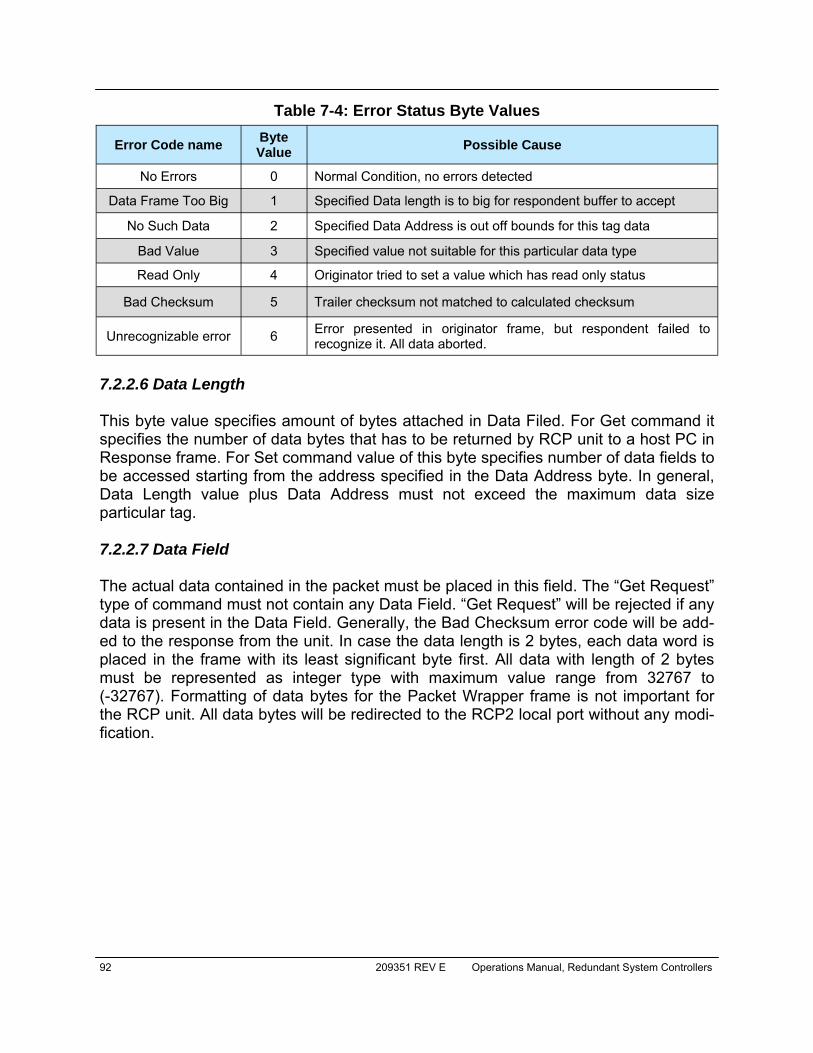
92 209351 REV E Operations Manual, Redundant System Controllers
7.2.2.6 Data Length This byte value specifies amount of bytes attached in Data Filed. For Get command it specifies the number of data bytes that has to be returned by RCP unit to a host PC in Response frame. For Set command value of this byte specifies number of data fields to be accessed starting from the address specified in the Data Address byte. In general, Data Length value plus Data Address must not exceed the maximum data size particular tag. 7.2.2.7 Data Field The actual data contained in the packet must be placed in this field. The “Get Request” type of command must not contain any Data Field. “Get Request” will be rejected if any data is present in the Data Field. Generally, the Bad Checksum error code will be add-ed to the response from the unit. In case the data length is 2 bytes, each data word is placed in the frame with its least significant byte first. All data with length of 2 bytes must be represented as integer type with maximum value range from 32767 to (-32767). Formatting of data bytes for the Packet Wrapper frame is not important for the RCP unit. All data bytes will be redirected to the RCP2 local port without any modi-fication.
Error Code name Byte Value Possible Cause
No Errors 0 Normal Condition, no errors detected
Data Frame Too Big 1 Specified Data length is to big for respondent buffer to accept
No Such Data 2 Specified Data Address is out off bounds for this tag data
Bad Value 3 Specified value not suitable for this particular data type
Read Only 4 Originator tried to set a value which has read only status
Bad Checksum 5 Trailer checksum not matched to calculated checksum
Unrecognizable error 6 Error presented in originator frame, but respondent failed to recognize it. All data aborted.
Table 7-4: Error Status Byte Values
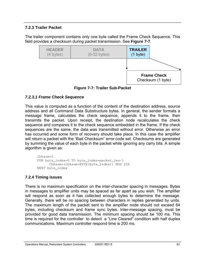
Operations Manual, Redundant System Controllers 209351 REV E 93
7.2.3 Trailer Packet The trailer component contains only one byte called the Frame Check Sequence. This field provides a checksum during packet transmission. See Figure 7-7.
7.2.3.1 Frame Check Sequence This value is computed as a function of the content of the destination address, source address and all Command Data Substructure bytes. In general, the sender formats a message frame, calculates the check sequence, appends it to the frame, then transmits the packet. Upon receipt, the destination node recalculates the check sequence and compares it to the check sequence embedded in the frame. If the check sequences are the same, the data was transmitted without error. Otherwise an error has occurred and some form of recovery should take place. In this case the amplifier will return a packet with the “Bad Checksum” error code set. Checksums are generated by summing the value of each byte in the packet while ignoring any carry bits. A simple algorithm is given as: Chksum=0 FOR byte_index=0 TO byte_index=packet_len-1 Chksum=(chksum+BYTE[byte_index]) MOD 256 NEXT byte_index
7.2.4 Timing issues There is no maximum specification on the inter-character spacing in messages. Bytes in messages to amplifier units may be spaced as far apart as you wish. The amplifier will respond as soon as it has collected enough bytes to determine the message. Generally, there will be no spacing between characters in replies generated by units. The maximum length of the packet sent to the amplifier node should not exceed 64 bytes, including checksum and frame sync bytes. Inter-message spacing, must be provided for good data transmission. The minimum spacing should be 100 ms. This time is required for the controller to detect a “Line Cleared” condition with half duplex communications. Maximum controller respond time is 200 ms.
HEADER (4 bytes)
DATA (6-32 bytes)
TRAILER (1 byte)
Frame Check Checksum (1 byte)
Figure 7-7: Trailer Sub-Packet

94 209351 REV E Operations Manual, Redundant System Controllers
7.3 Serial Communications Protocol Tables 7-5 through 7-9 detail the various values of the serial communications protocol.
Byte Tag Description 1 0xAA Frame Sync 1 2 0x55 Frame Sync 2 3 Destination Address - // - 4 Source Address -// - 5 Protocol Version Protocol Compatibility Byte, must be set 0 6 Request ID Service Byte 7 Command 0 = Set Request; 1 = Get Request
8 Data Tag 0 = System Settings; 1 = System Thresholds; 2 = Reserved; 3 = Conditions; 4 = ADC Data;
5 = Reserved; 6 = Packet Wrapper
9 Data Address Setting number, Sensor command, EEPROM address
10 Data Length Total length of the data, valid values: 1 – 10 11+N Data Actual Data
11+N+1 Checksum Destination Address + Source Address + Protocol
Version + Request ID + Command + Data Tag + Data Address + Data Length + Data
Table 7-4: Request Frame Structure
Byte Tag Description 1 0xAA Frame Sync 1 2 0x55 Frame Sync 2 3 Destination Address - // - 4 Source Address -// - 5 Protocol Version Protocol Compatibility Byte, must be set 0 6 Request ID Service Byte 7 Command 2 Set Response; 3 Get Response
8 Data Tag 0 System Settings; 1 System Thresholds; 2 Reserved; 3 Conditions; 4 ADC Data;
5 Reserved; 6 Packet Wrapper
9 Error Status 0 – No Errors, 1- Too Big, 2 No Such Data,
3 Bad Value, 4 Read Only, 5 Bad Checksum; 6 Un-recognized Error
10 Data Length Total length of the data, valid values: 1 – 10 11+N Data Actual Data
11+N+1 Checksum Destination Address + Source Address + Protocol
Version + Request ID + Command + Data Tag + Data Address + Data Length + Data
Table 7-5:. Response Frame Structure
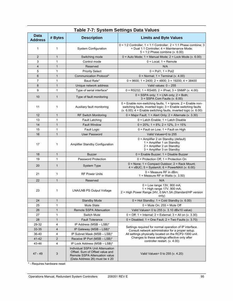
Operations Manual, Redundant System Controllers 209351 REV E 95
Table 7-7: System Settings Data Values Data
Address # Bytes Description Limits and Byte Values
1 1 System Configuration 0 = 1:2 Controller; 1 = 1:1 Controller; 2 = 1:1 Phase combine; 3
= Dual 1:1 Controller; 4 = Maintenance Mode; 5 = 1:2 Phase combine (v. 6.00)
2 1 Switching mode 0 = Auto Mode; 1 = Manual Mode; 2 = Lock Mode (v. 6.00) 3 1 Control mode 0 = Local; 1 = Remote 4 1 Reserved N/A 5 1 Priority Select 0 = Pol1; 1 = Pol2 6 1 Communication Protocol* 0 = Normal; 1 = Terminal (v. 4.00) 7 1 Baud Rate* 0 = 9600; 1 = 2400; 2 = 4800; 3 = 19200; 4 = 38400 8 1 Unique network address Valid values: 0 – 255 9 1 Type of serial interface* 0 = RS232; 1 = RS485; 2 = IPnet; 3 = SNMP (v. 4.00)
10 1 Type of fault monitoring 0 = SSPA only; 1 = LNA only; 2 = Both; 3 = SSPA Com Faults (v. 6.00)
11 1 Auxiliary fault monitoring 0 = Enable non-switching faults; 1 = Ignore; 2 = Enable non-switching faults, inverted logic; 3 = Enable switching faults
(v. 6.00); 4 = Enable switching faults, inverted logic (v. 6.00) 12 1 RF Switch Monitoring 0 = Major Fault; 1 = Alert Only; 2 = Alternate (v. 3.30) 13 1 Fault Latching 0 = Latch Enable; 1 = Latch Disable 14 1 Fault Window 0 = 20%; 1 = 8%; 2 = 12%, 3 = 15% 15 1 Fault Logic 0 = Fault on Low; 1 = Fault on High 16 1 User Password Valid Values=0 to 255
17 1 Amplifier Standby Configuration 0 = Amplifier 2 on Standby (default)
1 = Amplifier 1 on Standby 2 = Amplifier 2 on Standby 3 = Amplifier 3 on Standby
18 1 Buzzer 0 = Enable Buzzer; 1 = Disable Buzzer 19 1 Password Protection 0 = Protection Off; 1 = Protection On 20 1 System Type 0 = None; 1 = Compact Outdoor; 2 = Rack Mount;
4 = vBUC; 5 = SystemX; 6 = PowerMAX (v. 6.00) 21 1 RF Power Units 0 = Measure RF in dBm;
1 = Measure RF in Watts (v. 3.50) 22 1 Reserved N/A
23 1 LNA/LNB PS Output Voltage 0 = Low range 13V, 900 mA; 1 = High range 17V, 900 mA;
2 = High Power Range 24V, 0.9A/1.5A (Standard/HP version only)
24 1 Standby Mode 0 = Hot Standby; 1 = Cold Standby (v. 6.00) 25 1 Mute State 0 = Mute On; 255 = Mute Off 26 1 Remote SSPA Attenuation Valid Values= 0 to 255 (v. 3.10 dBx10 value) 27 1 Switch Mute 0 = Off; 1 = Internal; 2 = External; 3 = All on (v. 3.30) 28 1 Fault Tolerance 0 = Disabled; 1 = One Fault; 2 = Two Faults (v. 3.70)
29-32 4 IP Address (MSB – LSB)* Settings required for normal operation of IP interface.
Consult network administrator for a proper setup. All settings physically located on the RCP2-1000 unit.
Changes to these settings effective only after controller restart. (v. 4.00)
33-35 4 IP Gateway (MSB – LSB)* 36-40 4 IP Subnet Mask (MSB – LSB)* 41-42 2 Receive IP Port (MSB – LSB)* 43-46 4 IP Lock Address (MSB – LSB)*
47 - 49 3
Individual SSPA Unit Attenuation Offset. Sum of Offset value and Remote SSPA Attenuation value (Data Address 26) must be ≤ 20
Valid Values= 0 to 255 (v. 4.20)
* - Requires hardware reset

96 209351 REV E Operations Manual, Redundant System Controllers
Data Address # Bytes Description Limits and valid values
1 1 Unit 1 Fault state 0 = No Fault; 1 = Fault; 2 = Ignored 2 1 Unit 2 Fault state 0 = No Fault; 1 = Fault; 2 = Ignored 3 1 Unit 3 Fault state 0 = No Fault; 1 = Fault; 2 = Ignored 4 1 Summary Fault 0 = No Fault; 1 = Fault 5 1 Power Supply 1 Fault State 0 = No Fault; 1 = Fault 6 1 Power Supply 2 Fault State 0 = No Fault; 1 = Fault 7 1 Auxiliary input Fault State 0 = No Fault; 1 = Fault; 2 = Ignored
8 1 External Port State Bit 0-2 = SSPA Input lines Bit 3-8 = Auxiliary Input lines
9 1 LNA Faults Bit 0 = 1, Faults enabled; Bit 0 = 0, Faults disabled;
Bit 1 = 1, Unit 1 Fault; Bit 2 = 1, Unit 2 Fault; Bit 3 = 1, Unit 3 Fault; Bits 1-3 = 0, No Fault
10 1 SSPA Faults Bit 0 = 1, Faults enabled; Bit 0 = 0, Faults disabled;
Bit 1 = 1, Unit 1 Fault; Bit 2 = 1, Unit 2 Fault; Bit 3 = 1, Unit 3 Fault; Bits 1-3 = 0, No Fault
11 1 RF Switch 1 position 1= Switch Fault; 2 = Switch Ignore; 3 = Position 1; 4 = Position 2
12 1 RF Switch 2 position 1= Switch Fault; 2 = Switch Ignore; 3 = Position 1; 4 = Position 2
13-14 2 Forward RF Power
(available only with systems equipped with Forward RF power meter)
If Setting RF Power Units = 0, Value x 10dBm; If Setting RF Power Units = 1, Value x 10 W; (See Table 7-6, Data Address 21 for details)
(-100 for N/A (0xFF9C); Low Byte First (v. 3.10)
15-16 2 Ambient Temperature in (oC)
(available only with systems equipped with Forward RF power meter)
Value x 1 °C N/A=0xFF9C (if parameter is not available at present time);
Low Byte First (v. 3.10)
17-18 2 Core Temperature of SSPA Unit 1
(available only with systems with remote SSPA control enabled)
Value x 1 °C N/A=0xFF9C (if parameter is not available at present time);
Low Byte First (v. 3.10)
19-20 2 Core Temperature of SSPA Unit 2
(available only with systems with remote SSPA control enabled)
Value x 1 °C N/A=0xFF9C (if parameter is not available at present time);
Low Byte First (v. 3.10)
21-22 2 Core Temperature of SSPA Unit 3
(available only with systems with remote SSPA control enabled)
Value x 1 °C N/A=0xFF9C (if parameter is not available at present time);
Low Byte First (v. 3.10)
23-24 2 Reflected RF Power
(available only with systems equipped with Reflected RF power meter)
If Setting RF Power Units = 0, Value x 10dBm; If Setting RF Power Units = 1, Value x 10 W; (See Table 7-6, Data Address 21 for details)
(-100 for N/A (0xFF9C); Low Byte First (version 3.30) 25-26 2 DC Current (Unit 1 in Amps) Value x 10 Amp; N/A=0XFF9C; Low Byte First (v. 3.60) 27-28 2 DC Current (Unit 2 in Amps) Value x 10 Amp; N/A=0XFF9C; Low Byte First (v. 3.60) 29-30 2 DC Current (Unit 3 in Amps) Value x 10 Amp; N/A=0XFF9C; Low Byte First (v. 3.60) 31-32 2 Forward RF Power (Unit 1 in dBm) Value x 10 dBm; N/A=0XFF9C; Low Byte First (v. 3.60) 33-34 2 Forward RF Power (Unit 2 in dBm) Value x 10 dBm; N/A=0XFF9C; Low Byte First (v. 3.60) 35-36 2 Forward RF Power (Unit 3 in dBm) Value x 10 dBm; N/A=0XFF9C; Low Byte First (v. 3.60)
Table 7-8: System Condition Data Values

Operations Manual, Redundant System Controllers 209351 REV E 97
Data Address # Bytes Description Limits and valid values
1 2 LNA Unit 1 Calibration Data Point conversion: 0.57 mA per 1 value increment, maximum value =4095 (2.3A) (read/write)
2 2 LNA Unit 2 Calibration Data Point conversion: 0.57 mA per 1 value increment, maximum value =4095 (2.3A) (read/write)
3 2 LNA Unit 3 Calibration Data Point conversion: 0.57 mA per 1 value increment, maximum value =4095 (2.3A) (read/write)
Table 7-9: System Threshold Data Values
4 2 LNA Unit 1 DC Current Point conversion: 0.57 mA per 1 value increment, maximum value =4095 (2.3A) (v6.00) (read only)
5 2 LNA Unit 2 DC Current Point conversion: 0.57 mA per 1 value increment, maximum value =4095 (2.3A) (v6.00) (read only)
6 2 LNA Unit 3 DC Current Point conversion: 0.57 mA per 1 value increment, maximum value =4095 (2.3A) (v6.00) (read only)
7 2 LNA Unit 1 DC Voltage Point conversion: 0.1 V per 1 value increment, maximum value =1023 (v6.00) (read only)
8 2 LNA Unit 2 DC Voltage Point conversion: 0.1 V per 1 value increment, maximum value =1023 (v6.00) (read only)
9 2 LNA Unit 3 DC Voltage Point conversion: 0.1 V per 1 value increment, maximum value =1023 (v6.00) (read only)
10 2 PS1 DC Voltage Point conversion: 0.1 V per 1 value increment, maximum value =1023 (v6.00) (read only)
11 2 PS2 DC Voltage Point conversion: 0.1 V per 1 value increment, maximum value =1023 (v6.00) (read only)
12 2 RCP2 Chassis Temperature Value x 1 °C (v6.00) (read only)
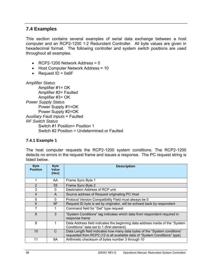
98 209351 REV E Operations Manual, Redundant System Controllers
7.4 Examples This section contains several examples of serial data exchange between a host computer and an RCP2-1200 1:2 Redundant Controller. All byte values are given in hexadecimal format. The following controller and system switch positions are used throughout all examples.
• RCP2-1200 Network Address = 0 • Host Computer Network Address = 10 • Request ID = 0x6F
Amplifier Status
Amplifier #1= OK Amplifier #2= Faulted Amplifier #3= OK
Power Supply Status Power Supply #1=OK Power Supply #2=OK Auxiliary Fault Inputs = Faulted RF Switch Status
Switch #1 Position= Position 1 Switch #2 Position = Undetermined or Faulted
7.4.1 Example 1 The host computer requests the RCP2-1200 system conditions. The RCP2-1200 detects no errors in the request frame and issues a response. The PC request string is listed below.
Byte Position
Byte Value (Hex)
Description
1 AA Frame Sync Byte 1 2 55 Frame Sync Byte 2 3 0 Destination Address of RCP unit 4 A Source address of Request originating PC Host 5 0 Protocol Version Compatibility Field must always be 0 6 6F Request ID byte is set by originator, will be echoed back by respondent 7 1 Command field for “Get” type request
8 3 “System Conditions” tag indicates which data from respondent required in response frame
9 1 Data Address field indicates the beginning data address inside of the “System Conditions” data set to 1 (first element)
10 C Data Length field indicates how many data bytes of the “System conditions” requested from RCP2 (12 is all available data of “System Conditions” type)
11 8A Arithmetic checksum of bytes number 3 through 10
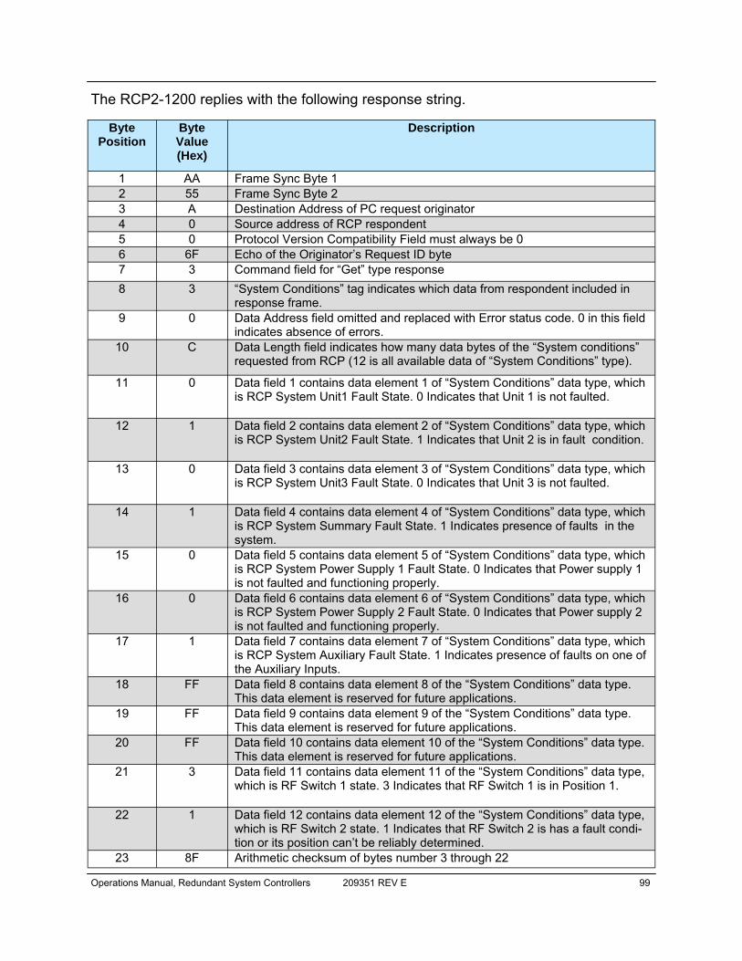
Operations Manual, Redundant System Controllers 209351 REV E 99
The RCP2-1200 replies with the following response string.
Byte Position
Byte Value (Hex)
Description
1 AA Frame Sync Byte 1 2 55 Frame Sync Byte 2 3 A Destination Address of PC request originator 4 0 Source address of RCP respondent 5 0 Protocol Version Compatibility Field must always be 0 6 6F Echo of the Originator’s Request ID byte 7 3 Command field for “Get” type response 8 3 “System Conditions” tag indicates which data from respondent included in
response frame. 9 0 Data Address field omitted and replaced with Error status code. 0 in this field
indicates absence of errors. 10 C Data Length field indicates how many data bytes of the “System conditions”
requested from RCP (12 is all available data of “System Conditions” type).
11 0 Data field 1 contains data element 1 of “System Conditions” data type, which is RCP System Unit1 Fault State. 0 Indicates that Unit 1 is not faulted.
12 1 Data field 2 contains data element 2 of “System Conditions” data type, which is RCP System Unit2 Fault State. 1 Indicates that Unit 2 is in fault condition.
13 0 Data field 3 contains data element 3 of “System Conditions” data type, which is RCP System Unit3 Fault State. 0 Indicates that Unit 3 is not faulted.
14 1 Data field 4 contains data element 4 of “System Conditions” data type, which is RCP System Summary Fault State. 1 Indicates presence of faults in the system.
15 0 Data field 5 contains data element 5 of “System Conditions” data type, which is RCP System Power Supply 1 Fault State. 0 Indicates that Power supply 1 is not faulted and functioning properly.
16 0 Data field 6 contains data element 6 of “System Conditions” data type, which is RCP System Power Supply 2 Fault State. 0 Indicates that Power supply 2 is not faulted and functioning properly.
17 1 Data field 7 contains data element 7 of “System Conditions” data type, which is RCP System Auxiliary Fault State. 1 Indicates presence of faults on one of the Auxiliary Inputs.
18 FF Data field 8 contains data element 8 of the “System Conditions” data type. This data element is reserved for future applications.
19 FF Data field 9 contains data element 9 of the “System Conditions” data type. This data element is reserved for future applications.
20 FF Data field 10 contains data element 10 of the “System Conditions” data type. This data element is reserved for future applications.
21 3 Data field 11 contains data element 11 of the “System Conditions” data type, which is RF Switch 1 state. 3 Indicates that RF Switch 1 is in Position 1.
22 1 Data field 12 contains data element 12 of the “System Conditions” data type, which is RF Switch 2 state. 1 Indicates that RF Switch 2 is has a fault condi-tion or its position can’t be reliably determined.
23 8F Arithmetic checksum of bytes number 3 through 22
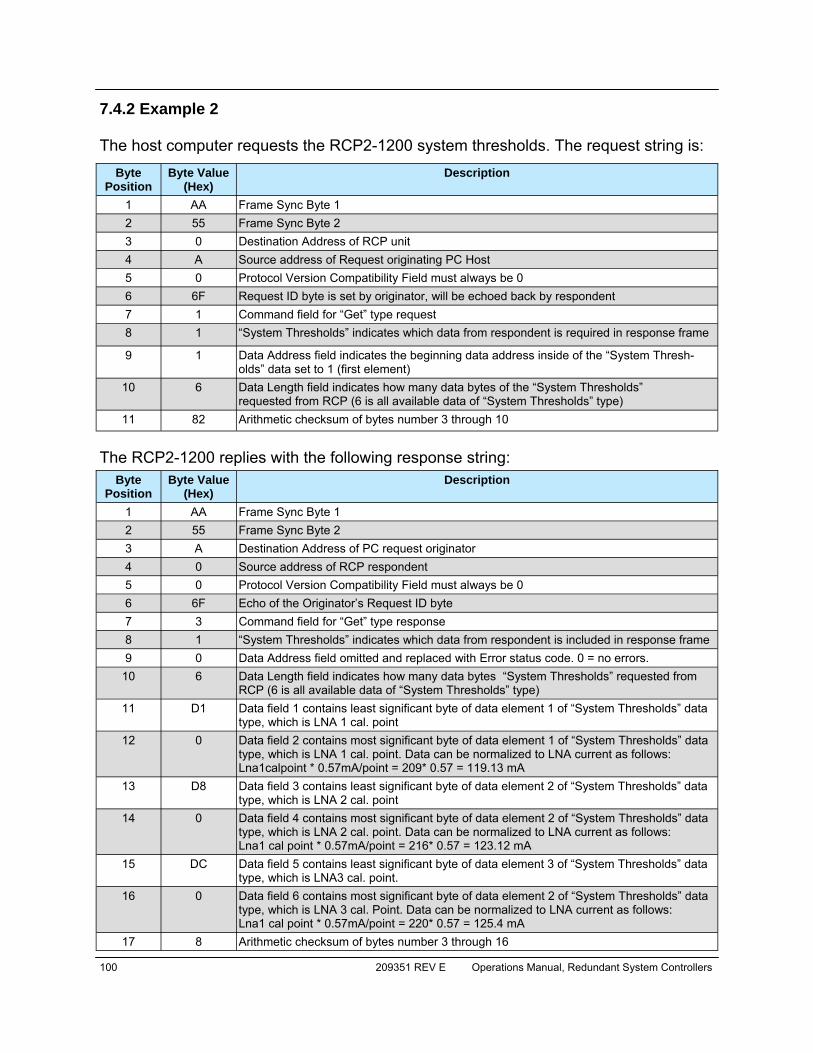
100 209351 REV E Operations Manual, Redundant System Controllers
7.4.2 Example 2 The host computer requests the RCP2-1200 system thresholds. The request string is:
The RCP2-1200 replies with the following response string:
Byte Position
Byte Value (Hex)
Description
1 AA Frame Sync Byte 1 2 55 Frame Sync Byte 2 3 0 Destination Address of RCP unit 4 A Source address of Request originating PC Host 5 0 Protocol Version Compatibility Field must always be 0 6 6F Request ID byte is set by originator, will be echoed back by respondent 7 1 Command field for “Get” type request 8 1 “System Thresholds” indicates which data from respondent is required in response frame
9 1 Data Address field indicates the beginning data address inside of the “System Thresh-olds” data set to 1 (first element)
10 6 Data Length field indicates how many data bytes of the “System Thresholds” requested from RCP (6 is all available data of “System Thresholds” type)
11 82 Arithmetic checksum of bytes number 3 through 10
Byte Position
Byte Value (Hex)
Description
1 AA Frame Sync Byte 1 2 55 Frame Sync Byte 2 3 A Destination Address of PC request originator 4 0 Source address of RCP respondent 5 0 Protocol Version Compatibility Field must always be 0 6 6F Echo of the Originator’s Request ID byte 7 3 Command field for “Get” type response 8 1 “System Thresholds” indicates which data from respondent is included in response frame 9 0 Data Address field omitted and replaced with Error status code. 0 = no errors.
10 6 Data Length field indicates how many data bytes “System Thresholds” requested from RCP (6 is all available data of “System Thresholds” type)
11 D1 Data field 1 contains least significant byte of data element 1 of “System Thresholds” data type, which is LNA 1 cal. point
12 0 Data field 2 contains most significant byte of data element 1 of “System Thresholds” data type, which is LNA 1 cal. point. Data can be normalized to LNA current as follows: Lna1calpoint * 0.57mA/point = 209* 0.57 = 119.13 mA
13 D8 Data field 3 contains least significant byte of data element 2 of “System Thresholds” data type, which is LNA 2 cal. point
14 0 Data field 4 contains most significant byte of data element 2 of “System Thresholds” data type, which is LNA 2 cal. point. Data can be normalized to LNA current as follows: Lna1 cal point * 0.57mA/point = 216* 0.57 = 123.12 mA
15 DC Data field 5 contains least significant byte of data element 3 of “System Thresholds” data type, which is LNA3 cal. point.
16 0 Data field 6 contains most significant byte of data element 2 of “System Thresholds” data type, which is LNA 3 cal. Point. Data can be normalized to LNA current as follows: Lna1 cal point * 0.57mA/point = 220* 0.57 = 125.4 mA
17 8 Arithmetic checksum of bytes number 3 through 16
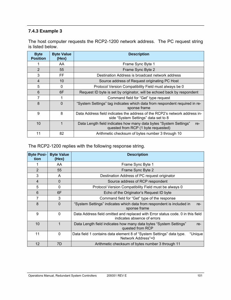
Operations Manual, Redundant System Controllers 209351 REV E 101
7.4.3 Example 3 The host computer requests the RCP2-1200 network address. The PC request string is listed below.
The RCP2-1200 replies with the following response string.
Byte Position
Byte Value (Hex)
Description
1 AA Frame Sync Byte 1 2 55 Frame Sync Byte 2 3 FF Destination Address is broadcast network address 4 10 Source address of Request originating PC Host 5 0 Protocol Version Compatibility Field must always be 0 6 6F Request ID byte is set by originator, will be echoed back by respondent 7 1 Command field for “Get” type request 8 0 “System Settings” tag indicates which data from respondent required in re-
sponse frame 9 8 Data Address field indicates the address of the RCP2’s network address in-
side “System Settings” data set to 8 10 1 Data Length field indicates how many data bytes “System Settings” re-
quested from RCP (1 byte requested) 11 82 Arithmetic checksum of bytes number 3 through 10
Byte Posi-tion
Byte Value (Hex)
Description
1 AA Frame Sync Byte 1 2 55 Frame Sync Byte 2 3 A Destination Address of PC request originator 4 0 Source address of RCP respondent 5 0 Protocol Version Compatibility Field must be always 0 6 6F Echo of the Originator’s Request ID byte 7 3 Command field for “Get” type of the response 8 0 “System Settings” indicates which data from respondent is included in re-
sponse frame 9 0 Data Address field omitted and replaced with Error status code. 0 in this field
indicates absence of errors 10 1 Data Length field indicates how many data bytes “System Settings” re-
quested from RCP 11 0 Data field 1 contains data element 8 of “System Settings” data type. “Unique
Network Address”=0 12 7D Arithmetic checksum of bytes number 3 through 11
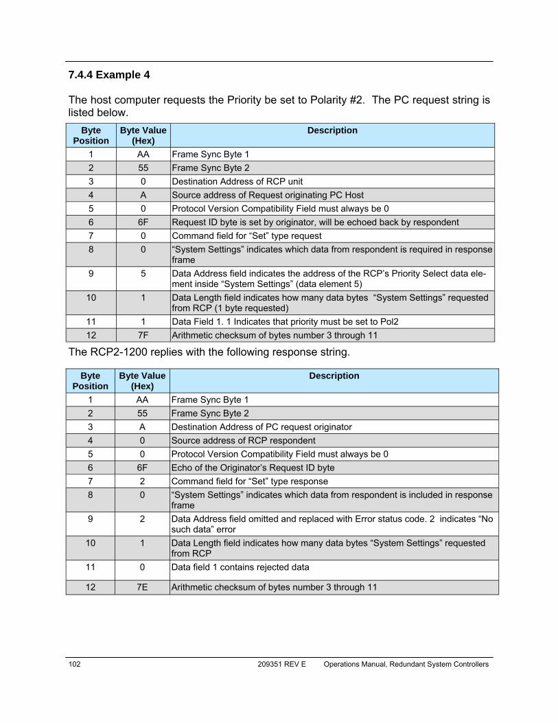
102 209351 REV E Operations Manual, Redundant System Controllers
7.4.4 Example 4 The host computer requests the Priority be set to Polarity #2. The PC request string is listed below.
The RCP2-1200 replies with the following response string.
Byte Position
Byte Value (Hex)
Description
1 AA Frame Sync Byte 1 2 55 Frame Sync Byte 2 3 0 Destination Address of RCP unit 4 A Source address of Request originating PC Host 5 0 Protocol Version Compatibility Field must always be 0 6 6F Request ID byte is set by originator, will be echoed back by respondent 7 0 Command field for “Set” type request 8 0 “System Settings” indicates which data from respondent is required in response
frame 9 5 Data Address field indicates the address of the RCP’s Priority Select data ele-
ment inside “System Settings” (data element 5) 10 1 Data Length field indicates how many data bytes “System Settings” requested
from RCP (1 byte requested) 11 1 Data Field 1. 1 Indicates that priority must be set to Pol2 12 7F Arithmetic checksum of bytes number 3 through 11
Byte Position
Byte Value (Hex)
Description
1 AA Frame Sync Byte 1 2 55 Frame Sync Byte 2 3 A Destination Address of PC request originator 4 0 Source address of RCP respondent 5 0 Protocol Version Compatibility Field must always be 0 6 6F Echo of the Originator’s Request ID byte 7 2 Command field for “Set” type response 8 0 “System Settings” indicates which data from respondent is included in response
frame 9 2 Data Address field omitted and replaced with Error status code. 2 indicates “No
such data” error 10 1 Data Length field indicates how many data bytes “System Settings” requested
from RCP 11 0 Data field 1 contains rejected data
12 7E Arithmetic checksum of bytes number 3 through 11
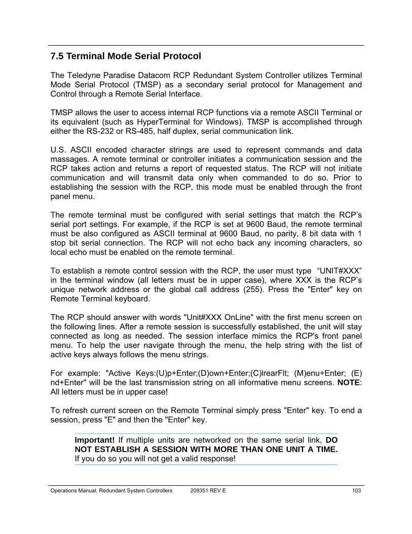
Operations Manual, Redundant System Controllers 209351 REV E 103
7.5 Terminal Mode Serial Protocol The Teledyne Paradise Datacom RCP Redundant System Controller utilizes Terminal Mode Serial Protocol (TMSP) as a secondary serial protocol for Management and Control through a Remote Serial Interface. TMSP allows the user to access internal RCP functions via a remote ASCII Terminal or its equivalent (such as HyperTerminal for Windows). TMSP is accomplished through either the RS-232 or RS-485, half duplex, serial communication link. U.S. ASCII encoded character strings are used to represent commands and data massages. A remote terminal or controller initiates a communication session and the RCP takes action and returns a report of requested status. The RCP will not initiate communication and will transmit data only when commanded to do so. Prior to establishing the session with the RCP, this mode must be enabled through the front panel menu. The remote terminal must be configured with serial settings that match the RCP’s serial port settings. For example, if the RCP is set at 9600 Baud, the remote terminal must be also configured as ASCII terminal at 9600 Baud, no parity, 8 bit data with 1 stop bit serial connection. The RCP will not echo back any incoming characters, so local echo must be enabled on the remote terminal. To establish a remote control session with the RCP, the user must type “UNIT#XXX” in the terminal window (all letters must be in upper case), where XXX is the RCP’s unique network address or the global call address (255). Press the "Enter" key on Remote Terminal keyboard. The RCP should answer with words "Unit#XXX OnLine" with the first menu screen on the following lines. After a remote session is successfully established, the unit will stay connected as long as needed. The session interface mimics the RCP's front panel menu. To help the user navigate through the menu, the help string with the list of active keys always follows the menu strings. For example: "Active Keys:(U)p+Enter;(D)own+Enter;(C)lrearFlt; (M)enu+Enter; (E)nd+Enter" will be the last transmission string on all informative menu screens. NOTE: All letters must be in upper case! To refresh current screen on the Remote Terminal simply press "Enter" key. To end a session, press "E" and then the "Enter" key.
Important! If multiple units are networked on the same serial link, DO NOT ESTABLISH A SESSION WITH MORE THAN ONE UNIT A TIME. If you do so you will not get a valid response!
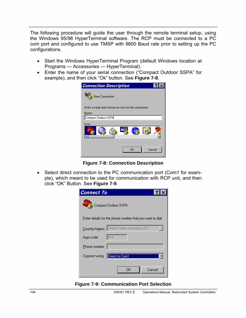
104 209351 REV E Operations Manual, Redundant System Controllers
The following procedure will guide the user through the remote terminal setup, using the Windows 95/98 HyperTerminal software. The RCP must be connected to a PC com port and configured to use TMSP with 9600 Baud rate prior to setting up the PC configurations.
• Start the Windows HyperTerminal Program (default Windows location at
Programs — Accessories — HyperTerminal). • Enter the name of your serial connection (“Compact Outdoor SSPA” for
example), and then click “Ok” button. See Figure 7-8.
• Select direct connection to the PC communication port (Com1 for exam-ple), which meant to be used for communication with RCP unit, and then click “OK” Button. See Figure 7-9.
Figure 7-8: Connection Description
Figure 7-9: Communication Port Selection
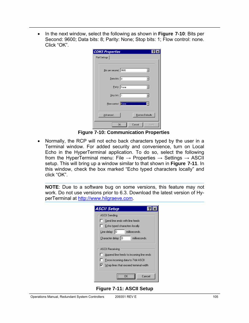
Operations Manual, Redundant System Controllers 209351 REV E 105
• In the next window, select the following as shown in Figure 7-10: Bits per Second: 9600; Data bits: 8; Parity: None; Stop bits: 1; Flow control: none. Click “OK”.
• Normally, the RCP will not echo back characters typed by the user in a Terminal window. For added security and convenience, turn on Local Echo in the HyperTerminal application. To do so, select the following from the HyperTerminal menu: File → Properties → Settings → ASCII setup. This will bring up a window similar to that shown in Figure 7-11. In this window, check the box marked “Echo typed characters locally” and click “OK”.
NOTE: Due to a software bug on some versions, this feature may not work. Do not use versions prior to 6.3. Download the latest version of Hy-perTerminal at http://www.hilgraeve.com.
Figure 7-10: Communication Properties
Figure 7-11: ASCII Setup
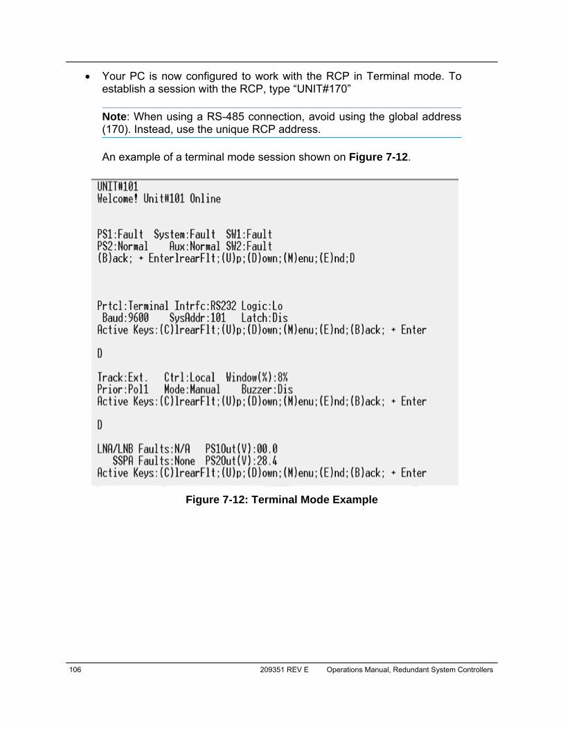
106 209351 REV E Operations Manual, Redundant System Controllers
• Your PC is now configured to work with the RCP in Terminal mode. To establish a session with the RCP, type “UNIT#170” Note: When using a RS-485 connection, avoid using the global address (170). Instead, use the unique RCP address. An example of a terminal mode session shown on Figure 7-12.
Figure 7-12: Terminal Mode Example

Operations Manual, Redundant System Controllers 209351 REV E 107
7.6 Ethernet Interface 7.6.1 Overview The RCP2 Ethernet port (J9) supports several IP network protocols to provide a full featured remote M&C interface over an Ethernet LAN.
• IPNet protocol — redirection of standard Paradise Datacom LLC serial protocol over UDP transport layer protocol. This protocol is fully support-ed in Paradise Datacom LLC’s Universal M&C software.
• SNMPv1 protocol — protocol intended for integration into large corporate NMS architectures.
• HTTP Web interface — designed to allow platform independent remote control function for a single RCP2 unit
In order to utilize either of the protocols listed above, the relevant interface option has to be turned on. Refer to Section 7.5.2 (Setting IPNet interface), Section 7.5.3 (Configure unit to work with SNMP protocol) and Section 7.5.4 (Web interface). Of course, standard IP level functions such as ICMP Ping and ARP are supported as well. There is currently no support for dynamic IP parameters settings (DHCP). 7.6.2 IPNet Interface 7.6.2.1 General Concept Satcom system integrators are recognizing the benefits of an Ethernet IP interface. These benefits include:
• Unsurpassed system integration capabilities; • Widely available and inexpensive set of support equipment (network ca-
ble; network hubs); • Ability to control equipment over Internet; • Ease of use
Implementation of the raw Ethernet interface is not practical due to the limitations it places on M&C capabilities by the range of a particular LAN. It is more practical to use an Ethernet interface in conjunction with the standard OSI (Open System Interconnect) model to carry a stack of other protocols. In an OSI layered stack, an Ethernet inter-face can be represented as a Data Link layer. All upper layers are resolved through a set of IP protocols. In order to keep data bandwidth as low as possible (which is im-portant when M&C functions are provided through a low-bandwidth service channel) the IP/UDP protocol set is used as the Network/Transport layer protocol on Teledyne Paradise Datacom SSPAs.
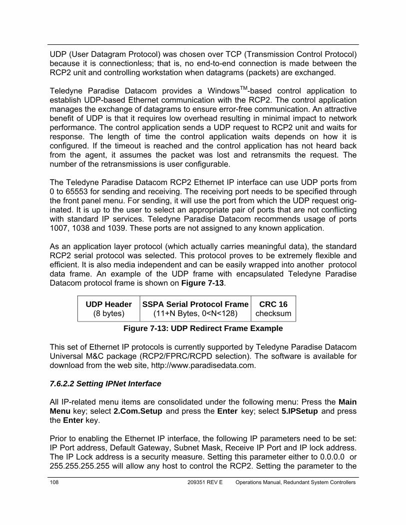
108 209351 REV E Operations Manual, Redundant System Controllers
UDP (User Datagram Protocol) was chosen over TCP (Transmission Control Protocol) because it is connectionless; that is, no end-to-end connection is made between the RCP2 unit and controlling workstation when datagrams (packets) are exchanged. Teledyne Paradise Datacom provides a WindowsTM-based control application to establish UDP-based Ethernet communication with the RCP2. The control application manages the exchange of datagrams to ensure error-free communication. An attractive benefit of UDP is that it requires low overhead resulting in minimal impact to network performance. The control application sends a UDP request to RCP2 unit and waits for response. The length of time the control application waits depends on how it is configured. If the timeout is reached and the control application has not heard back from the agent, it assumes the packet was lost and retransmits the request. The number of the retransmissions is user configurable. The Teledyne Paradise Datacom RCP2 Ethernet IP interface can use UDP ports from 0 to 65553 for sending and receiving. The receiving port needs to be specified through the front panel menu. For sending, it will use the port from which the UDP request orig-inated. It is up to the user to select an appropriate pair of ports that are not conflicting with standard IP services. Teledyne Paradise Datacom recommends usage of ports 1007, 1038 and 1039. These ports are not assigned to any known application. As an application layer protocol (which actually carries meaningful data), the standard RCP2 serial protocol was selected. This protocol proves to be extremely flexible and efficient. It is also media independent and can be easily wrapped into another protocol data frame. An example of the UDP frame with encapsulated Teledyne Paradise Datacom protocol frame is shown on Figure 7-13.
This set of Ethernet IP protocols is currently supported by Teledyne Paradise Datacom Universal M&C package (RCP2/FPRC/RCPD selection). The software is available for download from the web site, http://www.paradisedata.com. 7.6.2.2 Setting IPNet Interface All IP-related menu items are consolidated under the following menu: Press the Main Menu key; select 2.Com.Setup and press the Enter key; select 5.IPSetup and press the Enter key. Prior to enabling the Ethernet IP interface, the following IP parameters need to be set: IP Port address, Default Gateway, Subnet Mask, Receive IP Port and IP lock address. The IP Lock address is a security measure. Setting this parameter either to 0.0.0.0 or 255.255.255.255 will allow any host to control the RCP2. Setting the parameter to the
UDP Header (8 bytes)
SSPA Serial Protocol Frame (11+N Bytes, 0<N<128)
Figure 7-13: UDP Redirect Frame Example
CRC 16 checksum
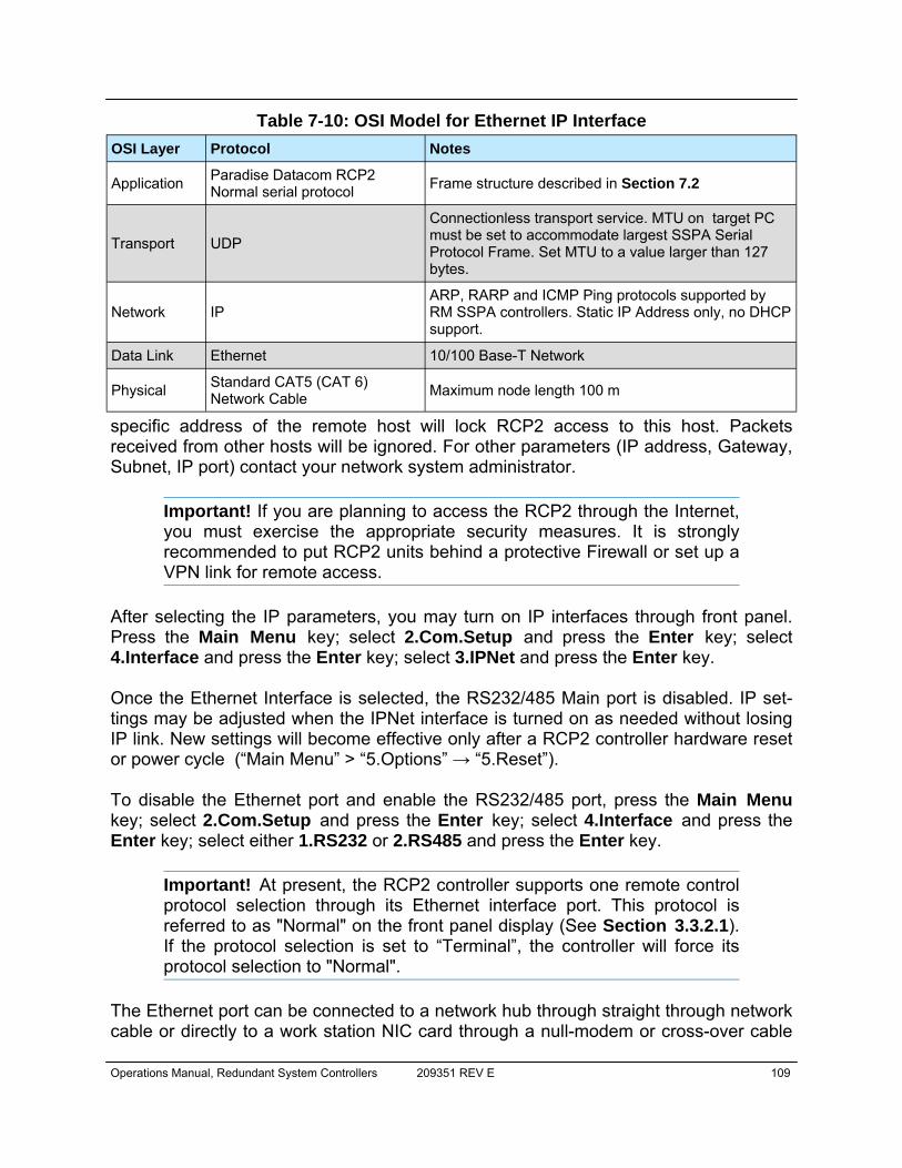
Operations Manual, Redundant System Controllers 209351 REV E 109
specific address of the remote host will lock RCP2 access to this host. Packets received from other hosts will be ignored. For other parameters (IP address, Gateway, Subnet, IP port) contact your network system administrator.
Important! If you are planning to access the RCP2 through the Internet, you must exercise the appropriate security measures. It is strongly recommended to put RCP2 units behind a protective Firewall or set up a VPN link for remote access.
After selecting the IP parameters, you may turn on IP interfaces through front panel. Press the Main Menu key; select 2.Com.Setup and press the Enter key; select 4.Interface and press the Enter key; select 3.IPNet and press the Enter key. Once the Ethernet Interface is selected, the RS232/485 Main port is disabled. IP set-tings may be adjusted when the IPNet interface is turned on as needed without losing IP link. New settings will become effective only after a RCP2 controller hardware reset or power cycle (“Main Menu” > “5.Options” → “5.Reset”). To disable the Ethernet port and enable the RS232/485 port, press the Main Menu key; select 2.Com.Setup and press the Enter key; select 4.Interface and press the Enter key; select either 1.RS232 or 2.RS485 and press the Enter key.
Important! At present, the RCP2 controller supports one remote control protocol selection through its Ethernet interface port. This protocol is referred to as "Normal" on the front panel display (See Section 3.3.2.1). If the protocol selection is set to “Terminal”, the controller will force its protocol selection to "Normal".
The Ethernet port can be connected to a network hub through straight through network cable or directly to a work station NIC card through a null-modem or cross-over cable
OSI Layer Protocol Notes
Application Paradise Datacom RCP2 Normal serial protocol Frame structure described in Section 7.2
Transport UDP
Connectionless transport service. MTU on target PC must be set to accommodate largest SSPA Serial Protocol Frame. Set MTU to a value larger than 127 bytes.
Network IP ARP, RARP and ICMP Ping protocols supported by RM SSPA controllers. Static IP Address only, no DHCP support.
Data Link Ethernet 10/100 Base-T Network
Physical Standard CAT5 (CAT 6) Network Cable Maximum node length 100 m
Table 7-10: OSI Model for Ethernet IP Interface
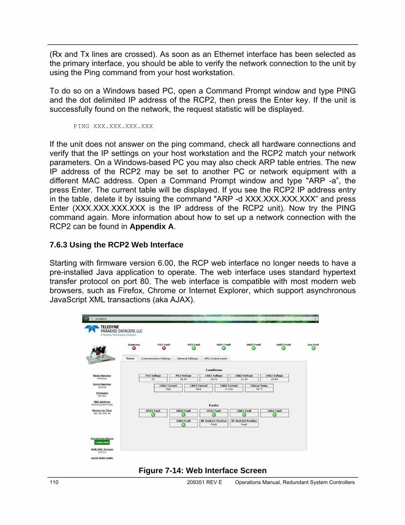
110 209351 REV E Operations Manual, Redundant System Controllers
(Rx and Tx lines are crossed). As soon as an Ethernet interface has been selected as the primary interface, you should be able to verify the network connection to the unit by using the Ping command from your host workstation. To do so on a Windows based PC, open a Command Prompt window and type PING and the dot delimited IP address of the RCP2, then press the Enter key. If the unit is successfully found on the network, the request statistic will be displayed. PING XXX.XXX.XXX.XXX
If the unit does not answer on the ping command, check all hardware connections and verify that the IP settings on your host workstation and the RCP2 match your network parameters. On a Windows-based PC you may also check ARP table entries. The new IP address of the RCP2 may be set to another PC or network equipment with a different MAC address. Open a Command Prompt window and type "ARP -a”, the press Enter. The current table will be displayed. If you see the RCP2 IP address entry in the table, delete it by issuing the command "ARP -d XXX.XXX.XXX.XXX” and press Enter (XXX.XXX.XXX.XXX is the IP address of the RCP2 unit). Now try the PING command again. More information about how to set up a network connection with the RCP2 can be found in Appendix A. 7.6.3 Using the RCP2 Web Interface Starting with firmware version 6.00, the RCP web interface no longer needs to have a pre-installed Java application to operate. The web interface uses standard hypertext transfer protocol on port 80. The web interface is compatible with most modern web browsers, such as Firefox, Chrome or Internet Explorer, which support asynchronous JavaScript XML transactions (aka AJAX).
Figure 7-14: Web Interface Screen
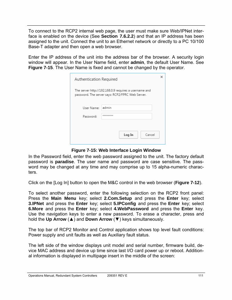
Operations Manual, Redundant System Controllers 209351 REV E 111
To connect to the RCP2 internal web page, the user must make sure Web/IPNet inter-face is enabled on the device (See Section 7.6.2.2) and that an IP address has been assigned to the unit. Connect the unit to an Ethernet network or directly to a PC 10/100 Base-T adapter and then open a web browser. Enter the IP address of the unit into the address bar of the browser. A security login window will appear. In the User Name field, enter admin, the default User Name. See Figure 7-15. The User Name is fixed and cannot be changed by the operator.
In the Password field, enter the web password assigned to the unit. The factory default password is paradise. The user name and password are case sensitive. The pass-word may be changed at any time and may comprise up to 15 alpha-numeric charac-ters. Click on the [Log In] button to open the M&C control in the web browser (Figure 7-12). To select another password, enter the following selection on the RCP2 front panel: Press the Main Menu key; select 2.Com.Setup and press the Enter key; select 3.IPNet and press the Enter key; select 5.IPConfig and press the Enter key; select 6.More and press the Enter key; select 4.WebPassword and press the Enter key. Use the navigation keys to enter a new password. To erase a character, press and hold the Up Arrow (▲) and Down Arrow (▼) keys simultaneously. The top bar of RCP2 Monitor and Control application shows top level fault conditions: Power supply and unit faults as well as Auxiliary fault status. The left side of the window displays unit model and serial number, firmware build, de-vice MAC address and device up time since last I/O card power up or reboot. Addition-al information is displayed in multipage insert in the middle of the screen:
Figure 7-15: Web Interface Login Window
112 209351 REV E Operations Manual, Redundant System Controllers
• Status: A view of all faults and operational parameters. • Communication Settings: This tab provides access to all communica-
tion related settings. From here, the user can change the IP settings, In-terface, Protocol, Baud Rate, Password and SNMP settings.
• General Settings: Read/Write listing of most adjustable RCP parame-ters. All options are selectable. To set a parameter, select the new value and click the “Confirm” button with the mouse pointer.
• HPA Control panel: All information and controls related to remotely con-trol HPA system (if available) Note: The web server has limited hardware resources to support multiple simultaneously connected users. In the case that multiple users are con-nected to the same amplifier, service quality cannot be assured.

Operations Manual, Redundant System Controllers 209351 REV E 113
7.6.4 SNMP Interface 7.6.4.1 Introduction SNMP-based management was initially targeted for TCP/IP routers and hosts. However, the SNMP-based management approach is inherently generic so that it can be used to manage many types of systems. This approach has become increasingly popular for remote management and control solutions for various SSPA systems. Teledyne Paradise Datacom devices with Ethernet interface support the most popular SNMPv1 format (SMIv1, RFC1155), SNMP Get, SNMP GetNext and SNMP Set commands. SNMP Traps are currently unsupported. In order to utilize SNMP protocol, the user has to enable this feature through the front panel or by remote serial protocol. SNMP uses the UDP fixed port 161 for sending and receiving requests. The definition of managed objects described in MIB. The MIB file is available for down-load from the Software Downloads section of the Teledyne Paradise Datacom web site, http://www.paradisedata.com. As with the serial protocol, the RCP2 MIB allows access to a remote SSPA (default state) as well as to the RCP unit itself. To switch between those devices’ MIBs, the proper Device Type has to be selected (OID -1.3.6.1.4.1.20712.1.4). The Teledyne Paradise Datacom MIB is a table-based MIB, and is the same for all de-vices. The MIB table is designed to follow the same pattern as the tables for serial pro-tocol. For additional information about OID values, refer to Table 7-11 through Table 7-13. The text values in the tables help automatic value parsing within NMS or make the values readable through an MIB browser. All text value OIDs follow the same pat-tern: 1. For settings or parameters with discreet values: SettingName’ValueName1=xxx, ….,ValueNamex=xxx Example: ControlMode’Local=0,Remote=1 2. For settings or parameters with continuous values: SettingName’LowLimit..HighLimit Example: NetworkAddress'0..255
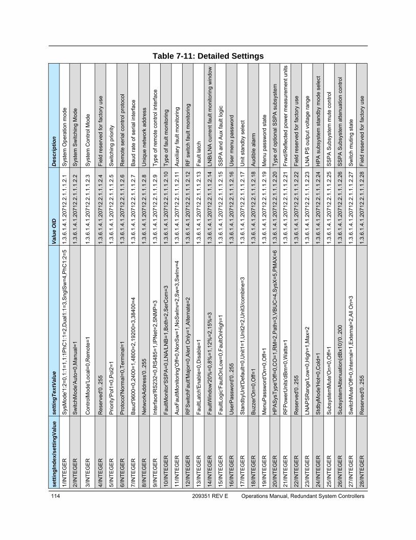
114 209351 REV E Operations Manual, Redundant System Controllers
setti
ngIn
dex/
setti
ngVa
lue
setti
ngTe
xtVa
lue
Valu
e O
ID
Des
crip
tion
1/IN
TEG
ER
Sys
Mod
e'1:
2=0,
1:1=
1,1:
1PhC
1:1=
2,D
ual1
:1=3
,Sng
lSw
=4,P
hC1:
2=5
1.3.
6.1.
4.1.
2071
2.2.
1.1.
1.2.
1 S
yste
m O
pera
tion
mod
e 2/
INTE
GE
R
Sw
itchM
ode'
Aut
o=0,
Man
ual=
1 1.
3.6.
1.4.
1.20
712.
2.1.
1.1.
2.2
Sys
tem
Sw
itchi
ng M
ode
3/IN
TEG
ER
Con
trolM
ode'
Loca
l=0,
Rem
ote=
1 1.
3.6.
1.4.
1.20
712.
2.1.
1.1.
2.3
Sys
tem
Con
trol M
ode
4/IN
TEG
ER
Res
erve
d'0.
.255
1.
3.6.
1.4.
1.20
712.
2.1.
1.1.
2.4
Fiel
d re
serv
ed fo
r fac
tory
use
5/
INTE
GE
R
Prio
rity'
Pol
1=0,
Pol
2=1
1.3.
6.1.
4.1.
2071
2.2.
1.1.
1.2.
5 S
witc
hing
prio
rity
6/IN
TEG
ER
Pro
toco
l'Nor
mal
=0,T
erm
inal
=1
1.3.
6.1.
4.1.
2071
2.2.
1.1.
1.2.
6 R
emot
e se
rial c
ontro
l pro
toco
l 7/
INTE
GE
R
Bau
d'96
00=0
,240
0=1,
4800
=2,1
9200
=3,3
8400
=4
1.3.
6.1.
4.1.
2071
2.2.
1.1.
1.2.
7 B
aud
rate
of s
eria
l int
erfa
ce
8/IN
TEG
ER
Net
wor
kAdd
ress
'0..2
55
1.3.
6.1.
4.1.
2071
2.2.
1.1.
1.2.
8 U
niqu
e ne
twor
k ad
dres
s 9/
INTE
GE
R
Inte
rface
'RS
232=
0,R
S48
5=1,
IPN
et=2
,SN
MP
=3
1.3.
6.1.
4.1.
2071
2.2.
1.1.
1.2.
9 Ty
pe o
f rem
ote
cont
rol i
nter
face
10
/INTE
GE
R
Faul
tMon
itor'S
SP
A=0
,LN
A/L
NB
=1,B
oth=
2,S
erC
om=3
1.
3.6.
1.4.
1.20
712.
2.1.
1.1.
2.10
Typ
e of
faul
t mon
itorin
g 11
/INTE
GE
R
Aux
Faul
tMon
itorin
g'O
ff=0,
Non
Sw
=1,N
oSw
Inv=
2,S
w=3
,Sw
Inv=
4 1.
3.6.
1.4.
1.20
712.
2.1.
1.1.
2.11
Aux
iliar
y fa
ult m
onito
ring
12/IN
TEG
ER
RFS
witc
hFau
lt'M
ajor
=0,A
lert
Onl
y=1,
Alte
rnat
e=2
1.3.
6.1.
4.1.
2071
2.2.
1.1.
1.2.
12 R
F sw
itch
faul
t mon
itorin
g 13
/INTE
GE
R
Faul
tLat
ch'E
nabl
e=0,
Dis
able
=1
1.3.
6.1.
4.1.
2071
2.2.
1.1.
1.2.
13 F
ault
latc
h 14
/INTE
GE
R
Faul
tWin
dow
'20%
=0,8
%=1
,12%
=2,1
5%=3
1.
3.6.
1.4.
1.20
712.
2.1.
1.1.
2.14
LN
B/L
NA
cur
rent
faul
t mon
itorin
g w
indo
w
15/IN
TEG
ER
Faul
tLog
ic'F
aultO
nLow
=0,F
aultO
nHig
h=1
1.3.
6.1.
4.1.
2071
2.2.
1.1.
1.2.
15 S
SP
A a
nd A
ux fa
ult l
ogic
16/IN
TEG
ER
Use
rPas
swor
d'0.
.255
1.
3.6.
1.4.
1.20
712.
2.1.
1.1.
2.16
Use
r men
u pa
ssw
ord
17/IN
TEG
ER
Sta
ndby
Uni
t'Def
ault=
0,U
nit1
=1,U
nit2
=2,U
nit3
/com
bine
=3
1.3.
6.1.
4.1.
2071
2.2.
1.1.
1.2.
17 U
nit s
tand
by s
elec
t 18
/INTE
GE
R
Buz
zer'O
n=0,
Off=
1 1.
3.6.
1.4.
1.20
712.
2.1.
1.1.
2.18
Aud
ible
ala
rm
19/IN
TEG
ER
Men
uPas
swor
d'O
n=0,
Off=
1 1.
3.6.
1.4.
1.20
712.
2.1.
1.1.
2.19
Men
u pa
ssw
ord
stat
e 20
/INTE
GE
R
HP
AS
ysTy
pe'O
ff=0,
CO
=1,R
M=2
,Pat
h=3,
VB
UC
=4,S
ysX
=5,P
MA
X=6
1.
3.6.
1.4.
1.20
712.
2.1.
1.1.
2.20
Typ
e of
opt
iona
l SS
PA
sub
syst
em
21/IN
TEG
ER
RFP
ower
Uni
ts'd
Bm
=0,W
atts
=1
1.3.
6.1.
4.1.
2071
2.2.
1.1.
1.2.
21 F
rwd/
Ref
lect
ed p
ower
mea
sure
men
t uni
ts
22/IN
TEG
ER
Res
erve
d'0.
.255
1.
3.6.
1.4.
1.20
712.
2.1.
1.1.
2.22
Fie
ld re
serv
ed fo
r fac
tory
use
23
/INTE
GE
R
LNA
PS
Ran
ge'L
ow=0
,Hig
h=1,
Max
=2
1.3.
6.1.
4.1.
2071
2.2.
1.1.
1.2.
23 L
NA
PS
out
put v
olta
ge ra
nge
24/IN
TEG
ER
Std
byM
ode'
Hot
=0,C
old=
1 1.
3.6.
1.4.
1.20
712.
2.1.
1.1.
2.24
HP
A s
ubsy
stem
sta
ndby
mod
e se
lect
25/IN
TEG
ER
Sub
syst
emM
ute'
On=
0,O
ff=1
1.3.
6.1.
4.1.
2071
2.2.
1.1.
1.2.
25 S
SP
A S
ubsy
stem
mut
e co
ntro
l 26
/INTE
GE
R
Sub
syst
emA
ttenu
atio
n(dB
x10)
'0..2
00
1.3.
6.1.
4.1.
2071
2.2.
1.1.
1.2.
26 S
SP
A S
ubsy
stem
atte
nuat
ion
cont
rol
27/IN
TEG
ER
Sw
itchM
ute'
Off=
0,In
tern
al=1
,Ext
erna
l=2,
All
On=
3 1.
3.6.
1.4.
1.20
712.
2.1.
1.1.
2.27
Sw
itch
mut
ing
stat
e
28/IN
TEG
ER
Res
erve
d'0.
.255
1.
3.6.
1.4.
1.20
712.
2.1.
1.1.
2.28
Fie
ld re
serv
ed fo
r fac
tory
use
Table 7-11: Detailed Settings
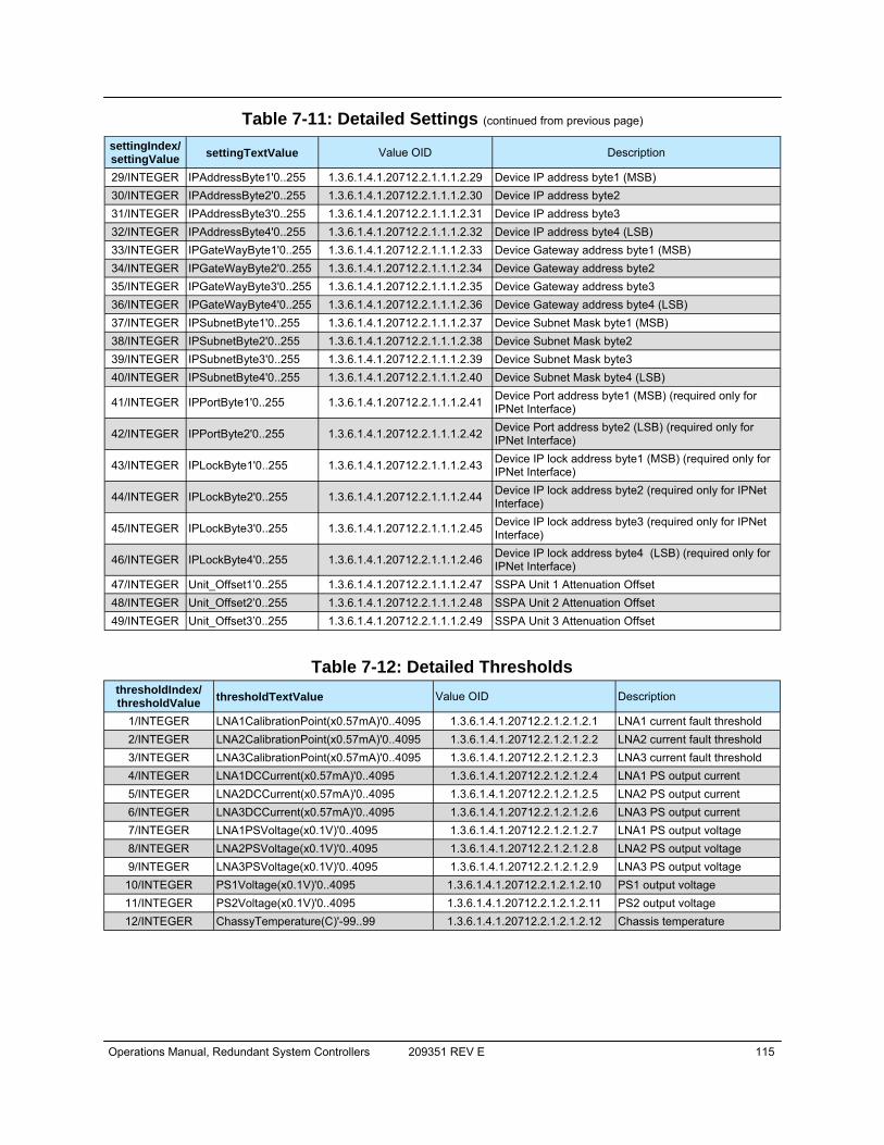
Operations Manual, Redundant System Controllers 209351 REV E 115
Table 7-11: Detailed Settings (continued from previous page) settingIndex/ settingValue settingTextValue Value OID Description
29/INTEGER IPAddressByte1'0..255 1.3.6.1.4.1.20712.2.1.1.1.2.29 Device IP address byte1 (MSB) 30/INTEGER IPAddressByte2'0..255 1.3.6.1.4.1.20712.2.1.1.1.2.30 Device IP address byte2 31/INTEGER IPAddressByte3'0..255 1.3.6.1.4.1.20712.2.1.1.1.2.31 Device IP address byte3 32/INTEGER IPAddressByte4'0..255 1.3.6.1.4.1.20712.2.1.1.1.2.32 Device IP address byte4 (LSB) 33/INTEGER IPGateWayByte1'0..255 1.3.6.1.4.1.20712.2.1.1.1.2.33 Device Gateway address byte1 (MSB) 34/INTEGER IPGateWayByte2'0..255 1.3.6.1.4.1.20712.2.1.1.1.2.34 Device Gateway address byte2 35/INTEGER IPGateWayByte3'0..255 1.3.6.1.4.1.20712.2.1.1.1.2.35 Device Gateway address byte3 36/INTEGER IPGateWayByte4'0..255 1.3.6.1.4.1.20712.2.1.1.1.2.36 Device Gateway address byte4 (LSB) 37/INTEGER IPSubnetByte1'0..255 1.3.6.1.4.1.20712.2.1.1.1.2.37 Device Subnet Mask byte1 (MSB) 38/INTEGER IPSubnetByte2'0..255 1.3.6.1.4.1.20712.2.1.1.1.2.38 Device Subnet Mask byte2 39/INTEGER IPSubnetByte3'0..255 1.3.6.1.4.1.20712.2.1.1.1.2.39 Device Subnet Mask byte3 40/INTEGER IPSubnetByte4'0..255 1.3.6.1.4.1.20712.2.1.1.1.2.40 Device Subnet Mask byte4 (LSB) 41/INTEGER IPPortByte1'0..255 1.3.6.1.4.1.20712.2.1.1.1.2.41 Device Port address byte1 (MSB) (required only for
IPNet Interface) 42/INTEGER IPPortByte2'0..255 1.3.6.1.4.1.20712.2.1.1.1.2.42 Device Port address byte2 (LSB) (required only for
IPNet Interface) 43/INTEGER IPLockByte1'0..255 1.3.6.1.4.1.20712.2.1.1.1.2.43 Device IP lock address byte1 (MSB) (required only for
IPNet Interface) 44/INTEGER IPLockByte2'0..255 1.3.6.1.4.1.20712.2.1.1.1.2.44 Device IP lock address byte2 (required only for IPNet
Interface) 45/INTEGER IPLockByte3'0..255 1.3.6.1.4.1.20712.2.1.1.1.2.45 Device IP lock address byte3 (required only for IPNet
Interface) 46/INTEGER IPLockByte4'0..255 1.3.6.1.4.1.20712.2.1.1.1.2.46 Device IP lock address byte4 (LSB) (required only for
IPNet Interface) 47/INTEGER Unit_Offset1’0..255 1.3.6.1.4.1.20712.2.1.1.1.2.47 SSPA Unit 1 Attenuation Offset 48/INTEGER Unit_Offset2’0..255 1.3.6.1.4.1.20712.2.1.1.1.2.48 SSPA Unit 2 Attenuation Offset 49/INTEGER Unit_Offset3’0..255 1.3.6.1.4.1.20712.2.1.1.1.2.49 SSPA Unit 3 Attenuation Offset
Table 7-12: Detailed Thresholds thresholdIndex/ thresholdValue thresholdTextValue Value OID Description
1/INTEGER LNA1CalibrationPoint(x0.57mA)'0..4095 1.3.6.1.4.1.20712.2.1.2.1.2.1 LNA1 current fault threshold 2/INTEGER LNA2CalibrationPoint(x0.57mA)'0..4095 1.3.6.1.4.1.20712.2.1.2.1.2.2 LNA2 current fault threshold 3/INTEGER LNA3CalibrationPoint(x0.57mA)'0..4095 1.3.6.1.4.1.20712.2.1.2.1.2.3 LNA3 current fault threshold 4/INTEGER LNA1DCCurrent(x0.57mA)'0..4095 1.3.6.1.4.1.20712.2.1.2.1.2.4 LNA1 PS output current 5/INTEGER LNA2DCCurrent(x0.57mA)'0..4095 1.3.6.1.4.1.20712.2.1.2.1.2.5 LNA2 PS output current 6/INTEGER LNA3DCCurrent(x0.57mA)'0..4095 1.3.6.1.4.1.20712.2.1.2.1.2.6 LNA3 PS output current 7/INTEGER LNA1PSVoltage(x0.1V)'0..4095 1.3.6.1.4.1.20712.2.1.2.1.2.7 LNA1 PS output voltage 8/INTEGER LNA2PSVoltage(x0.1V)'0..4095 1.3.6.1.4.1.20712.2.1.2.1.2.8 LNA2 PS output voltage 9/INTEGER LNA3PSVoltage(x0.1V)'0..4095 1.3.6.1.4.1.20712.2.1.2.1.2.9 LNA3 PS output voltage
10/INTEGER PS1Voltage(x0.1V)'0..4095 1.3.6.1.4.1.20712.2.1.2.1.2.10 PS1 output voltage 11/INTEGER PS2Voltage(x0.1V)'0..4095 1.3.6.1.4.1.20712.2.1.2.1.2.11 PS2 output voltage 12/INTEGER ChassyTemperature(C)'-99..99 1.3.6.1.4.1.20712.2.1.2.1.2.12 Chassis temperature
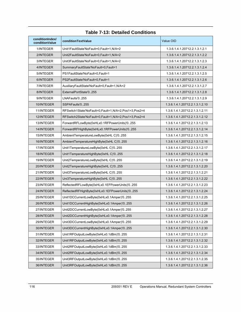
116 209351 REV E Operations Manual, Redundant System Controllers
Table 7-13: Detailed Conditions conditionIndex/ conditionValue conditionTextValue Value OID
1/INTEGER Unit1FaultState'NoFault=0,Fault=1,N/A=2 1.3.6.1.4.1.20712.2.1.3.1.2.1
2/INTEGER Unit2FaultState'NoFault=0,Fault=1,N/A=2 1.3.6.1.4.1.20712.2.1.3.1.2.2
3/INTEGER Unit3FaultState'NoFault=0,Fault=1,N/A=2 1.3.6.1.4.1.20712.2.1.3.1.2.3
4/INTEGER SummaryFaultState'NoFault=0,Fault=1 1.3.6.1.4.1.20712.2.1.3.1.2.4
5/INTEGER PS1FaultState'NoFault=0,Fault=1 1.3.6.1.4.1.20712.2.1.3.1.2.5
6/INTEGER PS2FaultState'NoFault=0,Fault=1 1.3.6.1.4.1.20712.2.1.3.1.2.6
7/INTEGER AuxiliaryFaultState'NoFault=0,Fault=1,N/A=2 1.3.6.1.4.1.20712.2.1.3.1.2.7
8/INTEGER ExternalPortState'0..255 1.3.6.1.4.1.20712.2.1.3.1.2.8
9/INTEGER LNAFaults'0..255 1.3.6.1.4.1.20712.2.1.3.1.2.9
10/INTEGER SSPAFaults'0..255 1.3.6.1.4.1.20712.2.1.3.1.2.10
11/INTEGER RFSwitch1State'NoFault=0,Fault=1,N/A=2,Pos1=3,Pos2=4 1.3.6.1.4.1.20712.2.1.3.1.2.11
12/INTEGER RFSwitch2State'NoFault=0,Fault=1,N/A=2,Pos1=3,Pos2=4 1.3.6.1.4.1.20712.2.1.3.1.2.12
13/INTEGER ForwardRFLowByte(0xHLx0.1RFPowerUnits)'0..255 1.3.6.1.4.1.20712.2.1.3.1.2.13
14/INTEGER ForwardRFHighByte(0xHLx0.1RFPowerUnits)'0..255 1.3.6.1.4.1.20712.2.1.3.1.2.14
15/INTEGER AmbientTemperatureLowByte(0xHL C)'0..255 1.3.6.1.4.1.20712.2.1.3.1.2.15
16/INTEGER AmbientTemperatureHighByte(0xHL C)'0..255 1.3.6.1.4.1.20712.2.1.3.1.2.16
17/INTEGER Unit1TemperatureLowByte(0xHL C)'0..255 1.3.6.1.4.1.20712.2.1.3.1.2.17
18/INTEGER Unit1TemperatureHighByte(0xHL C)'0..255 1.3.6.1.4.1.20712.2.1.3.1.2.18
19/INTEGER Unit2TemperatureLowByte(0xHL C)'0..255 1.3.6.1.4.1.20712.2.1.3.1.2.19
20/INTEGER Unit2TemperatureHighByte(0xHL C)'0..255 1.3.6.1.4.1.20712.2.1.3.1.2.20
21/INTEGER Unit3TemperatureLowByte(0xHL C)'0..255 1.3.6.1.4.1.20712.2.1.3.1.2.21
22/INTEGER Uni3TemperatureHighByte(0xHL C)'0..255 1.3.6.1.4.1.20712.2.1.3.1.2.22
23/INTEGER ReflectedRFLowByte(0xHLx0.1EFPowerUnits)'0..255 1.3.6.1.4.1.20712.2.1.3.1.2.23
24/INTEGER ReflectedRFHighByte(0xHLx0.1EFPowerUnits)'0..255 1.3.6.1.4.1.20712.2.1.3.1.2.24
25/INTEGER Unit1DCCurrentLowByte(0xHLx0.1Amper)'0..255 1.3.6.1.4.1.20712.2.1.3.1.2.25
26/INTEGER Unit1DCCurrentHighByte(0xHLx0.1Amper)'0..255 1.3.6.1.4.1.20712.2.1.3.1.2.26
27/INTEGER Unit2DCCurrentLowByte(0xHLx0.1Amper)'0..255 1.3.6.1.4.1.20712.2.1.3.1.2.27
28/INTEGER Unit2DCCurrentHighByte(0xHLx0.1Amper)'0..255 1.3.6.1.4.1.20712.2.1.3.1.2.28
29/INTEGER Unit3DCCurrentLowByte(0xHLx0.1Amper)'0..255 1.3.6.1.4.1.20712.2.1.3.1.2.29
30/INTEGER Unit3DCCurrentHighByte(0xHLx0.1Amper)'0..255 1.3.6.1.4.1.20712.2.1.3.1.2.30
31/INTEGER Unit1RFOutputLowByte(0xHLx0.1dBm)'0..255 1.3.6.1.4.1.20712.2.1.3.1.2.31
32/INTEGER Unit1RFOutputLowByte(0xHLx0.1dBm)'0..255 1.3.6.1.4.1.20712.2.1.3.1.2.32
33/INTEGER Unit2RFOutputLowByte(0xHLx0.1dBm)'0..255 1.3.6.1.4.1.20712.2.1.3.1.2.33
34/INTEGER Unit2RFOutputLowByte(0xHLx0.1dBm)'0..255 1.3.6.1.4.1.20712.2.1.3.1.2.34
35/INTEGER Unit3RFOutputLowByte(0xHLx0.1dBm)'0..255 1.3.6.1.4.1.20712.2.1.3.1.2.35
36/INTEGER Unit3RFOutputLowByte(0xHLx0.1dBm)'0..255 1.3.6.1.4.1.20712.2.1.3.1.2.36
Operations Manual, Redundant System Controllers 209351 REV E 117
7.6.4.2 SNMP V3 Issues in Teledyne Paradise Datacom RCP2 Controller Simple Network Management Protocol (SNMP) is an interoperable standards-based protocol that allows for external monitoring of the Content Engine through an SNMP agent. A SNMP-managed network consists of three primary components: managed devices, agents, and management systems. A managed device is a network node that contains a SNMP agent and resides on a managed network. Managed devices collect and store management information and use SNMP to make this information available to manage-ment systems that use SNMP. Managed devices include routers, servers, switches, bridges hubs, computer hosts, and printers. An agent is a software module that has local knowledge of management information and translates that information into a form compatible with SNMP: the Management Information Base (MIB). The agent can send traps, or notification of certain events, to the manager. Essentially, a Teledyne Paradise Datacom SSPA is considered a “SNMP agent”. A manager is a software module that listens to the SNMP notifications sent by SNMP agents. The manager can also send requests to an agent to collect remote information from the Management Information Base (MIB). The communication between the agent and the manager uses the SNMP protocol, which is an application of the ASN.1 BER (Abstract Syntax Notation 1 with Basic En-coding Rules), typically over UDP (for IP networks).
• Version 1 (SNMPv1, described in RFC 1157) is the initial implementation of SNMP.
• Version 2 (SNMPv2c, described in RFC 1902) is the second release of SNMP. It provides additions to data types, counter size, and protocol op-erations.
• Version 3 (SNMPv3, described in RFC 2271 through RFC 2275) is the most recent version of SNMP.
SNMP V1 SNMP version 1 (SNMPv1) is the initial implementation of the SNMP protocol. SNMPv1 operates over protocols such as User Datagram Protocol (UDP), Internet Protocol (IP), OSI Connectionless Network Service (CLNS), AppleTalk Datagram- De-livery Protocol (DDP), and Novell Internet Packet Exchange (IPX). SNMPv1 is widely used and is the de-facto network-management protocol in the Internet community. The Teledyne Paradise Datacom RCP2 family of products utilizes the most popular im-plementation, SNMP V1 over UDP transport layer.
118 209351 REV E Operations Manual, Redundant System Controllers
SNMP V2 SNMPv2 (RFC 1441–RFC 1452) revises version 1 and includes some improvements in the areas of performance, security, confidentiality, and manager-to-manager com-munications. It introduced GetBulkRequest, an alternative to iterative GetNextRe-quests for retrieving large amounts of management data in a single request. However, the new party-based security system in SNMPv2, viewed by many as overly complex, was not widely accepted. The format of the trap message was also changed in SNMPv2. To avoid these compat-ibility issues, the trap mechanism was not implemented in the Teledyne Paradise Data-com SSPA MIB. SNMP V3 Although SNMPv3 makes no changes to the protocol aside from the addition of crypto-graphic security, it looks much different due to new textual conventions, concepts, and terminology. SNMPv3 primarily added security and remote configuration enhance-ments to SNMP. Many embedded controllers and microprocessors that are used in electronic components such as amplifier modules do not have support for SNMP V2 or V3. This is due to the extensive memory resources required by the computation inten-sive cryptographic security of SNMP V3. For this reason V3 has not gained widespread support amongst embedded MCU plat-form manufacturers. Existing port implementations are limited to very powerful ARM5 or above cores, running under full-scale OS systems (Linux, Android, etc.). At large, these configurations require external bulk RAM/FLASH to operate. This requirement ultimately affects the minimum device startup time (tens of seconds, due to the large boot BIOS) and working temperature range (mostly indoor). As noted in Cisco’s release notes about SNMP V3:
SNMP no fica ons can be sent as traps or inform requests. Traps are unreliable because the re-ceiver does not send acknowledgments when this device receives traps. The sender cannot deter-mine if the traps were received. However, an SNMP en ty that receives an inform request acknowledges the message with an SNMP response protocol data unit (PDU). If the sender never receives the response, the inform request can be sent again. Therefore, informs are more likely to reach their intended des na on. However, informs consume more resources in the agent and in the network. Unlike a trap, which is discarded as soon as it is sent, an inform request must be held in memory un l a response is re-ceived, or the request mes out. Traps are sent only once, while an inform can be retried several
mes. The retries increase traffic and contribute to a higher overhead on the network. (http://www.cisco.com/c/en/us/support/docs/ip/simple-network-management-protocol-snmp/13506-snmp-traps.html, last visited on 22 January 2015.)

Operations Manual, Redundant System Controllers 209351 REV E 119
7.6.4.3 SNMP MIB Tree --paradiseDatacom(1.3.6.1.4.1.20712) | +--deviceINFO(1) | | | +-- r-n OctetString deviceID(1) | +-- rwn OctetString deviceLocation(2) | +-- r-n OctetString deviceRevision(3) | +-- r-n Enumeration deviceType(4) | +--devices(2) | +--paradiseDevice(1) | | | +--settings(1) | | | | | +--settingsEntry(1) [settingIndex] | | | | | +-- rwn Integer32 settingIndex(1) | | +-- rwn Integer32 settingValue(2) | | +-- r-n OctetString settingTextValue(3) | | | +--thresholds(2) | | | | | +--thresholdsEntry(1) [thresholdIndex] | | | | | +-- rwn Integer32 thresholdIndex(1) | | +-- r-n Integer32 thresholdValue(2) | | +-- r-n Enumeration thresholdStatus(3) | | +-- r-n OctetString thresholdText(4) | | | +--conditions(3) | | | +--conditionsEntry(1) [conditionsIndex] | | | +-- rwn Integer32 conditionsIndex(1) | +-- r-n Integer32 conditionsValue(2) | +-- r-n Counter conditionsEventCount(3) | +-- r-n OctetString conditionsText(4) | +--paradiseDeviceA(2) | +--paradiseDeviceB(3) | +--paradiseDeviceC(4) | +--modem(5)

120 209351 REV E Operations Manual, Redundant System Controllers
7.6.4.4 Description of MIB Entities deviceINFO — This field includes general device information. deviceID — Octet string type; maximum length -60; field specifies device model and
serial number; read only access; OID -1.3.6.1.4.1.20712.1.1 deviceLocation — Octet string type; maximum length 60; filed allow customer to store
information about device physical location or any other textual information relat-ed to the device; read/write access; OID -1.3.6.1.4.1.20712.1.2
deviceRevision — Octet string type; maximum length 60; field specifies device firm-
ware revision; read only access; OID -1.3.6.1.4.1.20712.1.3 deviceType — Enumeration, integer type; field allows simple detection of SNMP
device type. Values: rmsspa(1), cosspa(2), rcp2fprc(3), rcp21000rm(4), rcp21000co(5), rcp21000rcp(6), buc(7), rbc(8), minicosspa(9); read/write ac-cess. Setting the ID to any other value will default type to cosspa. OID -1.3.6.1.4.1.20712.1.4
devices — This field is subdivided into 5 branches: paradiseDevice, paradiseDeviceA,
paradiseDeviceB, paradiseDeviceC and modem. The paradiseDevice branch currently is used for all Paradise Datacom LLC SNMP enabled device except Modem. See the Evolution Modem manual for specific MIB information for mo-dems. Branches for Device A, B and C are reserved for future use.
paradiseDevice — Field contents tables hold specific device information: Settings,
Thresholds and Conditions. All table formats follow a common pattern: Index, Value, TextValue. The threshold table has an additional column for parameter validation. The conditions table has an extra column for event counters.
The Index column provides general table indexing; the Value column presents the current value of the relevant parameter; the TextValue column provides information about parameter name, measurement units and limits. Value “1” in the validation column of the thresholds table indicates that relevant parameter is valid under the current system configuration; value “2” indicates that parameter is invalid or “Not available”. The event counter column of the conditions table indicates how many times a value of a relevant parameter changed its state since system power-up.
settings — Table contents current device configuration and provides device manage-
ment. For detailed settings table info for SNMP device see Table 7-11 . Read/write access for settingsValue column.

Operations Manual, Redundant System Controllers 209351 REV E 121
thresholds — Table provides information about device internal limits and subsystems info. For detailed table information refer to Table 7-12. Read only access.
conditions — Table contents device fault status information. Read only access. For
detailed conditions table info see Table 7-13. 7.6.4.5 Configuring RCP2 Unit to Work With SNMP Protocol
1. Set up the unit IP address. Press the Main Menu key on the front panel; se-lect 2.Com.Setup and press the Enter key; select 5.IP Setup and press the Enter key; select 2.LocalIP and press the Enter key. Use the navigation keys to adjust the unit IP address. A single controller in a system has a de-fault address of 192.168.0.9. Press the Enter key when complete;
2. Set up the unit gateway address. Press the Main Menu key; select 2.Com.Setup and press the Enter key; select 5.IP Setup and press the En-ter key; select 4.Gateway and press the Enter key. Use the navigation keys to adjust the unit gateway address. If no gateway is needed, set the address to 0.0.0.0. Press the Enter key when complete;
3. Set up the unit subnet mask. Press the Main Menu key; select 2.Com.Setup and press the Enter key; select 5.IP Setup and press the Enter key; select 3.Subnet and press the Enter key. Use the navigation keys to adjust the unit subnet mask. Press the Enter key when complete;
4. Set up the unit Community Set and Get strings. Press the Main Menu key; select 2.Com.Setup and press the Enter key; select 5.IP Setup and press the Enter key; select 6.More and press the Enter key; select 1.CommunitySet (or 2.CommunityGet). Using the navigation keys to adjust the unit community strings information. Press and hold the key for typematic option. Press the Enter key when complete. To erase unwanted characters, press and hold the Down Arrow (▼) key and then press the Up Arrow (▲);
5. Set up the unit interface to SNMP. Press the Main Menu key; select 2.Com.Setup and press the Enter key; select 4.Interface and press the En-ter key; select 4.SNMP and press the Enter key.
6. SNMP protocol now is set and ready to be used.
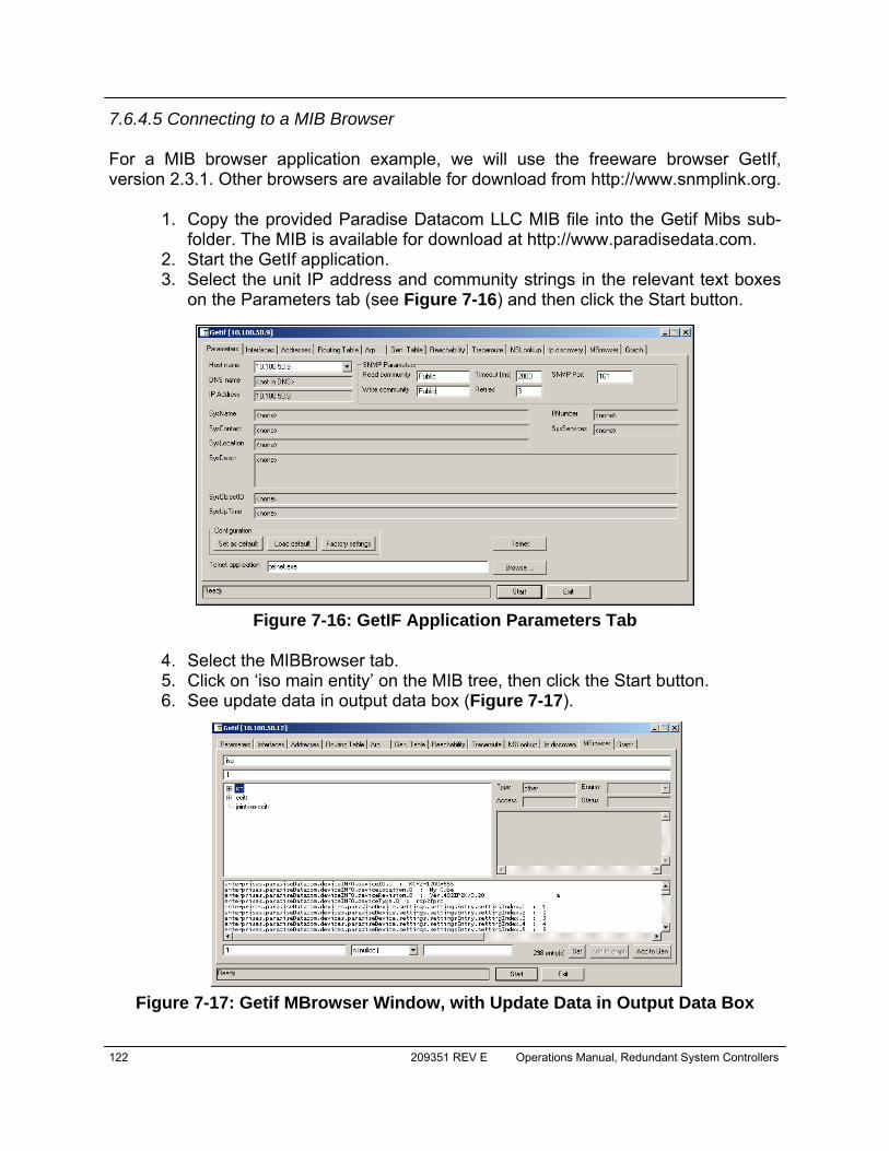
122 209351 REV E Operations Manual, Redundant System Controllers
7.6.4.5 Connecting to a MIB Browser For a MIB browser application example, we will use the freeware browser GetIf, version 2.3.1. Other browsers are available for download from http://www.snmplink.org.
1. Copy the provided Paradise Datacom LLC MIB file into the Getif Mibs sub-folder. The MIB is available for download at http://www.paradisedata.com.
2. Start the GetIf application. 3. Select the unit IP address and community strings in the relevant text boxes
on the Parameters tab (see Figure 7-16) and then click the Start button.
4. Select the MIBBrowser tab. 5. Click on ‘iso main entity’ on the MIB tree, then click the Start button. 6. See update data in output data box (Figure 7-17).
Figure 7-16: GetIF Application Parameters Tab
Figure 7-17: Getif MBrowser Window, with Update Data in Output Data Box
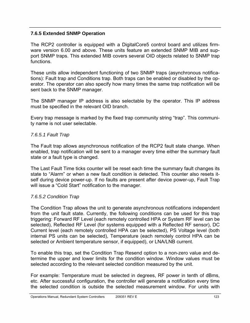
Operations Manual, Redundant System Controllers 209351 REV E 123
7.6.5 Extended SNMP Operation The RCP2 controller is equipped with a DigitalCore5 control board and utilizes firm-ware version 6.00 and above. These units feature an extended SNMP MIB and sup-port SNMP traps. This extended MIB covers several OID objects related to SNMP trap functions. These units allow independent functioning of two SNMP traps (asynchronous notifica-tions): Fault trap and Conditions trap. Both traps can be enabled or disabled by the op-erator. The operator can also specify how many times the same trap notification will be sent back to the SNMP manager. The SNMP manager IP address is also selectable by the operator. This IP address must be specified in the relevant OID branch. Every trap message is marked by the fixed trap community string “trap”. This communi-ty name is not user selectable. 7.6.5.1 Fault Trap The Fault trap allows asynchronous notification of the RCP2 fault state change. When enabled, trap notification will be sent to a manager every time either the summary fault state or a fault type is changed. The Last Fault Time ticks counter will be reset each time the summary fault changes its state to “Alarm” or when a new fault condition is detected. This counter also resets it-self during device power-up. If no faults are present after device power-up, Fault Trap will issue a “Cold Start” notification to the manager. 7.6.5.2 Condition Trap The Condition Trap allows the unit to generate asynchronous notifications independent from the unit fault state. Currently, the following conditions can be used for this trap triggering: Forward RF Level (each remotely controlled HPA or System RF level can be selected), Reflected RF Level (for systems equipped with a Reflected RF sensor), DC Current level (each remotely controlled HPA can be selected), PS Voltage level (both internal PS units can be selected), Temperature (each remotely control HPA can be selected or Ambient temperature sensor, if equipped), or LNA/LNB current. To enable this trap, set the Condition Trap Resend option to a non-zero value and de-termine the upper and lower limits for the condition window. Window values must be selected according to the relevant selected condition measured by the unit. For example: Temperature must be selected in degrees, RF power in tenth of dBms, etc. After successful configuration, the controller will generate a notification every time the selected condition is outside the selected measurement window. For units with

124 209351 REV E Operations Manual, Redundant System Controllers
multiple measured parameters, the relevant condition location must be selected (i.e., units with two power supplies use 1 for PS1, and 2 for PS2). For other conditions, this value is “don’t care”. Both traps will send a “Device Up Time” time stamp with every trap notification. 7.6.5.3 Extended SNMP MIB Tree --paradiseDatacom(1.3.6.1.4.1.20712) | +--deviceINFO((1.3.6.1.4.1.20712.1) | | | +-- r-n OctetString deviceID(1.3.6.1.4.1.20712.1.1) | +-- rwn OctetString deviceLocation(1.3.6.1.4.1.20712.1.2) | +-- r-n OctetString deviceRevision(1.3.6.1.4.1.20712.1.3) | +-- r-n Enumeration deviceType(1.3.6.1.4.1.20712.1.4) | +--deviceTimeTicks(1.3.6.1.4.1.20712.1.5) | | | | | +-- r-n TimeTicks deviceUpTime(1.3.6.1.4.1.20712.1.5.1) | | +-- r-n TimeTicks deviceFaultTime(1.3.6.1.4.1.20712.1.5.2) | | | +--deviceCounters(1.3.6.1.4.1.20712.1.6) | | | | | +-- r-n Counter deviceSFaultCounter(1) | | | +--deviceFaultState(1.3.6.1.4.1.20712.1.7) | | | | | +-- r-n Enumeration deviceSummaryFault(1) | | +-- r-n Enumeration deviceLastFault(2) | | | +--deviceTrapedCondition(1.3.6.1.4.1.20712.1.8) | | | | | +-- r-n Integer32 deviceTrappedConditionValue(1) | | | +--deviceTrapControl(1.3.6.1.4.1.20712.1.9) | | | | | +-- rwn IpAddress deviceManagerIP(1) | | +-- rwn Integer32 deviceFaultsTrapResend(2) | | +-- rwn Integer32 deviceConditionTrapResend(3) | | +-- rwn Enumeration deviceConditionToMonitor(4) | | +-- rwn Integer32 deviceConditionULimit(5) | | +-- rwn Integer32 deviceConditionLLimit(6) | | +-- rwn Integer32 deviceConditionLocation(7) | | | +--deviceTraps(1.3.6.1.4.1.20712.1.10) | | | +-- (1.3.6.1.4.1.20712.1.10.0) | | | +--deviceFaultsTrap(1.3.6.1.4.1.20712.1.10.0.11) | [deviceUpTime,deviceSummaryFault,deviceLastFault] | | | +--deviceConditionTrap(1.3.6.1.4.1.20712.1.10.0.12) | [deviceUpTime,deviceConditionToMonitor,deviceTrappedConditionValue] (continued)

Operations Manual, Redundant System Controllers 209351 REV E 125
| +--devices(2) | +--paradiseDevice(1) | | | +--settings(1) | | | | | +--settingsEntry(1) [settingIndex] | | | | | +-- rwn Integer32 settingIndex(1) | | +-- rwn Integer32 settingValue(2) | | +-- r-n OctetString settingTextValue(3) | | | +--thresholds(2) | | | | | +--thresholdsEntry(1) [thresholdIndex] | | | | | +-- rwn Integer32 thresholdIndex(1) | | +-- r-n Integer32 thresholdValue(2) | | +-- r-n Enumeration thresholdStatus(3) | | +-- r-n OctetString thresholdText(4) | | | +--conditions(3) | | | +--conditionsEntry(1) [conditionsIndex] | | | +-- rwn Integer32 conditionsIndex(1) | +-- r-n Integer32 conditionsValue(2) | +-- r-n Counter conditionsEventCount(3) | +-- r-n OctetString conditionsText(4) | +--paradiseDeviceA(2) | +--paradiseDeviceB(3) | +--paradiseDeviceC(4) | +--modem(5)
126 209351 REV E Operations Manual, Redundant System Controllers
7.6.5.4 Extended SNMP MIB Tree Elements in Detail deviceRevision — Octet string type; maximum length 60; field specifies device firm-
ware revision; read only access; OID -1.3.6.1.4.1.20712.1.3 deviceUpTime — Device total up time in hundredths of a second; OID -
1.3.6.1.4.1.20712.1.5.1 deviceFaultTime — Time elapsed since last state change of deviceLastFault parame-
ter in hundredths of second; OID - 1.3.6.1.4.1.20712.1.5.2 deviceSFaultCounter — Counts number of Summary alarms since device power up;
OID - 1.3.6.1.4.1.20712.1.6.1 deviceSummaryFault — Enumerated value of device last detected fault condition.
The following enumerated values are possible: coldStart(1), overTemp(2), badRegltr(3), lowDCCur(4), aux(5), buc(6), lna(7), hpa(8), lowFwdRF(9), high-RefRF(10), nPlusOne (11), badPS(12), timeOut(13), other(14), noFaults(15). OID - 1.3.6.1.4.1.20712.1.7.1
deviceTrappedConditionValue — Condition value trapped by deviceConditionTrap;
OID - 1.3.6.1.4.1.20712.1.8.1 deviceManagerIP — Trap recipient IP address; OID - 1.3.6.1.4.1.20712.1.9.1 deviceFaultsTrapResend — Defines how many times deviceFaultsTrap will repeat
the message. 0 - Disables trap triggering; OID - 1.3.6.1.4.1.20712.1.9.2 deviceConditionTrapResend — Defines how many times condition trap will repeat
the message. 0 - Disables trap triggering; OID - 1.3.6.1.4.1.20712.1.9.3 deviceConditionToMonitor — Enumerated value. Object defines which condition to
trap. The following enumerations are possible: fwdRF(1), dcCurrent(2), volt-agePS(3), temperature( 4), lnaCur(5), refRF(6); OID - 1.3.6.1.4.1.20712.1.9.4
deviceConditionULimit — Conditions upper trap limit. Trap will be sent when the con-
dition exceeds this limit. OID - 1.3.6.1.4.1.20712.1.9.5 deviceConditionLLimit — Conditions lower trap limit. Trap will be sent when condi-
tion falls below this limit. OID - 1.3.6.1.4.1.20712.1.9.6
Operations Manual, Redundant System Controllers 209351 REV E 127
deviceConditionLocation — Parameter specifying condition measuring location in device containing multiple location of the same type (multiple PS, HPAs, LNAs etc.). Set to 0 for system-wide conditions, 1 .. n for relevant unit. For devices with single condition location parameter is “don’t care”, for system wide parame-ters (System RF power, Ambient temperature etc. select 4). OID - 1.3.6.1.4.1.20712.1.9.7
deviceFaultsTrap — Trap fires deviceFaultsTrapResend times when deviceLastFault
or deviceSummaryFault state changes. OID - 1.3.6.1.4.1.20712.1.10.0.11

128 209351 REV E Operations Manual, Redundant System Controllers
THIS PAGE LEFT INTENTIONALLY BLANK

Operations Manual, Redundant System Controllers 209351 REV E 129
Section 8: Maintenance Switch Controller
8.0 Introduction Teledyne Paradise Datacom offers the option of utilizing the RCP2-1100 controller as a Maintenance Switch Controller, which controls the position of a single waveguide switch. A Maintenance Switch Controller is typically connected to the switch drive via a single cable. With systems using amplifiers of certain high power levels, the controller could also be connected to the system SSPAs, so that the output of the amplifiers can be temporarily muted during switchover to prevent arcing in the transmission line. 8.1 Operation Modes The Maintenance Switch Controller controls the position of a switch at the output of the connected amplifier or amplifier system. The position of the switch determines whether the output signal of the amplifier or amplifier system is directed to a dummy load (the maintenance position), or to the system output. 8.1.1 Directing the Output Signal to the System Output When the operator presses the POS1 key on the controller front panel, the switch is set to its primary position. The LED on the POS1 key will illuminate and the LEDs in the mimic path display will show the signal directed to the system output. See Figure 8-1.
8.1.2 Directing the Output Signal to the Dummy Load When the operator presses the POS2 key on the controller front panel, the switch is set to its secondary position. The LED on the POS2 key will illuminate and the LEDs in the mimic path display will show the signal directed to the termination. See Figure 8-2.
Figure 8-1: POS1 key to direct output signal to system output
Figure 8-2: POS2 key to direct output signal to dummy load
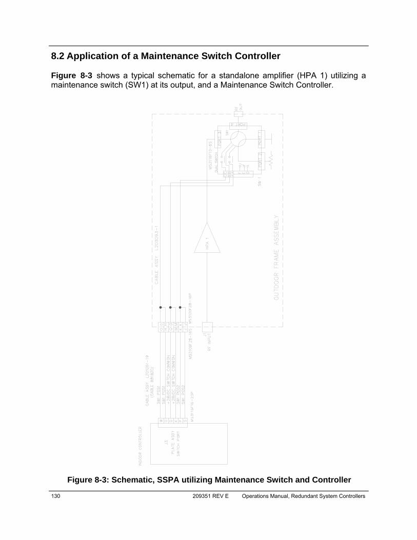
130 209351 REV E Operations Manual, Redundant System Controllers
8.2 Application of a Maintenance Switch Controller Figure 8-3 shows a typical schematic for a standalone amplifier (HPA 1) utilizing a maintenance switch (SW1) at its output, and a Maintenance Switch Controller.
Figure 8-3: Schematic, SSPA utilizing Maintenance Switch and Controller
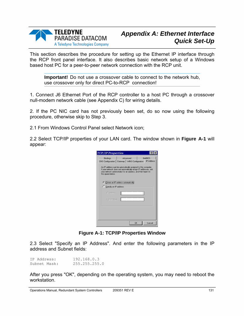
Operations Manual, Redundant System Controllers 209351 REV E 131
This section describes the procedure for setting up the Ethernet IP interface through the RCP front panel interface. It also describes basic network setup of a Windows based host PC for a peer-to-peer network connection with the RCP unit.
Important! Do not use a crossover cable to connect to the network hub, use crossover only for direct PC-to-RCP connection!
1. Connect J6 Ethernet Port of the RCP controller to a host PC through a crossover null-modem network cable (see Appendix C) for wiring details. 2. If the PC NIC card has not previously been set, do so now using the following procedure, otherwise skip to Step 3. 2.1 From Windows Control Panel select Network icon; 2.2 Select TCP/IP properties of your LAN card. The window shown in Figure A-1 will appear:
2.3 Select "Specify an IP Address". And enter the following parameters in the IP address and Subnet fields: IP Address: 192.168.0.3 Subnet Mask: 255.255.255.0
After you press "OK", depending on the operating system, you may need to reboot the workstation.
Figure A-1: TCP/IP Properties Window
Appendix A: Ethernet Interface Quick Set-Up

132 209351 REV E Operations Manual, Redundant System Controllers
2.4 After optional reboot, open the Command Prompt console window and enter: C:\>IPCONFIG
This will display the IP settings: 0 Ethernet Adapter: IP Address: 192.168.0.3 Subnet Mask: 255.255.255.0 Default Gateway: 2.5 You can now try to Ping your PC: In Command Prompt window enter the following: C:\>ping 192.168.0.3
This will display: Pinging 192.168.0.3 with 32 bytes of data: Reply from 192.168.0.3: bytes=32 time<10ms TTL=128 Reply from 192.168.0.3: bytes=32 time<10ms TTL=128 Reply from 192.168.0.3: bytes=32 time<10ms TTL=128 Reply from 192.168.0.3: bytes=32 time<10ms TTL=128 Ping statistics for 192.168.0.3: Packets: Sent=4, Received=4, Lost=0 (0%loss), Approximate round trip times in milli-seconds: Minimum=0ms, Maximum=0ms, Average=0ms
Your network LAN card is now set up. 3. On the RCP unit front panel, perform the following sequence: Press the Main Menu key; select 2.Com.Setup and press the Enter key; select 5.IPSetup and press the Enter key; select 2.LocalIP and press the Enter key. Enter the address 192.168.0.0 by using the navigation keys. Press the Enter key to accept the entered value. Use the same menu pattern above to set the following parameters: Subnet: 255.255.255.0; Gateway: 0.0.0.0; IPLock: 255.255.255.255; IPPort: 1038. Verify the selected parameters by navigating to the 1.IPInfo screen.
Operations Manual, Redundant System Controllers 209351 REV E 133
4. On the RCP unit front panel select sequentially: Press the Main Menu key; select 2.Com.Setup and press the Enter key; select 4.Interface and press the Enter key; select 3.IPNet and press the Enter key. The RCP unit is now set up to work with Ethernet Interface. You may now ping the RCP unit from the host PC: C:\>ping 192.168.0.0
This will display: Pinging 192.168.0.0 with 32 bytes of data: Reply from 192.168.0.0: bytes=32 time<10ms TTL=128 Reply from 192.168.0.0: bytes=32 time<10ms TTL=128 Reply from 192.168.0.0: bytes=32 time<10ms TTL=128 Reply from 192.168.0.0: bytes=32 time<10ms TTL=128 Ping statistics for 192.168.0.3: Packets: Sent=4, Received=4, Lost=0 (0%loss), Approximate round trip times in milli-seconds: Minimum=0ms, Maximum=0ms, Average=0ms
5. Run the Teledyne Paradise Datacom Universal M&C package on the host PC to check all M&C functions. Refer to Appendix E for details. When prompted, select an Internet connection to the unit using IP Address 192.168.0.0, local port address to 1039 and remote port address to 1038. The RCP is now connected to your host work-station for remote M&C.

134 209351 REV E Operations Manual, Redundant System Controllers
THIS PAGE LEFT INTENTIONALLY BLANK

Operations Manual, Redundant System Controllers 209351 REV E 135
This section briefly describes the basic theory related to the physical layer of 10/100 Base-T networking, as well as proper wiring techniques. There are several classifications of cable used for twisted-pair networks. Recommend-ed cable for all new installations is Category 5 (or CAT 5). CAT 5 cable has four twist-ed pairs of wire for a total of eight individually insulated wires. Each pair is color coded with one wire having a solid color (blue, orange, green, or brown) twisted around a second wire with a white background and a stripe of the same color. The solid colors may have a white stripe in some cables. Cable colors are commonly described us-ing the background color followed by the color of the stripe; e.g., white-orange is a ca-ble with a white background and an orange stripe. The straight through and crossover patch cables are terminated with CAT 5 RJ-45 modular plugs. RJ-45 plugs are similar to those you'll see on the end of your tel-ephone cable except they have eight versus four or six contacts on the end of the plug and they are about twice as big. Make sure they are rated for CAT 5 wiring. (RJ means "Registered Jack"). A special Modular Plug Crimping Tool (such as that shown in Figure B-1) is needed for proper wiring.
The 10BASE-T and 100BASE-TX Ethernets consist of two transmission lines. Each transmission line is a pair of twisted wires. One pair receives data signals and the oth-er pair transmits data signals. A balanced line driver or transmitter is at one end of one of these lines and a line receiver is at the other end. A simplified schematic for one of these lines and its transmitter and receiver is shown in Figure B-2.
Figure B-1: Modular Plug Crimping Tool
Figure B-2: Transmission Line
Appendix B: Proper 10/100 Base-T Ethernet Cable Wiring
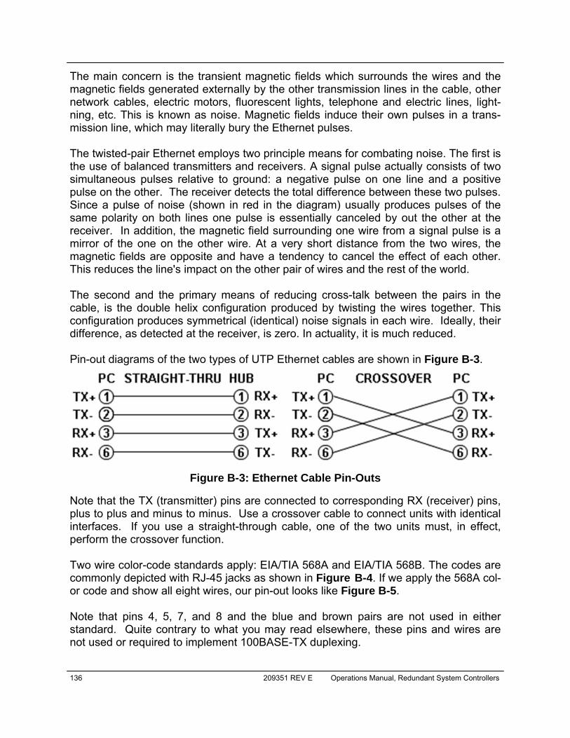
136 209351 REV E Operations Manual, Redundant System Controllers
The main concern is the transient magnetic fields which surrounds the wires and the magnetic fields generated externally by the other transmission lines in the cable, other network cables, electric motors, fluorescent lights, telephone and electric lines, light-ning, etc. This is known as noise. Magnetic fields induce their own pulses in a trans-mission line, which may literally bury the Ethernet pulses. The twisted-pair Ethernet employs two principle means for combating noise. The first is the use of balanced transmitters and receivers. A signal pulse actually consists of two simultaneous pulses relative to ground: a negative pulse on one line and a positive pulse on the other. The receiver detects the total difference between these two pulses. Since a pulse of noise (shown in red in the diagram) usually produces pulses of the same polarity on both lines one pulse is essentially canceled by out the other at the receiver. In addition, the magnetic field surrounding one wire from a signal pulse is a mirror of the one on the other wire. At a very short distance from the two wires, the magnetic fields are opposite and have a tendency to cancel the effect of each other. This reduces the line's impact on the other pair of wires and the rest of the world. The second and the primary means of reducing cross-talk between the pairs in the cable, is the double helix configuration produced by twisting the wires together. This configuration produces symmetrical (identical) noise signals in each wire. Ideally, their difference, as detected at the receiver, is zero. In actuality, it is much reduced. Pin-out diagrams of the two types of UTP Ethernet cables are shown in Figure B-3.
Note that the TX (transmitter) pins are connected to corresponding RX (receiver) pins, plus to plus and minus to minus. Use a crossover cable to connect units with identical interfaces. If you use a straight-through cable, one of the two units must, in effect, perform the crossover function. Two wire color-code standards apply: EIA/TIA 568A and EIA/TIA 568B. The codes are commonly depicted with RJ-45 jacks as shown in Figure B-4. If we apply the 568A col-or code and show all eight wires, our pin-out looks like Figure B-5. Note that pins 4, 5, 7, and 8 and the blue and brown pairs are not used in either standard. Quite contrary to what you may read elsewhere, these pins and wires are not used or required to implement 100BASE-TX duplexing.
Figure B-3: Ethernet Cable Pin-Outs
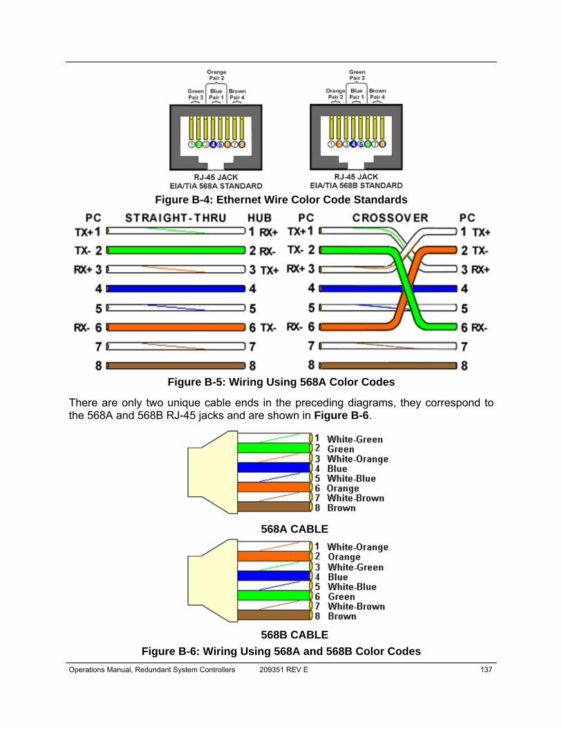
Operations Manual, Redundant System Controllers 209351 REV E 137
There are only two unique cable ends in the preceding diagrams, they correspond to the 568A and 568B RJ-45 jacks and are shown in Figure B-6.
Figure B-4: Ethernet Wire Color Code Standards
Figure B-5: Wiring Using 568A Color Codes
Figure B-6: Wiring Using 568A and 568B Color Codes
568A CABLE
568B CABLE
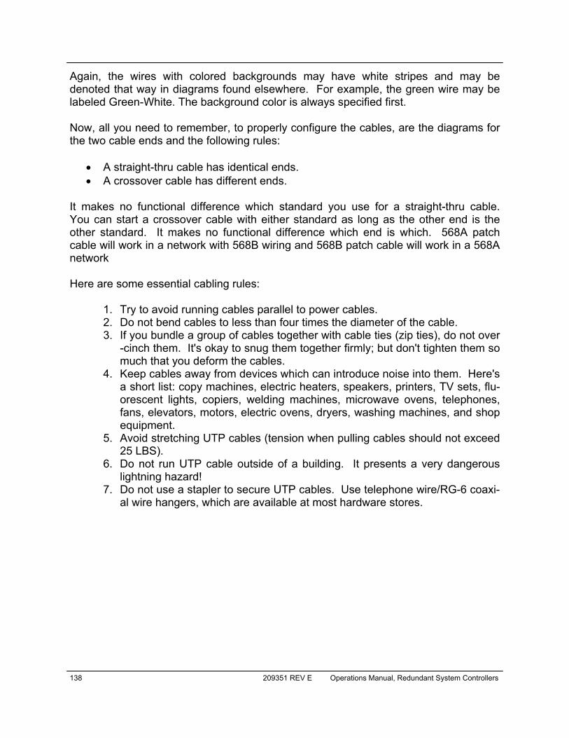
138 209351 REV E Operations Manual, Redundant System Controllers
Again, the wires with colored backgrounds may have white stripes and may be denoted that way in diagrams found elsewhere. For example, the green wire may be labeled Green-White. The background color is always specified first. Now, all you need to remember, to properly configure the cables, are the diagrams for the two cable ends and the following rules:
• A straight-thru cable has identical ends. • A crossover cable has different ends.
It makes no functional difference which standard you use for a straight-thru cable. You can start a crossover cable with either standard as long as the other end is the other standard. It makes no functional difference which end is which. 568A patch cable will work in a network with 568B wiring and 568B patch cable will work in a 568A network Here are some essential cabling rules:
1. Try to avoid running cables parallel to power cables. 2. Do not bend cables to less than four times the diameter of the cable. 3. If you bundle a group of cables together with cable ties (zip ties), do not over
-cinch them. It's okay to snug them together firmly; but don't tighten them so much that you deform the cables.
4. Keep cables away from devices which can introduce noise into them. Here's a short list: copy machines, electric heaters, speakers, printers, TV sets, flu-orescent lights, copiers, welding machines, microwave ovens, telephones, fans, elevators, motors, electric ovens, dryers, washing machines, and shop equipment.
5. Avoid stretching UTP cables (tension when pulling cables should not exceed 25 LBS).
6. Do not run UTP cable outside of a building. It presents a very dangerous lightning hazard!
7. Do not use a stapler to secure UTP cables. Use telephone wire/RG-6 coaxi-al wire hangers, which are available at most hardware stores.

Operations Manual, Redundant System Controllers 209351 REV E 139
C.1 Adding a New RCP Unit to the Universal M&C To add a new unit, choose "Action->Add Unit" from the Main Menu. Then choose "RCP2 Redundancy Controller". When a unit type is chosen a "New RCP2" dialog win-dow will appear for the particular unit you are adding, as shown in Figure C-1.
To add a RCP unit to the M&C Utility, fill in the appropriate boxes in the "New RCP2" dialog. A Unit ID is not required although it is recommended. If a Unit ID isn't entered the Unit ID will be assigned by the M&C. Select the system configuration (One_ to_Two, One_to_One, Phase_Combined, or Dual_One_to_One). To add a unit connected to a serial port you must supply a Port and a Baud Rate. To add a unit connected via UDP (TCP/IP) you must supply either a Hostname or an IP Address Specify the Unit's Unique Address in the RCP2 Address box. If you don't know the address of the unit you may search for it. Be aware that this search feature is only useful when you have only one unit connected to your PC at a time.
Figure C-1: New RCP2 Dialog Window
Appendix C: RCP Control with Universal M&C

140 209351 REV E Operations Manual, Redundant System Controllers
Choose a log file location by clicking the Browse... button. The default is the "My Docu-ments" folder. The log file name will be the UnitID and the extension ".log" appended to it. i.e. "Unit1.log". C.2 RCP2 overview for the Universal M&C Each RCP in the M&C has four screens. The first screen is the “Status” window shown in Figure C-2. The status screen reflects the Online/Standby status of each amplifier in the system, and the switch position of each waveguide switch in the system. In addi-tion, Internal and Device fault indicators are displayed. When there is no fault condition on a given unit, the indicator illuminates green. When a fault condition exists, the indi-cator illuminates red.
The second screen is the “IP Setup” window, shown in Figure C-3. It shows the user all of the TCP/IP settings on the RCP unit. When the IP Address is modified the RCP unit must be reset for it to use the new IP Address. Until the RCP unit is reset it will use the old IP Address. The Amplifier Local Port is the port that the RCP unit monitors for UDP requests. The RCP unit also answers requests using the same port.
Figure C-2: Status Window
Figure C-3: IP Setup Window
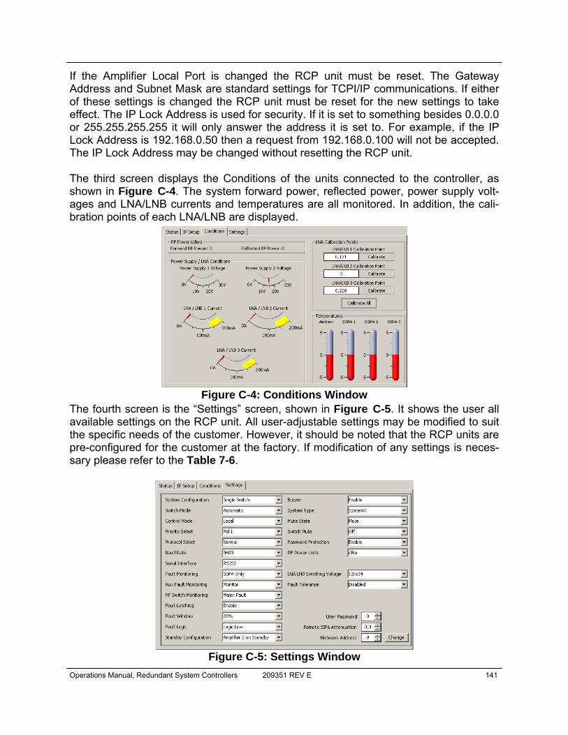
Operations Manual, Redundant System Controllers 209351 REV E 141
If the Amplifier Local Port is changed the RCP unit must be reset. The Gateway Address and Subnet Mask are standard settings for TCPI/IP communications. If either of these settings is changed the RCP unit must be reset for the new settings to take effect. The IP Lock Address is used for security. If it is set to something besides 0.0.0.0 or 255.255.255.255 it will only answer the address it is set to. For example, if the IP Lock Address is 192.168.0.50 then a request from 192.168.0.100 will not be accepted. The IP Lock Address may be changed without resetting the RCP unit. The third screen displays the Conditions of the units connected to the controller, as shown in Figure C-4. The system forward power, reflected power, power supply volt-ages and LNA/LNB currents and temperatures are all monitored. In addition, the cali-bration points of each LNA/LNB are displayed.
The fourth screen is the “Settings” screen, shown in Figure C-5. It shows the user all available settings on the RCP unit. All user-adjustable settings may be modified to suit the specific needs of the customer. However, it should be noted that the RCP units are pre-configured for the customer at the factory. If modification of any settings is neces-sary please refer to the Table 7-6.
Figure C-4: Conditions Window
Figure C-5: Settings Window

142 209351 REV E Operations Manual, Redundant System Controllers
THIS PAGE LEFT INTENTIONALLY BLANK
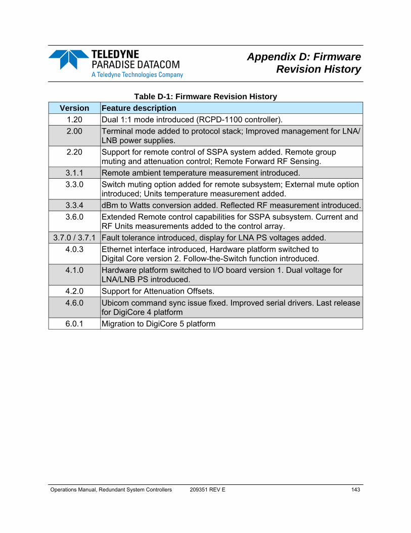
Operations Manual, Redundant System Controllers 209351 REV E 143
Table D-1: Firmware Revision History Version Feature description
1.20 Dual 1:1 mode introduced (RCPD-1100 controller). 2.00 Terminal mode added to protocol stack; Improved management for LNA/
LNB power supplies. 2.20 Support for remote control of SSPA system added. Remote group
muting and attenuation control; Remote Forward RF Sensing. 3.1.1 Remote ambient temperature measurement introduced. 3.3.0 Switch muting option added for remote subsystem; External mute option
introduced; Units temperature measurement added. 3.3.4 dBm to Watts conversion added. Reflected RF measurement introduced. 3.6.0 Extended Remote control capabilities for SSPA subsystem. Current and
RF Units measurements added to the control array. 3.7.0 / 3.7.1 Fault tolerance introduced, display for LNA PS voltages added.
4.0.3 Ethernet interface introduced, Hardware platform switched to Digital Core version 2. Follow-the-Switch function introduced.
4.1.0 Hardware platform switched to I/O board version 1. Dual voltage for LNA/LNB PS introduced.
4.2.0 Support for Attenuation Offsets. 4.6.0 Ubicom command sync issue fixed. Improved serial drivers. Last release
for DigiCore 4 platform 6.0.1 Migration to DigiCore 5 platform
Appendix D: Firmware Revision History

144 209351 REV E Operations Manual, Redundant System Controllers
THIS PAGE LEFT INTENTIONALLY BLANK

Operations Manual, Redundant System Controllers 209351 REV E 145
The following pages consist of the Redundant System Controller menu structure and specification sheet (document number 209352). Specifications shown on the following pages are subject to change. The most recent revision of the specification sheet can be viewed on the Paradise Datacom web site: http://www.paradisedata.com.
Appendix E: Documentation

146 209351 REV E Operations Manual, Redundant System Controllers
THIS PAGE LEFT INTENTIONALLY BLANK