Embed Size (px)
Citation preview
R E D U C E D SIMULATION S MODEL OF A WHEEL LOADER BY USING THE BOND GRAPH TECHNIQUE TO USE IN TRAINING SIMULATORS.
G. Romero. J. Fclcz. J. Maroto. J. D. Sanz
F T s Ingenieros Industriales. Universidad Politécnica de Madrid (UPM). C\ José Gutiérrez Abascal 2, 28006. Madrid. Spain E-mail addresscs: {gregorio.romcro.jcsus.fclcz. joaquin.maroto.juandcdios.sanzj(rt.uprn.cs.
moving machines, stcering system. l^yWORDS
md Graph. carth gecbanism.
tBSTRACT
ftiü papcr prcsents a modcl developed for simulating carth •novini; machines likc whcel loadcrs. The developed modcl is uS£(i for rea! time simulation and is ineluded in a ful I ituchincry simulator designated for thc Iraining,.
The modcl includes a mechanieal modcl of thc chassis. axlcs. suspensión systems, hydraulic actuators and mechanieal andéis of thc arnis. Al l thc models ha ve bcen simulatcd using Bund Graph elements {Karnopp ct al. 1990). Thc complete modcl has bcen developed as a modular system. using sub-mocicls of each of thc above-mentioned components. This approach hclps to minimize both thc number and complexity of the system cquations obiained fromthc ovcrall modcl.
Somc simulation examples and rcsults are also ineluded.
NTRODUCTION
Real time simulation is an indispensable requirement or models whosc purposc is to test vehiele handling. since the driver expeets to get an immediate response. as is thc case in real life. Sometimes, when a vchiclc's enginecr decides to analyze the quality or safety. or to dcsign controllcrs for ABS systems. nonnally rcly on multibody dynamic models and each question requíres a modcl of suitablc complcxity. Thc existing models span a wide range in the complcxity spectrum. For instance, thc dcsign of a controller it might be enouyh to rcprcseni the vehiele as a point mass (Liang and Peng 1999); when wc study suspensíons we can use a quancr car modcl (Ando and Suzuki 1996); a half car modcl may be preferred when analyzing ABS performance (Allcyne 1997); finally, a fuil car and higher-order multibody models may be necessary (King and Ro 2002) for more advanced studics.
A framcwork for a modular approach lo modcl i ng 3D multibody systems is availablc in thc litcraturc (Paccjka 1985. Bos 1986. Ersal 2009) but therc are not literatures about oplimizcd carthmoving machines models in thc ilems presented here.
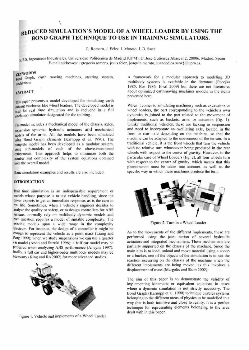
When it comes to simulating machinery such as excavators or whcel loadcrs. the part corresponding to the vehiele's own dynamics is joined to thc part relatcd to thc movement of implcmcnts. such as buckets. arms or actuators (fig. 1). Unlike traditional vchiclcs. these are lacking in suspensión and need to incorpórate an oscillating axlc. locatcd in thc front or ruar axle depending on thc machine, so that thc machine can be adapted lo thc unevenness of thc terrain. In a traditional vehiele. it is thc front whcels that turn thc vehiele with no rclativc turn whatsoever being produced in the rcar whcels with respect to thc center of gravity. However. in the particular case of Whcel Loadcrs (fig. 2). all (bur whcels turn with respect to thc center of gravity. whfch mesas ihat this phenoincnon must be takcn into account, as well as thc specifie way in which these machines produce the tum.
Figure 1. Vehiele and implcments of a Wheel Loader
Figure 2. Turn in a Whcel Loader
As to the movements of the different implcments. these are performed using thc joint action of scvcral hydraulic actuators and integralcd mechanisms. These mechanisms are partially supported on thc chassis of thc machine. Since the main aim is to load, unload and move matcriai using a scoop or a buckel. one of thc objeets of the simulation is to sce thc reaction oceurring on thc chassis of thc machine when thc different implcments are being moved, as this involves a displaccment of mass (Margoüs and Shim 2002).
Thc aim of this papcr is to demónstrale the validity of implemcnting kincmalic or equivalcnt cquations in cases wherc a dynamic simulation is not strielly necessary. The Bond Graph (Kamopp ct al. 1990) technique enables systems belonging to thc different arcas of physics lo be modclled in a way that is both intuitive and cióse to realíty. It is a perfect technique for representing elements belonging to the área dealt with in this paper.
STRUCTURE OK THE CHASSIS
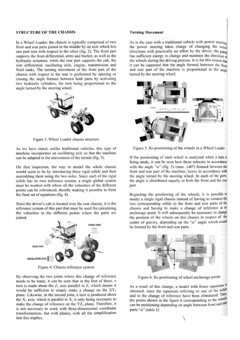
In a Wheel Loadcr, thc chassis is typically compnscd of two front and rcar parts joincd in the middlc by an axle which Icts onc part tum with rcspcct to thc othcr (fig. 2). Thc front pan supports thc front diffcrential. arms and buckct, as well as thc hvdraulic actuators, whiic thc rear part supports the cab, thc rcar diffcrential, oscülating axle. enginc, transmission and fluid tanks. The turning movement of ihc front part of thc chassis with rcspcct to thc rcar is pcrformcd by opcning or closing thc anglc formed betwecn bolh parts by activating two hvdraulic cylmdcrs, thc tum being propon ion a! to thc anglc turned by the stecring wheel.
Figure 3. Whccl Loadcr chassis structurc
As we have statcd. unlikc Iraditional vehieles. this type of machine incorporates an oscülating axle so that thc machine can be adapted to thc unevenness of thc terrain (fig. 3).
On first inspection, the way to model thc whole chassis woutd sccm tu be by introducing three rigid solids and then asscmbling thcm using the two axlcs. Since cach of thc rigid solids has its own rcfcrcncc systcm. a single global systcm musí be workcd with wherc all the vclocities of the diífcrcnt points can be rcfcrcnced. thcreby making it possible to form thc final set of cquations (fig. 4).
Sincc thc drivcr's cab is located over the rear chassis, it is thc rcfcrcncc systcm of this part that rntist be used for calculating thc vclocities in thc different points wherc thc parts are joined.
REMt PABT
OSCILLATIEKi AXLE
Figure 4. Chassis reference systcm
By observing thc two joints wherc this chango of rcfcrcnce necds to be made, it can be secn that in the first of tríese, a tum is made about thc Z, axis paral leí to Z, which means it would be suíficicnt to simply make a change on thc XY, plañe. Likcwisc. in the second joint, a tum is produced about thc X, axis, which is parallcl to X, ¡t only being necessary to make the change of rcfcrcncc on thc YZ; plañe. Thercfore. it is not necessary to work with three-dimcnsional coordínate transformations, but with planes, with all the simplification that this implics.
Turning Movement
As is the case with a Iraditional vehiele with powcr steering thc powcr stecring takes charge of changing thc wheel directions with practically no effort by thc driver. the puna has sufficicni cnergy to change and maintain thc direction of thc whecls during thc driving process. It is for this reason thai it can be supposed that thc angle formed betwecn the front and rear pan of thc machine is proportional lo the angle turned by thc steering whccl.
Figure 5. Rc-positioning of the wheels in a Whccl Loadcr
If thc positioning of cach whccl is analyzcd when a turn is being made. it can be secn how these relocate in accordanee with thc anglc "a" (fig. 5) (max. 140") formed betwecn the front and rcar part of thc machine; henee in accordanee wiih thc anglc turned by thc stecring wheel. In each of thc pnrts. thc anglc is distributed equally in both the front and the rcar part.
Rcgarding the positioning of thc wheels. it is possible to model a single rigid chassis instead of having to connect the two corresponding solids to the front and rcar parts of the chassis and having to make a change of rcfcrcncc at ils anchorage point. Ii will subsequently be necessary to change the position of the wheels on this chassis in rcspcct of the centre of gravity. depending on thc "ti" anglc which would be formed by thc front and rcar parts.
Figure 6. Rc-posilioning of wheel anchorage points
As a result of this change, a model with fcwer cquations'-obtained, since the cquations referring (o one of thc solí and to thc change of rcfcrcncc have been eliminated. Tn thc points shown in thc figure 6 corresponding to thc obcecan be positioning depending on angle betwecn front and re* parts "a" (lablc I):
WHEEL
. f 1) Right Fmnt
. (2) Left Fmnt
- (3) Rtgnt Rear
. (4) Left Rear
\x -d-ciKHp—)
+¿CM(#+—)
-4-tai{p-—i
- i / «1S( / Í -—)
Y
- ¿ • s i i H / f - ^ O
*d sm</í + y )
-dúíHp-—)
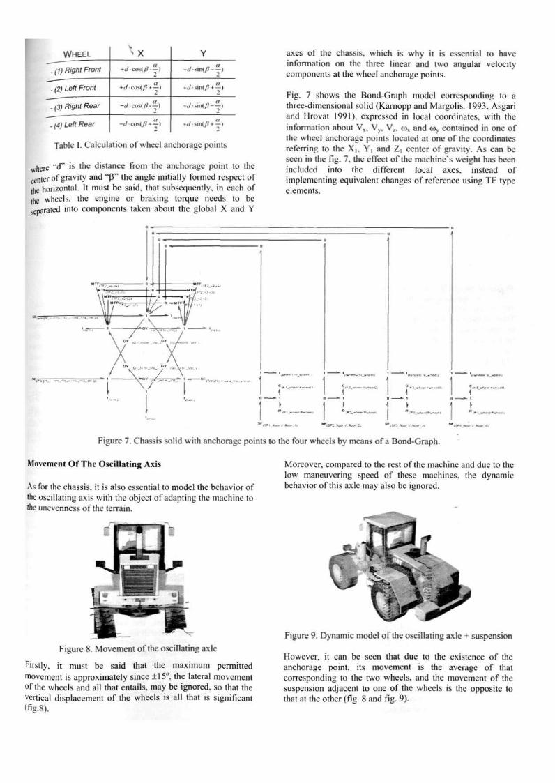
Tablc I. Calculation of whccl anchorage points
ttherc "d" i tlic distance írom thc anchoragc poini to Ihc nler ofgraviry and "fl" thc anglc initially formcd rcspcct of
ihe horizontal. Il must be said. that subsequently, in each of [[K whccls. thc enginc or braking torque nceds to be ¿eparated mío componen ts takcn about thc global X a mi Y
axes of the chassis, which is why it is csscnlial to have information on the three linear and two angular vclocity components at Ihe whccl anchoragc points.
Fig. 7 shows the Bond-Graph model coiresponding to a thrcc-dimensional solid (Kamopp and Margolis. 1993. Asgan and Hroval 1991). cxpressed in local coordinates. with thc infonnation about V„ Vy, V,, to, and to,.. containcd in onc of ihc whccl anchoragc points located at onc of thc coordinates referring to the X,. Y, and Z, center of gravity. As can be secn in the fig. 7, thc cffcct of thc machinc's wcight has becn ineluded into thc different local axes, instead of implcmenting equivalen! changos of reference using TF type elemente.
iSFí_*M> :•_*>*_:
Figure 7. Chassis solid with anchoragc points to thc four whccls by mcans of a Bond-Graph.
Movement Of The Oscillating Axis
As for thc chassis, it is also essential lo model thc behavior of thc oscillating axis with thc objccl of adapting ihc machine to the unevenness of the terrain.
Figure S. Movement of the oscillating axlc
Firstly. it must be said that the máximum permitted movement is approximately since ± 15", the lateral movement of the whccls and all that cntails, may be ¡gnored. so that the vertical displacement of the wheels is all that is signiflcant ífig.8).
Moreover, compared to the rest of thc machine and due to the low maneuvering speed of these machines, thc dynamic behavior of this axlc may also be ignored.
Figure 9. Dynamic model of thc oscillating axlc • suspensión
Howcvcr. ít can be scen that duc to the existence o I" the anchorage point, its movement is the average of that corresponding to thc two whccls, and thc movement of the suspensión adjacent to onc of the wheels is the op pos i te to that at the other (fig. 8 and fig. 9).
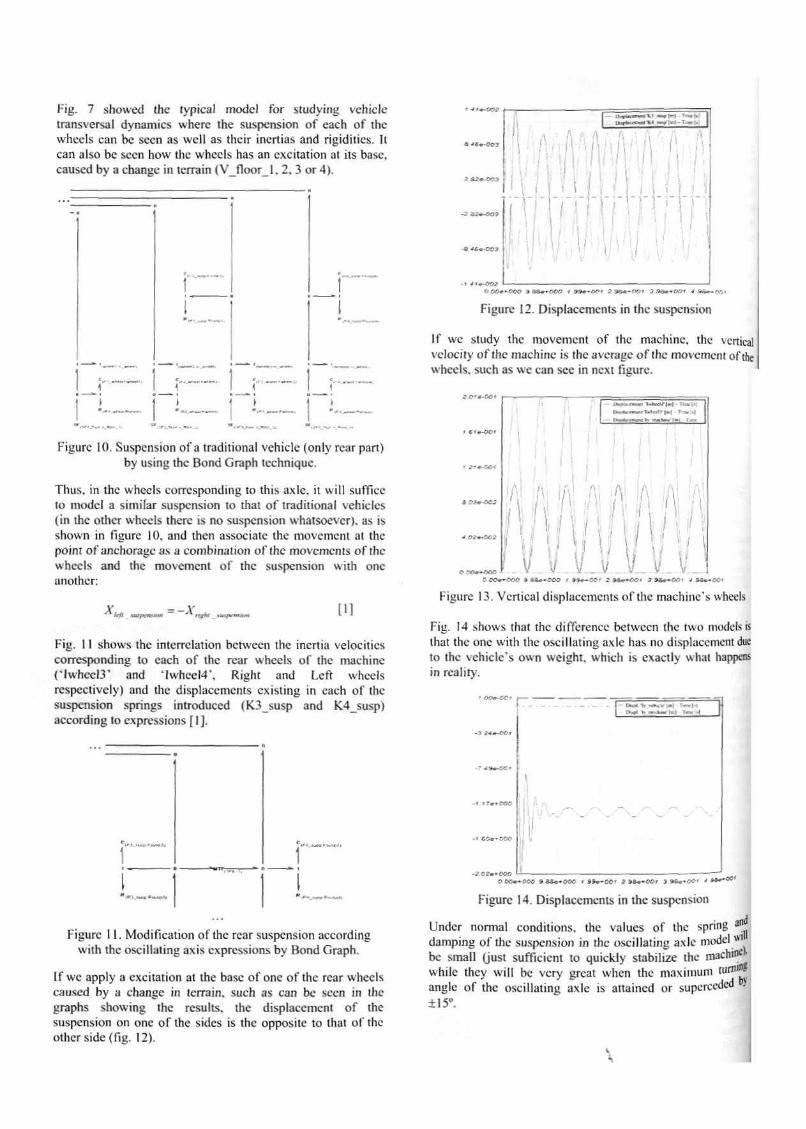
Fig. 7 showed the typical model for studying vehiclc transversal dynamtcs wherc the suspensión of caen of the whcels can be secn as wcll as thcir inertias and rigiditics. ii can also be secn how thc whcels has an cxcitation al its base, caused by achange in terrain (V_floor_1.2.3 or4).
Figure 10. Suspensión of a traditional vehicle (only rcar pan) by using thc Bond Graph tcchniquc.
Thus. in thc wheels corresponding to this axle. it will sufficc to model a similar suspensión to thai of traditional vehiclcs (in thc other wheels there is no suspensión whatsocvcr), as is shown in figure 10. and then associate the movement al thc point of anchorageas acombinalion of thc movements of thc whcels and thc movement of thc suspensión with onc another:
X = -A' [1]
I:ig. 1 l shows the interrelation betwcen the inertia velocitics corresponding lo each of thc rcar whcels of thc machine ('Iwhccl3* and Llwhcel4\ Right and Lcft whcels respcctivcly) and the displaccments existing in each of thc suspensión springs introduced (K3_susp and K4_susp) according to expressions [1].
1 • 0 1 .VW * UvU'll
Figure 11. Modificationof Ihe rcar suspensión according with the oscillating axis expressions by Bond Graph.
[f wc apply a cxcitation at ihe base of onc of thc rear wheels caused by a change in tcrrain. such as can be scen in the graphs showing thc results, the displacemeni of the suspensión on one of the sides is the opposite to Ihat of the other sidc(fig. 12).
- t 4i*-QQ2 Ü.OQ**OtíO 3 8&V-OGO 1 S9e*fl£»T Z 5 3 # ^ O í ^ J *3fr-«-ÍJf>* * 3á**-£ci
Figure 12. Displaccments in thc suspensión
lf wc study thc movement of thc machine, the vertical velocity of thc machine is the average of the movement of ihe wheels. such as wc can sec in next figure.
Figure 13. Vertical displaccments of thc machine's wheels
Fig. 14 shows that thc difference betwcen the two modeisis that thc one with thc oscillating axle has no displacemcnt due to thc vchicle's own weight, which is exactly what liappens in rcalíty.
- s-*-r.'Ci
? -O+-OC*
* ITe+OOQ
t GQw-OQO
a* . , - , . Í « I . J i ~ u 1
" -
1
_
Figure 14. Displaccments in thc suspensión
Under normal conditions. the valúes of thc spring >• damping of the suspensión in the oscillating axle model *' be small (just sufficicnt to quickly stabilize thc machinL
whilc thcy will be very grcat when thc máximum tumi -anglc of thc oscillating axle is artained or superceded . ±15".
jUCKETHANDIJNG-
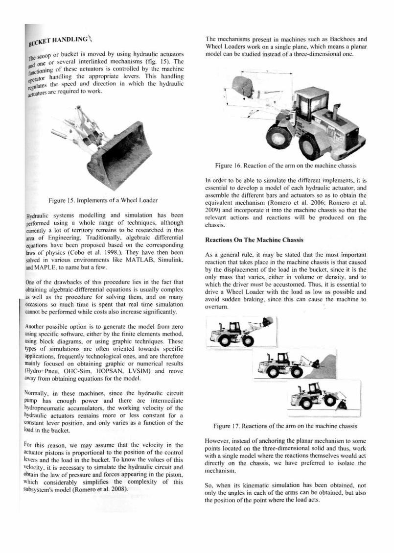
scoop or bucket is moved by using hydraulic actuaiors d onC or scvcral intcrlinked mechanisins (fig. 15). Thc
• ciioning of thcsc actuators is controlled by the machine rator handling thc approprtatc levers. This handling
Tiulatcs thc specd and dírcctíon in which thc hydraulic ^r tors are required to work.
figure 15. Impleiricnts of a Whccl Loader
Hydraulic systcms modclling and simulation has bcen performed using a wholc range of techniqucs, although currcntly a lot of territory remains to be rescarehed in this área of Kngíiiccring. Tradilionally. algebraic diffcrcntial equations ha ve been proposed based on ihc corresponding laws of physics (Cobo ct al. 1998.). They have then been solved in various environments like MATLAB, Simulink. and MAPLI'i. to ñame but a few.
One of thc drawbacks of this procedure lies in the fací that obtaining algcbraic-differential equations ¡s usually complex as wcll as the procedure for solving thcm, and on many occasions so much time is spent that real lime simulation cannot be performed while costs also mercase significantly.
Atiothcr possiblc option is to genérate thc model from zero using specifie software, cither by ihe flnitc elements method. using block diagrams, or using graphie techniqucs. Thcsc lypcs of simulations are often orienicd towards specifie applications, frequcntly tcchnological ones. and are therefore mainly focused on obtaininí; graphie or numerieal rcsults IHydro-rPneu. OHC-Sim. HOPSAN. LVS1M) and move away from obtaining equations for thc modcl.
^nrmally. in thcsc machines, since Ihe hydraulic cireuit PWnp has enough poner and thc re are intermedíate hydropncumatic accumulators. the working velocity of the hydraulic actuators remains more or less constant for a constan! lever position. and only varíes as a fu nc I ion of the load in the bucket.
For this rcason. we may assume that thc velocity in the actuator pistons is proportional to thc position of thc control levers and the load in thc bucket. To know the valúes ol'this veloeíty. ¡t is necessary to simúlate the hydraulic cireuit and obtaín the law of pressure and forces appearing in the pistón, «'hích considerably simplifies the complcxity of this subsystem's modei (Romeroet al. 2008).
Thc mechanisms present in machines such as Eíackhocs and Whccl Loaders work on a single plañe, which means a planar model can be studied tnsiead of a three-dimensional one.
In order to be ablc to simúlate the differcnt implements. it is essential to develop a modcl of each hydraulic actuator, and asscmblc the differcnt bars and actuaiors so as lo obtaín thc equivalen! mechanism (Romero el al. 2006: Romero ct al. 2009) and incorpórate it into the machine ehassis so that thc relevant actions and rcactions will be produced on the ehassis.
Reactions On The Machine Chassis
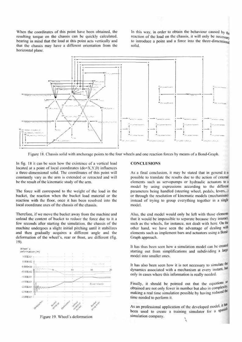
As a general rule, it may be stated that thc most important reaction that takes place in thc machine chassis is that caused by the displaccment of thc load in thc bucket since it is thc only mass that varíes, eithcr in volume or density. and to which the driver must be aecuslomcd. Thus* it is essential to drive a Whccl Loader with the load as low as possible and avoid sudden braking, since this can cause thc machine lo overturn.
i-Ai
Figure 17. Reactions of thc arm on thc machine chassis
Howcver, instead of anchoring thc planar mechanism to somc poinis located on the thrce-dimensional solid and ihus, work with a single modcl whcrc thc reaclions themscivcs would act díreetly on the chassis, wc have preferred to i so I ate the mechanism.
So. when its kincmatic simulation has bcen obtained, not only thc angics in each of the arms can be obtaincd. but also the position of thc point where thc load acts.
When the coordinates of this point have been obtained. the rcsulting torque ort the chassis can be quickly calculated. hcaring in mind that thc load al this poini acts verücally and that the chassis may have a diffcrcnt oricntation from the horizontal plañe.
In this way. in order to obtain the behaviour caused by [U rcaction of the load on thc chassis. il will only be necessary lo introduce a point and a forcé hito thc thrcc-dimensiot^i solid.
Figure 18, Chassis solid with anchoragc points to the four wheels and onc rcaction forces by meaos of a Bond-Graph.
In fíg. 18 it can be secn how thc cxistcncc of a vertical load located at a point of local coordinates (do+X.Y.O) influenecs a threc-dimensional solid, Thc coordínales of this point will constantly vary as thc arm is extended or retraeled and will be the result ofthe kinematic study of thc arm.
Thc forcé will eorrcspond to thc wcight of thc load in Ihc bucket, the rcaction when Ihe buckcl load material or thc rcaction with thc floor, once il has been resolved into thc local coordínate axes of thc chassis ofthe chassis.
CONCLLISIONS
As a final conclusión, it may be stalcd that in general it is possible to transíate thc rcsults duc to the action of cxtcrnal elements such as servopumps or hydraulic actuators lo a model by using expressions according to the diffcrcnt parameters being handlcd (stecring whccl. pedáis, levers....) or through thc rcsolution of kinematic models (mechanismsi instead of trying to group cvcrylhing logctiicr in a single modcl.
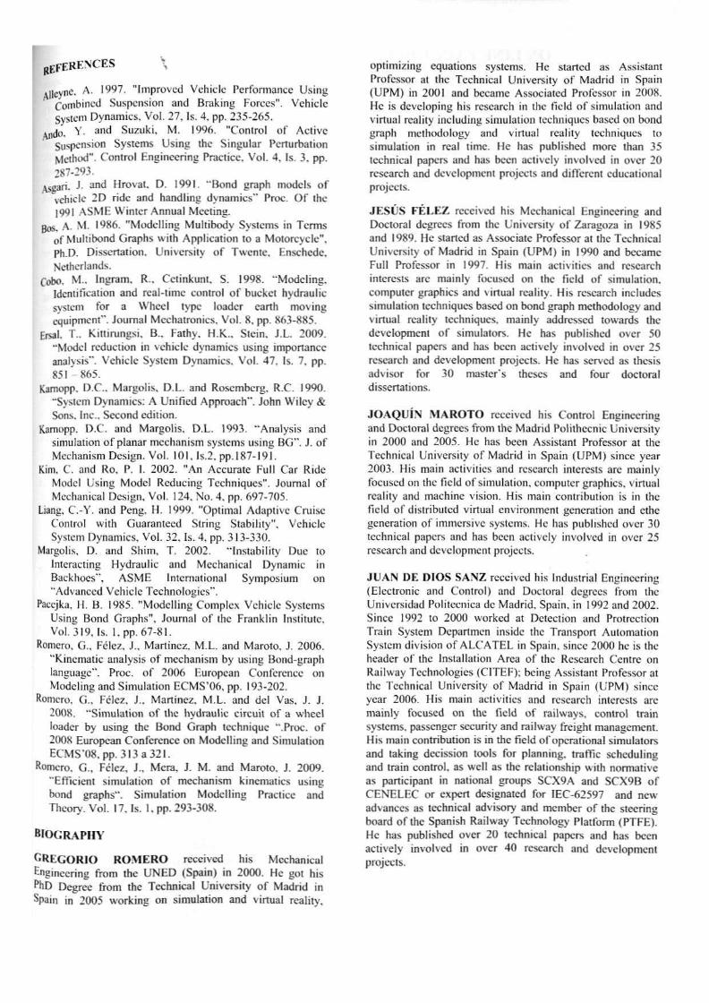
Thercfore, if wc move thc bucket away from thc machine and unload the contcnt of buckcl to reduce thc forcé due to ¡t a few scconds after starting the simulation. Ihc chassis of thc machine undergocs a slighl initial pitching until it stabílizcs and then gradually aequires a diffcrcnt anglc and thc deformation ofthe whccl's, rear or front, are diffcrcnt (fití, 19).
ceformeüon ¡mj
I.0Q&O1 -
o.«E»eo -SOOE-O;
•VOOE-OI
• I M t O l
-2.WE-G1
-I 50E-61
•J.00E-C1 •
>.
ftw=-Fmjt wtvoL*
: / /
Figure 19. Whccl's deformation
Also. thc end modcl would only be left with thosc elements that it would be impossiblc to sepárate because thcy interacL such as thc wheels, for instance, nol dealt with here. On thc other hand. wc have scen the advantage of" dealing * ¡ * elements such as implcmcnt bars and actuators using a Bond-Graph approach.
It has thus been secn how a simulation model can be crean» starting out from simplifications and subdividing a 'ar?e
model into smaller ones.
It has also been secn how it is nol necessarv to simúlate the dynamics associated with a mechanism ai every instant. w only in cases where this informalion is rcally needed
Finally, il should be pointed out that the cquations J obtained are not only fcwcr in number but also in comp'exl •* making a real time simulation possible by having reduceu time needed to perform it.
As an proiessional applieation of the dcveloped model. i' been used lo créate a training simulator for a spa11
simulation company. .
BEFERKNCES \
i l leyní. A. 1997. "Improvcd Vchiclc Performance Using Combined Suspensión and Braking Forccs". Vchiclc System Dynamics. V o l . 27, Is. 4. pp. 235-265.
indo. Y- a m i Suzuki, M. 1996. "Control o f Act ive Suspensión Systems Using thc Singular Pcrturbation Method". Control Engincering Practicc. Vo l . 4 . Is. 3. pp. 287-293.
Aseari. J- and Hrovat. D. 1991. "Bond graph modcls o f Vchiclc 2D ride and handling dynamics" Proc, O f the 1991 ASME Winicr Amiual Mccting.
Bos. A. M. 1986. "Modcl l ing Mult ibody Systems in Tcmis of Multibond Graphs with Applicat ion to a Motorcycle", Ph.D. Dissertation. Univcrsity o f Twente, Enschede. Nctherlands.
Cobo. M., Ingram. R., Cctinkunt. S. 1998. "Modc l ing . Identification and real-time control o f bucket hydraulic sysiem for a VVhccl type loader carth moving equipment". Journal Mechatronics, Vo l . 8, pp. 863-885.
Ersal, T.. K.itlirungsi, B., Fathy. H.K.. Slein. J.L. 2009. "Model reduction in vchiclc dynamics using importance analysis". Vchiclc System Dynamics. Vo l . 47. Is. 7. pp. 8 5 1 - 8 6 5 .
Kamopp, D.C.. Margolis, D.L. and Roscmberg. R.C. 1990. "'System Dynamics: A Uni f icd Approach". John Wi lcy & Sons. Inc.. Second edi l ion.
Kamopp. D.C. and Margolis. D.L. 1993. "Analysis and simulation o f planar mechanism sysiems using BG" . J. o f Mechanism Dcsign. Vo l . 101, ls.2. pp. 187-191.
Kim. C. and Ro. P. I. 2002. "An Accurate Full Car Ride Model Using Model Reducing Tcehniques", Journal o f Mechanical Dcsign, Vo l . 124. No. 4 , pp. 697-705.
Liang, C.-Y. and Pcng. H. 1999. "Optimal Adaptive Cruise Control wi th üuaranteed String Stabil i ty", Vehiclc System Dynamics. Vo l . 32. Is. 4. pp, 313-330.
Margolis. D. and Shim. T. 2002. "Instabi l i ty Due to Intcracting Hydraulic and Mechanical Dynamic in Backhocs". A S M E International Symposium on "Advanced Vehicle Technologies".
Paccjka. I I , B, 1985. "Modcl l ing Complcx Vchiclc Systems Using Bond Graphs". Journal o f thc Franklm Institutc. Vol. 319, Is. l . pp . 67-81.
Romero, G.. Félez, J „ Martínez. M.L. and Maroto. J. 2006. "Kinematic analysis o f mechanism by using Bond-graph language". Proc. o f 2006 Europcan Conferencc on Modcling and Simulation ECMS'06. pp, 193-202.
Romero. G.. Félcz, J.. Martínez. M.L. and del Vas, J. J. 2008. "Simulat ion o f thc hydraulic circuit o f a whcel loader by using thc Bond Graph tcchniquc ".Proc. o f 2008 European Conference on Modcl l ing and Simulation E C M S , 0 8 . p p . 3 l 3 a 3 2 í .
Romero. C , Fclcz, J.. Mera, J. M. and Maroto. J. 2009. "Efficient simulation o f mechanism kinematics using bond graphs". Simulation Modcl l ing Practicc and Thcory. Vo l . 17. Is. 1. pp. 293-308.
B l O G R A P H Y
G R E G O R I O R O M E R O reccived his Mechanical ^ngineering from thc U N E D (Spain) in 2000. He got his PhD Degree from thc Tcchnical Univcrsity o f Madrid in Spain in 2005 work ing on simulation and virtual reality.
optimizing equalions systems. He started as Assislant Profcssor al the Technical Universily o f Madrid in Spain (UPM) in 2001 and became Associated Profcssor in 2008. He is dcvcloping his rescarch in thc field o f simulation and virtual reality including simulation tcehniques based on bond graph mcthodology and virtual rcali ly lechniques to simulation in real time. He has published more than 35 tcchnical papers and has been activcly ¡nvolved in over 20 rescarch and dcvclopmcnt projeets and different educational projeets.
JESÚS F É L E Z received his Mechanical Engíneering and Doctoral degrecs from thc Universily o f Zaragoza in 1985 and 1989. He started as Assoeiale Profcssor at thc Technical Univcrsity o f Madrid in Spain (UPM) in 1990 and became Full Profcssor in 1997. His main activities and rescarch interests are mainly focused on thc field o f simulation. Computer graph ¡es and virtual reality. His rescarch inc ludes simulalion tcehniques based on bond graph mcthodology and virtual reality tcehniques. mainly addrcssed tovvards thc dcvelopmcnt o f simulators. He has published over 50 tcchnical papers and has been activcly ¡nvolved in over 25 rescarch and dcvelopmcnt projeets. He has served as thesis advisor for 30 master's theses and four doctora! dissertations.
J O A Q U Í N M A R O T O reccived his Control Engincering and Doctoral degrecs f rom thc Madrid Polithccnic University in 2000 and 2005. He has been Assistant Profcssor at the Technical Univcrsity o f Madrid in Spain (UPM) since year 2003. His main activities and rescarch interests are mainly focused on thc f ield o f simulation, computer graphics. virtual reality and machine visión. His main eontribution is in thc field o f dislributcd virtual environment gcneration and ethe gcneration o f immcrsivc systems. He has published over 30 tcchnical papers and has been activcly involved in over 25 rescarch and dcvelopmcnt projeets.
J U A N DE D IOS S A N Z reccived his Industrial Engincering (Electronic and Control) and Doctoral degrees f rom the Universidad Politécnica de Madr id, Spain. in 1992 and 2002. Since 1992 to 2000 workcd at Detection and Protrcction Train System Departmen inside thc Transpon Aulomal ion System división o f A L C A T E L in Spain. since 2000 he is thc header o f thc Installation Área o f thc Rescarch Centre on RaÜway Technologies (CITEF); being Assistant Profcssor at thc Tcchnical University o f Madrid in Spain (UPM) since year 2006. His main activities and rescarch interests are mainly focused on the field o f railways. control train systems. passenger security and railway freighi management. His main eontribution is in thc field ofopcrat ional simulators and taking decission tools for planning. trafile scheduling and train control, as wcl l as the rclationship with normative as participant in national groups SCX9A and SCX9B o f CENELRC or expert designated for 1EC-62597 and ncw advanecs as tcchnical advisory and member o f thc steering board o f thc Spanish Railway Technology Platform (PTFE). He has published over 20 technical papers and has been activcly involved in over 40 rescarch and dcvclopmenl projeets.


