Embed Size (px)
Citation preview

Rednet: A Wireless ATM Local Area Network using Infrared Links
J. H. Cordon. T. S. Duf/; M. F. Jukl, C, R. Kcdmunek.
B. N. Locanthi, J. P. Suvicki, J. H. Venutolo
AT&T BelI Laboratories Murray Hill NJ 07974
Abstmct - Rednet provides portable computers with an incxpensivc wireless network connection. It is designed to support seamless end-to-end communication using the Asynchronous Transfer Mode (ATM). Rednet uses a Iow- power infrared transceiver operating at 2-5 Mbps over a distance of 4 meters. The link layer protocol supports link sharing and transport of ATM cells over the link. Ceiling mounted base stalions in each room act as gateways between the infrared link and rhe wired network. Rednet is designed to support user mobility, so that users can roam from room to room and access network services in a loca- tion independent manner. The paper describes our infrared physical layer and link layer protocols, presents an ovcr- view of protocols for dynamic address assignment and con- ncction management, and summarizes the status of the work.
1. Introduction Interest in wireless communications is growing, both as a research topic and as a commercial opportunity. Personal communications networks (PCN) have the potential to pro- vide a ubiquitous communications environment for a soci- ety of increasingly mobile users. In addition, there is grow- ing interest in wireless in-building LANs because of the convenience of wire elimination and mobility. Low perfor- mance infrared links are becoming popular as an inexpen- sive way for laptop computers and PDAs to exchange information with other devices over short distances. Although the PCN work has focused on voice communica- tion. a trend is to support multimedia communication on portable devices in a location independent manner. This will require increased wireless link bandwidths and the integration of wireless LANs wich high-speed local area networks.
This paper describes the architecture and status of Rednet, a wireless local area network that WC are building. Rednct is based on a low-cost, low-power infrared tran- sceiver which support% 2-5 Mbps over 4 meters. The link layer protocol supports link sharing among up to 32 wire- less nodes and provides for the transport of Asynchronous
Permission to make digital/hard copies of all or part of this material for personal or classroom use is granted without fee provided that the copies are not made or distributed for profit or commercial advantage. the copy-
Transfer Mode (ATM) cells over lhe link. It is advanta- geous to use small cells on low speed links to reduce the link scheduling latency. In addition, our medium access protocol allows us to bound the link access delay for delay-sensitive, continuous-media traffic.
Rednet aims to support infrared communication from a wide range of fixed or portable nodes. Nodes might range Tom tetherless computer peripherals such as key- boards to handheld multimedia terminals. The goal is to support end-to-end communication using ATM. ATM gen- crally allows users to be given end-to-end performance guamntecs, but the higher cell loss rates possible in wire- less networks are a new problem, potentially affecting both link layer and end-to-end protocols.
A Rednet local area network is constructed by instaIling a ceiling mounted infrared base station in each room. Base stations are connected into the wired ATM net- work via either point-to-point or multi-drop wiring. Since infrared links have limited range, a single base station pro- vides coverage for a smalI office, while larger offices may require multiple base stations.
Rednet is being designed to support user mobility, so that users can roam from room to room and access network services in a location independent manner. To support roaming, mobile nodes and base stations participate in a connection re-establishment protocol. For location regis- tration, we draw on previous work from the European GSM system [RAH93]. Some buildings will not bc wired to pro- vide ubiquitous service, and our infrared links do not sup- port soft handoff, so applications must be tolerant of tem- porary disconnection.
The outline of the paper is as follows. Section 2 describes the infrared physical layer and Section 3 describes the link layer protocol. Sections 4 presents a ref- erencc architecture as background for the dynamic address ,assignmcnt and connection management protocols described in Section 5. Finally, Section 6 describes the implementation status and Section 7 presents our conclu- sions and plans for future work.
2. Infrared Physical Layer Infrared signaling is an interesting altcmative to radio fre- quency transmission for a wireless LAN. Cost, perfor- mance, range, power consumption and bit error rale arc
right notice, the title of the publication and its date appear, and notice is given that copyright is by permission of the ACM, Inc. To copy otherwise.
important and inter-related issues. In this section, we will
to republish, to post on servers or to redistribute to lists, requires specific permission and/or fee.
For further information, contact [email protected].
MOBICOM 95 Berkeley CA USA 0 1995 ACM 0-89791-814-2/95/10..%3.50
151

touch on these issues while summarizing our infmred link design.
Since we intend to operate in a LAN environment sup- porting portable computers, Rednet uses a non-directed link which does not require precise alignment between a trans- mitter and a receiver. There are two types of non-directed links: those which require line of sight between a transmit- ter and receiver, and those in which the receiver can recover a signal from diffuse rellections from the walls or ceiling. While a diffuse system is mosl desirable from a user’s point of view, the extreme signal attenuation’creates a serious design problem, particularly when trying to achieve holh high speed and low power. The Rednet design rcqu:lres line of sight under typical operating condi- tions. Rednet transmitters employ a broad beam diffuser and receivers use a non-imaging hemispherical concentra- tor [SAV94.1 with a wide capture cone (approximately 75 degree half-angle). With ceiling mounted base stations, the transceiver associated with a portable computer needs to be pointed towards the ceiling.
An important motivation for our use of infrared is that infrared syslems can be quite inexpensive and use relatively low power while achieving the megabit per second speeds needed for multimedia communications. Our present tran- sceiver achieves a data rate of 2 Mbps with a parts cost of a few dollars. The primary disadvantage of infrared systems is that low-.power non-directed links have quite limited range. Our transceiver has a range of 4 meters with 70 mW of peak opt&d power at the transmitter. As a resull the coverage area of a base station must be small, about the size of a one-person office. The limited range, combined with the fact that infrared radiation does not pass through walls or around comers, does have the advantage that adja- cent rooms can use independent intiared links without interfering with each other. This allows the full bandwidth of an infrared link to be dedicated to a small number of users.
A goal for the transceiver design was to keep the mod- ulation and detection circuitry as simple as possible without compromising bit error rate (BER). Panter [PAN651 evalu- ated modulation techniques, but looked only at RF systems. Panter also attempted to minimize the peak transmitted power to noi.se for a given BER, while in practice the aver- age transmitted power retlects more accurately on battery life. Panter also did not evaluate baseband on-off keying, which is an option in optical systems. Our analysis of avcr- age power to noise shows that on-off keying is nearly as good (within 1 db) as phase-shift-keying and amplitude- shift-keying, which have the best performance. On-off keying is a few tenths of a db better than frequency-shift- keying.
Detection of the baseband signal from low frequency optical noise is accomplished through edge detection. As a result, no up conversion and down conversion of the digital signal is needed, allowing a particularly simple transmitter and receiver. In addition, the full bandwidth of the LEDs is used for digital information with baseband on-off keying. Since the bandwidth of inexpensive LEDs is the limiting factor on the bit rate that can be achieved in an infrared sys- tem, baseband on-off keying achieves higher bit rates than tither frequency or phase-shift keying. Pulse position mod- ulation schemes, which use the position of a narrow pulse to convey multiple bits, also use a larger LED bandwidth for a given bit late than on-off keying.
Most of IJK power in an infrared system is consumed
by the infrared source. Light. emitting diodes are relatively inefticient when compared with high-quality lasers, but they appear to be the only option when cost is taken into account. Our current Rednet transmitter consist< of three 950 nm LEDs connected in series across the 5 V supply voltage. When active, the transmitter uses 500 mW of elec- trical power while the quiescent power consumption at the receiver is only 35 mW. Since a node’s transmitter is active only when sending, the impact on battery life is small. It is possible to increase the link range by increasing the transmitter power, but the received optical power varies as l/r* so there are diminishing returns. We believe that our present design has made a reasonable tradeoff between range and power for an in-building LAN.
The design of an infrared receiver for a wireless LAN presents a number of challenges. For example, the photodi- ode current at the receiver due to ambient lighting is orders of magnitude larger than the signal current, even when using an absorptive fiiter at the receiver. In addition, fluo- rescent lights produce a large low frequency component which must be filtered out. In addition, since we intend to multiplex the infrared link on a cell by cell basis, each cell may arrive at the base station with a very different power level. A typical solution is to use automatic gain control, but the long time constants in such de-signs prevent their use here. As mentioned above, the solution to both of these problems in .Rednet is for the receiver to use edge- detection. The edge-detection circuit has a fairly narrow pass band, which filters out the low frequency noise. The Rednet receiver has a sensitivity of 35 nano-Amperes of photocurrent. The dynamic range of 43 db corresponds to the optical energy captured by the 1” diameter lens at 4 meters compared with the energy captured with the trans- mitter and receiver in direct contact.
The USC of edge detection at the receiver has some subtle implications on the design of the medium access pro- tocol, which we will discuss in the next section. Another issue is that the large photodiode array, as well as the high- impedance Front-end of the receiver i&elf, ‘are very suscep- tible to input electrical noise. To cope with this problem, the receiver is packaged in a metal can which provides shielding from noise. The photodiodes themselves are mounted on the top of the can and the hemispherical con- centrator is covered with a fme mesh shield that is electri- cally connected to the can.
3. Infrared Link Layer Protocol The Rednet link layer protocol provides synchronization, framing, and collision-free medium access for the infrared link between one or more wireless nodes and an infrared base station. The medium access portion of the protocol was adapted for the wireless environment from a well- known contention protocol that was used in Datakit [FRA83] and lncon [FRA93], which we will refer to as binary countdown here. Binary (or M-ary) countdown has also been proposed for use in the radio frequency cellular environment under the name of RAMA [AMI93]. The four main attributes of binary countdown from our point of view are simplicity, efficiency, fairness, and low latency. Sim- plicity is important to cost and design eflort. Efficiency conserves precious bandwidth. Fairness is important when multiple nodes share the link and low latency is important for multimedia traftic. We will return to these issues afbsr we present the protocol.
Medium access protocols designed for the wired envi- ronment must typically be adapted to work in the wirele,ss
152

environment because of the “hidden node” problem. Two nodes cannot necessarily hear each other’s transmitted sig- nal, either because they are out of range or because of mul- tipath fading in an RF system. While these nodes may be able to communicate with a third.node, say one which is equidistant. between them, distributed medium access schemes such as CSMAKD require the nodes to hear each other to resolve contention for the medium. In Rcdnct, we define the coverage ureu of a base station as the region in which a mobile node receives a good quality signal from the base station. We have the base station echo received signals during the medium access portion of the protocol, so that every node resolves contention using the same information.
3.1. Timing Wecovery, Synchronization and Framing All link layer protocols require the receiver to acquire bit and cell (or packet) synchronization. We use a slotted pro- tocol in Rcdnct where each slot corresponds to the time to transmit an ATM cell. A cell slot consists of three phases: the Preamble! Contention, and Data phases. Each base sta- tion is responsible for generating time slots by sending a preamble over the infrared link at regular intervals. Nodes use the preamble to synchronize with the base station. Fol- lowing the preamble, nodes contend with each other for access to the link using binary countdown, which dctermin- istically guarantees access to a particular node, possibly the base station. The winning node then transmits an ATM cell during the Data phase. The preamble is chosen to be a pat- tern which cannot occur in the Contention or Data phases. With this overview, we now review our approach in more detail.
Timing recovery in digital transmission systems is often accomplished by using a tank circuit or phase locked loop. However, at the bit rates of interest to us, a simple and inexpensive approach suffices. Each node has a free running oscillator at eight limes the nominal bit rate. Tim- ing recovery is done using a scheme similar to a UART. Each receiver oversamples the incoming stream and adjusts the phase at lhc beginning of each transmission. The tim- ing accuracy of incxpcnsive oscillators is sufficient for the receiver to stay synchronized for the duration of a cell.
A number of schemes could be used for framing, for example, using a block code such as 4Bl5B or by using HDLC flags with bit stufting. A third possibility would be to use “flywheel” framing as in Tl transmission, in which a receiver locks after observing a pre-determined sequence of framing bits for some number of frames. We have chosen an alternative scheme that is simple to implement in field programmable gate arrays (FPGAs), but which is quite robust. Each byte in the Data phase is transmitted with odd parity and the preamble consists of two identical bytes (c.g. 10101010) with even parity. At the end of a cell slot, there is a guard period with no transmission and a receiver begins to search for the preamble. Once a valid preamble is detected, the receiver is in frame. Since a valid preamble cannot occur in data, a receiver cannot be confused by a valid reception. Moreover, since the cell slots are of fixed duration, the protocol can be made more robust by requir- ing more than one preamble before a receiver declares itself to be in frame, much as in the flywheel approach. Note that the byte parity could also be used for error checking, but its true purpose is framing.
3.2. Medium Access Medium access in Rcdnet is achieved through a contention protocol, binary countdown, that provides bounded latency and collision fret, deterministic access to the infrared link. Each node, including the base station, is assigned ;I con- tention undress that is unique among the nodes sharing the link. Since there are only a small number of nodes sharing a link, WC need only a few bits for the contention address. WC will describe how contention addresses are assigned later; for the moment, it suffices to think of a contention address as permanently assigned to a node. The binary countdown protocol works as follows. During contention, nodes that have a cell to transmit send each bit of their con- tention address in bit serial order most significant bit fist. Because of the hidden node problem, the base station echoes each bit during contention so that all nodes in its coverage area resolve the distributed contention problem with the same information. For the moment, we can think of the base stalion sending a signal that is a “wired OR” of the received signals. During each bit interval, each node compares its received signal with what it transmitted. II they match, a node continues to the next bit; otherwise, the node drops out of contention until the next cell slot. This protocol has the effect of “counting down” from the highest address to the lowest, eliminating all but the highest con-
tending address. The protocol guarantees that a single node wins contention so there arc no wasted cell slots on the link. The winning node sends its cell during the Data phase and contention occurs again during the next cell slot.
As described, this protocol is collision free, but unfair since the node with the highest address always wins. We modify the protocol by using a “group priority” bit as the most significant bit of the contention address. Initially, all of the nodes arc at low priority so the group bit is zero. After a round of contention won by a node when the group priority bit is zero, those nodes that have lost contention enter a high priority group and arc allowed to set their group bit. During subsequent contention cycles, each node in the high priority group will win conlention in turn until all nodes arc at low priority again. With this modification, the contention protocol behaves like round robin, giving equal access to all nodes that have something to send.
We’ve glossed over a few details that we will clear up now. Since we are sending on-off keyed optical signals, if more than one station sends a “one” bit it is intuitive to think of the signals being ORed at the base station to result in a “one” bit at each receiver, similar to wired OR. How- ever, the use of edge-detection produces a non-intuitive result, namely that a trunsition in the optical signal level takes precedence. For example, if one node sends ’ 1 I ’ and another node sends ‘lo’, ‘10’ will be detected by the base station’s receiver. This has the effect of shuffling the prior- ity of contention addresses, but does not otherwise affect the behavior of the protocol.
Secondly, contention hits must be slightly longer in duration than ordinary data bits due to propagation delay and the delay through the band-limiting filters in the optical receivers. In our current prototype, contention bits are three bits long and we use six contention bits including the group priority bit, so the Contention phase lasts 18 bit times.
While the description above explains the medium access protocol, we did not explain how a node determines whether to receive a cell. Of course, if a base station loses contention, it receives the cell contained in the Data phase
153
of the cell slot. Since the protocol as described does not support peer to peer communication, all communication flows through the base station. If a node loses contention, there is a chance that it lost to the base station and that the cell being ,transmitted is intended for it. We have therefore adopted the convention that nodes filter incoming cells based on the virtual path bits of the ATM cell header. If the VP1 bfts match a node’s contention address, it receives the cell; olherwise, it discards it.
A number of variants on the basic protocol are possi- ble. For example, we can give the base station a larger share of the link bandwidth by adding an additional priority bit or by allowing the base station to violate the group pri- ority rule in a controlled way. An improvement on the nroup priority protocol is described in [VER88]. These Variations all retain the essential characteristics of the pro- tocol: namely, f&air, deterministic access and bounded latency.
3.3. Color There is one additional detail needed in order to support mobile nodes. When a node enters the coverage area of a new base station, its contention address is no longer valid and the virtual circuit identifiers for each of its connections may need to be remapped. In order not to conflict with other nodes that are in the new coverage area, a node must quickly discover that it has moved and immediately sup- press transmission, at least until it has a new contention address. A common approach is to have each base station send a globally unique identifier (e.g., its IP address [IONYl]) periodically. This approach is well suited to packet networks, where the numbers of bits in the global identifier is a small fraction of the bits transmitted. In a cell network, however, having the base station send a glob- ally unique identifier with every celI is inefficient. In Red- net, each base station is assigned a “color” such that adja- cent or nearby base stations do not have the same color. The term c,olor is a reference to graph coloring, and only a few bits are: needed.
Before transmitting a cell, a node reads the most recently received color value from a register in the medium access control (MAC) device. If the color has changed, the node suppresses transmission and requests a new con- tention address from the base station using a dynamic address assignment protocol that we describe later. If a node is not transmitting, it reads the color register periodi- cally, based on a timer. Since only a small number of col- ors are actually needed, we could encode color in the preamble, giving a colored preamble. In order to simplify the design effort, our implementation adds an eight bit color field plus a parity bit following the Preamble phase.
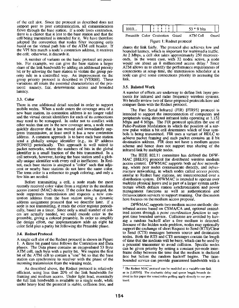
3.4. Rednet Protocol A single cell slot of the Rednet protocol is shown in Figure 1. A three bit guard time follows the Contention and Data phases. The Data phase contains an encapsulated 53 Byte ATM cell, leach byte with a parity bit, We require the first bit of the ATM cell to contain a “one” bit so that the base station can synchronize its receiver with the phase of the incoming transmission from the winning node.
As daicribed above, the Rednet protocol is relatively efficient, using less than 20% of the link bandwidth for framing and medium access. Under light load, essentialljl the full link bandwidth is available to a single node, while under heavy load the protocol is stable, collision free, and
53 * 9 bits II Praunble Color Contention Guard ATM Cell GtEUd
Figure 1: Rednet protocol shares the link fairly. The protocol also achieves low and bounded latency, which is important for multimedia traffic. At 2 Mbps, tt cell slot takes approximately 250 microscc- onds. In the worst case, with 32 nodes active, a node would see about an 8 millisecond access delay.’ Since ATM allows us to identify the performance requirements of connections at setup time, the transmission scheduler at a node can give some connections priority in accessing the link.
3.5. Related Work A number of efforts are underway to define link layer pro- tocols for infrared and radio frequency wireless systems. We briefly review two of these proposed protocols here and compare them with the Rednet protocol.
The Fast Serial Infrared (FIR) [FIR951 protocol is intended to support the interconnection of computers and peripherals using directed infrared links operating at 1.152 Mbps and 4 Mbps. The FIR protocol specifies the use of Pulse-Position Modulation in which the position of a nar- row pulse within a bit cell determines which of four svm- bols is being transmitted. FIR uses a variant of HDL6 to achieve packet framing and each packet contains an 8 bit destination address. FIR does not have a medium access scheme and hence does not support true sharing of the infrared link by multiple nodes.
The IEEE 802.11 committee has dctined the DFW- MAC [BEL93] protocol for distributed wireless medium access control. DFWMAC supports both ad hoc network- ing, where peer nodes communicate directly, and i@us- tructure networking, in which nodes called access points, similar to Rednet base stations, are interconnected over a distribution system. DFWMAC is intended to operate over multiple physical layers and is part of a larger system archi- tecture which defines station synchronization and power management functions as well as authentication and (re)association services to support roaming. Our discussion here focuses on the medium access proposal.
DaAC supports two medium access methods: dis- tributed access based on CSMAKA and, optional cenbral- ized access through a point coordination function to sup port time bounded service. Collisions are avoided by hav- ing a random backoff after a free medium is detected. Because of the hidden node problem, nodes may optionally support the exchange of short Request to Send (RTS)/Clear to Send (CTS) messages between source and destination nodes. Both the RTS and CTS messages contain the length of time that the medium will be busy, which can be used by a potential transmitter to avoid collision. Specific nodes can be given priority by setting a constant per-node inter- frame delay between the time that the medium is declared free but before the random backoff begins. The time- bounded service can provide guaranteed bandwidth with a
’ The Rednet MAC protocol can be modeled a~ a variable-rate link a in [LEE95]. The stochastic delay and queue length bounds de- rived in this paper for round robin polling apply directly to our pro- toco1.
154

long delay but small delay variance by having nodes reserve frames within a super-frame structure.
DFWMAC is similar to Rednet in that it supports both asynchronous data and an (optional) time bounded service. In Rcdnet, however, the time bounded service comes essen- tially for free, whereas in DFWMAC both RTS/CTS and the time bounded service are protocol options that were grafted onto the CSMAKA scheme and which may not be supported by every node. DFWMAC was designed to sup- port packet access and hence it is not surprising that it appears to be a poor choice for cell access, which was our primary objective. DFWMAC has the advantage of being designed for both ad hoc and infrastructure networking. A variant of the Rednet protocol could be designed to support ad hoc networking, basically by having a node assume the role of the base station. We have not explored the use of binary countdown in radio frequency systems, although other authors are exploring this issue [AM193]. On balance, DFWMAC is substantially more complex than the Rednct protocol, without providing much additional functionality.
A commercial infrared LAN, made by Photonics, uses the 802.11 protocol. It operates at 1 Mbps with a range of 5 meters. WC do not know what modulation technique is used in the Photonics system, but the physical layer param- eters are similar to those of Rednet.
4. Reference Architecture This section describes a reference architecture for the ATM wired infrastructure for a network of base stations. The section provides background for the dynamic address assignment and connection management protocols dis- cussed in Section 5. We are currently building an initial testbed network of base stations to provide wireless service to mobile laptop computers and handheld multimedia ter- minals. This testbed network is described in Section 6.
to
uu mobile nodes
Figure 2: Reference Architecture
The reference architecture is shown in Figure 2. A ceiling mounted base station supports one or more wireless nodes within its coverage area. The small coverage area of a base station is well matched to the work space on a desk of a single person, and a base station could be positioned accordingly. Since base stations all share the same optical wavelength and are unsynchronized, their coverage areas are typically designed to be non-overlapping and there will be dead zones. In practice, the dead zones occur in unus- able space such as doorways, although in large rooms there may be some need for users to adjust their positions to fall within a base station’s coverage area.
Each base station is connected by point-to-point wir- ing to a local area ATM switch. A base station forwards cells between the wired and wireless links. If link error rates are sufticicntly high, performance can be improved by a link layer retransmission protocol [DES93]. In this case, the base station would terminate this retransmission proto- col.
Logically, a mobile host views its infrared link as a point-to-point connection to an ATM LAN. It uses a dedi- catcd signaling connection to csmblish, maintain, or clear connections. To the network, however, the infrared link is a multidrop LAN where mobile nodes come and go and where each mobile node has its own signaling comrcclion. When a mobile host boots or moves into a coverage area, it needs to be assigned a contention address before it can transmit. The address assignment and connection manage- ment can be handled in one of two ways. One approach is to add support for these functions to the connection man- ager (CM) controlling the ATM LAN. The second approach is to perform these functions in the base station. In the latter approach, the base station acts as a small ATM switch terminating multiple signaling connections. In par- ticular, a base station has a signaling virtual circuit to each active mobile node in its coverage arca and a signaling vir- tual circuit to the CM in the ATM switch, shown in Figure 2. For specificity, we assume the latter approach in the ref- erence architecture.
A location server (LS) is also shown in Figure 2. An LS is associated with an administrative domain that may consist of a number of ATM switches. The LS maintains the current location for every mobile node within its admin- istrative domain. The LS also tracks the location of nodes that are registered with it% domain, but which are roaming outside of it. As shown in the tigure, we assume that domains are interconnected by a wide-area ATM network.
5. Higher Layer Protocols In this section, we describe our present view of the proto- cols for dynamic assignment of contention addresses, loca- tion and connection management.
5.1. Dynamic Address Assignment When a mobile host boots or moves into a new coverage area, it needs to be assigned a contention address before it can transmit. This is accomplished using an address assignment protocol in which the mobile contends with a well-known contention address to request a new contention address from the base station. In addition, the mobile needs a signaling connection to the base station to establish, clear, or re-establish connections. The mobile also needs to be *signed a network-layer routing address to which incom- ing connections are routed. We combine all of these func- tions into a simple protocol.
By convention we reserve a contention address of all ones* for address assignment. When a mobile moves into a coverage area, it suppresses transmission of any queued cells and loads the well-known address of all ones into the MAC device. The node (or nodes) then contend with this address and send an address request cell to the base station containing the globally unique identifier (guid) of the node. Each node uses a random backoff timer as in slotted ALOHA in case it does not receive a response within a
’ and a virtual circuit identifier of all zeros
155

timeout interval. Address requests are rare so collisions are expected to be infrequent. When the base station receives a request, it broadcasts a response by setting the VP1 bits to all ones so that any node with a contention address of all ones will receive the cell. The response contains the guid of the requesting node, the guid of the responding node, a contention (MAC) address, the virtual circuit to be used for signaling, and the routing address of the mobile node. The node loads the new contention address into its MAC device. Since re-establishment requires VCs to be remapped, cell transmission is re-enabled for the signaling comlection ‘and the connection rc-establishment protocol is initiated.
Since comention addresses are a finite resource, unused addresses must be reclaimed by the base station. One approach is to have a mobile node free its contention address over the wired network when it moves into a new coverage area. This is not robust, however, since a mobile node may fail or be powered down. Therefore, mobile nodes send a address request periodically as a ‘keepalive’ exchange and base stations time out unused contention addresses after a suitable amount of time has elapsed.
5.2. Location Management Our goal is to support user access to network services in a location independent manner. Our approach to mobility in ATM networks draws on work from circuit-switched cellu- lar telephony, specifically the GSM system [RAH93]. The network maintains location information about mobile nodes in location servers in order to route connections. In our net- work, we expect mobility to be iufrequent, so it is reason- able to have users register their location as they roam. It is also possible to decrease me overhead due to location updates by using paging [BAR94, CHIYll.
Every mobile node has a home location, which is the administrative domain where it is registered on a long-term basis. If a :node is roaming, the location server in its home domain record:; the domain that it is currently visiting. For consistency with GSM, we call this location server the home location register (HLR) when appropriate. The node’s dialing address, used to establish a connection to the node, u:niquely identities the HLR. Each node also has a routing address, representing its current location, used for routiI~g.
Figure 3 illustrates the locatiou registration procedure. A mobile node registers its location when it enters a new administrative domain, or when it crosses the boundary between two base station’s coverage areas. In step 1, the node registers its new routing address with the local loca- tion server. In GSM, this is the visitor location register (VLR). If this is the first time that the VLR has encountered the node, it updates the node’s HLR so that incoming calls to the mobile node can be routed to the visited domain. The HLR returns user profile information and an authoriza- tion to prooeed in step 3. The HLR may also invalidate the entry in the old VLR (not shown). Step 4 acknowledges the registration. As the mobile moves within the domain, it is not necessary to update the HLR.
Location servers maintairi three types of location information. A location server maintains the locatiou for every node registered in its domain. For nodes that are roaming, it is inefficient to update the HLR every time a uode moves in the visited domain, so a node’s HLR keeps only the address of the visited domain. Within a domain, the location server maintains an up-to-date picture of every
1 4 register ok
mobile
C node
C 2 register
VLR 3 ok
5- cl
HLR
Figure 3: Location Registration node’s location. Finally, in every domain, the location server maintains a cache of locations corresponding to the destination addresses of recently originated connccfions. This cache is maintained in anticipation of other connecrion requests to the same nodes.
5.3. Connection Management The goal of conuection management is to establish and clear ATM network layer connections and to maintain them as users roam. Mobility complicates the connection man- agement functions, so we want a protocol that is as simple as possible. We also want a protocol that integrates well with the wired ATM local and wide area networks. Thus, connection management must preserve the in-order deliv- ery of cells that is part of the ATM service definition. Although we use a proprietary signaling protocol in Red- net, the issues in handling mobility are generic.
In this section, we describe how we handle two cases. The fast case is that of a remote node originating a connec- tion to a mobile node. The second case is connection re- establishment for an existing connection. Connection establishment to a mobile node is shown in Figure 4. At the User-Network Interface a node originates a connection by sending a connection setup message containing the dial- ing address of the destination node to the CM (step 1). The CM contacts its local location server in step 2 to resolve the dialing address to a routing address. Assume for the moment that that dialing address is not in the cache in lhis location server. The originating location server then c,on- tacts the HLR associated with the dialing address :md retrieves the routing address (steps 3 and 4). CM routes the call towards the appropriate domain. Signaling messages at the Network-Network Interface in step 6 contain both the dialing address and the routing address; intermediate nodes route using the routing address. When the connection arrives at the visited domain, the CM there queries its loca- tion server in step 7 to get an up-to-date resolution of the dialing address and typically the call completes to the desti- nation (step 9, em).
During establishment, several race conditions can occur since the information in a location server may bc temporarily out of date. In these cases, connection manage- ment can crank the connection back, potentially to the orig- inating domain, and retry the connection with a fresh query to the location service. In practice, however, mobile hosts can disconnect From the network at any time, so the number of retries is limited and the originating user may need to reattempt the connection later.
We now describe the procedure for re-establishing a connection, shown in Figure 5. Rednet does not support continuous connectivity a~ nodes roam. Moreover, since nodes can disconnect from the network without warning and remain disconnected for long periods of time, connec- tion resources must be released by the network if a base
156

3 resolve location 4 HLR location server ,<- server
7 8 resolve
connectior-6Tetu” D connection manager manager
I setup 12
ori yin I$
mobile no e node
Figure 4: Comiection establishment station fails to receive a keepalive for some period of time. If a node attempts to re-establish a connection that has not. timed out, the re-establishment can be handled within the network without contacting the remote node. If a node attempts to re-establish a connection that has timed out, the request is handled like an ordinary establishment.
We describe the case for a comrection that has not timed out. When the mobile node detects that it is now served by a new base station, it sends a special signaling message called Reconnect to the base station. Both the Connect and Reconnect messages contain a tuple which uniquely identifies the connection: (source address, destination address, source SAP, destination SAP), where a service UCC~SS point (SAP) uniquely refers to a service or client application on a host. The Reconnect message is routed towards the non-local (source or destination) node until some point when it intersects the existing connection to the old base station at. the brunch poirtt. The CM in this node sends a Disconnect-leaf message to the old base station, which immediately acknowledges it. Disconnect-leaf frees resources along the path. When the acknowledgment from the old base station arrives at the branch point, the Reconnect is acknowl- edged to the mobile node. Clearing the connection to the old base station flushes network queues and insurcs that cell mis-ordering does not occur.
I I mobile node
Figure 5: Connection Re-establishment
The re-establishment protocol is intentionally quite similar to the protocol used for ordinary connection estab- lishment. The Disconnect-leaf message is needed because ordinary Disconnect must close the loop with
the mobile node, whereas Disconnect-leaf is termi- nated by the base station. A sequence number is needed in Reconnect messages if it is possible for the mobile node to move to a third base station before a re-establishment completes. The sequence number can be combined with simple rules for the order of processing of messages to pro- duct a protocol which is stable.
5.4. Related Work The approach to location registration used in the GSM sys- tem and in Biswas [BIS94] are also appropriate in our cnvi- ronment, and we plan to make use of this work. Connec- tion setup in GSM uses paging to complete calls to mobile nodes. Paging can be more efficient than location registra- tion when mobility is frequent [BAR94, CHIYI]. In Red- net, mobility is likely to be infrequent unless we provide wireless access in hallways.
For connection management, Biswas introduces a mobile represenfutive that is used to partially hide the effects of mobility from the rest of the network. Virtual path segments are prc-established from the representative to the base stations in the domain, and connection handofl typically need only involve the base stations and the repre- sentative, not intermediate nodes. Acampora and Naghshineh [ACA94] introduce a similar idea, called a vir- tuul connecrion free, in which there are fixed virtual con-
nections from the root of the tree to a set of base stations. When a mobile node moves between base stations in this set, a hardware “VCN monitor/translator” in the switch at the root of the tree remaps the connections; intermediate switches are not involved. We take the direct approach of remapping connections using the signaling system, which is simple and capable of achieving the handoff rates that we expect in a LAN. 11‘ latency becomes an issue, we would prefer to speed up connection management rather than introducing a new server in the network or specialized hardware in a switch.
6. Testhed Implementation This section describes the current St&us of the testbed. An infrared tranceiver module implementing the physical layer of Section 2 was developed. The transceiver consists of the LEDs, which are mounted under a hemisperical lens, the PIN photodiodes, lens and receiver electronics, and a regu- lator to produce -13.5 V for the receiver electronics. The transceiver operates at 2 Mbps over a distance of 4 meters with a bit error rate (BER) of less than 1 bit in 10’. The BER was determined by comparing the output of the receiver with a pseudo-random test pattern input to a trans- mitter from a test set. The transmitter and receiver were located at increasing distances up to 4 meters and with line of sight between transmitter and receiver at 45 degrees from the normal to the diodes. This orientation is represen- tative of a contiguration with a ceiling mounted base sm- tion and a desktop mobile node.
The base station consists of a 20 MHz IDT R3041 pro- cessor, RAM, ROM, and two network interfaces: Ethernet and Rednet. The Rednct link layer protocol is implemented in a Xilinx FPGA that contains all of the framing, synchro- nization and medium access functions. The FPGA also contains a 2 cell receive buffer and a single cell transmit buffer. We have implemented a small run-time system on the base station; the run-time system supports a concurrent programming language called Alef [WIN95]. For our pur- poses, Alef and its run-time environment provide a conve- nient way of writing the base station code to implement cell
157

forwarding, connection management, and address assign- ment.
As a quick test of link throughput, we programmed two base $,tations to operate as Ethernet bridges intcrcon- nccted by an infrared link. WC then benchmarked a tile transfer tmtween a pair of workstations on either side of the bridge. The throughput for a uni-directional transfer was measured as 380 Kbps. Since the single Xilinx transmit buffer only allows a node to transmit during every other cell slot, the maximum throughput possible with the present design is half the maximum payload rate of 1.4 Mbps, i.e. 720 Kbps. We expect that optimization will improve the performance.
A Red.net host interface was implemented on a (PCM- CIA) PC Card. The PC Card has a discrete receive fife buffer for 132 cells and a single cell transmit buffer, con- tained in the same Xilinx FPGA that implements the link layer protocol. Host software is being developed under the Brazil operating system, a successor to Plan 9 [PTK93, PLA951. WC wrote a device driver which Frforms ATM segmentation and reassembly and that allows user-level programs access to permanent virtual circuits. We plan to implement the transport layer and connection management code in user space.
To validate the error performance of the protocol, we measured the cell corruption and loss rate between the base station and a PC. The room in which the measurements were conducted has fluorescent lighting. Two bar&s of flu- orescent tubes are controlled by separate switches, so WC conducted three sets of measurements: with the lights off, with one bank of lights on, and with both banks on. The base station was mounted 1.5 meters above a lab bench. Starting with the mobile node’s transceiver at a location immediately below the b&se station, we increased its dis- tance along the bench. With either no lights or one bank of lights, both the cell corruption and loss rate are zero over runs of 100,000 cells until approximately 1.5 meters along the bench, where the error rate becomes intolerable. This distance corresponds to a range of about 2 meters. Presum- ably the distance is less than that measured using the test set because the accuracy of the sample clock can be more precisely controlled with a test set. We may be able to increase the effective range by oversampling with a higher speed clock in the receiver. With both banks of lights on, the error rate is intolerable. With sufticiently high ambient light levels, we have observed that some newer fluorescent lights have enough energy in the passband of our receiver amplifier to degrade the link performance considerably.
We were interested in the lalcncy of dynamic address assignment when a host moves into the coverage arca of a new base station. This can be measured as the time from when a mobile host frst detects a color change to the time when the new contention address is loaded into the MAC device. The processing time for address assignment is a few tens of instructions. Therefore, in the absence of colli- sions, address assignment would ideally take only a few cell times, or 1-2 milliseconds. On our Brazil PCs, the dynamic addrec.s assibmment software is in user-space, so the time is totally dominated by the context switch time to schedule the processes which send the request and then receive the rl=sponse. This gives a total of 20 milliseconds.
Figure 6 shows the testbed network that we. are cur- rently building. Base stations connected to our campus Eth- ernet provide access to Brazil cpu and file servers. Since all Brazil services are accessible using IP, the first version
of software that we are writing uses IP as an end-to-end protocol. The base station will encapsulate each IP packet received from Ethernet in an AALS frame and segment the frame for transmission over the infrared link. Similarly, the base station will reassemble frames received from the infrared link and forward the encapsulated IP packet us.ing standard 1P forwarding. This quick-and-d&y approach will allow Brazil mobile hosts transparent access to Brazil ser- vices using Rednet with a minimum of development effort. This first version of software is not intended to support mobility, but will provide an environment in which we can demonstrate services and more thoroughly test the infrared link.
We are concurrently developing a second versi.on of software in which native ATM protocols are used end,-Lo- end. Conventional transport prolocols such as TCP pcr- form poorly when cells arc lost as a result of mobility [CAC95], so we intend to use a locally designed nalive ATM prolocol stack with selective retransmission [AHU96]. It would be inefficient to send individual ATM cells in an Ethernet packet, so servers and base stations will send one AALS tiame per Ethernet packet. In order to carry data through building roulcrs, the AALS frames will be encapsulated in UDP/IP packets. As in the reference architecture, each base station will act as a small ATM switch, running connection management software and com- municating with a peer CM entity on the Brazil machine. The most notable difference between the reference architec- ture and this version of the software is that Ethernet does not allow us to provide different qualities of service for dif- ferent types of multimedia traffic. However, in most other respects this environment will allow us to explore protocol issues.
CP” file server server
TV h&se
stations I \
\
dltl mobile nodes
Figure 6: Rednet Testbed
In addition to the hardware mentioned above, we are developing a handheld multimedia terminal, called Pro- toman, containing an AM29240 processor, audio input and output, a 160x160 CMOS imager, pen input, and a 320x480 LCD display. Protoman differs from a PDA in that we conceive of it as a terminal interfacing to network services, rather than a standalone device. We expect that low cost handheld terminals like Protoman require a differ- ent partitioning of functions than laptop computers. Some applications may run entirely on servers in the wired net- work, using the handheld terminal primarily for user I/O.
7. Conclusions We have demonstrated a low-cost low-power infrared tran- sceiver which operates at 2 Mbps over a distance of 4 meters. Analysis and simulations indicate that a new receiver design will allow a link speed of 5 Mbps with the same transmitter power and bit error rate as tie current design. However, the 4 meter range is a limitation in some situations, for example, large meeting rooms. One possible
158

solution to this problem is to use several slave transceivers with one base station. A more serious problem is posed by the ambient lighting conditions in some environments. incandescent lights and some of the newer fluorescent lights are problematic for non-directed infrared systems.
We have demonstrated the Rednet link layer protocol, which supports framing, synchronization and medium access under control of a base station. This protocol pro- vides a simple, efticient means of sharing a link. 11 is also applicable to media other than infrared. Since the protocol provides bounded latency, delay sensitive traffic can be accomodated.
We presented an overview of protocols for address assignment and connection management. Our approach to dynamic address assignment is applicable to network con- figuration in general, and to multi-access ATM networks in particular. We arc presently building a small network of ba$e stations and mobile computers; our main effort in the next few months will be to get a system up and running and to validate the protocols for connection and location man- agement that we presented here. WC are also interested in how wireless ATM networks can provide end-to-end per- formance bounds.
8. Acknowledgments WC thank Sneha Kumar Kasera for interesting discussions of performance bounds and for some of the measurement results.
9. References [ACA941 A. S. Acampora and M. Naghshineh, “An
Architecture and Methodology for Mobile- Executed Handoff in Cellular ATM Net- works,” IEEE Journal on Sclcctcd Areas in Communications, Vol. 12, No. 8, October 1994, pp. 1365-1375.
[AHU96]
[ AM1931
[ BAR941
[BEL93]
IBIS941
[CAC951
R. Ahuja, S. Keshav and H. Saran, “Desibm, Implementation, and Performance of a Native-mode ATM Transport Protocol,” sub- mitted to IEEE Infocom ‘96. N. Amitay, “Distributed Switching and Con- trol with Fast Resource Assignment/Handoff for Personal Communications Systems”, IEEE Journal on Selected Areas in Communi- ca?~, Vol. 11, No. 6, August 1993, pp.
A. Bar-Noy, I. Kessler and M. Sidi, “Mobile Users: To Update or Not to Update”, Proc. IEEE Infocom ‘94, June 1994, Toronto, pp. 570-576. P. Betanger, G. Ennis and W. Diepstraten, “Distributed Foundation Wireless Medium Access Control,” IEEE 802.11 submission, November 1993. S. K. Biswas, “Handling Realtime Traffic in High-Speed Mobile Networks,” PhD Thesis, Cambridge University Computer Laboratory, August 1994. R. Caceres and L. Iftode, “Improving the Per- formancc of Reliable Transport Protocols in Mobile Computing Environments,” IEEE Journal on Selected Areas in Communica- tions, Vol. 13, No. 5, June 1995.
[CHIY 11
DES’)31
[FIR95 ]
[FRA83 1
WA931
&EE95]
[ION911
[PAN651
[PM931
[PLA95]
[RAH93]
[VER88]
[SAVW]
[WIN951
S. T. S. Chia, “Location registration and pag- ing in a third generation mobile system”, BT Technical Journal, Vol. 9, No. 4, Oclober 1991. A. DeSimone, M. C. Chuah and On-Ching Yuc, “Throughput Performance of Transport-Layer Protocols over Wireless LANs,” Proc. IEEE Globecom ‘93, pp. 542- 549. J. Tajnai et al., “Fast Serial Infrared (FIR) Physical Layer Link Specification,” proposal to the Infrared Data Association, January 1995. A. G. Fraser, “Towards a Universal Data Transport System”, IEEE Journal on Selected Areas in Communications, Vol. 1, No. 5, November 1983, pp. 803-816. A. G. Fraser, “Early Experiments with Asyn- chronous Time Division Networks”, IEEE I$-y60rk, Vol. 7, No. 1, January 1993, pp.
Kam Let, “Performance Bounds in Commu- nication Networks with Variable-Rate Links, Proc. ACM Sigcomm ‘95, August 1995, Bos- ton.
J. Ioannidis, D. Duchamp, and G. McGuire, “IP-based Protocols for Mobile Intemetwork- ing”, Proc. ACM Sigcomm ‘91, Vol. 21, Number 4, September 1991, Zurich, pp. 235- 245. P. F. Panter, “Modulation, Noise, and Spec- tral Analysis,” McGraw-Hill, 1965. R. Pike, D. Presotto et al., “The Use of Name Spaces in Plan 9,” Operating Systems Review, Vol. 27, No. 2, April lYY3, pp. 72- 76. Plan Y Manuals, Harcourt-Brace, 1995, ISBN o-03-017142-3. M. Rahnema, “Overview of the GSM System and Protocol Architecture”, IEEE Communi- cations Magazine, April lY93, pp. 92-100. M. K. Vernon and U. Manber, “Distributed Round-Robin and First-Come-First-Serve Protocols and Their Application to Multipro- cessor Bus Arbitration,” 15th IEEE Intema- tional Symposium on Computer Architecture, May 30 - June 2,1988, pp. 269-277. J. P. Savicki and S. P. Morgan, “Hemispheri- cal concentrators and spectral filters for planor sensors in diffuse radiation fields”, Applied Optics, Vol. 33, No. 34, December 1994. P. Winterbottom, “Alef Language Reference Manual,” Plan 9 Manuals, Harcourt-Brace, 1995, ISBN o-03-017142-3.
159