Embed Size (px)
Citation preview

Redesign of a Single Screw Extruder
Project Number: SYS 0088
A Major Qualifying Project Report
Submitted to the Faculty
of the
WORCESTER POLYTECHNIC INSTITUTE
in partial fulfillment of the requirements for the
Degree of Bachelor of Science
In Mechanical Engineering
By
John Kreso
Stephen Jenkinson
Date: April 25, 2012
Approved:
1. extruder redesign Professor Satya Shivkumar, Major Advisor
2. plastic
3. single screw
This report represents work of WPI undergraduate students submitted to the faculty as evidence of a
degree requirement. WPI routinely publishes these reports on its web site without editorial or peer review.
For more information about the projects program at WPI, see http://www.wpi.edu/Academics/Project

i
ABSTRACT
This project involved the redesign of a two decade old single screw plastic extruder. Diagnostics
and troubleshooting revealed a malfunction in the motor controller resulting in motor failure. The
specifications for a new motor controller were developed that can make the machine fully
operational. Design and construction of a cooling system was also needed to maintain the
structure of the extruded molten plastic as it exits the die.
ii
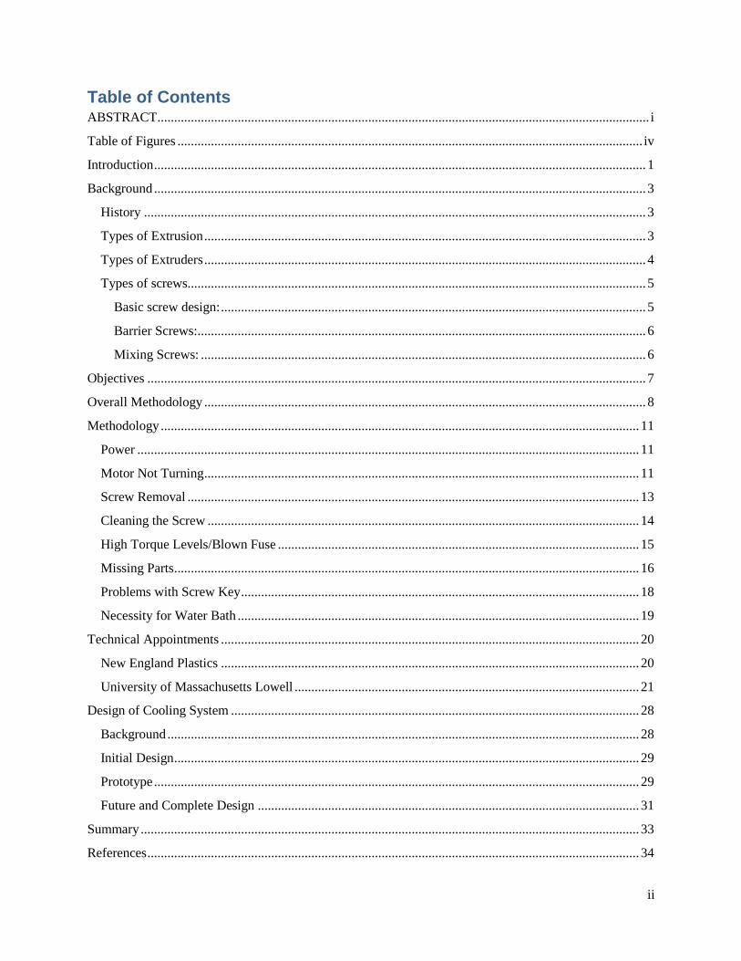
Table of Contents ABSTRACT ................................................................................................................................................... i
Table of Figures ........................................................................................................................................... iv
Introduction ................................................................................................................................................... 1
Background ................................................................................................................................................... 3
History ...................................................................................................................................................... 3
Types of Extrusion .................................................................................................................................... 3
Types of Extruders .................................................................................................................................... 4
Types of screws......................................................................................................................................... 5
Basic screw design: ............................................................................................................................... 5
Barrier Screws: ...................................................................................................................................... 6
Mixing Screws: ..................................................................................................................................... 6
Objectives ..................................................................................................................................................... 7
Overall Methodology .................................................................................................................................... 8
Methodology ............................................................................................................................................... 11
Power ...................................................................................................................................................... 11
Motor Not Turning .................................................................................................................................. 11
Screw Removal ....................................................................................................................................... 13
Cleaning the Screw ................................................................................................................................. 14
High Torque Levels/Blown Fuse ............................................................................................................ 15
Missing Parts ........................................................................................................................................... 16
Problems with Screw Key ....................................................................................................................... 18
Necessity for Water Bath ........................................................................................................................ 19
Technical Appointments ............................................................................................................................. 20
New England Plastics ............................................................................................................................. 20
University of Massachusetts Lowell ....................................................................................................... 21
Design of Cooling System .......................................................................................................................... 28
Background ............................................................................................................................................. 28
Initial Design ........................................................................................................................................... 29
Prototype ................................................................................................................................................. 29
Future and Complete Design .................................................................................................................. 31
Summary ..................................................................................................................................................... 33
References ................................................................................................................................................... 34

iii
Appendices .................................................................................................................................................. 35
Appendix A ............................................................................................................................................. 35
Appendix B ............................................................................................................................................. 41
iv
Table of Figures Figure 1 Single Screw Figure 2 Twin Screw........................................................................................... 4
Figure 3 Typical Screw ................................................................................................................................. 5
Figure 4 Conventional Barrier Screw ........................................................................................................... 6
Figure 5 Gear Box ......................................................................................................................................... 8
Figure 6 New Outlet ...................................................................................................................................... 9
Figure 7 220 Volt 30 Amp Power Plug ....................................................................................................... 11
Figure 8 Unattached Motor ......................................................................................................................... 12
Figure 9 Screw Removed ............................................................................................................................ 13
Figure 10 Dirty Screw ................................................................................................................................. 14
Figure 11 Clean Screw ................................................................................................................................ 14
Figure 12 Motor Controller ......................................................................................................................... 16
Figure 14 Bung Attached to Barrel ............................................................................................................. 17
Figure 13 Thermocouple Bung ................................................................................................................... 17
Figure 15 Nonfunctional Speed Gage Figure 16 Missing Gasket for Speed Gage ................................. 18
Figure 17 Screw Key .................................................................................................................................. 18
Figure 18 Sagging Molten Plastic From Die .............................................................................................. 19
Figure 19 Close-up of Die ........................................................................................................................... 20
Figure 20 Removed Die from Die Plate ...................................................................................................... 23
Figure 21 Pressure Transducer .................................................................................................................... 24
Figure 22 Our Manual Adjustable Temperature Figure 23 Umass Digital Adjustable Temperature .... 25
Figure 24 Resin Close up Figure 25 Bag of Polypropylene Received .................................................. 26
Figure 26 Brass Tools Received from Umass ............................................................................................. 26
Figure 27 Schematic Outline of Polymer Dynamics in Die Swell .............................................................. 28
Figure 28 CAD Drawing Top View ............................................................................................................ 29
Figure 29 CAD Drawing Front View Figure 30 CAD Drawing Side View ...................................... 30
Figure 31 Cooling System Prototype .......................................................................................................... 30
Figure 32 Close-up of Prototype ................................................................................................................. 31
Figure 33 Power Switch Figure 34 Digital Temperature Gage ............................................................ 37
Figure 35 Die Bolted on .............................................................................................................................. 37
Figure 36 Threaded End Cap Figure 37 Close Up of End Cap ............................................................. 38
Figure 38 Threaded Rob in End Cap .......................................................................................................... 38
Figure 39 End Cap Removed ...................................................................................................................... 38
Figure 40 Hammer Hitting Threaded Rod .................................................................................................. 39
Figure 41 Screw Removed .......................................................................................................................... 39
Figure 42 Screw Key .................................................................................................................................. 40
Figure 43 Brass Tool Against Screw .......................................................................................................... 40
1
Introduction
The extrusion process began in the 1800s by means of preheating the metal and forcing it
through a die via a hand driven plunger known as squirting. Extrusion is now possible for metals,
polymers, ceramics and concrete. Plastic extrusion began in the 1930s and the continuous
process has been applied to manufacturing at high volume. Plastics have been very popular in
the modern world and learning about the process interested us from the start. Learning about how
pellets can be heated and formed into the desired shape through a die is important for the process
to be improved upon. Learning the process and troubleshooting using our skills of engineering
to reverse engineer the extruder has been a true challenge. Upon the completion of this project
future students who are interested in extruded plastics will be given the opportunity to test
material properties and learn the ins and outs of how an extruder works.
Fixing this single screw extruder isn’t our only task as we implemented design also.
When given the extruder the motor wouldn’t run and there wasn’t a cooling system for the
extruded product. Design of a water bath seemed to be the simplest and most effective way to
cool the extruded plastic. When the material originally comes out hot and gravity pulls the
material down which makes it stretch and lose its shape. With a roller system and water bath the
material will strengthen and keep the desired shape. A place to store and organize the extruded
material is also necessary since the extrusion process is continuous and lasts up to an hour,
depending on the amount of material put into the hopper.
Another reason for this project is for future students to be able to run material properties
testing on different resins and comparing the results. Fixing the extruder benefits others by
giving them our troubleshooting process, videos of taking the extruder apart, CAD drawings and

2
model, pamphlet of how extruders work and a water bath cooling system. Completion of this
project will give us a great deal of knowledge of experience in the engineering field, knowledge
of the extrusion process and troubleshooting skills for the future.
3
Background
History
To properly troubleshoot and repair an extruder we must first understand what a plastic
extruder is. Plastic extrusion is used to create a multitude of different products ranging from
garbage bags to plastic tubing. Extrusion has been around as early as the 1800s known at that
time as squirting. Extrusion comes in three different forms; direct, indirect and hydrostatic which
all have their pros and cons. The type of extrusion we are studying is direct extrusion, also
known as forward extrusion, and is the most popular of the three forms of extrusion. It is the
process of moving material through a die of the desired shape of the cross-section. An extruder
works by melting down plastic pellets, called resin, that are then forced down a barrel by a screw
where they continue to melt and are finally pushed out through a die that gives them their final
shape. The extrusion process can be continuous, potentially producing any desired length of
material, or semi continuous to produce many pieces of material. The process may be hot or
cold.
Types of Extrusion
The other two types of extrusion mentioned earlier are indirect and hydrostatic. Indirect
extrusion, also known as backward extrusion, keeps the die stationary while the billet, heated
material which profiles are extruded, and the container move together. The length of the stem,
place where the die is held, is the potential maximum length the extrusion can be. With indirect
extrusion friction is much less which increases the speed of the process and ability to extrude
more small and challenging profiles. Impurities or defects in surface of billet will affect the
extrusion therefore billets are very important and need to be taken care of. The last type of
4
extrusion is hydrostatic extrusion which utilizes pressurized liquid around the billet and can be
done as hot, warm or cold. Process must be concealed to contain the hydrostatic medium. The
two ways to pressurize the fluid are constant-rate and constant-pressure. Constant-rate extrusion
uses a ram or plunger to pressurize the fluid in the container while constant-pressure uses a pump
to pressurize the fluid and then pump it into the container.
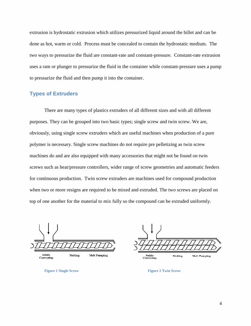
Types of Extruders
There are many types of plastics extruders of all different sizes and with all different
purposes. They can be grouped into two basic types; single screw and twin screw. We are,
obviously, using single screw extruders which are useful machines when production of a pure
polymer is necessary. Single screw machines do not require pre pelletizing as twin screw
machines do and are also equipped with many accessories that might not be found on twin
screws such as heat/pressure controllers, wider range of screw geometries and automatic feeders
for continuous production. Twin screw extruders are machines used for compound production
when two or more resigns are required to be mixed and extruded. The two screws are placed on
top of one another for the material to mix fully so the compound can be extruded uniformly.
Figure 1 Single Screw Figure 2 Twin Screw

5
Types of screws
Basic screw design:
The screw is usually contained inside a tight fitting barrel on the extruder. It is normally
driven by a variable speed motor and is a decidedly efficient device capable of processing
several tons of plastic per hour. The screw is divided into three zones: the feed zone, the
compression zone, and the metering zone.
The feed zone delivers plastic resin pellets from a gravity fed hopper into the barrel to
begin the longitudinal movement of the plastic. Using axial rotation the screw threads move the
plastic down the barrel. Within the barrel, heaters help the plastic develop a tack to increase its
friction against the barrel wall. Without this friction the plastic could not be conveyed forward
and would merely rotate inside the screw.
In the compression zone, also known as the transition or melt stage, the root diameter
of the screw increases while the height of the flight decreases. The resin is melted here because
of compression, shearing and heating produced in the barrel. Next the melted plastic moves
through the metering zone. In this zone the screw diameter remains constant and the melted
plastic which is under high pressure is pumped into the extruder die.
Figure 3 Typical Screw
6
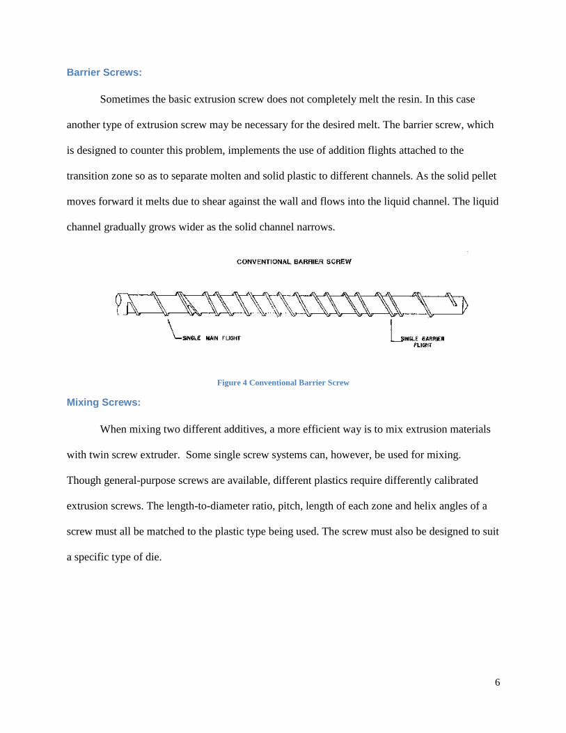
Barrier Screws:
Sometimes the basic extrusion screw does not completely melt the resin. In this case
another type of extrusion screw may be necessary for the desired melt. The barrier screw, which
is designed to counter this problem, implements the use of addition flights attached to the
transition zone so as to separate molten and solid plastic to different channels. As the solid pellet
moves forward it melts due to shear against the wall and flows into the liquid channel. The liquid
channel gradually grows wider as the solid channel narrows.
Figure 4 Conventional Barrier Screw
Mixing Screws:
When mixing two different additives, a more efficient way is to mix extrusion materials
with twin screw extruder. Some single screw systems can, however, be used for mixing.
Though general-purpose screws are available, different plastics require differently calibrated
extrusion screws. The length-to-diameter ratio, pitch, length of each zone and helix angles of a
screw must all be matched to the plastic type being used. The screw must also be designed to suit
a specific type of die.
7
Objectives
Understand the extrusion process works and gain knowledge about extruders
Disassemble and clean the extruder parts and troubleshoot it to ensure its proper operation
Design and construction of a cooling system as the plastic exits out of the die
Try to extrude various commercial resins
8
Overall Methodology
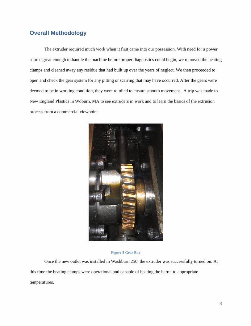
The extruder required much work when it first came into our possession. With need for a power
source great enough to handle the machine before proper diagnostics could begin, we removed the heating
clamps and cleaned away any residue that had built up over the years of neglect. We then proceeded to
open and check the gear system for any pitting or scarring that may have occurred. After the gears were
deemed to be in working condition, they were re-oiled to ensure smooth movement. A trip was made to
New England Plastics in Woburn, MA to see extruders in work and to learn the basics of the extrusion
process from a commercial viewpoint.
Figure 5 Gear Box
Once the new outlet was installed in Washburn 250, the extruder was successfully turned on. At
this time the heating clamps were operational and capable of heating the barrel to appropriate
temperatures.
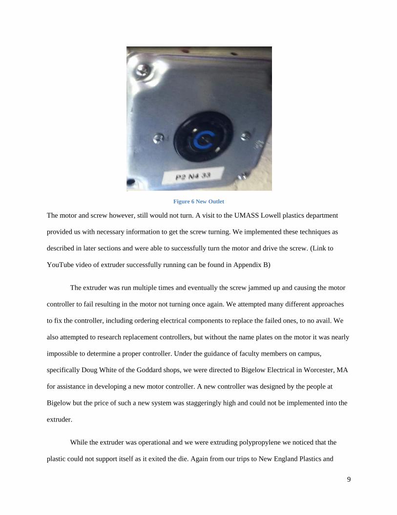
9
Figure 6 New Outlet
The motor and screw however, still would not turn. A visit to the UMASS Lowell plastics department
provided us with necessary information to get the screw turning. We implemented these techniques as
described in later sections and were able to successfully turn the motor and drive the screw. (Link to
YouTube video of extruder successfully running can be found in Appendix B)
The extruder was run multiple times and eventually the screw jammed up and causing the motor
controller to fail resulting in the motor not turning once again. We attempted many different approaches
to fix the controller, including ordering electrical components to replace the failed ones, to no avail. We
also attempted to research replacement controllers, but without the name plates on the motor it was nearly
impossible to determine a proper controller. Under the guidance of faculty members on campus,
specifically Doug White of the Goddard shops, we were directed to Bigelow Electrical in Worcester, MA
for assistance in developing a new motor controller. A new controller was designed by the people at
Bigelow but the price of such a new system was staggeringly high and could not be implemented into the
extruder.
While the extruder was operational and we were extruding polypropylene we noticed that the
plastic could not support itself as it exited the die. Again from our trips to New England Plastics and

10
UMASS Lowell, we were exposed to the use of water cooling systems for the molten plastic immediately
as they flow out of the die. We were able to design and build a much less sophisticated prototype water
cooling system to prevent the plastic from collapsing under its own weight. This system unfortunately
was not able to be tested due to the failure of the motor prior to its completion.
11
Methodology
Power
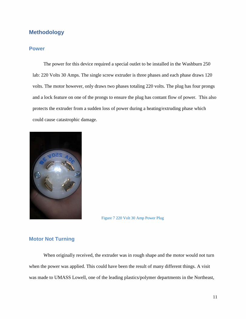
The power for this device required a special outlet to be installed in the Washburn 250
lab: 220 Volts 30 Amps. The single screw extruder is three phases and each phase draws 120
volts. The motor however, only draws two phases totaling 220 volts. The plug has four prongs
and a lock feature on one of the prongs to ensure the plug has contant flow of power. This also
protects the extruder from a sudden loss of power during a heating/extruding phase which
could cause catastrophic damage.
Figure 7 220 Volt 30 Amp Power Plug
Motor Not Turning
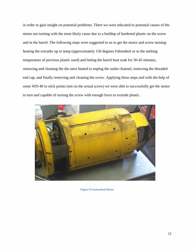
When originally received, the extruder was in rough shape and the motor would not turn
when the power was applied. This could have been the result of many different things. A visit
was made to UMASS Lowell, one of the leading plastics/polymer departments in the Northeast,
12
in order to gain insight on potential problems. There we were educated to potential causes of the
motor not turning with the most likely cause due to a buildup of hardened plastic on the screw
and in the barrel. The following steps were suggested to us to get the motor and screw turning:
heating the extruder up to temp (approximately 150 degrees Fahrenheit or to the melting
temperature of previous plastic used) and letting the barrel heat soak for 30-45 minutes,
removing and cleaning the die once heated to unplug the outlet channel, removing the threaded
end cap, and finally removing and cleaning the screw. Applying these steps and with the help of
some WD-40 in stick points (not on the actual screw) we were able to successfully get the motor
to turn and capable of turning the screw with enough force to extrude plastic.
Figure 8 Unattached Motor
13
Screw Removal
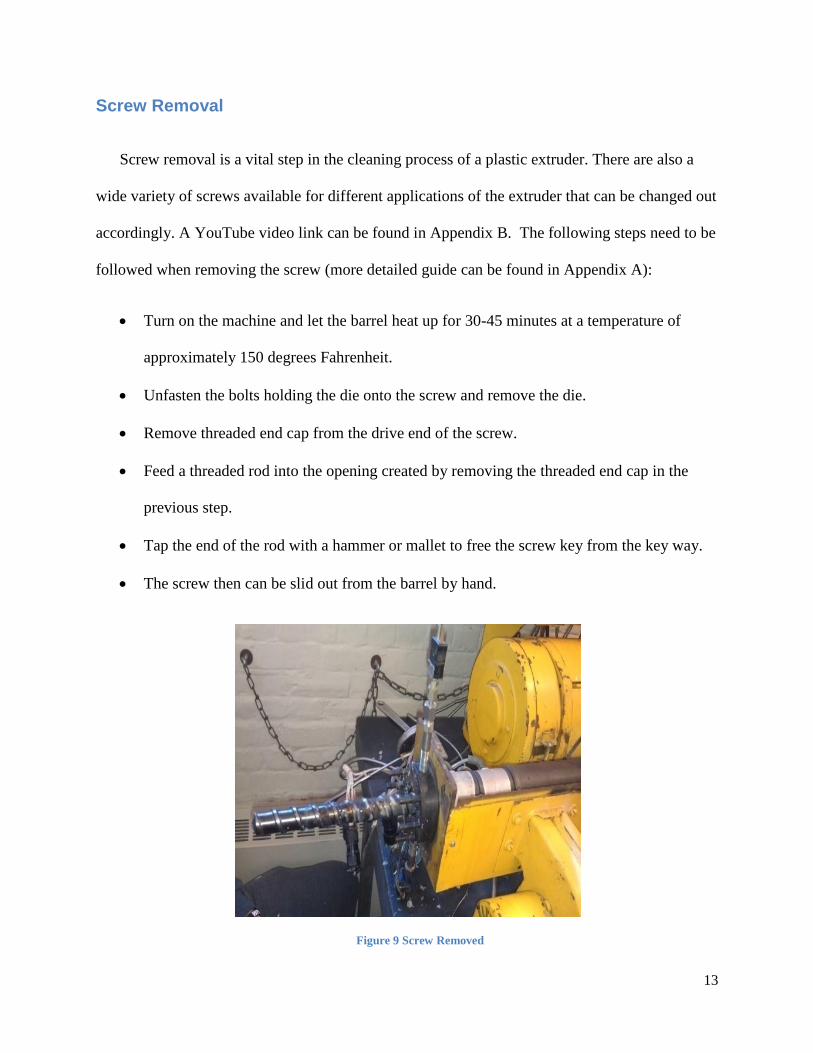
Screw removal is a vital step in the cleaning process of a plastic extruder. There are also a
wide variety of screws available for different applications of the extruder that can be changed out
accordingly. A YouTube video link can be found in Appendix B. The following steps need to be
followed when removing the screw (more detailed guide can be found in Appendix A):
Turn on the machine and let the barrel heat up for 30-45 minutes at a temperature of
approximately 150 degrees Fahrenheit.
Unfasten the bolts holding the die onto the screw and remove the die.
Remove threaded end cap from the drive end of the screw.
Feed a threaded rod into the opening created by removing the threaded end cap in the
previous step.
Tap the end of the rod with a hammer or mallet to free the screw key from the key way.
The screw then can be slid out from the barrel by hand.
Figure 9 Screw Removed
14
Cleaning the Screw
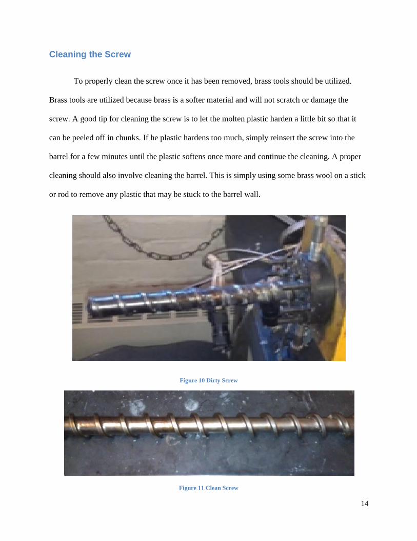
To properly clean the screw once it has been removed, brass tools should be utilized.
Brass tools are utilized because brass is a softer material and will not scratch or damage the
screw. A good tip for cleaning the screw is to let the molten plastic harden a little bit so that it
can be peeled off in chunks. If he plastic hardens too much, simply reinsert the screw into the
barrel for a few minutes until the plastic softens once more and continue the cleaning. A proper
cleaning should also involve cleaning the barrel. This is simply using some brass wool on a stick
or rod to remove any plastic that may be stuck to the barrel wall.
Figure 10 Dirty Screw
Figure 11 Clean Screw
15
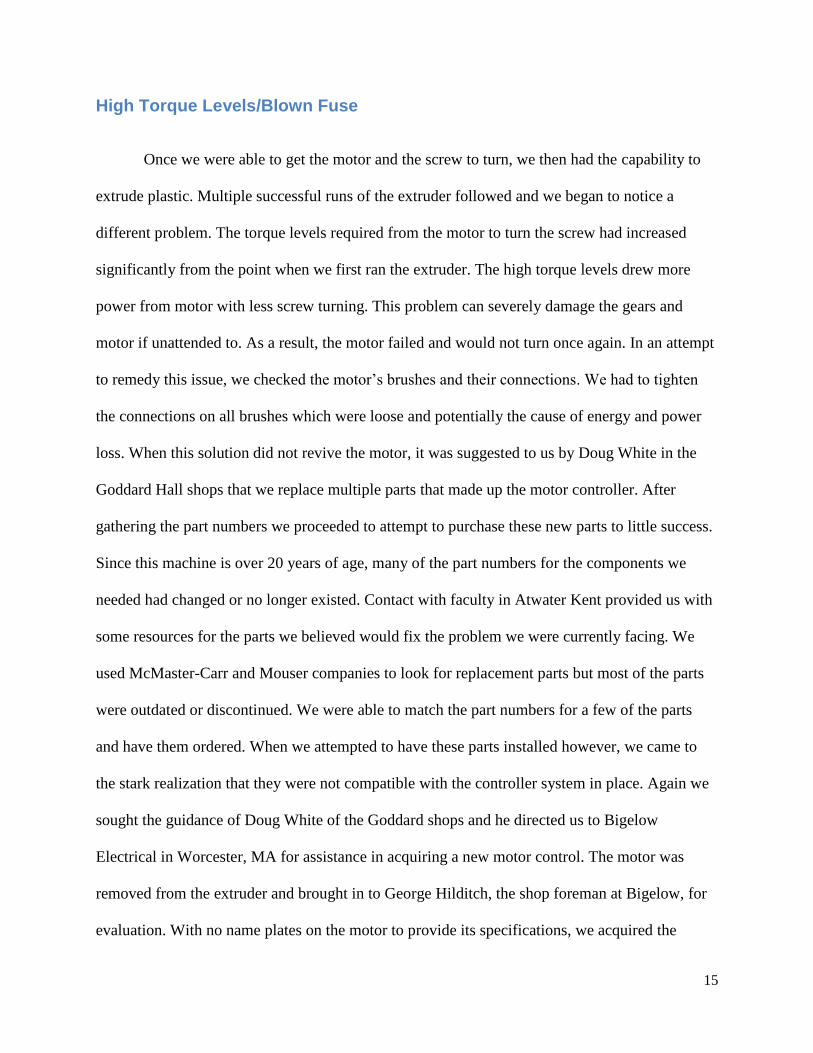
High Torque Levels/Blown Fuse
Once we were able to get the motor and the screw to turn, we then had the capability to
extrude plastic. Multiple successful runs of the extruder followed and we began to notice a
different problem. The torque levels required from the motor to turn the screw had increased
significantly from the point when we first ran the extruder. The high torque levels drew more
power from motor with less screw turning. This problem can severely damage the gears and
motor if unattended to. As a result, the motor failed and would not turn once again. In an attempt
to remedy this issue, we checked the motor’s brushes and their connections. We had to tighten
the connections on all brushes which were loose and potentially the cause of energy and power
loss. When this solution did not revive the motor, it was suggested to us by Doug White in the
Goddard Hall shops that we replace multiple parts that made up the motor controller. After
gathering the part numbers we proceeded to attempt to purchase these new parts to little success.
Since this machine is over 20 years of age, many of the part numbers for the components we
needed had changed or no longer existed. Contact with faculty in Atwater Kent provided us with
some resources for the parts we believed would fix the problem we were currently facing. We
used McMaster-Carr and Mouser companies to look for replacement parts but most of the parts
were outdated or discontinued. We were able to match the part numbers for a few of the parts
and have them ordered. When we attempted to have these parts installed however, we came to
the stark realization that they were not compatible with the controller system in place. Again we
sought the guidance of Doug White of the Goddard shops and he directed us to Bigelow
Electrical in Worcester, MA for assistance in acquiring a new motor control. The motor was
removed from the extruder and brought in to George Hilditch, the shop foreman at Bigelow, for
evaluation. With no name plates on the motor to provide its specifications, we acquired the
16
armature and field voltages that helped lead to discovering the revolutions per minute (3450),
and the horsepower (5). The motor was tested and found to be in good working condition
solidifying the theory that the motor controller was indeed the source of the problem. The
workers at Bigelow were able to spec out the correct motor controller but for a price far beyond
our budget.
Figure 12 Motor Controller
Missing Parts
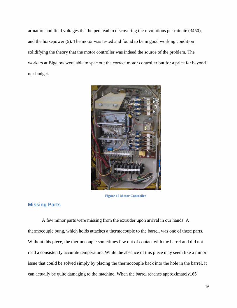
A few minor parts were missing from the extruder upon arrival in our hands. A
thermocouple bung, which holds attaches a thermocouple to the barrel, was one of these parts.
Without this piece, the thermocouple sometimes few out of contact with the barrel and did not
read a consistently accurate temperature. While the absence of this piece may seem like a minor
issue that could be solved simply by placing the thermocouple back into the hole in the barrel, it
can actually be quite damaging to the machine. When the barrel reaches approximately165
17
degrees Fahrenheit cooling fans kick on and blow air across the barrel to prevent overheating. If
the thermocouple was not reading the correct temperature of the barrel because it had fallen out,
the fans will not kick on to prevent the overheating. A new bung was purchased to remedy this
problem.
Figure 14 Bung Attached to Barrel
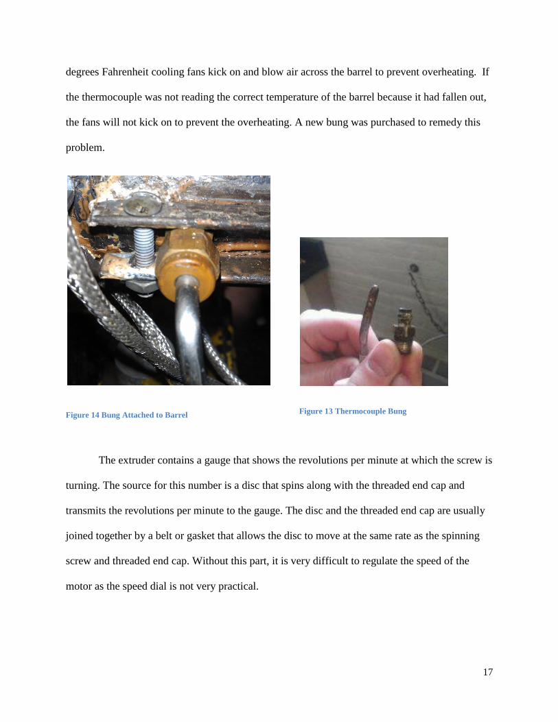
The extruder contains a gauge that shows the revolutions per minute at which the screw is
turning. The source for this number is a disc that spins along with the threaded end cap and
transmits the revolutions per minute to the gauge. The disc and the threaded end cap are usually
joined together by a belt or gasket that allows the disc to move at the same rate as the spinning
screw and threaded end cap. Without this part, it is very difficult to regulate the speed of the
motor as the speed dial is not very practical.
Figure 13 Thermocouple Bung
18
Figure 15 Nonfunctional Speed Gage Figure 16 Missing Gasket for Speed Gage
Problems with Screw Key
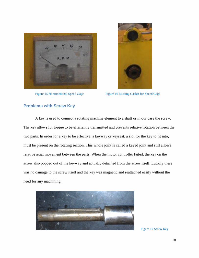
A key is used to connect a rotating machine element to a shaft or in our case the screw.
The key allows for torque to be efficiently transmitted and prevents relative rotation between the
two parts. In order for a key to be effective, a keyway or keyseat, a slot for the key to fit into,
must be present on the rotating section. This whole joint is called a keyed joint and still allows
relative axial movement between the parts. When the motor controller failed, the key on the
screw also popped out of the keyway and actually detached from the screw itself. Luckily there
was no damage to the screw itself and the key was magnetic and reattached easily without the
need for any machining.
Figure 17 Screw Key
19
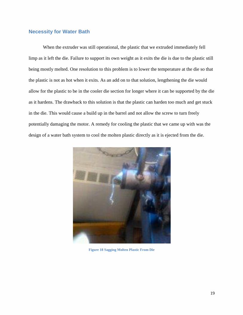
Necessity for Water Bath
When the extruder was still operational, the plastic that we extruded immediately fell
limp as it left the die. Failure to support its own weight as it exits the die is due to the plastic still
being mostly melted. One resolution to this problem is to lower the temperature at the die so that
the plastic is not as hot when it exits. As an add on to that solution, lengthening the die would
allow for the plastic to be in the cooler die section for longer where it can be supported by the die
as it hardens. The drawback to this solution is that the plastic can harden too much and get stuck
in the die. This would cause a build up in the barrel and not allow the screw to turn freely
potentially damaging the motor. A remedy for cooling the plastic that we came up with was the
design of a water bath system to cool the molten plastic directly as it is ejected from the die.
Figure 18 Sagging Molten Plastic From Die
20
Technical Appointments
New England Plastics
Our first extruding facility we paid a visit to was New England Plastics in Woburn,
Massachusetts. After planning an appointment with Tony we decided to make a binder of
pictures to present to each facility so whomever we spoke to could have a gist of what type of
extruder we are working with. After putting the pictures we desired on a USB drive, Rita was
generous and printed everything for us so that we could have a binder presentation of our project.
When we arrived at New England Plastics on December 13th
we were given a quick tour of their
facility. We were curious to see an extruder in use, receive simple troubleshooting tips, check
out different dies and possibly get an old one, see different screws and also possibly get an old
one, and also see if they have any referrals to other places willing to help.
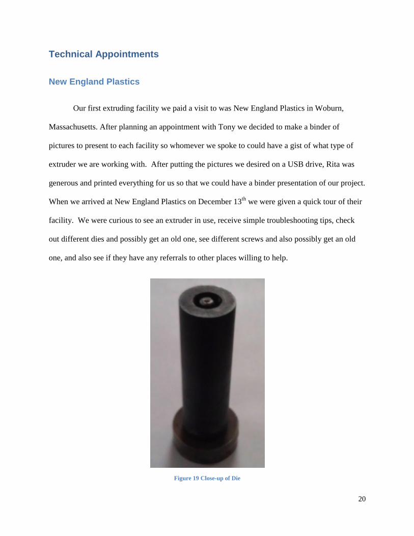
Figure 19 Close-up of Die
21
We were able to learn about the different parts of the extruder, see different dies and
learn how the die created the profile of the final product. Tony allowed us to take videos of
running extruders, although the extruders in their facility were all twin screws. This is where we
able to see the extruder create a final product of the compound made of different resins. All of
New England Plastics’ extruders were mixing or compound extruders while our extruder is used
for pure polymer extrusion. Tony was not able to help us too much on our extruder but helped us
understand the process a little better and see it for ourselves. We saw different types of dies used
in manufacturing and also different screws and how both of these parts play a big role in how the
extruder functions and what the final product looks like. He recommended getting a pamphlet,
or diagram, on single screw extruders to help us in the troubleshooting process.
The visit was short but the tour helped us understand the differences in extruders as well
as see them in use. Tony gave us a contact that could help fix our extruder, Davis Standard,
since he felt he couldn’t help us further.
University of Massachusetts Lowell
Our reverse engineering research led us to discover possible troubleshooting techniques
to solve our dilemma of the nonfunctional motor. Without being able to successfully remove the
motor or screw our troubleshooting became limited so we contacted the Plastics Department of
the University of Massachusetts Lowell for their guidance. Professor David Rondeau of Umass
Lowell, our primary contact, advised us to try to remove the screw which could be removed by
unlocking the key lock attached to the gear box. The screw could not be removed from the gear
box so he invited us for a visit of their plastics department as we provided further information
about our extruder and its problems. On December 16th
, 2011 we made a trip up to their Plastics
22
Department to met Professor Rondeau, Charles Currie who was a technician for Umass Lowell,
and Professor Orroth. The visit lasting several hours provided us with great details of exactly
how an extruder functions, pictures and a video (link can be found in Appendix B), and also
some materials to take back to WPI.
Professor Rondeau explained how extruders have a safety interlock and require a certain
temperature that must remain on for a period of time before the extruder can function properly.
Generally, an extruder needs a period of 45 minutes to warm up which allows the thermocouples
to set up and read correct and steady temperatures. This time allows the barrel and screw to soak
up in heat to melt plastic which could cause jamming or damaging results. Waiting another
twenty to thirty minutes will guarantee all material in the barrel is liquid and the screw can safely
be removed for cleaning. For the extruder machines in their department, the screw is removed by
pushing the screw inward and turning the screw clockwise which frees the screw from the gear
box. The screw can then be pushed out from the back as long as the die and die plate is removed
first. Proper cleaning of the screw is done so by fully removing the screw and using brass tools,
due to them being softer than steel, which will not scratch or damage the screw or barrel. After
the screw and barrel are fully cleaned the screw is placed back into the barrel and ready for use.
Professor Rondeau said this maintenance process must be preformed after every use of the
extruder for optimal performance.
Our next contact was with Professor Orroth who had been with the Umass Plastics
Department for many years. He used his wisdom and technical knowledge to explain how to
remove necessary parts to be able to remove the screw and motor. After we explained our
machine in some detail he recommended that it is necessary to take out all bolts and screws from

23
the die, so the screw can be accessible. The die is attached by the die plate which is held by six
bolts and screws all of which need to be removed.
Figure 20 Removed Die from Die Plate
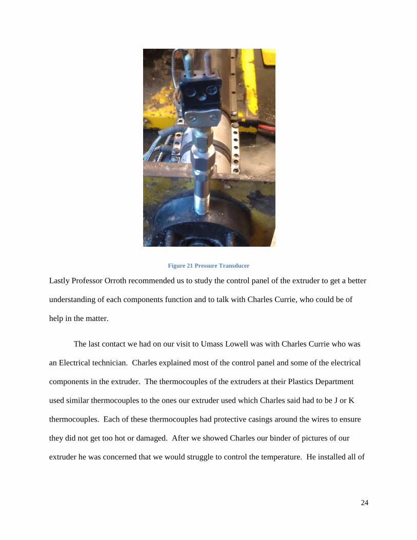
After the extruder is properly heated and ready then the screw can be fully removed. Professor
Orroth mentioned to avoid tempering with the pressure transducer because their extruders use the
readings of the pressure to detect any malfunctions and could automatically shut down the
extruder, if necessary. Because our pressure transducer is not attached to a computer hook up
this is not as important for our extruder since our table top extruder doesn’t read the pressures.
24
Figure 21 Pressure Transducer
Lastly Professor Orroth recommended us to study the control panel of the extruder to get a better
understanding of each components function and to talk with Charles Currie, who could be of
help in the matter.
The last contact we had on our visit to Umass Lowell was with Charles Currie who was
an Electrical technician. Charles explained most of the control panel and some of the electrical
components in the extruder. The thermocouples of the extruders at their Plastics Department
used similar thermocouples to the ones our extruder used which Charles said had to be J or K
thermocouples. Each of these thermocouples had protective casings around the wires to ensure
they did not get too hot or damaged. After we showed Charles our binder of pictures of our
extruder he was concerned that we would struggle to control the temperature. He installed all of
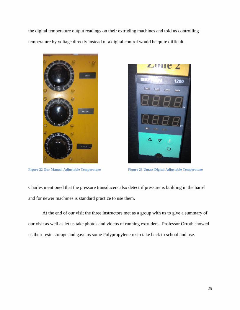
25
the digital temperature output readings on their extruding machines and told us controlling
temperature by voltage directly instead of a digital control would be quite difficult.
Figure 22 Our Manual Adjustable Temperature Figure 23 Umass Digital Adjustable Temperature
Charles mentioned that the pressure transducers also detect if pressure is building in the barrel
and for newer machines is standard practice to use them.
At the end of our visit the three instructors met as a group with us to give a summary of
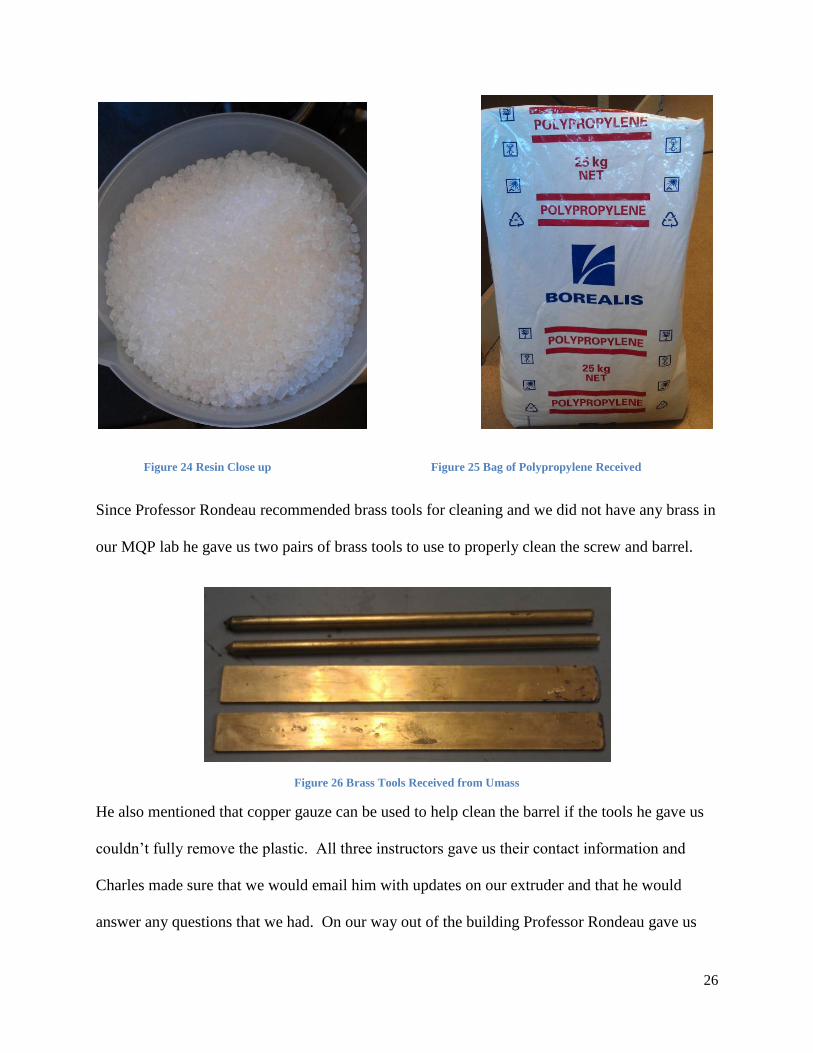
our visit as well as let us take photos and videos of running extruders. Professor Orroth showed
us their resin storage and gave us some Polypropylene resin take back to school and use.
26
Figure 24 Resin Close up Figure 25 Bag of Polypropylene Received
Since Professor Rondeau recommended brass tools for cleaning and we did not have any brass in
our MQP lab he gave us two pairs of brass tools to use to properly clean the screw and barrel.
Figure 26 Brass Tools Received from Umass
He also mentioned that copper gauze can be used to help clean the barrel if the tools he gave us
couldn’t fully remove the plastic. All three instructors gave us their contact information and
Charles made sure that we would email him with updates on our extruder and that he would
answer any questions that we had. On our way out of the building Professor Rondeau gave us

27
two books on extruders and the troubleshooting process on extruding machines. This was our
first reading material we received about single screw extruders and we knew it would come in
handy later in our project. Overall the visit was a huge help to our success with the extruder and
it was a great experience to see the University of Massachusetts Lowell’s impressive Plastics
Department.
28
Design of Cooling System
Background
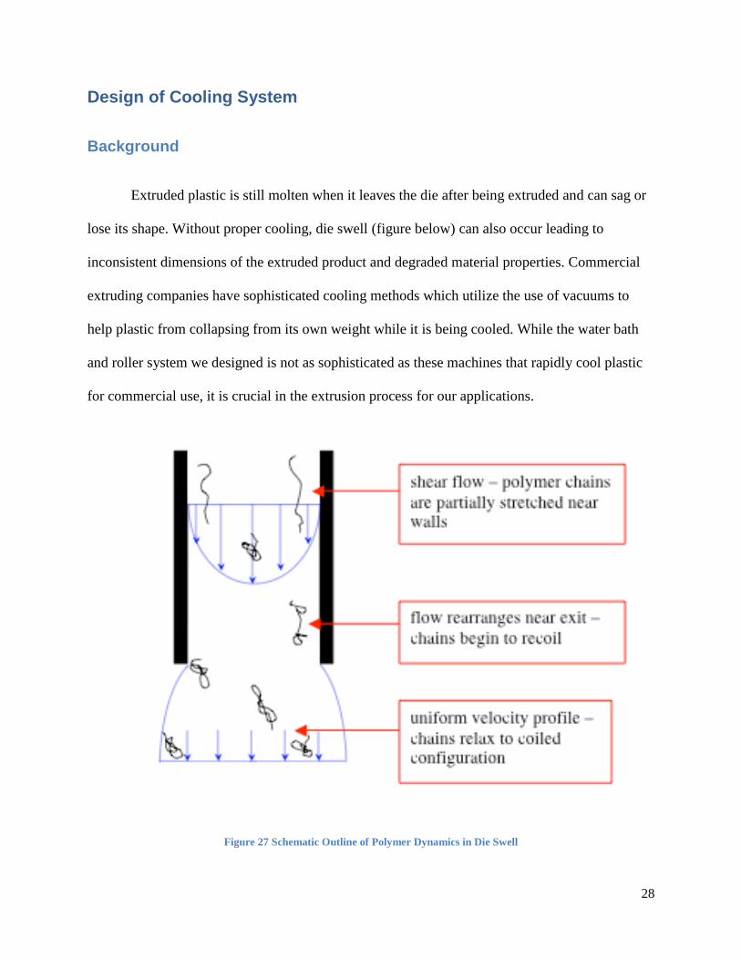
Extruded plastic is still molten when it leaves the die after being extruded and can sag or
lose its shape. Without proper cooling, die swell (figure below) can also occur leading to
inconsistent dimensions of the extruded product and degraded material properties. Commercial
extruding companies have sophisticated cooling methods which utilize the use of vacuums to
help plastic from collapsing from its own weight while it is being cooled. While the water bath
and roller system we designed is not as sophisticated as these machines that rapidly cool plastic
for commercial use, it is crucial in the extrusion process for our applications.
Figure 27 Schematic Outline of Polymer Dynamics in Die Swell
29
Initial Design
The initial design for a cooling system was to utilize a pumpless design that would not
recycle the water used. This system would contain a shower head like structure hooked up to a
water source by a hose. Once the water had showered over the molten plastic and collected in the
basin, it would flow through a drain and out of the system. We originally hoped to buy a roller
table and have the extruded plastic roll across it while being showered with water, but budget
and size constraints did not allow for a store bought table. As a result a homemade roller table
needed to be built.
Prototype
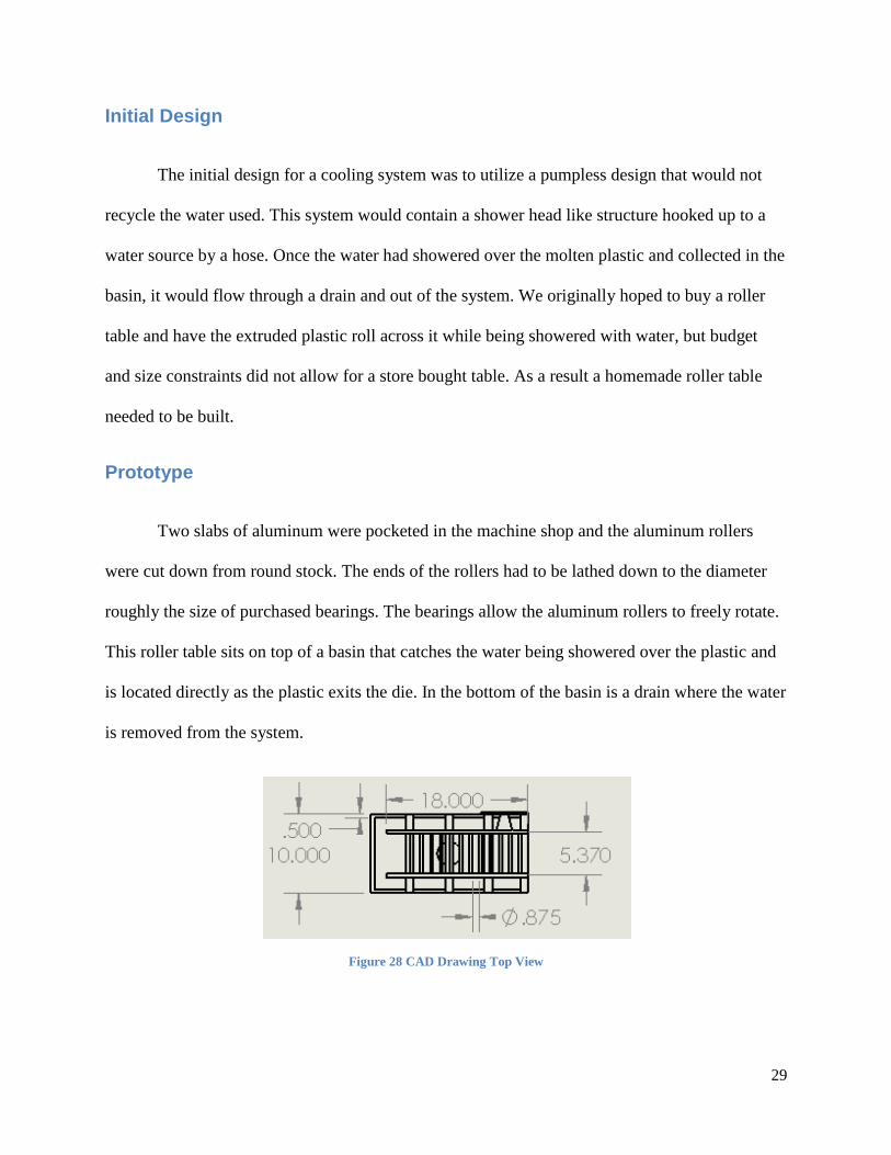
Two slabs of aluminum were pocketed in the machine shop and the aluminum rollers
were cut down from round stock. The ends of the rollers had to be lathed down to the diameter
roughly the size of purchased bearings. The bearings allow the aluminum rollers to freely rotate.
This roller table sits on top of a basin that catches the water being showered over the plastic and
is located directly as the plastic exits the die. In the bottom of the basin is a drain where the water
is removed from the system.
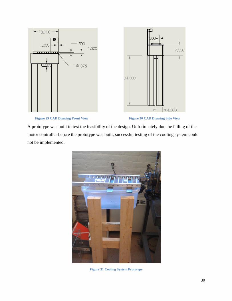
Figure 28 CAD Drawing Top View
30
Figure 29 CAD Drawing Front View Figure 30 CAD Drawing Side View
A prototype was built to test the feasibility of the design. Unfortunately due the failing of the
motor controller before the prototype was built, successful testing of the cooling system could
not be implemented.
Figure 31 Cooling System Prototype
31
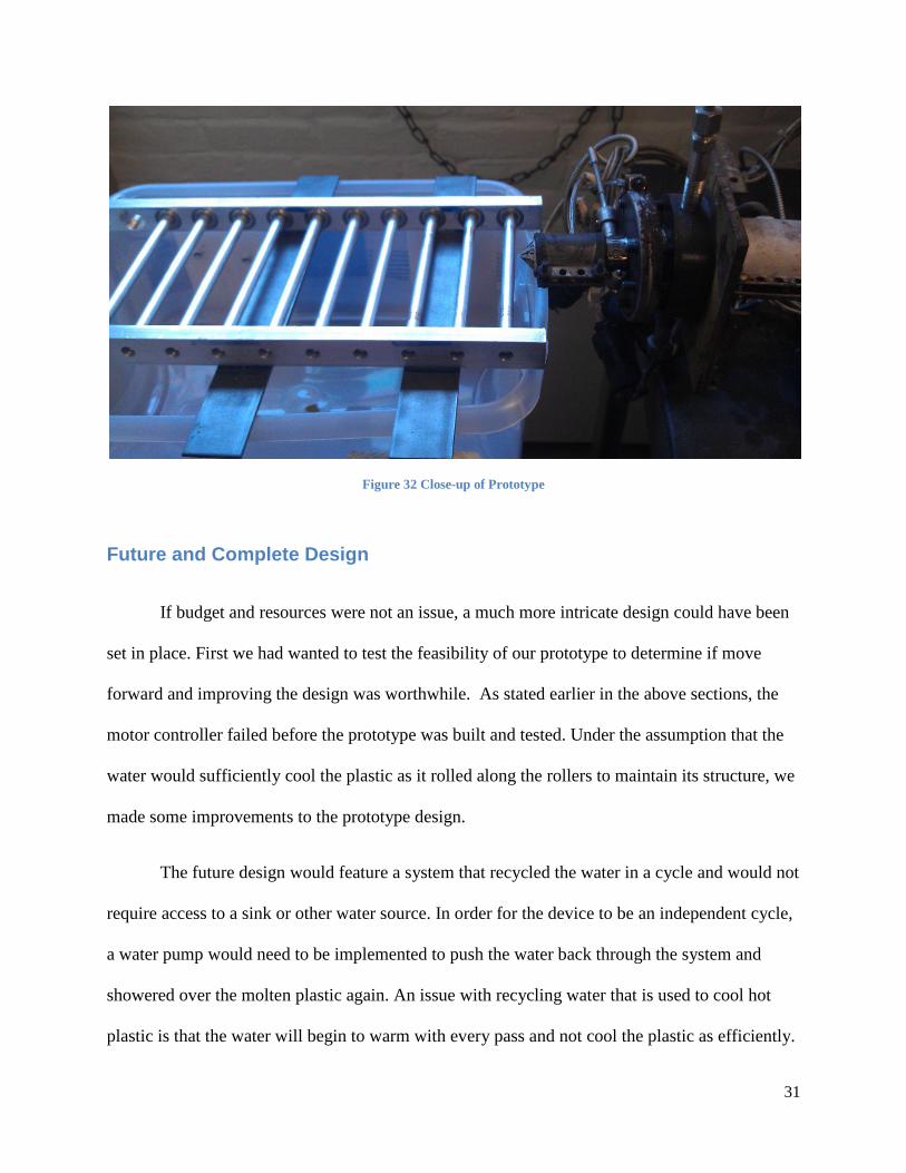
Figure 32 Close-up of Prototype
Future and Complete Design
If budget and resources were not an issue, a much more intricate design could have been
set in place. First we had wanted to test the feasibility of our prototype to determine if move
forward and improving the design was worthwhile. As stated earlier in the above sections, the
motor controller failed before the prototype was built and tested. Under the assumption that the
water would sufficiently cool the plastic as it rolled along the rollers to maintain its structure, we
made some improvements to the prototype design.
The future design would feature a system that recycled the water in a cycle and would not
require access to a sink or other water source. In order for the device to be an independent cycle,
a water pump would need to be implemented to push the water back through the system and
showered over the molten plastic again. An issue with recycling water that is used to cool hot
plastic is that the water will begin to warm with every pass and not cool the plastic as efficiently.

32
To remedy this, a small refrigerant cycle would need to be built equipped with a heat exchanger,
a compressor, a condenser and a pump or expansion valve.
Another improvement to the prototype design would be the implementation of proper
materials. Ideally the roller table and basin would be made of stainless steel to decrease the
chance of rust and also to improve the rigidity of the structure. Sturdy metallic legs would also
be implemented to ensure stability.

33
Summary
The major accomplishments of this project include the retrieval of the proper
specifications for a new motor controller, the design of a water cooling system, the replacement
of missing parts, the creation of a detailed screw removal and cleaning guide complete with
pictures of each step and a video of the process, and becoming educated with the extrusion
process. With no information available for this machine, learning how to properly use and run
the machine was a very tedious process.
As stated earlier, a cooling system is an integral part of the extrusion process. A
prototype water cooled system was designed and developed for placement immediately after the
die.
Also a very detailed screw removal and cleaning guide was also completed. This guide
contains a step by procedure for this process equipped with pictures (Appendix A). A video of
the process is also available through a YouTube link provided in Appendix B.
Finally a design of a new motor controller was also developed with the help of Bigelow
Electric in Worcester, MA. The new controller contains a digital control opposed to the arbitrary
knobs currently on the front of the extruder. Unfortunately, the high cost of the controller did not
allow for us to implement it into our project. However, Bigelow has supplied us with the
specifications for the new controller and a future project, most likely ECE, can use this
knowledge to finish the resurrection of the machine.
34
References
Bolur, P. c. (n.d.). A Guide to Injection Molding of Plastics. Retrieved January 15, 2012, from
http://www.pitfallsinmolding.com
Colby, P. N. (1978). Screw and Barrel Technology. Youngstown, Ohio: Spirex Corporation.
Industiralextrusionmachinery.com. (n.d.). Types of Plastic Extruders. Retrieved December 10,
2011, from http://industrialextrusionmachinery.com/types_of_plastic_extruders.html
McKinley, G. H. and MacMinn,(2004) C. W. Tubeless Siphon and Die Swell Demonstration.
Cambridge, Massachusetts: Massachusetts Institute of Technology
Nakajima, N. (Sep/Oct 1997) Plastics Extrusion Technology. Retrieved February 29, 2012.
<http://search.proquest.com/docview/220655939>
Screws, H. P. (2012).Patent#. http://www.sparproducts.com/Performance/high_performance.htm
Solutions, B. N. (n.d.). Comparing Twin Screw Extruders and Single Screw Extruders. Retrieved
December 21, 2011, from
http://www.machinerydata.com/ComparingTwinScrewextrudersandSingleScrewExtruders.htm
Whelan, T. and Goff, D.(1988) The Dynisco Extrusion Processors Handbook 2nd
Edition.
Dynisco Incorporated

35
Appendices
Appendix A
Stephen Jenkinson and John Kreso
Worcester Polytechnic Institute
Screw Removal and Cleaning Guide
36
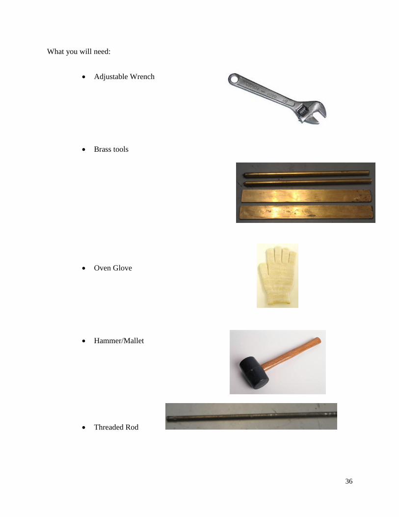
What you will need:
Adjustable Wrench
Brass tools
Oven Glove
Hammer/Mallet
Threaded Rod

37
The following steps need to be followed when removing the screw:
Turn on the machine and let the barrel heat up for 30-45 minutes at a temperature of
approximately 150 degrees Fahrenheit.
Figure 33 Power Switch Figure 34 Digital Temperature Gage
Unfasten the bolts holding the die onto the screw and remove the die (use an oven glove
as the die is very hot).
Figure 35 Die Bolted on
38
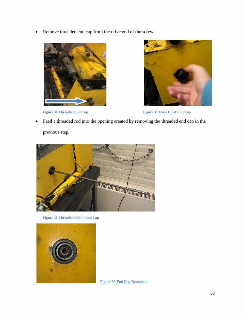
Remove threaded end cap from the drive end of the screw.
Figure 36 Threaded End Cap Figure 37 Close Up of End Cap
Feed a threaded rod into the opening created by removing the threaded end cap in the
previous step.
Figure 38 Threaded Rob in End Cap
Figure 39 End Cap Removed
39
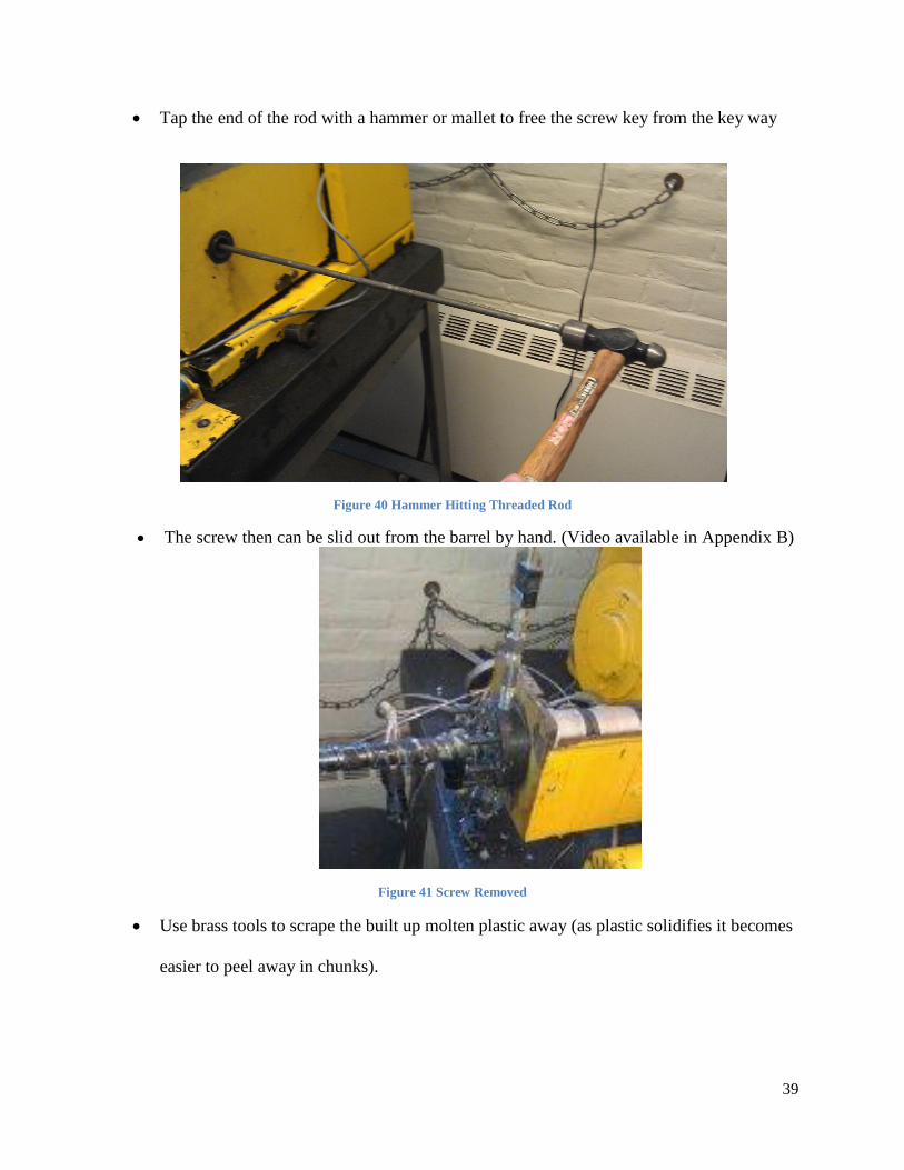
Tap the end of the rod with a hammer or mallet to free the screw key from the key way
Figure 40 Hammer Hitting Threaded Rod
The screw then can be slid out from the barrel by hand. (Video available in Appendix B)
Figure 41 Screw Removed
Use brass tools to scrape the built up molten plastic away (as plastic solidifies it becomes
easier to peel away in chunks).
40
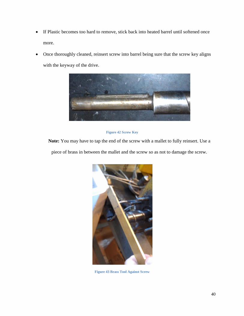
If Plastic becomes too hard to remove, stick back into heated barrel until softened once
more.
Once thoroughly cleaned, reinsert screw into barrel being sure that the screw key aligns
with the keyway of the drive.
Figure 42 Screw Key
Note: You may have to tap the end of the screw with a mallet to fully reinsert. Use a
piece of brass in between the mallet and the screw so as not to damage the screw.
Figure 43 Brass Tool Against Screw

41
Appendix B
Screw Removal YouTube Video
http://youtu.be/mUrihcYJDz4
Extruder Running YouTube Video
http://youtu.be/U9myL3ZQ4q0
Umass Lowell Extruder Running YouTube Video
http://youtu.be/GngTdLrthu8