Embed Size (px)
Citation preview

RED-D-ARC GX 300
IM10047-DAugust 2013
Red-D-Arc Spec-Built Welding EquipmentThis RED-D-ARC welder is built to RED-D-ARC Extreme Dutydesign specifications by Lincoln Electric.
Safety Depends on YouThis welder is designed and built with safety in mind.However, your overall safety can be increased by proper installation
... and thoughtful operation on your part.DO NOT INSTALL, OPERATE OR REPAIR THIS EQUIPMENT WITHOUT READING THIS MANUAL AND THE SAFETY PRECAUTIONS CONTAINED THROUGHOUT.And, most importantly, think before you act and be careful.
For use with machines having Code Numbers: 11678, 11740, 11795, 11802, 12098, 12204
The Global Leader in Welder Rentals
OPERATOR’S MANUAL
(

THANK YOU FOR SELECTING A QUALITY PRODUCT BY LINCOLN ELEC TRIC.
PLEASE EXAMINE CARTON AND EQUIPMENT FORDAMAGE IMMEDIATELY
When this equipment is shipped, title passes to the purchaserupon receipt by the carrier. Consequently, claims for materialdamaged in shipment must be made by the purchaser against thetransportation company at the time the shipment is received.
SAFETY DEPENDS ON YOU
Lincoln arc welding and cutting equipment is designed and builtwith safety in mind. However, your overall safety can be increasedby proper installation ... and thoughtful operation on your part. DO NOT INSTALL, OPERATE OR REPAIR THIS EQUIPMENT WITHOUT READING THIS MANUAL AND THE SAFETYPRECAUTIONS CONTAINED THROUGHOUT. And, most importantly,think before you act and be careful.
This statement appears where the information must be followedexactly to avoid serious personal injury or loss of life.
This statement appears where the information must be followedto avoid minor personal injury or damage to this equipment.
KEEP YOUR HEAD OUT OF THE FUMES.
DON’T get too close to the arc.Use corrective lenses if necessaryto stay a reasonable distanceaway from the arc.
READ and obey the Safety DataSheet (SDS) and the warning labelthat appears on all containers ofwelding materials.
USE ENOUGH VENTILATION orexhaust at the arc, or both, tokeep the fumes and gases from your breathing zone and the general area.
IN A LARGE ROOM OR OUTDOORS, natural ventilation may beadequate if you keep your head out of the fumes (See below).
USE NATURAL DRAFTS or fans to keep the fumes away from your face.
If you de velop unusual symptoms, see your supervisor. Perhaps the welding atmosphere and ventilation system should be checked.
WEAR CORRECT EYE, EAR & BODY PROTECTION
PROTECT your eyes and face with welding helmetproperly fitted and with proper grade of filter plate(See ANSI Z49.1).
PROTECT your body from welding spatter and arcflash with protective clothing including woolenclothing, flame-proof apron and gloves, leatherleggings, and high boots.
PROTECT others from splatter, flash, and glarewith protective screens or barriers.
IN SOME AREAS, protection from noise may be appropriate.
BE SURE protective equipment is in good condition.
Also, wear safety glasses in work areaAT ALL TIMES.
SPECIAL SITUATIONS
DO NOT WELD OR CUT containers or materials which previouslyhad been in contact with hazardous substances unless they areproperly cleaned. This is extremely dangerous.
DO NOT WELD OR CUT painted or plated parts unless specialprecautions with ventilation have been taken. They can releasehighly toxic fumes or gases.
Additional precautionary measures
PROTECT compressed gas cylinders from excessive heat,mechanical shocks, and arcs; fasten cylinders so they cannot fall.
BE SURE cylinders are never grounded or part of an electrical circuit.
REMOVE all potential fire hazards from welding area.
ALWAYS HAVE FIRE FIGHTING EQUIPMENT READY FORIMMEDIATE USE AND KNOW HOW TO USE IT.
WARNING
CAUTION
Safety 01 of 04 - 5/16/2018

SECTION A:WARNINGS
CALIFORNIA PROPOSITION 65 WARNINGS
WARNING: Breathing diesel engine exhaustexposes you to chemicals known to the Stateof California to cause cancer and birth defects,
or other reproductive harm.• Always start and operate the engine in a
well-ventilated area.• If in an exposed area, vent the exhaust to the outside.• Do not modify or tamper with the exhaust system. • Do not idle the engine except as necessary.For more information go to www.P65 warnings.ca.gov/diesel
WARNING: This product, when used for welding or
cutting, produces fumes or gases which contain
chemicals known to the State of California to cause
birth defects and, in some cases, cancer. (California
Health & Safety Code § 25249.5 et seq.)
WARNING: Cancer and Reproductive Harm
www.P65warnings.ca.gov
ARC WELDING CAN BE HAZARDOUS. PROTECTYOURSELF AND OTHERS FROM POSSIBLE SERIOUSINJURY OR DEATH. KEEP CHILDREN AWAY. PACEMAKER WEARERS SHOULD CONSULT WITHTHEIR DOCTOR BEFORE OPERATING.
Read and understand the following safety highlights. Foradditional safety information, it is strongly recommended that you purchase a copy of “Safety in Welding & Cutting - ANSI Standard Z49.1” from the American Welding Society, P.O. Box 351040, Miami, Florida 33135 or CSA Standard W117.2-1974. A Free copy of “Arc Welding Safety” booklet E205 is available from the Lincoln Electric Company, 22801 St. Clair Avenue, Cleveland, Ohio 44117-1199.
BE SURE THAT ALL INSTALLATION, OPERATION,MAINTENANCE AND REPAIR PROCEDURES AREPERFORMED ONLY BY QUALIFIED INDIVIDUALS.
FOR ENGINE POWEREDEQUIPMENT.
1.a. Turn the engine off before troubleshootingand maintenance work unless themaintenance work requires it to be running.
1.b. Operate engines in open, well-ventilated areas or vent the engineexhaust fumes outdoors.
1.c. Do not add the fuel near an open flame weldingarc or when the engine is running. Stop theengine and allow it to cool before refueling toprevent spilled fuel from vaporizing on contact
with hot engine parts and igniting. Do not spill fuel when fillingtank. If fuel is spilled, wipe it up and do not start engine untilfumes have been eliminated.
1.d. Keep all equipment safety guards, covers and devices in position and in good repair.Keep hands, hair, clothing and tools away from V-belts, gears, fans and all other moving parts when starting, operating orrepairing equipment.
1.e. In some cases it may be necessary to remove safety guards toperform required maintenance. Remove guards only whennecessary and replace them when the maintenance requiringtheir removal is complete. Always use the greatest care whenworking near moving parts.
1.f. Do not put your hands near the engine fan. Do not attempt tooverride the governor or idler by pushing on the throttle controlrods while the engine is running.
1.g. To prevent accidentally starting gasoline engines while turningthe engine or welding generator during maintenance work,disconnect the spark plug wires, distributor cap or magneto wireas appropriate.
1.h. To avoid scalding, do not remove the radiatorpressure cap when the engine is hot.
ELECTRIC ANDMAGNETIC FIELDS MAYBE DANGEROUS
2.a. Electric current flowing through any conductorcauses localized Electric and Magnetic Fields (EMF). Welding current creates EMF fields around welding cables and welding machines
2.b. EMF fields may interfere with some pacemakers, and welders having a pacemaker should consult their physicianbefore welding.
2.c. Exposure to EMF fields in welding may have other health effectswhich are now not known.
2.d. All welders should use the following procedures in order tominimize exposure to EMF fields from the welding circuit:
2.d.1. Route the electrode and work cables together - Securethem with tape when possible.
2.d.2. Never coil the electrode lead around your body.
2.d.3. Do not place your body between the electrode and workcables. If the electrode cable is on your right side, thework cable should also be on your right side.
2.d.4. Connect the work cable to the workpiece as close as pos-sible to the area being welded.
2.d.5. Do not work next to welding power source.
SAFETY
Safety 02 of 04 - 5/16/2018

ELECTRIC SHOCK CAN KILL.
3.a. The electrode and work (or ground) circuits areelectrically “hot” when the welder is on. Donot touch these “hot” parts with your bare skin or wet clothing.Wear dry, hole-free gloves to insulate hands.
3.b. Insulate yourself from work and ground using dry insulation.Make certain the insulation is large enough to cover your full areaof physical contact with work and ground.
In addition to the normal safety precautions, if
welding must be performed under electrically
hazardous conditions (in damp locations or while
wearing wet clothing; on metal structures such as
floors, gratings or scaffolds; when in cramped
positions such as sitting, kneeling or lying, if there
is a high risk of unavoidable or accidental contact
with the workpiece or ground) use the following
equipment:
• Semiautomatic DC Constant Voltage (Wire) Welder.
• DC Manual (Stick) Welder.
• AC Welder with Reduced Voltage Control.
3.c. In semiautomatic or automatic wire welding, the electrode,electrode reel, welding head, nozzle or semiautomatic weldinggun are also electrically “hot”.
3.d. Always be sure the work cable makes a good electricalconnection with the metal being welded. The connection shouldbe as close as possible to the area being welded.
3.e. Ground the work or metal to be welded to a good electrical (earth)ground.
3.f. Maintain the electrode holder, work clamp, welding cable andwelding machine in good, safe operating condition. Replacedamaged insulation.
3.g. Never dip the electrode in water for cooling.
3.h. Never simultaneously touch electrically “hot” parts of electrodeholders connected to two welders because voltage between thetwo can be the total of the open circuit voltage of bothwelders.
3.i. When working above floor level, use a safety belt to protectyourself from a fall should you get a shock.
3.j. Also see It ems 6.c. and 8.
ARC RAYS CAN BURN.
4.a. Use a shield with the proper filter and cover plates to protect youreyes from sparks and the rays of the arc when welding orobserving open arc welding. Headshield and filter lens shouldconform to ANSI Z87. I standards.
4.b. Use suitable clothing made from durable flame-resistant materialto protect your skin and that of your helpers from the arc rays.
4.c. Protect other nearby personnel with suitable, non-flammablescreening and/or warn them not to watch the arc nor exposethemselves to the arc rays or to hot spatter or metal.
FUMES AND GASESCAN BE DANGEROUS.
5.a. Welding may produce fumes and gaseshazardous to health. Avoid breathing thesefumes and gases. When welding, keep your head out of the fume.Use enough ventilation and/or exhaust at the arc to keep fumesand gases away from the breathing zone. When welding
hardfacing (see instructions on container or SDS)
or on lead or cadmium plated steel and other
metals or coatings which produce highly toxic
fumes, keep exposure as low as possible and
within applicable OSHA PEL and ACGIH TLV limits
using local exhaust or mechanical ventilation
unless exposure assessments indicate otherwise.
In confined spaces or in some circumstances,
outdoors, a respirator may also be required.
Additional precautions are also required when
welding
on galvanized steel.
5. b. The operation of welding fume control equipment is affected byvarious factors including proper use and positioning of theequipment, maintenance of the equipment and the specificwelding procedure and application involved. Worker exposurelevel should be checked upon installation and periodicallythereafter to be certain it is within applicable OSHA PEL andACGIH TLV limits.
5.c. Do not weld in locations near chlorinated hydrocarbon vaporscoming from degreasing, cleaning or spraying operations. Theheat and rays of the arc can react with solvent vapors to formphosgene, a highly toxic gas, and other irritating products.
5.d. Shielding gases used for arc welding can displace air and causeinjury or death. Always use enough ventilation, especially inconfined areas, to insure breathing air is safe.
5.e. Read and understand the manufacturer’s instructions for thisequipment and the consumables to be used, including theSafety Data Sheet (SDS) and follow your employer’s safetypractices. SDS forms are available from your weldingdistributor or from the manufacturer.
5.f. Also see item 1.b.
SAFETY
Safety 03 of 04 - 5/16/2018

WELDING AND CUTTINGSPARKS CAN CAUSEFIRE OR EXPLOSION.
6.a. Remove fire hazards from the welding area. Ifthis is not possible, cover them to prevent the welding sparksfrom starting a fire. Remember that welding sparks and hotmaterials from welding can easily go through small cracks andopenings to adjacent areas. Avoid welding near hydraulic lines.Have a fire extinguisher readily available.
6.b. Where compressed gases are to be used at the job site, specialprecautions should be used to prevent hazardous situations.Refer to “Safety in Welding and Cutting” (ANSI Standard Z49.1)and the operating information for the equipment being used.
6.c. When not welding, make certain no part of the electrode circuit istouching the work or ground. Accidental contact can causeoverheating and create a fire hazard.
6.d. Do not heat, cut or weld tanks, drums or containers until theproper steps have been taken to insure that such procedures will not cause flammable or toxic vapors from substances inside.They can cause an explosion even though they have been“cleaned”. For information, purchase “Recommended SafePractices for the Preparation for Welding and Cutting ofContainers and Piping That Have Held Hazardous Substances”,AWS F4.1 from the American Welding Society (see address above).
6.e. Vent hollow castings or containers before heating, cutting orwelding. They may explode.
6.f. Sparks and spatter are thrown from the welding arc. Wear oil freeprotective garments such as leather gloves, heavy shirt, cufflesstrousers, high shoes and a cap over your hair. Wear ear plugswhen welding out of position or in confined places. Always wearsafety glasses with side shields when in a welding area.
6.g. Connect the work cable to the work as close to the welding areaas practical. Work cables connected to the building framework orother locations away from the welding area increase thepossibility of the welding current passing through lifting chains,crane cables or other alternate circuits. This can create firehazards or overheat lifting chains or cables until they fail.
6.h. Also see item 1.c.
6.I. Read and follow NFPA 51B “Standard for Fire Prevention DuringWelding, Cutting and Other Hot Work”, available from NFPA, 1Batterymarch Park, PO box 9101, Quincy, MA 022690-9101.
6.j. Do not use a welding power source for pipe thawing.
CYLINDER MAY EXPLODE IFDAMAGED.
7.a. Use only compressed gas cylinders containingthe correct shielding gas for the process usedand properly operating regulators designed forthe gas and pressure used. All hoses, fittings,etc. should be suitable for the application andmaintained in good condition.
7.b. Always keep cylinders in an upright position securely chained toan undercarriage or fixed support.
7.c. Cylinders should be located:
• Away from areas where they may be struck or subjectedto physical damage.
• A safe distance from arc welding or cutting operationsand any other source of heat, sparks, or flame.
7.d. Never allow the electrode, electrode holder or any otherelectrically “hot” parts to touch a cylinder.
7.e. Keep your head and face away from the cylinder valve outletwhen opening the cylinder valve.
7.f. Valve protection caps should always be in place and hand tightexcept when the cylinder is in use or connected for use.
7.g. Read and follow the instructions on compressed gas cylinders,associated equipment, and CGA publication P-l, “Precautions forSafe Handling of Compressed Gases in Cylinders,” available fromthe Compressed Gas Association, 14501 George Carter WayChantilly, VA 20151.
FOR ELECTRICALLYPOWERED EQUIPMENT.
8.a. Turn off input power using the disconnectswitch at the fuse box before working on the equipment.
8.b. Install equipment in accordance with the U.S. National ElectricalCode, all local codes and the manufacturer’s recommendations.
8.c. Ground the equipment in accordance with the U.S. NationalElectrical Code and the manufacturer’s recommendations.
Refer to
http://www.lincolnelectric.com/safety
for additional safety information.
SAFETY
Safety 04 of 04 - 5/16/2018
ivSAFETYiv
GX 300
PRÉCAUTIONS DE SÛRETÉPour votre propre protection lire et observer toutes les instructionset les précautions de sûreté specifiques qui parraissent dans cemanuel aussi bien que les précautions de sûreté générales suiv-antes:
Sûreté Pour Soudage A LʼArc1. Protegez-vous contre la secousse électrique:
a. Les circuits à lʼélectrode et à la piéce sont sous tensionquand la machine à souder est en marche. Eviter toujourstout contact entre les parties sous tension et la peau nueou les vétements mouillés. Porter des gants secs et sanstrous pour isoler les mains.
b. Faire trés attention de bien sʼisoler de la masse quand onsoude dans des endroits humides, ou sur un planchermetallique ou des grilles metalliques, principalement dans les positions assis ou couché pour lesquelles une grandepartie du corps peut être en contact avec la masse.
c. Maintenir le porte-électrode, la pince de masse, le câblede soudage et la machine à souder en bon et sûr étatdefonctionnement.
d.Ne jamais plonger le porte-électrode dans lʼeau pour lerefroidir.
e. Ne jamais toucher simultanément les parties sous tensiondes porte-électrodes connectés à deux machines à souderparce que la tension entre les deux pinces peut être letotal de la tension à vide des deux machines.
f. Si on utilise la machine à souder comme une source decourant pour soudage semi-automatique, ces precautionspour le porte-électrode sʼapplicuent aussi au pistolet desoudage.
2. Dans le cas de travail au dessus du niveau du sol, se protégercontre les chutes dans le cas ou on recoit un choc. Ne jamaisenrouler le câble-électrode autour de nʼimporte quelle partiedu corps.
3. Un coup dʼarc peut être plus sévère quʼun coup de soliel,donc:
a. Utiliser un bon masque avec un verre filtrant appropriéainsi quʼun verre blanc afin de se protéger les yeux du ray-onnement de lʼarc et des projections quand on soude ouquand on regarde lʼarc.
b. Porter des vêtements convenables afin de protéger lapeau de soudeur et des aides contre le rayonnement delʻarc.
c. Protéger lʼautre personnel travaillant à proximité ausoudage à lʼaide dʼécrans appropriés et non-inflammables.
4. Des gouttes de laitier en fusion sont émises de lʼarc desoudage. Se protéger avec des vêtements de protection libresde lʼhuile, tels que les gants en cuir, chemise épaisse, pan-talons sans revers, et chaussures montantes.
5. Toujours porter des lunettes de sécurité dans la zone desoudage. Utiliser des lunettes avec écrans lateraux dans leszones où lʼon pique le laitier.
6. Eloigner les matériaux inflammables ou les recouvrir afin deprévenir tout risque dʼincendie dû aux étincelles.
7. Quand on ne soude pas, poser la pince à une endroit isolé dela masse. Un court-circuit accidental peut provoquer unéchauffement et un risque dʼincendie.
8. Sʼassurer que la masse est connectée le plus prés possiblede la zone de travail quʼil est pratique de le faire. Si on placela masse sur la charpente de la construction ou dʼautresendroits éloignés de la zone de travail, on augmente le risquede voir passer le courant de soudage par les chaines de lev-age, câbles de grue, ou autres circuits. Cela peut provoquerdes risques dʼincendie ou dʼechauffement des chaines et descâbles jusquʼà ce quʼils se rompent.
9. Assurer une ventilation suffisante dans la zone de soudage.Ceci est particuliérement important pour le soudage de tôlesgalvanisées plombées, ou cadmiées ou tout autre métal quiproduit des fumeés toxiques.
10. Ne pas souder en présence de vapeurs de chlore provenantdʼopérations de dégraissage, nettoyage ou pistolage. Lachaleur ou les rayons de lʼarc peuvent réagir avec les vapeursdu solvant pour produire du phosgéne (gas fortement toxique)ou autres produits irritants.
11. Pour obtenir de plus amples renseignements sur la sûreté,voir le code “Code for safety in welding and cutting” CSAStandard W 117.2-1974.
PRÉCAUTIONS DE SÛRETÉ POURLES MACHINES À SOUDER ÀTRANSFORMATEUR ET ÀREDRESSEUR
1. Relier à la terre le chassis du poste conformement au code delʼélectricité et aux recommendations du fabricant. Le dispositifde montage ou la piece à souder doit être branché à unebonne mise à la terre.
2. Autant que possible, Iʼinstallation et lʼentretien du poste seronteffectués par un électricien qualifié.
3. Avant de faires des travaux à lʼinterieur de poste, la debranch-er à lʼinterrupteur à la boite de fusibles.
4. Garder tous les couvercles et dispositifs de sûreté à leurplace.
vi vi TABLE OF CONTENTSPage
Installation.......................................................................................................................Section ATechnical Specifications.......................................................................................................A-1Machine Specifications ........................................................................................................A-2
Safety Precautions ........................................................................................................A-3Location and Ventilation................................................................................................A-3Stacking ........................................................................................................................A-3Angle of Operation ........................................................................................................A-3Lifting.............................................................................................................................A-3Additional Safety Precautions .......................................................................................A-3High Altitude Operation .................................................................................................A-3High Temperature Operation ........................................................................................A-3Towing...........................................................................................................................A-3Vehicle Mounting...........................................................................................................A-4
Pre-Operation Engine Service..............................................................................................A-4Oil ..................................................................................................................................A-4Fuel ...............................................................................................................................A-4Engine Coolant..............................................................................................................A-4Battery Connections......................................................................................................A-4Muffler Outlet Pipe ........................................................................................................A-4Spark Arrester ...............................................................................................................A-4High Frequency Generators for Tig Applications ..........................................................A-5Remote Control .............................................................................................................A-5
Electrical Connections..........................................................................................................A-5Machine Grounding.......................................................................................................A-5Welding Terminals ........................................................................................................A-5Welding Output Cables .................................................................................................A-5Cable Installation...........................................................................................................A-6
Auxiliary Power Receptacles and Plugs...............................................................................A-6Standby Power Connections ................................................................................................A-6Premises Wiring ...................................................................................................................A-7Connection of Lincoln Electric Wire Feeders .......................................................................A-8
_______________________________________________________________________________Operation.........................................................................................................................Section B
Safety Precautions ..............................................................................................................B-1General Description..............................................................................................................B-1Design Features ...................................................................................................................B-1Engine Operation..................................................................................................................B-1Fuel ......................................................................................................................................B-1
Welder Controls ............................................................................................................B-2Engine Controls.............................................................................................................B-3Starting and Stopping the Engine .................................................................................B-3Stopping .......................................................................................................................B-4
Welding Operation................................................................................................................B-4DC Stick Welding ..........................................................................................................B-4Constant Current (Stick) Welding..................................................................................B-4Pipe Welding .................................................................................................................B-4Fuel Consumption .........................................................................................................B-4Tig Welding ...................................................................................................................B-5Typical Current Ranges for Tungsten Electrodes .........................................................B-5Wire Welding-CV...........................................................................................................B-5Arc Gouging ..................................................................................................................B-6Auxiliary Power .............................................................................................................B-6Simultaneous Welding and Auxiliary Power Loads.......................................................B-6Extension Cord Recommendations...............................................................................B-6
________________________________________________________________________Accessories .....................................................................................................Section C
Options / Accessories and Compatible Lincoln Equipment.................................................C-1________________________________________________________________________________

vii viiTABLE OF CONTENTSMaintenance......................................................................................................Section D
Safety Precautions ................................................................................................D-1Routine Maintenance ............................................................................................D-1Kohler Engine........................................................................................................D-1Engine Maintenance Components ........................................................................D-1
Engine Oil Change..........................................................................................D-2Engine Oil Refill Capacities.............................................................................D-2Oil Filter Change .............................................................................................D-2Air Cleaner Service .........................................................................................D-2Air Pre-Cleaner Service ..................................................................................D-2
Air Filter Paper Element ........................................................................................D-3Spark Plug ......................................................................................................D-3Spark Plug Service .........................................................................................D-3Fuel Filter ........................................................................................................D-4Engine Adjustment ..........................................................................................D-4Battery Maintenance .......................................................................................D-4Servicing Optional Spark Arrestor ...................................................................D-4
Welder / Generator Maintenance ........................................................................D-5Storage ...........................................................................................................D-5Cleaning..........................................................................................................D-5Brush Removal and Replacement ..................................................................D-5GFCI Receptacle Testing and Resetting Procedure.......................................D-5
________________________________________________________________________Troubleshooting ..............................................................................................Section E
How to Use Troubleshooting Guide.......................................................................E-1Troubleshooting Guide ..........................................................................................E-2Troubleshooting Guide ..........................................................................................E-3Troubleshooting Guide ..........................................................................................E-4Troubleshooting Guide ..........................................................................................E-5
________________________________________________________________________Diagrams and Dimension Print ......................................................................Section F
________________________________________________________________________Parts List.................................................................................................................P-642
________________________________________________________________________

GX 300
1. Output rating in watts is equivalent to volt-amperes at unity power factor. Output voltage is within ± 10% at all loads up torated capacity. When welding, available auxiliary power will be reduced.
A-1INSTALLATION A-1
TECHNICAL SPECIFICATIONS - GX300 (K2284-2)INPUT - GASOLINE ENGINE
RATED OUTPUT @ 104° F (40° C) - WELDER
HEIGHT WIDTH DEPTH WEIGHT
30.00** in. 21.50 in 42.25 in.
762.0 mm 546.0 mm 1073.0 mm
LUBRICATION VALVE LIFTERS FUEL SYSTEM GOVERNORFull Pressure Hydraulic Mechanical Fuel Pump Mechanical Governorwith Full Flow Filter 5% Regulation
AIR CLEANER ENGINE IDLER MUFFLER ENGINE PROTECTIONLow noise Muffler: Top outlet Shutdown on low oil
Duel Element Automatic Idler can be rotated. Made from pressure.long life, aluminized steel.
ENGINE WARRANTY: 2 year unlimited hours (See engine manufacturer warranty for details.)Kohler
Welding Output Volts at Rated Amps Duty Cycle Max. OCV @ 3700 RPMCC STICK DC Output 29 Volts @ 305 Amps 100%CC STICK Output Range 20 to 305 Amps -------PIPE DC Output 29 Volts @ 300 Amps 100%PIPE Output Range 40 to 300 Amps -------Touch Start™ TIG Output Range 30 to 250 Amps 100% 60 VoltsTouch Start™ TIG Output Range 20 to 250 Amps -------CV WIRE DC Output 29 Volts @ 300 Amps 100%CV WIRE Output Range 14 to 29 volts -------
Auxiliary Power 1
10,000 Watts Peak, 9500 Watts Continuous, 60 Hz120/240 Volts
PHYSICAL DIMENSIONS
ENGINE COMPONENTS
RATED OUTPUT @ 104° F (40° C).- GENERATOR
Speed (RPM)
High Idle 3700
Full Load 3500
StartingSystem
12VDC Battery &Starter
(Group 58; 435Cold crank amps)Battery Charger
Displacementcu. In.(cu. Cm.)
41(674)
44.2(725)
Bore x Strokeinch (mm)
3.15 x 2.64(80 x 67)
3.27 x 2.64(83 x 67)
Make/Model
KohlerCH23SCH680
CH730
Description
2 cylinder
23 HP @ 3600 RPM GasolineEngine
Capacities
Fuel: 12 gal.45.4 L
Oil: 2.0 qt.1.9 ltr.
Codes 11802 and below463 lbs. (210kg.)
Code 12098 467 lbs. (212kg.)

A-2INSTALLATION A-2
GX 300
MACHINE SPECIFICATIONS - GX300 (K2284-2)
RECEPTACLES AUXILIARY POWER CIRCUIT BREAKER OTHER CIRCUIT BREAKERS
(2) 120VAC Duplex GFCI Two 20AMP for Two Duplex GFCI Receptacle 20AMP for Battery Charging Circuit(5-20R)(1) 120/240VAC Dual One 50AMP for Dual Voltage (2-Pole) 15AMP for 42V Wire Feeder PowerVoltage Full KVA (14-50R)
RECEPTACLES AND CIRCUIT BREAKERS

A-3INSTALLATION A-3LIFTINGThe GX 300 weighs approximately 539 lbs(244.5kg. Alift bail is mounted to the machine and should alwaysbe used when lifting the machine.
ADDITIONAL SAFETY PRECAUTIONS
• Lift only with equipment ofadequate lifting capacity.
• Be sure machine is stablewhen lifting.
• Do not lift this machine usinglift bale if it is equipped with aheavy accessory such as trail-er or gas cylinder.
FALLING • Do not lift machine if lift bale is
EQUIPMENT can damaged.
cause injury. • Do not operate machine while
suspended from lift bale.
------------------------------------------------------------------------HIGH ALTITUDE OPERATIONAt higher altitudes, output de-rating may be necessary. Formaximum rating, de-rate the welder output 3.5% for every 1000ft. (305m). Contact an authorized engine service shop for modi-fications to operate above 5,000 ft. (1524m).
HIGH TEMPERATURE OPERATIONAt temperatures above 40°C, Welder output derating is neces-sary. For maximum output ratings, derate the welder output 2volts for every 10°C above 40°C.
TOWINGThe recommended trailer for use with this equipment for road,in-plant and yard towing by a vehicle(1) is Lincolnʼs K957-1. Ifthe user adapts a non-Lincoln trailer, he must assume responsi-bility that the method of attachment and usage does not resultin a safety hazard nor damage the welding equipment. Some ofthe factors to be considered are as follows:
1. Design capacity of trailer vs. weight of Lincoln equipment andlikely additional attachments.
2. Proper support of, and attachment to, the base of the weld-ing equipment so there will be no undue stress to the frame-work.
3. Proper placement of the equipment on the trailer to insurestability side to side and front to back when being movedand when standing by itself while being operated or ser-viced.
4. Typical conditions of use, i.e., travel speed; roughness of sur-face on which the trailer will be operated; environmental con-ditions; like maintenance.
5. Conformance with federal, state and local laws.(1)
(1) Consult applicable federal, state and local laws regardingspecific requirements for use on public highways.
GX 300
SAFETY PRECAUTIONS
Only qualified personnel should install, use, or service this equipment.
LOCATION AND VENTILATIONThe welder should be located to provide an unrestrict-ed flow of clean, cool air to the cooling air inlets and toavoid restricting the cooling air outlets. Also, locate thewelder so that the engine exhaust fumes are properlyvented to an outside area.
STACKINGGX 300 machines cannot be stacked.
ANGLE OF OPERATIONEngines are designed to run in the level conditionwhich is where the optimum performance is achieved.The maximum angle of continuous operation is 15degrees in any direction. If the engine is to be operat-ed at an angle, provisions must be made for checkingand maintaining the oil level at the normal (FULL) oilcapacity in the crankcase.
When operating the welder at an angle, the effectivefuel capacity will be slightly less than the specified 12gallons.
Do not attempt to use this equipment until youhave thoroughly read the engine manufacturerʼsmanual supplied with your welder. It includesimportant safety precautions, detailed enginestarting, operating and maintenance instructions,and parts lists.------------------------------------------------------------------------
ELECTRIC SHOCK can kill.• Do not touch electrically live parts or
electrode with skin or wet clothing.• Insulate yourself from work and
ground• Always wear dry insulating gloves.-------------------------------------------------------
ENGINE EXHAUST can kill.• Use in open, well ventilated areas or
vent exhaust outside.
--------------------------------------------------------
MOVING PARTS can injure.• Do not operate with doors open or
guards off.• Stop engine before servicing.• Keep away from moving parts.
------------------------------------------------------------------------See additional warning information atfront of this operatorʼs manual.
WARNING
WARNING

VEHICLE MOUNTING
Improperly mounted concentrated loads may causeunstable vehicle handling and tires or other compo-nents to fail.
• Only transport this Equipment on serviceable vehi-cles which are rated and designed for such loads.
• Distribute, balance and secure loads so vehicle isstable under conditions of use.
• Do not exceed maximum rated loads for compo-nents such as suspension, axles and tires.
• Mount equipment base to metal bed or frame ofvehicle.
• Follow vehicle manufactureʼs instructions.---------------------------------------------------------------------------PRE-OPERATION ENGINE SERVICEREAD the engine operating and maintenance instruc-tions supplied with this machine.
FUEL
USE GASOLINE FUEL ONLYStop fueling once the fuel gauge reads full. Do not topoff tank. Be sure to leave filler neck empty to allowroom for expansion.
• Fill the fuel tank with clean, fresh fuel. The capacity ofthe fuel tank is 12 gallons (45.4 liters). When the fuelgauge reads empty the tank contains approximately 2gallons of reserve fuel.
NOTE: The fuel tank is mounted below the engine so afuel shutoff valve is not required.
--------------------------------------------------------------------------------
A-4INSTALLATION A-4
OIL
The GX 300 is shipped with the engine crankcase filled withhigh quality SAE 10W-30 oil. Check the oil level beforestarting the engine. If it is not up to the full mark on the dipstick, add oil as required. Check the oil level every fourhours of running time during the first 25 running hours.Refer to the engine Operatorʼs Manual for specific oil recom-mendations and break-in information. The oil change inter-val is dependent on the quality of the oil and the operatingenvironment. Refer to the Engine Operatorʼs Manual for theproper service and maintenance intervals.
ENGINE COOLING SYSTEM
Air to cool the engine is drawn in lower set of louvers on thecase back. It is important that the intake air is not restricted.Allow a minimum clearance of 2 feet (0.6m) from the caseback to a vertical surface.
BATTERY CONNECTION
Use caution as the electrolyte is a strong acid that canburn skin and damage eyes.--------------------------------------------------------------------------------The GX 300 is shipped with the negative battery cable dis-connected. Make certain that the RUN-STOP switch is inthe STOP position. Remove the two screws from the rearbattery tray using a screwdriver or a 3/8" socket. Attach thenegative battery cable to the negative battery terminal andtighten using a 1/2" socket or wrench.
NOTE: This machine is furnished with a wet charged bat-tery; if unused for several months, the battery may require abooster charge. Be careful to charge the battery with thecorrect polarity.
MUFFLER OUTLET PIPEUsing the clamp provided secure the outlet pipe to the outlettube with the pipe positioned such that it will direct theexhaust in the desired direction. Tighten using a 9/16" sock-et or wrench.
SPARK ARRESTERSome federal, state or local laws may require that gasolineor diesel engines be equipped with exhaust spark arresterswhen they are operated in certain locations where unarrest-ed sparks may present a fire hazard. The standard mufflerincluded with this welder does not qualify as a sparkarrester. When required by local regulations, a suitablespark arrester, such as the S24647 must be installed andproperly maintained.
GX 300
WARNING
WARNING
WARNING
CAUTION
• Stop engine while fueling.• Do not smoke when fueling.• Keep sparks and flame away from tank.• Do not leave unattended while fueling.• Wipe up spilled fuel and allow
fumes to clear before startingengine.
• Do not overfill tank, fuel expansionmay cause overflow.
GASOLINE FUEL ONLY------------------------------------------------------------------------
WARNING
GASOLINEcan cause fireor explosion.
FULL

A-5INSTALLATION A-5
An incorrect spark arrestor may lead to damage tothe engine or adversely affect performance.------------------------------------------------------------------------HIGH FREQUENCY GENERATORS FORTIG APPLICATIONS
The K930-2 TIG Module is suitable for use with theGX 300. The GX 300 and any high frequency generat-ing equipment must be properly grounded. See theK930-2 Operating Manual for completed instructionson installation, operation, and maintenance.
REMOTE CONTROLThe GX 300 is equipped with a 3 pin and a 14 pinconnector.
When in the CC-STICK, PIPE, and CV-WIRE modesand when a remote control is connected to the auto-sensing circuit in the GX 300 automatically switchesthe OUTPUT control from control at the welder toremote control.
The 14 pin connector is used to directly connect awire feeder or TIG Module (K930-2) control cable. Inthe CV-WIRE mode, the GX 300 auto-sensing circuitautomatically makes the GX 300 Output Control inac-tive and the wire feeder voltage control active whenthe control cable is connected to the 14 pin connector.
NOTE: When a wire feeder with a built in welding volt-age control is connected to the 14 pin connector, donot connect anything to the other connector.
ELECTRICAL CONNECTIONS
MACHINE GROUNDINGBecause this portable engine driven welder creates itsown power, it is not necessary to connect its frame toan earth ground, unless the machine is connected topremises wiring (home, shop, etc.)
To prevent dangerous electric shock, other equipmentto which this engine driven welder supplies powermust:
• Be grounded to the frame of the welder using agrounded type plug.
• Be double insulated.
• Do not ground the machine to a pipe that carriesexplosive or combustible material.
------------------------------------------------------------------------
When this welder is mounted on a truck or trailer, itsframe must be electrically bonded to the metal frameof the vehicle. When this engine driven welder is con-nected to premises wiring such as that in a home orshop, its frame must be connected to the system earthground. See further connection instructions in the sec-tion entitled "Standby Power Connections" as well asthe article on grounding in the latest U.S. NationalElectrical Code and the local code.
In general, if the machine is to be grounded, it shouldbe connected with a #8 or larger copper wire to a solidearth ground such as a metal water pipe going intothe ground for at least ten feet and having no insulat-ed joints, or to the metal framework of a buildingwhich has been effectively grounded.The U.S. National Electrical Code lists a number ofalternate means of grounding electrical equipment. Amachine grounding stud marked with the symbolis provided on the front of the welder.
WELDING TERMINALSThe GX 300 is equipped with a toggle switch forselecting "hot" welding terminal when in the "WELDTERMINALS ON" position or "cold" welding terminalwhen in the "REMOTELY CONTROLLED" position.
WELDING OUTPUT CABLES
With the engine off connect the electrode and workcables to the output studs. The welding process dic-tates the polarity of the electrode cable. These con-nections should be checked periodically and tightenedwith a 3/4" wrench.
Table A.1 lists recommended cable sizes and lengthsfor rated current and duty cycle. Length refers to thedistance from the welder to the work and back to thewelder. Cable diameters are increased for long cablelengths to reduce voltage drops.
TABLE A-1
TOTAL COMBINED LENGTH OFELECTRODE AND WORK CABLES
Cable Length
0-100Ft. (0-30 meters)
100-150 Ft. (30-46 meters)
150-200 Ft. (46-61 meters)
Cable Size for 305 Amps
100% Duty Cycle1 / 0 AWG
2 / 0 AWG
3 / 0 AWG
GX 300
WARNING
CAUTION

A-6INSTALLATION A-6
CABLE INSTALLATIONInstall the welding cables to your GX 300 as follows.
1. The gasoline engine must be OFF to install weldingcables.
2. Remove the flanged nuts from the output terminals.
3. Connect the electrode holder and work cables tothe weld output terminals. The terminals are identi-fied on the case front.
4. Tighten the flanged nuts securely.
5. Be certain that the metal piece you are welding (the“work”) is properly connected to the work clamp andcable.
6. Check and tighten the connections periodically.
• Loose connections will cause the output termi-nals to overheat. The terminals may eventuallymelt.
• Do not cross the welding cables at the outputterminal connection. Keep the cables isolatedand separate from one another.
------------------------------------------------------------------------AUXILIARY POWER RECEPTACLESThe auxiliary power of the GX 300 consists of two 20Amp-120 VAC (5-20R) duplex receptacles and one 50Amp 120/240 VAC (14-50R) receptacle. The 240 VACreceptacle can be split for single phase 120 VACoperation.
The auxiliary power capacity is 10,000 watts Peak,9500 Watts Continuous of 60 Hz, single phase power.The auxiliary power capacity rating in watts is equiva-lent to volt-amperes at unity power factor. The maxpermissible current of the 240 VAC output is 40 Amps.The 240 VAC output can be split to provide two sepa-rate 120 VAC outputs with a max permissible currentof 40 Amps per output to two separate 120 VACbranch circuits (these circuits cannot be paralleled).Output voltage is within ± 10% at all loads up to ratedcapacity. All auxiliary power is protected by circuitbreakers.
The 120 V auxiliary power receptacles should only beused with three wire grounded type plugs or approveddouble insulated tools with two wire plugs. The currentrating of any plug used with the system must be atleast equal to the current capacity of the associatedreceptacle.
NOTE: The 240 V receptacle has two 120 V circuits,but are of opposite polarities and cannot be paralleled.
STANDBY POWER CONNECTIONS
The GX 300 is suitable for temporary, standby oremergency power using the engine manufacturerʼsrecommended maintenance schedule.
The GX 300 can be permanently installed as a stand-by power unit for 240 VAC, 3 wire, single phase, 40amp service. Connections must be made by alicensed electrician who can determine how the120/240 VAC power can be adapted to the particularinstallation and comply with all applicable electricalcodes.
• Install the double-pole, double-throw switchbetween the power company meter and the premis-es disconnect. Switch rating must be the same orgreater than the customerʼs premises disconnectand service over current protection.
• Take necessary steps to assure load is limited tothe capacity of the GX 300 by installing a 40 amp,240 VAC double pole circuit breaker. Maximumrated load for each leg of the 240 VAC auxiliary is40 amperes. Loading above the rated output willreduce output voltage below the allowable - 10% ofrated voltage which may damage appliances orother motor-driven equipment and may result inoverheating of the GX 300 engine and/or alternatorwindings.
• Install a 50 amp, 120/240 VAC plug (NEMA Type14-50) to the double-pole circuit breaker using No.6, 4 conductor cable of the desired length. (The 50amp, 120/240 VAC plug is available in the optionalK802R plug kit or as part number T12153-9.)
• Plug this cable into the 50 Amp, 120/240 Volt recep-tacle on the GX 300 case front.
GX 300
CAUTION

A-7INSTALLATION A-7
240 Volt�60 Hz.�3-Wire�Service
POWER��
COMPANY��
METER
240 VOLT
120 VOLT
120 VOLT
LOADN
NEUTRALBUS
GROUND
PREMISES�DISCONNECT AND�
SERVICE�OVERCURRENT�
PROTECTION
GND
N
NOTE: No. 6 COPPER CONDUCTOR CABLE SEE�NATIONAL ELECTRICAL CODE FOR ALTERNATE WIRE�
SIZE RECOMMENDATIONS.
240 VOLT
GROUNDED CONDUCTOR
40AMP�240 VOLT
DOUBLE�POLE�
CIRCUIT�BREAKER
DOUBLE POLE DOUBLE THROWSWITCH RATING TO BE THE SAMEAS OR GREATER THAN PREMISESSERVICE OVERCURRENTPROTECTION.
50 AMP, 120/240�VOLT PLUG�
NEMA TYPE 14-50
50 AMP, 120/240 VOLT�RECEPTACLE
CONNECTION OF GX 300 TO PREMISES WIRING
• Only a licensed, certified, trained electrician should install the machine to a premises or residentialelectrical system. Be certain that:
• The installation complies with the National Electrical Code and all other applicable electrical codes.
• The premises is isolated and no feedback into the utility system can occur. Certain state and locallaws require the premises to be isolated before the generator is linked to the premises. Check yourstate and local requirements.
• A double pole, double throw transfer switch in conjunction with the properly rated double throwcircuit breaker is connected between the generator power and the utility meter.
GX 300
WARNING

A-8INSTALLATION A-8
CONNECTION OF LINCOLN ELECTRICWIRE FEEDERS
Connection of the LN-25 to the GX 300
Shut off welder before making any electrical con-nections.------------------------------------------------------------------------The LN-25 with or without an external contactor maybe used with the GX 300. See the appropriate con-nection diagram in Section F.
NOTE: The LN-25 (K431) Remote Control Moduleand (K432) Remote Cable are not recommended foruse with the GX 300.
1. Shut the welder off.
2. For electrode Positive, connect the electrodecable from the LN-25 to the "+" terminal of thewelder and work cable to the "-" terminal of thewelder. For electrode Negative, connect the elec-trode cable from the LN-25 to the "-" terminal ofthe welder and work cable to the "+" terminal ofthe welder.
3. Attach the single lead from the front of the LN-25to work using the spring clip at the end of the lead.This is a control lead to supply current to the wirefeeder motor; it does not carry welding current.
4. Set the MODE switch to the "CV-WIRE " position.
5. Set the "WELD TERMINALS" switch to "WELDTERMINALS ON"
6. Set the "ARC CONTROL" knob to "0" initially andadjust to suit.
7. Set the "IDLE" switch to the "AUTO" position.When not welding, the GX 300 engine will be atthe low idle speed. If you are using an LN-25 withan internal contactor, the electrode is not ener-gized until the gun trigger is closed.
8. When the gun trigger is closed, the current sens-ing circuit will cause the GX 300 engine to go tothe high idle speed, the wire will begin to feed andthe welding process started. When welding isstopped, the engine will revert to low idle speedafter approximately 12 seconds unless welding isresumed.
If you are using an LN-25 without an internal con-tactor, the electrode will be energized when theGX 300 is started.------------------------------------------------------------------------Connection of LN-7 or LN-8 to the GX 300
1. Shut the welder off.2. Connect the LN-7 or LN-8 per instructions on the
appropriate connection diagram in Section F3. Set the "WIRE FEEDER VOLTMETER" switch to
either "+" or "-" as required by the electrode beingused.
4. Set the "MODE" switch to the "CV WIRE " posi-tion.
5. Set the "ARC CONTROL" knob to "0" initially andadjust to suit.
6. Set the "WELD TERMINALS" switch to the"REMOTELY CONTROLLED" position.
7. Set the "IDLE" switch to the "HIGH" position.
Connection of LN-742, Spool Gun, and Cobramaticto GX 300
1. Shut the welder off.
2. Connect per instructions on the appropriate con-nection diagram in Section F.
GX 300
WARNING
CAUTION

B-1OPERATIONB-1
SAFETY PRECAUTIONS
Do not attempt to use this equipment until youhave thoroughly read the engine manufacturerʼsmanual supplied with your welder. It includesimportant safety precautions, detailed enginestarting, operating and maintenance instructions,and parts lists.------------------------------------------------------------------------ELECTRIC SHOCK can kill.
• Do not touch electrically live parts orelectrode with skin or wet clothing.
• Insulate yourself from work andground
• Always wear dry insulating gloves.
• Always operate the welder with the hinged doorclosed and the side panels in place.
• Read carefully the Safety Precautions pagebefore operating this machine. Always followthese and any other safety procedures includedin this manual and in the Engine InstructionManual.
GENERAL DESCRIPTION
The GX 300 is a gasoline engine powered DC multi-process welding power source and 120 / 240 volt ACpower generator. The engine drives a generator thatsupplies three phase power for the DC welding circuitand single phase power for the AC auxiliary outlets.The DC welding control system uses state of the artChopper Technology (CT™) for superior welding per-formance.
Codes 11795 and above meet EPA evaporative emis-sion requirements.
DESIGN FEATURES
FOR AUXILIARY POWER:If a GFCI receptacle is tripped, See the MAINTE-NANCE section for detailed information on testing andresetting the GFCI receptacle.
Start the engine and set the IDLER control switch tothe desired operating mode. Full power is availableregardless of the welding control settings providing nowelding current is being drawn.
The auxiliary power of the GX 300 consists of two 20Amp-120 VAC (5-20R) duplex GFCI receptacles andone 50 Amp 120/240 VAC (14-50R) receptacle. The240 VAC receptacle can be split for single phase 120VAC operation.
ENGINE OPERATIONBefore Starting the Engine:
• Be sure the machine is on a level surface.
• Open top engine door and remove the engine oildipstick and wipe it with a clean cloth. Reinsert thedipstick and check the level on the dipstick.
• Add oil (if necessary) to bring the level up to the fullmark. Do not overfill. Close engine door.
• See Engine Ownerʼs Manual for specific oil recom-mendations.
ADD FUEL
GASOLINE can cause fire orexplosion.• Stop engine when fueling.• Do not smoke when fueling. • Do not overfill tank.
• Avoid contact with skin or breathing of vapor.• Keep sparks and flame away from tank.------------------------------------------------------------------------• Remove the fuel tank cap.
• Fill tank until the fuel gaugereads full. DO NOT TOP OFFTANK. Be sure to leave fillerneck empty for expansion.
• Replace the fuel cap and tighten securely.
• See Engine Ownerʼs Manual for specific fuel recom-mendations.
GX 300
WARNING
WARNING
FULL
B-2OPERATIONB-2
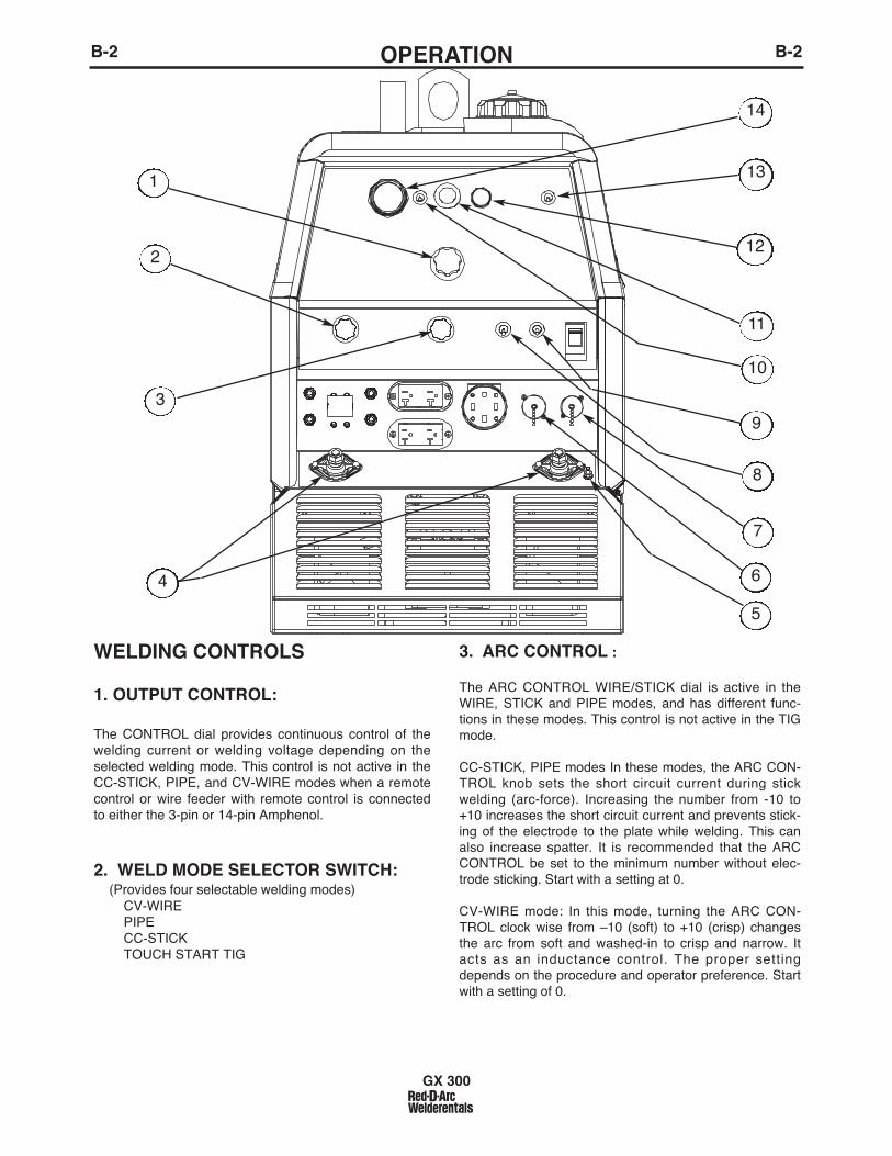
WELDING CONTROLS
1. OUTPUT CONTROL:
The CONTROL dial provides continuous control of thewelding current or welding voltage depending on theselected welding mode. This control is not active in theCC-STICK, PIPE, and CV-WIRE modes when a remotecontrol or wire feeder with remote control is connectedto either the 3-pin or 14-pin Amphenol.
2. WELD MODE SELECTOR SWITCH:(Provides four selectable welding modes)
CV-WIREPIPECC-STICKTOUCH START TIG
3. ARC CONTROL :
The ARC CONTROL WIRE/STICK dial is active in theWIRE, STICK and PIPE modes, and has different func-tions in these modes. This control is not active in the TIGmode.
CC-STICK, PIPE modes In these modes, the ARC CON-TROL knob sets the short circuit current during stickwelding (arc-force). Increasing the number from -10 to+10 increases the short circuit current and prevents stick-ing of the electrode to the plate while welding. This canalso increase spatter. It is recommended that the ARCCONTROL be set to the minimum number without elec-trode sticking. Start with a setting at 0.
CV-WIRE mode: In this mode, turning the ARC CON-TROL clock wise from –10 (soft) to +10 (crisp) changesthe arc from soft and washed-in to crisp and narrow. Itacts as an inductance control. The proper settingdepends on the procedure and operator preference. Startwith a setting of 0.
GX 300
1
9
6
3
8
4
7
10
11
12
5
14
13
2
B-3OPERATIONB-3
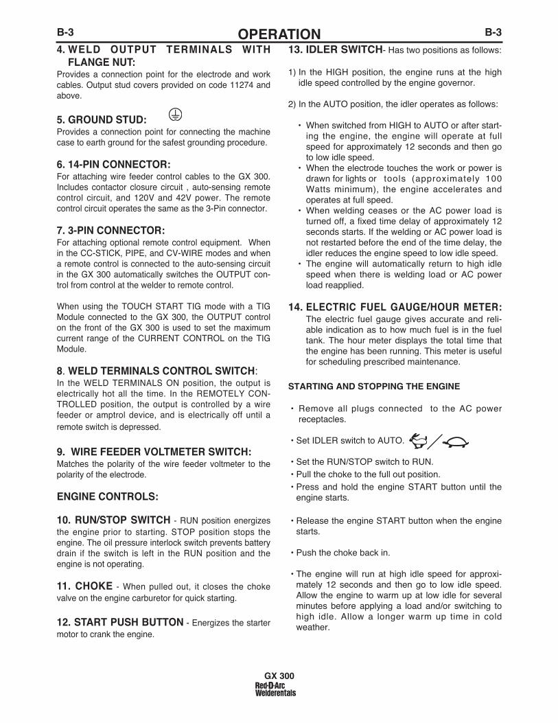
4. WELD OUTPUT TERMINALS WITHFLANGE NUT:
Provides a connection point for the electrode and workcables. Output stud covers provided on code 11274 andabove.
5. GROUND STUD: Provides a connection point for connecting the machinecase to earth ground for the safest grounding procedure.
6. 14-PIN CONNECTOR:For attaching wire feeder control cables to the GX 300.Includes contactor closure circuit , auto-sensing remotecontrol circuit, and 120V and 42V power. The remotecontrol circuit operates the same as the 3-Pin connector.
7. 3-PIN CONNECTOR:For attaching optional remote control equipment. Whenin the CC-STICK, PIPE, and CV-WIRE modes and whena remote control is connected to the auto-sensing circuitin the GX 300 automatically switches the OUTPUT con-trol from control at the welder to remote control.
When using the TOUCH START TIG mode with a TIGModule connected to the GX 300, the OUTPUT controlon the front of the GX 300 is used to set the maximumcurrent range of the CURRENT CONTROL on the TIGModule.
8. WELD TERMINALS CONTROL SWITCH:In the WELD TERMINALS ON position, the output iselectrically hot all the time. In the REMOTELY CON-TROLLED position, the output is controlled by a wirefeeder or amptrol device, and is electrically off until aremote switch is depressed.
9. WIRE FEEDER VOLTMETER SWITCH:Matches the polarity of the wire feeder voltmeter to thepolarity of the electrode.
ENGINE CONTROLS:
10. RUN/STOP SWITCH - RUN position energizesthe engine prior to starting. STOP position stops theengine. The oil pressure interlock switch prevents batterydrain if the switch is left in the RUN position and theengine is not operating.
11. CHOKE - When pulled out, it closes the chokevalve on the engine carburetor for quick starting.
12. START PUSH BUTTON - Energizes the startermotor to crank the engine.
13. IDLER SWITCH- Has two positions as follows:
1) In the HIGH position, the engine runs at the highidle speed controlled by the engine governor.
2) In the AUTO position, the idler operates as follows:
• When switched from HIGH to AUTO or after start-ing the engine, the engine will operate at fullspeed for approximately 12 seconds and then goto low idle speed.
• When the electrode touches the work or power isdrawn for lights or tools (approximately 100Watts minimum), the engine accelerates andoperates at full speed.
• When welding ceases or the AC power load isturned off, a fixed time delay of approximately 12seconds starts. If the welding or AC power load isnot restarted before the end of the time delay, theidler reduces the engine speed to low idle speed.
• The engine will automatically return to high idlespeed when there is welding load or AC powerload reapplied.
14. ELECTRIC FUEL GAUGE/HOUR METER:The electric fuel gauge gives accurate and reli-able indication as to how much fuel is in the fueltank. The hour meter displays the total time thatthe engine has been running. This meter is usefulfor scheduling prescribed maintenance.
STARTING AND STOPPING THE ENGINE
• Remove all plugs connected to the AC powerreceptacles.
• Set IDLER switch to AUTO.
• Set the RUN/STOP switch to RUN.• Pull the choke to the full out position.• Press and hold the engine START button until the
engine starts.
• Release the engine START button when the enginestarts.
• Push the choke back in.
• The engine will run at high idle speed for approxi-mately 12 seconds and then go to low idle speed.Allow the engine to warm up at low idle for severalminutes before applying a load and/or switching tohigh idle. Allow a longer warm up time in coldweather.
GX 300
B-4OPERATIONB-4
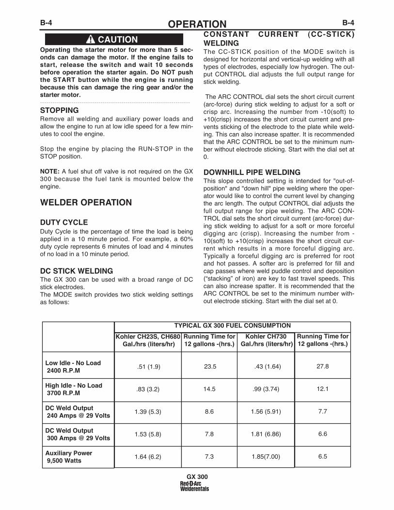
Operating the starter motor for more than 5 sec-onds can damage the motor. If the engine fails tostart, release the switch and wait 10 secondsbefore operation the starter again. Do NOT pushthe START button while the engine is runningbecause this can damage the ring gear and/or thestarter motor.------------------------------------------------------------------------STOPPINGRemove all welding and auxiliary power loads andallow the engine to run at low idle speed for a few min-utes to cool the engine.
Stop the engine by placing the RUN-STOP in theSTOP position.
NOTE: A fuel shut off valve is not required on the GX300 because the fuel tank is mounted below theengine.
WELDER OPERATION
DUTY CYCLEDuty Cycle is the percentage of time the load is beingapplied in a 10 minute period. For example, a 60%duty cycle represents 6 minutes of load and 4 minutesof no load in a 10 minute period.
DC STICK WELDINGThe GX 300 can be used with a broad range of DCstick electrodes. The MODE switch provides two stick welding settingsas follows:
CONSTANT CURRENT (CC-STICK)WELDINGThe CC-STICK position of the MODE switch isdesigned for horizontal and vertical-up welding with alltypes of electrodes, especially low hydrogen. The out-put CONTROL dial adjusts the full output range forstick welding.
The ARC CONTROL dial sets the short circuit current(arc-force) during stick welding to adjust for a soft orcrisp arc. Increasing the number from -10(soft) to+10(crisp) increases the short circuit current and pre-vents sticking of the electrode to the plate while weld-ing. This can also increase spatter. It is recommendedthat the ARC CONTROL be set to the minimum num-ber without electrode sticking. Start with the dial set at0.
DOWNHILL PIPE WELDINGThis slope controlled setting is intended for "out-of-position" and "down hill" pipe welding where the oper-ator would like to control the current level by changingthe arc length. The output CONTROL dial adjusts thefull output range for pipe welding. The ARC CON-TROL dial sets the short circuit current (arc-force) dur-ing stick welding to adjust for a soft or more forcefuldigging arc (crisp). Increasing the number from -10(soft) to +10(crisp) increases the short circuit cur-rent which results in a more forceful digging arc.Typically a forceful digging arc is preferred for rootand hot passes. A softer arc is preferred for fill andcap passes where weld puddle control and deposition(“stacking” of iron) are key to fast travel speeds. Thiscan also increase spatter. It is recommended that theARC CONTROL be set to the minimum number with-out electrode sticking. Start with the dial set at 0.
GX 300
CAUTION
Low Idle - No Load2400 R.P.M
High Idle - No Load3700 R.P.M
DC Weld Output240 Amps @ 29 Volts
DC Weld Output300 Amps @ 29 Volts
Auxiliary Power9,500 Watts
Kohler CH23S, CH680Gal./hrs (liters/hr)
.51 (1.9)
.83 (3.2)
1.39 (5.3)
1.53 (5.8)
1.64 (6.2)
Running Time for12 gallons -(hrs.)
23.5
14.5
8.6
7.8
7.3
Kohler CH730Gal./hrs (liters/hr)
.43 (1.64)
.99 (3.74)
1.56 (5.91)
1.81 (6.86)
1.85(7.00)
Running Time for12 gallons -(hrs.)
27.8
12.1
7.7
6.6
6.5
TYPICAL GX 300 FUEL CONSUMPTION

(1) When used with argon gas. The current ranges shown must be reduced when using argon/helium or pure helium shielding gases.(2) Tungsten electrodes are classified as follows by the American Welding Society (AWS):
Pure EWP1% Thoriated EWTh-12% Thoriated EWTh-2
Though not yet recognized by the AWS, Ceriated Tungsten is now widely accepted as a substitute for 2% Thoriated Tungsten in AC and DC applications.(3) DCEP is not commonly used in these sizes.(4) TIG torch nozzle "sizes" are in multiples of 1/16ths of an inch:
# 4 = 1/4 in. (6 mm)# 5 = 5/16 in. (8 mm)# 6 = 3/8 in. (10 mm)# 7 = 7/16 in. (11 mm)# 8 = _ in. (12.5 mm)#10 = 5/8 in. (16 mm)
(5) TIG torch nozzles are typically made from alumina ceramic. Special applications may require lava nozzles, which are less prone to breakage, but cannot withstand high temperaturesand high duty cycles.
B-5OPERATIONB-5
TIG WELDINGThe TOUCH START TIG setting of the MODE switch is for DCTIG (Tungsten Inert Gas) welding. To initiate a weld, the CON-TROL dial is first set to the desired current and the tungsten istouched to the work. During the time the tungsten is touching thework there is very little voltage or current and, in general, notungsten contamination. Then, the tungsten is gently lifted off thework in a rocking motion, which establishes the arc.
When in the TOUCH START TIG mode and when a Amptrol isconnected to the 6-Pin connector the OUTPUT dial is used to setthe maximum current range of the current control of the Amptrol.
The ARC CONTROL is not active in the TIG mode. To STOP aweld, simply pull the TIG torch away from the work. When thearc voltage reaches approximately 30 Volts the arc will go outand the machine will reset the current to the Touch Start level.To reinitiate the arc, retouch the tungsten to the work and lift.Alternatively, the weld can be stopped by releasing the Amptrolor arc start switch.
The GX-300 can be used in a wide variety of DC TIG weldingapplications. In general the ʻTouch Startʼ feature allows contami-nation free starting without the use of a Hi-frequency unit. Ifdesired, the K930-2 TIG Module can be used with the GX-300.The settings are for reference.
GX-300 settings when using the K930-2 TIG Module with anAmptrol or Arc Start Switch:
• Set the MODE Switch to the TOUCH START TIG setting.
• Set the "IDLER" Switch to the "AUTO" position.
• Set the "WELDING TERMINALS" switch to the "REMOTELYCONTROLLED" position. This will keep the "Solid State" con-tactor open and provide a "cold" electrode until the Amptrol orArc Start Switch is pressed.
When using the TIG Module, the OUTPUT control on the GX-300 is used to set the maximum range of the CURRENT CON-TROL on the TIG Module or an Amptrol if connected to the TIGModule.
WIRE WELDING-CVConnect a wire feeder to the GX-300 according to the instruc-tions in INSTALLATION INSTRUCTIONS Section.The GX-300 in the CV-WIRE mode, permits it to be used with abroad range of flux cored wire (Innershield and Outershield)electrodes and solid wires for MIG welding (gas metal arc weld-ing). Welding can be finely tuned using the ARC CONTROL.Turning the ARC CONTROL clockwise from –10 (soft) to +10(crisp) changes the arc from soft and washed-in to crisp and nar-row. It acts as an inductance/pinch control. The proper settingdepends on the procedure and operator preference. Start withthe dial set at 0.
Listed below are some wires suitable for use on this machine: • Innershield - NR-311, NS-3M, NR-207, NR-203 Ni 1%,
NR-212.• Outershield - 0S-70, 0S-71M, 0S-71 ELITE.• Solid wires for MIG welding - .035 (0.9 mm), and .045 (1.1 mm), Super Arc L-50 and L-56, .035 (0.9 mm) and .045 (1.1 mm) Blue Max MIG 308 LS.
Contact your local authorized Lincoln Electric Distributor or theLincoln Electric Company for specific wires used on certainapplications with this machine.
GX 300
TYPICAL CURRENT RANGES (1) FOR TUNGSTEN ELECTRODES(2)
Tungsten Electrode DCEN (-) DCEP (+) Approximate Argon Gas Flow TIG TORCH
Diameter in. (mm) Flow Rate C.F.H. ( l /min.) Nozzle Size (4), (5)
1%, 2% Thoriated 1%, 2% Thoriated Aluminum Stainless SteelTungsten Tungsten
.010 (.25) 2-15 (3) 3-8 (2-4) 3-8 (2-4) #4, #5, #60.020 (.50) 5-20 (3) 5-10 (3-5) 5-10 (3-5)0.040 (1.0) 15-80 (3) 5-10 (3-5) 5-10 (3-5)
1/16 (1.6) 70-150 10-20 5-10 (3-5) 9-13 (4-6) #5, #6
3/32 (2.4) 150-250 15-30 13-17 (6-8) 11-15 (5-7) #6, #7, #81/8 (3.2) 250-400 25-40 15-23 (7-11) 11-15 (5-7)
5/32 (4.0) 400-500 40-55 21-25 (10-12) 13-17 (6-8) #8, #103/16 (4.8) 500-750 55-80 23-27 (11-13) 18-22 (8-10)1/4 (6.4) 750-1000 80-125 28-32 (13-15) 23-27 (11-13)

Permissible Current in
@120 VAC *80**60**46**36200
B-6OPERATIONB-6
ARC GOUGINGThe GX 300 can be used for limited arc gouging. Foroptimal performance, set the MODE switch to CC-STICK and the ARC CONTROL to +10.
Set the CONTROL knob to adjust output current to thedesired level for the gouging electrode being usedaccording to the ratings in the following table.
Carbon Diameter Current Range (DC, electrodepositive)
1/8" 60-90 Amps
5/32" 90-150 Amps
3/16" 200-250 AmpsAUXILIARY POWER:If a GFCI receptacle is tripped, See the MAINTE-NANCE section for detailed information on testing andresetting the GFCI receptacle.
Start the engine and set the IDLER control switch to thedesired operating mode. Full power is available regardlessof the welding control settings providing no welding currentis being drawn.
The auxiliary power of the GX 300 consists of two 20 Amp-120 VAC (5-20R) duplex GFCI receptacles and one 50 Amp120/240 VAC (14-50R) receptacle. The 240 VAC receptaclecan be split for single phase 120 VAC operation.
The auxiliary power capacity is 10,000 watts Peak,9500 Watts continuous of 60 Hz, single phase power.The auxiliary power capacity rating in watts is equiva-lent to volt-amperes at unity power factor. The maxpermissible current of the 240 VAC output is 40 Amps. The 240 VAC output can be split to provide two sepa-rate 120 VAC outputs with a max permissible currentof 40 Amps per output to two separate 120 VACbranch circuits (these circuits cannot be paralleled).Output voltage is within ± 10% at all loads up to ratedcapacity. All auxiliary power is protected by circuitbreakers.
The 120 V auxiliary power receptacles should only beused with three wire grounded type plugs or approveddouble insulated tools with two wire plugs. The currentrating of any plug used with the system must be atleast equal to the current capacity of the associatedreceptacle.
NOTE: The 240 V receptacle has two circuits, each ofwhich measure 120 V to neutral but are of oppositepolarities and cannot be paralleled.
Simultaneous Welding and Auxiliary Power LoadsThe above auxiliary power ratings are with no weldingload. Simultaneous welding and power loads arespecified in the following table. The permissible cur-rents shown assume that current is being drawn fromeither the 120 VAC or 240 VAC supply (not both at thesame time).
GX 300
WeldingOutput-Amps
0100150200250300
Permissible Power-Watts
(Unity Power Factor)
95007100560042002300
0
Auxiliary-Amps
@ 240 VAC 40302318100
* Each duplex receptacle is limited to 20 amps.** Not to exceed 40A per 120 VAC branch circuit when splitting the 240 VAC output.
GX 300 Simultaneous Welding and Power Loads
GX 300 Extension Cord Length Recommendations(Use the shortest length extension cord possible sized per the following table.)
Current(Amps)
1520152040
VoltageVolts120120240240240
Load(Watts)18002400360048009500
30
60
(9)
(18)
40307560
(12)(9)(23)(18)
755015010050
(23)(15)(46)(30)(15)
1258822517590
(38)(27)(69)(53)(27)
175138350275150
(53)(42)(107)(84)(46)
300225600450225
(91)(69)
(183)(137)(69)
Maximum Allowable Cord Length in ft. (m) for Conductor Size
Conductor size is based on maximum 2.0% voltage drop.
14 AWG 12 AWG 10 AWG 8 AWG 6 AWG 4 AWG

C-1ACCESSORIESC-1
OPTIONS/ACCESSORIES AND COM-PATIBLE LINCOLN EQUIPMENTK957-1 HEAVY DUTY, TWO WHEEL TRAILER FORSMALL WELDERSFor road, off-road and in-plant and yard towing.(For highway use, consult applicable federal, state andlocal laws regarding requirements for brakes, lights,fenders, etc.).Order:
K957-1 TrailerK958-1 Ball HitchK958-2 Lunette Eye HitchK959-2 Fender & Light KitK965-1 Cable Storage Rack
K1737-1 FOUR WHEEL ALL-TERRAIN UNDERCAR-RIAGE For moving by hand at construction sites.Heavy duty puncture resistant pneumatic tires.
K1770-1 UNDERCARRIAGE (FACTORY)For moving by hand on a smooth surface.Heavy duty puncture resistant pneumatic tires & frontcaster, One or two gas cylinders can be mounted onthe rear of the undercarriage with the installation ofK1745-1 Cylinder Holder(s).
K1739-1 CABLE CARRIER KITFor use on K1737-1 and K1770-1 Undercarriages.
K1745-1 SINGLE GAS CYLINDER HOLDERFor use on K1770-1 Undercarriage. One or two may beinstalled on an undercarriage.
K1788-1 ROLL CAGE - Gives added damage protection.
K886-2 CANVAS COVER - Protects machine when not in use.
K1898-1 SPARK ARRESTORMounts inside exhaust pipe.
K704 ACCESSORY SET - Includes 35 ft. (10m) ofelectrode cable and 30 ft. (9.1m) of work cable, head-shield, work clamp electrode holder. Cables are ratedat 400 amps, 100% duty cycle.
K802-N POWER PLUG KITProvides four 120 volt plugs rated at 20 amps eachand one dual voltage, full KVA plug rated at 120/240volts, 50 amps.
K802-R POWER PLUG KITProvides four 120 volt plugs rated at 15 amps eachand one dual voltage, full KVA plug rated at 120/240volts, 50 amps.
T12153-9 50 AMP, 120/240 V POWER PLUG
K1816-1 FULL KVA ADAPTER KITPlugs into the 120/240V NEMA 14-50R receptacle onthe case front (which accepts 4-prong plugs) andconverts it to a NEMA 6-50R receptacle, (whichaccepts 3-prong plugs.)
GX 300

D-1MAINTENANCED-1
GX 300
KOHLER ENGINE
(1) Service more frequently when used in dusty areas and/or at high ambienttemperatures.
SAFETY PRECAUTIONS
• Have qualified personnel do all maintenanceand troubleshooting work.
• Turn the engine off before working inside themachine or servicing the engine.
• Remove guards only when necessary toperform maintenance and replace them whenthe maintenance requiring their removal iscomplete. If guards are missing from themachine, obtain replacements from a LincolnDistributor. (See Operating Manual Parts List.)
Read the Safety Precautions in the front of thismanual and in the Engine Ownerʼs Manual beforeworking on this machine.
Keep all equipment safety guards, covers, anddevices in position and in good repair. Keep hands,hair, clothing, and tools away from the gears, fans,and all other moving parts when starting, operating, orrepairing the equipment.
Routine Maintenance
At the end of each dayʼs use, refill the fuel tank tominimize moisture condensation in the tank. Runningout of fuel tends to draw dirt into the fuel system.Also, check the crankcase oil level and add oil ifindicated.
FREQUENCYDaily or BeforeStarting Engine
5 Hours
Every 25 Hours
Every 100 HoursEvery 100 HoursEvery 100 Hours
Every 100 HoursEvery 200 HoursEvery 200 HoursEvery 2 Years
MAINTENANCE REQUIRED• Fill fuel tank.• Check oil level.• Check air cleaner for dirty, loose,
or damaged parts.• Check air intake and cooling
areas, clean as necessary.First Oil Change
• Service air pre-cleaner..
• Change engine oil. (1)
• Replace fuel filter element.• Clean or replace air filter ele-ment. (1)
• Spark Plug Arrester • Replace oil filter. (1)
• Check spark plug and gap• Check fuel lines and clamps.
WARNING
ITEM KOHLER CH23S, CH680 ENGINE
Oil Filter Kohler 12 050 01, Fram PH8172*
Air Filter Element Kohler 47 083 03, Fram CA79
Air Filter Pre-Cleaner Kohler 24 083 02
Fuel Filter Kohler 24 050 13
Spark Plug Champion RC12YC (.030" Gap)
Battery ci Group 58 (435 CCA)
ENGINE MAINTENANCE COMPONENTSMAKE AND PART NUMBER
KOHLER CH730 ENGINE
Kohler 12 050 01, Fram PH8172*
Kohler 24 083 03
Kohler 24 083 05
Kohler 24 050 13
Champion RC12YC (.030" Gap)
ci Group 58 (435 CCA)
* Oil capacity increases from 2.0 Qts. to 2.1 Qts. when using this filter.

D-2MAINTENANCED-2
Engine Oil ChangeDrain the oil while the engine is warm to assure rapidand complete draining.
• Remove the oil filler cap and dipstick. Remove theyellow cap from the oil drain valve and attach theflexible drain tube supplied with the machine. Pushin and twist the drain valve counterclockwise. Pullthe valve out and drain the oil into a suitablecontainer.
• Close the drain valve by pushing in and twistingclockwise. Replace the yellow cap.
• Refill to the upper limit mark on the dipstick with therecommended oil. Tighten the oil filler cap securely.
Engine Oil Refill CapacitiesWithout oil filter replacement:• 1.7 US qt. (1.4 Imp qt., 1.6 liter)-Kohler
With oil filter replacement:• 2.0 US qt. (1.7 Imp qt., 1.9 liter)-Kohler
Use 4-stroke motor oil that meets or exceeds therequirements for API service classification SG or SH.Always check the API SERVICE label on the oil con-tainer to be sure it includes the letters SG or SH.SAE 10W-30 is recommended for general, all-temper-ature use, -5° F to 104° F (-20° C to 40° C). For theOnan engine, it is recommended that SAE 30 oil beused above 82° F (27° C). See Engine Ownerʼs Manual for more specific infor-mation on oil viscosity recommendations.Wash your hands with soap and water after handlingused oil.Please dispose of used motor oil in a manner that iscompatible with the environment. We suggest youtake it in a sealed container to your local service sta-tion or recycling center for reclamation. Do not throwit in the trash, pour it on the ground or down a drain.
Oil Filter Change• Drain the engine oil.
• Remove the oil filter, and drain the oil into a suitablecontainer. Discard the used oil filter.
• Clean the filter mounting base, and coat the gasketof the new oil filter with clean engine oil.
• Screw on the new oil filter by hand, until the gasketcontacts the filter mounting base, then use an oil fil-ter socket tool to tighten the filter an additional 1/2 to7/8 turn.
• Refill the crankcase with the specified amount of therecommended oil. Reinstall the oil filler cap.
• Start the engine and check for oil filter leaks.
• Stop the engine, and check the oil level. If neces-sary, add oil to the upper limit mark on the dipstick.
Air Cleaner ServiceA dirty air cleaner will restrict air flow to the carbure-tor. To prevent carburetor malfunction, service the aircleaner regularly. Service more frequently when oper-ating the engine in extremely dusty areas.
Never use gasoline or low flash point solvents forcleaning the air cleaner element. A fire or explo-sion could result.
Never run the engine without the air cleaner.Rapid engine wear will result from contaminants,such as dust and dirt being drawn into the engine.
Air Pre-cleaner Service
• Loosen the cover retaining knob and remove thecover.
• Remove the pre-cleaner from the paper element.
• Wash the pre-cleaner in warm water with detergent.Rinse the pre-cleaner thoroughly until all traces ofdetergent are eliminated. Squeeze out excess water(do not wring). Allow the pre-cleaner to air dry.
• Saturate the pre-cleaner with new engine oil.Squeeze out all excess oil.
• Reinstall the pre-cleaner over the paper element.
• Reinstall the air cleaner cover. Secure cover withthe cover retaining knob.
GX 300
CAUTION
WARNING
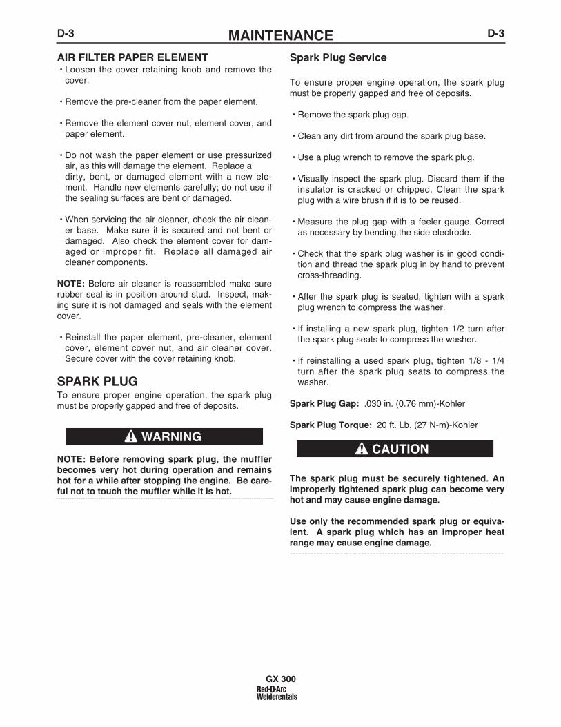
D-3MAINTENANCED-3
AIR FILTER PAPER ELEMENT• Loosen the cover retaining knob and remove the
cover.
• Remove the pre-cleaner from the paper element.
• Remove the element cover nut, element cover, andpaper element.
• Do not wash the paper element or use pressurizedair, as this will damage the element. Replace a dirty, bent, or damaged element with a new ele-ment. Handle new elements carefully; do not use ifthe sealing surfaces are bent or damaged.
• When servicing the air cleaner, check the air clean-er base. Make sure it is secured and not bent ordamaged. Also check the element cover for dam-aged or improper fit. Replace all damaged aircleaner components.
NOTE: Before air cleaner is reassembled make surerubber seal is in position around stud. Inspect, mak-ing sure it is not damaged and seals with the elementcover.
• Reinstall the paper element, pre-cleaner, elementcover, element cover nut, and air cleaner cover.Secure cover with the cover retaining knob.
SPARK PLUGTo ensure proper engine operation, the spark plugmust be properly gapped and free of deposits.
NOTE: Before removing spark plug, the mufflerbecomes very hot during operation and remainshot for a while after stopping the engine. Be care-ful not to touch the muffler while it is hot.
Spark Plug Service
To ensure proper engine operation, the spark plugmust be properly gapped and free of deposits.
• Remove the spark plug cap.
• Clean any dirt from around the spark plug base.
• Use a plug wrench to remove the spark plug.
• Visually inspect the spark plug. Discard them if theinsulator is cracked or chipped. Clean the sparkplug with a wire brush if it is to be reused.
• Measure the plug gap with a feeler gauge. Correctas necessary by bending the side electrode.
• Check that the spark plug washer is in good condi-tion and thread the spark plug in by hand to preventcross-threading.
• After the spark plug is seated, tighten with a sparkplug wrench to compress the washer.
• If installing a new spark plug, tighten 1/2 turn afterthe spark plug seats to compress the washer.
• If reinstalling a used spark plug, tighten 1/8 - 1/4turn after the spark plug seats to compress thewasher.
Spark Plug Gap: .030 in. (0.76 mm)-Kohler
Spark Plug Torque: 20 ft. Lb. (27 N-m)-Kohler
The spark plug must be securely tightened. Animproperly tightened spark plug can become veryhot and may cause engine damage.
Use only the recommended spark plug or equiva-lent. A spark plug which has an improper heatrange may cause engine damage.------------------------------------------------------------------------
GX 300
WARNINGCAUTION

D-4MAINTENANCED-4
FUEL FILTER• Check the fuel filter for water accumulation or sedi-
ment.
• Replace the fuel filter if it is found with excessivewater accumulation or sediment.
ENGINE ADJUSTMENT
Adjustments to the engine are to be made only by aLincoln Service Center or an authorized Field ServiceShop.
BATTERY MAINTENANCETo access the battery, Remove the 2 screws from therear battery tray using a screwdriver or a 3/8" socket.Slide the battery tray out only far enough to accessthe battery terminals.
GASES FROM BATTERY can explode.Keep sparks, flame and cigarettesaway from battery.
To prevent EXPLOSION when:
INSTALLING A NEW BATTERY — disconnectnegative cable from old battery first and con-nect to new battery last.
CONNECTING A BATTERY CHARGER —remove battery from welder by disconnectingnegative cable first, then positive cable andbattery clamp. When reinstalling, connectnegative cable last. Keep well ventilated.
USING A BOOSTER — connect positive lead tobattery first then connect negative lead to neg-ative battery lead at engine foot.
BATTERY ACID can burn eyes and skin.
Wear gloves and eye protectionand be careful when working nearbattery.
Follow instructions printed on bat-tery.
GX 300
OVERSPEED IS HAZARDOUSThe maximum allowable high idle speed for thismachine is 3750 RPM, no load. Do NOT tamperwith governor components or setting or make anyother adjustments to increase the maximumspeed. Severe personal injury and damage to themachine can result if operated at speeds abovemaximum.
CLEANING THE BATTERYKeep the battery clean by wiping it with a damp clothwhen dirty. If the terminals appear corroded, discon-nect the battery cables and wash the terminals with anammonia solution or a solution of 1/4 pound (0.1113kg) of baking soda and 1 quart (0.9461Ltrs.) of water.Be sure the battery vent plugs (if equipped) are tightso that none of the solution enters the cells.
After cleaning, flush the outside of the battery, the bat-tery compartment, and surrounding areas with clearwater. Coat the battery terminals lightly with petroleumjelly or a non-conductive grease to retard corrosion.Keep the battery clean and dry. Moisture accumula-tion on the battery can lead to more rapid dischargeand early battery failure.
CHECKING THE ELECTROLYTE LEVEL
If battery cells are low, fill them to the neck of the fillerhole with distilled water and recharge. If one cell islow, check for leaks.
CHARGING THE BATTERYWhen you charge, jump, replace, or otherwise con-nect battery cables to the battery, be sure the polarityis correct. Improper polarity can damage the chargingcircuit. The GX 300 positive (+) battery terminal has ared terminal cover.
If you need to charge the battery with an externalcharger, disconnect the negative cable first, then thepositive cable before you attach the charger leads.After the battery is charged, reconnect the positivebattery cable first and the negative cable last. Failureto do so can result in damage to the internal chargercomponents.Follow the instructions of the battery charger manu-facturer for proper charger settings and charging time.
SERVICING OPTIONAL SPARKARRESTOR
Clean every 100 hours.
• MUFFLER MAY BE HOT
• ALLOW ENGINE TO COOL BEFORE INSTALLINGTHE SPARK ARRESTER!
• DO NOT OPERATE ENGINE WHILE INSTALLINGTHE SPARK ARRESTER!
WARNING
WARNING

D-5MAINTENANCED-5
GX 300
Welder/Generator Maintenance
STORAGE: Store the GX 300 in clean, dry protectedareas.
CLEANING: Blow out the generator and controls peri-odically with low pressure air. Do this at least once aweek in particularly dirty areas.
BRUSH REMOVAL AND REPLACEMENT: Itʼs nor-mal for the brushes and slip rings to wear and darkenslightly. Inspect the brushes when a generator over-haul is necessary.
Do not attempt to polish slip rings while theengine is running.
Service and Repair should only be performed byLincoln Electric Factory Trained Personnel.Unauthorized repairs performed on this equip-ment may result in danger to the technician andmachine operator and will invalidate your factorywarranty. For your safety and to avoid ElectricalShock, please observe all safety notes and pre-cautions.
WARNING
CAUTION
GFCI RECEPTACLE TESTING AND RESET-TING PROCEDURE
The GFCI receptacle should be properly tested atleast once every month or whenever it is tripped. Toproperly test and reset the GFCI receptacle:
• If the receptacle has tripped, first carefully removeany load and check it for damage.
• If the equipment has been shut down, it must berestarted.
• The equipment needs to be operating at high idlespeed and any necessary adjustments made on thecontrol panel so that the equipment is providing atleast 80 volts to the receptacle input terminals.
• The circuit breaker for this receptacle must not betripped. Reset if necessary.
• Push the "Reset" button located on the GFCI recep-tacle. This will assure normal GFCI operation.
• Plug a night-light (with an "ON/OFF" switch) or otherproduct (such as a lamp) into the GFCI receptacleand turn the product "ON".
• Push the "Test" button located on the GFCI recepta-cle. The night-light or other product should go"OFF".
• Push the "Reset" button, again. The light or otherproduct should go "ON" again.
If the light or other product remains "ON" when the"Test" button is pushed, the GFCI is not working prop-erly or has been incorrectly installed (miswired). Ifyour GFCI is not working properly, contact a qualified,certified electrician who can assess the situation,rewire the GFCI if necessary or replace the device.

E-1TROUBLESHOOTINGE-1
GX 300
If for any reason you do not understand the test procedures or are unable to perform the tests/repairs safely, contact yourLocal Authorized Field Service Facility for technical troubleshooting assistance before you proceed.
CAUTION
This Troubleshooting Guide is provided to help youlocate and repair possible machine malfunctions.Simply follow the three-step procedure listed below.
Step 1. LOCATE PROBLEM (SYMPTOM).Look under the column labeled “PROBLEM (SYMP-TOMS)”. This column describes possible symptomsthat the machine may exhibit. Find the listing thatbest describes the symptom that the machine isexhibiting.
Step 2. POSSIBLE CAUSE.The second column labeled “POSSIBLE CAUSE” liststhe obvious external possibilities that may contributeto the machine symptom.
Step 3. RECOMMENDED COURSE OF ACTIONThis column provides a course of action for thePossible Cause, generally it states to contact yourlocal Field Service Facility.
If you do not understand or are unable to perform theRecommended Course of Action safely, contact yourlocal Field Service Facility.
HOW TO USE TROUBLESHOOTING GUIDE
Service and Repair should only be performed by Trained Personnel. Unauthorized repairs performedon this equipment may result in danger to the technician and machine operator and will invalidateyour factory warranty. For your safety and to avoid Electrical Shock, please observe all safety notesand precautions detailed throughout this manual.
__________________________________________________________________________
WARNING

E-2TROUBLESHOOTINGE-2
GX 300
Observe all Safety Guidelines detailed throughout this manual
If for any reason you do not understand the test procedures or are unable to perform the tests/repairs safely, contact yourLocal Authorized Field Service Facility for technical troubleshooting assistance before you proceed.
CAUTION
PROBLEMS(SYMPTOMS)
POSSIBLE CAUSE
RECOMMENDEDCOURSE OF ACTION
Major Physical or Electrical Damageis Evident.
Engine will not "crank".
Engine will "crank" but not start.
Engine shuts down shortly afterstarting.
Battery does not stay charged.
1. Contact your local AuthorizedField Service Facility.
1. Battery is low, Charge Battery.
2. Loose battery cable connections.Inspect, clean and tighten.
3. Faulty engine starter motor.
4. “Battery Circuit” circuit breaker istripped.
1. Out of fuel, Fill tank and bleed fuelsystem.
2. Faulty fuel solenoid or faulty PCboard or ignition system.
1. Low oil level, Change oil and oilfilter and fill to proper level. Startengine and look for leaks.
2. Faulty oil pressure switch or otherengine component.
3. Open rotor circuit.
1. Faulty battery, replace.
2. Loose connections at battery oralternator. Clean and tighten con-nections.
3. Faulty engine alternator or charg-er module.
If all recommended possible areasof misadjustment have beenchecked and the problem persists,Contact your local AuthorizedField Service Facility.
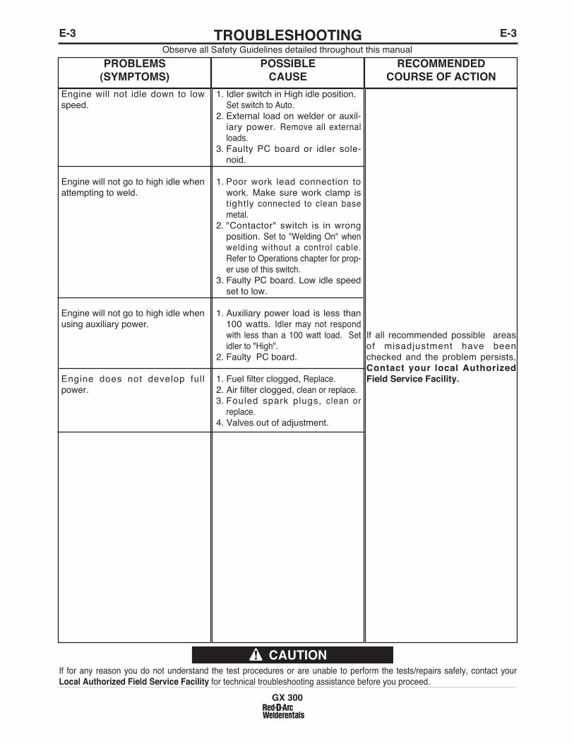
E-3TROUBLESHOOTINGE-3
GX 300
Observe all Safety Guidelines detailed throughout this manual
If for any reason you do not understand the test procedures or are unable to perform the tests/repairs safely, contact yourLocal Authorized Field Service Facility for technical troubleshooting assistance before you proceed.
CAUTION
PROBLEMS(SYMPTOMS)
POSSIBLE CAUSE
RECOMMENDEDCOURSE OF ACTION
Engine will not idle down to lowspeed.
Engine will not go to high idle whenattempting to weld.
Engine will not go to high idle whenusing auxiliary power.
Engine does not develop fullpower.
1. Idler switch in High idle position.Set switch to Auto.
2. External load on welder or auxil-iary power. Remove all externalloads.
3. Faulty PC board or idler sole-noid.
1. Poor work lead connection towork. Make sure work clamp istightly connected to clean basemetal.
2. "Contactor" switch is in wrongposition. Set to "Welding On" whenwelding without a control cable.Refer to Operations chapter for prop-er use of this switch.
3. Faulty PC board. Low idle speedset to low.
1. Auxiliary power load is less than100 watts. Idler may not respondwith less than a 100 watt load. Setidler to "High".
2. Faulty PC board.
1. Fuel filter clogged, Replace.2. Air filter clogged, clean or replace.3. Fouled spark plugs, clean or
replace.4. Valves out of adjustment.
If all recommended possible areasof misadjustment have beenchecked and the problem persists,Contact your local AuthorizedField Service Facility.

E-4TROUBLESHOOTINGE-4
GX 300
Observe all Safety Guidelines detailed throughout this manual
If for any reason you do not understand the test procedures or are unable to perform the tests/repairs safely, contact yourLocal Authorized Field Service Facility for technical troubleshooting assistance before you proceed.
CAUTION
PROBLEMS(SYMPTOMS)
POSSIBLE CAUSE
RECOMMENDEDCOURSE OF ACTION
No welding power output.
Welder has output but no control.
Wire feeder does not work whencontrol cable is connected to 14 pinAmphenol.
No auxiliary power.
1. Poor work lead connection towork. Make sure work clamp istightly connected to clean basemetal.
2. "Weld Terminals" switch in wrongposition. Place switch in "WeldTerminals On" position whenwelding without control cable.
3. Faulty PC board or welder alter-nator.
1. Poor remote/control cable con-nection to 3-pin or 14-pinAmphenol connector. Check con-nections.
2. Faulty remote cable or faulty wirefeeder or wire feeder cable.Replace if necessary.
3. Faulty control potentiometer orPC board.
1. Wire Feeder Power circuit break-er open. Check 42V and 120Vbeakers and reset if tripped.
2. Faulty control cable. Repair orreplace cable.
3. Faulty wire feeder.
1. GFCI Receptacle may havetripped. Follow “GFCIReceptacle Testing andResetting Procedure” in theMAINTENANCE section of thismanual.
2. Open circuit breakers. Resetbreakers. If breakers keep trip-ping, reduce power draw.
3. Faulty connections to auxiliaryreceptacles. Check connections.
4. GFCI tripped (if installed). Clearany ground fault and reset GFCIcircuit by pressing "Reset" buttonon the 120 V receptacle.
5. Faulty PC board or welder alter-nator.
If all recommended possible areasof misadjustment have beenchecked and the problem persists,Contact your local AuthorizedField Service Facility.

E-5TROUBLESHOOTINGE-5Observe all Safety Guidelines detailed throughout this manual
If for any reason you do not understand the test procedures or are unable to perform the tests/repairs safely, contact yourLocal Authorized Field Service Facility for technical troubleshooting assistance before you proceed.
CAUTION
PROBLEMS(SYMPTOMS)
POSSIBLE CAUSE
RECOMMENDEDCOURSE OF ACTION
The welding arc is “cold.” The weld-ing arc is not stable or is not satis-factory. The engine runs normally.The auxiliary power is normal.
1. Make sure the MODE selectorswitch is in the correct position forthe process being used. (Forexample, CV-WIRE, PIPE, CC-STICK.)
2. Make sure the electrode (wire,gas, voltage, current etc.) is cor-rect for the process being used.
3. Check for loose or faulty connec-tions at the weld output terminalsand welding cable connections.
4. The welding cables may be toolong or coiled, causing an exces-sive voltage drop.
If all recommended possible areas ofmisadjustment have been checkedand the problem persists, Contactyour local Authorized FieldService Facility.
GX 300

F-1DIAGRAMSF-1
GX 300

F-2DIAGRAMSF-2
GX 300

F-3DIAGRAMSF-3
or s
ervi
ce th
is e
quip
men
t.O
nly
qual
ified
per
sonn
el s
houl
d in
stal
l,use
Kee
p aw
ay fr
om m
ovin
g pa
rts.
Kee
p gu
ards
in p
lace
.M
OV
ING
PA
RT
S c
an in
jure
WAR
NIN
G
Do
not t
ouch
ele
ctric
ally
live
par
ts.
befo
re s
ervi
cing
.D
isco
nnec
t NE
GA
TIV
E (-
) Bat
tery
lead
Do
not o
pera
te w
ith p
anel
s op
en.
ELE
CT
RIC
SH
OC
K c
an k
ill
14 P
IN
AMPH
ENO
L
TO W
OR
K
+_
ENG
INE
WEL
DERS
/LN-
8 CO
NNEC
TIO
N DI
AGRA
M
S24
787-
6
4-14
-200
0
TO L
N-8
INPU
TCA
BLE
PLUG
ELEC
TRO
DE
CAB
LETO
WIR
E FE
ED U
NIT
CAU
TIO
N:
ANY
INC
REA
SE O
F TH
E H
IGH
IDLE
EN
GIN
E R
PM B
Y C
HAN
GIN
G T
HE
GO
VER
NO
R S
ETTI
NG
OR
OVE
RR
IDIN
G T
HE
THR
OTT
LE L
INKA
GE
WIL
L C
AUSE
AN IN
CR
EASE
IN T
HE
AC W
IRE
FEED
ER V
OLT
AGE,
WH
ICH
CAN
DAM
AGE
THE
CO
NTR
OL
CIR
CU
IT. T
HE
ENG
INE
GO
VER
NO
R S
ETTI
NG
IS P
RE-
SET
AT T
HE
FAC
TOR
Y –
DO
NO
T AD
JUST
ABO
VE R
PM S
PEC
IFIC
ATIO
NS
LIST
ED IN
TH
E EN
GIN
E W
ELD
ER O
PER
ATIN
G M
ANU
AL.
N.A
. W
ELD
ING
CAB
LES
MU
ST B
E O
F PR
OPE
R C
APAC
ITY
FOR
TH
E C
UR
REN
T AN
D D
UTY
CYC
LE O
F IM
MED
IATE
AN
D F
UTU
RE
A
PPLI
CAT
ION
S. S
EE O
PER
ATIN
G M
ANU
AL.
N.B
. C
ON
NEC
T W
ELD
ING
CAB
LES
TO O
UTP
UT
STU
DS
FOR
DES
IRED
PO
LAR
ITY.
PO
SITI
ON
TH
E W
IRE
FEED
ER V
OLT
MET
ER S
WIT
CH
TO
M
ATC
H T
HE
POLA
RIT
Y O
F TH
E EL
ECTR
OD
E C
ABLE
.N
.C.
PLA
CE
IDLE
R S
WIT
CH
IN “
HIG
H” P
OSI
TIO
N.
K595
CO
NTR
OL
CABL
E
GX 300

F-4DIAGRAMSF-4
GX 300

F-5DIAGRAMSF-5
GX 300

F-6DIAGRAMSF-6
GX 300
2
9/03
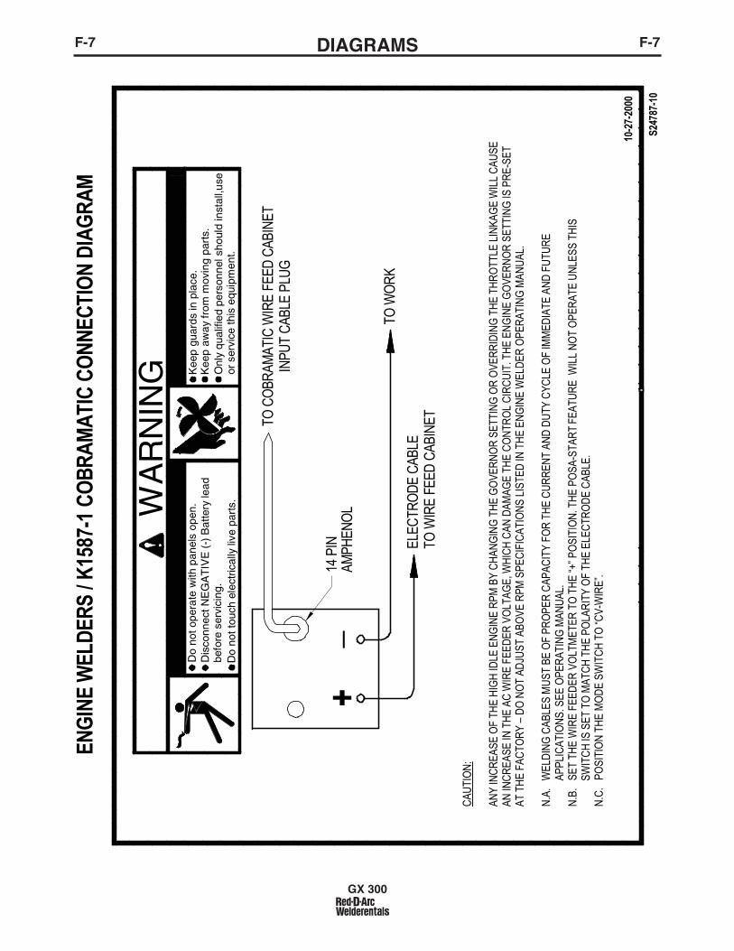
F-7DIAGRAMSF-7
GX 300

F-8DIAGRAMSF-8
NO
TE
:T
his
diag
ram
is fo
r re
fere
nce
only
. It
may
not
be
accu
rate
for
all m
achi
nes
cove
red
by th
is m
anua
l. T
he s
peci
fic d
iagr
am fo
r a
part
icul
ar c
ode
is p
aste
d in
side
the
mac
hine
on
one
of th
e en
clos
ure
pane
ls.
If th
e di
agra
m is
ille
gibl
e, w
rite
to th
e S
ervi
ce D
epar
tmen
t for
a r
epla
cem
ent.
Giv
e th
e eq
uipm
ent c
ode
num
ber.
GX 300

F-9DIMENSION PRINTF-9
GX 300
M22
449
A
CIRC
UIT
BREA
KERS
41.2
010
46.5
17.5
044
4.5
19.5
049
5.3
16.7
542
5.4
TRU
CK/U
ND
ERCA
RRIA
GE
MO
UN
TIN
G H
OLE
S
7.22
183.
324
.86
631.
32.
6266
.5
CEN
TER
OF
GRA
VITY
29.8
075
6.9
42.1
010
69.5
20.8
052
8.3
23.5
059
6.9
10.2
826
1.0
10.7
827
3.9
33.6
285
4.0
36.2
492
0.4
DIM
EN
SIO
N D
IAG
RA
M C
OD
ES
116
78, 1
1740
, 117
95, 1
1802
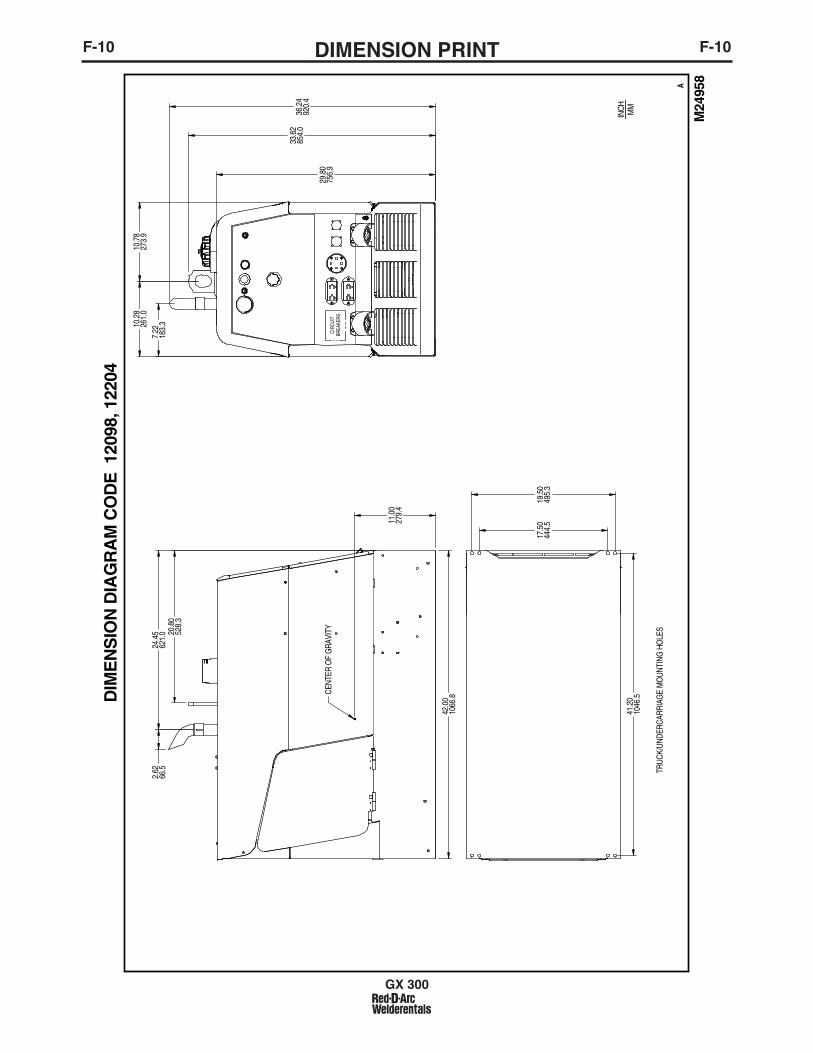
F-10DIMENSION PRINTF-10
GX 300
M24
958
A
CIRC
UIT
BREA
KERS
41.2
010
46.5
17.5
044
4.5
19.5
049
5.3
TRUC
K/UN
DERC
ARRI
AGE
MO
UNTI
NG H
OLE
S
7.22
183.
3
29.8
075
6.9
INCH MM
10.2
826
1.0
10.7
827
3.9
33.6
285
4.0
CEN
TER
OF
GRA
VITY
11.0
027
9.4
20.8
052
8.3
24.4
562
1.0
2.62
66.5
42.0
010
66.8
36.2
492
0.4
DIM
EN
SIO
N D
IAG
RA
M C
OD
E 1
2098
, 122
04

NOTES
GX 300

• Sales and Service through Subsidiaries and Distributors Worldwide •
Cleveland, Ohio 44117-1199 U.S.A. TEL: 216.481.8100 FAX: 216.486.1751 WEB SITE: www.lincolnelectric.com
• World's Leader in Welding and Cutting Products •