Embed Size (px)
Citation preview

RED-D-ARCES 275i
IM803November, 2002
Red-D-Arc Spec-Built Welding EquipmentThis RED-D-ARC welder is built to RED-D-ARC Extreme Dutydesign specifications by Lincoln Electric.
Safety Depends on YouThis welder is designed and built with safety in mind.However, your overall safety can be increased by proper installation ... and thoughtful operation on your part.DO NOT INSTALL, OPERATE OR REPAIR THIS EQUIPMENT WITHOUT READING THIS MANUAL AND THE SAFETY PRECAUTIONS CONTAINED THROUGHOUT.And, most importantly, think before you act and be careful.
For use with machines having Code Numbers: 10994
North America’s Largest Fleet of Welding Equipment
1-800-245-3660
OPERATOR’S MANUAL

FOR ENGINEpowered equipment.
1.a. Turn the engine off before troubleshooting and maintenancework unless the maintenance work requires it to be running.
____________________________________________________1.b. Operate engines in open, well-ventilated
areas or vent the engine exhaust fumes outdoors.
____________________________________________________1.c. Do not add the fuel near an open flame
welding arc or when the engine is running.Stop the engine and allow it to cool beforerefueling to prevent spilled fuel from vaporiz-ing on contact with hot engine parts andigniting. Do not spill fuel when filling tank. Iffuel is spilled, wipe it up and do not startengine until fumes have been eliminated.
____________________________________________________1.d. Keep all equipment safety guards, covers and devices in
position and in good repair.Keep hands, hair, clothing andtools away from V-belts, gears, fans and all other movingparts when starting, operating or repairing equipment.
____________________________________________________
1.e. In some cases it may be necessary to remove safetyguards to perform required maintenance. Removeguards only when necessary and replace them when themaintenance requiring their removal is complete.Always use the greatest care when working near movingparts.
___________________________________________________1.f. Do not put your hands near the engine fan.
Do not attempt to override the governor oridler by pushing on the throttle control rodswhile the engine is running.
___________________________________________________1.g. To prevent accidentally starting gasoline engines while
turning the engine or welding generator during maintenancework, disconnect the spark plug wires, distributor cap ormagneto wire as appropriate.
iSAFETYi
ARC WELDING CAN BE HAZARDOUS. PROTECT YOURSELF AND OTHERS FROM POSSIBLE SERIOUS INJURY OR DEATH.KEEP CHILDREN AWAY. PACEMAKER WEARERS SHOULD CONSULT WITH THEIR DOCTOR BEFORE OPERATING.
Read and understand the following safety highlights. For additional safety information, it is strongly recommended that youpurchase a copy of “Safety in Welding & Cutting - ANSI Standard Z49.1” from the American Welding Society, P.O. Box351040, Miami, Florida 33135 or CSA Standard W117.2-1974. A Free copy of “Arc Welding Safety” booklet E205 is availablefrom the Lincoln Electric Company, 22801 St. Clair Avenue, Cleveland, Ohio 44117-1199.
BE SURE THAT ALL INSTALLATION, OPERATION, MAINTENANCE AND REPAIR PROCEDURES AREPERFORMED ONLY BY QUALIFIED INDIVIDUALS.
WARNING
Mar ‘95
ELECTRIC AND MAGNETIC FIELDSmay be dangerous
2.a. Electric current flowing through any conductor causes localized Electric and Magnetic Fields (EMF). Welding current creates EMF fields around welding cables and welding machines
2.b. EMF fields may interfere with some pacemakers, andwelders having a pacemaker should consult their physicianbefore welding.
2.c. Exposure to EMF fields in welding may have other healtheffects which are now not known.
2.d. All welders should use the following procedures in order tominimize exposure to EMF fields from the welding circuit:
2.d.1. Route the electrode and work cables together - Securethem with tape when possible.
2.d.2. Never coil the electrode lead around your body.
2.d.3. Do not place your body between the electrode andwork cables. If the electrode cable is on your right side, the work cable should also be on your right side.
2.d.4. Connect the work cable to the workpiece as close aspossible to the area being welded.
2.d.5. Do not work next to welding power source.
1.h. To avoid scalding, do not remove theradiator pressure cap when the engine ishot.
CALIFORNIA PROPOSITION 65 WARNINGS
Diesel engine exhaust and some of its constituentsare known to the State of California to cause can-cer, birth defects, and other reproductive harm.
The engine exhaust from this product containschemicals known to the State of California to causecancer, birth defects, or other reproductive harm.
The Above For Diesel Engines The Above For Gasoline Engines
ES 275i

iiSAFETYii
ARC RAYS can burn.4.a. Use a shield with the proper filter and cover
plates to protect your eyes from sparks andthe rays of the arc when welding or observingopen arc welding. Headshield and filter lensshould conform to ANSI Z87. I standards.
4.b. Use suitable clothing made from durable flame-resistantmaterial to protect your skin and that of your helpers fromthe arc rays.
4.c. Protect other nearby personnel with suitable, non-flammablescreening and/or warn them not to watch the arc nor exposethemselves to the arc rays or to hot spatter or metal.
ELECTRIC SHOCK cankill.3.a. The electrode and work (or ground) circuits
are electrically “hot” when the welder is on.Do not touch these “hot” parts with your bareskin or wet clothing. Wear dry, hole-free
gloves to insulate hands.
3.b. Insulate yourself from work and ground using dry insulation.Make certain the insulation is large enough to cover your fullarea of physical contact with work and ground.
In addition to the normal safety precautions, if weldingmust be performed under electrically hazardousconditions (in damp locations or while wearing wetclothing; on metal structures such as floors, gratings orscaffolds; when in cramped positions such as sitting,kneeling or lying, if there is a high risk of unavoidable oraccidental contact with the workpiece or ground) usethe following equipment:
• Semiautomatic DC Constant Voltage (Wire) Welder.• DC Manual (Stick) Welder.• AC Welder with Reduced Voltage Control.
3.c. In semiautomatic or automatic wire welding, the electrode,electrode reel, welding head, nozzle or semiautomaticwelding gun are also electrically “hot”.
3.d. Always be sure the work cable makes a good electricalconnection with the metal being welded. The connectionshould be as close as possible to the area being welded.
3.e. Ground the work or metal to be welded to a good electrical(earth) ground.
3.f. Maintain the electrode holder, work clamp, welding cable andwelding machine in good, safe operating condition. Replacedamaged insulation.
3.g. Never dip the electrode in water for cooling.
3.h. Never simultaneously touch electrically “hot” parts ofelectrode holders connected to two welders because voltagebetween the two can be the total of the open circuit voltageof both welders.
3.i. When working above floor level, use a safety belt to protectyourself from a fall should you get a shock.
3.j. Also see Items 6.c. and 8.
FUMES AND GASEScan be dangerous.5.a. Welding may produce fumes and gases
hazardous to health. Avoid breathing thesefumes and gases.When welding, keepyour head out of the fume. Use enoughventilation and/or exhaust at the arc to keep
fumes and gases away from the breathing zone. Whenwelding with electrodes which require specialventilation such as stainless or hard facing (seeinstructions on container or MSDS) or on lead orcadmium plated steel and other metals or coatingswhich produce highly toxic fumes, keep exposure aslow as possible and below Threshold Limit Values (TLV)using local exhaust or mechanical ventilation. Inconfined spaces or in some circumstances, outdoors, arespirator may be required. Additional precautions arealso required when welding on galvanized steel.
5.b. Do not weld in locations near chlorinated hydrocarbon vaporscoming from degreasing, cleaning or spraying operations.
The heat and rays of the arc can react with solvent vapors to form phosgene, a highly toxic gas, and other irritating products.
5.c. Shielding gases used for arc welding can displace air andcause injury or death. Always use enough ventilation,especially in confined areas, to insure breathing air is safe.
5.d. Read and understand the manufacturer’s instructions for thisequipment and the consumables to be used, including thematerial safety data sheet (MSDS) and follow youremployer’s safety practices. MSDS forms are available fromyour welding distributor or from the manufacturer.
5.e. Also see item 1.b. Mar ‘95
ES 275i
FOR ELECTRICALLYpowered equipment.
8.a. Turn off input power using the disconnectswitch at the fuse box before working onthe equipment.
8.b. Install equipment in accordance with the U.S. NationalElectrical Code, all local codes and the manufacturer’srecommendations.
8.c. Ground the equipment in accordance with the U.S. NationalElectrical Code and the manufacturer’s recommendations.
CYLINDER may explodeif damaged.7.a. Use only compressed gas cylinders
containing the correct shielding gas for theprocess used and properly operatingregulators designed for the gas and
pressure used. All hoses, fittings, etc. should be suitable forthe application and maintained in good condition.
7.b. Always keep cylinders in an upright position securelychained to an undercarriage or fixed support.
7.c. Cylinders should be located:• Away from areas where they may be struck or subjected tophysical damage.
• A safe distance from arc welding or cutting operations andany other source of heat, sparks, or flame.
7.d. Never allow the electrode, electrode holder or any otherelectrically “hot” parts to touch a cylinder.
7.e. Keep your head and face away from the cylinder valve outletwhen opening the cylinder valve.
7.f. Valve protection caps should always be in place and handtight except when the cylinder is in use or connected foruse.
7.g. Read and follow the instructions on compressed gascylinders, associated equipment, and CGA publication P-l,“Precautions for Safe Handling of Compressed Gases inCylinders,” available from the Compressed Gas Association1235 Jefferson Davis Highway, Arlington, VA 22202.
iiiSAFETYiii
Mar ‘95
WELDING SPARKS cancause fire or explosion.6.a. Remove fire hazards from the welding area.
If this is not possible, cover them to preventthe welding sparks from starting a fire.Remember that welding sparks and hot
materials from welding can easily go through small cracksand openings to adjacent areas. Avoid welding nearhydraulic lines. Have a fire extinguisher readily available.
6.b. Where compressed gases are to be used at the job site,special precautions should be used to prevent hazardoussituations. Refer to “Safety in Welding and Cutting” (ANSIStandard Z49.1) and the operating information for theequipment being used.
6.c. When not welding, make certain no part of the electrodecircuit is touching the work or ground. Accidental contactcan cause overheating and create a fire hazard.
6.d. Do not heat, cut or weld tanks, drums or containers until theproper steps have been taken to insure that such procedureswill not cause flammable or toxic vapors from substancesinside. They can cause an explosion even though they havebeen “cleaned”. For information, purchase “RecommendedSafe Practices for the Preparation for Welding and Cutting ofContainers and Piping That Have Held HazardousSubstances”, AWS F4.1 from the American Welding Society(see address above).
6.e. Vent hollow castings or containers before heating, cutting orwelding. They may explode.
6.f. Sparks and spatter are thrown from the welding arc. Wear oilfree protective garments such as leather gloves, heavy shirt,cuffless trousers, high shoes and a cap over your hair. Wearear plugs when welding out of position or in confined places.Always wear safety glasses with side shields when in awelding area.
6.g. Connect the work cable to the work as close to the weldingarea as practical. Work cables connected to the buildingframework or other locations away from the welding areaincrease the possibility of the welding current passingthrough lifting chains, crane cables or other alternate cir-cuits. This can create fire hazards or overheat lifting chainsor cables until they fail.
6.h. Also see item 1.c.
ES 275i

ivSAFETYiv
Mar. ‘93
PRÉCAUTIONS DE SÛRETÉPour votre propre protection lire et observer toutes les instruc-tions et les précautions de sûreté specifiques qui parraissentdans ce manuel aussi bien que les précautions de sûretégénérales suivantes:
Sûreté Pour Soudage A L’Arc1. Protegez-vous contre la secousse électrique:
a. Les circuits à l’électrode et à la piéce sont sous tensionquand la machine à souder est en marche. Eviter toujourstout contact entre les parties sous tension et la peau nueou les vétements mouillés. Porter des gants secs et sanstrous pour isoler les mains.
b. Faire trés attention de bien s’isoler de la masse quand onsoude dans des endroits humides, ou sur un planchermetallique ou des grilles metalliques, principalement dans
les positions assis ou couché pour lesquelles unegrande partie du corps peut être en contact avec lamasse.
c. Maintenir le porte-électrode, la pince de masse, le câblede soudage et la machine à souder en bon et sûr étatdefonctionnement.
d.Ne jamais plonger le porte-électrode dans l’eau pour lerefroidir.
e. Ne jamais toucher simultanément les parties sous tensiondes porte-électrodes connectés à deux machines à soud-er parce que la tension entre les deux pinces peut être letotal de la tension à vide des deux machines.
f. Si on utilise la machine à souder comme une source decourant pour soudage semi-automatique, ces precautionspour le porte-électrode s’applicuent aussi au pistolet desoudage.
2. Dans le cas de travail au dessus du niveau du sol, se pro-téger contre les chutes dans le cas ou on recoit un choc. Nejamais enrouler le câble-électrode autour de n’importe quellepartie du corps.
3. Un coup d’arc peut être plus sévère qu’un coup de soliel,donc:
a. Utiliser un bon masque avec un verre filtrant appropriéainsi qu’un verre blanc afin de se protéger les yeux durayonnement de l’arc et des projections quand on soudeou quand on regarde l’arc.
b. Porter des vêtements convenables afin de protéger lapeau de soudeur et des aides contre le rayonnement del‘arc.
c. Protéger l’autre personnel travaillant à proximité ausoudage à l’aide d’écrans appropriés et non-inflamma-bles.
4. Des gouttes de laitier en fusion sont émises de l’arc desoudage. Se protéger avec des vêtements de protectionlibres de l’huile, tels que les gants en cuir, chemise épaisse,pantalons sans revers, et chaussures montantes.
5. Toujours porter des lunettes de sécurité dans la zone desoudage. Utiliser des lunettes avec écrans lateraux dans leszones où l’on pique le laitier.
6. Eloigner les matériaux inflammables ou les recouvrir afin deprévenir tout risque d’incendie dû aux étincelles.
7. Quand on ne soude pas, poser la pince à une endroit isolé dela masse. Un court-circuit accidental peut provoquer unéchauffement et un risque d’incendie.
8. S’assurer que la masse est connectée le plus prés possiblede la zone de travail qu’il est pratique de le faire. Si on placela masse sur la charpente de la construction ou d’autresendroits éloignés de la zone de travail, on augmente le risquede voir passer le courant de soudage par les chaines de lev-age, câbles de grue, ou autres circuits. Cela peut provoquerdes risques d’incendie ou d’echauffement des chaines et descâbles jusqu’à ce qu’ils se rompent.
9. Assurer une ventilation suffisante dans la zone de soudage.Ceci est particuliérement important pour le soudage de tôlesgalvanisées plombées, ou cadmiées ou tout autre métal quiproduit des fumeés toxiques.
10. Ne pas souder en présence de vapeurs de chlore provenantd’opérations de dégraissage, nettoyage ou pistolage. Lachaleur ou les rayons de l’arc peuvent réagir avec lesvapeurs du solvant pour produire du phosgéne (gas forte-ment toxique) ou autres produits irritants.
11. Pour obtenir de plus amples renseignements sur la sûreté,voir le code “Code for safety in welding and cutting” CSAStandard W 117.2-1974.
PRÉCAUTIONS DE SÛRETÉ POURLES MACHINES À SOUDER ÀTRANSFORMATEUR ET ÀREDRESSEUR
1. Relier à la terre le chassis du poste conformement au codede l’électricité et aux recommendations du fabricant. Le dis-positif de montage ou la piece à souder doit être branché àune bonne mise à la terre.
2. Autant que possible, I’installation et l’entretien du posteseront effectués par un électricien qualifié.
3. Avant de faires des travaux à l’ interieur de poste, ladebrancher à l’interrupteur à la boite de fusibles.
4. Garder tous les couvercles et dispositifs de sûreté à leurplace.
ES 275i

ES 275i
Thank You for selecting a QUALITY product. We want you to take pride inoperating this product ••• as much pride as we have in bringingthis product to you!
Read this Operators Manual completely before attempting to use this equipment. Save this manual and keep ithandy for quick reference. Pay particular attention to the safety instructions we have provided for your protection.The level of seriousness to be applied to each is explained below:
WARNINGThis statement appears where the information must be followed exactly to avoid serious personal injury orloss of life.
This statement appears where the information must be followed to avoid minor personal injury or damage tothis equipment.
CAUTION
Please Examine Carton and Equipment For Damage ImmediatelyWhen this equipment is shipped, title passes to the purchaser upon receipt by the carrier. Consequently, Claimsfor material damaged in shipment must be made by the purchaser against the transportation company at thetime the shipment is received.
Please record your equipment identification information below for future reference. This information can befound on your machine nameplate.
Model Name & Number _____________________________________
Code & Serial Number _____________________________________
Date of Purchase _____________________________________
Whenever you request replacement parts for or information on this equipment always supply the informationyou have recorded above.
vv

vi vi TABLE OF CONTENTSPage
Installation.......................................................................................................................Section ATechnical Specifications.......................................................................................................A-1Safety Precautions. ..............................................................................................................A-2Suitable Location..................................................................................................................A-2
Stacking ........................................................................................................................A-2Tilting.............................................................................................................................A-2High Frequency Protection............................................................................................A-2
Input Connections ................................................................................................................A-2Input Fuse and Supply Wire..........................................................................................A-2Input Supply Connections .............................................................................................A-2Power Input Connections ..............................................................................................A-2
Input Voltage Reconnect Procedure ....................................................................................A-3Output Connections..............................................................................................................A-3
Output Cables ...............................................................................................................A-3________________________________________________________________________________
Operation.........................................................................................................................Section BSafety Precautions ...............................................................................................................B-1General Description..............................................................................................................B-1
Operational Features ....................................................................................................B-1Welding Capability ........................................................................................................B-1Limitations .....................................................................................................................B-1
Controls and Settings ....................................................................................................B-2,B-3Constant Current Processes ................................................................................................B-3Parallel Operation.................................................................................................................B-3Overload Protection..............................................................................................................B-3Thermal Protection ...............................................................................................................B-3Fan ......................................................................................................................................B-3
________________________________________________________________________________
Maintenance........................................................................................................Section DInput Filter Capacitor Discharge Procedure ..........................................................D-1Routine Maintenance.............................................................................................D-2Filter Capacitor Conditioning .................................................................................D-2Location of Maintenance Components ..................................................................D-3
________________________________________________________________________________
Troubleshooting .................................................................................................Section ESafety Precautions.................................................................................................E-1PC Board Troubleshooting Procedures.................................................................E-2Troubleshooting Guide.............................................................................E-3 thru E-7
________________________________________________________________________________
Wiring Diagrams and Dimension Print .............................................................Section F________________________________________________________________________________
Parts Pages ....................................................................................................P-476 Series________________________________________________________________________________
ES 275i

ES 275i
A-1INSTALLATION A-1
Height Width Depth Weight (With Cord)13.6in.(345mm) - Handle Folded Down 20.25 in.(514mm)
9.0 in.(229mm) 54.5lbs. (24.7Kg)16in.(406mm) - Handle Up 21.7 in.(551)-With Cord Strain Relief
PHYSICAL DIMENSIONS
THREE PHASE SINGLE PHASERECOMMENDED MINIMUM INPUT WIRE AND FUSE SIZES
Input Voltage-Hz
208/230-60460/575-60
220-50380/400/415-50
440-50
Fuse Size(Time Delay Fuse)
Amps
6035
603535
Cord Size AWG(mm2)based on a type S, SJ, SJO
or SJT Flexible cordin 30°C Ambient
8(8.4)14(2.5)
8(8.4)12(4)14(2.5)
(1) When operating on these inputs, the line cord may need to be changed
Technical Specifications - ES 275i INPUT AT RATED OUTPUT - THREE PHASE ONLY
INPUT VOLTS-Hz
208/230/460/575V - 60HZ.
220/380/400/415/440 - 50Hz
INPUTCURRENT
AMPS
27/25/13/1134/33/17/1438/37/19/16
25/15/15/14/1332/20/19/18/17
OUTPUT CONDITIONS
[email protected]%250A@30V. 60%275A@31V. 35%
[email protected]%250A@30V. 35%
INPUT AT RATED OUTPUT - SINGLE PHASE ONLYINPUT VOLTS-Hz
208/230/460/575V - 60HZ.
220/380/400/415/440 - 50Hz
INPUTCURRENT
AMPS
55/48/26/2172/62/33/2780/70/38/31
48/32/30/29/2763/42/40/38/36
OUTPUT CONDITIONS
[email protected]%250A@30V. 60%275A@31V. 35%
[email protected]%250A@30V. 35%
OUTPUT (THREE AND SINGLE PHASE)
Input Voltage-Hz
208-60230-60
460/575-60
220-50380/400/415-50
440-50
Cord Size AWG(mm2)based on a type S, SJ, SJO
or SJT Flexible cordin 30°C Ambient
4 (25)1
6(16)1
10 (6)
6(16)1
8(10)10(6)
Fuse Size(Time Delay Fuse)
Amps
10010060
1006060
TEMPERATURE RANGESOPERATING TEMPERATURE RANGE
-20°C to +40°CSTORAGE TEMPERATURE RANGE
-40°C to +40°C
WELDING CONSTANT OPENCURRENT RANGE CIRCUIT VOLTAGE
5-275 Amps 70 VDC

A-2INSTALLATION A-2
Read this entire installation section before youstart installation.
SAFETY PRECAUTIONS
ELECTRIC SHOCK can kill.• Have an electrician install and ser-
vice this equipment.
• Turn the input power off at the fusebox before working on equipment.
• Do not touch electrically hot parts.
• Be sure to discharge capacitors withthe procedure outlined in theMaintenance Section of this manualbefore working in that area of theequipment.
---------------------------------------------------------------------
SELECT SUITABLE LOCATIONThe ES 275i will operate in harsh environments. Evenso, it is important that simple preventative measuresare followed in order to assure long life and reliableoperation.
• The machine must be located where there is free cir-culation of clean air such that air movement in theback and out the front will not be restricted.
• Dirt and dust that can be drawn into the machineshould be kept to a minimum. Failure to observethese precautions can result in excessive operatingtemperatures and nuisance shutdown.
• Keep machine dry. Shelter from rain and snow. Donot place on wet ground or in puddles.
• DO NOT MOUNT OVER COMBUSTIBLE SURFACES.
Where there is a combustible surface directlyunder stationary or fixed electrical equipment,that surface shall be covered with a steel plate atleast .06”(1.6mm) thick, which shall extend notless than 5.90”(150mm) beyond the equipment onall sides.-----------------------------------------------------------------------STACKING
ES 275i’s cannot be stacked.
TILTINGPlace the machine directly on a secure, level surface.The machine may topple over if this procedure is notfollowed.
HIGH FREQUENCY PROTECTIONLocate the ES 275i away from radio controlledmachinery.
The normal operation of the ES 275i may adverse-ly affect the operation of RF controlled equipment,which may result in bodily injury or damage to theequipment.------------------------------------------------------------------------INPUT CONNECTIONS
The ES 275i should be connected only by a qualifiedelectrician. Installation should be made in accordancewith all local and national electric codes and the infor-mation detailed below.
INPUT FUSE AND SUPPLY WIRERefer to the Technical Specifications page at thebeginning of this chapter for the proper fuse sizes andsupply cable sizes.
• Fuse the input circuit with recommended super lagfuses or delay type circuit breakers.
• Install the proper fuse in the fuse holder in the maindisconnect panel.
INPUT SUPPLY CONNECTIONSBe sure the voltage phase and frequency of the inputpower is as specified on the rating plate, located onthe rear of the machine.
Supply line entry provision is in the case rear panel.
POWER INPUT CONNECTION A 10 ft. power cord is provided and wired into themachine. Follow the power cord connection instruc-tions. Incorrect connection may result in equipmentdamage.
Single Phase Input: Connect green lead to groundper National Electrical Code. Connect black and whiteor brown leads to power. Wrap red lead with tape toprovide 600V insulation.
Three Phase Input: Connect green lead to groundper National Electrical Code. Connect black, red andwhite or brown leads to power.
ES 275i
WARNING
CAUTION
CAUTION
ES 275i
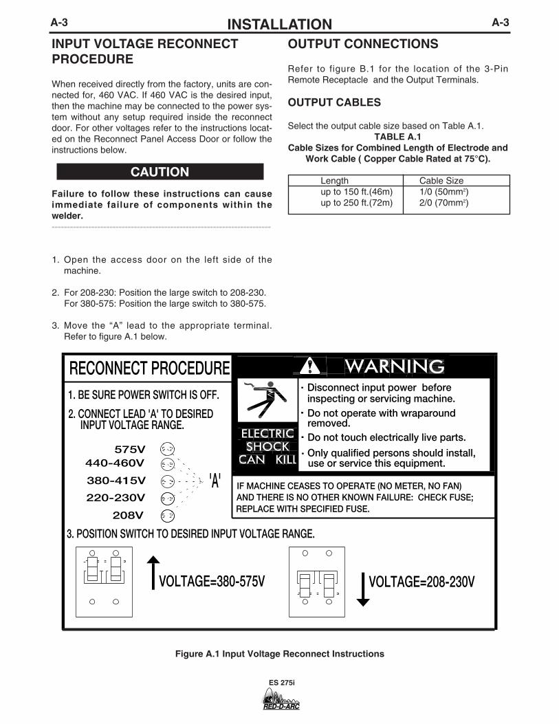
OUTPUT CONNECTIONS
Refer to figure B.1 for the location of the 3-PinRemote Receptacle and the Output Terminals.
OUTPUT CABLES
Select the output cable size based on Table A.1.TABLE A.1
Cable Sizes for Combined Length of Electrode andWork Cable ( Copper Cable Rated at 75°C).
Length Cable Sizeup to 150 ft.(46m) 1/0 (50mm2)up to 250 ft.(72m) 2/0 (70mm2)
A-3INSTALLATION A-3
INPUT VOLTAGE RECONNECTPROCEDURE
When received directly from the factory, units are con-nected for, 460 VAC. If 460 VAC is the desired input,then the machine may be connected to the power sys-tem without any setup required inside the reconnectdoor. For other voltages refer to the instructions locat-ed on the Reconnect Panel Access Door or follow theinstructions below.
Failure to follow these instructions can causeimmediate failure of components within thewelder.------------------------------------------------------------------------
1. Open the access door on the left side of themachine.
2. For 208-230: Position the large switch to 208-230.For 380-575: Position the large switch to 380-575.
3. Move the “A” lead to the appropriate terminal.Refer to figure A.1 below.
.
.
.
.
Do not touch electrically live parts.
Only qualified persons should install,use or service this equipment.
RECONNECT PROCEDURE1. BE SURE POWER SWITCH IS OFF.
208V
220-230V
380-415V
440-460V 575V
'A'
INPUT VOLTAGE RANGE. removed.Do not operate with wraparoundinspecting or servicing machine.Disconnect input power before
IF MACHINE CEASES TO OPERATE (NO METER, NO FAN)
2. CONNECT LEAD 'A' TO DESIRED
3. POSITION SWITCH TO DESIRED INPUT VOLTAGE RANGE.
AND THERE IS NO OTHER KNOWN FAILURE: CHECK FUSE;
VOLTAGE=380-575V VOLTAGE=208-230V
REPLACE WITH SPECIFIED FUSE.
CAUTION
Figure A.1 Input Voltage Reconnect Instructions

ES 275i
B-1OPERATIONB-1
GENERAL DESCRIPTION
The ES 275i is a 275 amp arc welding power sourcethat utilizes single or three phase input power, to pro-duce constant current output. The welding responseof this Invertec has been optimized for stick (SMAW)and TIG (GTAW).
OPERATIONAL FEATURES
The ES 275i provides continuous total range outputcurrent adjustment, selectable welding modes andlocal or remote output control. Welding characteristicscan be controlled via an arc force control.Additionally, starting characteristics can be adjustedvia a “hot start” control.
WELDING CAPABILITY
The ES 275i is rated at 275 amps, 35% duty cycle(based on a 10 minute cycle). It is also rated at 200amps, 100% duty cycle, and 250 amps, 60% dutycycle.
LIMITATIONS
The ES 275i is not recommended for pipe thawing.
Read and understand this entire section beforeoperating your machine.
SAFETY PRECAUTIONS
ELECTRIC SHOCK can kill.
• Do not touch electrically live parts suchas output terminals or internal wiring.
• Insulate yourself from the work andground.
• Always wear dry insulating gloves.____________________________________
____________________________________
____________________________________
____________________________________
Only qualified personnel should operate this equip-ment. Observe all safety information throughout thismanual.
WARNING
FUMES AND GASEScan be dangerous.
• Keep your head out of fumes.
• Use ventilation or exhaust toremove fumes from breathingzone.
ARC RAYScan burn.
• Wear eye, ear and bodyprotection.
WELDING, CUTTING and GOUGING SPARKScan cause fire or explosion
• Keep flammable material away.
• Do not weld, cut or gouge oncontainers that have held com-
bustibles.

B-2OPERATIONB-2
1. POWER SWITCH - Place the lever in the “ON”position to energize the machine. When the power is onthe output will be energized in (STICK) SMAW mode and(TIG) GTAW if the remote is set to local control. Atpower up the thermal Light and Fan will turn on forapproximately 3 seconds.
2. OUTPUT CONTROL - This controls the outputcurrent. Control is provided over the entire output rangeof the power source with (1) turn of the control knob. Thiscontrol may be adjusted while under load to changepower source output. When using remote control thisfunction becomes the limit setting.
3. LOCAL/REMOTE SWITCH - Place in the“LOCAL” position to allow output adjustment at themachine. Place in the “REMOTE” position to allow outputadjustment at remote pot or amptrol. In Remote, themachine output control pot is the limit setting for remotecontrol.
4. MODE SWITCHCC -Stick SMAW Use this mode for all stick welding.Output energized when machine is on.
GTAW Optimized for touch start use. Short circuit currentis limited to approximately 20 amps to aid in touch start-ing.
5. HOT START - Controls the amount of starting ener-gy in CC Stick SMAW. The Hot Start can be eitherturned on or off. When on, it provides a striking current at260% of the set current or 275A whichever is larger thenquickly reverts to the set current in 0.4 second.
6. ARC FORCE - This control functions in CC StickSMAW modes to adjust the Arc Force. The arc issoft at the minimum settings and more forceful ordriving at the maximum settings. Higher spatterlevels may be present at the maximum settings.Full range is from -10(Soft) to +10(Crisp)
ES 275i
CONTROLS AND SETTINGS
All operator controls and adjustments are located on the case front of the ES 275i. Refer to Figure B.1 and corre-sponding explanations.
FIGURE B.1 — CASE FRONT CONTROLS.
LOCAL
REMOTE
REMOTE
ARC FORCE HOT START
-10 +10
OUTPUT
CC STICK
TIG
ON
ON
OFF
OFFOFF
1
2
3
4
9
7
6
8
5

B-3OPERATIONB-3
7. OUTPUT TERMINALS - These quick discon-nect terminals are compatible with TWECO®* con-nectors. The terminal provide connection points forthe electrode and work cables. Refer to OutputConnection in the Installation chapter for propercable sizes. For positive polarity welding connectthe electrode cable to the positive terminal and thework cable to the negative terminal. To weld nega-tive polarity reverse the electrode and work cables.
* TWECO® is registered trademark of Thermo Dyne Corporation.
8. THERMAL SHUTDOWN INDICATOR -This light will illuminate if an internal thermostathas been activated. Machine output will return afterthe internal components have returned to a normaloperating temperature. See Thermal Protectionlater in this Operation chapter.
9. 3-PIN REMOTE RECEPTACLE 3-Pin remote control allows for remote control ofthe Output current.
CONSTANT CURRENT PROCESSES
MANUAL ARC WELDING (STICK)The Invertec may be utilized as a manual DC arcwelder with the electrode cable, work cable, and elec-trode holder being the only equipment required.
AIR CARBON ARC CUTTINGAir carbon arc cutting may be performed with theInvertec within its output rating using 1/4”(6.4mm)diameter carbon rods. Output cables, an air carbonarc electrode cable assembly, and a source of com-pressed air are required.
NOTE:1. The electronic protection circuit in the ES 275i will
limit the current to approximately 300 amps.
TIG WELDINGThe ES 275i is capable of touch start TIG welding. Anelectrode cable, work cable, TIG torch, and gas sup-ply with regulator are required.
Touch starting is done as follows:
1. Place the shield cup edge on the work piece.2. Rock the tungsten down to touch.3. Trigger the output.-If using remote control.4. Gently rock back the tungsten from the work-
piece.
Note: The short circuit current is limited to 20 amps toaid in touch starting. Panel output controlbecomes the current limit setting when inremote control.
PARALLEL OPERATIONThe Invertec’s are operable in parallel. For bestresults, the currents of each machine should be rea-sonably well shared. As an example, with twomachines set up in parallel for a 300 amp procedure,each machine should be set to deliver approximately150 amps, not 200 amps from one and 100 ampsfrom the other. This will minimize nuisance feedbackconditions. In general, more than two machines in par-allel will not be effective due to the voltage require-ments of procedures in that power range.
To set machine outputs, start with output control potsand arc force pots in identical positions. Adjust out-puts and arc forces to maintain current sharing whileestablishing the proper output current.
OVERLOAD PROTECTIONThe machine is electrically protected from producinghigh output currents. Should the output currentexceed 300A, an electronic protection circuit willreduce the current to less than 200A. The machinewill continue to produce this low current until the pro-tection circuit is reset. Reset occurs when the outputload is removed.
Note: When TIG welding with the Output Knob at orabove 275Amps the Arc may go out.
THERMAL PROTECTIONThermostats protect the machine from excessiveoperating temperatures. Excessive temperatures maybe caused by a lack of cooling air or operating themachine beyond the duty cycle and output rating. Ifexcessive operating temperature should occur, thethermostats will prevent output voltage or current.
Thermostats are self-resetting once the machine coolssufficiently.
FANThe cooling fan on the V275-S operates once 15amps of welding current is drawn and for 7 minutesafter the output current has stopped flowing.
The fan will also run anytime the machine has overheated.
ES 275i

D-1MAINTENANCED-1
INPUT FILTER CAPACITORDISCHARGE PROCEDURE
1. Turn off input power or disconnect input powerlines.
2. Remove the 5/16" hex head screws from the sideand top of the machine and remove wrap-aroundmachine cover.
3. Be careful not to make contact with the capacitorterminals that are located in the top and bottom ofthe Power Board.
4. Obtain a high resistance and high wattage resistor(25-1000 ohms and 25 watts minimum). This resis-tor is not supplied with machine. NEVER USE A SHORTING STRAP FOR THIS PROCEDURE.
5. Locate the four capacitor terminals (large hex headcap screws) shown in Figure D.1. One pair at thetop and one pair at the bottom of the Power Board.
6. Use electrically insulated gloves and insulated pli-ers. Hold body of the resistor and connect resistorleads across the two capacitor terminals. Holdresistor in place for 10 seconds. DO NOT TOUCHCAPACITOR TERMINALS WITH YOUR BAREHANDS.
7. Repeat discharge procedure for the capacitor onother two terminals.
8. Check voltage across terminals of all capacitorswith a DC voltmeter. Polarity of capacitor terminalsis marked on PC board above terminals. Voltageshould be zero. If any voltage remains, repeat thiscapacitor discharge procedure.
ES 275i
ELECTRIC SHOCK can kill.• Have an electrician install and service
this equipment.• Turn the input power off at the fuse
box before working on equipment.• Do not touch electrically hot parts.• Prior to Performing preventative main-
tenance, perform the following capaci-tor discharge procedure to avoid elec-tric shock.
---------------------------------------------------------------------
WARNING
UPPER CAPACITOR TERMINALS
LOWER CAPACITOR TERMINALS
INSULATEDGLOVES
INSULATEDPLIERS
POWERRESISTOR
POWERBOARD
RIGHT SIDE OF MACHINE
FIGURE D.1 — LOCATION OF INPUT FILTER CAPACITOR TERMINALS.

D-2MAINTENANCED-2
ROUTINE MAINTENANCE
1. Perform the following preventive maintenance pro-cedures at least once every six months. It is goodpractice to keep a preventive maintenance record;a record tag attached to the machine works best.
2. Remove the machine wrap-around cover and per-form the input filter capacitor discharge procedure(detail at the beginning of this chapter).
3. Keeping the machine clean will result in cooleroperation and higher reliability. Be sure to clean thefollowing areas with a low pressure air stream. Seefigure D.2 for component locations.
•Power and control printed circuit boards
•Power switch
•Main transformer
•Input rectifier
•Heat sink fins
•Input Filter Capacitors
•Output Terminals
4. Examine capacitors for leakage or oozing. Replaceif needed.
5. Examine the sheet metal case for dents or break-age. Repair the case as required. Keep the case ingood condition to ensure that high voltage parts areprotected and correct spacings are maintained. Allexternal sheet metal screws must be in place toassure case strength and electrical ground continu-ity.
6. Check electrical ground continuity. Using an ohm-meter, measure resistance between either outputterminal and an unpainted surface of the machinecase. (See Figure D.2 for locations.) Meter readingshould be 500,000 ohms or more. If meter readingis less than 500,000 ohms, check for electrical com-ponents that are not properly insulated from thecase. Correct insulation if needed.
7. Replace machine cover and screws.
FILTER CAPACITORCONDITIONING
A protection circuit is included to monitor the voltageacross filter capacitors C1 and C2. In the event thatthe capacitor voltage is too high, the protection circuitwill prevent output. Nominal trip setting is at 230/460VAC +15%. Reset occurs about 3% lower (230/460VAC +12%).
On new installations, the protection circuit may alsoprevent output providing all these circumstances aremet:
1. Machine is connected for 380-415 or 440-460 VACinput.
2. Machine did not have power applied for manymonths.
3. Machine will not produce output when power is firstswitched on.
If these circumstances apply, the proper action is toswitch the machine on and let it idle for up to 30 min-utes. This is required to condition the filter capacitorsafter an extended storage time. The protection circuitwill automatically reset once the capacitor conditioningand resultant voltage levels are acceptable. It may benecessary to turn the power switch off and back onagain after this period.
ES 275i

ES 275i
D-3MAINTENANCED-3
FIGURE D.2 — LOCATION OF MAINTENANCE COMPONENTS.
SWITCH BOARDHEAT SINK ASSEMBLY
CONTROL PC BOARD
CHOKE ASSEMBLY
OUTPUT RECTIFIERHEATSINK FINS
MAIN TRANSFORMER
OUTPUT TERMINALSPOWER SWITCH
CENTER ASSEMBLY
COOLING FANS
CASE BACK ASSEMBLY
POWER PC BOARD
CASE FRONT ASSEMBLY
WRAP-AROUND
BASE AND ASSEMBLIES

ES 275i
E-1TROUBLESHOOTING E-1
If for any reason you do not understand the test procedures or are unable to perform the tests/repairs safely, contact yourLocal Authorized Field Service Facility for technical troubleshooting assistance before you proceed.
CAUTION
This Troubleshooting Guide is provided to help youlocate and repair possible machine malfunctions.Simply follow the three-step procedure listed below.
Step 1. LOCATE PROBLEM (SYMPTOM).Look under the column labeled “PROBLEM (SYMP-TOMS)”. This column describes possible symptomsthat the machine may exhibit. Find the listing thatbest describes the symptom that the machine isexhibiting.
Step 2. POSSIBLE CAUSE.The second column labeled “POSSIBLE CAUSE” liststhe obvious external possibilities that may contributeto the machine symptom.
Step 3. RECOMMENDED COURSE OF ACTIONThis column provides a course of action for thePossible Cause, generally it states to contact yourlocal Authorized Field Service Facility.
If you do not understand or are unable to perform theRecommended Course of Action safely, contact yourlocal Authorized Field Service Facility.
HOW TO USE TROUBLESHOOTING GUIDE
Service and Repair should only be performed by Trained Personnel. Unauthorized repairs performedon this equipment may result in danger to the technician and machine operator and will invalidateyour factory warranty. For your safety and to avoid Electrical Shock, please observe all safety notesand precautions detailed throughout this manual.
__________________________________________________________________________
WARNING

ES 275i
E-2TROUBLESHOOTING & REPAIRE-2
_______________________________CAUTION: Sometimes machine failuresappear to be due to PC board failures. Theseproblems can sometimes be traced to poorelectrical connections. To avoid problemswhen troubleshooting and replacing PCboards, please use the following procedure:
1. Determine to the best of your technicalability that the PC board is the most likelycomponent causing the failure symptom.
2. Check for loose connections at the PCboard to assure that the PC board is prop-erly connected.
3. If the problem persists, replace the sus-pect PC board using standard practices toavoid static electrical damage and electri-cal shock. Read the warning inside thestatic resistant bag and perform the follow-ing procedures:
P.C. Board can be dam-aged by static electricity.
- Remove your body’s stat-ic charge before openingthe static-shielding bag.Wear an anti-static wriststrap. For safety, use a 1Meg ohm resistive cordconnected to a groundedpart of the equipmentframe.
- If you don’t have a wriststrap, touch an unpainted,grounded, part of the
equipment frame. Keep touching the frame toprevent static build-up. Be sure not to touchany electrically live parts at the same time.
- Tools which come in contact with the P.C.Board must be either conductive, anti-static orstatic-dissipative.
ELECTRIC SHOCK can kill.Have an electrician installand service this equip-ment. Turn the input powerOFF at the fuse box beforeworking on equipment. Donot touch electrically hotparts.
- Remove the P.C. Board from the static-shielding bag and place it directly into theequipment. Don’t set the P.C. Board on ornear paper, plastic or cloth which could havea static charge. If the P.C. Board can’t beinstalled immediately, put it back in the static-shielding bag.
- If the P.C. Board uses protective shortingjumpers, don’t remove them until installationis complete.
- If you return a P.C. Board for credit, it mustbe in the static-shielding bag. This will preventfurther damage and allow proper failure analy-sis.
4. Test the machine to determine if the fail-ure symptom has been corrected by thereplacement PC board.
NOTE: It is desirable to have a spare (knowngood) PC board available for PC board trou-bleshooting.
NOTE: Allow the machine to heat up so thatall electrical components can reach their oper-ating temperature.
5. Remove the replacement PC board andsubstitute it with the original PC board torecreate the original problem.
a. If the original problem does not reap-pear by substituting the originalboard, then the PC board was not theproblem. Continue to look for badconnections in the control wiring har-ness, junction blocks, and terminalstrips.
b. If the original problem is recreated bythe substitution of the original board,then the PC board was the problem.Reinstall the replacement PC boardand test the machine.
6. Always indicate that this procedure wasfollowed when warranty reports are to besubmitted.
NOTE: Following this procedure and writing on thewarranty report, “INSTALLED AND SWITCHED PCBOARDS TO VERIFY PROBLEM,” will help avoiddenial of legitimate PC board warranty claims.
PC BOARD TROUBLESHOOTING PROCEDURES
WARNING
ATTENTIONStatic-SensitiveDevicesHandle only atStatic-SafeWorkstations
Reusable ContainerDo Not Destroy

ES 275i
E-3TROUBLESHOOTING E-3
Observe all Safety Guidelines detailed throughout this manual
OUTPUT PROBLEMS
PROBLEMS(SYMPTOMS)
POSSIBLE AREAS OFMISADJUSTMENT(S)
RECOMMENDEDCOURSE OF ACTION
Major physical or electrical damageis observed when cover wrap-aroundis removed.
The machine is dead - no output.
No output but the fan operates nor-mally.
1. The input power switch must bein the ON position.
2. Make sure the input voltage iscorrect for the machine.
3. If the machine is set for single-phase operation, inspect toassure that the WHITE andBLACK leads are connectedproperly and the RED lead is notconnected and is insulated.
4. Check that the input voltage set-up switch and jumper “A” (thereconnect auxiliary jumper) are inthe proper position for the inputvoltage being applied. Refer toInput Voltage ReconnectProcedure in the InstallationChapter.
5. Check continuity of the 0.6-ampslow blow fuse located on thereconnect panel.
1. If the machine has not been usedfor a long time and is connectedfor 380 VAC or higher, thecapacitors may need “condition-ing”. See Input Filter CapacitorConditioning.
2. The machine may be overheated.Check the thermal indicator light.Wait for the machine to cool andthe thermostats to reset.
If all recommended possible areas ofmisadjustment have been checkedand the problem persists, Contactyour local Authorized Field ServiceFacility.
If for any reason you do not understand the test procedures or are unable to perform the tests/repairs safely, con-tact your local authorized field service facility for technical troubleshooting assistance before you proceed.
CAUTION

ES 275i
E-4TROUBLESHOOTING E-4
Observe all Safety Guidelines detailed throughout this manual
OUTPUT PROBLEMS
PROBLEMS(SYMPTOMS)
POSSIBLE AREAS OFMISADJUSTMENT(S)
RECOMMENDEDCOURSE OF ACTION
Output turns on momentarily, thenswitches off and repeats cycle.
Remote output control not functioning. The machine operatesnormally on LOCAL control.
1. Check the input voltages andreconnection procedures. Makesure the input voltage is correctfor the machine. See InputVoltage Reconnect Procedure.
2. Check or replace remote controldevice. (If used)
1. Make sure the Local/Remoteswitch (S3) is in the REMOTEposition.
2. The remote control device maybe faulty. Replace.
3. The Local/Remote switch mustbe in the LOCAL position unlessa remote control device isattached to the remotereceptacle.
If all recommended possible areas ofmisadjustment have been checkedand the problem persists, Contactyour local Authorized Field ServiceFacility.
If for any reason you do not understand the test procedures or are unable to perform the tests/repairs safely, con-tact your local authorized field service facility for technical troubleshooting assistance before you proceed.
CAUTION
ES 275i
E-5TROUBLESHOOTING E-5
Observe all Safety Guidelines detailed throughout this manual
OUTPUT PROBLEMS
PROBLEMS(SYMPTOMS)
POSSIBLE AREAS OFMISADJUSTMENT(S)
RECOMMENDEDCOURSE OF ACTION
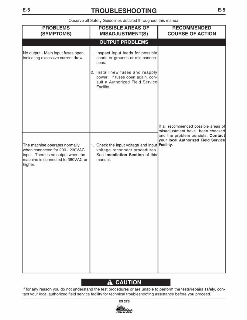
No output - Main input fuses open,indicating excessive current draw.
The machine operates normallywhen connected for 200 - 230VACinput. There is no output when themachine is connected to 380VAC orhigher.
1. Inspect input leads for possibleshorts or grounds or mis-connec-tions.
2. Install new fuses and reapplypower. If fuses open again, con-sult a Authorized Field ServiceFacility.
1. Check the input voltage and inputvoltage reconnect procedures.See Installation Section of thismanual.
If all recommended possible areas ofmisadjustment have been checkedand the problem persists, Contactyour local Authorized Field ServiceFacility.
If for any reason you do not understand the test procedures or are unable to perform the tests/repairs safely, con-tact your local authorized field service facility for technical troubleshooting assistance before you proceed.
CAUTION
ES 275i
E-6TROUBLESHOOTING E-6
Observe all Safety Guidelines detailed throughout this manual
OUTPUT PROBLEMS
PROBLEMS(SYMPTOMS)
POSSIBLE AREAS OFMISADJUSTMENT(S)
RECOMMENDEDCOURSE OF ACTION
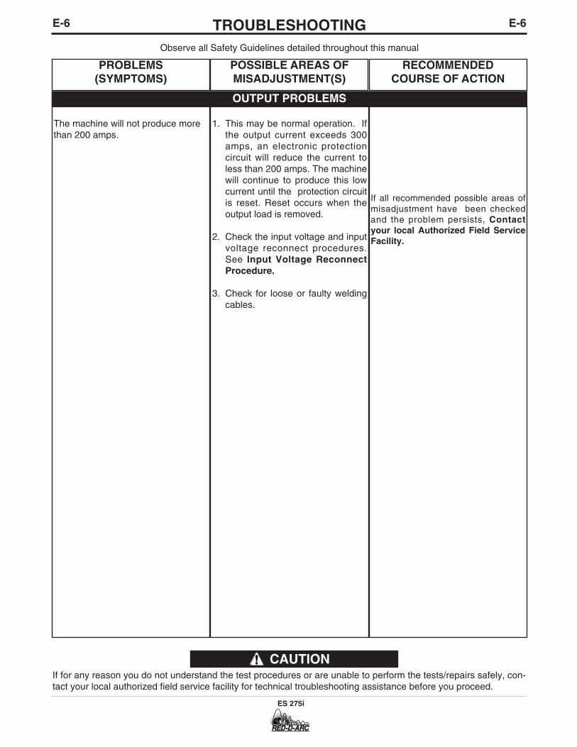
The machine will not produce morethan 200 amps.
1. This may be normal operation. Ifthe output current exceeds 300amps, an electronic protectioncircuit will reduce the current toless than 200 amps. The machinewill continue to produce this lowcurrent until the protection circuitis reset. Reset occurs when theoutput load is removed.
2. Check the input voltage and inputvoltage reconnect procedures.See Input Voltage ReconnectProcedure.
3. Check for loose or faulty weldingcables.
If all recommended possible areas ofmisadjustment have been checkedand the problem persists, Contactyour local Authorized Field ServiceFacility.
If for any reason you do not understand the test procedures or are unable to perform the tests/repairs safely, con-tact your local authorized field service facility for technical troubleshooting assistance before you proceed.
CAUTION

ES 275i
E-7TROUBLESHOOTING E-7
Observe all Safety Guidelines detailed throughout this manual
WELDING PROBLEMS
PROBLEMS(SYMPTOMS)
POSSIBLE AREAS OFMISADJUSTMENT(S)
RECOMMENDEDCOURSE OF ACTION
Poor welding, weld settings drift, oroutput power is low.
Poor stick electrode welding performance. The arc pops out.
The thermal light and fan keep turn-ing on and off.
1. Make sure the machine settingsare correct for the weld processbeing used.
2. Check machine performance onLOCAL control. If OK then theremote control device may befaulty. Check or replace.
3. Check the input voltages andinput voltage reconnectprocedures. See InstallationSection of this manual.
4. Check for loose or faulty weldingcables.
1. Check for loose or faulty weldingcables.
2. Is the electrode DRY? Try weld-ing with another electrode from adifferent container. Make sureyou have the correct electrode forthe application.
3. Make sure the machine settingsare correct for the weld processbeing used.
1. Check the input voltage section.
2. Check for blockage of vents,which restricts air flow into or outof the machine.
If all recommended possible areas ofmisadjustment have been checkedand the problem persists, Contactyour local Authorized Field ServiceFacility.
If for any reason you do not understand the test procedures or are unable to perform the tests/repairs safely, con-tact your local authorized field service facility for technical troubleshooting assistance before you proceed.
CAUTION

F-1DIAGRAMSF-1
ES 275i
R2
AR
C F
OR
CE
WE
LD
MO
DE
OF
F
328
327
304
SM
AW
GT
AW
VIE
W O
F C
ON
NE
CT
OR
ON
PC
BO
AR
DE
LEC
TR
ICA
L S
YM
BO
LS P
ER
E15
37.
OH
MS
/WA
TT
S
CO
MP
ON
EN
T V
ALU
EU
NIT
S:
RE
SIS
TO
RS
:
MF
D/V
OLT
SC
AP
AC
ITO
RS
:
8LA
TC
H
0F C
ON
NE
CT
OR
J5
EX
AM
PLE
: TH
IS IS
PIN
7
32
LEA
D C
OLO
RIN
G C
OD
E:
B-B
LAC
K 21 8
G-G
RE
EN
O-O
RA
NG
ER
-RE
D
CO
NN
EC
TO
R P
IN N
UM
BE
RS
:
7 14
U-B
LUE
Y-Y
ELL
OW
W-W
HIT
E
1
3 J5
R4
G43
65-2
A.02
WIR
ING
DIA
GR
AM
- R
ED
-D-A
RC
ES
275i
ON
HO
TS
TA
RT
Y
TH
ER
MA
L
+-
WB
3
26
7
PRI-OUT
PRI-IN
SEC BOOST
TP
1
INP
UT
BR
IDG
E _ + DEBC
F
A
_
PO
WE
R S
WIT
CH
W B
R1
OU
TP
UT
376375
377
TP
2T
P3
380-
415V
575V
220-
230V
440-
460V
208V
0.6
AM
PS
LOW
BLO
W
SEC
BOOST
PRI-IN
PRI-OUT
NO
TES:
N.A
. 1.
FO
R M
ACHI
NES
WIT
H RE
D, B
LACK
AND
WH
ITE
POW
ER C
OR
DS
FOR
SIN
GLE
PHA
SE IN
PUT:
CO
NNE
CT
GRE
EN L
EAD
TO G
RO
UND
PER
NAT
ION
AL E
LEC
TRIC
AL C
OD
E.
CO
NNE
CT
BLAC
K AN
D W
HIT
E LE
ADS
TO S
UPPL
Y CI
RCUI
T.
WR
AP R
ED L
EAD
WIT
H TA
PE T
O P
RO
VIDE
600
V. IN
SULA
TIO
N.
FOR
THRE
E PH
ASE
INPU
T: C
ON
NEC
T G
REEN
LEA
D TO
GR
OU
ND P
ER N
ATIO
NAL
ELE
CTR
IC C
OD
E.
CO
NNE
CT
BLAC
K, R
ED &
WH
ITE
LEAD
S TO
SUP
PLY
CIRC
UIT.
N.C
. PL
ACE
"A" L
EAD
ON
APPR
OPR
IATE
CO
NNE
CTI
ON
FOR
INPU
T VO
LTAG
E.
C
ON
NEC
TIO
N SH
OW
N IS
FO
R 57
5V O
PERA
TIO
N.
N.B
. SI
NCE
CO
MPO
NEN
TS O
R CI
RCUI
TRY
OF
A PR
INTE
D CI
RCUI
T BO
ARD
MAY
CH
ANG
E W
ITH
OU
T AF
FEC
TIN
G
T
HE IN
TERC
HAN
GEA
BILI
TY O
F A
CO
MPL
ETE
BOAR
D, T
HIS
DIAG
RAM
MAY
NO
T SH
OW
THE
EXA
CT
CO
MPO
NEN
TS O
R CI
RCUI
TRY
HAV
ING
A C
OM
MO
N C
OD
E NU
MBE
R.
BA
SE
CA
SE
FR
ON
T
PR
OT
EC
TIV
E B
ON
DIN
G C
IRC
UIT
375B
375B
324
H2
18VU
W
1
303
304A
H1
H3
H4
H5
H6
FA
N
FA
N
CR
1C
R1
48
01
26
H1A
63
52
4
H2
H1
H3
H4
H5
H6
H1
H2
H4
H6
H3
H5
H3A
H3A
H3C
H3D
H1D
H1C
H1C
H1B
H1D
FA
N R
EL
AY
RN
.A.
207
209
A1
H1B
A1
A
A
N.C
.
209
205
201
204
208
206
203A
207A
202A
77
76
75
SW
ITC
H P
C B
OA
RD
CO
NT
RO
L P
C B
OA
RD
CA
SE
BA
CK
GN
D2
G
GND1
LINE
CO
RD
208
204
20120
5
SHUNT
X4
X2
X4
L1
X2
X7
X8
X5
X6
X1
X3
RE
AC
TO
R
L2
RE
AC
TO
R
MA
INT
RA
NS
FO
RM
ER
D1A
D1B
D2A
D2B
X7
X6
RIGHT
LEFT
X8
X5
X1
X3
OU
TP
UT
RE
CT
IFIE
R
L3
OU
TP
UT
CH
OK
E
207A
382
383
388
387
RE
MO
TE
RE
CE
PT
AC
LE
SNUBBER PC BOARD
R3
386
385
384
381
204
208
201
205
WR
C2
C1
207A
202A
206
203A
209
R22
2
W22
1
L4
L5
CA
SE
FR
ON
T (
RE
AR
VIE
W)
TP
4
C4
C3
TP
6 TP
5
W R
T1
T4
T3
AUXILIARYTRANSFORMER
T2
D3A
D3B
HE
AT
SIN
K
229
376
W 327
324
B 375
303
R(T
4)
R(T
3)W
(T4)
310
307
308
313
J10
J3 J4
377
328
304
330
1 2 3 4 65
1 2 3 46 57 8 9 10 11 12
309
311
98 7 10
387
388
316
320
382
383
229
380
J2
277
76 75
1 2 4 5 87 6 12 3 9
R22
2W
221
1 2
10 11
J1
316
320
318
317 S4
L1 L2 L3
L1 L2 L3
(W)
(V)
(U)
W(T
3)
S1
D4
C1,
C2
SW
ITC
H B
OA
RD
CA
PA
CIT
OR
S, 2
200/
500
C3,
C4
OU
TP
UT
BY
-PA
SS
CA
PA
CIT
OR
S, .
05/6
00C
R1
FA
N R
ELA
Y C
OIL
, 12V
DC
D1A
,D1B
OU
TP
UT
DIO
DE
,D
2A,D
2BO
UT
PU
T D
IOD
E,
D3A
,D3B
OU
TP
UT
DIO
DE
,D
4IN
PU
T R
EC
ITIE
R B
RID
GE
L1,L
2O
UT
PU
T R
EA
CT
OR
L3O
UT
PU
T IN
DU
CT
OR
(C
HO
KE
)L4
,L5
RF
TO
RO
ID C
HO
KE
SR
1O
UT
PU
T C
ON
TR
OL
PO
TE
NT
IOM
ET
ER
,10K
/2R
2A
RC
FO
RC
E P
OT
EN
TIO
ME
TE
R, 1
0K/2
R3,
R4
OU
TP
UT
LO
AD
RE
SIS
TO
RS
, 100
/25
S1
INP
UT
PO
WE
R S
WIT
CH
S2A
,S2B
RE
CO
NN
EC
T S
WIT
CH
ES
S3
OU
TP
UT
RE
CT
IFIE
R H
EA
TS
INK
TH
ER
MO
ST
AT
S4
SW
ITC
H B
OA
RD
HE
AT
SIN
K T
HE
RM
OS
TA
TT
1M
AIN
TR
AN
SF
OR
ME
RT
2A
UX
ILIA
RY
TR
AN
SF
OR
ME
RT
3,T
4C
UR
RE
NT
TR
AN
SF
OR
ME
RT
P1,
TP
2,T
P3
INP
UT
MO
V, 6
60V
AC
TP
4,T
P5
OU
TP
UT
MO
V, 3
20V
AC
TP
6O
UT
PU
T M
OV
, 150
V A
C
S3
318
317
J5
B
AC
380
LO
CA
L
RE
MO
TE
304A
330
77 277
202
206
203A
202
202A
203
203
207
PR
IMA
RY
RE
CO
NN
EC
T S
WIT
CH
ES
(RE
AR
VIE
W)
(SH
OW
N IN
380
-575
V P
OS
ITIO
N)
S2A
S2B
311
310
308
313
307
309
1 4 27 8 653
NO
TE:
This
dia
gram
is fo
r re
fere
nce
only
. It
may
not
be
accu
rate
for
all m
achi
nes
cove
red
by
this
man
ual.
The
sp
ecifi
c d
iagr
am fo
r a
par
ticul
ar c
ode
is p
aste
din
sid
e th
e m
achi
ne o
n on
e of
the
enc
losu
re p
anel
s. I
f the
dia
gram
is il
legi
ble
, writ
e to
the
Ser
vice
Dep
artm
ent
for
a re
pla
cem
ent.
Giv
e th
e eq
uip
men
t co
de
num
ber
..
WIRING DIAGRAM- CODE: 10994
F-2DIAGRAMSF-2
ES 275i
L119
81A.0
2
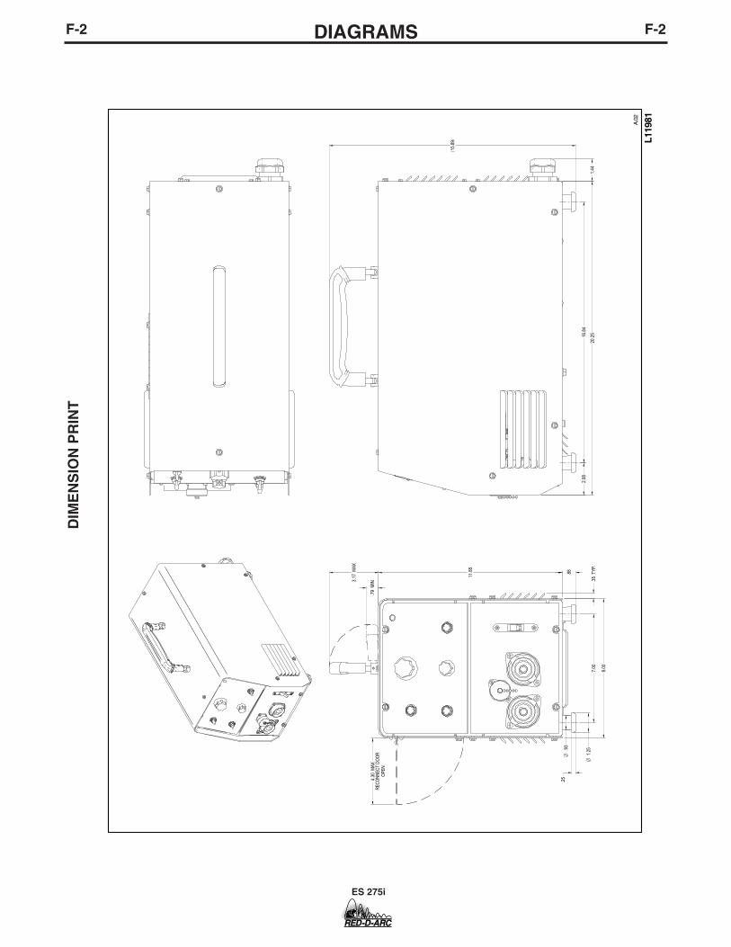
9.00
11.8
5
20.2
5
3.17
MAX
.79
MIN
.88
.25
7.00
16.8
42.
08
4.30
MAX
REC
ON
NEC
T D
OO
RO
PEN
1.25
O
.93
O
15.8
9
.35
TYP.
1.44
DIM
EN
SIO
N P
RIN
T

ES 275i
NOTES

RED-D-ARC ES 275i
P-477P-477
PARTS LIST FOR
Red-D-Arc ES 275i
RETURN TO MAIN INDEX
This parts list is provided as an informative guide only.
This information was accurate at the time of printing. However, since thesepages are regularly updated in Lincoln Electric’s official Parts Book (BK-34),always check with your Lincoln parts supplier for the latest parts information.
11-12-2002RED-D-ARC ES 275i
P-477-AP-477-A
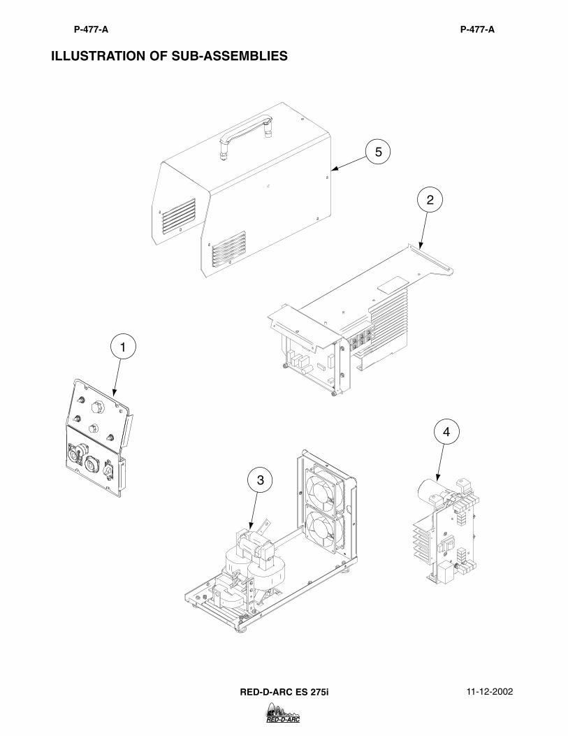
ILLUSTRATION OF SUB-ASSEMBLIES
1
3
4
2
5

11-12-2002RED-D-ARC ES 275i
Do Not use this Parts List for a machine if its code number is not listed. Contact the Service Department for anycode numbers not listed.
Use the Illustration of Sub-Assemblies page and the table below to determine which sub assembly page andcolumn the desired part is located on for your particular code machine.
P-477-A.1P-477-A.1
Red-D-Arc ES 275i
For Code: 10994
CODE NO.
10994 1 1 1 1 1 1
65
Wra
paro
und
Ass
embl
y
P477-G
5
Sw
itch
Boa
rd H
eats
ink
Ass
embl
y
P477-F
4
Bas
e A
ssem
bly
& C
ase
Bac
kA
ssem
bly
P477-E
3
Cen
ter
Ass
embl
y
P477-D
2
Cas
e F
ront
Ass
embl
y
P477-C
1
Mis
cella
neou
s Ite
ms
P477-B.2
SUB ASSEMBLYPAGE NAME
PAGE NO.
Sub Assembly ItemNo.
RETURN TO MAIN INDEX

Input Lead Assembly S18573-13 1 XCord Grip Connector S19999 1 XConduit Lock Nut T14370-3 1 XElectrical Kit S25435 1 X
MISCELLANEOUS ITEMS (THESE ITEMS ARE NOT ILLUSTRATED)
* Recommended Spare Part
11-12-2002RED-D-ARC ES 275i
Use only the parts marked “x” in the column under theheading number called for in the model index page.
# Indicates a change this printing.
P-477-B.1
DESCRIPTION PART NO. QTY. 1 2 3 4 5 6 7 8 9
P-477-B.1

RED-D-ARC ES 275i
NOTES

11-12-2002RED-D-ARC ES 275i
P-477-CP-477-C
Case Front Assembly
1
2
2A
1220
1317
21
15
14 9A8A
3A
22
9
10
10B
18
10A
19
8
4A7
5
36
4
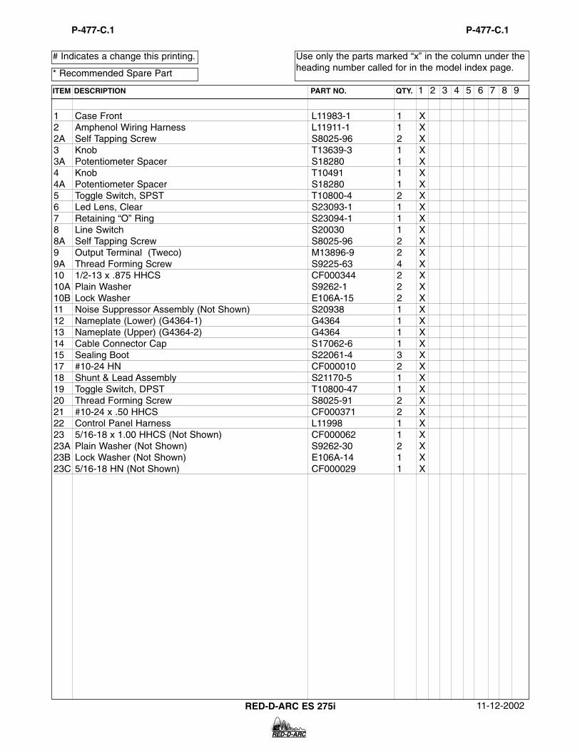
1 Case Front L11983-1 1 X2 Amphenol Wiring Harness L11911-1 1 X2A Self Tapping Screw S8025-96 2 X3 Knob T13639-3 1 X3A Potentiometer Spacer S18280 1 X4 Knob T10491 1 X4A Potentiometer Spacer S18280 1 X5 Toggle Switch, SPST T10800-4 2 X6 Led Lens, Clear S23093-1 1 X7 Retaining “O” Ring S23094-1 1 X8 Line Switch S20030 1 X8A Self Tapping Screw S8025-96 2 X9 Output Terminal (Tweco) M13896-9 2 X9A Thread Forming Screw S9225-63 4 X10 1/2-13 x .875 HHCS CF000344 2 X10A Plain Washer S9262-1 2 X10B Lock Washer E106A-15 2 X11 Noise Suppressor Assembly (Not Shown) S20938 1 X12 Nameplate (Lower) (G4364-1) G4364 1 X13 Nameplate (Upper) (G4364-2) G4364 1 X14 Cable Connector Cap S17062-6 1 X15 Sealing Boot S22061-4 3 X17 #10-24 HN CF000010 2 X18 Shunt & Lead Assembly S21170-5 1 X19 Toggle Switch, DPST T10800-47 1 X20 Thread Forming Screw S8025-91 2 X21 #10-24 x .50 HHCS CF000371 2 X22 Control Panel Harness L11998 1 X23 5/16-18 x 1.00 HHCS (Not Shown) CF000062 1 X23A Plain Washer (Not Shown) S9262-30 2 X23B Lock Washer (Not Shown) E106A-14 1 X23C 5/16-18 HN (Not Shown) CF000029 1 X
* Recommended Spare Part
11-12-2002RED-D-ARC ES 275i
Use only the parts marked “x” in the column under theheading number called for in the model index page.
# Indicates a change this printing.
P-477-C.1
ITEM DESCRIPTION PART NO. QTY. 1 2 3 4 5 6 7 8 9
P-477-C.1

11-12-2002RED-D-ARC ES 275i
P-477-DP-477-D
Center Assembly
10 2
2C1614
1513
3
12
5
7A5A
2B6D
6B
6C
6H 6K
6L6M
6N
6J
6E
6F
6S6P
6W6R
6Q
6G
1819 1
8
9
9A
8B
Par
t of I
tem
20
8C
177
8A

1 Center Panel G4343 1 X2 Reconnect Panel M19656 1 X2A Rivet T12584-7 2 X2B Plain Washer S9262-3 2 X3 Fuse Holder S10433-1 1 X4 Fuse (Not Shown) T10728-30 2 X5 Control Box L11982 1 X5A Self Tapping Screw S8025-92 4 X6 Output Rectifier Assembly L11974 1 X6B Insulator T11267-A 3 X6C Insulator T11267-B 3 X6D Thread Forming Screw S9225-17 3 X6E Output Rectifier Heatsink L11971 1 X6F Diode Module Assembly S25520-2 2 X6G Diode Module Assembly S25520-1 1 X6H 1/4-28 HJN CF000060 6 X6J Plain Washer S9262-23 6 X6K Lock Washer E106A-2 6 X6L Thermostat T13359-12 1 X6M Socket Head Cap Screw T9447-61 2 X6N Snubber PC Board Assembly M19532-1 1 X6P 1/4-20 x .625 HHCS CF000013 6 X6Q Plain Washer S9262-23 6 X6R Spring Washer T12735-4 6 X6S Socket Head Cap Screw T9447-91 3 X6T Plain Washer (Not Shown) S9262-30 1 X6U Lock Washer (Not Shown) E106A-14 1 X6V 5/16-18 x .75 HHCS (Not Shown) CF000040 1 X6W Lead, Flat Copper T14190-1 2 X7 Control PC Board Assembly G4372-1 1 X7A #10-24 HLN-E1817/1-Nylon Insert T9187-13 3 X8 Diode Bridge M15454-8 1 X8A Socket Head Cap Screw T9447-10 2 X8B Pressure Washer T12735-4 2 X8C Input Diode Heatsink M20155 1 X9 DC Relay S15122-12 1 X9A Self Tapping Screw S8025-98 2 X10 Bushing T12380-3 1 X11 M.O.V. Assembly (Not Shown) S18491-1 1 X12 Receptacle T14530-1 5 X13 Decal (Recoonect) (G4364-3) G4364 1 X14 Decal (Low Voltage) (G4364-6) G4364 1 X15 Decal (High Voltage) (G4364-7) G4364 1 X16 #6-32 x .375 PPNHS CF000337 4 X17 Switch Pin S20322 1 X18 Warning Decal S18469 1 X19 Thread Forming Screw S9225-8 4 X20 Primary Harness (Not Shown) G4377 1 X
* Recommended Spare Part
11-12-2002RED-D-ARC ES 275i
Use only the parts marked “x” in the column under theheading number called for in the model index page.
# Indicates a change this printing.
P-477-D.1
ITEM DESCRIPTION PART NO. QTY. 1 2 3 4 5 6 7 8 9
P-477-D.1

11-12-2002RED-D-ARC ES 275i
P-477-EP-477-E
Base Assembly & Case Back Assembly
2
2A
5A
7A
17
7
9
9A
9B
9C
9E
9D
6
33A
512
13
11
1012A
4A
4B
8
4
1

1 Base G4360-1 1 X2 Mounting Foot S25589 4 X2A Thread Forming Screw S9225-8 4 X3 Choke Assembly L11959 1 X3A Thread Forming Screw S9225-8 2 X4 #10-24HN CF000010 2 X4A Lock Washer E106A-1 1 X4B Plain Washer S9262-27 1 X5 Main Transformer G4304-1 1 X5A Thread Forming Screw S9225-8 2 X6 Decal (Ground Connection) (G4364-4) G4345-4 1 X7 Transformer & Terminal Assembly S25578 1 X7A Self Tapping Screw S8025-92 4 X8 #10-24 HN CF000010 2 X9 Resistor S10404-105 2 X9A #10-24 x 3.00 RHS CF000009 2 X9B Insulating Washer T4479-A 4 X9C Plain Washer S9262-27 2 X9D Lock Washer T9695-1 4 X9E #10-24 HN CF000010 2 X10 Case Back L11984-1 1 X11 Dust Cover S21320 2 X12 Fan (Tube Axial) S18977-3 2 X12A Thread Forming Screw S9225-52 8 X13 #10-24 HN CF000010 2 X15 Rating Plate (Not Shown) (S25567-1A) S25567-1 1 X16 Serial Number Plate (Not Shown) (S25567-1B) S25567-1 1 X17 Thread Forming Screw S8025-91 4 X18 Switch Board Wiring Harness (Not Shown) L11910 1 X
* Recommended Spare Part
11-12-2002RED-D-ARC ES 275i
Use only the parts marked “x” in the column under theheading number called for in the model index page.
# Indicates a change this printing.
P-477-E.1
ITEM DESCRIPTION PART NO. QTY. 1 2 3 4 5 6 7 8 9
P-477-E.1

11-12-2002RED-D-ARC ES 275i
P-477-FP-477-F
Switch Board Heat Sink Assembly
1
29B
3A
39D
10B10A
10
99C
9A
3B
3C
4
7
7A
5
66A
4A

1 Switch Board Heatsink L11970 1 X2 Capacitor Bracket M19144 2 X3 Switch PC Board Assembly G4385-1 1 X3A Socket Head Cap Screw T9447-9 4 X3B Lock Washer E106A-2 4 X3C Thermal Interface Pad S25347-2 2 X4 Heatsink Holder S22168 4 X4A Thread Forming Screw S9225-8 4 X5 Capacitor S13490-169 2 X6 Thermostat & Holder Assembly S24360 1 X6A Self Tapping Screw S8025-62 2 X7 Switch Board Bracket M20146 1 X7A Thread Forming Screw S9225-8 2 X8 Twisted Lead Assembly (not Shown) S19222-31 1 X9 Plain Washer S9262-23 4 X9A Lock Washer E106A-2 4 X9B Set Screw S11604-52 4 X9C 1/4-20 HJN CF000060 4 X9D Copper Spacer S23730 4 X10 1/4-20 x .50 HHCS CF000012 5 X10A Lock Washer E106A-2 5 X10B Plain Washer S9262-23 5 X
* Recommended Spare Part
11-12-2002RED-D-ARC ES 275i
Use only the parts marked “x” in the column under theheading number called for in the model index page.
# Indicates a change this printing.
P-477-F.1
ITEM DESCRIPTION PART NO. QTY. 1 2 3 4 5 6 7 8 9
P-477-F.1
11-12-2002RED-D-ARC ES 275i
P-477-GP-477-G
Wraparound Assembly
1
10
11
2
6
9
8
7
5
3
2A
9A
9C9E
2C
2B

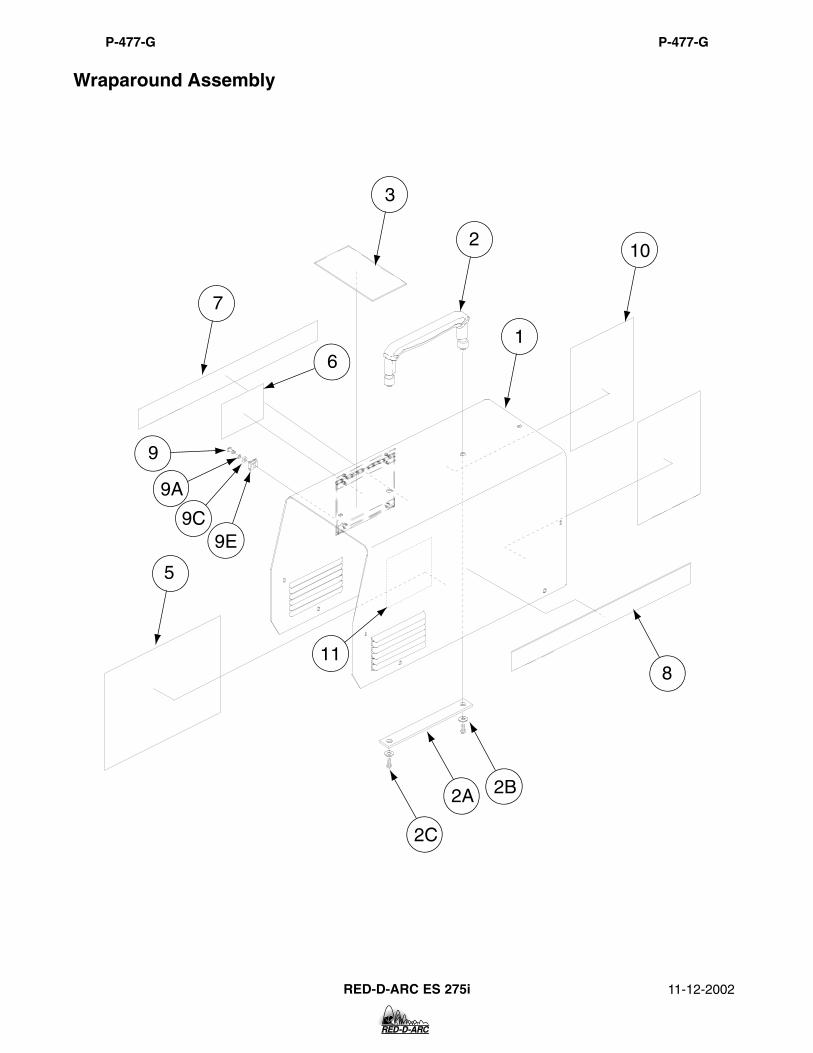
1 Wraparound & Door Assembly L11987-1 1 X2 Handle Assembly S18170 1 X2A Handle Support S25633 1 X2B Plain Washer S9262-98 2 X2C 1/4-20 x .375 HHCS CF000170 2 X3 Warning Decal M16196 1 X4 Reconnect Instructions (Not Shown) S25572 1 X5 Wiring Diagram G4365-2 1 X6 Warning Decal S20900-2 1 X7 Side Decal (G4364-8) G4364 1 X8 Side Decal (G4364-8) G4364 1 X9 Stud S24815-1 2 X9A Sealing Washer S24816-1 2 X9B Ejector Spring (Not Shown) S24817-1 2 X9C Nylon Wear Washer S24818-1 2 X9D Retainer (Not Shown) S24819-1 2 X9E Receptacle S24820-1 2 X10 E2521/1-.010-6.00-9.00 Cl001262 2 X11 E2521/1-.010-4.25-4.25 Cl001056 1 X12 #10-24 x .50 HHCS (Not Shown) S24739-2 10 X
* Recommended Spare Part
11-12-2002RED-D-ARC ES 275i
Use only the parts marked “x” in the column under theheading number called for in the model index page.
# Indicates a change this printing.
P-477-G.1
ITEM DESCRIPTION PART NO. QTY. 1 2 3 4 5 6 7 8 9
P-477-G.1

RED-D-ARC ES 275i
NOTES

NOTES
ES 275i

NOTES
ES 275i

ES 275i
NOTES

WARNING
AVISO DEPRECAUCION
ATTENTION
WARNUNG
ATENÇÃO
Spanish
French
German
Portuguese
Japanese
Chinese
Korean
Arabic
READ AND UNDERSTAND THE MANUFACTURER’S INSTRUCTION FOR THIS EQUIPMENT AND THE CONSUMABLES TO BEUSED AND FOLLOW YOUR EMPLOYER’S SAFETY PRACTICES.
SE RECOMIENDA LEER Y ENTENDER LAS INSTRUCCIONES DEL FABRICANTE PARA EL USO DE ESTE EQUIPO Y LOSCONSUMIBLES QUE VA A UTILIZAR, SIGA LAS MEDIDAS DE SEGURIDAD DE SU SUPERVISOR.
LISEZ ET COMPRENEZ LES INSTRUCTIONS DU FABRICANT EN CE QUI REGARDE CET EQUIPMENT ET LES PRODUITS AETRE EMPLOYES ET SUIVEZ LES PROCEDURES DE SECURITE DE VOTRE EMPLOYEUR.
LESEN SIE UND BEFOLGEN SIE DIE BETRIEBSANLEITUNG DER ANLAGE UND DEN ELEKTRODENEINSATZ DES HER-STELLERS. DIE UNFALLVERHÜTUNGSVORSCHRIFTEN DES ARBEITGEBERS SIND EBENFALLS ZU BEACHTEN.
� Do not touch electrically live parts orelectrode with skin or wet clothing.
� Insulate yourself from work andground.
� No toque las partes o los electrodosbajo carga con la piel o ropa moja-da.
� Aislese del trabajo y de la tierra.
� Ne laissez ni la peau ni des vête-ments mouillés entrer en contactavec des pièces sous tension.
� Isolez-vous du travail et de la terre.
� Berühren Sie keine stromführendenTeile oder Elektroden mit IhremKörper oder feuchter Kleidung!
� Isolieren Sie sich von denElektroden und dem Erdboden!
� Não toque partes elétricas e elec-trodos com a pele ou roupa molha-da.
� Isole-se da peça e terra.
� Keep flammable materials away.
� Mantenga el material combustiblefuera del área de trabajo.
� Gardez à l’écart de tout matérielinflammable.
� Entfernen Sie brennbarres Material!
� Mantenha inflamáveis bem guarda-dos.
� Wear eye, ear and body protection.
� Protéjase los ojos, los oídos y elcuerpo.
� Protégez vos yeux, vos oreilles etvotre corps.
� Tragen Sie Augen-, Ohren- und Kör-perschutz!
� Use proteção para a vista, ouvido ecorpo.

WARNING
AVISO DEPRECAUCION
ATTENTION
WARNUNG
ATENÇÃO
Spanish
French
German
Portuguese
Japanese
Chinese
Korean
Arabic
LEIA E COMPREENDA AS INSTRUÇÕES DO FABRICANTE PARA ESTE EQUIPAMENTO E AS PARTES DE USO, E SIGA ASPRÁTICAS DE SEGURANÇA DO EMPREGADOR.
� Keep your head out of fumes.� Use ventilation or exhaust to
remove fumes from breathing zone.
� Los humos fuera de la zona de res-piración.
� Mantenga la cabeza fuera de loshumos. Utilice ventilación oaspiración para gases.
� Gardez la tête à l’écart des fumées.� Utilisez un ventilateur ou un aspira-
teur pour ôter les fumées des zonesde travail.
� Vermeiden Sie das Einatmen vonSchweibrauch!
� Sorgen Sie für gute Be- undEntlüftung des Arbeitsplatzes!
� Mantenha seu rosto da fumaça.� Use ventilação e exhaustão para
remover fumo da zona respiratória.
� Turn power off before servicing.
� Desconectar el cable de ali-mentación de poder de la máquinaantes de iniciar cualquier servicio.
� Débranchez le courant avant l’entre-tien.
� Strom vor Wartungsarbeitenabschalten! (Netzstrom völlig öff-nen; Maschine anhalten!)
� Não opere com as tampas removidas.� Desligue a corrente antes de fazer
serviço.� Não toque as partes elétricas nuas.
� Do not operate with panel open orguards off.
� No operar con panel abierto oguardas quitadas.
� N’opérez pas avec les panneauxouverts ou avec les dispositifs deprotection enlevés.
� Anlage nie ohne Schutzgehäuseoder Innenschutzverkleidung inBetrieb setzen!
� Mantenha-se afastado das partesmoventes.
� Não opere com os paineis abertosou guardas removidas.

• Sales and Service through Subsidiaries and Distributors Worldwide •
Cleveland, Ohio 44117-1199 U.S.A. TEL: 216.481.8100 FAX: 216.486.1751 WEB SITE: www.lincolnelectric.com
• World's Leader in Welding and Cutting Products •