Embed Size (px)
Citation preview

CROSS FLOW PLATE HEAT EXCHANGERS
RECUPRECUP/LC
HEAT RECOVERY VENTILATORS

2
HEAT RECOVERY UNITS
COMFORT AND ENERGY SAVING
With energy, heat or cold recuperators it will no longer be a problem to combine
the ventilation with the air-conditioning or heating systems. Apart from
recovering and conserving energy, the recuperators, with their entry filters and
air outlet, will make the environment clean and comfortable.
OPERATIONA heat recovery ventilator operates by means of the combination of two centrifugal fans with a low sound level, one of which extracts the stale air from the interior of the premises to the outside, and the other drives fresh air from outside into the premises.
The two circuits cross, without mixing, in a heat exchanger, in which the heat from the outgoing air is transferred to the fresh air from the outside, heating it up.
HEAT EXCHANGER
FANS
FILTERS
16º SUPPLY AIRFLOW
20º OUTGOING AIR
4ºEXHAUST AIRFLOW
0ºFRESH AIR
3
POSITION OF FILTER STAGES
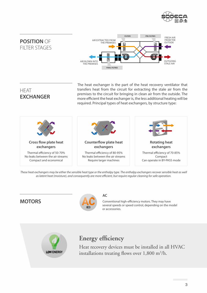
Cross flow plate heat exchangers
Thermal efficiency of 50-70%No leaks between the air streams
Compact and economical
Rotating heat exchangers
Thermal efficiency of 70-85%Compact
Can operate in BY-PASS mode
Counterflow plate heat exchangers
Thermal efficiency of 80-95%No leaks between the air streams
Require larger machines
The heat exchanger is the part of the heat recovery ventilator that transfers heat from the circuit for extracting the stale air from the premises to the circuit for bringing in clean air from the outside. The more efficient the heat exchanger is, the less additional heating will be required. Principal types of heat exchangers, by structure type:
These heat exchangers may be either the sensible heat type or the enthalpy type. The enthalpy exchangers recover sensible heat as well as latent heat (moisture), and consequently are more efficient, but require regular cleaning for safe operation.
HEAT EXCHANGER
Energy efficiencyHeat recovery devices must be installed in all HVAC installations treating flows over 1,800 m3/h.
MOTORSAC
Conventional high-efficiency motors. They may have several speeds or speed control, depending on the model or accessories.
FRESH AIRFROM THE OUTSIDE
FILTERS PRE-FILTRES
OUTGOING STALE AIR
FINAL FILTRES
AIR EXTRACTED FROM THE PREMISES
AIR BLOWN INTO THE PREMISES

4
Wall-mountedDomestic machines for heat recovery from small rooms.
In a false ceilingLow-profile machines with access to components from the sides or underneath.
Roof-mountedEquipment that can work outside, with access to components from the sides. They may require accessories, such as covers or hoods for protection against rain and other weather elements.
In the technical roomCompact machines with side access to components. These machines usually have inlets and outlets on the top.
Some ventilators have versions or accessories with heating or cooling coils to heat or cool the air supply. This is very common in heat recov-ery ventilators, although it may also be applied to filtration units. The commonest options are as follows:
Some units have components to check on head loss, in order to optimise filter replacement.
· Pressure inlets: Small air inlets that allow head loss of filter stages to be detected.
· Differential manometer: Visual detection of head loss per filter stage.
· Pressure switch: Pressure switch that switches an electrical circuit on of off on the basis of the filter head loss.
Each filtration stage has one or more filters of the same efficiency, as required for each application.
Depending on their configuration, the units may incorporate:
· Stage with pre-filters that ensure correct operation of the equipment, depending on the requirements of the installation, the efficiencies may be: G4, F6, F7.
· Stages with final filters that guarantee the quality of the air supplied to the premises; the efficiencies are usually of the following types: F6, F7, F8, F9, CA (active carbon gas filters) or even HEPA filters, depending on the IDA/ODA category.
The filters retain particles that affect air quality, and must be replaced after a period of use. Filter head loss increases progressively over time.
TYPES OF INSTALLATION
CLIMATE CONTROL OPTIONS
FILTERS
Environmental version
No heating/cooling.
Electric battery cooling
Supply of heating by electrically heated coils.
Version with water coils
Provides climate control by coils containing hot or cold water.

5
Configurable heat recovery units with cross-flow panels, for horizontal (H) installation
RECUP
Order code
H: Horizontal configuration
SizeRECUP: Configurable heat recovery units with cross-flow panels
A-F: Nozzle position (Standard C or B based on model)
F6 filter
RECUP 20 H C F6 60Hz
Features:• Cross flow plate heat exchanger with
an efficiency of between 50%-70%.• Possibility of configuration with
different nozzle positions.• Built-in filters, classes F6. Other
combinations available on request.• Box made of galvanised steel with
built-in acoustic insulation.
Construction:• Galvanised sheet steel structure.• Entry and exit nozzles with water-tight
gaskets.
• Interchangeable nozzles.• Access doors to facilitate maintenance
and cleaning.
Versions:• Horizontal (H).• Non-heating: Renewal of air
without supplying heat (S).
On request: • Different stages of filtration.
Technical characteristics
Model Speed Voltage Current Motor power
Maximumairflow F6
Irradiated SPL
FilterEN 779 Weight
(r/min) (V) (A) (W) (m3/h) dB(A) (Kg)
RECUP-12-H 1710 1x220 2x2.00 2x450 1300 53 F6 67RECUP-20-H 1620 1x220 2x2.00 2x450 2050 48 F6 86RECUP-30-H 1500 1x220 2x5.40 2x600 3150 52 F6 112RECUP-40-H 1080 3x380 2x3.60 2x1100 4250 46 F6 167RECUP-50-H 1536 3x380 2x3.50 2x1500 5350 54 F6 182RECUP-60-H 1740 3x380 2x4.83 2x2200 6150 56 F6 205

6
Configurations
Standard supply C configuration. Except model 12, B configuration.
Configuration A
FiltroFiltro
SUP
EHA
ODA
ETA
ODA
ETA SUP
EHA
FiltroFiltro
SUP
EHAODA
ETA
FiltroFiltro
EHA
SUPETA
ODA
FiltroFiltro
ETA
ODA
EHA
SUP
FiltroFiltro
EHA
ETA
ODA
SUP
FiltroFiltro
Configuration B Configuration C Configuration D Configuration E Configuration F
ODA: Fresh air from outside / SUP: Air blown into the premises / EHA: Stale air outlet / ETA: Air extracted from the premises
Dimensions in mm
RECUP-12-H 415 1000 1000 315 260.4 479.2 260.4 207.5 207.5RECUP-20-H 490 1050 1050 315 251 548 251 280 280RECUP-30-H 590 1100 1200 315 266 668 266 350 350RECUP-40-H 670 1500 1500 450 350 800 350 368 368RECUP-50/60-H 850 1500 1700 450 351.5 997 351.5 424.5 424.5
Model A B L øD H1 H2 H3 W W1
RECUP-12-H 415 1000 1525 1000 315 260.4 479.2 260.4 207.5 207.5 207.5 207.5RECUP-20-H 490 1050 1575 1050 315 251 548 251 250 280 280 280RECUP-30-H 590 1100 1625 1200 315 266 668 266 320 350 350 350RECUP-40-H 670 1500 2025 1500 450 350 800 350 368 368 368 368RECUP-50/60-H 849 1500 2025 1700 450 351.5 997 351.5 424.5 424.5 424.5 424.5
Model A B B1 L øD H1 H2 H3 W W1 W2 W3
RECUP H F6
RECUP H F6+F8
On request

7
Characteristic Curves
Accessories
CJFILTER SI-PRESIÓN INT TEJPRESOSTATO BANCADA GENERAL
SILENT-BLOCKSFILTROS VIS
Acoustic features
RECUP-12 54 56 49 52 54 50 45 38RECUP-20 49 51 44 47 49 45 40 33RECUP-30 54 56 50 51 48 43 35 31
Model 63 125 250 500 1000 2000 4000 8000 Model 63 125 250 500 1000 2000 4000 8000
Sound power spectrum Lw(A) in dB(A) per Hz frequency band
The indicated values are determined by measuring the sound power level in dB(A) obtained in a free field at a distance of no less than 1.5 m from the equipment.
RECUP-40 49 51 43 37 36 30 29 15RECUP-50 57 59 50 44 42 36 37 22RECUP-60 59 61 52 46 44 38 39 24
On request

8
Configurable heat recovery units with crossed flow plates for horizontal installation
RECUP/LC
Order code
A-F: Inlet and outlet configuration
SizeRECUP/LC: Configurable heat recovery units with crossed flow plates for horizontal installation
F7 filterF7+F9 filters
RECUP/LC 20 C F7
Features:• Cross flow plate heat exchanger with
an efficiency of between 50%-70%.• Multi-position configurable outlets.• Built-in filters, classes F7. Other
combinations available on request.• Designed for installation in a false
ceiling.• Access to filters and components
via front panel.
Construction:• Galvanised sheet steel structure with
soundproofing.• Interchangeable inlets and outlets
with watertight joints.• Access doors to facilitate maintenance
and cleaning.• Condensate drain integrated in the
access cover.
On request: • F7+F9 filters
Technical characteristics
Model Speed Current (A) Voltage Installedpower
Maximumairflow NPS Weight
(r/min) 230V 400V (V) (W) (m3/h) dB(A) (Kg)
RECUP/LC-05-F7 2928 2x0.45 - 1x220 2x100 540 45 26RECUP/LC-08-F7 2928 2x0.45 - 1x220 2x100 780 53 30RECUP/LC-12-F7 2928 2x0.72 - 1x220 2x150 1080 56 34RECUP/LC-20-F7 2424 2x0.90 - 1x220 2x195 1900 51 63RECUP/LC-30-F7 3300 2x2.70 - 1x220 2x550 2850 54 72RECUP/LC-45-F7 1680 - 2x2.80 3x380 2x1100 4500 53 177RECUP/LC-60-F7 2550 - 2x4.80 3x380 2x2200 5700 57 207RECUP/LC-05-F7+F9 2928 2x0.45 - 1x220 2x40 380 45 26RECUP/LC-08-F7+F9 2928 2x0.45 - 1x220 2x40 570 53 30RECUP/LC-12-F7+F9 2928 2x0.72 - 1x220 2x150 790 56 34RECUP/LC-20-F7+F9 2424 2x0.90 - 1x220 2x195 1350 51 63RECUP/LC-30-F7+F9 3300 2x2.70 - 1x220 2x550 2050 54 72RECUP/LC-45-F7+F9 1680 - 2x2.80 3x380 2x1100 4050 53 177RECUP/LC-60-F7+F9 2550 - 2x4.80 3x380 2x2200 5000 57 207

9
Dimensions in mm
Acoustic features
Sound power spectrum Lw(A) in dB(A) per Hz frequency band
Maintenance access
RECUP/LC-05 310 575 575 150 131 312 131 164 164RECUP/LC-08 310 650 650 250 160 330 160 164 164RECUP/LC-12 330 700 700 250 165 370 165 174 174RECUP/LC-20 504 900 900 355 240 420 240 252 252RECUP/LC-30 504 900 900 355 240 420 240 252 252RECUP/LC-45 580 1520 1520 450 310 900 310 290 290RECUP/LC-60 580 1520 1520 450 310 900 310 290 290
Model A B L D H1 H2 H3 W W1
Model 63 125 250 500 1000 2000 4000 8000 Model 63 125 250 500 1000 2000 4000 8000RECUP/LC-05 30 42 45 57 53 50 40 37RECUP/LC-08 38 50 53 65 61 58 48 45RECUP/LC-12 41 53 56 68 64 61 51 48RECUP/LC-20 38 50 53 65 61 58 48 45
The indicated values are determined by measuring the sound power level in dB(A) obtained in a free field at a distance of no less than 3 m from the equipment.
RECUP/LC-30 43 56 66 69 67 62 54 45RECUP/LC-45 53 62 65 62 61 60 56 54RECUP/LC-60 51 68 58 59 62 62 60 56
Configurations
Standard delivery configuration C. All models allow inlet and outlet configuration directly at the installation premises, except the 45, 60 model which only allows the air inlet configuration.
Configuration A
FiltroFiltro
SUP
EHA
ODA
ETA
ODA
ETA SUP
EHA
FiltroFiltro
SUP
EHAODA
ETA
FiltroFiltro
EHA
SUPETA
ODA
FiltroFiltro
ETA
ODA
EHA
SUP
FiltroFiltro
EHA
ETA
ODA
SUP
FiltroFiltro
Configuration B Configuration C Configuration D Configuration E Configuration F
ODA: Fresh air from outside / SUP: Air blown into the premises / EHA: Stale air outlet / ETA: Air extracted from the premises.Top view diagrams, for placement of the equipment in the ceiling. With maintenance access in the bottom panel.

10
Characteristic Curves
SI-PRESIÓN
Accessories
CJFILTER INTPRESOSTATO SILENT-BLOCKSFILTROS

11

www.sodeca.com
CHILESodeca Ventiladores, SpA.Sra. Sofía OrmazábalSanta Bernardita 12.005(Esquina con Puerta Sur)Bodegas 24 a 26, San Bernado, Santiago, CHILETel. +56 22 840 [email protected]
COLOMBIASodeca Latam, S.A.S.Sra. Luisa Stella PrietoCalle7 No. 13 A-44Manzana 4 Lote1, MontanaMosquera, CundinamarcaBogotá, COLOMBIATel. +57 1 756 [email protected]
PERUSodeca Perú, S.A.C.Sr. Jose Luis JiménezC/ Mariscal Jose Luis deOrbegoso 331. Urb. El pino. 15022 , San Luis. Lima, PERÚTel. +51 1 326 24 24Cel. +51 [email protected]
AMERICA
HEADQUARTERSSodeca, S.L.U.
Pol. Ind. La BarriconaCarrer del Metall, 2E-17500 RipollGirona, SPAINTel. +34 93 852 91 11Fax +34 93 852 90 42General sales: [email protected] sales: [email protected]
PRODUCTION PLANTSodeca, S.L.U.
Ctra. de Berga, km 0,7E-08580 Sant Quirze de BesoraBarcelona, SPAINTel. +34 93 852 91 11Fax +34 93 852 90 42General sales: [email protected] sales: [email protected]
Ref.
09/2
020