Embed Size (px)
DESCRIPTION
B. Khuri-Yakub, A. Ergun, G. Yaralioglu Keywords-reconfigurable; annular; array; cMUT; ASIC; switch matrix; dynamic; phased; real-time GE Global Research Niskayuna, NY-USA [email protected] Figure 1. Reconfigurable Array Concept: Cells are hardwired together to form larger acoustic subelements. Thousands of subelements are connected or disconnected to each other and to system channels via an underlying switch matrix thus enabling electronically changing apertures.
Citation preview

Reconfigurable Arrays for Portable Ultrasound
R. Fisher, K. Thomenius, R. Wodnicki, R. Thomas, S. Cogan, C. Hazard, W. Lee, D. Mills
GE Global Research Niskayuna, NY-USA [email protected]
B. Khuri-Yakub, A. Ergun, G. Yaralioglu E. L. Ginzton Laboratory
Stanford University Stanford, CA-USA
Abstract—A collaborative effort is aimed at the development of reconfigurable array technology. The goal is to enable innovative medical ultrasound imagers ideally suited for portable ultrasound and applications such as remote emergency medicine and combat casualty care. Success depends on developing several technologies, the first of which is capacitive micromachined ultrasound transducers (cMUTs). The monolithic nature of cMUTs facilitates close connection with microelectronics. Thus a second technology under development is a switch matrix application specific integrated circuit (ASIC) that will enable the changing of interconnect between cMUT cells. The reconfigurable array concept arises from this ability to dynamically combine cMUT cells to form ideal apertures for a given imaging target (e.g. annular and phased apertures of various ring widths) and to move these apertures across the reconfigurable array plane [1-4]. Two central hypotheses are being tested: (1) the reconfigurable array can acquire acoustic pulse-echo data in a manner equivalent or superior to today’s 1D piezoceramic arrays (2) reconfigurable array technology will enable highly portable ultrasound platforms.
Keywords-reconfigurable; annular; array; cMUT; ASIC; switch matrix; dynamic; phased; real-time
I. INTRODUCTION Identification of internal bleeding in emergency patients or
combat casualties is critical within the first hour after injury. To achieve speed in bleed localization a highly portable, high image quality, ultrasound system is desired. Laptop sized scanners are now readily available in the marketplace and promoted for niche applications especially where portability is important, such as general practice physician offices or remote area services, emergency rooms, and even ambulance care. But these devices generally have compromised beamformation
because of choices for reduced channel count, use of synthetic aperture methods, lower frame rates, and lower number of A/D converter bits for the digitization process in order to reduce system size. It is of further concern that the clinical user base for these portable systems is less experienced than radiologists or sonographers in full-time practice, particularly since there is an art to achieving clinical utility in situations where image data acquisition is suboptimal.
The proposed solution is to develop a “reconfigurable array” system that provides high-end image quality despite significantly reduced channel count. In the usual ultrasound imager design, each array element in the active aperture is associated with a system beamforming channel with its A/D converter and beamforming electronics. The reconfigurability concept in which array elements are formed by electronically combining smaller transducer subelements (see Fig. 1) removes this beamforming redundancy. cMUTs are attractive for implementation of a reconfigurable array because they are formed using microelectronic processes and thus very apt to integration with front end electronics such as switching, pulser, and pre-amp circuitry. In addition, the high fractional bandwidth of cMUTs can be used to achieve image quality improvements (spatial resolution and harmonic imaging).
An appealing approach to reconfiguring such an array is to form an annular aperture. The acoustic fields generated by annular arrays are considered to be superior largely because of the symmetry. Thus axisymmetric dynamic focusing can be achieved without system changes. As a result, annular arrays have been considered to provide better image quality, albeit at the disadvantage of requiring a mechanical mover to acquire 2D image data. With the reconfigurable array, electronically scanned annular arrays can be attained for the first time.
Some effort supported by US Army Medical Research Acquisition Activity DAMD17-02-0181, 820 Chandler Street, Fort Detrick, MD 21702-5014. The content of the information does not necessarily reflect the position or the policy of the Government and no official endorsement should be inferred.
Some effort described was supported by Grant Number R01 EB002485 from NIBIB. Contents of this publication are solely the responsibility of the authors and do not necessarily represent the official views of NIH.
Figure 1. Reconfigurable Array Concept: Cells are hardwired together to form larger acoustic subelements. Thousands of subelements are connected or disconnected to each other and to system channels via an underlying switch matrix thus enabling electronically changing apertures.
0-7803-9383-X/05/$20.00 (c) 2005 IEEE 495 2005 IEEE Ultrasonics Symposium

II. RECONFIGURABLE ARRAY TECHNOLOGIES The first steps to prove that reconfigurable arrays can
provide high-end image quality with significantly reduced channel count have been taken by demonstrating key technologies. The first was the development of a 20-ring static annular cMUT array with similar performance to a conventional piezoceramic linear array. The second was the fabrication of a switch matrix ASIC that interconnects a 16 by 16 array of transducer elements to reconfigure the acoustic pattern in real-time with only 20 channels.
A. cMUT Annular Array In order to demonstrate that this new structure could
perform in at least an equivalent fashion to a conventional array, several simulations have been run. The graphs of Fig. 2 show lateral beam profiles for different subelement sizes and how they compare with a linear array. For cases shown, the annular array beamshape is nearly equivalent to a linear array in the imaging plane. As expected due to the circular symmetry, the annular array is far superior in the elevation plane.
An important factor in the quality of an ultrasound image is the sidelobe performance of the array. This aspect of the array design was tested against key array design parameters such as subelement size. Fig. 3 results show satisfactory performance for the 200um and 250um sizes, although some compromise is evident. Further results from these initial simulation studies are given in [2].
0 1 2 3 4 5-80
-60
-40
-20
0
Radial Distance (mm)
Nor
mal
ized
Am
plitu
de (
dB)
A) F=10mm
300um
250um
200umLinear
Lin Elev
0 1 2 3 4 5-80
-60
-40
-20
0
Radial Distance (mm)
Nor
mal
ized
Am
plitu
de (
dB)
B) F=40mm
Figure 2. Effect of sub-element size on main beam for 200um, 250um,
300um sub-element sizes. Transmit focal points at 10 and 40 mm shown. Linear array radiation patterns included for comparison.
0 20 40 60-100
-50
0
Radial Distance (mm)
Nor
mal
ized
Am
plitu
de (
dB)
A) F=10mm300um
250um
200umLinear
Lin Elev
0 20 40 60-100
-80
-60
-40
-20
0
Radial Distance (mm)N
orm
aliz
ed A
mpl
itude
(dB
)
B) F=40mm
Figure 3. Effect of subelement size on secondary lobes for 200um, 250um,
300um sub-element sizes. Transmit focal points at 10 and 40 mm shown. Linear array radiation patterns included for comparison.
A new tool that produces increasingly realistic computer simulations of the acoustic fields generated by reconfigurable arrays has been developed. The main focus in this work has been the careful analysis of the configuration of the array subelements into elements, the influence of electrical loading, and the impact of resulting non-ideal acoustic fields. Field II from Jorgen Jensen at the Technical University of Denmark is being used as the acoustic calculation engine [5].
Fig. 4 shows two annular designs (20 rings and 32 rings). The tool generates these apertures using input variables such as number of rings, subelement pitch, subelement kerf, aperture width, steering angle, and focal depth. Next, switch states for the switch matrix ASIC are generated in order to configure the desired annular aperture on the reconfigurable array. Incorporated into the tool is the ability to analyze the role of missing subelements and possible delay errors associated with the circuitry. The acoustic performance of an aperture can then be simulated with Field II to generate 2D beam plots that can then be used to estimate the main lobe performance and secondary lobe levels. Simulated ultrasound images can also be produced to further assess the expected image quality from a given aperture.
The beam profiles of Fig. 5 were generated using these tools. The images are one-way beam profiles assuming, 150um or 200um subelement size, 40um subelement kerf, 20mm aperture width, focal depth of 50mm and a 2-cycle, 5MHz pulse. The annular array with 32 rings has better sidelobe
0-7803-9383-X/05/$20.00 (c) 2005 IEEE 496 2005 IEEE Ultrasonics Symposium

performance, especially in the nearfield. Since the aperture width is the same for both cases, the ring width for the 32-ring case is narrower and thus the elemental granularity with respect to delays is better. Using a finer subelement pitch of 150um shows further improvement, though the results are not as dramatic, since the ring width remains the same, however each ring’s borders are smoother due to the smaller subelements. As is evident, this tool is ideal for the design of the reconfigurable apertures to meet application requirements and for assessing array hardware limitations.
Figure 4. 20-ring and 32-ring apertures were generated by the reconfigurable array simulation tool assuming a 20mm aperture width, and subelement pitch
of 200um, and equal width rings (~7800 subelements)
Based on the modeling results, array geometry such as number of rings, size of subelement, and width of rings were specified for a given application. Stanford then designed and fabricated a 20-ring static cMUT annular array with
subelements sized at (280um)2 that was integrated with a LOGIQ 700 scanner. Fig. 6 shows the array, which has a small wedge to bring out electrical connections from each ring. The image in fig. 7 was obtained by mechanically moving the array and obtaining M-mode scans while operating the array at 6.5MHz, 3cm focal depth, and 60dB dynamic range. This image shows similar performance of the cMUT annular array as compared with a conventional PZT ultrasound probe, however, with 6 times lower channel count.
Figure 6. 20-ring static annular cMUT array; close-up of the electrical connect from the rings that removes a small wedge of acoustic area; close up
of the array showing the center “button”.
Figure 7. This image was taken with the 20-ring static annular cMUT. As can be seen, even the 2 mm spheres are clearly visible; this is only seen with
conventional arrays at the elevation focus.
B. Switch Matrix Electronics The first switch matrix ASIC contains a 16 by 16 array of
unit cells with a total of 1,024 switches and their associated logic in a 5mm by 6.4mm chip. Figure 8 shows an 8 by 8 example of the core of the layout. Each row of cells shares high voltage analog signal lines, while each column of cells shares a
a) b) c)a) b) c) Figure 5. One way beam profiles for 20 mm aperture width and a) 20 rings and 200 um subelement pitch, b) 32 rings and 200 um subelement pitch, c) 32
rings and 150 um subelement pitch
4 mm 2 mm
0-7803-9383-X/05/$20.00 (c) 2005 IEEE 497 2005 IEEE Ultrasonics Symposium
digital control bus. Each cell also contains a signal pad for probing of the center point of the 4 switches and for connection to a transducer subelement. Digital circuitry is used to control the state of the switches. Power bus lines are routed down into the array from the pad ring at the chip edge. The analog data from these cells is read out along the analog data lines.
Figure 8. Each cell of the switch matrix ASIC contains 3 matrix switches for connection between transducer subelements, 1 access switch for connection to a system channel, digital logic to set switch states, and a signal pad which will
be connected to a transducer subelement.
Individual cells are programmed and selected using digital data lines. This digital data is programmed into the array prior to transmit to reconfigure the switch matrix. There are three matrix switches that disconnect or connect one transducer subelement to another and one access switch to connect a given subelement to a system channel. Thus by setting the switches in a specific pattern one can electronically configure elements and apertures.
III. PROOF OF RECONFIGURABILITY CONCEPT The first prototype of a switch matrix ASIC has been built,
integrated with a piezoceramic array, and tested for its ability to translate a 2D aperture on the array surface. Fig. 9 shows the switch matrix ASIC with its 16 by 16 matrix of switch cells and 1,024 total switches. Fig. 10 shows its integration with a 256-subelement piezoceramic array.
Figure 9. A switch matrix ASIC with a 16 by 16 array of electronic subelements containing 1,024 switches
To test out the functionality of the switch matrix/transducer assembly, the integrated device was placed in a water tank, an active aperture was formed by selection of a pattern of switches, and the resulting acoustic field was measured by a hydrophone. Next the pattern was translated to a new location
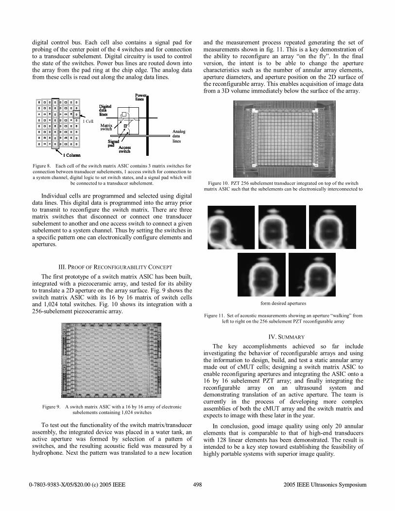
and the measurement process repeated generating the set of measurements shown in fig. 11. This is a key demonstration of the ability to reconfigure an array “on the fly”. In the final version, the intent is to be able to change the aperture characteristics such as the number of annular array elements, aperture diameters, and aperture position on the 2D surface of the reconfigurable array. This enables acquisition of image data from a 3D volume immediately below the surface of the array.
Figure 10. PZT 256 subelement transducer integrated on top of the switch matrix ASIC such that the subelements can be electronically interconnected to
form desired apertures
Figure 11. Set of acoustic measurements showing an aperture “walking” from left to right on the 256 subelement PZT reconfigurable array
IV. SUMMARY The key accomplishments achieved so far include
investigating the behavior of reconfigurable arrays and using the information to design, build, and test a static annular array made out of cMUT cells; designing a switch matrix ASIC to enable reconfiguring apertures and integrating the ASIC onto a 16 by 16 subelement PZT array; and finally integrating the reconfigurable array on an ultrasound system and demonstrating translation of an active aperture. The team is currently in the process of developing more complex assemblies of both the cMUT array and the switch matrix and expects to image with these later in the year.
In conclusion, good image quality using only 20 annular elements that is comparable to that of high-end transducers with 128 linear elements has been demonstrated. The result is intended to be a key step toward establishing the feasibility of highly portable systems with superior image quality.
1 Cell
1 Column
Matrix
Access switch
Signalpad
data
Power lines
Digitaldatalines
1 Cell
1 Column
1 Cell
1 Column
switch
Access switch
Signalpad
Analog
lines
Power lines
Digitaldatalines
1 Cell
1 Column
1 Cell
1 Column
Matrix
Access switch
Signalpad
data
Power lines
Digitaldatalines
1 Cell
1 Column
1 Cell
1 Column
switch
Access switch
Signalpad
Analog
lines
Power lines
Digitaldatalines
0-7803-9383-X/05/$20.00 (c) 2005 IEEE 498 2005 IEEE Ultrasonics Symposium

REFERENCES
[1] K. Thomenius, R. Fisher, D. Mills, R. Wodnicki, C. Hazard, and L.
Smith, “Mosaic arrays using micromachined transducers,” US Patent #6,865,140, March 8, 2005.
[2] C. Hazard, R. Fisher, D. Mills, L. Smith, K. Thomenius, and R.Wodnicki, “Annular array beamforming for 2D arrays with reduced system channels,” 2003 IEEE ultrasonics symposium, October 2003, vol. 2, pp. 1859-1862.
[3] D. Bailey, J. Meyyappan, and G. Wade, “A computer controlled transducer for real-time three-dimensional imaging,” Acoustical Imaging, vol. 18, pp. 543-552.
[4] R. Bele, “Echography probe and apparatus incorporating such a probe,” US Patent #4,641,660, February 10, 1987.
[5] J.A. Jensen and N. B. Svendsen: Calculation of pressure fields from arbitrarily shaped, apodized, and excited ultrasound transducers, IEEE Trans. Ultrason., Ferroelec., Freq. Contr., 39, pp. 262-267, 1992.
0-7803-9383-X/05/$20.00 (c) 2005 IEEE 499 2005 IEEE Ultrasonics Symposium