Embed Size (px)
Citation preview
Recommended Acceptance Testing Procedure for Network Enabled Training Simulators
Peter Ross and Peter Clark
Air Operations Division Defence Science and Technology Organisation
DSTO-TR-1768
ABSTRACT Over the next ten years the Department of Defence will acquire many new platform training simulators that will support distributed team training, otherwise known as network-enabled training simulators. These include the AP-3C Operational Mission Simulator and Advanced Flight Simulator, Airborne Early Warning & Control Operational Mission Simulator, C-130H and C-130J flight simulators, Armed Reconnaissance Helicopter (ARH) simulator, Super Seasprite simulator, and FFG Upgrade Onboard Training System (OBTS) and team trainer. It is necessary to test these simulators for compliance to the relevant distributed simulation standards to ensure network interoperability. However, at present there is no uniform testing procedure. This report details a recommended acceptance testing procedure for network-enabled simulators and provides test cases for the Distributed Interactive Simulation standard.
RELEASE LIMITATION
Approved for public release
Published by Air Operations Division DSTO Defence Science and Technology Organisation 506 Lorimer St Fishermans Bend, 3207 Australia Telephone: (03) 9626 7000 Fax: (03) 9626 7999 © Commonwealth of Australia 2005 AR-013-491 August 2005 APPROVED FOR PUBLIC RELEASE
Recommended Acceptance Testing Procedure for Network Enabled Training Simulators
Executive Summary Over the next ten years the Department of Defence will acquire many new platform training simulators that will support distributed team training, otherwise known as network-enabled training simulators. This form of training is made possible through the use of distributed simulation standards. It is necessary to ensure that new simulators comply to the relevant distributed simulation standards during acceptance testing. However, at present there is no uniform procedure for acceptance testing of network-enabled simulators. This report presents an acceptance testing procedure that is based on the authors’ prior experience with training simulator testing. It introduces distributed simulation concepts in relation to platform training simulators. The acceptance testing procedure, which consists of planning, test activity and documentation stages, is described. Test cases for the Distributed Interactive Simulation (DIS) standard are provided, and test equipment and known ambiguities with the DIS protocol are also discussed. The procedure presented in this report will facilitate acceptance and interoperability testing conducted under the NAV 04/026 “Air Maritime Team Training” task. Present year-one milestones include testing of, the AP-3C Advanced Flight Simulator; FFG Upgrade Team Trainer; FFG-UP On Board Training System; and Super Seasprite simulator. Whilst test cases are provided for the DIS standard, the procedure is suitable for other distributed simulation standards, such as the High Level Architecture.

Authors
Peter Ross Air Operations Division Peter Ross graduated from RMIT University in 2001 with a Bachelor of Applied Science, majoring in computer science. Mr Ross joined the Air Operations Division in 2003, and works in the Advanced Distributed Simulation Laboratory; researching communications and interoperability issues in the area of Advanced Distributed Simulation. Mr Ross is a member of the SISO DIS Product Development Group. Prior to joining DSTO, Mr Ross worked as a contractor within AOD.
____________________ ________________________________________________
Peter Clark Air Operations Division Dr Peter Clark is a Senior Research Scientist (Executive Level 2) with the Air Operations Division of DSTO. He graduated from the Australian National University (ANU) in Canberra with a BSc (Hons) in 1978, and a PhD in Physics in 1981. He joined the Australian Defence Department in Canberra in 1982 as a Research Scientist. In 1989 he was appointed for a five year period as the Scientific Adviser to Army’s HQ Training Command in Sydney, where he enhanced Army’s exploitation of simulation for training, and was awarded an Army Commendation. In 1994 he was appointed as a Senior Research Scientist with DSTO’s Air Operations Division, based in Melbourne, where he has worked on both Navy and Air Force simulation projects. Dr Clark has over 23 years experience in simulation research, with an emphasis on Human-in-the-Loop real-time simulation, computer-generated forces, and the technologies associated with Advanced Distributed Simulation. Currently he is the Task Manager for "Air-Maritime Team Training" which is implementing the JOint Air Navy Networking Environment (JOANNE) to establish the use of distributed simulation for team, joint, and coalition training. Dr Clark is also the DSTO Manager for the Coalition Readiness Management System (CReaMS) Project Arrangement (PA33). He is also a member of the SISO DIS Product Development Group.
____________________ ________________________________________________
Contents
1. INTRODUCTION ............................................................................................................... 1
2. DISTRIBUTED TEAM TRAINING DEFINITIONS .................................................... 2 2.1 Platform Training Simulator .................................................................................. 2 2.2 Distributed Simulation............................................................................................ 3 2.3 Distributed Simulation Interface........................................................................... 4 2.4 Interoperability ......................................................................................................... 5 2.5 Acceptance Testing ................................................................................................... 6
3. ACCEPTANCE TESTING PROCEDURE....................................................................... 6 3.1 Planning...................................................................................................................... 6 3.2 Test Activity ............................................................................................................... 7 3.3 Documentation .......................................................................................................... 8
4. TEST CASE DEVELOPMENT .......................................................................................... 8
5. DISTRIBUTED INTERACTIVE SIMULATION ACCEPTANCE TESTING ........ 11 5.1 Common Problems ................................................................................................. 12 5.2 Protocol Data Unit Header .................................................................................... 13 5.3 Entity State (Object) ............................................................................................... 14 5.4 Collision.................................................................................................................... 14 5.5 Fire and Detonation................................................................................................ 14 5.6 Electromagnetic Emissions (Object).................................................................... 14 5.7 Identification, Friend or Foe (Object) ................................................................. 16 5.8 Underwater Acoustic (Object) .............................................................................. 16 5.9 Radio Communications Family............................................................................ 17
5.9.1 Transmitter (Object) ................................................................................ 17 5.9.2 Signal (Object) .......................................................................................... 18 5.9.3 Receiver (Object)...................................................................................... 19
5.10 Simulation Management Family ......................................................................... 19 5.10.1 Stop/Freeze, Start/Resume and Acknowledge .................................. 20 5.10.2 Set Data and Comment PDU ................................................................. 21
6. REVIEW OF TEST EQUIPMENT................................................................................... 21 6.1 Tcpdump................................................................................................................... 22 6.2 DIS Test Suite.......................................................................................................... 22 6.3 PDU Generator and Maritime Entity Generator............................................... 23 6.4 Netdump................................................................................................................... 23 6.5 DisCommMonitor................................................................................................... 23 6.6 Stealth Viewer ......................................................................................................... 23
7. SUMMARY AND CONCLUSION................................................................................. 24
8. REFERENCES..................................................................................................................... 24
APPENDIX A: TEST CASES FOR DIS CONFIGURATION TESTING................... 27 A.1. Network Interface Card Configuration...................................... 27 A.2. Distributed Simulation Interface Configuration ..................... 27 A.3. Test Cases for DIS Send Testing. Error! Bookmark not defined.
A.3.1 Protocol Data Unit Header ............................................. 31 A.4. Entity State PDU............................................................................. 32 A.5. Collision PDU ................................................................................. 35
A.5.1 Entity Collision................................................................. 35 A.5.2 Terrain Collision .............................................................. 35
A.6. Fire and Detonation PDU ............................................................. 36 A.7. Electromagnetic Emission PDU................................................... 38 A.8. Interrogator Friend or Foe PDU................................................... 41 A.9. Underwater Acoustic PDU ........................................................... 44 A.10. Radio Communications Family ................................................... 47 A.11. Stop/Freeze and Start/Resume PDUs ......................................... 51 A.12. Set Data or Comment PDU........................................................... 52 A.13. Other Functionality........................................................................ 53 A.14. Instructor/Asset Station................................................................. 53 A.15. Stress Test ........................................................................................ 53
APPENDIX B: TEST CASES FOR DIS RECEIVE TESTING...................................... 54 B.1. Entity State PDU............................................................................. 54
B.1.1 Entity State - Dead Reckoning ....................................... 54 B.1.2 Entity State - Appearance ............................................... 55 B.1.3 Entity State – Deactivation.............................................. 55 B.1.4 Entity State – Timeout ..................................................... 56 B.1.5 Entity State – Frozen Entity ............................................ 56 B.1.6 Entity State – Protocol Data Unit Header..................... 56
B.2. Collision PDU ................................................................................. 57 B.2.1 Ownship Collision ........................................................... 57 B.2.2 Collision Elsewhere ......................................................... 57
B.3. Weapons........................................................................................... 58 B.3.1 Weapons fired at Ownship............................................. 58 B.3.2 Weapons fired elsewhere................................................ 59
B.4. Electromagnetic Emissions........................................................... 60 B.4.1 Electromagnetic Emissions – State Update .................. 60 B.4.2 Electromagnetic Emissions – Timeout .......................... 62
B.5. Interrogator Friend or Foe PDU................................................... 63 B.5.1 Interrogator Friend or Foe – State Update ................... 63 B.5.2 Interrogator Friend or Foe – Deactivate........................ 65 B.5.3 Interrogator Friend or Foe – Timeout ........................... 65
B.6. Underwater Acoustic PDU ........................................................... 66 B.6.1 Underwater Acoustic PDU – State Update .................. 66 B.6.2 Underwater Acoustic PDU – Timeout .......................... 67
B.7. Radio Communications Family ................................................... 68

B.7.1 Radio Communications Family - Standard Tests........ 68 B.7.2 Radio Communications Family – Pseudo Encryption Capability ......................................................................................... 70 B.7.3 Radio Communications Family - Modulation Tests ... 71
B.8. Stop/Freeze and Start/Resume PDUs ......................................... 72 B.9. Set Data, Comment and Other PDUs ......................................... 74 B.10. Stress Test ........................................................................................ 74
APPENDIX C: EXPERIMENTAL PROTOCOL DATA UNIT TYPES....................... 75
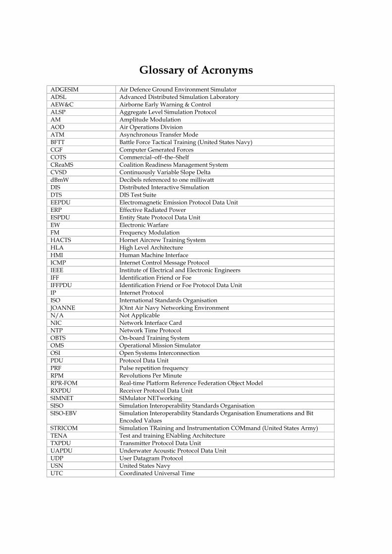
Glossary of Acronyms ADGESIM Air Defence Ground Environment Simulator ADSL Advanced Distributed Simulation Laboratory AEW&C Airborne Early Warning & Control ALSP Aggregate Level Simulation Protocol AM Amplitude Modulation AOD Air Operations Division ATM Asynchronous Transfer Mode BFTT Battle Force Tactical Training (United States Navy) CGF Computer Generated Forces COTS Commercial–off–the–Shelf CReaMS Coalition Readiness Management System CVSD Continuously Variable Slope Delta dBmW Decibels referenced to one milliwatt DIS Distributed Interactive Simulation DTS DIS Test Suite EEPDU Electromagnetic Emission Protocol Data Unit ERP Effective Radiated Power ESPDU Entity State Protocol Data Unit EW Electronic Warfare FM Frequency Modulation HACTS Hornet Aircrew Training System HLA High Level Architecture HMI Human Machine Interface ICMP Internet Control Message Protocol IEEE Institute of Electrical and Electronic Engineers IFF Identification Friend or Foe IFFPDU Identification Friend or Foe Protocol Data Unit IP Internet Protocol ISO International Standards Organisation JOANNE JOint Air Navy Networking Environment N/A Not Applicable NIC Network Interface Card NTP Network Time Protocol OBTS On-board Training System OMS Operational Mission Simulator OSI Open Systems Interconnection PDU Protocol Data Unit PRF Pulse repetition frequency RPM Revolutions Per Minute RPR-FOM Real-time Platform Reference Federation Object Model RXPDU Receiver Protocol Data Unit SIMNET SIMulator NETworking SISO Simulation Interoperability Standards Organisation SISO-EBV Simulation Interoperability Standards Organisation Enumerations and Bit
Encoded Values STRICOM Simulation TRaining and Instrumentation COMmand (United States Army) TENA Test and training ENabling Architecture TXPDU Transmitter Protocol Data Unit UAPDU Underwater Acoustic Protocol Data Unit UDP User Datagram Protocol USN United States Navy UTC Coordinated Universal Time

DSTO-TR-1768
1
1. Introduction
Acceptance testing is a necessary stage in any complex procurement, as it determines whether the supplier has satisfied the requirements of the contract [1]. Over the next ten years the Department of Defence will acquire many new platform training simulators that will support distributed team training, otherwise known as network-enabled training simulators. For distributed team training to be reliable and cost effective, and therefore embraced by the user, simulators must be network interoperable. Interoperability is ensured by thoroughly testing simulators against the relevant distributed simulation standards. However, at present there is no uniform acceptance testing procedure. A majority of the new platform training simulators will support the Distributed Interactive Simulation (DIS) standard. These include the AP-3C Advanced Flight Simulator, Airborne Early Warning & Control (AEW&C) Operational Mission Simulator (OMS), C-130H and C-130J flight simulators, Armed Reconnaissance Helicopter (ARH) simulator, Super Seasprite simulator, and FFG Upgrade Project Onboard Training System (OBTS) and team trainer. Several simulators supporting High Level Architecture (HLA) will be delivered in the future, including the F/A-18 Hornet Aircrew Training System (HACTS). Whilst all existing network-enabled training simulators, including the RAAF AP-3C OMS, Air Defence Ground Environment Simulator (ADGESIM), and RAN FFG and ANZAC operations room team trainers, have supported the DIS standard, the requirements specification and acceptance testing procedures have varied. As a result some simulators have a lesser technical ability to participate in distributed training exercises than others, due both to requirements oversight, varying model resolution, and defects present in the delivered product. To reduce this risk for new simulators, AOD has published several reports to advise projects, at the requirements specification stage, on the minimum requirements for interoperability and issues relating to network interoperability [2-4]. The intention of this report is to inform project staff and engineers, involved in the development and execution of acceptance testing, on the need for extensive testing. This is accomplished through dissemination of distributed simulation concepts, and specification of a recommended acceptance testing procedure and test cases for the DIS standard. The test cases could be adapted to the other distributed simulation standards, such as HLA, if the need were to arise. The procedure presented in this report is based on prior testing work performed by task NAV 01/196, “JOint Air Navy Network Environment (JOANNE)”, and will serve as a template for future testing work under task NAV 04/026, “Air Maritime Team Training”. Ideally, it will address the current lack of a uniform acceptance testing procedure for network-enabled training simulators.

DSTO-TR-1768
2
2. Distributed Team Training Definitions
This section defines distributed simulation and interoperability concepts relevant to platform training simulators. These definitions are also applicable to real-time constructive simulations; however testing of such simulations is not the focus of this report. 2.1 Platform Training Simulator
The term ‘platform training simulator’ is employed by AOD to describe a human-in-the loop training simulator that models the virtual battlespace at the tactical level in real-time. Platforms, otherwise known as combat units, and tracked weapons are referred to as entities within the simulation. Whilst there are no set rules for simulator design, a generic platform training simulator normally consists of five components, that are physical dispersed throughout the training facility:
• Trainer. The component manned by the trainee (or trainees), for example operator consoles, cockpit, operations room, or bridge. The platform that the trainer represents is referred to as the ownship1, and is referred to as the “ownship entity” within the simulation.
• Control station. The component used to configure the simulator and control the execution of a training exercise. Standard functions include defining the reference point (or game centre), starting and stopping the exercise, and manually repositioning the ownship.
• Instructor/Asset station(s). The component that manages additional entities within the exercise, such as those representing the red force. Traditionally these stations have been manned by instructors and the additional entities manually driven. However, there is a move to reduce manning requirements through the use of intelligent agent technology. The instructor station may also incorporate functionality of the control station or debrief components.
• Debrief. The component that provides performance feedback to the trainee (or trainees) following the execution of an exercise.
• Simulation Computer. The component that performs platform, sensor and emitter modelling, and display rendering calculations.
The traditional approach to simulator design has been to interconnect the various components using a proprietary communications protocol, with an additional distributed simulation interface component provided to network the simulator to other training simulators. A recent approach has been to use distributed simulation for internal simulator communications [5]. This can reduce the engineering effort required to both build and maintain the simulator, as there is a large market of commercial off-the-shelf distributed simulation products, and an increasing number of experienced engineers. An example of each approach is shown in Figure 1.
1 Variations include, ownairship, ownhelo and owntank. For consistency, ownship is used throughout this report.

DSTO-TR-1768
3
Figure 1: System block diagram of the RAN FFG Integrated Team Training Facility on the left (reproduced from [6]), and RAAF ADGESIM on the right 2.2 Distributed Simulation
In the context of platform training simulators, distributed simulation is the provision of a shared virtual battlespace, in which entities can interact. Information representing the virtual battlespace is known as “ground truth” and is exchanged over a data communications network. This information is perceived independently by each simulator. The way in which a simulator internally models the virtual battlespace is called the internal model. The internal model is often different for each training simulator, for example one simulator may consider the earth’s surface to be a flat two-dimensional space, whilst another may model it as an ellipsoid. The internal model is a direct result of the simulator’s functional requirements and resulting engineering design decisions. To conduct distributed training, a standard model is required across all simulators on the network. Rather than forcing all simulators to behave in the same manner, a secondary model, known as the network model, is used. Models, be they internal or network, are composed of objects and/or interactions2. An object describes information that is persistent for some duration of the simulation, for example, the visual signature of a weapon. An interaction describes an instantaneous event, for example, the detonation of a weapon. Objects and interactions are parameterised by field values.
2 Whilst recent distributed simulation standards boast additional modelling features, such as object inheritance, object composition and method invocation, information is effectively described through interactions and objects.

DSTO-TR-1768
4
It is important to realise that the network model is purely a conceptual representation of the virtual battlespace, and does not define how objects and interactions are exchanged between simulators. The exchange process is instead defined by the network protocol, also known as the messaging or wire protocol. The network protocol often leverages existing network transport technologies, such as Internet Protocol (IP) or Asynchronous Transfer Mode (ATM). Established distributed simulation standards, including SIMulator NETworking (SIMNET), Distributed Interactive Simulation (DIS) and the Aggregate Level Simulation Protocol (ALSP)
3 define a baseline network model and protocol. More recent standards, including HLA and the Test and training ENabling Architecture (TENA), leave the definition of the network model and protocol open as an engineering design decision. These design decisions, if not appreciated, can lead to non-interoperability, and are discussed further in section 2.4. Simulation model terminology varies between each distributed simulation standard, and is listed for comparison in Table 1, along with the terminology adopted by this report.
Table 1: Distributed simulation model terminology
Adopted Term DIS TENA ALSP and HLA Interaction Protocol Data Unit Message Interaction
Object Protocol Data Unit with heartbeat
Stateful Distributed Object Object
Field Field Attribute Attribute (objects) Parameter (interactions)
2.3 Distributed Simulation Interface
The distributed simulation interface component of a network enabled training simulator performs two tasks. The first is translation, where information represented by the internal model is translated into a network model representation, and vice-versa. Information is often discarded or augmented during the translation process; coordinate conversion, for example, is almost always required. The second task is exchange, where information represented by the network model is marshalled4 and sent to other hosts, and conversely received and un-marshalled. The conceptual layers of a generic distributed simulation interface are shown in Table 2 for DIS, TENA, HLA and the International Standards Organisation Open Systems Interconnection (ISO/OSI) network model [7]. Objects and interactions generated by the simulator flow down through the layers, whereas objects and interactions generated by remote simulators flow up through the layers. The former is referred to as sending, and the latter as receiving. When the distributed simulation interface is not in use, the simulator is said to be operating in stand-alone mode.
3 The primary user of ALSP, the US Army sponsored Joint Training Confederation, maintains a network model standard. 4 Marshalling, also known as serialisation, is the process of encoding data into an architecture- independent format such that it is suitable for transmission over a network.

DSTO-TR-1768
5
Table 2: The conceptual layers and tasks of a distributed simulation interface.
Layer DIS TENA HLA ISO/OSI
Internal Model Internal model Internal model
Defined by ‘Simulation
Object Model’ 7- Application
↕ Translation ↕
Network Model PDU types
Defined by ‘Local Range
Object Model’
Defined by ‘Federation
Object Model’ 7- Application
↕ Exchange ↕
6- Presentation Network Protocol
Byte ordering, Data structures,
Heartbeats, Timeouts
Defined by ‘TENA
Middleware’
Defined by ‘Run Time
Infrastructure’ 5- Session
4- Transport
3- Network
2- Data Link Network
Transport UDP/IP Typically IP Typically IP
1– Physical
2.4 Interoperability
Interoperability is defined as the ability of two or more systems or components to exchange information, and to make appropriate use of that information [8]. During the development of DIS and HLA, simulator interoperability was decomposed into three distinct levels: compliant, interoperable and compatible [9, 10]. 1. Compliant. A simulator is considered to be compliant if the distributed simulation interface
is implemented in accordance with the relevant standards. This is achieved at the acceptance testing stage, by ensuring that the translation and exchange tasks are performed correctly. Compliance can be further decomposed into structural and syntactic compliance (relating to the network protocol), and semantic compliance (relating to the network model).
2. Interoperable. Two or more simulators are considered to be interoperable if they can participate in a distributed training exercise. This is achieved at the requirements specification stage, by ensuring that each simulator is built to equivalent network model and network protocol standards. Design decisions relating to the choice of network model and protocol should be reviewed thoroughly, as these directly influence this level of interoperability.
3. Compatible. Two or more simulators are considered to be compatible if they can participate in a distributed training exercise and achieve training objectives. This is achieved at the training needs analysis stage by ensuring that the capabilities and performance of each simulator are sufficient to meet training objectives. The challenge for Defence is to ensure that adequate training needs analyses are performed in relation to distributed team training. The expression “fair fight” is frequently used to describe compatibility.

DSTO-TR-1768
6
These definitions demonstrate that a compliant simulator will not necessarily be interoperable with other compliant simulators, and likewise, that just because two or more simulators are interoperable, they are not necessarily compatible for distributed team training. The three levels are applicable to other distributed simulation standards. 2.5 Acceptance Testing
The objective of acceptance testing is to establish that the supplier has satisfied the requirements of the contract, therefore mitigating the risk of defects or other inadequacies throughout the project’s operational lifetime. It occurs prior to ownership of the project deliverable being handed over to the Commonwealth, and is conducted in the intended operational environment (the training facility), as opposed to the supplier’s development environment. Ideally, few defects should be identified at the time of acceptance, as modern software engineering practices encourage testing to be conducted throughout the product development cycle [11]. Unfortunately such practices are not always adopted, or if adopted, are later discarded in the rush to meet delivery schedules. Thorough testing of a simulator’s distributed simulation interface is required for three reasons. Firstly, distributed simulation protocols are often intolerant to implementation faults; one incorrectly set field (or data bit) may be sufficient to prevent distributed team training, or lessen its effectiveness. Secondly, distributed simulation standards are often ambiguous and incomplete to some degree, meaning that two standards compliant simulators may be non-interoperable due to the suppliers forming different interpretations of the standard’s intent. Finally, the defects are seldom apparent until the distributed simulation interface is used in anger. The cost of resolving defects at short notice for a training exercise is often prohibitive. Ideally, acceptance testing of the distributed simulation interface should be performed in pursuit of interoperability with other training simulators, not compliance with the supplier’s interpretation of the standard. Procurement contracts should enable the Commonwealth to invoke an independent third party during acceptance testing of the distributed simulation interface. Such a third party would be tasked to review acceptance test plans and/or carry out independent testing on behalf of the Commonwealth.
3. Acceptance Testing Procedure
Whilst there is much literature available on the subject of software and systems testing, a majority of it is written from the perspective of the supplier, not the customer. The time and resources allocated to acceptance testing are often limited; therefore the procedure needs to be efficient, repeatable and authoritative. The remainder of this section details the recommended acceptance testing procedure, which consists of three stages: planning, the test activity, and documentation. 3.1 Planning
Planning identifies the aspects of the simulator to be tested, the level of manning required to operate the trainer and/or instructor stations, and the anticipated duration of testing. Often a

DSTO-TR-1768
7
simple approach is taken, where testing of all functionality related to the distributed simulation interface is proposed. As in the planning for a distributed training exercise, agreement must be reached on data, including platform types and the location within the virtual battlespace whereby testing will take place. Deployment and set-up of the test equipment, including data classification and network media compatibility, must also be considered. Given that the distributed simulation interface shares connectivity with other components of the simulator, it is desirable to perform distributed simulation tests following preliminary acceptance of the stand-alone simulator. Otherwise, the results of testing may be influenced by defects present in the stand-alone simulator. 3.2 Test Activity
The test activity occurs at the training facility and often spans several days, depending on the amount of testing proposed in the planning stage. The black box testing methodology, which evaluates the functionality or performance of the system irrespective of internal implementation details, is employed. Figure 2 shows the black box view of a simulator, where the exposed interfaces are the Human Machine Interface (HMI) and Network Interface Card (NIC). The functional requirements are examined, by stimulating the black box with input actions and witnessing the resulting output.
Figure 2: Black box view of a generic training simulator; the components are not shown to any scale
The test case is a fundamental concept in testing, which identifies the expected output from a specific input. A test case is considered to pass if the output witnessed during the test execution matches the expected output, or is within the permitted tolerance range. The development of test cases is described in section 4. Test cases are classified by the interface from which the expected output is generated:
• Configuration testing verifies that the simulator can be configured appropriately for a distributed training exercise. Existing distributed simulation standards do not define minimum requirements for simulator configuration.
• Send testing verifies that network data sent by the simulator complies with the relevant simulation standards. The input actions for send tests normally relate to the HMI.

DSTO-TR-1768
8
• Receive testing verifies that the simulator responds correctly to network data generated by remote simulators. The input actions for receive tests normally relate to the NIC.
It is desirable to perform testing in the order listed above as this ensures that a passive analysis of the simulator’s capabilities is performed prior to stimulating it with network data. This is informally known as the “crawl-walk-run” approach. Certain test cases, such as dead reckoning accuracy tests, require detailed analysis of the witnessed output, and are best performed following the test activity (for example, in a laboratory environment) to make more efficient use of time with the simulator. To facilitate this, relevant HMI actions and network data sent and received by the NIC are recorded in a test log, which is a combination of written notes and data files, where log entries are time stamped to enable correlation of events. 3.3 Documentation
Following a test activity, a document shall be produced that details the results of testing. The report can be styled as either: a formal report that introduces the simulator and describes the outcomes of the test activity, or a compilation of individual incident reports, where each cites the outcome of a specific test case, and is typically no more than a page. Regardless of the style used, the result of each test case should be highlighted by severity, as shown below. Where a test case has failed, the potential impact on distributed training exercises should be explored, and the input action and witnessed output noted, to aid the supplier in resolving the fault. Ultimately the report should indicate whether the simulator is compliant, and if it is not compliant, make recommendations for change. If significant faults are identified, the testing activity should be repeated to ensure that the supplier makes appropriate corrections.
• FAULT. Has potential to prevent interoperability with another simulator. Resolution is advised.
• ISSUE. Does not comply with the standard, or lacks some functionality. However this is unlikely to prevent interoperability with another simulator. Resolution is desirable.
• ACTION. The test data was insufficient to draw a firm conclusion. Further investigation is advised.
4. Test Case Development
Test cases serve to demonstrate the implementation of individual distributed simulation requirements. There are several types of requirements for distributed simulation, as shown in Table 3. As an example, a network model requirement may stipulate “simulation of Identification Friend or Foe (IFF) transponder Mode 3/A”. Each requirement type differs in terms of complexity, test case development methodology and the equipment suitable to facilitate test execution.

DSTO-TR-1768
9
Network transport and hardware requirements are normally tested using a small number of test cases, for example, to demonstrate Internet Control Message Protocol (ICMP) ping replies, network address and port configuration, and hardware compatibility with other network devices, such as switches, hubs and routers. For each network protocol requirement, test cases are developed to demonstrate exchange of data, for example, packet heartbeat intervals, byte ordering and data structure placement. Because the network protocol is often dependant on the network model, these tests are carried out in parallel with network model tests. However, for some distributed simulation standards, it is possible to independently test the network protocol implementation [12]. For each network model requirement, the related objects and interactions are identified, and test cases written for relevant permutations of the field values, with respect to send and receive testing. For example, the IFF requirement stated above would be evaluated with at least four test cases, in order to demonstrate sending and receiving of Mode 3/a when the transponder is enabled and disabled. If the requirement stipulates configurable data, such as platform and system enumerations, additional test cases are written to demonstrate re-configuration of the data.
Table 3: Distributed simulation requirements
Requirement Testing approach Suitable test equipment
Network hardware Verify that hardware is installed and functioning Another network device
Network transport Examine transport protocol implementation Transport protocol manipulation utilities
Network protocol
Network model → Entities → Tactical communications
Examine network model and network protocol implementation
Object and interaction generation and field instrumentation equipment Entity generation and battlespace visualisation tools Simulated radio transceivers
Training
→ Pre-recorded
Playback pre-recorded scenario work-up log files from other training simulators
Log file playback software
→ Manned Conduct distributed training exercise
Scenario generator or another training simulator
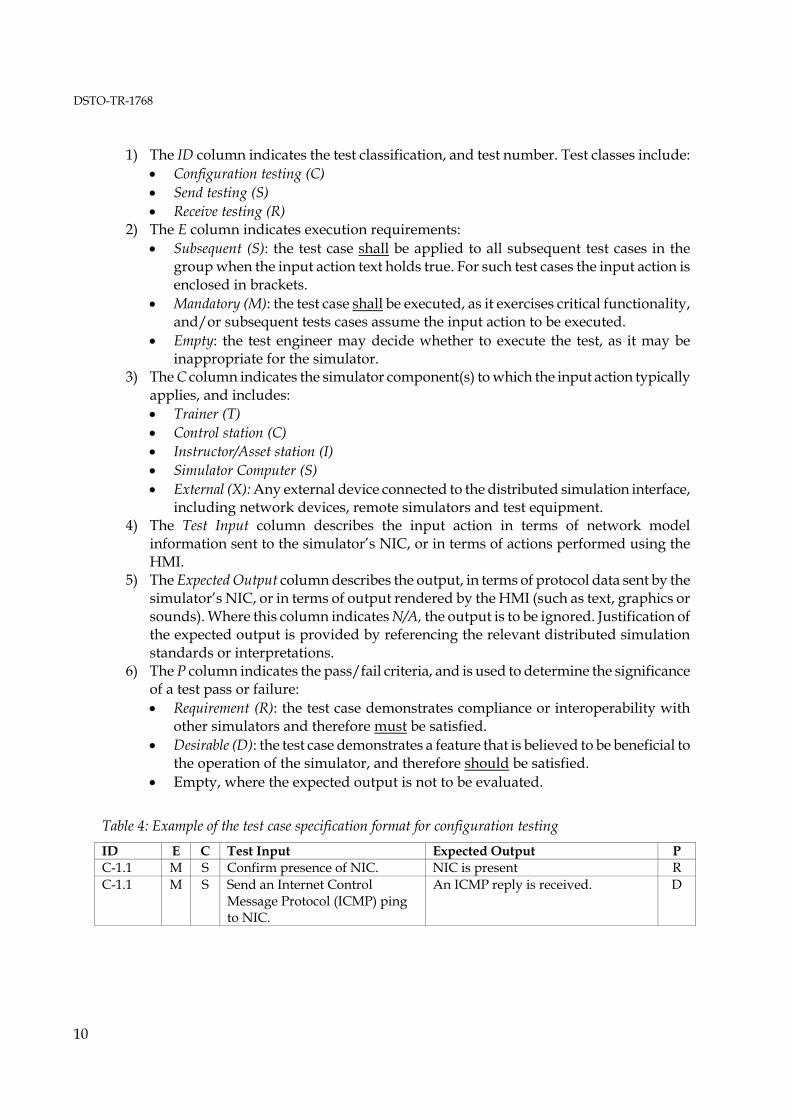
Training requirements are evaluated by demonstrating use of the simulator under anticipated operational conditions, for example, the execution of a standard training scenario or loading of the system with a prescribed number of entities. Test cases may also address relevant operator manuals and maintenance training packages, although this has been outside the scope of testing previously undertaken by the authors. A standard test case specification format was developed, based on existing test documentation standards [13], and is detailed in the remainder of this section. Related tests cases are grouped into tables. The columns are described below, with an example for configuration, send and receive testing shown in Tables 4, 5 and 6 respectively.
DSTO-TR-1768
10
1) The ID column indicates the test classification, and test number. Test classes include:
• Configuration testing (C) • Send testing (S) • Receive testing (R)
2) The E column indicates execution requirements: • Subsequent (S): the test case shall be applied to all subsequent test cases in the
group when the input action text holds true. For such test cases the input action is enclosed in brackets.
• Mandatory (M): the test case shall be executed, as it exercises critical functionality, and/or subsequent tests cases assume the input action to be executed.
• Empty: the test engineer may decide whether to execute the test, as it may be inappropriate for the simulator.
3) The C column indicates the simulator component(s) to which the input action typically applies, and includes: • Trainer (T) • Control station (C) • Instructor/Asset station (I) • Simulator Computer (S) • External (X): Any external device connected to the distributed simulation interface,
including network devices, remote simulators and test equipment. 4) The Test Input column describes the input action in terms of network model
information sent to the simulator’s NIC, or in terms of actions performed using the HMI.
5) The Expected Output column describes the output, in terms of protocol data sent by the simulator’s NIC, or in terms of output rendered by the HMI (such as text, graphics or sounds). Where this column indicates N/A, the output is to be ignored. Justification of the expected output is provided by referencing the relevant distributed simulation standards or interpretations.
6) The P column indicates the pass/fail criteria, and is used to determine the significance of a test pass or failure: • Requirement (R): the test case demonstrates compliance or interoperability with
other simulators and therefore must be satisfied. • Desirable (D): the test case demonstrates a feature that is believed to be beneficial to
the operation of the simulator, and therefore should be satisfied. • Empty, where the expected output is not to be evaluated.
Table 4: Example of the test case specification format for configuration testing
ID E C Test Input Expected Output P C-1.1 M S Confirm presence of NIC. NIC is present R C-1.1 M S Send an Internet Control
Message Protocol (ICMP) ping to NIC.
An ICMP reply is received. D

DSTO-TR-1768
11
Table 5: Example of the test case specification format for send testing
ID E C Test Input (HMI) Expected Output (NIC) P S-1.0 S C (any IFF object) System Active is set to ‘True’ R S-1.1 M T Activate IFF Mode Charlie. IFF object is updated:
i. Mode Charlie is set to ‘On’ R
Table 6: Example of the test case specification format for receive testing
ID E C Test Input (NIC) Expected Output (HMI) P R-1.0 M X Create a test entity within IFF
interrogation range of ownship. N/A -
R-1.1 M X Activate the IFF transponder i. Set System Active to ‘True’
ii. Set Mode Charlie to ‘On’
Mode Charlie is rendered. R
For brevity, network model fields are highlighted in italics, bitfields are underlined, and enumerated value names are wrapped in single quotes. Test cases may request the test engineer to take note of information witnessed, such as available configuration options, for recording into the test log.
5. Distributed Interactive Simulation Acceptance Testing
The DIS application protocol is defined by the Institute of Electrical and Electronic Engineers (IEEE) standards 1278.1-1995 and 1278.1A-1998 [14, 15], and supported by the Simulation Interoperability Standards Organization (SISO), which maintains an enumerations and bit encoded values document (the SISO-EBV) [16]. The capabilities of DIS, and potential benefits for training, have been reported previously by AOD [17-19]. The DIS network model describes ground truth information for real-time platform simulations. An equivalent model is employed by the HLA Real-time Platform Reference Federation Object Model (RPR-FOM). Each simulator is responsible for sending objects that describe the position, appearance and emissions originating from entities under its control. Simulators may also send interactions when collisions are detected, or weapons are fired or detonated. Simulators receive these objects and interactions and use them to stimulate sensor systems (such as infrared, Electronic Warfare (EW), sonar or radio) and visualisation systems (such as an out of the window display) within the trainer. The DIS network protocol employs formatted messages, called Protocol Data Units (PDUs), to describe platform kinematics, electromagnetic and acoustic emitters, radio communications and so on. PDUs are sent to other simulators over a local or wide area network. Whilst DIS supports reliable and best effort Internet Protocol (IP) transports, normally broadcast User Datagram Protocol (UDP) is used. Interactions are exchanged by sending individual PDUs, whereas objects are exchanged by sending PDUs at a regular interval (referred to as the

DSTO-TR-1768
12
heartbeat interval), or when the field values have exceeded a pre-determined threshold. The lifecycle of an object is depicted in Figure 3.
Figure 3: Object lifecycle from the perspective of the sending simulator
The minimum DIS requirements to achieve distributed team training in the Air and Maritime domain, namely the PDU types, have been identified by studying existing simulator implementations and those presently under development [3]. The test cases presented in Appendices A, B and C attempt to test all functionality offered by these PDU types. Therefore, not all of the test cases will be appropriate for all simulators, for example, not all simulators model underwater acoustic emitters. The latest revision of the DIS application protocols standard was published in 1998. Under IEEE policy, the standard must be reaffirmed, revised or withdrawn every five years. Whilst it was reaffirmed in December 2002, the many ambiguities which still exist within the standard are a contributing factor to interoperability problems. A SISO study group, initiated by industry and US Department of Defense users, was formed in 2003, to document problems within the current standard and draft appropriate clarifications [20]. It has since transformed into a Product Development Group (PDG), with a charter to develop a revised IEEE 1278.1-200X standard [21]. Since the publication of a revised DIS standard is unlikely to occur before FY2005/06, the remainder of this section details the standard interpretations adopted by the JOANNE initiative. These interpretations have been contributed to the SISO DIS PDG, and AOD will push for their inclusion in a revised IEEE standard. 5.1 Common Problems
Each entity within a simulation exercise is identified by an Entity ID, consisting of Site, Host and Number fields, which is often written as site:host:number. All objects and interactions are associated with an Entity ID. The site field indicates the training establishment, host indicates the simulator, and number indicates a specific entity generated by the simulator. As there is no governing body or central computer to allocate Entity IDs, it is necessary to ensure that simulators are not configured with conflicting Site and Host numbers. To prevent this from occurring, the JOANNE initiative has allocated site numbers for existing ADF training facilities, relevant platforms, and research establishments [19]. The Entity State PDU (ESPDU) describes the fundamental characteristics of an entity, including position, velocity and type, where type is a seven digit enumeration (hereafter referred to as the entity enumeration) that identifies the specific platform or weapon system,

DSTO-TR-1768
13
for example, ‘HMAS SYDNEY’ or ‘RIM-7H SEA SPARROW’. Additional objects are used to describe emission characteristics in greater detail. Where the information described by the objects or interactions is insufficient to stimulate a simulator’s sensor suite, it is necessary for the simulator to maintain a local database of supplemental information. For example, DIS does not model the above-surface sound generated by a platform, therefore simulators that reproduce such sounds must maintain a local database of sounds. The entity enumeration is often used as a database lookup key, although some PDU types also provide a field for indicating the database lookup key. To conduct a training exercise, the database for each simulator must be populated with information pertaining to the platforms present in the exercise. The number of entities a simulator can generate, and the number of remote entities it can render, vary for each simulator. Whilst this is primarily a compatibility issue, rather than one of compliance or interoperability, it is recommended that testing be conducted for at least 250 entities. This figure is based on the 2003 Coalition Readiness Management System (CReaMS) exercise, where approximately 100 entities were generated by two training facilities and one live asset (US destroyer). Future CReaMS scenarios are expected to involve additional live assets (RAN and US ships) and larger entity counts. 5.2 Protocol Data Unit Header
All PDUs include a common header structure that identifies the DIS version, PDU type, exercise number and timestamp. The standard does not require simulators to support multiple versions of DIS. For example, a simulator may send and receive version 6 PDUs, but discard version 5 PDUs. Problems arising from version interoperability can be overcome using version translation equipment, however, it is recommended that simulators send DIS version 6, and receive both versions 5 and 6. PDU type numbers 129 through 255 are reserved for experimental modelling, and have been used by some simulators to exchange objects or interactions that are not defined in the standard. Whilst this is acceptable under the standard, it is important to ensure that the same experimental PDU type number is not used for different purposes. Appendix D lists known experimental PDU types. The timestamp field indicates the minutes past the current hour. Simulators can be configured to operate in absolute or relative time, where absolute time indicates that the simulation clock is synchronised to Coordinated Universal Time (UTC), and relative time, that it is not. Absolute and relative time simulators can co-exist in the same exercise. It is recommended that simulators support both absolute and relative time, and provide a means to synchronise the clock to a Network Time Protocol (NTP) server. The DIS protocol standard requires PDUs to be individually encapsulated in network transport data units (for example, each PDU is encapsulated in a UDP packet). Some DIS implementations provide an optional ‘bundling’ feature to improve network utilisation

DSTO-TR-1768
14
efficiency, whereby multiple PDUs are encapsulated in each network transport data unit. It is necessary to ensure that this feature is documented, as bundled and non-bundled simulators are often non-interoperable. Note that although this feature is discussed in IEEE 1278.2, the requirements are not described adequately [22]. 5.3 Entity State (Object)
The Entity State PDU describes the position, type, force orientation, appearance, and marking text (or call sign) of an entity. Some simulators do not render the entity if the entity enumeration is not present within the simulator’s database. It is recommended that when an unknown entity type is received, the closest equivalent database entry be used. The standard defines eleven dead reckoning algorithms. It is recommended that simulators only send the first five algorithms, as those remaining are not widely supported. If an unsupported algorithm is received, it should be regarded as the ‘Static’ dead reckoning algorithm. The SISO-EBV document defines three marking text character sets. It is recommended that only the ‘ASCII’ character set be sent, and that if an unknown character set is received, the marking text field be regarded as vacant. The marking text field may be used for representing callsigns or tail numbers. The network model does not convey entity bounding dimensions, and therefore this information must be stored in a local database. 5.4 Collision
The Collision PDU describes the collision interaction between an entity and another entity, or between an entity and a terrain object. There are no known ambiguities within the standard, other than the need to store bounding dimension information (identified in section 5.3). 5.5 Fire and Detonation
The Fire and Detonation PDUs describe the fire and detonation of a tracked or untracked weapon. When tracked weapons are in transit, objects are sent to represent the weapon entity (namely Entity State and emissions). The network model does not convey the amount of damage resulting from the detonation of a weapon, and therefore this information must be stored in a local database. 5.6 Electromagnetic Emissions (Object)
The Electromagnetic Emission PDU (EEPDU) describes the emission characteristics of radar and countermeasure equipment. It is used to stimulate electronic warfare support systems.

DSTO-TR-1768
15
The EEPDU employs a hierarchical structure that describes zero or more emission systems, where each system describes zero or more beams. Each beam describes radio frequency emission parameters and (optionally) indicates the Entity IDs that the beam is tracking or jamming. As beams and systems are activated and deactivated, appropriate structures are added and removed. The sender assigns each system and beam a unique number such that they can be identified on receipt, regardless of structure placement. An example of beam deactivation is shown in Figure 4.
Figure 4: Two Electromagnetic Emission PDU structures are shown demonstrating the deactivation of Beam A within System A
Some simulators model radar systems that involve frequent activation and deactivation of beams. Rather than repeatedly adding and removing a beam structure from the PDU, some simulators set the beam Effective Radiated Power field to zero, to indicate deactivation (and non-zero to indicate activation). This convention is considered an acceptable use of the standard. The standard does not define how the receiver should behave if a remote simulator stops sending EEPDUs. There are two possible interpretations:
1) Do not perform timeout processing, and continue to associate the most recently received update with the entity;
2) Perform timeout processing, whereupon at timeout, discard all emission information associated with the entity.
The second interpretation is recommended, using a timeout interval of 12 seconds (or 5 seconds multiplied by 2.4; the default EEPDU heartbeat interval multiplied by the IEEE heartbeat multiplier). The standard does not define how the sender should behave when emissions or acoustics are to be no longer sent for an entity, for example when an entity’s radar has been destroyed. There are three possible responses:
1) Continue to send updates with a zero number of emission systems whilst the associated entity exists within the simulation;
2) Send one (or more) final update with a zero number of emission/acoustic systems, and assume receiving simulators will perform timeout processing;
3) No longer send updates, and assume receiving simulators will perform timeout processing.

DSTO-TR-1768
16
Both the first and second responses are suitable, however the second is recommended as it reduces unnecessary network bandwidth utilisation. The third response should be avoided, as simulators that do not perform timeout processing will continue to associate the most recently received update with the entity. The standard does not define valid ranges for the Beam Azimuth Sweep and Beam Elevation Sweep fields. A half angle range of [0, π) is assumed. The standard does not define valid ranges for the Beam Sweep Sync field. A range of [0,100) is assumed. The standard does not define how to populate the Jamming Mode Sequence field. It is recommended that this field be set to zero, and be ignored on receipt. The EEPDU does not convey side lobes, scan patterns and beam patterns. Each simulator must store this information in a local database, and use the System Name and/or Beam Parameter Index fields to look up appropriate database entries. 5.7 Identification, Friend or Foe (Object)
The Identification Friend or Foe PDU (IFFPDU) describes the state of IFF transponder and interrogator equipment. It comprises either one or two information layers, where the first conveys mode and code information, and the optional second layer describes electromagnetic emission characteristics. The standard does not define how the receiver should behave if a remote simulator stops sending IFFPDUs. It is recommended that timeout processing be performed, using a timeout interval of 24 seconds (or 10 seconds multiplied by 2.4; the default IFFPDU heartbeat interval multiplied by the IEEE heartbeat multiplier). The standard does not define valid ranges for the Beam Azimuth Sweep and Beam Elevation Sweep fields, which are present in Layer 2. A half angle range of [0, π) is assumed. The standard does not define valid ranges for the Beam Sweep Sync field. A range of [0,100) is assumed. 5.8 Underwater Acoustic (Object)
The Underwater Acoustic PDU (UAPDU) describes shaft rotations and underwater emissions generated by sub-surface or surface platforms, or low flying aircraft. It is structured similarly to the EEPDU, in that it defines zero or more emissions systems, where each system describes zero or more beams. As beams and systems are activated and deactivated, appropriate structures are added and removed. The sender assigns each system and beam a unique number such that they can be identified on receipt, regardless of structure placement within the PDU. Like the EEPDU, the standard does not define how the sender should behave when underwater acoustic emissions are no longer required, for example, when an entity’s active

DSTO-TR-1768
17
sonar has been destroyed. The same interpretations described for the EEPDU can be applied to the UAPDU. The standard defines a three minute UAPDU heartbeat interval. This results in a slow exercise start-up time, as a simulator joining a DIS exercise may have to wait three minutes before receiving the first UAPDU update. A decreased heartbeat interval, between 10 seconds and three minutes, is considered acceptable. The standard does define how the receiver should behave if a remote simulator stops sending UAPDUs. It is recommended that a timeout processing be performed, using a timeout interval of 432 seconds (or 180 seconds multiplied by 2.4; the default UAPDU heartbeat interval multiplied by the IEEE heartbeat multiplier). The UAPDU does not convey source power or beam patterns. Each simulator must store this information in a database, and use the Acoustic Name or/or Emission Parameter Index field to look-up on appropriate database entry. 5.9 Radio Communications Family
The PDU types described in the follow section relate to simulated radio communications, defined by the standard as the Radio Communication family. 5.9.1 Transmitter (Object)
The Transmitter PDU describes the operational state of radio communications transmitter (or transceiver) equipment, including frequency, power, modulation and transmit state. The Antenna Location field indicates the location of the transmitter antenna, using a three dimensional vector with the origin at the centre of the earth. A non-standard, but widely adopted convention, is to set this field to all zeros (x=y=z=0) to instruct receivers not to apply radio frequency propagation effects to the signal. This convention is typically used by simulated radios that are not tightly coupled with the simulator, and are therefore unaware of the ownship’s location (and hence the ownship’s antenna location). However, not all receiver implementations support this convention, and accordingly will consider the signal to be out of range. It is recommended that ADF simulators support this convention. The Frequency and Bandwidth fields describe the transmitter’s centre frequency and half-power bandwidth (bandwidth between -3 dB points). Some poorly implemented simulators require the receiver to be tuned to the exact centre frequency of the transmitter. It is recommended that simulators do not implement an exact frequency match, as rounding errors, introduced during internal floating point to integer number conversions, may prevent this from occurring. The modulation parameter fields (Spread Spectrum, Major Modulation, Detail Modulation and System) describe the type of signal modulation being transmitted (for example, AM and FM), and enable receiving simulators to apply appropriate propagation effects to the transmitted signal. Most simulators require the receiver to be tuned to the same modulation parameter

DSTO-TR-1768
18
configuration as the transmitter, as this mimics real world behaviour. It is therefore necessary to ensure that all simulators support at least one common modulation parameter configuration. It is recommended that simulators support reception of at least the modulation parameter configurations listed in Table 7.
Table 7: List of recommended modulation parameters
Description Spread Spectrum Major Modulation
Detail Modulation System
AM All zeros 1 (‘Amplitude’) 2 (‘AM’) 1 (‘Generic’) FM All zeros 3 (‘Angle) 1 (‘FM’) 1 (‘Generic’) BFTT5 All zeros 2 2 1 (‘Generic’) The Crypto System and Crypto Key ID fields describe the encryption algorithm and a pseudo encryption key. The standard does not define the usage of these fields for transmitters that can be switched between plain and secure communication modes, and can therefore be interpreted one of two ways:
1) Set the Crypto System to zero to indicate plain, and non-zero to indicate secure. 2) Set the lower 15-bits of Crypto Key ID to zero to indicate plain, and non-zero to indicate
secure. To ensure interoperability with both interpretations, it is recommended that transmitters set either Crypto System or the lower 15-bits of Crypto Key ID fields to zero to indicate plain, and both to non-zero to indicate secure. It is recommended that receivers consider transmissions to be plain if either field is set to zero, or secure if otherwise. The 16th bit of the Crypto Key ID describes the use of ‘base band encryption’ or ‘diphase encryption.’ The authors are unaware of any simulator implementation using this bit, and recommend it being sent as ‘band base’, and the value ignored on receipt. 5.9.2 Signal (Object)
The Signal PDU describes a stream of digitised data associated with a transmission. Whilst many data types, including voice and tactical data links, are supported, only voice is discussed below. A standard for tactical data link representation within the Signal PDU is currently under development, however this only addresses Link-16 simulation, not Link-11 [23]. Since there is a limit to the amount of digitised audio that can be stored in each Signal PDU, it is necessary to send multiple PDUs to convey an audio transmission. The standard requires simulators to support ‘8-bit mu-law’ encoding at 8000 Hz, however it does not recommend the number of audio samples to be sent within each Signal PDU. The number of samples has an effect on the bit rate utilization and audio latency, as shown in Table 8. An examination of
5 The United States Navy (USN) Battle Force Tactical Training (BFTT) program uses a non-standard modulation parameter configuration.

DSTO-TR-1768
19
several simulators has shown that sample values between 320 and 1024 are frequently used, and accordingly a value within this range is recommended.
Table 8: Effective audio latency and bandwidth utilisation for different number of samples (using ‘8-bit mu-law’ encoding at 8000 Hz)
Number of Samples per Signal PDU
Effective Audio Latency6
Effective UDP/IP Bandwidth Utilization
240 30 ms 80.00 kbps 320 40 ms 76.00 kbps 384 48 ms 74.00 kbps 480 60 ms 72.00 kbps 512 64 ms 71.50 kbps 824 103 ms 68.66 kbps 1024 128 ms 67.75 kbps 1440 180 ms 66.66 kbps
The ‘8-bit mu-law’ encoding system provides a 2:1 audio compression ratio, resulting in 64 kbps per channel (excluding PDU and UDP/IP overheads). Better compression ratios are available by using more computationally expensive algorithms, however the standard does not require these to be implemented. It is desirable for simulators to also support Continuously Variable Slope Delta (CVSD) encoding, as this offers a 8:1 data compression ratio, resulting in 16 kbps per channel (excluding overheads). 5.9.3 Receiver (Object)
The Receiver PDU describes the operational state of radio receiver equipment, including tuned frequency and modulation. There are no known ambiguities within the standard. 5.10 Simulation Management Family
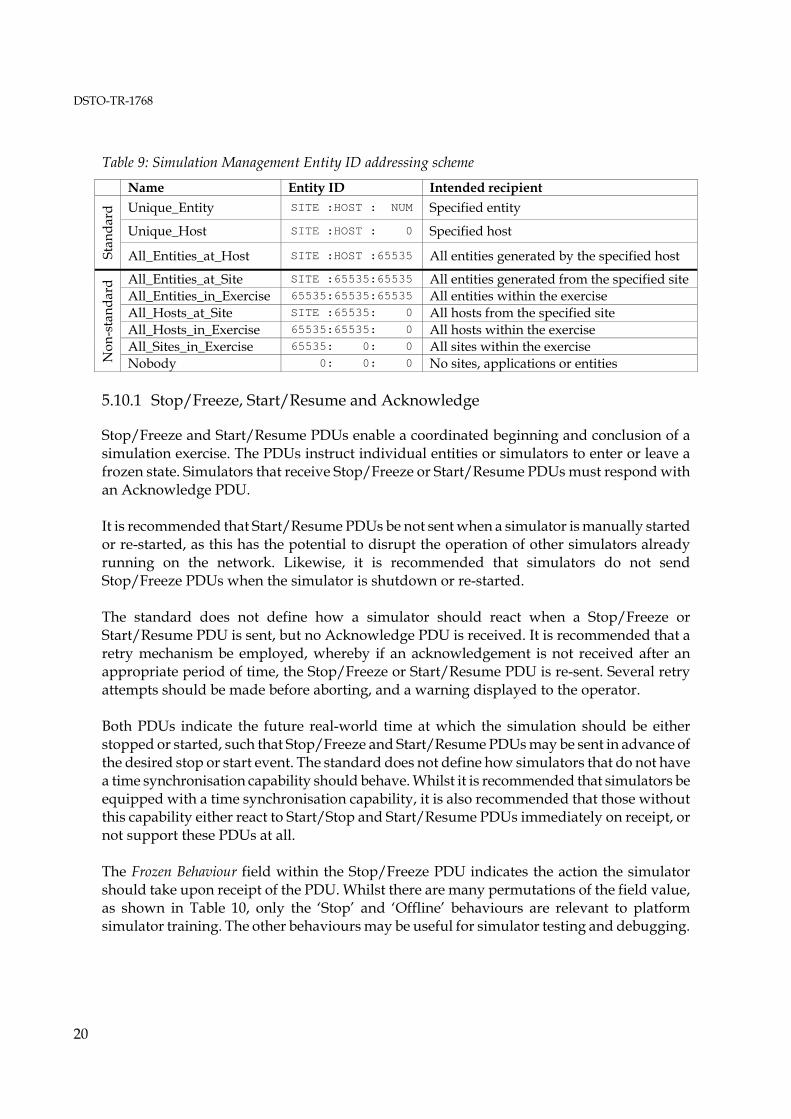
The simulation management family of PDUs enables simulators to be controlled remotely or to exchange information that is not supported by existing PDU types. All simulation management PDUs include a Receiving Simulator ID field, enabling the PDUs to be directed to a specific entity. Special Entity ID values are reserved to indicate all, or no, entities generated by a specific simulator. A Simulation Management guidance document was drafted to accompany the IEEE 1278.1A standard, but was never formally published [24]. This document detailed an Entity ID addressing scheme that expands the existing special Entity ID values, as shown in Table 9. This addressing scheme has been employed by several ADF simulators, and it is recommended that new simulators support the addressing scheme.
6 The effective audio latency value is equivalent to the duration of audio stored within each Signal PDU. Actual audio latency may be greater, due to network and processing latencies.
DSTO-TR-1768
20
Table 9: Simulation Management Entity ID addressing scheme
Name Entity ID Intended recipient Unique_Entity SITE :HOST : NUM Specified entity
Unique_Host SITE :HOST : 0 Specified host
Stan
dard
All_Entities_at_Host SITE :HOST :65535 All entities generated by the specified host
All_Entities_at_Site SITE :65535:65535 All entities generated from the specified site All_Entities_in_Exercise 65535:65535:65535 All entities within the exercise All_Hosts_at_Site SITE :65535: 0 All hosts from the specified site All_Hosts_in_Exercise 65535:65535: 0 All hosts within the exercise All_Sites_in_Exercise 65535: 0: 0 All sites within the exercise
Non
-sta
ndar
d
Nobody 0: 0: 0 No sites, applications or entities 5.10.1 Stop/Freeze, Start/Resume and Acknowledge
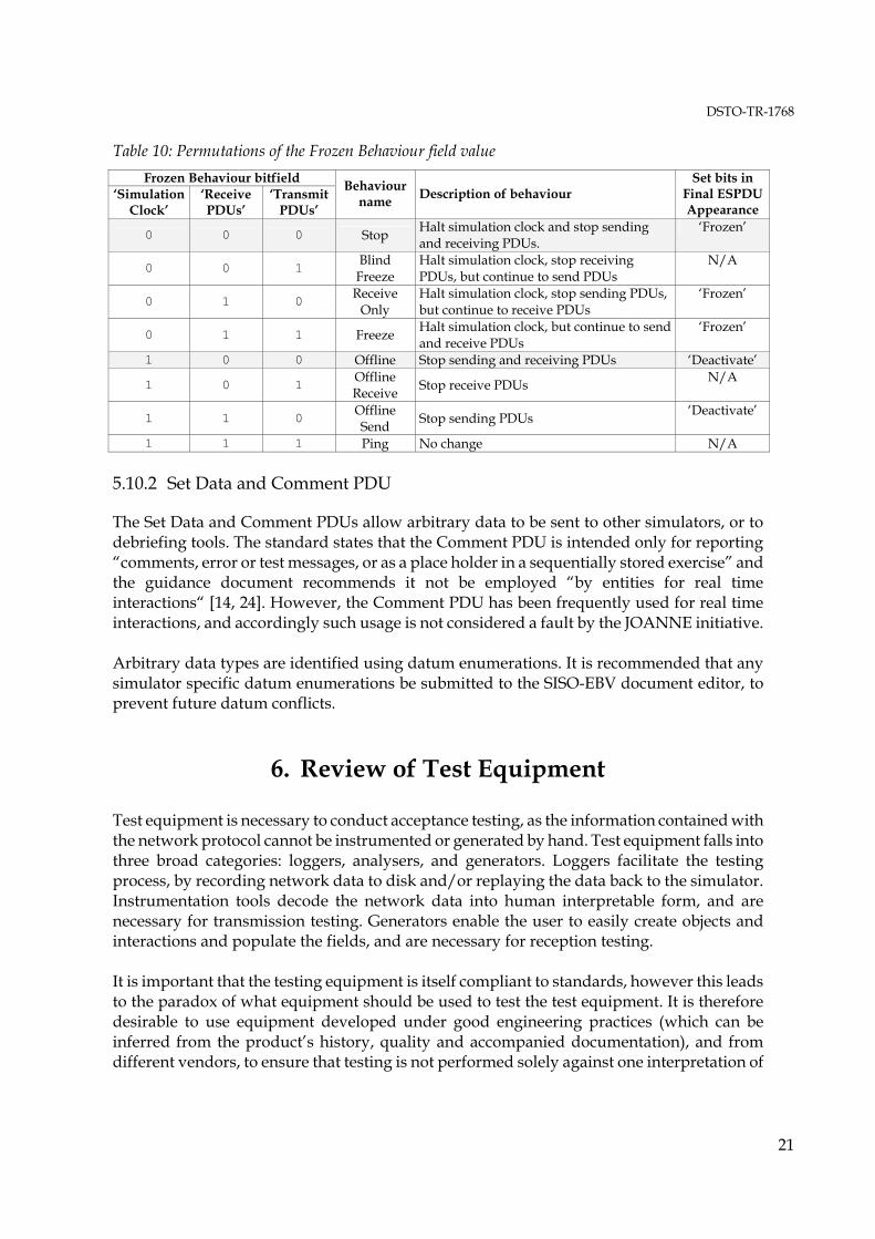
Stop/Freeze and Start/Resume PDUs enable a coordinated beginning and conclusion of a simulation exercise. The PDUs instruct individual entities or simulators to enter or leave a frozen state. Simulators that receive Stop/Freeze or Start/Resume PDUs must respond with an Acknowledge PDU. It is recommended that Start/Resume PDUs be not sent when a simulator is manually started or re-started, as this has the potential to disrupt the operation of other simulators already running on the network. Likewise, it is recommended that simulators do not send Stop/Freeze PDUs when the simulator is shutdown or re-started. The standard does not define how a simulator should react when a Stop/Freeze or Start/Resume PDU is sent, but no Acknowledge PDU is received. It is recommended that a retry mechanism be employed, whereby if an acknowledgement is not received after an appropriate period of time, the Stop/Freeze or Start/Resume PDU is re-sent. Several retry attempts should be made before aborting, and a warning displayed to the operator. Both PDUs indicate the future real-world time at which the simulation should be either stopped or started, such that Stop/Freeze and Start/Resume PDUs may be sent in advance of the desired stop or start event. The standard does not define how simulators that do not have a time synchronisation capability should behave. Whilst it is recommended that simulators be equipped with a time synchronisation capability, it is also recommended that those without this capability either react to Start/Stop and Start/Resume PDUs immediately on receipt, or not support these PDUs at all. The Frozen Behaviour field within the Stop/Freeze PDU indicates the action the simulator should take upon receipt of the PDU. Whilst there are many permutations of the field value, as shown in Table 10, only the ‘Stop’ and ‘Offline’ behaviours are relevant to platform simulator training. The other behaviours may be useful for simulator testing and debugging.
DSTO-TR-1768
21
Table 10: Permutations of the Frozen Behaviour field value Frozen Behaviour bitfield
‘Simulation Clock’
‘Receive PDUs’
‘Transmit PDUs’
Behaviour name Description of behaviour
Set bits in Final ESPDU Appearance
0 0 0 Stop Halt simulation clock and stop sending and receiving PDUs.
‘Frozen’
0 0 1 Blind Freeze
Halt simulation clock, stop receiving PDUs, but continue to send PDUs
N/A
0 1 0 Receive Only
Halt simulation clock, stop sending PDUs, but continue to receive PDUs
‘Frozen’
0 1 1 Freeze Halt simulation clock, but continue to send and receive PDUs
‘Frozen’
1 0 0 Offline Stop sending and receiving PDUs ‘Deactivate’
1 0 1 Offline Receive Stop receive PDUs N/A
1 1 0 Offline Send Stop sending PDUs ‘Deactivate’
1 1 1 Ping No change N/A 5.10.2 Set Data and Comment PDU
The Set Data and Comment PDUs allow arbitrary data to be sent to other simulators, or to debriefing tools. The standard states that the Comment PDU is intended only for reporting “comments, error or test messages, or as a place holder in a sequentially stored exercise” and the guidance document recommends it not be employed “by entities for real time interactions“ [14, 24]. However, the Comment PDU has been frequently used for real time interactions, and accordingly such usage is not considered a fault by the JOANNE initiative. Arbitrary data types are identified using datum enumerations. It is recommended that any simulator specific datum enumerations be submitted to the SISO-EBV document editor, to prevent future datum conflicts.
6. Review of Test Equipment
Test equipment is necessary to conduct acceptance testing, as the information contained with the network protocol cannot be instrumented or generated by hand. Test equipment falls into three broad categories: loggers, analysers, and generators. Loggers facilitate the testing process, by recording network data to disk and/or replaying the data back to the simulator. Instrumentation tools decode the network data into human interpretable form, and are necessary for transmission testing. Generators enable the user to easily create objects and interactions and populate the fields, and are necessary for reception testing. It is important that the testing equipment is itself compliant to standards, however this leads to the paradox of what equipment should be used to test the test equipment. It is therefore desirable to use equipment developed under good engineering practices (which can be inferred from the product’s history, quality and accompanied documentation), and from different vendors, to ensure that testing is not performed solely against one interpretation of
DSTO-TR-1768
22
the distributed simulation standards. The tools currently employed by the JOANNE initiative for testing are listed below, along with a brief description each. 6.1 Tcpdump
Tcpdump7 is an open-source command-line based utility that intercepts data layer network packets and displays a summary for each packet to the screen, or records network packets to disk. The recording capabilities of Tcpdump are preferred over standard DIS loggers, because all network data, including UDP/IP headers, is captured, and the log file format is documented. 6.2 DIS Test Suite
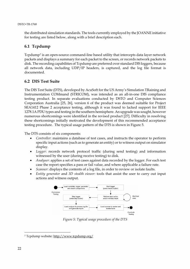
The DIS Test Suite (DTS), developed by AcuSoft for the US Army’s Simulation TRaining and Instrumentation COMmand (STRICOM), was intended as an all-in-one DIS compliance testing product. In separate evaluations conducted by DSTO and Computer Sciences Corporation Australia [25, 26], version 6 of the product was deemed suitable for Project SEA1412 Phase 2 acceptance testing, although it was found to lacked support for IEEE 1278.1A PDU types and testing in the southern hemisphere. An upgrade was sought, however numerous shortcomings were identified in the revised product [27]. Difficulty in resolving these shortcomings initially motivated the development of this recommended acceptance testing procedure. The typical usage pattern of the DTS is shown in Figure 5. The DTS consists of six components:
• Controller: maintains a database of test cases, and instructs the operator to perform specific input actions (such as to generate an entity) or to witness output on simulator display.
• Logger: records network protocol traffic (during send testing) and information witnessed by the user (during receive testing) to disk.
• Analyser: applies a set of test cases against data recorded by the logger. For each test case the report specifies a pass or fail value, and where applicable a failure rate.
• Scanner: displays the contents of a log file, in order to review or isolate faults. • Entity generator and 3D stealth viewer: tools that assist the user to carry out input
actions and witness output.
Figure 5: Typical usage procedure of the DTS
7 Tcpdump website: http://www.tcpdump.org/

DSTO-TR-1768
23
6.3 PDU Generator and Maritime Entity Generator
The DIS PDU Generator and Maritime Entity Generator were developed by DSTO to assist Project SEA1412 Phase 2 acceptance testing [28, 29], and have since been used in other test activities. The PDU Generator presents a screen containing buttons for common PDU types, where pressing a button will result in a PDU being sent. The Maritime Entity Generator simulates a single surface platform, and provides controls for navigating the platform; firing weapons; and activating communications, IFF, radar and sonar equipment. Both tools populate the bulk of PDU fields with fixed values, for example, the IFFPDU System Type field is always set to ‘Mark X/XII/ATCRBS/Mode S Interrogator’. Therefore, whilst these tools are well suited for preliminary testing, they are inadequate when attempting to isolate the cause of faults to a particular field value. 6.4 Netdump
MÄK Technologies8 Netdump decodes IEEE 1278.1 and 1278.1A PDUs as they are received, displaying individual fields to the screen. The primary use of Netdump is to determine the value of a field. Basic filtering can be applied externally using Unix text filtering tools, such as ‘grep’. Netdump is not a stand-alone product, and is included with the MÄK VR-Link Toolkit. 6.5 DisCommMonitor
EMDee Technology9 produces DIS and HLA radio communications toolkits for Microsoft Windows. The company offers a free tool that passively monitors the state of simulated radio equipment by displaying Transmitter and Signal PDU fields on the screen. 6.6 Stealth Viewer
Whilst not specifically intended for testing, 2D and 3D visualisations of the virtual battle space, and are used to subjectively evaluate the suitability of dead reckoning implementations.
8 MÄK Technologies website: http://www.mak.com/ 9 EMDee Technology website: http://www.emdee.com/

DSTO-TR-1768
24
7. Summary and Conclusion
This report has described distributed simulation concepts in relation to distributed team training, and a procedure for acceptance testing network-enabled training simulators. The report has detailed DIS test equipment and standard interpretations adopted by the JOANNE initiative, for commonly used PDU types identified in prior research. These interpretations have been contributed to the SISO DIS Product Development Group for potential inclusion into a revised IEEE standard. Test cases for these PDU types, forming the bulk of this report, are presented in the Appendices. The procedures presented in this report will facilitate future analysis of training simulators testing conducted under the NAV 04/026 “Air Maritime Team Training” task, in particular the FFG Upgrade Project OBTS, AP-3C AFS and Super Seasprite simulator. If the need arises to test simulators supporting the HLA standard (for example the future F/A-18 HACTS), the existing DIS test cases could be adapted with minimal effort to test the RPR-FOM.
8. References
1 Defence Material Organisation, (2004), "Defence Procurement Policy Manual - Version 5.0".
2 Zalcman, L.B., (2004), "What Questions Should I Ask Regarding DIS or HLA Interoperability For My ADF Simulator Acquisition?" Proceedings of the 9th Simulation, Training and Technology Conference, Canberra, Australia.
3 Zalcman, L.B., (2004), "What Distributed Interactive Simulation (DIS) Protocol Data Units (PDUs) Should My Australian Defence Force Simulator Have?" DSTO Technical Report, DSTO-TR-1565.
4 Zalcman, L.B., "What DIS PDU Fields Need To Be Populated In My ADF DIS Simulator?" DSTO Technical Report (in draft).
5 Guckenberger, D., Guckenberger, E., Whitney, R., and G. Hall, (1996), "The Third Wave - DIS++/HLA: Next Generation of Standards for Internal Architecture of Simulators". 15th DIS Workshop.
6 McGarity, M., (2004), "TADIL Simulation and Network Centric Warfare". Proceedings of the 9th Simulation Technology and Training Conference, May 2004.
7 ISO/IEC 7498-1:1994(E), (1994), "Information technology - Open Systems Interconnection - Basic Reference Model: The Basic Model".
8 IEEE 610-1990, (1990), "IEEE Standard Computer Dictionary: A Compilation of IEEE Standard Computer Glossaries". ISBN 1-55937-079-3.
9 Ratzenberger, A., (1995), "DIS Compliant, Interoperable and Compatible: The Need for Definitions and Standards". Proceedings of the 12th DIS Workshop on Standards for the Interoperability of Distributed Simulations, Orlando, Florida.
DSTO-TR-1768
25
10 Loper, M.L., (1996), "HLA Testing: Separating Compliance from Interoperability". Proceedings 14th DIS Workshop on Standards for the Interoperability of Distributed Simulations, Orlando, Florida.
11 Hetzel, Bill, (1988), "The Complete Guide to Software Testing (Second Edition)". ISBN 0-89435-242-3.
12 Symington, S., Kaplan, J., Kuhl, F., Tufarolo, J., Weatherly, R. and J. Nielsen, (2000), "Verifying HLA RTIs". Fall Simulation Interoperability Workshop, September 2000, Orlando, Florida.
13 IEEE 829-1998, (1998), "IEEE Standard for Software Test Documentation".
14 IEEE 1278.1-1995, (1995), "IEEE Standard for Information Technology - Protocols for Distributed Interactive Simulation Applications". ISBN 1-55937-572-8.
15 IEEE 1278.1A-1998, (1998), "IEEE Standard for Information Technology - Protocols for Distributed Interactive Simulation Applications". ISBN 0-7381-0174-5.
16 Institute for Simulation and Training, University of Central Florida, (2003), "Enumerations and Bit Encoded Values for Use with Protocols for Distributed Interactive Simulation Applications". Document number IST-CF-03-01.
17 Ryan, P.J. and P.D. Clark, (1997), "Distributed Interactive Simulation for the Royal Australian Navy". DSTO Client Report, DSTO-CR-0075.
18 Clark, P.D., Ryan, P.J. and L.B. Zalcman, (2000), "Advanced Distributed Simulation for the Australian Defence Force". DSTO General Document, DSTO-GD-0255.
19 Zalcman, L.B., Ryan, P.J., Clark, P.D. and M. Britton, (2003), "JOANNE Standards for Training Simulator Interoperability". DSTO Technical Report, DSTO-TR-1462.
20 Terms of Reference (TOR) for the “DIS Study Group” 20 May 2003.
21 Simulation Interoperability Standards Organisation (SISO) Product Nomination for the IEEE 1278.1 Distributed Interactive Simulation (DIS) Product Development Group - September 2004.
22 IEEE 1278.2-1995, (1995), "IEEE Standard for Information Technology - Communication Services and Profiles". ISBN 1-55937-574-4.
23 Draft Link 16 Simulation Standard. Version 2.9, DRAFT (8 September 2004).
24 "Simulation Management Guidance Document - Version 1.1" (October 12, 1995).
25 Ryan, P.J., Clark, P.D. and W. Rose, (2002), "Evaluation of the DIS Test Suite". DSTO Client Report, DSTO-CR-0232.
26 CSC Australia Pty. Ltd., "Evaluation of the DIS Test Suite for Project SEA1412". Document SEA1412/0001/0002.
27 Robbie, A., Ross, P.W. and P.D. Clark, (2003), "Evaluation of the Distributed Interactive Simulation Test Suite Upgrade". DSTO Client Report, DSTO-CR-0298.
28 Ross, P.W. and P.J. Ryan, (2004), "Maritime Entity Generator for Participating in Distributed Interactive Simulation Exercises". DSTO Technical Note, DSTO-TN-0552.

DSTO-TR-1768
26
29 Ryan, P.J., Rose W. and P.W. Ross, (2002), "Protocol Data Unit Generator for Testing Distributed Interactive Simulation Interfaces". DSTO Technical Note, DSTO-TN-0472.
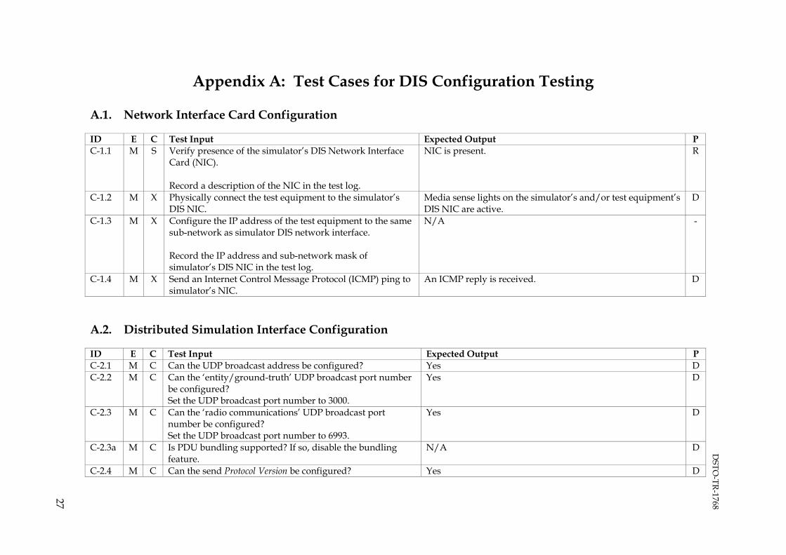
DSTO
-TR-1768
27
Appendix A: Test Cases for DIS Configuration Testing
A.1. Network Interface Card Configuration
ID E C Test Input Expected Output P C-1.1 M S Verify presence of the simulator’s DIS Network Interface
Card (NIC). Record a description of the NIC in the test log.
NIC is present. R
C-1.2 M X Physically connect the test equipment to the simulator’s DIS NIC.
Media sense lights on the simulator’s and/or test equipment’s DIS NIC are active.
D
C-1.3 M X Configure the IP address of the test equipment to the same sub-network as simulator DIS network interface. Record the IP address and sub-network mask of simulator’s DIS NIC in the test log.
N/A -
C-1.4 M X Send an Internet Control Message Protocol (ICMP) ping to simulator’s NIC.
An ICMP reply is received. D
A.2. Distributed Simulation Interface Configuration
ID E C Test Input Expected Output P C-2.1 M C Can the UDP broadcast address be configured? Yes D C-2.2 M C Can the ‘entity/ground-truth’ UDP broadcast port number
be configured? Set the UDP broadcast port number to 3000.
Yes D
C-2.3 M C Can the ‘radio communications’ UDP broadcast port number be configured? Set the UDP broadcast port number to 6993.
Yes D
C-2.3a M C Is PDU bundling supported? If so, disable the bundling feature.
N/A D
C-2.4 M C Can the send Protocol Version be configured? Yes D
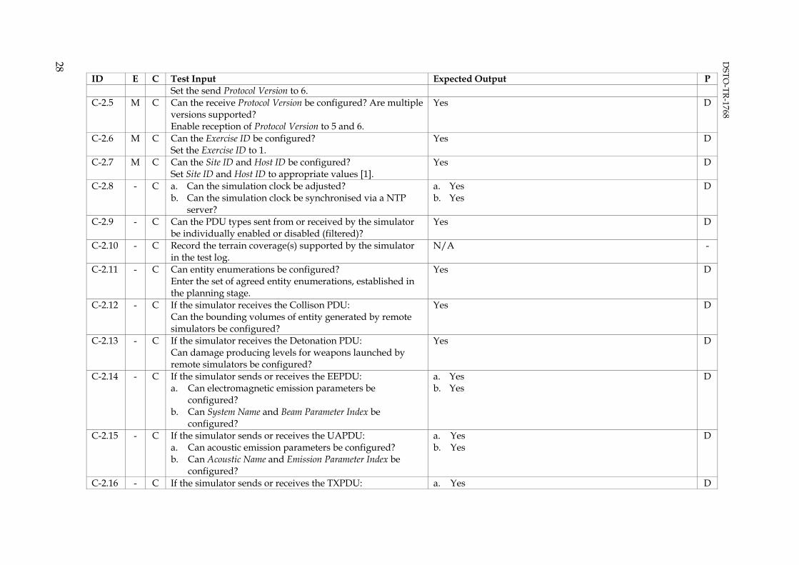
DSTO
-TR-1768
28
ID E C Test Input Expected Output P Set the send Protocol Version to 6.
C-2.5 M C Can the receive Protocol Version be configured? Are multiple versions supported? Enable reception of Protocol Version to 5 and 6.
Yes D
C-2.6 M C Can the Exercise ID be configured? Set the Exercise ID to 1.
Yes D
C-2.7 M C Can the Site ID and Host ID be configured? Set Site ID and Host ID to appropriate values [1].
Yes D
C-2.8 - C a. Can the simulation clock be adjusted? b. Can the simulation clock be synchronised via a NTP
server?
a. Yes b. Yes
D
C-2.9 - C Can the PDU types sent from or received by the simulator be individually enabled or disabled (filtered)?
Yes D
C-2.10 - C Record the terrain coverage(s) supported by the simulator in the test log.
N/A -
C-2.11 - C Can entity enumerations be configured? Enter the set of agreed entity enumerations, established in the planning stage.
Yes D
C-2.12 - C If the simulator receives the Collison PDU: Can the bounding volumes of entity generated by remote simulators be configured?
Yes D
C-2.13 - C If the simulator receives the Detonation PDU: Can damage producing levels for weapons launched by remote simulators be configured?
Yes D
C-2.14 - C If the simulator sends or receives the EEPDU: a. Can electromagnetic emission parameters be
configured? b. Can System Name and Beam Parameter Index be
configured?
a. Yes b. Yes
D
C-2.15 - C If the simulator sends or receives the UAPDU: a. Can acoustic emission parameters be configured? b. Can Acoustic Name and Emission Parameter Index be
configured?
a. Yes b. Yes
D
C-2.16 - C If the simulator sends or receives the TXPDU: a. Yes D
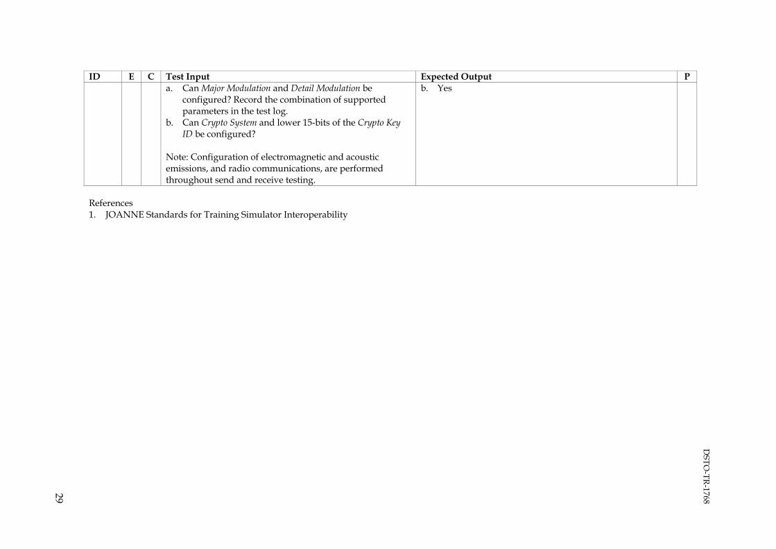
DSTO
-TR-1768
29
ID E C Test Input Expected Output P a. Can Major Modulation and Detail Modulation be
configured? Record the combination of supported parameters in the test log.
b. Can Crypto System and lower 15-bits of the Crypto Key ID be configured?
Note: Configuration of electromagnetic and acoustic emissions, and radio communications, are performed throughout send and receive testing.
b. Yes
References 1. JOANNE Standards for Training Simulator Interoperability

DSTO
-TR-1768
30
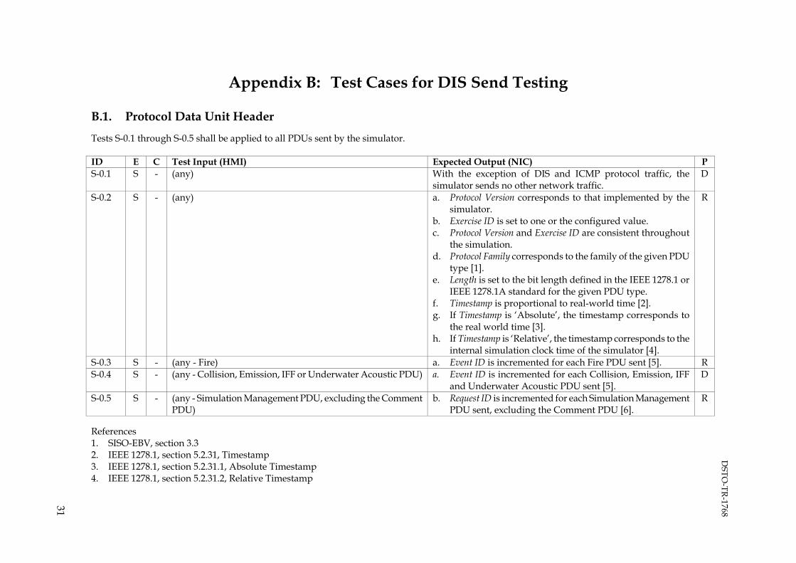
DSTO
-TR-1768
31
Appendix B: Test Cases for DIS Send Testing
B.1. Protocol Data Unit Header
Tests S-0.1 through S-0.5 shall be applied to all PDUs sent by the simulator. ID E C Test Input (HMI) Expected Output (NIC) P S-0.1 S - (any) With the exception of DIS and ICMP protocol traffic, the
simulator sends no other network traffic. D
S-0.2 S - (any) a. Protocol Version corresponds to that implemented by the simulator.
b. Exercise ID is set to one or the configured value. c. Protocol Version and Exercise ID are consistent throughout
the simulation. d. Protocol Family corresponds to the family of the given PDU
type [1]. e. Length is set to the bit length defined in the IEEE 1278.1 or
IEEE 1278.1A standard for the given PDU type. f. Timestamp is proportional to real-world time [2]. g. If Timestamp is ‘Absolute’, the timestamp corresponds to
the real world time [3]. h. If Timestamp is ‘Relative’, the timestamp corresponds to the
internal simulation clock time of the simulator [4].
R
S-0.3 S - (any - Fire) a. Event ID is incremented for each Fire PDU sent [5]. R S-0.4 S - (any - Collision, Emission, IFF or Underwater Acoustic PDU) a. Event ID is incremented for each Collision, Emission, IFF
and Underwater Acoustic PDU sent [5]. D
S-0.5 S - (any - Simulation Management PDU, excluding the Comment PDU)
b. Request ID is incremented for each Simulation Management PDU sent, excluding the Comment PDU [6].
R
References 1. SISO-EBV, section 3.3 2. IEEE 1278.1, section 5.2.31, Timestamp 3. IEEE 1278.1, section 5.2.31.1, Absolute Timestamp 4. IEEE 1278.1, section 5.2.31.2, Relative Timestamp

DSTO
-TR-1768
32
5. IEEE 1278.1, section 5.2.18, Event Identifier record 6. IEEE 1278.1, section 5.2.27, Request ID B.2. Entity State PDU
ID E C Test Input (HMI) Expected Output (NIC) P S-1.0 S - (any – ESPDU) a. ESPDUs are sent at a five second heartbeat interval, or
when an operational parameter changes, or the positional or angular dead reckoning thresholds are exceeded [1].
b. Entity ID is unique for each entity. Neither the Site nor Host field is set to zero or 65535. The Number field is not set to zero, 65534 or 65535 [2, 3].
c. Force ID is set to the appropriate force orientation of the entity, and is defined in SISO-EBV section 4.1 [2].
d. Entity Type corresponds to the platform being simulated, and is defined in SISO-EBV section 4.2 [2, 4].
e. Alternative Entity Type is identical to the Entity Type value, or set to all zeros [2, 4].
f. Location, Orientation and Velocity indicates the location, orientation and velocity of the entity rendered by the simulator [2, 5, 6].
g. The bits set in Appearance and Capabilities are appropriate for the platform being simulated, and are defined in SISO-EBV sections 4.3 and 4.6 respectively [2].
h. Unless the entity has been deactivated the State bit of Appearance is set to ‘Activated’ [1].
i. Dead Reckoning Algorithm is defined in IEEE 1278.1, annex B [2].
j. The dead-reckoned movement of the entity appears smooth and consistent when examined using a third-party 2D/3D visualisation product. Ensure that the entity is not displaced significantly at each state update.
k. Character Set is set to ‘ASCII’ [interpretation]. l. For each articulation parameters record:
i. Parameter Type Designator field is set to 0 to indicate
R
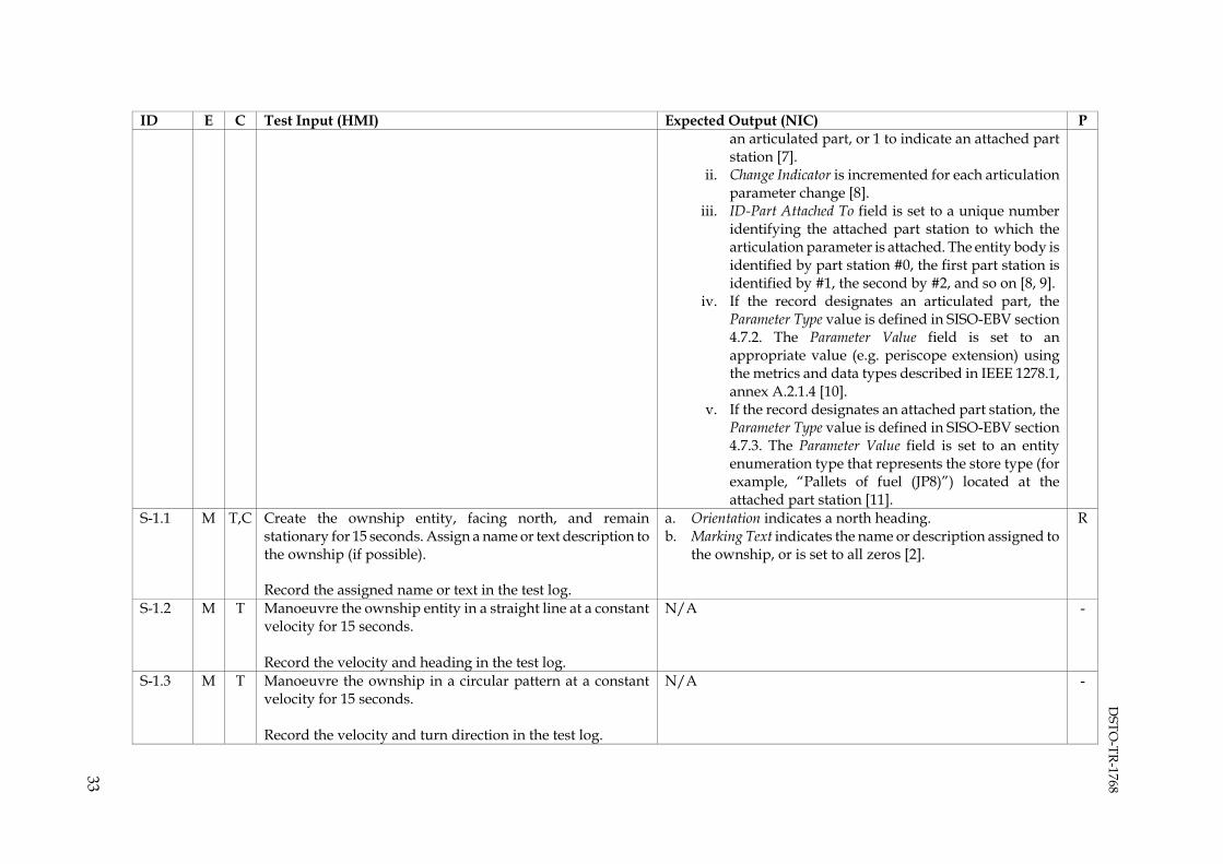
DSTO
-TR-1768
33
ID E C Test Input (HMI) Expected Output (NIC) P an articulated part, or 1 to indicate an attached part station [7].
ii. Change Indicator is incremented for each articulation parameter change [8].
iii. ID-Part Attached To field is set to a unique number identifying the attached part station to which the articulation parameter is attached. The entity body is identified by part station #0, the first part station is identified by #1, the second by #2, and so on [8, 9].
iv. If the record designates an articulated part, the Parameter Type value is defined in SISO-EBV section 4.7.2. The Parameter Value field is set to an appropriate value (e.g. periscope extension) using the metrics and data types described in IEEE 1278.1, annex A.2.1.4 [10].
v. If the record designates an attached part station, the Parameter Type value is defined in SISO-EBV section 4.7.3. The Parameter Value field is set to an entity enumeration type that represents the store type (for example, “Pallets of fuel (JP8)”) located at the attached part station [11].
S-1.1 M T,C Create the ownship entity, facing north, and remain stationary for 15 seconds. Assign a name or text description to the ownship (if possible). Record the assigned name or text in the test log.
a. Orientation indicates a north heading. b. Marking Text indicates the name or description assigned to
the ownship, or is set to all zeros [2].
R
S-1.2 M T Manoeuvre the ownship entity in a straight line at a constant velocity for 15 seconds. Record the velocity and heading in the test log.
N/A -
S-1.3 M T Manoeuvre the ownship in a circular pattern at a constant velocity for 15 seconds. Record the velocity and turn direction in the test log.
N/A -

DSTO
-TR-1768
34
ID E C Test Input (HMI) Expected Output (NIC) P S-1.4 - T,C Modify the ownship’s damage or appearance state (if
possible). For example, landing lights, cockpit lights, open canopy, or specify either a damaged or destroyed state. Record any selected damages or appearance states in the test log.
a. Appropriate bits, defined in SISO-EBV, section 4.3, are set within Appearance to indicate the appearance state.
D
S-1.5 M T,C Delete or deactivate the ownship entity, such that it is no longer present in the simulation.
a. The simulator sends an ESPDU with the State bit of Appearance set to ‘Deactivated’ [1].
b. No further ESPDUs are sent for the ownship entity [1].
R
Repeat - - Repeat test for all four geodetic quadrants on the world. N/A - References 1. IEEE 1278.1, section 4.5.2.1.3, Issuance of the Entity State PDU 2. IEEE 1278.1, section 5.3.3.1, Entity State PDU 3. IEEE 1278.1, section 5.2.14, Entity Identification record 4. IEEE 1278.1, section 5.2.16, Entity Type record 5. IEEE 1278.1, section 5.2.33, Vector record 6. IEEE 1278.1, section 5.2.17, Euler Angles record 7. SISO-EBV, section 4.7.1, Parameter Type Designator 8. IEEE 1278.1, section 5.2.5, Articulation Parameter record 9. IEEE 1278.1, annex A.2.1.1, Numbering of articulated parts 10. IEEE 1278.1, annex A.2.1.3, Parameter Type field 11. IEEE 1278.1, annex A.2.2, Attached parts

DSTO
-TR-1768
35
B.3. Collision PDU
B.3.1 Entity Collision
B.3.2 Terrain Collision
ID E C Test Input (HMI) Expected Output (NIC) P S-2.2.1 M T,C Create the ownship entity. N/A - S-2.2.2 M T Manoeuvre the simulator entity such that it collides with the
terrain, at a velocity greater than 0.1 metres per second (or greater than 0.25 knots). Record the outcome of the collision in the test log.
a. The simulator transmits one Collision PDU [1]. b. Issuing Entity ID corresponds to the ownship entity ID [2]. c. Colliding Entity ID is set to 0:0:0 [2]. d. Collision Type is defined in SISO-EBV section 10.1.1 [2]. e. Mass indicates the mass of the ownship entity (in
kilograms), or is set to zero [2]. f. Velocity indicates to the velocity vector of the ownship
entity, or is set to zero [2, 3]. g. Location wrt Colliding Entity indicates the collision location
rendered by the simulator, or is set to (0, 0, 0) [2, 3].
R
References
ID E C Test Input (HMI) Expected Output (NIC) P S-2.1.1 M T,C Create the ownship entity. N/A - S-2.1.2 M I Create a target entity in the vicinity of the ownship. N/A - S-2.1. M T Manoeuvre the ownship entity such that it collides with the
target entity, at a velocity greater than 0.1 metres per second (or greater than 0.25 knots). Record the outcome of the collision in the test log.
a. The simulator sends one Collision PDU [1]. b. Issuing Entity ID corresponds to the ownship entity ID [2]. c. Colliding Entity ID corresponds to the target entity ID [2]. d. Collision Type is defined in SISO-EBV section 10.1.1 [2]. e. Mass indicates the mass of the ownship entity (in
kilograms), or is set to zero [2]. f. Velocity indicates the velocity vector of the ownship entity,
or is set to all zeros [2, 3]. g. Location wrt Colliding Entity indicates the collision location
rendered by the simulator, or is set to (0, 0, 0) [2, 3].
R

DSTO
-TR-1768
36
1. IEEE 1278.1, section 4.5.2.2.3, Issuance of the Collision PDU 2. IEEE 1278.1, section 5.3.3.2, Collision PDU 3. IEEE 1278.1, section 5.2.33, Vector record B.4. Fire and Detonation PDU
ID E C Test Input (HMI) Expected Output (NIC) P S-3.1 M T,C Create the ownship entity. N/A - S-3.2 M I Create a target entity within fire solution range of the
ownship. N/A -
S-3.3.0 M T Fire a weapon at the target entity. Record the target and weapon type, including description, entity ID and enumeration, in the test log.
a. One Fire PDU is sent [1]. b. Firing Entity ID corresponds to the ownship entity [2]. c. Target Entity ID corresponds to the target entity, or 0:0:0 if no
target is specified [2]. d. If a tracked weapon is fired, Munition ID corresponds to the
weapon entity [2]. e. If an untracked weapon is fired, Munition ID is set to 0:0:0 [2]. f. Fire Mission Index indicates an arbitrary mission number, or is
set to zero [2]. g. Location indicates the weapon firing location rendered by the
simulator [2, 3]. h. Munition Type is defined in SISO-EBV section 4.2.1.2, and
indicates the weapon system fired. For tracked weapons, this must also correspond to the entity enumeration of the weapon entity [4].
i. Warhead is defined in the SISO-EBV section 5.1.1 [4]. j. Fuse is defined in SISO-EBV section 5.1.2 [4]. k. If only one round (or individual projectile) is fired, Quantity
is set to one and Rate is set to zero [4, 5]. l. If multiple rounds (or projectiles) are fired, Quantity is set to
the number of rounds, and Rate is set to the rounds per second firing rate [4, 5].
m. Velocity indicates the launch velocity vector of the weapon [2, 3].
n. Range indicates the range of the fire control solution (in
R
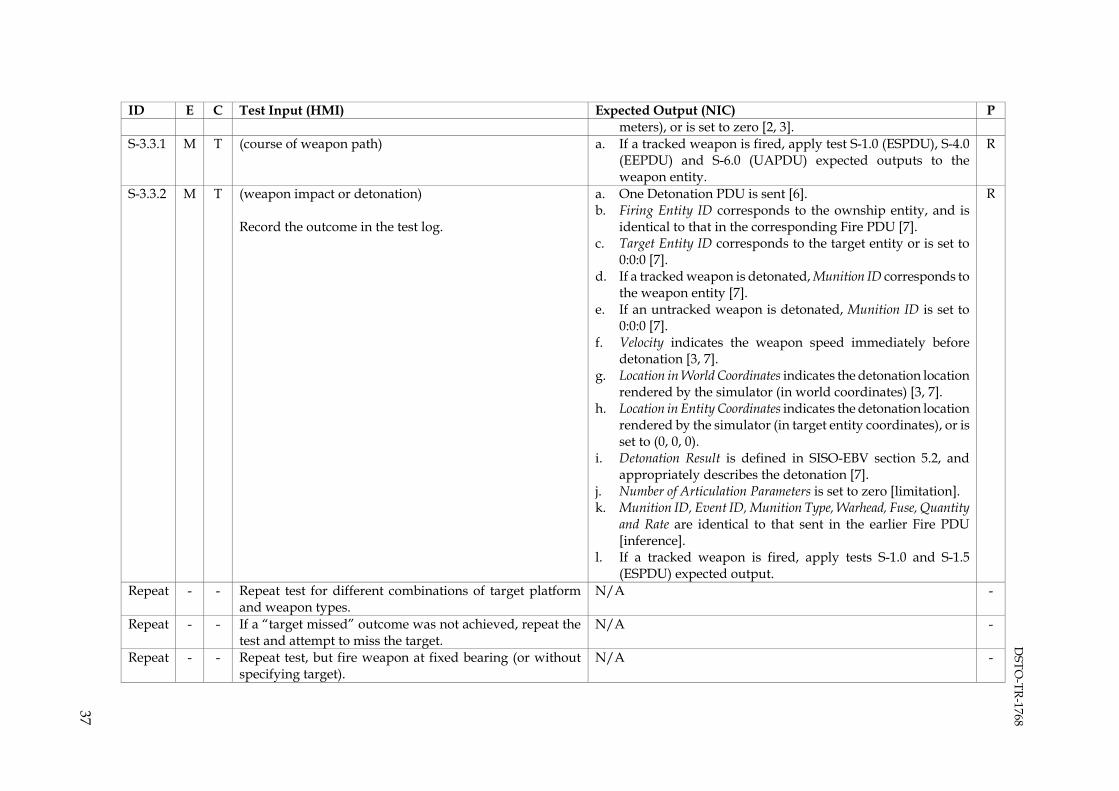
DSTO
-TR-1768
37
ID E C Test Input (HMI) Expected Output (NIC) P meters), or is set to zero [2, 3].
S-3.3.1 M T (course of weapon path) a. If a tracked weapon is fired, apply test S-1.0 (ESPDU), S-4.0 (EEPDU) and S-6.0 (UAPDU) expected outputs to the weapon entity.
R
S-3.3.2 M T (weapon impact or detonation) Record the outcome in the test log.
a. One Detonation PDU is sent [6]. b. Firing Entity ID corresponds to the ownship entity, and is
identical to that in the corresponding Fire PDU [7]. c. Target Entity ID corresponds to the target entity or is set to
0:0:0 [7]. d. If a tracked weapon is detonated, Munition ID corresponds to
the weapon entity [7]. e. If an untracked weapon is detonated, Munition ID is set to
0:0:0 [7]. f. Velocity indicates the weapon speed immediately before
detonation [3, 7]. g. Location in World Coordinates indicates the detonation location
rendered by the simulator (in world coordinates) [3, 7]. h. Location in Entity Coordinates indicates the detonation location
rendered by the simulator (in target entity coordinates), or is set to (0, 0, 0).
i. Detonation Result is defined in SISO-EBV section 5.2, and appropriately describes the detonation [7].
j. Number of Articulation Parameters is set to zero [limitation]. k. Munition ID, Event ID, Munition Type, Warhead, Fuse, Quantity
and Rate are identical to that sent in the earlier Fire PDU [inference].
l. If a tracked weapon is fired, apply tests S-1.0 and S-1.5 (ESPDU) expected output.
R
Repeat - - Repeat test for different combinations of target platform and weapon types.
N/A -
Repeat - - If a “target missed” outcome was not achieved, repeat the test and attempt to miss the target.
N/A -
Repeat - - Repeat test, but fire weapon at fixed bearing (or without specifying target).
N/A -

DSTO
-TR-1768
38
Limitations 1. Articulation parameters, which can be optionally included in the Detonation PDU, are not tested. References 1. IEEE 1278.1, section 4.5.3.2.2, Issuance of the Fire PDU 2. IEEE 1278.1, section 5.3.4.1, Fire PDU 3. IEEE 1278.1, section 5.2.33, Vector record 4. IEEE 1278.1, section 5.2.7, Burst Descriptor record 5. IEEE 1278.1, section 4.5.3.2.3, Single rounds and bursts of fire 6. IEEE 1278.1, section 4.5.3.3.2, Issuance of the Detonation PDU 7. IEEE 1278.1, section 5.3.4.2, Detonation PDU B.5. Electromagnetic Emission PDU
ID E C Test Input (HMI) Expected Output (NIC) P S-4.0 S - (any - EEPDU) a. EEPDUs are sent at a 10 second heartbeat rate, or when an
operational parameter has changed, the elevation or azimuth thresholds (1 degree) are exceeded, or the track/jam entity information has changed [1].
b. Entity ID corresponds to the ownship entity [2]. c. State Update is set to ‘State Update’ or ‘Changed Data
Update’ [2]. d. If State Update is set to ‘State Update’, the EEPDU reports
all emitter systems associated with the entity [3]. e. If State Update is set to ‘Changed Data Update, the EEPDU
reports only those emitter systems that have changed since the last state update [3].
f. For each emitter system: i. System Data Length indicates the bit length of the
emitter system and corresponding beam and track/jam records (in 32-bit words) [2].
ii. System Name is defined in SISO-EBV section 8.1.1, or documented elsewhere [4].
R
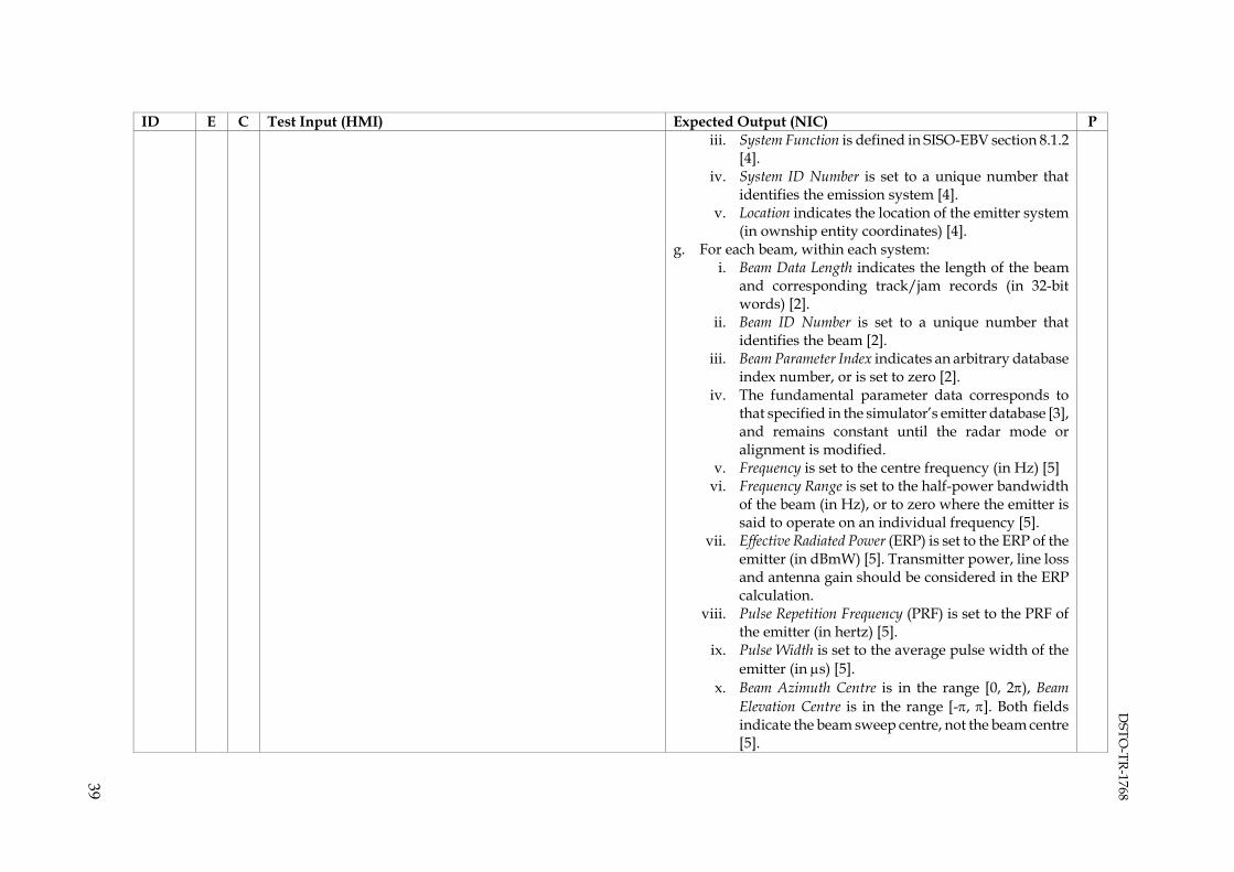
DSTO
-TR-1768
39
ID E C Test Input (HMI) Expected Output (NIC) P iii. System Function is defined in SISO-EBV section 8.1.2
[4]. iv. System ID Number is set to a unique number that
identifies the emission system [4]. v. Location indicates the location of the emitter system
(in ownship entity coordinates) [4]. g. For each beam, within each system:
i. Beam Data Length indicates the length of the beam and corresponding track/jam records (in 32-bit words) [2].
ii. Beam ID Number is set to a unique number that identifies the beam [2].
iii. Beam Parameter Index indicates an arbitrary database index number, or is set to zero [2].
iv. The fundamental parameter data corresponds to that specified in the simulator’s emitter database [3], and remains constant until the radar mode or alignment is modified.
v. Frequency is set to the centre frequency (in Hz) [5] vi. Frequency Range is set to the half-power bandwidth
of the beam (in Hz), or to zero where the emitter is said to operate on an individual frequency [5].
vii. Effective Radiated Power (ERP) is set to the ERP of the emitter (in dBmW) [5]. Transmitter power, line loss and antenna gain should be considered in the ERP calculation.
viii. Pulse Repetition Frequency (PRF) is set to the PRF of the emitter (in hertz) [5].
ix. Pulse Width is set to the average pulse width of the emitter (in μs) [5].
x. Beam Azimuth Centre is in the range [0, 2π), Beam Elevation Centre is in the range [-π, π]. Both fields indicate the beam sweep centre, not the beam centre [5].

DSTO
-TR-1768
40
ID E C Test Input (HMI) Expected Output (NIC) P xi. Beam Azimuth Sweep and Beam Elevation Sweep
indicate the beam sweep volume and are in the range [0, π] [5].
xii. Beam Sweep Sync is in the range [0, 100) [interpretation].
xiii. Beam Function is defined in SISO-EBV section 8.1.4 [2].
xiv. High Density Track/Jam is defined in SISO-EBV section 8.1.5 [2].
xv. If High Density Track/Jam is set to ‘Selected’, Number of Track/Jam Targets is set to zero [2].
xvi. If High Density Track/Jam is set to ‘Not Selected’, Number of Track/Jam Targets indicates the number of targets being tracked or jammed, and is in the range [0, 10] [2].
xvii. Jamming Mode Sequence indicates an arbitrary database value, or is set to zero [2].
h. For each Track/Jam record, within each beam, within each system:
i. Target Entity ID corresponds to a target entity that is being tracked or jammed by the beam [2].
ii. If the target entity is being tracked, System ID Number and Beam ID Number are set to zero [2].
iii. If the target is being jammed, Emitter ID and Beam ID indicate the emitter system and beam that the jammer is attempting to interrupt [2].
S-4.1 M I Create several entities in order to stimulate the ownship radar.
N/A -
S-4.2 M T Create the ownship entity. N/A - S-4.3 M T Activate the radar to a default mode of operation and wait 15
seconds. a. An emitter system that represents the radar system is
present in the EEPDU. R
S-4.4 M T Change each radar alignment parameter (transmission frequency, power, PRF and so on) and wait 15 seconds.
a. For at least one beam in the radar’s emitter system i. The fundamental operation parameters indicate the
new alignment parameters.
R

DSTO
-TR-1768
41
ID E C Test Input (HMI) Expected Output (NIC) P S-4.5 M T Deactivate the primary radar and wait 15 seconds. a. The radar’s emitter system is no longer present in the
EEPDUs [3], or Effective Radiated Power is set to zero for all beams within the radar’s emitter system [interpretation].
R
Repeat - - Repeat for other radar or jamming equipment. N/A - References 1. IEEE 1278.1, section 4.5.6.2.2, Issuance of the Electromagnetic Emission PDU 2. IEEE 1278.1, section 5.3.7.1, Electromagnetic Emission PDU 3. IEEE 1278.1, section 4.5.6.2.1, Information contained in the Electromagnetic Emission PDU 4. IEEE 1278.1, section 5.2.11, Emitter System record 5. IEEE 1278.1, section 5.2.22, Fundamental Parameter Data record B.6. Interrogator Friend or Foe PDU
ID E C Test Input (HMI) Expected Output (NIC) P S-5.0 S - (any – IFFPDU) a. IFFPDUs are sent at a 10 second heartbeat rate, or when
one or more operating parameters have changed and the two second change latency has elapsed [1].
b. System Type, System Name and System Mode are defined in SISO-EBV section 8.3.1.1, and indicate an appropriate IFF transponder device [2].
c. The Change Indicator bit of Change/Options is set to ‘Initial report or change since last report’ or ‘No change since last report’ [1, 3].
d. Antenna Location wrt Entity indicates the location of the transmitter antenna relative to the ownship entity location [4].
e. The Layer 1 bit of Information Layers is set to ‘On’ [5]. f. If one or more modes are enabled, The System On/Off bit of
System Status set to ‘On’ and the Operational Status bit is set to ‘Operational’ [3].
g. If a mode is enabled, the corresponding Parameter N bit of System Status is set to ‘Capable’.
h. The Parameter 6 bit of System Status is set to ‘Not capable’
R

DSTO
-TR-1768
42
ID E C Test Input (HMI) Expected Output (NIC) P [3], and the Status bit of Parameter 6 is set to ‘Off’ [3].
S-5.1 S - (any – IFFPDU – Layer 1) a. The Layer 2 bit of Information Layers is set to ‘Off’ [5]. R S-5.2 S - (any – IFFPDU – Layer 2) a. The Layer 2 bit of Information Layers is set to ‘On’ [5].
b. Layer Number is set to 2 [6]. c. Layer Specific Information is set to zero [7]. d. Length indicates the byte length of the layer 2 header and
beam structures [6]. e. Second Operational Parameter 1 and Second Operational
Parameter 2 are set to zero [8, 9]. f. The beam data and fundamental parameter data
correspond to that specified in the simulator’s emitter database [10].
i. Beam Azimuth Centre is in the range [0, 2π) and Beam Elevation Centre is in the range [-π, π]. Both fields indicate the beam sweep centre, not the beam centre [11].
j. Beam Azimuth Sweep and Beam Elevation Sweep indicate the beam sweep volume and are in the range [0, π) [11].
k. Beam Sweep Sync is in the range [0, 100) [interpretation]. l. If there is more than one emission beam, the beam data
record is set to all zeros [12].
R
S-5.3 M T,C Create the ownship entity. N/A - S-5.4 M T Activate the IFF transponder and wait at least 15 seconds. N/A - S-5.5 M T Squawk Mode 1 code ‘37’ for 15 seconds. a. The Status bit of Parameter 1 is set to ‘On’, the Damage bit is
set to ‘No Damage’ and the Malfunction bit is set to ‘No Malfunction’ [3].
b. The Code Element bits of Parameter 1 indicate ‘37’ [13].
R
S-5.6 M T Squawk Mode 2 code ‘1234’ for 15 seconds. a. The Status bit of Parameter 2 is set to ‘On’, the Damage bit is set to ‘No Damage’ and the Malfunction bit is set to ‘No Malfunction’ [3].
b. The Code Element bits of Parameter 2 indicate ‘1234’ [13].
R
S-5.7 M T Squawk Mode 3/A code ‘2345’ for 15 seconds. a. The Status bit of Parameter 3 is set to ‘On’, the Damage bit is set to ‘No Damage’ and the Malfunction bit is set to ‘No Malfunction’ [3].
b. The Code Element bits of Parameter 3 indicate ‘2345’ [13].
R

DSTO
-TR-1768
43
ID E C Test Input (HMI) Expected Output (NIC) P S-5.8 T Squawk Mode 4 code ‘3456’ for 15 seconds; or
Squawk Mode 4 ‘Valid’, ‘Invalid’ and ‘No response’ each for 15 seconds.
a. The Status bit of Parameter 4 is set to ‘On’, the Damage bit is set to ‘No Damage’ and the Malfunction bit is set to ‘No Malfunction’ [3].
b. If the Alternate Mode 4 bit of Change/Options is set to ‘No’, the Code Element bits of Parameter 4 indicate ‘3456’ [13].
c. If the Alternate Mode 4 bit of Change/Options is set to ‘Yes’, then the Code Element bits of Parameter 4 are set to all ones, and Alternate Parameter 4 is set to either ‘Valid’, ‘Invalid’ or ‘No response’ [3, 15, 16].
D
S-5.9 M T Squawk Mode Charlie for 15 seconds. Record the ownship altitude in the test log.
a. The Status bit of Parameter 5 is set to ‘On’, the Damage bit is set to ‘No Damage’ and the Malfunction bit is set to ‘No Malfunction’ [3].
b. If the Alternate Mode C bit of Change/Options is set to ‘No’, the Negative Altitude and Mode C Altitude bits of Parameter 5 indicate the altitude of the aircraft [3, 16].
c. If the Alternate Mode C bit of Change/Options is set to ‘Yes’, the Negative Altitude bit and Mode C Altitude bits are set to all ones [3, 16].
R
S-5.10 M T Squawk Identification/Flash for 15 seconds. This is also known as Identification of Position (I/P).
a. The Ident/Squawk Flash bit of Modifier is set to ‘On’ [17]. R
S-5.11 M T Squawk Emergency mode for 15 seconds. If there is no emergency option, squawk Mode 3/A code ‘7700’.
a. The Emergency bit of Modifier is set to ‘On’ [17]. b. The Status bit of Parameter 3 is set to ‘On’, the Damage bit is
set to ‘No Damage’ and the Malfunction bit is set to ‘No Malfunction’ [3].
c. The Code Element bits of Parameter 3 indicate ‘7700’.
R
S-5.12 M T Deactivate IFF transponder and wait at least 15 seconds. a. IFFPDUs are no longer sent for the ownship entity, or one or more IFFPDUs are sent with the System On/Off bit of System Status set to ‘Off’ [Interpretation].
R
Repeat - - Repeat entire test where the transponder device is damaged or malfunctioning.
a. The Operational Status bit of System Status may be set to ‘System failed’.
b. The Damage bit of Parameter 1 through Parameter 5 may be set to ‘Damage’.
c. The Malfunction bit of Parameter 1 through Parameter 5 is set to ‘Malfunction’.
D
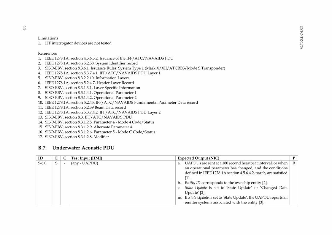
DSTO
-TR-1768
44
Limitations 1. IFF interrogator devices are not tested. References 1. IEEE 1278.1A, section 4.5.6.5.2, Issuance of the IFF/ATC/NAVAIDS PDU 2. IEEE 1278.1A, section 5.2.58, System Identifier record 3. SISO-EBV, section 8.3.6.1, Issuance Rules: System Type 1 (Mark X/XII/ATCRBS/Mode S Transponder) 4. IEEE 1278.1A, section 5.3.7.4.1, IFF/ATC/NAVAIDS PDU Layer 1 5. SISO-EBV, section 8.3.2.2.10, Information Layers 6. IEEE 1278.1A, section 5.2.4.7, Header Layer Record 7. SISO-EBV, section 8.3.1.3.1, Layer Specific Information 8. SISO-EBV, section 8.3.1.4.1, Operational Parameter 1 9. SISO-EBV, section 8.3.1.4.2, Operational Parameter 2 10. IEEE 1278.1A, section 5.2.45, IFF/ATC/NAVAIDS Fundamental Parameter Data record 11. IEEE 1278.1A, section 5.2.39 Beam Data record 12. IEEE 1278.1A, section 5.3.7.4.2 IFF/ATC/NAVAIDS PDU Layer 2 13. SISO-EBV, section 8.3, IFF/ATC/NAVAIDS PDU 14. SISO-EBV, section 8.3.1.2.5, Parameter 4 - Mode 4 Code/Status 15. SISO-EBV, section 8.3.1.2.9, Alternate Parameter 4 16. SISO-EBV, section 8.3.1.2.6, Parameter 5 - Mode C Code/Status 17. SISO-EBV, section 8.3.1.2.8, Modifier B.7. Underwater Acoustic PDU
ID E C Test Input (HMI) Expected Output (NIC) P S-6.0 S - (any - UAPDU) a. UAPDUs are sent at a 180 second heartbeat interval, or when
an operational parameter has changed, and the conditions defined in IEEE 1278.1A section 4.5.6.4.2, part b, are satisfied [1].
b. Entity ID corresponds to the ownship entity [2]. c. State Update is set to ‘State Update’ or ‘Changed Data
Update’ [2]. m. If State Update is set to ‘State Update’, the UAPDU reports all
emitter systems associated with the entity [3].
R

DSTO
-TR-1768
45
ID E C Test Input (HMI) Expected Output (NIC) P d. If State Update is set to ‘Changed Data Update, the UAPDU
reports only those emitter systems that have changed since the last state update [3].
e. Passive Parameter Index indicates an arbitrary database index, or is set to zero [2].
f. Propulsion Plant Configuration is defined in SISO-EBV section 8.4.7 [2].
g. For each shaft: i. Current RPM, Ordered RPM and RPM Rate of Change
indicate the speed of the ownship (in clockwise RPM) [2].
h. For each additional passive activity record: i. Bits 13-0 of APA Parameter Index indicate an arbitrary
database index, or are set to zero [2]. ii. Bits 15-14 of APA Parameter Index indicate
on/off/changed status of the record [2]. iii. APA Value indicates an arbitrary database index.
i. For each emission system: i. System Data Length indicates the length of the emitter
system and corresponding beam records (in 32-bit words) [2].
ii. Acoustic Name is defined in SISO-EBV section 8.4.2, or documented elsewhere [4].
iii. Acoustic Function is defined in SISO-EBV section 8.4.3 [4].
iv. Acoustic ID Number is set to a unique value, greater than zero, that identifies the emission system [4].
iv. Location wrt Entity indicates the location of the acoustic emitter system (in ownship entity coordinates) [2].
j. For each beam, within each emission system: i. The Beam Data Length indicates the length of the beam
(in 32-bit words) [2]. ii. The Beam ID Number is set to a unique value that
identifies the beam [2].

DSTO
-TR-1768
46
ID E C Test Input (HMI) Expected Output (NIC) P iii. Emission Parameter Index indicates an arbitrary
database index number, or is set to zero [5]. iv. Scan Pattern is defined in SISO-EBV section 8.4.5, or is
set to zero [5]. v. The fundamental parameter data corresponds to that
specified in the simulator’s emitter database. vi. Beam Centre Azimuth is in the range [0, 2π) [5].
vii. Beam Centre D/E is in the range [-π, π] [5]. viii. Azimuthal Beamwidth and D/E Beamwidth describe the
half-power beamwidth of the main bean, are in the range [0, 2π) [5].
ix. Omnidirectional beams are assigned an axis centre and beamwidth of zero [5].
S-6.1 M T,C Create the ownship entity, assign a fixed speed, and wait at least three minutes. If the ownship is an aircraft, position it at a low altitude above the ocean.
a. For the primary additional passive activity: i. Current RPM and Ordered RPM are equal.
ii. RPM Rate of Change is approximately equal to zero.
R
S-6.2 M T Increase the speed of the ownship, and wait three minutes. N/A - S-6.3 M T Decrease the speed of the ownship, and wait three minutes. N/A - S-6.4 M T Modify the unintentional acoustic signature of the ownship. a. Passive Parameter Index indicates the new passive database
index. R
S-6.5 M T Activate the active sonar and wait three minutes. a. An emitter system that represents the active sonar is present in the UAPDU.
R
S-6.6 M T Modify the sonar alignment parameters, such as scan pattern, scan sector and source power.
a. For at least one beam in the active sonar’s emitter system: i. The fundamental operation parameters indicate the
new alignment parameters.
R
S-6.7 M T Deactivate the sonar and wait three minutes. a. The emitter system that describes the active sonar is no longer present in UAPDUs sent by the simulator [3].
b. UAPDUs are no longer sent by the simulator [interpretation].
R
Repeat - - Repeat for other sonar equipment. N/A - References 1. IEEE 1278.1A, section 4.5.6.4.2, Issuance of the UA PDU 2. IEEE 1278.1A, section 5.3.7.3, UA PDU
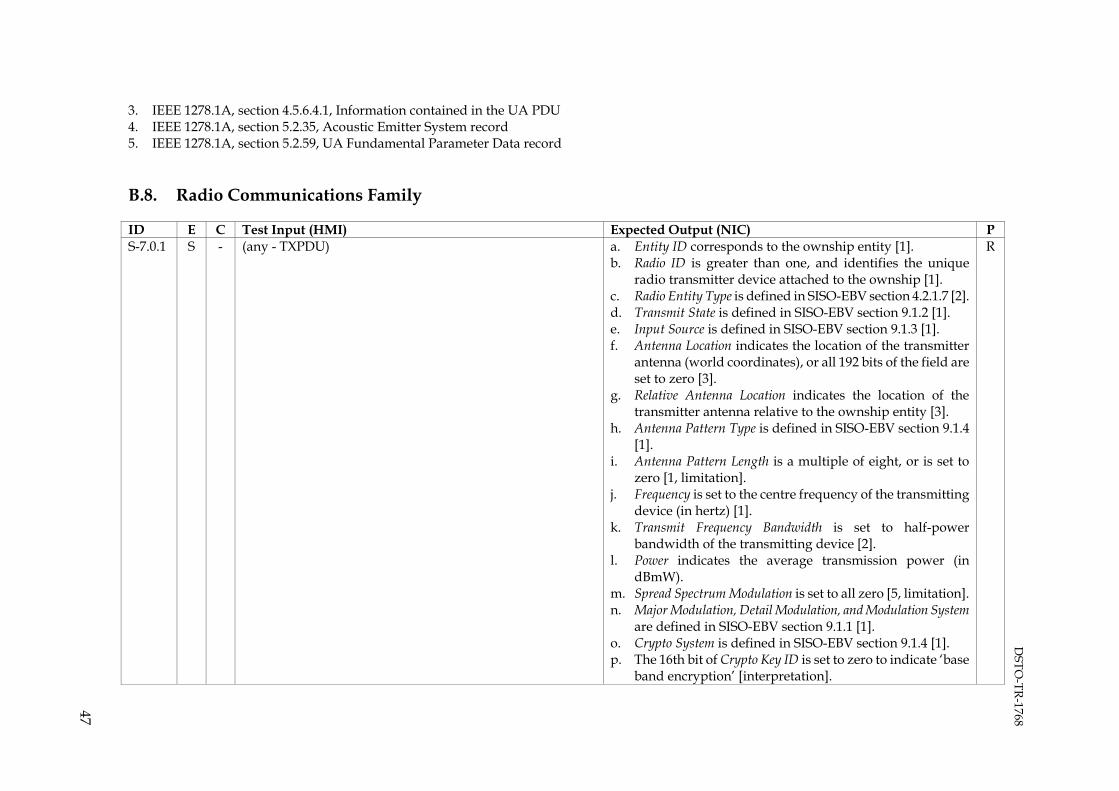
DSTO
-TR-1768
47
3. IEEE 1278.1A, section 4.5.6.4.1, Information contained in the UA PDU 4. IEEE 1278.1A, section 5.2.35, Acoustic Emitter System record 5. IEEE 1278.1A, section 5.2.59, UA Fundamental Parameter Data record B.8. Radio Communications Family
ID E C Test Input (HMI) Expected Output (NIC) P S-7.0.1 S - (any - TXPDU) a. Entity ID corresponds to the ownship entity [1].
b. Radio ID is greater than one, and identifies the unique radio transmitter device attached to the ownship [1].
c. Radio Entity Type is defined in SISO-EBV section 4.2.1.7 [2]. d. Transmit State is defined in SISO-EBV section 9.1.2 [1]. e. Input Source is defined in SISO-EBV section 9.1.3 [1]. f. Antenna Location indicates the location of the transmitter
antenna (world coordinates), or all 192 bits of the field are set to zero [3].
g. Relative Antenna Location indicates the location of the transmitter antenna relative to the ownship entity [3].
h. Antenna Pattern Type is defined in SISO-EBV section 9.1.4 [1].
i. Antenna Pattern Length is a multiple of eight, or is set to zero [1, limitation].
j. Frequency is set to the centre frequency of the transmitting device (in hertz) [1].
k. Transmit Frequency Bandwidth is set to half-power bandwidth of the transmitting device [2].
l. Power indicates the average transmission power (in dBmW).
m. Spread Spectrum Modulation is set to all zero [5, limitation]. n. Major Modulation, Detail Modulation, and Modulation System
are defined in SISO-EBV section 9.1.1 [1]. o. Crypto System is defined in SISO-EBV section 9.1.4 [1]. p. The 16th bit of Crypto Key ID is set to zero to indicate ‘base
band encryption’ [interpretation].
R

DSTO
-TR-1768
48
ID E C Test Input (HMI) Expected Output (NIC) P q. Length of Modulation Parameters is set to a multiple of eight
[1, limitation]. S-7.0.2 S - (any - Signal PDU) a. Entity ID indicates the ownship entity [6].
b. Radio ID is greater than one, and identifies the unique the radio transmitter device attached the ownship [6].
c. The Encoding Class and Encoding Type bits of Encoding Scheme are defined in SISO-EBV section 9.2 [6].
d. TDL Type is set to zero [6, limitation].
R
S-7.1 M C Configure the ownship and instructor/asset stations to transmit/receive communications on 8.125 MHz using Amplitude Modulation (AM). Set the crypto system to ‘KY-28’ and pseudo encryption key to 32767 (111111111111111b). Set the encoding scheme to 8-bit mu-law and sample rate to 8000 Hz.
N/A -
S-7.2 M T,C Create the ownship entity. Ensure that the entity is stationary, and that the radio transmitter/receiver is deactivated. Wait at least 15 seconds.
a. TXPDUs are sent at a five second heartbeat interval, or when the antenna location or elevation/azimuth thresholds have been exceeded (500 meters and 180 degrees respectively) [7]:
i. Transmitting State is set to ‘Off’. b. RXPDUs are sent at a five second heartbeat interval [8]:
i. Receiving State is set to ‘Off’.
R
S-7.3 M T Whilst stationary, activate the radio, but do not transmit. Wait at least 15 seconds.
a. TXPDUs are sent at a five second heartbeat interval, or when the antenna location, elevation/azimuth thresholds have been exceeded (500 meters and 180 degrees respectively) [7]:
i. Transmitting State is set to ‘On but not transmitting’. ii. Frequency is set to 8.125 MHz
iii. Major Modulation is set to ‘Amplitude’. iv. Minor Modulation is set to ‘AM’. v. Modulation System is set to ‘Generic’.
b. RXPDUs are sent at a five second heartbeat interval [8]: i. Receiving State is set to ‘On but not receiving’ or ‘On
and receiving’.
R
S-7.4 M T Whilst stationary, transmit plain audio for 15 seconds. a. At least one TXPDU is sent. R

DSTO
-TR-1768
49
ID E C Test Input (HMI) Expected Output (NIC) P i. Transmitting State is set to ‘On and transmitting’.
ii. Crypto System is set to zero and/or the lower 15-bits of Crypto Key ID are set to zero.
b. The simulator sends one or more Signal PDUs [9]. i. The Encoding Class bits of Encoding Scheme are set to
‘Encoded audio ‘ and the Encoding Scheme bits are set to ‘8-bit mu-law’.
ii. Sample Rate is set to 8000 Hz. iii. The encoded audio stored in Data corresponds to the
transmitted audio, is legible, and is at an appropriate volume level.
S-7.5 M T Manoeuvre the ownship to a moving state (e.g. constant velocity) for 10 seconds.
Apply test S-7.3 expected output, however the TXPDU heartbeat interval is two seconds.
R
S-7.6 M T Whilst moving, transmit plain audio for five seconds. Apply test S-7.4 expected output. R S-7.7 M T Whilst moving, switch to secure audio mode and wait for 15
seconds. a. TXPDUs are sent at a two second heartbeat interval, or
when the antenna location or elevation/azimuth thresholds have been exceeded (500 meters and 180 degrees respectively) [7].
i. Transmitting State is set to ‘Off’. ii. Frequency is set to 8.125 MHz
iii. Major Modulation is set to ‘Amplitude’. iv. Minor Modulation is set to ‘AM’. v. Modulation System is set to ‘Generic’.
vi. Crypto System is set to ‘KY-28’. vii. The lower 15-bits of Crypto Key ID are set to 32767.
c. The simulator sends one or more Signal PDUs [9]. i. The Encoding Class bits of Encoding Scheme are set to
‘Encoded audio ‘ and the Encoding Scheme bits are set to ‘8-bit mu-law’.
ii. Sample Rate is set to 8000 Hz. iii. The encoded audio stored in Data corresponds to the
transmitted audio, is legible, and is at an appropriate volume level.
R
S-7.8 M T Whilst moving, transmit secure audio for five seconds. Apply test S-7.4 expected output. R

DSTO
-TR-1768
50
ID E C Test Input (HMI) Expected Output (NIC) P S-7.9 M T Return the ownship to a stationary state and wait for 15
seconds. Apply test S-7.7 expected output, however the TXPDU heartbeat interval is five seconds.
R
S-7.10 M T Whilst stationary, transmit secure audio for five seconds. Apply test S-7.4 expected output. R Repeat - - Repeat test for FM modulation at 240.125 MHz. N/A - Repeat - - Repeat test for BFTT modulation at 240.125 MHz. N/A - Limitations 1. Simulator-specific antenna pattern and modulation parameter records are not tested. 2. Spread spectrum bitfields, such as those relevant to frequency hopping radios, are not tested. 3. Simulated tactical data links are not tested. References 1. IEEE 1278.1, section 5.3.8.1, Transmitter PDU 2. IEEE 1278.1, section 5.2.25, Radio Entity Type record 3. IEEE 1278.1, section 5.2.3, Antenna Location record 4. IEEE 1278.1, section 5.2.23, Modulation Type record 5. SISO-EBV, section 9.1.1.1, Spread Spectrum 6. IEEE 1278.1, section 5.3.8.2, Signal PDU 7. IEEE 1278.1, section 4.5.7.2.2, Issuance of the Transmitter PDU 8. IEEE 1278.1, section 4.5.7.4.2, Issuance of the Receiver PDU 9. IEEE 1278.1, section 4.5.7.3.2, Issuance of the Signal PDU
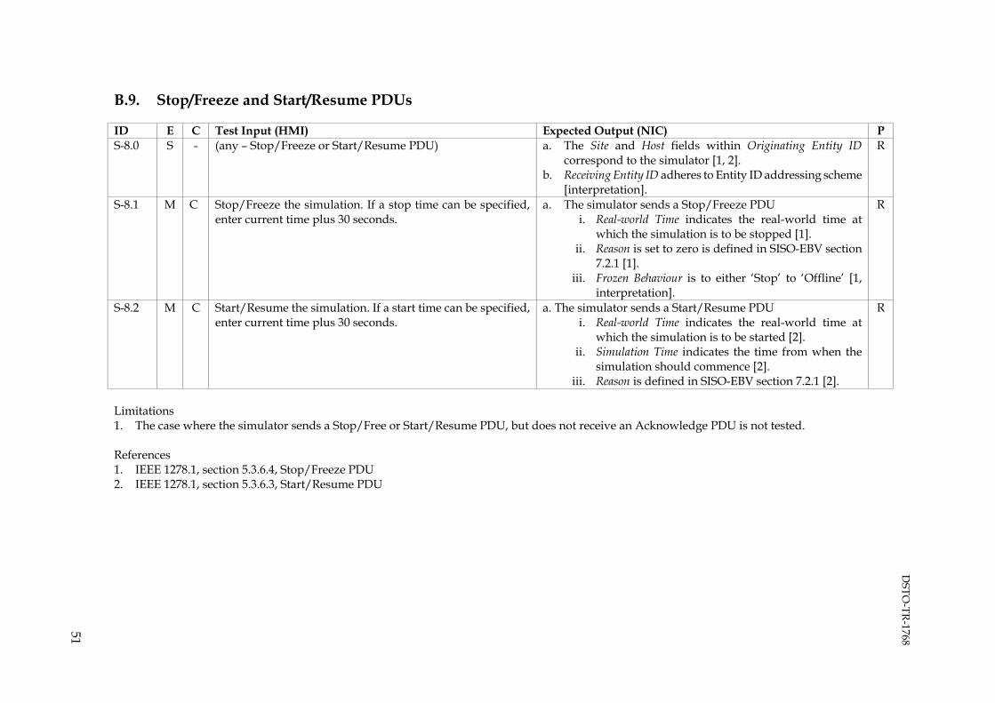
DSTO
-TR-1768
51
B.9. Stop/Freeze and Start/Resume PDUs
ID E C Test Input (HMI) Expected Output (NIC) P S-8.0 S - (any – Stop/Freeze or Start/Resume PDU) a. The Site and Host fields within Originating Entity ID
correspond to the simulator [1, 2]. b. Receiving Entity ID adheres to Entity ID addressing scheme
[interpretation].
R
S-8.1 M C Stop/Freeze the simulation. If a stop time can be specified, enter current time plus 30 seconds.
a. The simulator sends a Stop/Freeze PDU i. Real-world Time indicates the real-world time at
which the simulation is to be stopped [1]. ii. Reason is set to zero is defined in SISO-EBV section
7.2.1 [1]. iii. Frozen Behaviour is to either ‘Stop’ to ‘Offline’ [1,
interpretation].
R
S-8.2 M C Start/Resume the simulation. If a start time can be specified, enter current time plus 30 seconds.
a. The simulator sends a Start/Resume PDU i. Real-world Time indicates the real-world time at
which the simulation is to be started [2]. ii. Simulation Time indicates the time from when the
simulation should commence [2]. iii. Reason is defined in SISO-EBV section 7.2.1 [2].
R
Limitations 1. The case where the simulator sends a Stop/Free or Start/Resume PDU, but does not receive an Acknowledge PDU is not tested. References 1. IEEE 1278.1, section 5.3.6.4, Stop/Freeze PDU 2. IEEE 1278.1, section 5.3.6.3, Start/Resume PDU

DSTO
-TR-1768
52
B.10. Set Data or Comment PDU
ID E C Test Input (HMI) Expected Output (NIC) P S-9.0 S - (any – Set Data or Comment PDU) a. The Site and Host fields within Originating Entity ID
correspond to the simulator [1, 2]. b. Receiving Entity ID adheres with Entity ID addressing
scheme [interpretation]. c. For each fixed datum record:
i. Fixed Datum ID in defined in SISO-EBV section 7.1, or documented elsewhere [3].
d. For each variable datum record: i. Variable Datum ID is defined in SISO-EBV section
7.1, or documented elsewhere [4]. ii. Variable Datum Length indicates the length of the
variable datum value (in bits), and is a multiple of 64 [4].
R
S-9.1 S - (any – Comment PDU) e. Fixed Number of Fields is set to zero [2]. R Limitations 1. Specific datum values are not tested. References 1. IEEE 1278.1, section 5.3.6.9, Set Data PDU 2. IEEE 1278.1, section 5.3.6.12, Comment PDU 3. IEEE 1278.1, section 5.2.20, Fixed Datum record 4. IEEE 1278.1, section 5.2.32, Variable Datum record

DSTO
-TR-1768
53
B.11. Other Functionality
ID E C Test Input (HMI) Expected Output (NIC) P S-10.0 S - (any) a. If no PDUs are sent to convey the functionality, record the
implication for training in the test log. b. If a standard PDU is sent, apply the relevant test cases. c. If a non-standard PDU type is sent, ensure that its purpose
and usage documented, and that the PDU type does not conflict with existing non-standard PDU types.
R
S-10.1 - T,C Create the ownship entity. N/A - S-10.2 - T Launch chaff. N/A - S-10.3 - T Launch flares. N/A - S-10.4 - T Launch sonobuoys. N/A - S-10.5 - C Modify environmental conditions, for example, sea state or
wind speed. N/A -
B.12. Instructor/Asset Station
Repeat tests S-0 through S-10 for the instructor/asset stations; where an input action refers to the trainer component (T), use the instructor/asset station component (I). B.13. Stress Test
ID E C Test Input (HMI) Expected Output (NIC) P S-12.0 S - (any) All PDUs are transmitted at the correct heartbeat rate. R S-12.1 M T,C Create the ownship entity. N/A - S-12.2 M I Generate 250 entities, comprising a mixture of platform types.
All entities should have IFF, radar and/or sonar equipment activated.
All 250 entities are rendered. If the simulator imposes a limit on the number of entities it can generate, record this limit in the test log.
D

DSTO
-TR-1768
54
Appendix C: Test Cases for DIS Receive Testing
Unless stated, all PDUs are to be generated using the Version and Exercise ID set in the configuration testing stage. C.1. Entity State PDU
C.1.1 Entity State - Dead Reckoning
The purpose of this test is to ensure remote entities are rendered and that various dead reckoning algorithms are supported. ID E C Test Input (NIC) Expected Output (HMI) P R-1.1.0 S - (any) a. The simulator renders the remote entity [1].
b. The location of the remote entity rendered by the simulator corresponds to the described in the ESPDUs [1].
c. Symbology depicting the test entity platform and force ID is appropriate [1].
d. The dead-reckoned movement of the entity appears smooth and consistent [2].
R
R-1.1.1 M X Generate a test entity. The entity shall be orientated to the north and stationary for 12 seconds.
a. The simulator renders the orientation as north [1]. R
R-1.1.2 M X Move the test entity in a straight line at a constant velocity for 30 seconds.
N/A -
R-1.1.3 M X Move the test entity in a circular pattern for 30 seconds. N/A - Repeat - - Repeat for each dead reckoning algorithms. N/A - Repeat - - Repeat for each platform domain (land, air, sea) and force
orientations. N/A -

DSTO
-TR-1768
55
C.1.2 Entity State - Appearance
The purpose of this test is to demonstrate rendering of remote entity appearance bits. ID E C Test Input (NIC) Expected Output (HMI) P R-1.2.1 M X Generate a stationary test entity. Set the test entity Damage bits
of Appearance to ‘No damage’. Test entity is rendered as undamaged [1]. R
R-1.2.2 M X Set the test entity Damage bits of Appearance to ‘Slight damage’ or ‘Moderate damage’.
Test entity is rendered as destroyed or damaged [1]. D
R-1.2.3 M X Set the test entity Damage bits of Appearance to ‘Destroyed’. Test entity is rendered as destroyed [1]. D Repeat - - Repeat for each platform domain (land, air, sea) and force
orientations. N/A -
C.1.3 Entity State – Deactivation
This test demonstrates correct handling of deactivated entities. ID E C Test Input (NIC) Expected Output (HMI) P R-1.3.1 M X Generate a test entity and wait for 15 seconds. Test entity is rendered [1]. R R-1.3.2 M X Deactivate the test entity.
i. Send a final ESPDU with the State bit of Appearance set to ‘Deactivated’.
Immediately following deactivation the test entity is no longer rendered [1].
R

DSTO
-TR-1768
56
C.1.4 Entity State – Timeout
This test demonstrates receipt of entities that have timed out. ID E C Test Input (NIC) Expected Output (HMI) P R-1.4.1 M X Generate a test entity and wait for 15 seconds. Test entity is rendered [1]. R R-1.4.2 M X Deactivate the test entity and wait 12 seconds.
i. Do not send a final ESPDU. The test entity is no longer rendered [1]. R
C.1.5 Entity State – Frozen Entity
This test demonstrates receipt of frozen entities. ID E C Test Input (NIC) Expected Output (HMI) P R-1.5.1 M X Generate a test entity and wait for 15 seconds. Test entity is rendered [1]. R R-1.5.2 M X Set the test entity into a frozen state.
i. Continue to send ESPDUs with the Appearance field set to ‘Frozen’, and the State bit is set to ‘Activated’.
The test entity is no longer dead reckoned [3]. R
C.1.6 Entity State – Protocol Data Unit Header
This test demonstrates receipt of PDU header, when set to atypical values.
Limitations 1. Articulation parameters, which can be optionally included in the ESPDU, are not tested.
ID E C Test Input (HMI) Expected Output (NIC) P R-1.6.1 M X Generate a test entity with Protocol Version set to 4. The simulator renders the remote entity. D R-1.6.2 M X Generate a test entity with Protocol Version set to 5. The simulator renders the remote entity. D R-1.6.3 M X Generate a test entity with Exercise ID set to 2 (or any value
other than that currently sent by the simulator). The simulator does not render the remote entity [4]. R
R-1.6.4 M X Generate a test entity with Entity ID set to 0:0:0. The simulator does not render the remote entity [5]. D R-1.6.5 M X Generate a test entity with Entity ID set to 65535: 65535: 65535. The simulator does not render the remote entity [5]. D
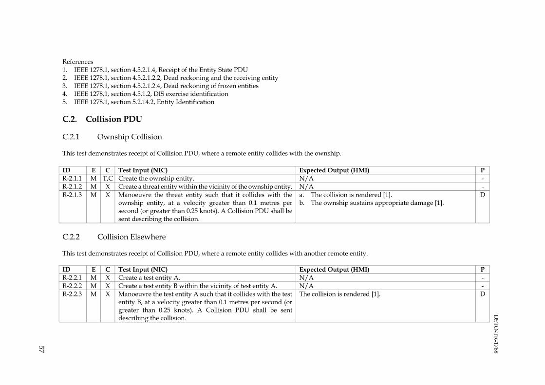
DSTO
-TR-1768
57
References 1. IEEE 1278.1, section 4.5.2.1.4, Receipt of the Entity State PDU 2. IEEE 1278.1, section 4.5.2.1.2.2, Dead reckoning and the receiving entity 3. IEEE 1278.1, section 4.5.2.1.2.4, Dead reckoning of frozen entities 4. IEEE 1278.1, section 4.5.1.2, DIS exercise identification 5. IEEE 1278.1, section 5.2.14.2, Entity Identification C.2. Collision PDU
C.2.1 Ownship Collision
This test demonstrates receipt of Collision PDU, where a remote entity collides with the ownship. ID E C Test Input (NIC) Expected Output (HMI) P R-2.1.1 M T,C Create the ownship entity. N/A - R-2.1.2 M X Create a threat entity within the vicinity of the ownship entity. N/A - R-2.1.3 M X Manoeuvre the threat entity such that it collides with the
ownship entity, at a velocity greater than 0.1 metres per second (or greater than 0.25 knots). A Collision PDU shall be sent describing the collision.
a. The collision is rendered [1]. b. The ownship sustains appropriate damage [1].
D
C.2.2 Collision Elsewhere
This test demonstrates receipt of Collision PDU, where a remote entity collides with another remote entity. ID E C Test Input (NIC) Expected Output (HMI) P R-2.2.1 M X Create a test entity A. N/A - R-2.2.2 M X Create a test entity B within the vicinity of test entity A. N/A - R-2.2.3 M X Manoeuvre the test entity A such that it collides with the test
entity B, at a velocity greater than 0.1 metres per second (or greater than 0.25 knots). A Collision PDU shall be sent describing the collision.
The collision is rendered [1]. D

DSTO
-TR-1768
58
References 1. IEEE 1278.1, section 4.5.2.2.4, Receipt of the Collision PDU C.3. Weapons
C.3.1 Weapons fired at Ownship
This test demonstrates receipt of the Fire and Detonation PDU, where a remote entity fires upon the ownship. ID E C Test Input (NIC) Expected Output (HMI) P R-3.1.1 M X Create a threat entity. N/A - R-3.1.2 M T,C Create the ownship entity with fire solution range of the threat
entity. N/A -
R-3.1.3 M X Fire a weapon from the threat entity at the ownship entity. The fire interaction is rendered by the simulator, at the location reported in the Fire PDU [1].
D
R-3.1.4 M X (weapon travel) If weapon is tracked, apply test R-1.1.0 (ESPDU) expected output to the weapon entity.
R-3.1.5 M X (weapon detonation) a. The detonation interaction is rendered by the simulator, at the location reported in the Detonation PDU [2].
b. The simulator responds appropriately to the detonation [2].
R
Repeat - - Repeat test for untracked weapons (where applicable). N/A - Repeat - - Repeat test, such that the weapon misses the simulator. N/A -
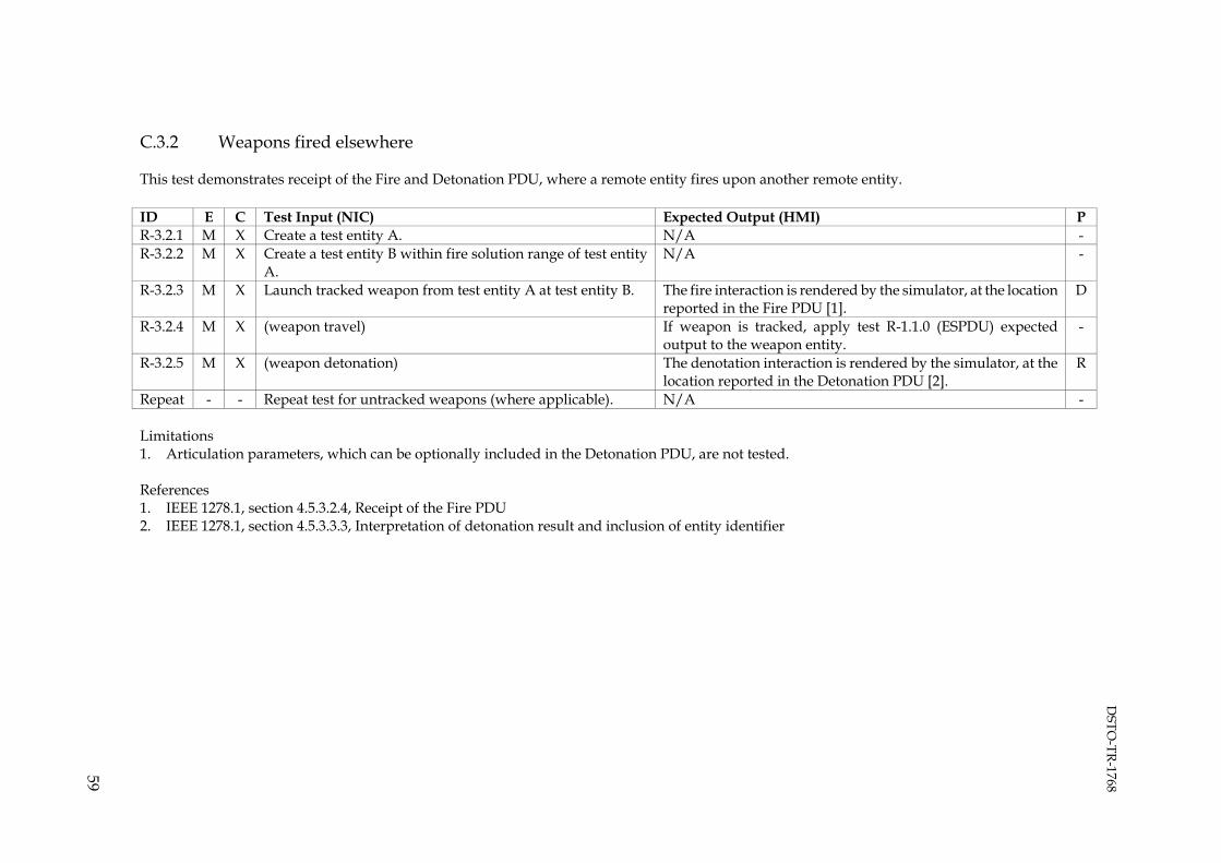
DSTO
-TR-1768
59
C.3.2 Weapons fired elsewhere
This test demonstrates receipt of the Fire and Detonation PDU, where a remote entity fires upon another remote entity. ID E C Test Input (NIC) Expected Output (HMI) P R-3.2.1 M X Create a test entity A. N/A - R-3.2.2 M X Create a test entity B within fire solution range of test entity
A. N/A -
R-3.2.3 M X Launch tracked weapon from test entity A at test entity B. The fire interaction is rendered by the simulator, at the location reported in the Fire PDU [1].
D
R-3.2.4 M X (weapon travel) If weapon is tracked, apply test R-1.1.0 (ESPDU) expected output to the weapon entity.
-
R-3.2.5 M X (weapon detonation) The denotation interaction is rendered by the simulator, at the location reported in the Detonation PDU [2].
R
Repeat - - Repeat test for untracked weapons (where applicable). N/A - Limitations 1. Articulation parameters, which can be optionally included in the Detonation PDU, are not tested. References 1. IEEE 1278.1, section 4.5.3.2.4, Receipt of the Fire PDU 2. IEEE 1278.1, section 4.5.3.3.3, Interpretation of detonation result and inclusion of entity identifier

DSTO
-TR-1768
60
C.4. Electromagnetic Emissions
Electromagnetic data is required to stimulate the simulator. As this data is dependent on the configuration of the simulator, it is described using arrowed brackets. C.4.1 Electromagnetic Emissions – State Update
This test demonstrates receipt of electromagnetic emissions. ID E C Test Input (NIC) Expected Output (HMI) P R-4.1.1 M X Generate a test entity within EW sensor range of the ownship
entity. No systems or beams are rendered. R
R-4.1.2 M X Activate the both emission systems and wait for 10 seconds. The first system (System A) shall indicate:
i. System Name is set to <System A-name>. ii. System Function is set to <System A-function>.
iii. System ID Number is set to 1. The first beam of the first system (Beam A1) shall indicate:
i. Beam ID Number is set to 1. ii. Beam Parameter Index is set to <Beam A1 index>.
iii. Beam Function is set to < Beam A1 function>. iv. The fundamental parameter data is set to < Beam
A1 data>. v. Number of Track/Jam Targets is set to the number of
tracked entities. vi. High Density Track/Jam is set to ‘Not Selected’.
The second beam of the first system (Beam A2) shall indicate: i. Beam ID Number is set to 2.
ii. Beam Parameter Index is set to <Beam A2 index>. iii. Beam Function is set to < Beam A2 function>. iv. The fundamental parameter data is set to < Beam
A2 data>.
All beams are rendered [1, 2]. R

DSTO
-TR-1768
61
ID E C Test Input (NIC) Expected Output (HMI) P v. Number of Track/Jam Targets is set to 0.
vi. High Density Track/Jam is set to ‘Not Selected’. The second system (System B) shall indicate:
i. System Name is set to <System B-name>. ii. System Function is set to <System B-function>.
iii. System ID Number is set to 2. The first beam of the second system (Beam B1) shall indicate:
i. Beam ID Number is set to 1. ii. Beam Parameter Index is set to <Beam B1 index>.
iii. Beam Function is set to <Beam B1 function>. iv. The fundamental parameter data is set to <Beam B1
data>. v. Number of Track/Jam Targets is set to 0.
vi. High Density Track/Jam is set to ‘Not Selected’. R-4.1.3 M X For at least one beam, track one or more entities. The beam
shall indicate: i. Number of Track/Jam Targets is set to N.
ii. High Density Track/Jam is set to ‘Not Selected’. iii. Specify entity IDs in the corresponding track/jam
target records.
Apply test R-4.1.2 expected output.
R-4.1.5 M X Deactivate the Beam A1 and wait 10 seconds. i. Set the Effective Radiated Power to zero for the second
beam of the first system.
The first beam of the first system is not rendered [1, 2]. R
R-4.1.6 M X Deactivate the Beam A1 and wait 10 seconds. i. Remove the first beam, of the first system, from the
EEPDU.
The first beam of the first system is not rendered [1, 2]. R
R-4.1.7 M X Deactivate System A. ii. Remove the second beam, of the first system, from
the EEPDU.
The second beam of the first system is not rendered [1, 2]. R
R-4.1.8 M X Deactivate the System A. iii. Remove the first system from the EEPDU.
Only system B is rendered [1, 2]. R
R-4.1.9 M X Deactivate the System B and wait 10 seconds. i. Send EEPDUs that contain no emission systems.
No systems or beams are rendered [1, 2]. R
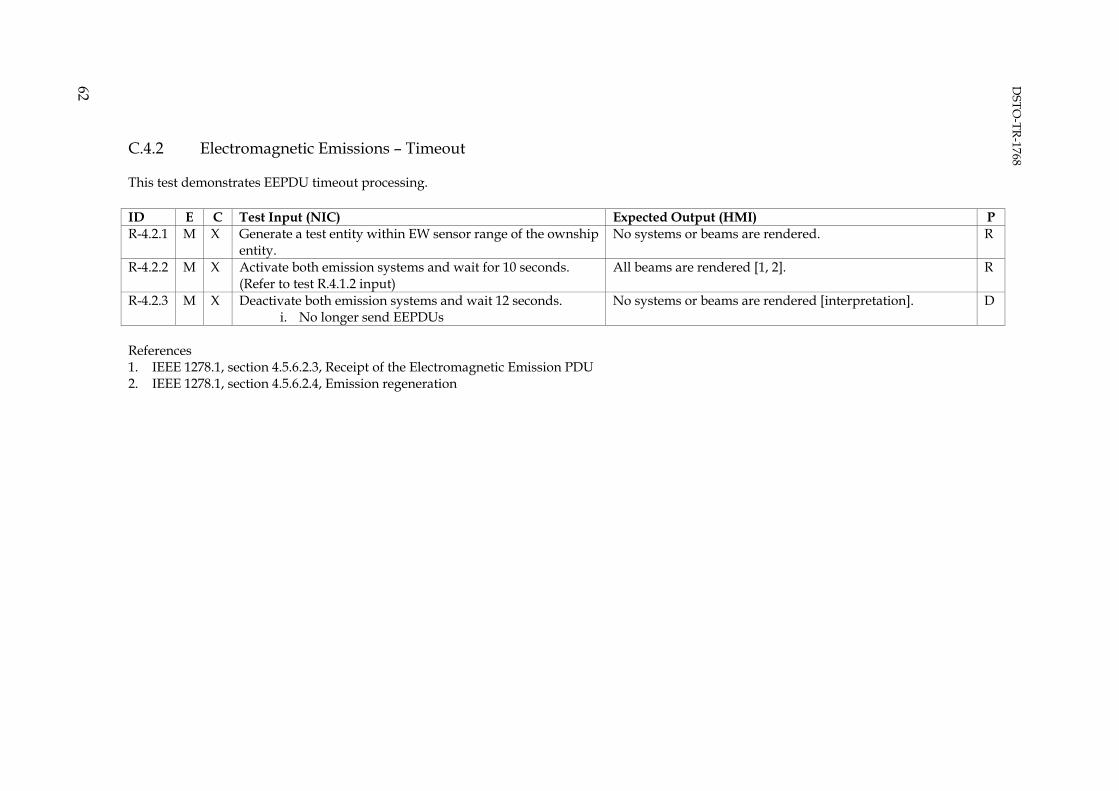
DSTO
-TR-1768
62
C.4.2 Electromagnetic Emissions – Timeout
This test demonstrates EEPDU timeout processing. ID E C Test Input (NIC) Expected Output (HMI) P R-4.2.1 M X Generate a test entity within EW sensor range of the ownship
entity. No systems or beams are rendered. R
R-4.2.2 M X Activate both emission systems and wait for 10 seconds. (Refer to test R.4.1.2 input)
All beams are rendered [1, 2]. R
R-4.2.3 M X Deactivate both emission systems and wait 12 seconds. i. No longer send EEPDUs
No systems or beams are rendered [interpretation]. D
References 1. IEEE 1278.1, section 4.5.6.2.3, Receipt of the Electromagnetic Emission PDU 2. IEEE 1278.1, section 4.5.6.2.4, Emission regeneration
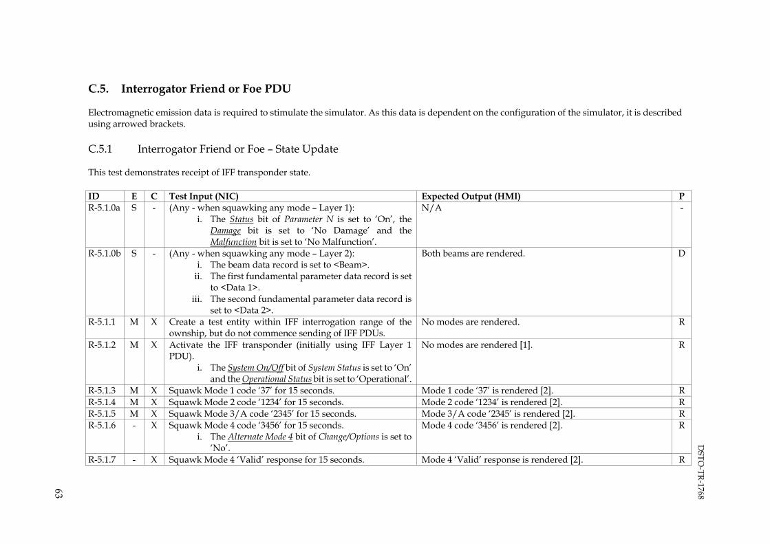
DSTO
-TR-1768
63
C.5. Interrogator Friend or Foe PDU
Electromagnetic emission data is required to stimulate the simulator. As this data is dependent on the configuration of the simulator, it is described using arrowed brackets. C.5.1 Interrogator Friend or Foe – State Update
This test demonstrates receipt of IFF transponder state. ID E C Test Input (NIC) Expected Output (HMI) P R-5.1.0a S - (Any - when squawking any mode – Layer 1):
i. The Status bit of Parameter N is set to ‘On’, the Damage bit is set to ‘No Damage’ and the Malfunction bit is set to ‘No Malfunction’.
N/A -
R-5.1.0b S - (Any - when squawking any mode – Layer 2): i. The beam data record is set to <Beam>.
ii. The first fundamental parameter data record is set to <Data 1>.
iii. The second fundamental parameter data record is set to <Data 2>.
Both beams are rendered. D
R-5.1.1 M X Create a test entity within IFF interrogation range of the ownship, but do not commence sending of IFF PDUs.
No modes are rendered. R
R-5.1.2 M X Activate the IFF transponder (initially using IFF Layer 1 PDU).
i. The System On/Off bit of System Status is set to ‘On’ and the Operational Status bit is set to ‘Operational’.
No modes are rendered [1]. R
R-5.1.3 M X Squawk Mode 1 code ‘37’ for 15 seconds. Mode 1 code ‘37’ is rendered [2]. R R-5.1.4 M X Squawk Mode 2 code ‘1234’ for 15 seconds. Mode 2 code ‘1234’ is rendered [2]. R R-5.1.5 M X Squawk Mode 3/A code ‘2345’ for 15 seconds. Mode 3/A code ‘2345’ is rendered [2]. R R-5.1.6 - X Squawk Mode 4 code ‘3456’ for 15 seconds.
i. The Alternate Mode 4 bit of Change/Options is set to ‘No’.
Mode 4 code ‘3456’ is rendered [2].
R
R-5.1.7 - X Squawk Mode 4 ‘Valid’ response for 15 seconds. Mode 4 ‘Valid’ response is rendered [2]. R

DSTO
-TR-1768
64
ID E C Test Input (NIC) Expected Output (HMI) P i. The Alternate Mode 4 bit of Change/Options is set to
‘Yes’. ii. The Code Element bits of Parameter 4 are set to all
ones. iii. Alternate Parameter 4 is set to ‘Valid’.
R-5.1.8 - X Repeat test R-5.7 input with ‘Invalid’ response. Mode 4 ‘Invalid’ response is rendered [2]. R R-5.1.9 - X Repeat test R-5.7 input with ‘No response’ Mode 4 ‘No response’ rendered [2]. R R-5.1.10 M X Squawk Mode Charlie for 15 seconds.
i. The Alternative Mode C bit of Change/Options is set to ‘No.’
ii. The Negative Altitude bit and Mode C Altitude bits of Parameter 5 indicate the altitude of the test entity.
The altitude reported in the IFFPDU is rendered [2]. R
R-5.1.11 M X Squawk Mode Charlie for 15 seconds. i. The Alternate Mode C bit of Change/Options is set to
‘Yes’ ii. The Negative Altitude bit and Mode C Altitude bits of
Parameter 5 are set to all ones.
The altitude reported in the ESPDU is rendered [2]. R
R-5.1.12 M X Squawk Identification/Flash for 15 seconds. i. The Ident/Squawk Flash bit of Modifier is set to ‘On’.
Identification/flash, Identification of Position (I/P) or Special Position Indicator is rendered.
R
R-5.1.13 M X Squawk Emergency mode for 15 seconds. i. Squawk Mode 3/A code ‘7700’.
ii. The Emergency bit of Modifier is set to ‘On’.
Emergency is rendered. R
Repeat - - Repeat test where the Operational Status bit of System Status is set to ‘System failed’.
No modes are rendered. R
Repeat - - Repeat test where the Damage bit of Parameter 1 through Parameter 6 is set to ‘Damage’.
No modes are rendered. R
Repeat - - Repeat test where the Malfunction bit of Parameter 1 through Parameter 6 is set to ‘Malfunction’.
No modes are rendered. R
Repeat - - Repeat test using IFF Layer 2 PDU. N/A -
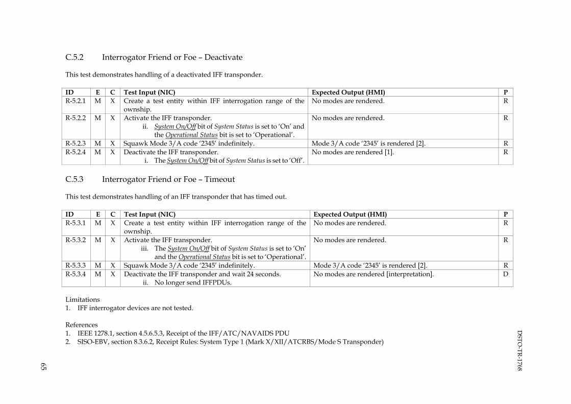
DSTO
-TR-1768
65
C.5.2 Interrogator Friend or Foe – Deactivate
This test demonstrates handling of a deactivated IFF transponder. ID E C Test Input (NIC) Expected Output (HMI) P R-5.2.1 M X Create a test entity within IFF interrogation range of the
ownship. No modes are rendered. R
R-5.2.2 M X Activate the IFF transponder. ii. System On/Off bit of System Status is set to ‘On’ and
the Operational Status bit is set to ‘Operational’.
No modes are rendered.
R
R-5.2.3 M X Squawk Mode 3/A code ‘2345’ indefinitely. Mode 3/A code ‘2345’ is rendered [2]. R R-5.2.4 M X Deactivate the IFF transponder.
i. The System On/Off bit of System Status is set to ‘Off’. No modes are rendered [1]. R
C.5.3 Interrogator Friend or Foe – Timeout
This test demonstrates handling of an IFF transponder that has timed out. ID E C Test Input (NIC) Expected Output (HMI) P R-5.3.1 M X Create a test entity within IFF interrogation range of the
ownship. No modes are rendered. R
R-5.3.2 M X Activate the IFF transponder. iii. The System On/Off bit of System Status is set to ‘On’
and the Operational Status bit is set to ‘Operational’.
No modes are rendered.
R
R-5.3.3 M X Squawk Mode 3/A code ‘2345’ indefinitely. Mode 3/A code ‘2345’ is rendered [2]. R R-5.3.4 M X Deactivate the IFF transponder and wait 24 seconds.
ii. No longer send IFFPDUs. No modes are rendered [interpretation]. D
Limitations 1. IFF interrogator devices are not tested. References 1. IEEE 1278.1, section 4.5.6.5.3, Receipt of the IFF/ATC/NAVAIDS PDU 2. SISO-EBV, section 8.3.6.2, Receipt Rules: System Type 1 (Mark X/XII/ATCRBS/Mode S Transponder)

DSTO
-TR-1768
66
C.6. Underwater Acoustic PDU
Underwater acoustic emission data is required to stimulate the simulator. As this data is dependent on the configuration of the simulator, it is described using arrowed brackets. C.6.1 Underwater Acoustic PDU – State Update
This test demonstrates receipt of underwater acoustic emissions. ID E C Test Input (NIC) Expected Output (HMI) P R-6.1.1 M X Create test entity within sonar range of the ownship. The passive acoustic signature is rendered [1, 2] R R-6.1.2 M X Change the passive acoustic signature. The new passive acoustic signature is rendered [1, 2] R R-6.1.3 M X Assigned the test entity a fixed speed and wait three minutes. Test entity shaft rate is rendered [1, 2]. R R-6.1.4 M X Increase the test entity to a speed and wait three minutes. Test entity shaft rate is rendered [1, 2]. R R-6.1.5 M X Decrease the test entity to a speed and wait three minutes. Test entity shaft rate is rendered [1, 2]. R R-6.1.6 M X Activate the emission systems and wait three minutes.
The first system (System A) shall indicate:
iv. Acoustic Name is set to <System A name>. v. Acoustic Function is set to <System A function>.
vi. Acoustic ID Number is set to 1. The first beam of the first system (Beam A1) shall indicate:
vii. Beam ID Number is set to 1. viii. Emission Parameter Index is set to <Beam A1 index>.
ix. The fundamental parameter data is set to <Beam A1 data>.
The second beam of the first system (Beam A2) shall indicate: vii. Beam ID Number is set to 2.
viii. Emission Parameter Index is set to <Beam A2 index>. ix. The fundamental parameter data is set to <Beam A2
data>. The second system (System B) shall indicate:
All three beams are rendered [1, 2].
R

DSTO
-TR-1768
67
ID E C Test Input (NIC) Expected Output (HMI) P vii. Acoustic Name is set to <System B name>.
viii. Acoustic Function is set to <System B function>. ix. Acoustic ID Number is set to 2.
The first beam of the second system (Beam B1) shall indicate: vii. Beam ID Number is set to 1.
viii. Emission Parameter Index is set to <Beam B1 index>. ix. The fundamental parameter data is set to <Beam B1
data>. R-6.1.7 M X Deactivate Beam A1. Wait three minutes. Beam A1 is no longer rendered [1, 2]. R R-6.1.8 M X Deactivate Beam A2, resulting in Number of Beams being set to
zero for System A. Wait three minutes. Beam A2 is no longer rendered [1, 2]. R
C.6.2 Underwater Acoustic PDU – Timeout
This test demonstrates UAPDU timeout processing. ID E C Test Input (NIC) Expected Output (HMI) P R-6.2.1 M X Create test entity within sensor range of the ownship. N/A - R-6.2.2 M X Assign the test entity a fixed speed and wait three minutes. Shaft rates are rendered [1, 2]. R R-6.2.3 M X Apply test R-6.1.5 input. All three beams are rendered [1, 2]. R R-6.2.4 M X Deactivate both emission systems and wait 432 seconds.
i. No longer send UAPDUs. No shafts or beams are rendered [interpretation]. D
References 1. Additional passive activity records are not tested References 1. IEEE 1278.1, section 4.5.6.4.3, Receipt of the UA PDU 2. IEEE 1278.1, section 4.5.6.4.4, UA emission regeneration
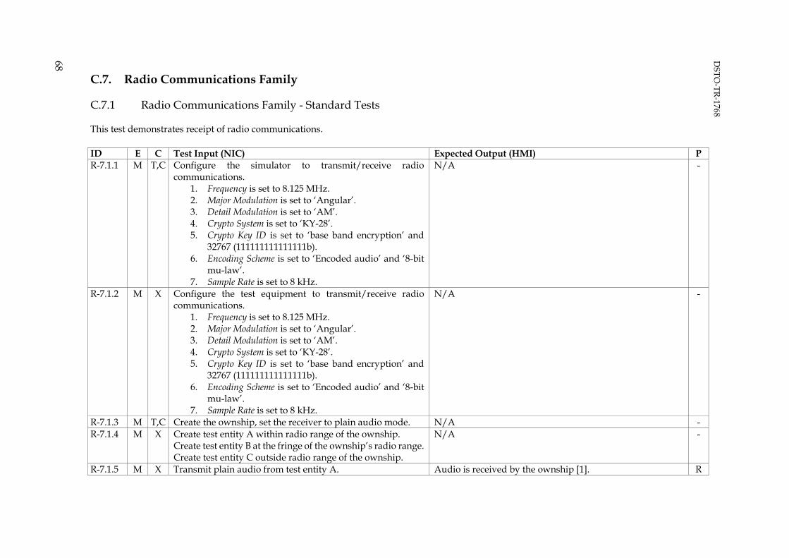
DSTO
-TR-1768
68
C.7. Radio Communications Family
C.7.1 Radio Communications Family - Standard Tests
This test demonstrates receipt of radio communications. ID E C Test Input (NIC) Expected Output (HMI) P R-7.1.1 M T,C Configure the simulator to transmit/receive radio
communications. 1. Frequency is set to 8.125 MHz. 2. Major Modulation is set to ‘Angular’. 3. Detail Modulation is set to ‘AM’. 4. Crypto System is set to ‘KY-28’. 5. Crypto Key ID is set to ‘base band encryption’ and
32767 (111111111111111b). 6. Encoding Scheme is set to ‘Encoded audio’ and ‘8-bit
mu-law’. 7. Sample Rate is set to 8 kHz.
N/A -
R-7.1.2 M X Configure the test equipment to transmit/receive radio communications.
1. Frequency is set to 8.125 MHz. 2. Major Modulation is set to ‘Angular’. 3. Detail Modulation is set to ‘AM’. 4. Crypto System is set to ‘KY-28’. 5. Crypto Key ID is set to ‘base band encryption’ and
32767 (111111111111111b). 6. Encoding Scheme is set to ‘Encoded audio’ and ‘8-bit
mu-law’. 7. Sample Rate is set to 8 kHz.
N/A -
R-7.1.3 M T,C Create the ownship, set the receiver to plain audio mode. N/A - R-7.1.4 M X Create test entity A within radio range of the ownship.
Create test entity B at the fringe of the ownship’s radio range. Create test entity C outside radio range of the ownship.
N/A -
R-7.1.5 M X Transmit plain audio from test entity A. Audio is received by the ownship [1]. R

DSTO
-TR-1768
69
ID E C Test Input (NIC) Expected Output (HMI) P i. Antenna Location is set to the test entity location.
R-7.1.6 M X Transmit plain audio from test entity A. i. Antenna Location is set to (0, 0, 0).
Audio is received by the ownship [1].
R
R-7.1.7 M X Transmit plain audio from test entity A, where all padding field bits are set to 1.
Audio is received by the ownship [1]. R
R-7.1.8 M X Transmit plain audio, where the transmission is not associated with an entity in the exercise.
Audio is received by the ownship [1]. R
R-7.1.9 M X Transmit plain audio from test entity B. Audio is distorted or not received by the ownship, [1].
R
R-7.1.10 M X Transmit plain audio from test entity C. Audio is not received by the ownship, due to the transmitter being out of range of the receiver [1]. If audio is received by the ownship, record “simulator does not model propagation effects” in the test log.
D
R-7.1.11 M X Transmit secure audio from test entity A. Leave the ownship receiver in plain mode.
Audio is not received by the ownship [1]. If audio is received by the ownship, record “simulator renders secure audio in plain mode” in the test log.
D
R-7.1.12 M T Set the ownship receiver to secure audio mode. N/A - R-7.1.13 M X Transmit secure audio from test entity A.
i. Antenna Location is set to the test entity location. Audio is received by the ownship [1]. R
R-7.1.14 M X Transmit secure audio from test entity A i. Antenna Location is set to (0, 0, 0).
Audio is received by the ownship [1]. R
R-7.1.15 M X Transmit secure audio from test entity B. Audio is distorted or not received by the ownship [1]. R R-7.1.16 M X Transmit secure audio from test entity C. Audio is not received by ownship [1]. R R-7.1.17 M X Transmit plain audio from test entity A. N/A
If audio is received by the ownship, record “simulator renders plain audio when operating in secure mode” in the test log.
-
R-7.1.18 M X Modify the test equipment configuration. 1. Frequency is set to 8.125 MHz + 1 Hz. 2. Major Modulation is set to ‘Angular’. 3. Detail Modulation is set to ‘AM’.
Transmit plain audio from entity A.
Audio is received by the ownship [1]. If no audio is received by the ownship, record “simulator requires exact centre frequency match” in the test log.
R

DSTO
-TR-1768
70
ID E C Test Input (NIC) Expected Output (HMI) P R-7.1.19 M X Modify the test equipment configuration.
4. Frequency is set to 8.126 MHz + 25 kHz. 5. Major Modulation is set to ‘Angular’. 6. Detail Modulation is set to ‘AM’.
Transmit plain audio from entity A.
Audio is distorted or not received by the ownship [1].
R
Repeat - - Repeat test using FM modulation at 240.125 MHz. N/A - Repeat - - Repeat test using BFTT modulation at 240.125 MHz. N/A - C.7.2 Radio Communications Family – Pseudo Encryption Capability
This test further demonstrates receipt of pseudo encrypted radio communications. ID E C Test Input (NIC) Expected Output (HMI) P R-7.2.1 M X Repeat test R-7.1.1 through R-7.1.4 input N/A - R-7.2.2 M X Modify the test equipment configuration.
1. Frequency is set to 8.125 MHz. 2. Major Modulation is set to ‘Angular’. 3. Detail Modulation is set to ‘AM’. 4. Crypto System is set to ‘KY-28’. 5. Crypto Key ID is set to ‘base band encryption’ and
21845 (101010101010101b). Transmit secure audio from test entity A.
Audio is not received, due to the Crypto Key ID not matching that expected by the ownship receiver [2]. If audio is received by the ownship, record “simulator ignores Crypto Key ID value” in the test log.
D
R-7.2.3 M X Modify the test equipment configuration. 1. Frequency is set to 8.125 MHz. 2. Major Modulation is set to ‘Angular’. 3. Detail Modulation is set to ‘AM’. 4. Crypto System is set to ‘KY-58’. 5. Crypto Key ID is set to ‘base band encryption’ and
32767 (111111111111111b). Transmit secure audio from test entity A.
Audio is not received, due to the Crypto System not matching that expected by the ownship receiver [2]. If audio is received by the ownship, record “simulator ignores Crypto System value” in the test log.
D
R-7.2.4 M X Modify the test equipment configuration. 1. Frequency is set to 8.125 MHz. 2. Major Modulation is set to ‘Angular’. 3. Detail Modulation is set to ‘AM’.
Audio is not received, due to the Crypto System not matching that expected by the ownship receiver [2]. If audio is received by the ownship, record “simulator renders
D

DSTO
-TR-1768
71
ID E C Test Input (NIC) Expected Output (HMI) P 4. Crypto System is set to ‘Other’. 5. Crypto Key ID is set to ‘base band encryption’ and
32767 (111111111111111b). Transmit secure audio from test entity A.
‘Other’ Crypto System value” in the test log.
R-7.2.5 M X Modify the test equipment configuration. 1. Frequency is set to 8.125 MHz. 2. Major Modulation is set to ‘Angular’. 3. Detail Modulation is set to ‘AM’. 4. Crypto System is set to 127 (a non-standard value). 5. Crypto Key ID is set to ‘base band encryption’ and
32767 (111111111111111b). Transmit secure audio from test entity A.
Audio is not received, due to the Crypto System not matching that expected by the ownship receiver [2]. If audio is received by the ownship, record “simulator renders non-standard Crypto System value” in the test log.
D
C.7.3 Radio Communications Family - Modulation Tests
ID E C Test Input (NIC) Expected Output (HMI) P R-7.3.1 M X Repeat test R-7.1.1 through R-7.1.4 input N/A - R-7.3.2 M X Modify the test equipment configuration to transmit/receive
communications. 1. Frequency is set to 8.125 MHz. 2. Major Modulation is set to 2. 3. Detail Modulation is set to 2.
Transmit plain audio from test entity A.
Audio is distorted or not received, due to Major Modulation and Minor Modulation not matching the values entered into the simulators configuration [1]. If audio is received by the ownship, record ”simulator ignores Major Modulation and Detail Modulation fields” in the test log.
R
References 1. IEEE 1278.1, section 4.5.7.2.3, Receipt of the Transmitter PDU 2. IEEE 1278.1, section 4.5.7.2.1, Information contained in the Transmitter PDU
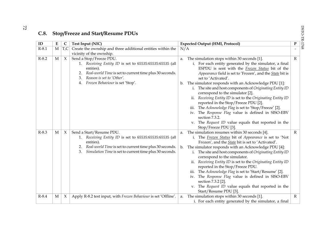
DSTO
-TR-1768
72
C.8. Stop/Freeze and Start/Resume PDUs
ID E C Test Input (NIC) Expected Output (HMI, Protocol) P R-8.1 M T,C Create the ownship and three additional entities within the
vicinity of the ownship. N/A -
R-8.2 M X Send a Stop/Freeze PDU. 1. Receiving Entity ID is set to 65535:65535:65535 (all
entities). 2. Real-world Time is set to current time plus 30 seconds. 3. Reason is set to ‘Other’. 4. Frozen Behaviour is set ‘Stop’.
a. The simulation stops within 30 seconds [1]. i. For each entity generated by the simulator, a final
ESPDU is sent with the Frozen Status bit of the Appearance field is set to ‘Frozen’, and the State bit is set to ‘Activated’.
b. The simulator responds with an Acknowledge PDU [1]: i. The site and host components of Originating Entity ID
correspond to the simulator [2]. ii. Receiving Entity ID is set to the Originating Entity ID
reported in the Stop/Freeze PDU [2]. iii. The Acknowledge Flag is set to ‘Stop/Freeze’ [2]. iv. The Response Flag value is defined in SISO-EBV
section 7.3.2. v. The Request ID value equals that reported in the
Stop/Freeze PDU [3].
R
R-8.3 M X Send a Start/Resume PDU. 1. Receiving Entity ID is set to 65535:65535:65535 (all
entities). 2. Real-world Time is set to current time plus 30 seconds. 3. Simulation Time is set to current time plus 30 seconds.
a. The simulation resumes within 30 seconds [4]. i. The Frozen Status bit of Appearance is set to ‘Not
Frozen’, and the State bit is set to ‘Activated’. b. The simulator responds with an Acknowledge PDU [4]:
i. The site and host components of Originating Entity ID correspond to the simulator.
ii. Receiving Entity ID is set to the Originating Entity ID reported in the Stop/Freeze PDU.
iii. The Acknowledge Flag is set to ‘Start/Resume’ [2]. iv. The Response Flag value is defined in SISO-EBV
section 7.3.2 [2]. v. The Request ID value equals that reported in the
Start/Resume PDU [3].
R
R-8.4 M X Apply R-8.2 test input, with Frozen Behaviour is set ‘Offline’. a. The simulation stops within 30 seconds [1]. i. For each entity generated by the simulator, a final
R

DSTO
-TR-1768
73
ID E C Test Input (NIC) Expected Output (HMI, Protocol) P ESPDUs is sent with the State bit of Appearance set to ‘Deactivated’.
b. The simulator responds with an Acknowledge PDU [1]: i. The site and host components of Originating Entity ID
correspond to the simulator [2]. ii. Receiving Entity ID is set to the Originating Entity ID
reported in the Stop/Freeze PDU [2]. iii. The Acknowledge Flag is set to ‘Stop/Freeze’ [2]. iv. The Response Flag value is defined in SISO-EBV
section 7.3.2 [2]. v. The Request ID value equals that reported in the
Stop/Freeze PDU [3]. R-8.5 M X Apply R-8.3 test input. Apply R-8.3 expected output. - Repeat - - Repeat test, with Receiving Entity ID to 0:0:0 N/A - Repeat - - Repeat test, with Receiving Entity ID to SITE:HOST:65535 N/A - Repeat - - Repeat test, with Receiving Entity ID to SITE:HOST:0 N/A - References 1. IEEE 1278.1, section 4.5.5.4.4.4, Receipt of the Stop/Freeze PDU 2. IEEE 1278.1, section 5.3.6.5, Acknowledge PDU 3. IEEE 1278.1, section 4.5.5.4.5.1, Information contained in the Acknowledge PDU 4. IEEE 1278.1, section 4.5.5.4.3.3 Receipt of the Start/Resume PDU

DSTO
-TR-1768
74
C.9. Set Data, Comment and Other PDUs
This test demonstrates graceful handling of Set Data, Command and other standard or non-standard PDUs. ID E C Test Input (NIC) Expected Output (HMI) P R-9.0 S - (any) Simulator exhibits no adverse behaviour. R R-9.1 M X Send Set Data and Comment PDUs:
i. Receiving Entity ID is set to 65535:65535:65535. N/A -
R-9.1. M Send Set Data and Comment PDUs: i. Receiving Entity ID is set to 0:0:0.
N/A -
R-9.2 M X Generate all standard PDUs. N/A - R-9.3 M X Generate PDUs with valid headers, but containing otherwise
random data, for PDU types 129 through 255. N/A -
C.10. Stress Test
This test measures performance degradation whilst the simulator processes a large number of remote entities. Degradation is calculated by monitoring ownship heartbeat interval and the responsiveness of the trainer, instructor and control station HMIs. ID E C Test Input (NIC) Expected Output (HMI) P R-10.0 S - (any) a. ESPDUs are describing the ownship and scenario role-
player entities are sent at a constant heartbeat interval. b. The trainer, instructor and control station HMIs are
responsive.
R
R-10.1 M T,C Create the ownship entity and manoeuvre it into a stationary or constant velocity state.
N/A -
R-10.2 M I Create one scenario role-player entity and manoeuvre it into a stationary or constant velocity state.
N/A -
R-10.3 M X Generate 250 entities within the test area, where each moves in a circular pattern and each is assigned electromagnetic and acoustic emissions, and IFF.
a. All 250 entities are rendered. If the simulator imposes a limit on the number of entities received, record this limit in the test log.
R
R-10.4 M X Playback a log file recording from a prior training exercise. a. All entities are rendered. R
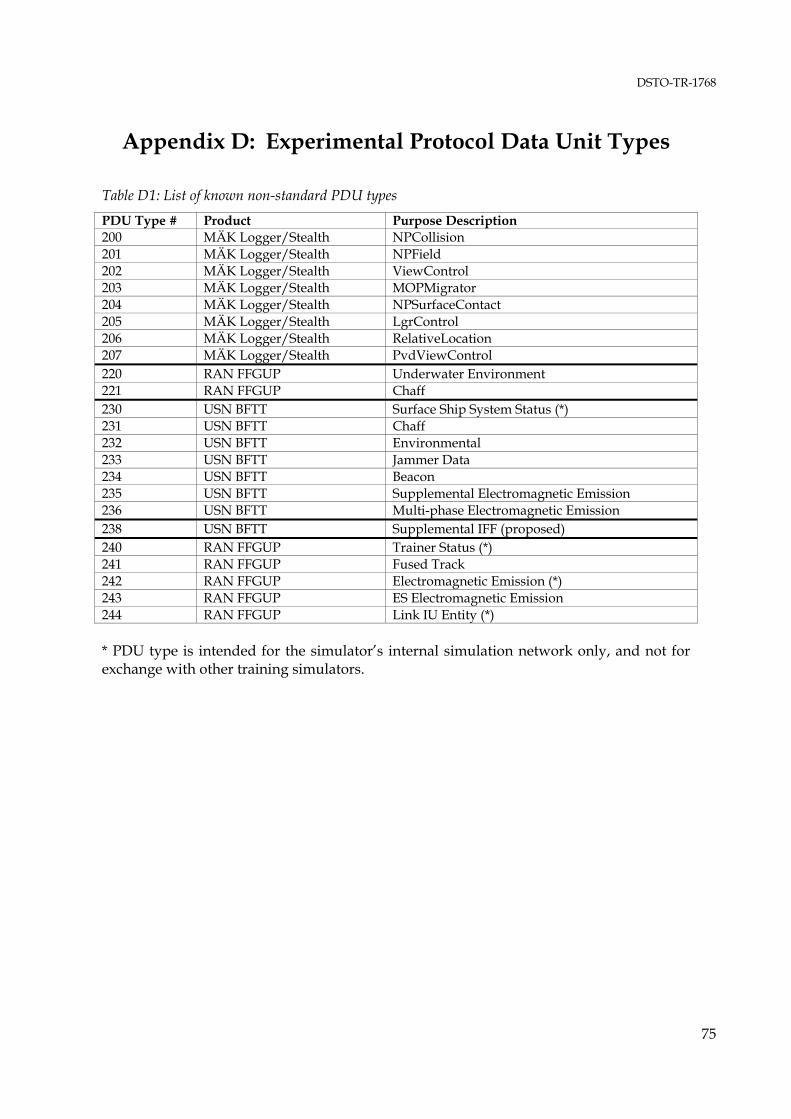
DSTO-TR-1768
75
Appendix D: Experimental Protocol Data Unit Types
Table D1: List of known non-standard PDU types
PDU Type # Product Purpose Description 200 MÄK Logger/Stealth NPCollision 201 MÄK Logger/Stealth NPField 202 MÄK Logger/Stealth ViewControl 203 MÄK Logger/Stealth MOPMigrator 204 MÄK Logger/Stealth NPSurfaceContact 205 MÄK Logger/Stealth LgrControl 206 MÄK Logger/Stealth RelativeLocation 207 MÄK Logger/Stealth PvdViewControl 220 RAN FFGUP Underwater Environment 221 RAN FFGUP Chaff 230 USN BFTT Surface Ship System Status (*) 231 USN BFTT Chaff 232 USN BFTT Environmental 233 USN BFTT Jammer Data 234 USN BFTT Beacon 235 USN BFTT Supplemental Electromagnetic Emission 236 USN BFTT Multi-phase Electromagnetic Emission 238 USN BFTT Supplemental IFF (proposed) 240 RAN FFGUP Trainer Status (*) 241 RAN FFGUP Fused Track 242 RAN FFGUP Electromagnetic Emission (*) 243 RAN FFGUP ES Electromagnetic Emission 244 RAN FFGUP Link IU Entity (*) * PDU type is intended for the simulator’s internal simulation network only, and not for exchange with other training simulators.

DISTRIBUTION LIST
Recommended Acceptance Testing Procedure for Network Enabled Training Simulators
Peter Ross and Peter Clark
DEFENCE ORGANISATION
No. of copies Task Sponsor CDRE Drew McKinnie, DGMSS
1 Printed
S&T Program
Chief Defence Scientist 1 Deputy Chief Defence Scientist Policy 1 AS Science Corporate Management 1 Director General Science Policy Development 1 Counsellor Defence Science, London Doc Data Sheet Counsellor Defence Science, Washington Doc Data Sheet Scientific Adviser to MRDC, Thailand Doc Data Sheet Scientific Adviser Joint 1 Navy Scientific Adviser 1 Scientific Adviser – Army 1 Air Force Scientific Adviser 1 Scientific Adviser to the DMO – Mr Kevin Bly 1 Assistant Scientific Adviser to the DMO – Mr Rick Dykstra 1 CAOD 1 Printed RL-CET 1 Printed RL-AOA 1 Printed RL-AMS 1 Printed Dr Peter Ryan, HSTA 1 Printed Dr James Meehan, HATR 1 Printed Mr Jon Blacklock, HAPS 1 Printed HAOSC 1 Printed Dr Peter Clark (author) 10 Printed Mr Peter Ross (author) 10 Printed Mr Andrew Robbie 1 Printed Mr Graeme Simpkin 1 Printed CMOD 1 Printed Dr John Riley, RL-MCS, MOD-Edinburgh 1 Printed Dr Chris Davis, RL-MOR, MOD-Stirling 1 Printed Dr David Gamble, HUWA, MOD-Stirling 1 Printed Dr Maurice Battaglia, HMTC, MOD-Pyrmont 1 Printed Dr John Wendoloski, MOD-Pyrmont 1 Printed

CLOD Dr Anne-Marie Grisogono, RL-LS, LOD 1 Printed Dr Jon Vaughan, HCDS, LOD 1 Printed Mr Ion Menadue, LOD 1 Printed Kevin Gaylor, HUPS, MPD 1 Printed John Wharington, MPD 1 Printed DSTO Library and Archives
Library Fishermans Bend 1 Printed Library Edinburgh 1 Printed Defence Archives 1 Printed Defence Materiel Organisation
Mr Mal Adams, FFG SPO Director 1 Printed CMDR Robert Richardson, CSM SEA 1390 1 Printed LEUT Andrew Payne, SEA1390 1 Printed Mr Max Britton, FFG SPO 1 Printed Mr Mark Fairleigh, DASSPA 1 Printed Mr Ralph Wittwer, DDASSPA; AP-3C AFS Project Manager 1 Printed Mr Luke Hartfiel, HACTS Project Manager 1 Printed Mr Paul Norris, ALS Project Manager 1 Printed Mr Cameron Stewart, Air to Air Refuelling Project, Logistics Manager 1 Printed Mr Philip Linke, AEW&C OFT RPT, PO BOX 3999, Seattle, WA 98124,
USA 1 Printed
Mr Kevin Bailey, AIR 9000 Ph 2, Logistics Manager 1 Printed Mr Di Tung Wong, PS1411 Ground Based Systems, Navy Aviation Project
Office, HMAS Albatross 1 Printed
Mr John Shaw, DMCP (Navy), CP4-3-040 1 Printed Capability Development Group
Director General Aerospace Development Doc Data Sheet GPCAPT Glen Nattrass, DASD 1 Printed Director General Maritime Development Doc Data Sheet Director General Land Development Doc Data Sheet Mr Cliff White, DG-Simulation 1 Printed Mr John Loughhead, ADSO-Army 1 Printed WGCDR Tom Wickham, ADSO-Air Force 1 Printed Mr Darren McFarlane, ADSO-Navy 1 Printed ADSO-Joint 1 Printed Air Force
SO (Science) - Headquarters Air Combat Group, RAAF Williamtown Doc Data Sheet & Exec Sum.
AIRCDRE Tim Owen, CDRSRG, RAAF Williamtown 1 Printed WGCDR Phil Lavelle, SOCD(Maritime), SRG, RAAF Williamtown 1 Printed SQNLDR Warren Hutchinson, OIC AP-3C AFS, 292 SQN, RAAF 1 Printed

Edinburgh FLTLT Matthew Stuckless, OIC AP-3C OMS, 292 SQN, RAAF Edinburgh 1 Printed SQNLDR Carl Zell, AEW&C OMS RPT, 2 SQN, RAAF Williamtown 1 Printed SQNLDR Jamie Minor, C130H SIMFIDMGR, 285 SQN, RAAF Richmond 1 Printed WGCDR Chris Middleton, SODGNACC 1 Printed Navy
SO (SCIENCE), COMAUSNAVSURFGRP, NSW Doc Data Sheet & Dist List
CDRE Nigel Coates, DGNPT 1 Printed CAPT Ian Middleton, CO TAMW, HMAS WATSON 1 Printed CMDR Ralph McDonald, TAMW, HMAS WATSON 1 Printed CMDR Larry Menon, HCS TAMW, HMAS WATSON 1 Printed CMDR Peter Quinn, CO HMAS SYDNEY 1 Printed Mr Beng Ooi, AD-CMS, NWSA 1 Printed Army
ABCA National Standardisation Officer, Land Warfare Development Sector, Puckapunyal
e-mailed Doc Data Sheet
SO (Science) - Land Headquarters (LHQ), Victoria Barracks NSW Doc Data Sheet & Exec Sum.
SO (Science), Deployable Joint Force Headquarters (DJFHQ) (L), Enoggera QLD
Doc Data Sheet
Director, Army Simulation Office, Puckapunyal 1 Printed HQAST
Mr Grant Robinson, ADFWC, RAAF Williamtown 1 Printed Intelligence and Security Group
DGSTA Defence Intelligence Organisation 1 Manager, Information Centre, Defence Intelligence Organisation 1 Defence Libraries
Library Manager, DLS-Canberra 1
OUTSIDE AUSTRALIA
INTERNATIONAL DEFENCE INFORMATION CENTRES US Defense Technical Information Center 1 UK Dstl Knowledge Services 1 Canada Defence Research Directorate R&D Knowledge & Information
Management (DRDKIM) 1
NZ Defence Information Centre 1 SPARES 5 Total number of copies: 98 Printed: 85 PDF: 14

Page classification: UNCLASSIFIED
DEFENCE SCIENCE AND TECHNOLOGY ORGANISATION
DOCUMENT CONTROL DATA 1. PRIVACY MARKING/CAVEAT (OF DOCUMENT)
2. TITLE Recommended Acceptance Testing Procedure for Network Enabled Training Simulators
3. SECURITY CLASSIFICATION (FOR UNCLASSIFIED REPORTS THAT ARE LIMITED RELEASE USE (L) NEXT TO DOCUMENT CLASSIFICATION) Document (U) Title (U) Abstract (U)
4. AUTHOR(S) Peter Ross and Peter Clark
5. CORPORATE AUTHOR DSTO Defence Science and Technology Organisation 506 Lorimer St Fishermans Bend Victoria 3207 Australia
6a. DSTO NUMBER DSTO-TR-1768
6b. AR NUMBER AR-013-491
6c. TYPE OF REPORT Technical Report
7. DOCUMENT DATE August 2005
8. FILE NUMBER 2003/36056
9. TASK NUMBER NAV 04/026
10. TASK SPONSOR DMO - DGMSS
11. NO. OF PAGES 75
12. NO. OF REFERENCES 29
13. URL on the World Wide Web http://www.dsto.defence.gov.au/corporate/reports/DSTO-TR1768.pdf
14. RELEASE AUTHORITY Chief, Air Operations Division
15. SECONDARY RELEASE STATEMENT OF THIS DOCUMENT
Approved for public release OVERSEAS ENQUIRIES OUTSIDE STATED LIMITATIONS SHOULD BE REFERRED THROUGH DOCUMENT EXCHANGE, PO BOX 1500, EDINBURGH, SA 5111 16. DELIBERATE ANNOUNCEMENT No Limitations 17. CITATION IN OTHER DOCUMENTS Yes 18. DEFTEST DESCRIPTORS Distributed Interactive Simulation; Guided missile frigates; Human-in-the-Loop simulation; Interoperability; Military equipment upgrades; Military team training; Software engineering; Synthetic environments 19. ABSTRACT Over the next ten years the Department of Defence will acquire many new platform training simulators that will support distributed team training, otherwise known as network-enabled training simulators. These include the AP-3C Operational Mission Simulator and Advanced Flight Simulator, Airborne Early Warning & Control Operational Mission Simulator, C-130H and C-130J flight simulators, Armed Reconnaissance Helicopter (ARH) simulator, Super Seasprite simulator, and FFG Upgrade Onboard Training System (OBTS) and team trainer. It is necessary to test these simulators for compliance to the relevant distributed simulation standards to ensure network interoperability. However, at present there is no uniform testing procedure. This report details a recommended acceptance testing procedure for network-enabled simulators and provides test cases for the Distributed Interactive Simulation standard.
Page classification: UNCLASSIFIED