Embed Size (px)
Citation preview
PROCEDURE
ON BIOMASS POWER PLANT ACCEPTANCE TEST AND
PERFORMANCE ASSESSMENT FOR FEED-IN TARIFF
(FiT) PROJECTS IN MALAYSIA
SUSTAINABLE ENERGY DEVELOPMENT AUTHORITY (SEDA)
MALAYSIA
2013
Page 1 of 67
FOREWORD
The enforcement of the Renewable Energy Act 2011 (Act 725) on 1st December 2011 has
enabled the Feed-in-Tariff (FiT) mechanism to be implemented in Malaysia paving for a
sustainable for renewable energy (RE) growth trajectory for the RE Industry in Malaysia
including biomass and biogas. Both RE resources have shown promising development and it
could be seen from the number of projects which has benefited from the FiT mechanism.
Biomass coming from plantation sector especially from the palm oil industry waste such as
empty fruit bunches (EFB) and palm oil mill effluent (POME) has a huge potential to be
tapped for power generation. SEDA Malaysia, being the agency responsible for facilitation
of RE growth is playing its role to ensure installations especially those under the Feed-in
Tariff (FiT) mechanism meet and complying to the international standards in terms of
quality, reliability and safety which will indirectly impact the performance of the biomass
power plants.
The Procedure on Biomass Power Plant Acceptance Test and Performance Assessment for
Feed-In Tariff is prepared to provide assistance to the Feed-in Approval Holders (FiAHs)
under the biomass category. The scope of this Procedure is only relevant to biomass
resources which refer to lignocelluloses materials such as palm empty fruit bunches (EFB),
mesocarb fibre, palm kernel shell, woods, logs, branches, tree stumps, saw dust, wood
chips, bark and wood pellets but does not include municipal solid waste (MSW) and any
paper or products treated with paint or glue. This Procedure is useful when preparing the
plant performance assessment and for continuous performance assurance reporting by the
biomass project developers in preparing test report for FiT commencement date (FiTCD).
The test report is important as it will be used to determine the expected performance of the
biomass power plants.
I would like record my deep appreciation to Malaysia Palm Oil Board (MPOB), Energy
Commission, Tenaga Nasional Bhd (TNB), developers and technology providers who has
deliberated exhaustively and contributed in giving inputs in the process of preparing the
Procedure.

Page 2 of 67
Lastly, I would also like to thank Energy Institute Malaysia for assisting SEDA Malaysia
develop the Procedure on Biomass Power Plant Acceptance Test and Performance
Assessment which will be an important document for use by the RE industry players.
Datin Badriyah Hj Abdul Malek
Chief Executive Officer
Sustainable Energy Development Authority Malaysia
Page 3 of 67
TABLE OF CONTENTS
No Contents Page No 1 Introduction 9
2 Plant Performance Assessment 10
2.1 Performances Assessment 10
2.2 Key Performance Indicators 11
3 Guideline for Performance Assessment Test 12
3.1 Scope of Assessment 12
3.1.1 Steam Generating Unit/ Boiler 12
3.1.2 Turbine-Generator 12
3.2 Test Requirements 12
3.2.1 The rated capability 12
3.2.2 Minimum test runs and test durations 12
3.2.3 Frequency of data recording/ measurements 13
3.3 Test Preparation 13
3.3.1 Preliminary Test Run 14
3.3.2 Stabilization period 14
3.3.3 Test Operating Conditions 14
3.3.4 Operation and Control 15
3.3.5 Pre-Test System Checks 15
3.3.6 Test Manning Plan 16
4 Test Instrumentations and Data Acquisition 17
4.1 Measuring Instrumentations Bias Limits 17
4.2 Recommended Test Instrumentation and Methodology 18
4.2.1 Flow measurements 18
4.2.2 Pressure measurements 18
4.2.3 Temperature measurements 18
4.2.4 Storage vessels water level measurements 19
4.2.5 Electrical power measurements 19
4.2.6 Ash sample analysis 19
4.2.7 Measurement of Time 20
4.3 Air Flow, Exhaust Flue Gas Flow And Temperature Sampling Grid
21
4.4 Flue Gas Analysis 25
4.4.1 General guidelines for flue gas analysis 25
4.4.2 Analytes 25
4.4.3 Apparatus 25
Page 4 of 67
4.4.4 Safety and Health Precautions 26
4.4.5 Procedures and Analysis 27
4.5 Fuel Sampling and Analysis 28
4.5.1 General Guideline for Sampling of Biomass 28
4.5.2 Guidelines for Sampling From Conveyor Belt (Fuel Flow -
Stationary Or In Motion)
29
4.5.3 Reference Procedure For Sample Preparations 30
4.5.3.1 Safety and Health Considerations 30
4.5.3.2 Methods, Apparatus, Reagents And Materials 30
4.5.3.3 Sample Drying Procedure 31
4.5.3.3.1 Method A - Air-Drying. 31
4.5.3.3.2 Method B - Convection Oven Drying. 32
4.5.3.3.3 Method C – Lyophilization (Freeze-Drying). 33
4.5.3.4 Sample Milling Procedure 34
4.5.3.5 Sample Sieving Procedure 34
4.5.4 Precision and Bias 35
4.5.5 Reference Procedure for Sample Analysis 36
4.6 Calibration of Test Instrumentations 36
5 Test Data and Results Analysis 37
5.1 Steam Generating Unit / Boiler Performance 37
5.1.1 Chemical Energy Input and Heat Credits 39
5.1.2 Energy Output and Losses 39
5.1.3 Efficiency 40
5.1.4 Input Data Required for Steam Generating Unit/ Boiler Performance Assessments
41
5.1.5 Boiler Performance Calculation 45
5.1.5.1 Basic Parameters Calculation 45
5.1.5.2 Special Methodologies Calculations 46
5.1.5.3 Efficiency Major Heat Loss Calculations 48
5.1.5.4 Efficiency Heat Credits Calculations 49
5.2 Turbine-Generator Performance 50
5.2.1 Heat Rate 50
5.2.2 Power Output 50
5.2.3 Input Data Required For Turbine-Generator Performance Assessment
50
5.2.4 Turbine-Generator Performance Calculations 52
6 Performance Results Assessments 54
7 Conclusions 54
8 List of Reference 55
9 List of appendix 57
Page 5 of 67
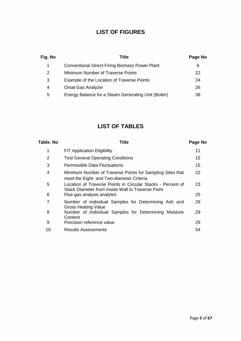
LIST OF FIGURES
Fig. No Title Page No
1 Conventional Direct-Firing Biomass Power Plant 9
2 Minimum Number of Traverse Points 22
3 Example of the Location of Traverse Points 24
4 Orsat Gas Analyzer 26
5 Energy Balance for a Steam Generating Unit (Boiler) 38
LIST OF TABLES
Table. No Title Page No
1 FiT Application Eligibility 11
2 Test General Operating Conditions 15
3 Permissible Data Fluctuations 15
4 Minimum Number of Traverse Points for Sampling Sites that
meet the Eight- and Two-diameter Criteria
22
5 Location of Traverse Points in Circular Stacks - Percent of Stack Diameter from Inside Wall to Traverse Point
23
6 Flue gas analysis analytes 25
7 Number of Individual Samples for Determining Ash and Gross Heating Value
29
8 Number of Individual Samples for Determining Moisture Content
29
9 Precision reference value 29
10 Results Assessments 54
Page 6 of 67
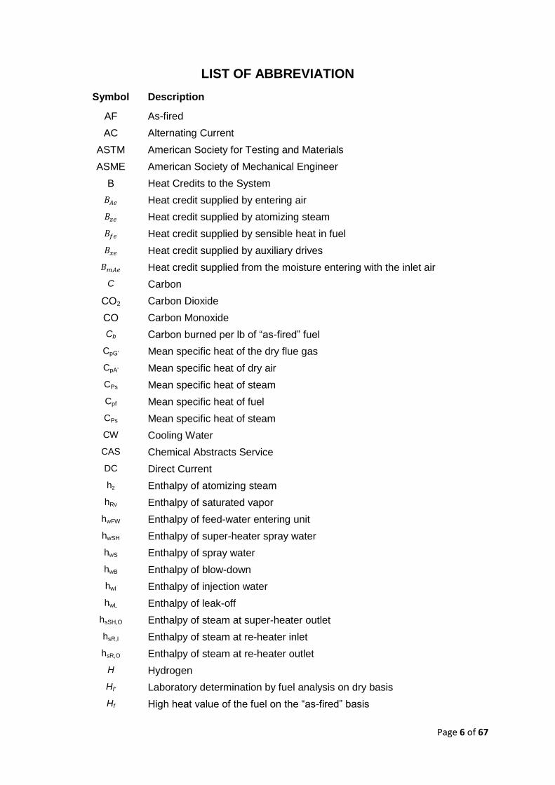
LIST OF ABBREVIATION
Symbol Description
AF As-fired
AC Alternating Current
ASTM American Society for Testing and Materials
ASME American Society of Mechanical Engineer
B Heat Credits to the System
Heat credit supplied by entering air
Heat credit supplied by atomizing steam
Heat credit supplied by sensible heat in fuel
Heat credit supplied by auxiliary drives
Heat credit supplied from the moisture entering with the inlet air
C Carbon
CO2 Carbon Dioxide
CO Carbon Monoxide
Cb Carbon burned per lb of “as-fired” fuel
CpG’ Mean specific heat of the dry flue gas
CpA’ Mean specific heat of dry air
CPs Mean specific heat of steam
Cpf Mean specific heat of fuel
CPs Mean specific heat of steam
CW Cooling Water
CAS Chemical Abstracts Service
DC Direct Current
hz Enthalpy of atomizing steam
hRv Enthalpy of saturated vapor
hwFW Enthalpy of feed-water entering unit
hwSH Enthalpy of super-heater spray water
hwS Enthalpy of spray water
hwB Enthalpy of blow-down
hwI Enthalpy of injection water
hwL Enthalpy of leak-off
hsSH,O Enthalpy of steam at super-heater outlet
hsR,I Enthalpy of steam at re-heater inlet
hsR,O Enthalpy of steam at re-heater outlet
H Hydrogen
Hf’ Laboratory determination by fuel analysis on dry basis
Hf High heat value of the fuel on the “as-fired” basis
Page 7 of 67
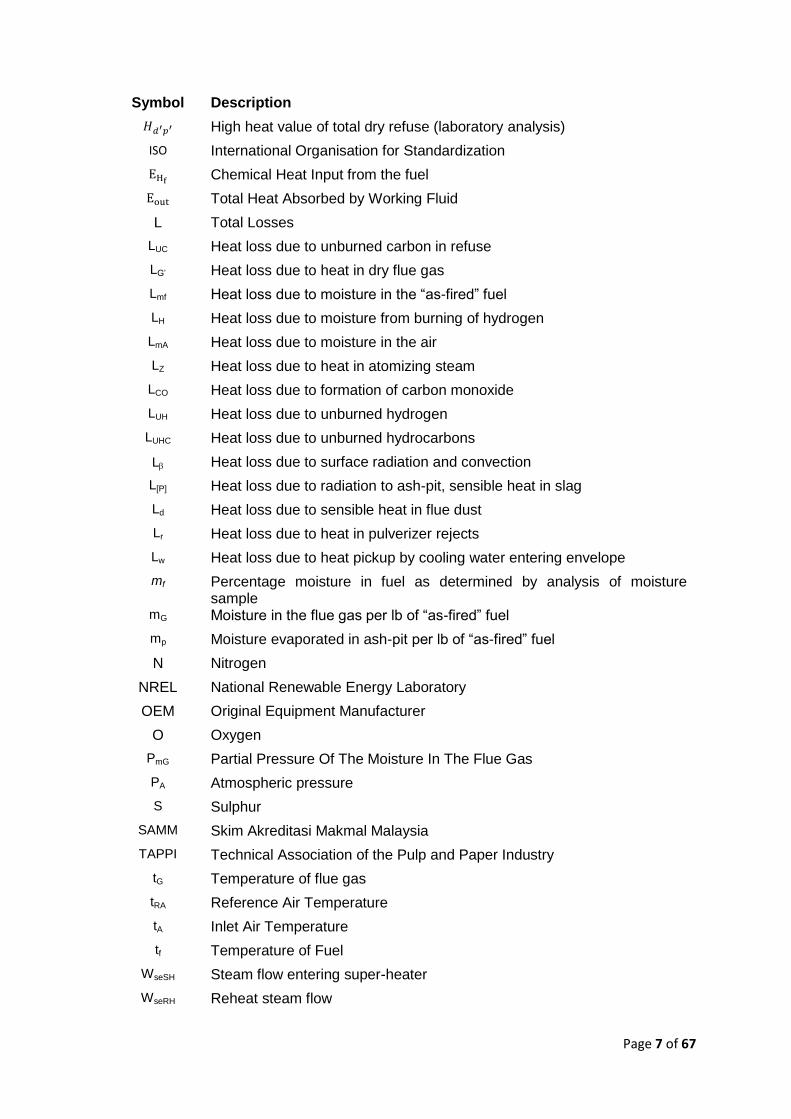
Symbol Description
High heat value of total dry refuse (laboratory analysis)
ISO International Organisation for Standardization
Chemical Heat Input from the fuel
Total Heat Absorbed by Working Fluid
L Total Losses
LUC Heat loss due to unburned carbon in refuse
LG’ Heat loss due to heat in dry flue gas
Lmf Heat loss due to moisture in the “as-fired” fuel
LH Heat loss due to moisture from burning of hydrogen
LmA Heat loss due to moisture in the air
LZ Heat loss due to heat in atomizing steam
LCO Heat loss due to formation of carbon monoxide
LUH Heat loss due to unburned hydrogen
LUHC Heat loss due to unburned hydrocarbons
L Heat loss due to surface radiation and convection
L[P] Heat loss due to radiation to ash-pit, sensible heat in slag
Ld Heat loss due to sensible heat in flue dust
Lr Heat loss due to heat in pulverizer rejects
Lw Heat loss due to heat pickup by cooling water entering envelope
mf Percentage moisture in fuel as determined by analysis of moisture sample
mG Moisture in the flue gas per lb of “as-fired” fuel
mp Moisture evaporated in ash-pit per lb of “as-fired” fuel
N Nitrogen
NREL National Renewable Energy Laboratory
OEM Original Equipment Manufacturer
O Oxygen
PmG Partial Pressure Of The Moisture In The Flue Gas
PA Atmospheric pressure
S Sulphur
SAMM Skim Akreditasi Makmal Malaysia
TAPPI Technical Association of the Pulp and Paper Industry
tG Temperature of flue gas
tRA Reference Air Temperature
tA Inlet Air Temperature
tf Temperature of Fuel
WseSH Steam flow entering super-heater
WseRH Reheat steam flow

Page 8 of 67
Symbol Description
WweSH Super-heater spray water flow
WweRH Reheat spray water flow
Wfe Rate of fuel firing (as-fired)
Wz Atomizing steam per lb of “as-fired” fuel
Dry refuse per lb of “as-fired” fuel
WG’ Dry gas per lb “as-fired” fuel burned
Measured fuel rate
Wt Whole tonne
Efficiency
VM Volatile Matter
Page 9 of 67
PART 1 INTRODUCTION
The Feed in Tariff (FiT) is Malaysia’s financial mechanism under the Renewable Policy and
Action Plan to catalyse generation of Renewable Energy (RE), up to 30 MW in size. The
mechanism allows electricity produced from RE resources to be sold to power utilities at a
fixed premium price for a specific duration to enable financial viability of RE plant
development.
FiT rates had been introduced through RE Act in 2011 to promote RE technology in
Malaysia. One of the RE technology which qualifies for FiT is biomass - an abundantly
available waste resources from the palm oil industry.
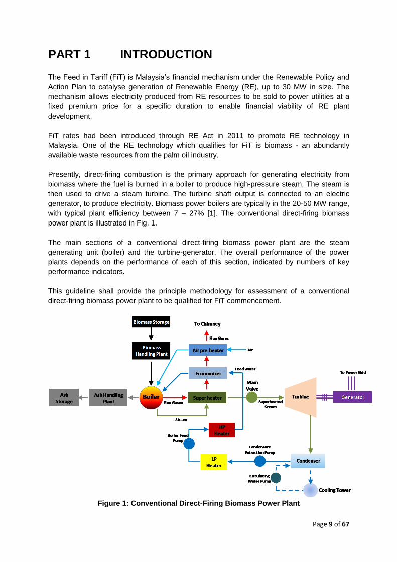
Presently, direct-firing combustion is the primary approach for generating electricity from
biomass where the fuel is burned in a boiler to produce high-pressure steam. The steam is
then used to drive a steam turbine. The turbine shaft output is connected to an electric
generator, to produce electricity. Biomass power boilers are typically in the 20-50 MW range,
with typical plant efficiency between 7 – 27% [1]. The conventional direct-firing biomass
power plant is illustrated in Fig. 1.
The main sections of a conventional direct-firing biomass power plant are the steam
generating unit (boiler) and the turbine-generator. The overall performance of the power
plants depends on the performance of each of this section, indicated by numbers of key
performance indicators.
This guideline shall provide the principle methodology for assessment of a conventional
direct-firing biomass power plant to be qualified for FiT commencement.
Figure 1: Conventional Direct-Firing Biomass Power Plant
Page 10 of 67
PART 2 PLANT PERFORMANCE ASSESSMENT
According to Guidelines and Determinations of the Sustainable Energy Development
Authority Malaysia (SEDA Malaysia) (rev Feb 2013), Acceptance Tests and Reliability Test
must be carried out in respect of all renewable energy installations. The Subparagraph
15(1)(a)(i) of the Technical and Operational Requirements Rules requires the submission by
the Feed-in Approval Holder (FiAH) to the distribution licensee and the Authority of a
certificate from a qualified person stating that the renewable energy installation and
interconnection facilities have been designed, constructed, installed and tested in
accordance with prudent utility practices. In addition, according to Subparagraph 8(a) of
Third Schedule to the Technical and Operational Requirements Rules requires the
submission by the FiAH to the distribution licensee and the Authority of a certificate from a
qualified person stating that the renewable energy installation has successfully completed a
Reliability Run.
2.1. Performance Assessments
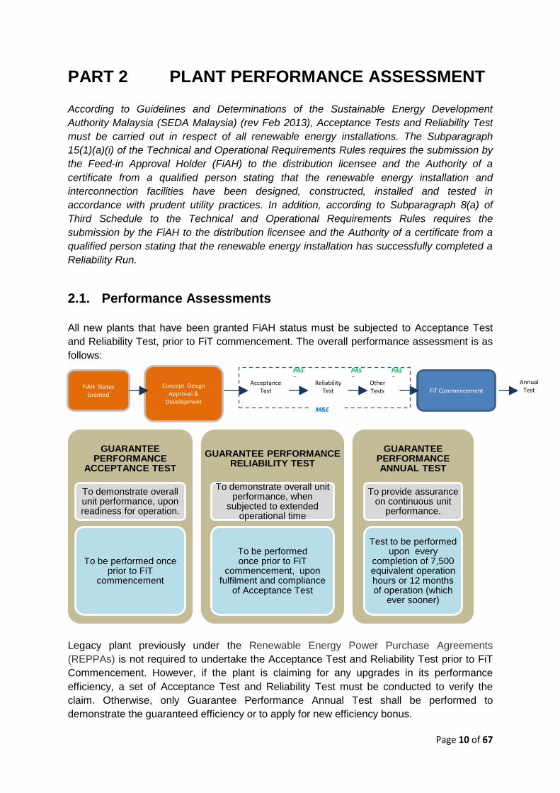
All new plants that have been granted FiAH status must be subjected to Acceptance Test
and Reliability Test, prior to FiT commencement. The overall performance assessment is as
follows:
Legacy plant previously under the Renewable Energy Power Purchase Agreements
(REPPAs) is not required to undertake the Acceptance Test and Reliability Test prior to FiT
Commencement. However, if the plant is claiming for any upgrades in its performance
efficiency, a set of Acceptance Test and Reliability Test must be conducted to verify the
claim. Otherwise, only Guarantee Performance Annual Test shall be performed to
demonstrate the guaranteed efficiency or to apply for new efficiency bonus.
GUARANTEE PERFORMANCE
ACCEPTANCE TEST
To demonstrate overall unit performance, upon readiness for operation.
To be performed once prior to FiT
commencement
GUARANTEE PERFORMANCE RELIABILITY TEST
To demonstrate overall unit performance, when
subjected to extended operational time
To be performed once prior to FiT
commencement, upon fulfilment and compliance
of Acceptance Test
GUARANTEE PERFORMANCE ANNUAL TEST
To provide assurance on continuous unit
performance.
Test to be performed upon every
completion of 7,500 equivalent operation hours or 12 months of operation (which
ever sooner)
FiAH Status Granted
Acceptance Test
Reliability Test FiT Commencement
Annual Test
PASS
PASS
Concept Design Approval &
Development
Other Tests
PASS
M&E
Page 11 of 67
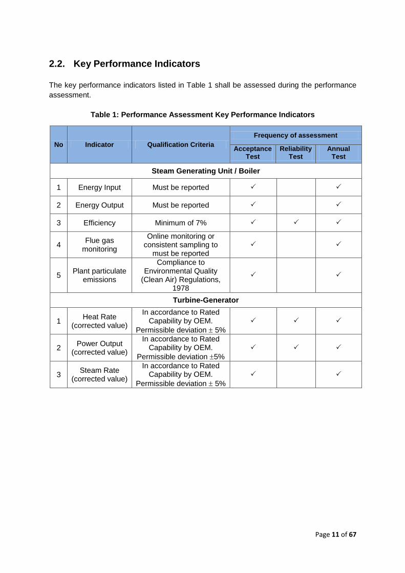
2.2. Key Performance Indicators
The key performance indicators listed in Table 1 shall be assessed during the performance
assessment.
Table 1: Performance Assessment Key Performance Indicators
No Indicator Qualification Criteria
Frequency of assessment
Acceptance Test
Reliability Test
Annual Test
Steam Generating Unit / Boiler
1 Energy Input Must be reported
2 Energy Output Must be reported
3 Efficiency Minimum of 7%
4 Flue gas
monitoring
Online monitoring or consistent sampling to
must be reported
5 Plant particulate
emissions
Compliance to Environmental Quality
(Clean Air) Regulations, 1978
Turbine-Generator
1 Heat Rate
(corrected value)
In accordance to Rated Capability by OEM.
Permissible deviation 5%
2 Power Output
(corrected value)
In accordance to Rated Capability by OEM.
Permissible deviation 5%
3 Steam Rate
(corrected value)
In accordance to Rated Capability by OEM.
Permissible deviation 5%
Page 12 of 67
PART 3 PERFORMANCE ASSESSMENT
GUIDELINE
3.1. Scope Of Assessment
3.1.1. Steam Generating Unit/ Boiler
Performance test to be carry out with reference to ASME Performance Test Code (PTC)
4.1 for the Steam Generating Unit/ Boiler and its supplementary test codes. The
parameters to be assessed are:
a. Energy Input
b. Energy Output
c. Boiler Efficiency (Guarantee Parameters)
d. Flue gas and plant emission
3.1.2. Turbine-Generator
Performance test to be carried out with reference to ASME PTC 6 for Steam Turbines
and its supplementary test codes. The Guarantee Parameters to be evaluated are:
a. Corrected Power (kW) (Guarantee Parameters)
b. Corrected Heat Rate (kJ/kWh) (Guarantee Parameters)
c. Steam Rate
3.2. Test Requirements
3.2.1. The rated capability
The rated capability of the unit must be specified prior to testing. The followings are
recommended rated capability parameters, which shall be provided by the OEM:
a. Boiler efficiency
b. Turbine-generator heat rate – heat consumption per unit output per hour (kJ/kWhr)
c. Turbine-generator power output– useful energy per unit of time delivered by turbine-
generator unit after reduction of parasitic load.
3.2.2. Minimum test runs and test durations
a. For Acceptance Test and Annual Test, the minimum test runs are for:
50% TMCR (Turbine Maximum Continuous Rating)
75% TMCR
100% TMCR
Each test run shall be conducted twice (two sets for each run).
Each set of test run shall be conducted for minimum of 4 hours
b. For Reliability Test
Test run shall be performed once at 100% TMCR
Test shall be conducted for a minimum of 300 hours duration (approximately for
14 days, 24 hrs operation, 90% uptime)
3.2.3. Frequency of data recording/ measurements
Page 13 of 67
a. All readings shall be taken as often as necessary to minimize error.
b. It is recommended that automatic data recording system to be used and data
recorded at no more than 60-seconds intervals.
c. In the absence of automatic data loggers, the following frequency of readings shall
be observed:
Flow measurements : 5 minutes
Pressure measurements : 10 minutes
Temperature measurements : 10 minutes
Storage vessels water level measurements : 10 minutes
Electrical power measurements : 5 minutes
Flue gas sampling : 15 minutes
Fuel sampling : 15 minutes
Ash sample analysis : 15 minutes
0
3.3. Test Preparation
All FiAH shall first ensure the provision and ports for measurements are incorporated in
the plant design and development stage to enable data collection during performance
verification and annual certification. Prior to test commencement, a review of the
required documents inclusive of the Process and Instrumentation Diagrams (P & IDs) for
the plant and system is required. The followings pre-test checklist shall also be
performed:
a. Complete list of all equipment to be subjected to the test and its respective
performance guarantee values at installation. The historical data on present
operating conditions of equipment and operating hours logged must be established.
b. Establish specific test procedures, with reference to this guideline. Procedures shall
explicitly describe any exceptions.
c. Prepare a complete test datasheet containing parameter to be measured, methods of
measurement and instruments to be used shall be established with reference to this
guideline
d. Establish performance analysis procedure, with reference to this guideline
e. Check for calibration record of all instruments to be used for measurement. All
equipment shall be calibrated prior to testing. . The valid calibration certificate, not
more than six months old, conforming to internationally recognized calibration
standards, for all the instruments installed in the field and used as portable along with
the traceability should be available for verification prior to test.
f. Check that typical test data logged automatically in all data-logging system
g. Establish specific time duration for each test and minimum number of tests.
h. Check all operating parameters under which the performance needs to be evaluated,
for each equipment in the system.
i. Ensure all heat transfer surfaces to be clean and the entire unit shall be checked for
leakage
j. Prior to the test, it shall be ensured that the intended fuel is being used as the as-
fired fuel
Page 14 of 67
k. Prepare list of personnel assigned for data measurement/recording throughout the
test
l. It is also essential to obtain the performance, losses and correction curves data,
generally supplied by the respective Original Equipment Manufacturer (OEM)
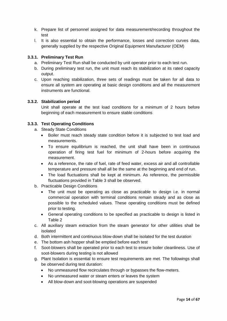
3.3.1. Preliminary Test Run
a. Preliminary Test Run shall be conducted by unit operator prior to each test run.
b. During preliminary test run, the unit must reach its stabilization at its rated capacity
output.
c. Upon reaching stabilization, three sets of readings must be taken for all data to
ensure all system are operating at basic design conditions and all the measurement
instruments are functional.
3.3.2. Stabilization period
Unit shall operate at the test load conditions for a minimum of 2 hours before
beginning of each measurement to ensure stable conditions
3.3.3. Test Operating Conditions
a. Steady State Conditions
Boiler must reach steady state condition before it is subjected to test load and
measurements.
To ensure equilibrium is reached, the unit shall have been in continuous
operation of firing test fuel for minimum of 2-hours before acquiring the
measurement.
As a reference, the rate of fuel, rate of feed water, excess air and all controllable
temperature and pressure shall all be the same at the beginning and end of run.
The load fluctuations shall be kept at minimum. As reference, the permissible
fluctuations provided in Table 3 shall be observed.
b. Practicable Design Conditions
The unit must be operating as close as practicable to design i.e. in normal
commercial operation with terminal conditions remain steady and as close as
possible to the scheduled values. These operating conditions must be defined
prior to testing.
General operating conditions to be specified as practicable to design is listed in
Table 2
c. All auxiliary steam extraction from the steam generator for other utilities shall be
isolated
d. Both intermittent and continuous blow-down shall be isolated for the test duration
e. The bottom ash hopper shall be emptied before each test
f. Soot-blowers shall be operated prior to each test to ensure boiler cleanliness. Use of
soot-blowers during testing is not allowed
g. Plant Isolation is essential to ensure test requirements are met. The followings shall
be observed during test duration:
No unmeasured flow recirculates through or bypasses the flow-meters.
No unmeasured water or steam enters or leaves the system
All blow-down and soot-blowing operations are suspended
Page 15 of 67
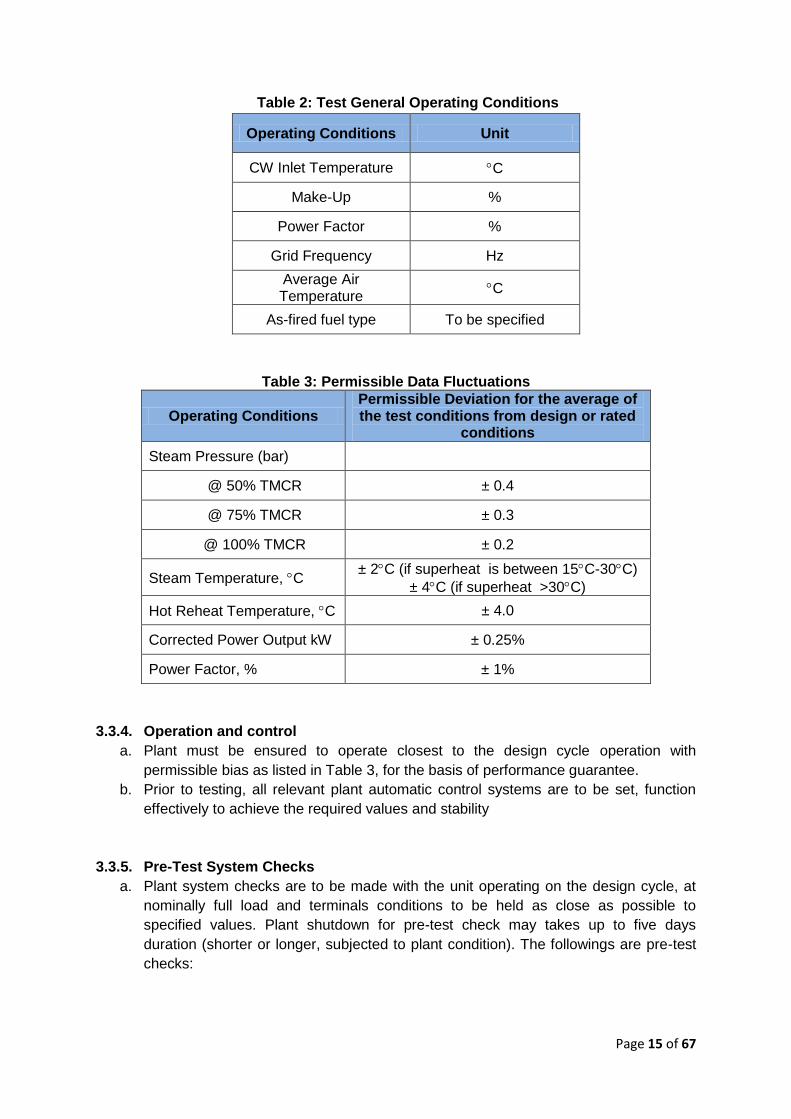
Table 2: Test General Operating Conditions
Operating Conditions Unit
CW Inlet Temperature C
Make-Up %
Power Factor %
Grid Frequency Hz
Average Air Temperature
C
As-fired fuel type To be specified
Table 3: Permissible Data Fluctuations
Operating Conditions Permissible Deviation for the average of the test conditions from design or rated
conditions
Steam Pressure (bar)
@ 50% TMCR ± 0.4
@ 75% TMCR ± 0.3
@ 100% TMCR ± 0.2
Steam Temperature, C ± 2C (if superheat is between 15C-30C)
± 4C (if superheat >30C)
Hot Reheat Temperature, C ± 4.0
Corrected Power Output kW ± 0.25%
Power Factor, % ± 1%
3.3.4. Operation and control
a. Plant must be ensured to operate closest to the design cycle operation with
permissible bias as listed in Table 3, for the basis of performance guarantee.
b. Prior to testing, all relevant plant automatic control systems are to be set, function
effectively to achieve the required values and stability
3.3.5. Pre-Test System Checks
a. Plant system checks are to be made with the unit operating on the design cycle, at
nominally full load and terminals conditions to be held as close as possible to
specified values. Plant shutdown for pre-test check may takes up to five days
duration (shorter or longer, subjected to plant condition). The followings are pre-test
checks:
Page 16 of 67
Check for turbine cycle operating conditions at nominal full load. This includes
values and stability of steam inlet pressure, temperature, and their respective
patterns through the cycle.
Inspection of all valves for leakage and passing
Condenser air leakage test
Air heater leakage test
Preliminary checks of boiler’s combustion circuit and steam circuit for test set-up
Firing conditions optimization
Excess air, nozzle positions and air distribution
Soot-blower operation
b. All work done during plant system checks must be included in the test report
3.3.6. Test Manning Plan
a. Distribution Licensee, SEDA Malaysia or its appointed representative shall be
presented to witness the conduct of performance assessment. Notification shall be
given to the respective authorised personnel at minimum of 14 days prior to
performance assessment commencement.
b. The followings personnel shall be presented during test:
Overall test controller
Boiler test engineer
Boiler operation engineer
Turbine test engineer
Turbine operations engineer
Test electrical engineer
Test instrumentations technician
Fuel and ash sampling teams
Observers for manual readings
Other personnel as needed
c. List of presented personnel must be included in the test report.
Page 17 of 67
PART 4 TEST INSTRUMENTATIONS AND DATA
ACQUISITION
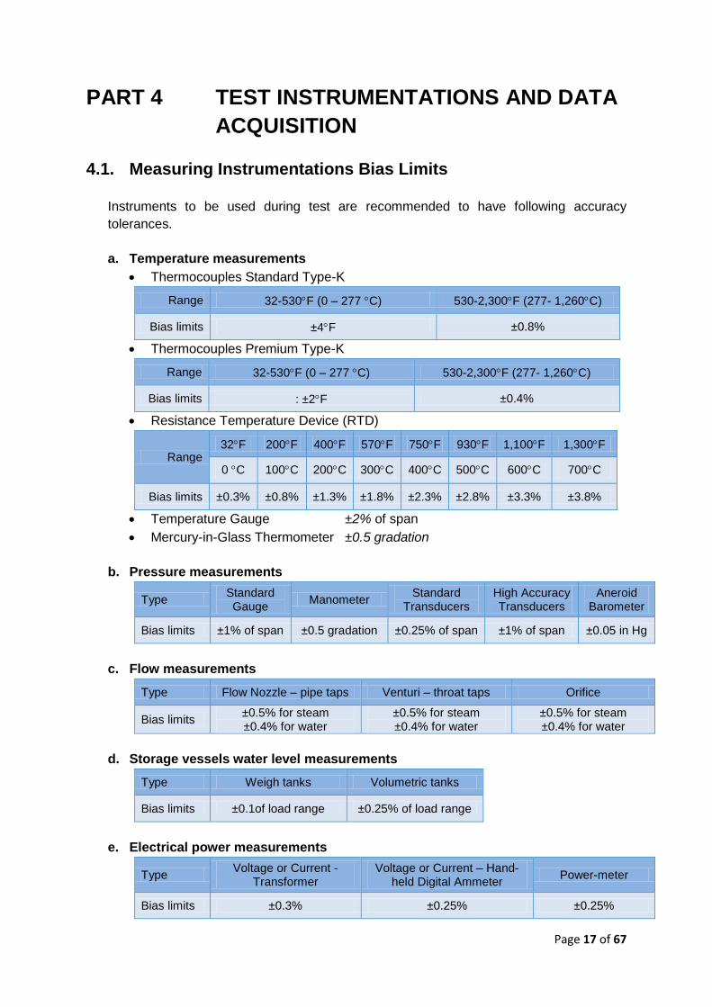
4.1. Measuring Instrumentations Bias Limits
Instruments to be used during test are recommended to have following accuracy
tolerances.
a. Temperature measurements
Thermocouples Standard Type-K
Range 32-530F (0 – 277 C) 530-2,300F (277- 1,260C)
Bias limits ±4F ±0.8%
Thermocouples Premium Type-K
Range 32-530F (0 – 277 C) 530-2,300F (277- 1,260C)
Bias limits : ±2F ±0.4%
Resistance Temperature Device (RTD)
Range 32F 200F 400F 570F 750F 930F 1,100F 1,300F
0 C 100C 200C 300C 400C 500C 600C 700C
Bias limits ±0.3% ±0.8% ±1.3% ±1.8% ±2.3% ±2.8% ±3.3% ±3.8%
Temperature Gauge ±2% of span
Mercury-in-Glass Thermometer ±0.5 gradation
b. Pressure measurements
Type Standard Gauge
Manometer Standard
Transducers High Accuracy Transducers
Aneroid Barometer
Bias limits ±1% of span ±0.5 gradation ±0.25% of span ±1% of span ±0.05 in Hg
c. Flow measurements 0
Type Flow Nozzle – pipe taps Venturi – throat taps Orifice
Bias limits ±0.5% for steam ±0.4% for water
±0.5% for steam ±0.4% for water
±0.5% for steam ±0.4% for water
d. Storage vessels water level measurements
Type Weigh tanks Volumetric tanks
Bias limits ±0.1of load range ±0.25% of load range
e. Electrical power measurements
Type Voltage or Current -
Transformer Voltage or Current – Hand-
held Digital Ammeter Power-meter
Bias limits ±0.3% ±0.25% ±0.25%
Page 18 of 67
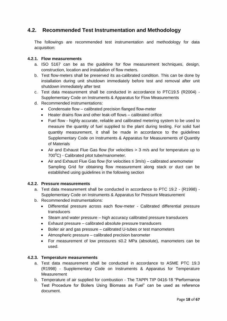
4.2. Recommended Test Instrumentation and Methodology
The followings are recommended test instrumentation and methodology for data
acquisition:
4.2.1. Flow measurements
a. ISO 5167 can be as the guideline for flow measurement techniques, design,
construction, location and installation of flow meters.
b. Test flow-meters shall be preserved its as-calibrated condition. This can be done by
installation during unit shutdown immediately before test and removal after unit
shutdown immediately after test
c. Test data measurement shall be conducted in accordance to PTC19.5 (R2004) -
Supplementary Code on Instruments & Apparatus for Flow Measurements
d. Recommended instrumentations:
Condensate flow – calibrated precision flanged flow-meter
Heater drains flow and other leak-off flows – calibrated orifice
Fuel flow - highly accurate, reliable and calibrated metering system to be used to
measure the quantity of fuel supplied to the plant during testing. For solid fuel
quantity measurement, it shall be made in accordance to the guidelines
Supplementary Code on Instruments & Apparatus for Measurements of Quantity
of Materials
Air and Exhaust Flue Gas flow (for velocities > 3 m/s and for temperature up to
7000C) - Calibrated pitot tube/manometer.
Air and Exhaust Flue Gas flow (for velocities ≤ 3m/s) – calibrated anemometer
Sampling Grid for obtaining flow measurement along stack or duct can be
established using guidelines in the following section
4.2.2. Pressure measurements
a. Test data measurement shall be conducted in accordance to PTC 19.2 - (R1998) -
Supplementary Code on Instruments & Apparatus for Pressure Measurement
b. Recommended instrumentations:
Differential pressure across each flow-meter - Calibrated differential pressure
transducers
Steam and water pressure – high accuracy calibrated pressure transducers
Exhaust pressure – calibrated absolute pressure transducers
Boiler air and gas pressure – calibrated U-tubes or test manometers
Atmospheric pressure – calibrated precision barometer
For measurement of low pressures ≤0.2 MPa (absolute), manometers can be
used.
4.2.3. Temperature measurements
a. Test data measurement shall be conducted in accordance to ASME PTC 19.3
(R1998) - Supplementary Code on Instruments & Apparatus for Temperature
Measurement
b. Temperature of air supplied for combustion - The TAPPI TIP 0416-18 “Performance
Test Procedure for Boilers Using Biomass as Fuel” can be used as reference
document.
Page 19 of 67
c. Recommended instrumentations:
Condensate, feed and steam temperatures - Calibrated platinum resistance
temperature detectors (RTDs).
Air heater inlet and outlet temperature – Grid of K-type thermocouples. Grid shall
be installed along the gas sampling grid.
4.2.4. Storage vessels water level measurements
a. Design, construction and operation of measuring equipment shall be made in
accordance to the guidelines Supplementary Code on Instruments & Apparatus for
Measurements of Quantity of Materials
b. Recommended instrumentations:
Steam or condensate entering or leaving the cycle - Weigh tanks
Water volume - Volumetric tanks
Control room panel (where applicable)
4.2.5. Electrical power measurements
a. Calibrated power analyser to be connected to the installed transformer to measure
total output at the high voltage terminals of the main transformer
b. In case of existence of any external tap between the generator and the point of
measurement, supplementary metering of equivalent accuracy may be provided to
determine the total generator output.
c. The ASME PTC 19.6 “Electrical Measurements in Power Circuit” or equivalent
standard test code shall be use for detailed instructions for measurement of electrical
quantities
d. Recommended instrumentations:
AC Generators – single-phase watt-hour meter to be used in each phase to
determine power output
Power factor, current and voltage - Ammeter and voltmeter
DC Generators – DC-ammeters and DC-voltmeters
4.2.6. Ash sample analysis
a. Fly ash samples to be collected from ash abatement system. Samples shall be
collected continuously, weighted, packaged, sealed and properly labelled at each
test.
b. Siftings ash / front bottom ash shall be obtained by combining 2kg samples from the
discharge of the scraper conveyors at 15-minutes intervals. Samples shall be
collected continuously, weighted, packaged, sealed and properly labelled at each
test.
c. The followings procedures are recommended for ash sample analysis:
ASTM D5373 - 08 Standard Test Methods for Instrumental Determination of
Carbon, Hydrogen, and Nitrogen in Laboratory Samples of Coal (Replacing
ASTM D3178-89(2002) Standard Test Methods for Carbon and Hydrogen in the
Analysis Sample of Coal and Coke (Withdrawn 2007))
ASTM D6316 - 09b Standard Test Method for Determination of Total,
Combustible and Carbonate Carbon in Solid Residues from Coal and Coke
(Replacing ASTM D1756-02(2007) Standard Test Method for Determination as
Carbon Dioxide of Carbonate Carbon in Coal (Withdrawn 2013))

Page 20 of 67
Content of combustible in refuse stream (flue gas, siftings and front bottom ash)
shall be calculated in accordance with TAPPI TIP 0416-18 “Performance Test
Procedure for Boilers Using Biomass as Fuel” reference document.
4.2.7. Measurement of Time
The measurement of time of test durations and other observations can be
determined by observations of synchronized stop watches by the individual
observers. Watches and clocks can be synchronized at the start of the test with the
plant data and instruments.
Page 21 of 67
4.3. Air Flow, Exhaust Flue Gas Flow And Temperature Sampling
Grid
The following methodology provides guideline for establishing sampling grid at the stack/
duct.
a. Measurement Site
Select a site in a straight section of stack or duct located at least eight stack or
duct diameters downstream and two stack or duct diameters upstream of any
flow disturbance such as a bend, expansion, contraction, visible flame, junction,
or stack exit.
In the case of rectangular stacks or ducts, an equivalent diameter (De) shall be
used in determining the downstream and upstream distances.
Where
L = stack length
W = stack width
In circular stacks or ducts, at least two sampling ports with a 90° separation are
required. For particulate traverses, one diameter should be in the plane of an
upstream flow disturbance.
For rectangular flow areas, ports are located on the most accessible face of the
duct. The number of ports will be determined by the total number of traverse
points.
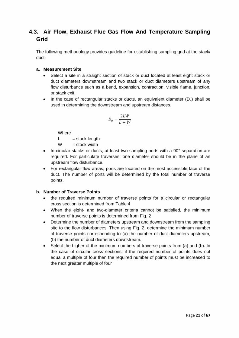
b. Number of Traverse Points
the required minimum number of traverse points for a circular or rectangular
cross section is determined from Table 4
When the eight- and two-diameter criteria cannot be satisfied, the minimum
number of traverse points is determined from Fig. 2
Determine the number of diameters upstream and downstream from the sampling
site to the flow disturbances. Then using Fig. 2, determine the minimum number
of traverse points corresponding to (a) the number of duct diameters upstream,
(b) the number of duct diameters downstream.
Select the higher of the minimum numbers of traverse points from (a) and (b). In
the case of circular cross sections, if the required number of points does not
equal a multiple of four then the required number of points must be increased to
the next greater multiple of four
Page 22 of 67
Table 4: Minimum Number of Traverse Points for Sampling Sites that meet the
Eight- and Two-diameter Criteria
Stack or Duct Diameter
(m)
Required Minimum Number of Traverse Points
Circular Duct Rectangular Duct
> 0.61 12 12
0.30 to 0.61 8 9
Figure 2: Minimum Number of Traverse Points
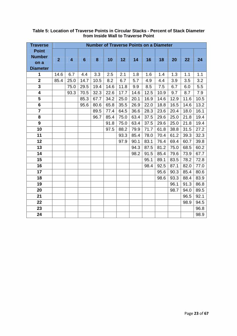
c. Location of Traverse Points
For stacks or ducts with a circular cross section, locate the traverse points
according to Table 5. These points are located at the centroid of equal areas of
the cross section
The minimum distance between the stack wall and a traverse point shall be 2.5
cm (1.0 in) for stacks with diameters greater than 0.61 m (24 in) and 1.3 cm (0.5
in) for stacks with diameters less than 0.61 m (24 in)
For rectangular cross sections, the area is divided into as many equal rectangular
sections as there are sampling points
Locate the traverse points at the centroid of these rectangular sections.
The cross-sectional layout of a rectangular duct shall be chosen such that the
ratio of the length to the width is between 1.0 and 2.0
Page 23 of 67
Table 5: Location of Traverse Points in Circular Stacks - Percent of Stack Diameter from Inside Wall to Traverse Point
Traverse
Point
Number
on a
Diameter
Number of Traverse Points on a Diameter
2 4 6 8 10 12 14 16 18 20 22 24
1 14.6 6.7 4.4 3.3 2.5 2.1 1.8 1.6 1.4 1.3 1.1 1.1
2 85.4 25.0 14.7 10.5 8.2 6.7 5.7 4.9 4.4 3.9 3.5 3.2
3
75.0 29.5 19.4 14.6 11.8 9.9 8.5 7.5 6.7 6.0 5.5
4
93.3 70.5 32.3 22.6 17.7 14.6 12.5 10.9 9.7 8.7 7.9
5
85.3 67.7 34.2 25.0 20.1 16.9 14.6 12.9 11.6 10.5
6
95.6 80.6 65.8 35.5 26.9 22.0 18.8 16.5 14.6 13.2
7
89.5 77.4 64.5 36.6 28.3 23.6 20.4 18.0 16.1
8
96.7 85.4 75.0 63.4 37.5 29.6 25.0 21.8 19.4
9
91.8 75.0 63.4 37.5 29.6 25.0 21.8 19.4
10
97.5 88.2 79.9 71.7 61.8 38.8 31.5 27.2
11
93.3 85.4 78.0 70.4 61.2 39.3 32.3
12
97.9 90.1 83.1 76.4 69.4 60.7 39.8
13
94.3 87.5 81.2 75.0 68.5 60.2
14
98.2 91.5 85.4 79.6 73.9 67.7
15
95.1 89.1 83.5 78.2 72.8
16
98.4 92.5 87.1 82.0 77.0
17
95.6 90.3 85.4 80.6
18
98.6 93.3 88.4 83.9
19
96.1 91.3 86.8
20
98.7 94.0 89.5
21
96.5 92.1
22
98.9 94.5
23
96.8
24
98.9
Page 24 of 67
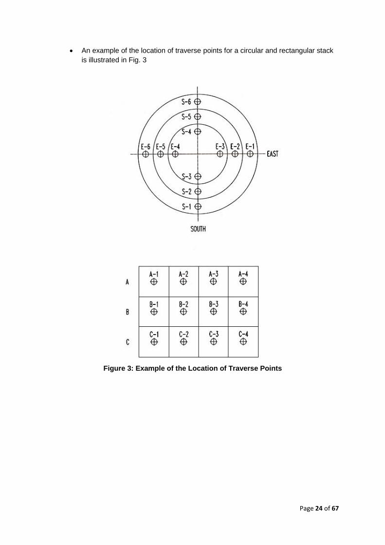
An example of the location of traverse points for a circular and rectangular stack
is illustrated in Fig. 3
Figure 3: Example of the Location of Traverse Points
Page 25 of 67
4.4. Flue Gas Analysis
4.4.1. General guideline for flue gas analysis:
a. Flue gas samples entering and leaving air heaters to be continuously collected point
test sampling probes within the respective gas ducts.
b. Flue gas sampling must be taken at the same point used for flue gas temperature
measurement, using similar guideline for sampling points
c. Calibrated Orsat flue gas analyser shall be used to analyse the samples for oxygen,
carbon dioxide and carbon monoxide.
d. Flue gas compositions: Sampling and analysis of CO2, O2 and CO in accordance with
ASME PTC 19.10 Supplementary Code on Instruments & Apparatus - Flue and
Exhaust Gas Analyses and reference methodology specified in this document
4.4.2. Analytes
Flue gas analysis shall be observed for the analytes in Table 6
4.4.3. Apparatus
a. Probe
Stainless steel or borosilicate glass tubing equipped with an in-stack or out-stack filter
to remove particulate matter (a plug of glass wool is satisfactory for this purpose).
Any other material inert to O2, CO2, CO, and N2 and resistant to temperature at
sampling conditions may be used for the probe; examples of such material are
aluminum, copper, quartz glass and Teflon.
b. Pump
A one-way squeeze bulb, or equivalent, to transport the gas sample to the analyser.
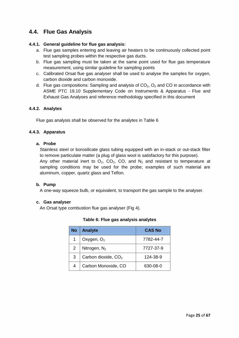
c. Gas analyser
An Orsat type combustion flue gas analyser (Fig 4).
Table 6: Flue gas analysis analytes
No Analyte CAS No
1 Oxygen, O2 7782-44-7
2 Nitrogen, N2 7727-37-9
3 Carbon dioxide, CO2 124-38-9
4 Carbon Monoxide, CO 630-08-0
Page 26 of 67
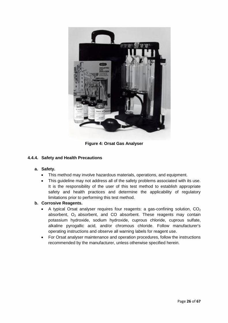
Figure 4: Orsat Gas Analyser
4.4.4. Safety and Health Precautions
a. Safety.
This method may involve hazardous materials, operations, and equipment.
This guideline may not address all of the safety problems associated with its use.
It is the responsibility of the user of this test method to establish appropriate
safety and health practices and determine the applicability of regulatory
limitations prior to performing this test method.
b. Corrosive Reagents.
A typical Orsat analyser requires four reagents: a gas-confining solution, CO2
absorbent, O2 absorbent, and CO absorbent. These reagents may contain
potassium hydroxide, sodium hydroxide, cuprous chloride, cuprous sulfate,
alkaline pyrogallic acid, and/or chromous chloride. Follow manufacturer's
operating instructions and observe all warning labels for reagent use.
For Orsat analyser maintenance and operation procedures, follow the instructions
recommended by the manufacturer, unless otherwise specified herein.
Page 27 of 67
4.4.5. Procedures and Analysis
a. Set up the gas sampling equipment, making sure all connections ahead of the
analyser are tight. It is recommended that the Orsat analyser be leak-checked
b. Place the probe in the stack, with the tip of the probe positioned at the sampling point
Purge the sampling line long enough to allow at least 5 exchanges.
c. Draw a sample into the analyser and immediately analyse it for percent CO2, O2 and
CO. Determine the percentage of the gas that is N2 by subtracting the sum of the
percentage of CO2, O2 and CO from 100%.
d. Repeat the sampling, analysis, and calculation procedures, until the dry molecular
weights of any three grab samples differ from their mean by no more than 0.3 g/g-
mole (0.3 lb/lb-mole).
e. Average these three molecular weights, and report the results to the nearest 0.1 g/g-
mole (lb/lb-mole).
f. After the analysis is completed, leaks check (mandatory) the Orsat analyser once
again. For the results of the analysis to be valid, the Orsat analyser must pass this
leak test before and after the analysis.
g. For results validation, calculate the fuel factor, Fo using the following equation:
Where:
%O2 = %O2 (adj) = %O2 - 0.5 %CO
%CO2 = %CO2 (adj) = %CO2 + %CO
%CO = Percent CO by volume (dry basis).
20.9 = Percent O2 by volume in ambient air.
Compare the calculated FO factor with the expected Fo values. The acceptable ranges
for the expected Fo is 1.003 -1.130.
Page 28 of 67
4.5. Fuel Sampling and Analysis
4.5.1. General guideline for sampling of biomass:
a. Frequency
Sample shall be taken at regular intervals during each performance test run
b. Point
Sample shall be collected as close to the boiler as possible such as at the conveyor
c. Sampling apparatus
Dimension of sampling apparatus and the size of the sample are suitable for the
maximum fuel size
d. Sample preparation
When sample has been taken, two laboratory samples are to be prepared – one
for moisture analysis, and another one for analysis of ash content, chemical and
physical properties
When sample has been taken for moisture analysis, it must be weighted as soon
as possible. For storage, it must be kept in a sealed, air-tight container and to be
stored at a temperature lower than where the samples are taken
e. No of individual samples
No of individual samples depends on the non-homogeneity of the fuel which varies
according to fuel type, particle size and the segregation rate.
f. The minimum size of an individual sample: Depends on the particle size of the fuel.
Minimum size of individual samples when at least 95% of the fuel is smaller than
100mm (4 inches) shall be 10 litres. In addition, the followings shall be noted:
When sampling from a stopped conveyor, the width of the belt at the sampling
point should be at least 2.5 times the maximum fuel size
When sampling from truck or pile, the minimum opening size of the sampling
device (scoop or probe) should be 2.5 times the maximum fuel size
g. Test report
Sampling test report shall describe the followings:
Sampling method
Design of sampling equipment
Sampling procedure
Number of individual samples
h. Sample labelling
Sampling container shall describe the followings:
Name and designation of sampler
Type of fuel
Test number, test date and time
Sample collection number, date, time
Total solids content
Page 29 of 67
4.5.2. Guidelines for Sampling from Conveyor Belt (fuel flow - stationary or in
motion)
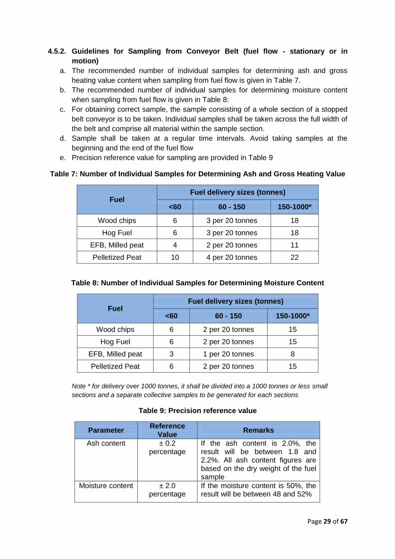
a. The recommended number of individual samples for determining ash and gross
heating value content when sampling from fuel flow is given in Table 7.
b. The recommended number of individual samples for determining moisture content
when sampling from fuel flow is given in Table 8:
c. For obtaining correct sample, the sample consisting of a whole section of a stopped
belt conveyor is to be taken. Individual samples shall be taken across the full width of
the belt and comprise all material within the sample section.
d. Sample shall be taken at a regular time intervals. Avoid taking samples at the
beginning and the end of the fuel flow
e. Precision reference value for sampling are provided in Table 9
Table 7: Number of Individual Samples for Determining Ash and Gross Heating Value
Fuel Fuel delivery sizes (tonnes)
<60 60 - 150 150-1000*
Wood chips 6 3 per 20 tonnes 18
Hog Fuel 6 3 per 20 tonnes 18
EFB, Milled peat 4 2 per 20 tonnes 11
Pelletized Peat 10 4 per 20 tonnes 22
Table 8: Number of Individual Samples for Determining Moisture Content
Fuel Fuel delivery sizes (tonnes)
<60 60 - 150 150-1000*
Wood chips 6 2 per 20 tonnes 15
Hog Fuel 6 2 per 20 tonnes 15
EFB, Milled peat 3 1 per 20 tonnes 8
Pelletized Peat 6 2 per 20 tonnes 15
Note * for delivery over 1000 tonnes, it shall be divided into a 1000 tonnes or less small
sections and a separate collective samples to be generated for each sections
Table 9: Precision reference value
Parameter Reference
Value Remarks
Ash content ± 0.2 percentage
If the ash content is 2.0%, the result will be between 1.8 and 2.2%. All ash content figures are based on the dry weight of the fuel sample
Moisture content ± 2.0 percentage
If the moisture content is 50%, the result will be between 48 and 52%
Page 30 of 67
4.5.3. Reference Procedure for Sample Preparations
Principally, the sample shall be dried, milled and sieved before submitted to further
compositional analysis. This procedure describes a reproducible way to convert a variety of
biomass samples into a uniform material suitable for compositional analysis. It is a guideline
for drying, size reduction, obtaining samples with a uniform particle size and representative
sampling of biomass samples prior to analysis for many other constituents. The procedures
is similar to ASTM E1757-01(2007), TAPPI Test Method T264 cm-97 and NREL/TP-510-
42620. This procedure is applicable for most types of biomass and biomass- derived solids
for compositional analysis. However, it is not applicable for the followings:
a. Materials that pass through a 20-mesh sieve.
b. Materials that cannot be dried by the described methods to a total solids content of
greater than 90% of the sample’s oven dried weight.
4.5.3.1. Safety and Health Considerations
This Procedure does not address all of the safety concerns associated with its use. It is the
responsibility of the user of this guideline to establish appropriate safety and health practices
and determine the applicability of regulatory limitations prior to use. However, the followings
safety and health considerations shall be observed during sampling:
a. Milling and sieving actions both produce large amounts of dust. This dust can be a
nuisance, hazard, or irritant. Use appropriate respiratory protection and eye
protection as needed.
b. If excessive amounts of dust are allowed to become airborne, a potential explosion
hazard is possible. Provide appropriate dust control measures as needed.
c. Follow all applicable laboratory chemical handling procedures.
4.5.3.2. Methods, Apparatus, Reagents And Materials
a. Method:
To obtain a dried biomass sample for further analysis, the solids content of the
sample is to be tested throughout this procedure. Solid content can be tested using
any of the following standards:
NREL/TP-510-42621 (2008) Laboratory Analytical Procedure (LAP) for
Determination of Total Solids in Biomass and Total Dissolved Solids in Liquid
Process Samples
TAPPI Method T412 om-02. 2002. "Moisture in Pulp, Paper and Paperboard."
Test methods of the Technical Association of the Pulp and Paper Industry 2002-
2003.
ASTM E1756 - 08 Standard Test Method for Determination of Total Solids in
Biomass

Page 31 of 67
b. Apparatus:
The followings are the required apparatus for sample preparations:
Large table or drying rack for air drying biomass (method A only).
Convection oven capable of maintaining 45 ±5ºC (method B only).
Freeze-Drier - System with vacuum chamber and pump capable of maintaining a
pressure of <1 torr and a cold finger in the chamber capable of maintaining a
temperature of -50°C (method C only).
Assorted trays
Containers as appropriate for the selected drying method.
Balance, sensitive to 0.1 g.
Standard laboratory knife mill with 2 mm screen. A Wiley Mill, size No. 4 with a 2-
mm screen, is suitable for samples >20 g, and the intermediate model Wiley Mill,
with 1-mm screen, is suitable for samples <20 g that will not be sieved.
Equivalent knife mills are acceptable.
Sieve Shaker that provides motion in both horizontal and vertical axes- for
optional sieving step
Sieve Set, No. 20 (850 μm), No. 80 (180 μm) stackable sieves with lid and bottom
pan. Sieves and bottom pan should be 8.9 cm (31/2 in.) in height. Sieves should
conform to ASTM Specification E 11.
Riffle Sampler with Pans –– A manual sample divider that splits the milled
biomass into two or more equivalent sub-samples. Riffle divisions should be
between 6.4 mm and 12.7 mm (1/4 to 1/2 in.) with at least twenty-four riffle
openings. The feed chute and riffles should have a slope of at least 60°.
Collection pans, one to pour the sample into the riffler, and two or more to collect
the sub–samples.
c. Reagents
This is applicable for lyophilization method only
Acetone (electronic grade)
Dry ice (ground).
4.5.3.3. Sample Drying Procedure
Dried biomass sample shall be prepared using one of these methods
4.5.3.3.1. Method A - Air-drying.
a. This method is suitable for the preparation of large quantities (>20 g) of field-
collected samples
b. Biomass samples must be prepared as pieces with overall dimensions less than 5cm
x 5cm x 0.6 cm.
c. The biomass material is then to be spread out on a suitable surface and allowed to
air-dry prior to any milling. Do not pile the material deeper than 15 cm.
d. Turn the material at least once per day to ensure even drying and inhibit microbial
growth in samples.
e. Check the solids content of the biomass sample using one of the methods described
above
f. The material is considered dried when the moisture content is less than 10% by
weight and the change in weight is less than 1% in 24 hours.
Page 32 of 67
4.5.3.3.2. Method B - Convection Oven Drying.
a. This drying method is suitable for small samples of biomass (<20 g) and when air-
drying is impossible. This method is recommended for
very wet biomass samples that are at risk for microbial growth during air-drying,
wet pre-treated biomass,
samples that would not be stable during prolonged exposure to ambient
conditions,
drying materials when ambient humidity does not allow the sample to air-dry to a
moisture content
b. Select a container suitable for oven drying the biomass sample and dry this container
at 45± 3°C for a minimum of 3 h.
c. Place the container in desiccators and allow the container to cool to room
temperature.
d. Weigh the container to the nearest 0.1 g and record this weight as W t.
e. Place the biomass material into the dried container to a maximum depth of 1 cm.
f. Weigh the container and biomass to the nearest 0.1 g and record this weight as W i.
g. Place the container and biomass in a drying oven maintaining the temperature at 45
± 3°C. Allow the material to dry for 24 to 48 h.
h. Remove the container and biomass from the drying oven, place in desiccators and
allow the sample to cool to room temperature.
i. Weigh the container and biomass to the nearest 0.1 g and record this weight as W f.
j. Return the sample to the drying oven, maintaining the temperature at 45 ± 3°. Keep
the sample in the drying oven at 45 ± 3°C for minimum of 4 hr.
k. Remove the container and biomass from the drying oven, place in a desiccators and
allow the sample to cool to room temperature
l. Weigh each sample to the nearest 0.1 mg and record this weight.
m. Return the samples to the drying oven at 45°C for 1 h.
n. Remove the container and biomass from the drying oven, place in desiccators and
allow the sample to cool to room temperature.
o. Weigh each sample to the nearest 0.1 mg and record this weight.
p. Repeat steps (m) through (o) until the change in the mass of the biomass is less than
1% in one hour.
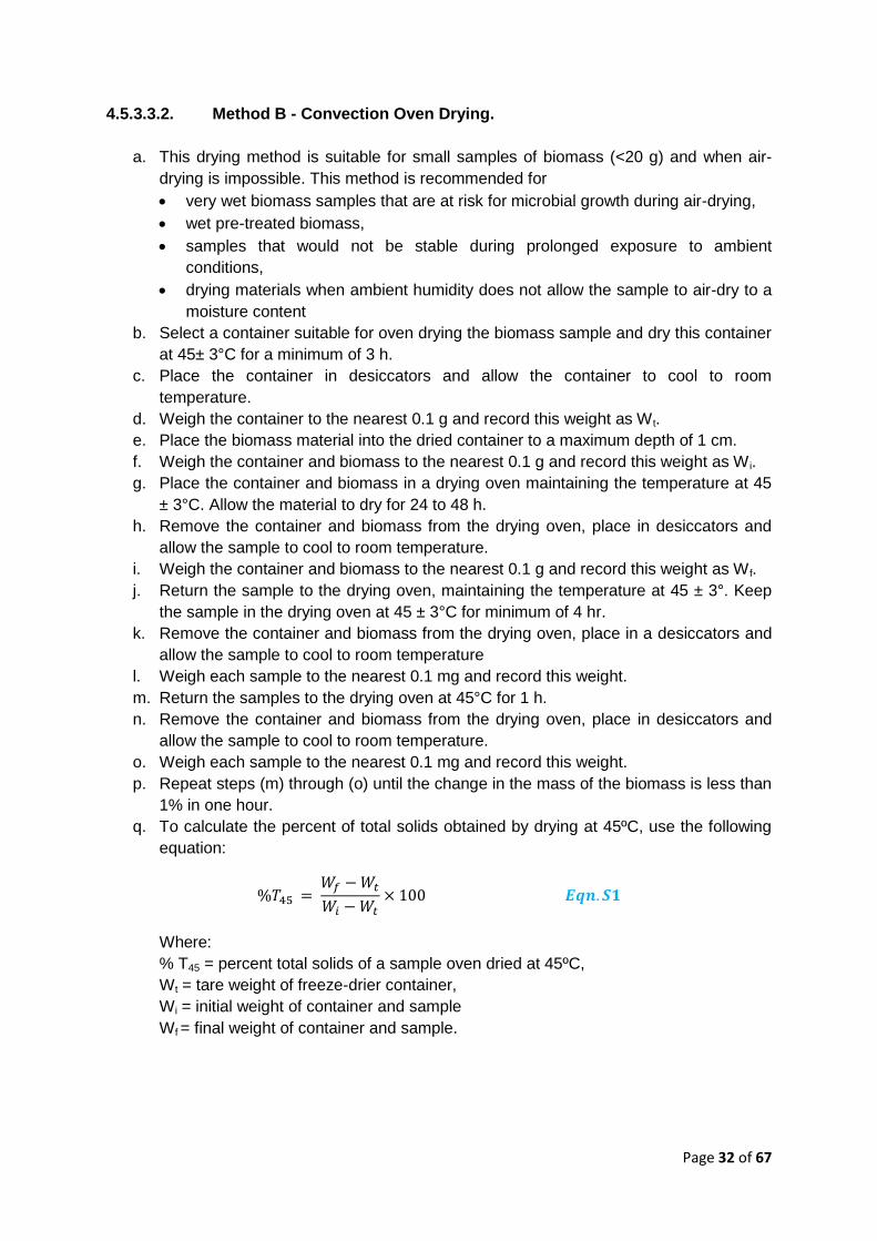
q. To calculate the percent of total solids obtained by drying at 45ºC, use the following
equation:
Where:
% T45 = percent total solids of a sample oven dried at 45ºC,
Wt = tare weight of freeze-drier container,
Wi = initial weight of container and sample
Wf = final weight of container and sample.
Page 33 of 67
4.5.3.3.3. Method C – Lyophilization (freeze-drying).
a. This drying method is suitable for small samples of biomass (<20 g).
b. This method is recommended for
very wet biomass that is at risk for microbial growth during air-drying
wet pre-treated biomass
samples that would not be stable during prolonged exposure to ambient
conditions
drying materials when ambient humidity does not allow the sample to air-dry to a
moisture content below 10%
materials that are heat sensitive and would degrade if subjected to oven drying
c. Weigh a suitable freeze-drier container to the nearest 0.1 g and record this weight as
Wt.
d. Place the biomass material in the container. For solid samples, do not fill the
container more than half full. For liquid or slurry materials, limit the sample to the
amount of material that gives a uniform coating of around 0.5 cm on the walls of the
container when the sample is frozen.
e. Weigh the container and biomass to the nearest 0.1 g and record this weight as W i.
f. Combine the dry ice and acetone in a shallow container suitable for shell freezing.
g. Place the freeze dry flask containing the biomass sample in the dry ice acetone
mixture. Slowly turn the container (10 rev/min) to freeze the material into a uniform
layer on the walls of the container.
h. Immediately place the container on the freeze-drier and allow the material to dry until
all visible traces of ice and frost are gone from the sample. This process typically
takes 12 hours for small (<20 g) samples, and can extend to more than 96 hours for
large samples (>250 g).
i. Remove the container and biomass from the freeze drier.
j. Allow the sample to warm to room temperature.
k. Weigh the container and biomass to the nearest 0.1 g and record this weight as W f.
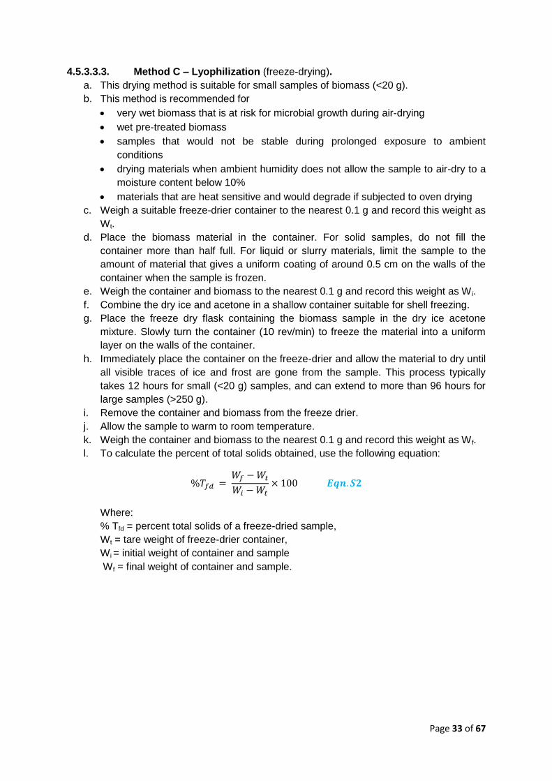
l. To calculate the percent of total solids obtained, use the following equation:
Where:
% Tfd = percent total solids of a freeze-dried sample,
Wt = tare weight of freeze-drier container,
Wi = initial weight of container and sample
Wf = final weight of container and sample.
Page 34 of 67
4.5.3.4. Sample Milling Procedure
The followings are guideline for sample milling:
a. Feed the air-dried biomass into the knife-mill, and mill until the entire sample passes
through the 2 mm screen in the bottom of the mill, or a 1mm screen on small mills.
Laboratory mills can generate enough heat to damage biomass samples.
b. Monitor the mill closely and allow the mill to cool to room temperature between
batches if necessary.
c. If the prepared sample is not analysed immediately, the sample should be stored in
an airtight container or sealable polyethylene bag and kept at -20°C until needed.
4.5.3.5. Sample Sieving Procedure
Sieving shall be performed if
a. The ash content is high. ASTM E1755 - 01(2007) Standard Test Method for Ash in
Biomass can be used as reference test procedure
b. Homogeneous particle size is a critical.
However, if the entire biomass sample needs to be analysed, sieving can frequently cause
fractionation and should not be performed. The followings are guideline for sample sieving:
a. Stack the sieves in the following order, starting at the bottom: solid catch pan, 80-
mesh sieve, 20-mesh sieve.
b. Place the milled biomass in the 20-mesh sieve. The sample should be no more than
7 cm deep in the 20-mesh sieve. The milled sample may be processed in batches if
necessary.
c. Place the cover on the sieve stack and secure the stack in the sieve shaker.
d. Shake the sieves for 15 ± 1 min.
e. The fraction retained on the 20-mesh sieve (+20 mesh fraction) should be
reprocessed (knife-mill until the entire sample passes through the 2 mm screen in the
bottom of the mill, or a 1mm screen on small mills) until no biomass remains on the
20-mesh sieve.
f. The fraction retained on the 80-mesh sieve (-20/+80 mesh fraction) should be
retained for compositional analysis.
g. The material in the solid catch pan is the fines (-80mesh) fraction. Retain this
material for ash analysis.
h. Combine all of the -20/+80 mesh batches. Weigh the combined -20/+80 mesh
fraction to the nearest 0.1 g. Record the weight of the -20/+80 mesh fraction as
Wt20/80.
i. Combine all of -80 mesh batches. Weigh the combined fines to the nearest 0.1 g.
Record the weight of fines fraction as Wt80.
j. If multiple sieved samples were combined they must homogenized. Pour the - 20/+80
mesh fraction into the riffle sampler. The sample must be distributed evenly onto all
the riffle openings. A pan, as wide as the riffle opening, should be used. Pour the
sample evenly off the entire side of the pan and not from the end or the corner. Do
not transfer the biomass sample from a narrow-mouth container such as a jar.
k. Recombine the riffled sub-samples.
l. Repeat steps (j) through (k) a total of four times.
Page 35 of 67
m. Determine the total solids content (TS) of both the –20/+80 mesh fraction and the
fines fraction using one of the methods described above. Record the total solids of
the -20/+80 mesh fraction as TS20/80. Record the total solids content of the fines as
TS-80.
n. Determine the ash content of each fraction and record the ash content of the -20/+80
mesh fraction as Ash20/80. Record the ash content of the fines as Ash-80. The
ASTM E1755 - 01(2007) Standard Test Method for Ash in Biomass can be used as
reference test procedure
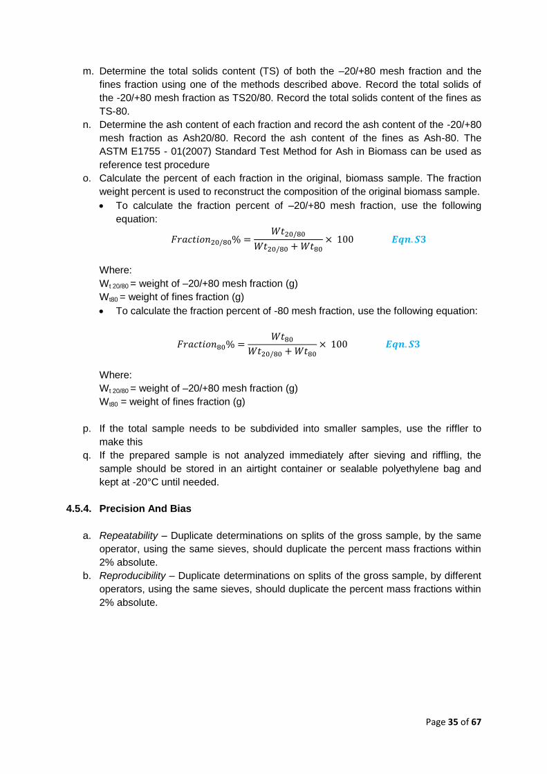
o. Calculate the percent of each fraction in the original, biomass sample. The fraction
weight percent is used to reconstruct the composition of the original biomass sample.
To calculate the fraction percent of –20/+80 mesh fraction, use the following
equation:
Where:
Wt 20/80 = weight of –20/+80 mesh fraction (g)
Wt80 = weight of fines fraction (g)
To calculate the fraction percent of -80 mesh fraction, use the following equation:
Where:
Wt 20/80 = weight of –20/+80 mesh fraction (g)
Wt80 = weight of fines fraction (g)
p. If the total sample needs to be subdivided into smaller samples, use the riffler to
make this
q. If the prepared sample is not analyzed immediately after sieving and riffling, the
sample should be stored in an airtight container or sealable polyethylene bag and
kept at -20°C until needed.
4.5.4. Precision And Bias
a. Repeatability – Duplicate determinations on splits of the gross sample, by the same
operator, using the same sieves, should duplicate the percent mass fractions within
2% absolute.
b. Reproducibility – Duplicate determinations on splits of the gross sample, by different
operators, using the same sieves, should duplicate the percent mass fractions within
2% absolute.
Page 36 of 67
4.5.5. Reference procedure for Sample Analysis
The followings are recommended standard test method to be used for fuel sample
analysis:
a. ASME E870 Standard Test Methods for Analysis of Woods Fuels shall be used as
standard reference for compositions analysis.
b. ASTM E871 Standard Test Methods for Volatile Matter in the Analysis Sample of
Refuse-derived Fuel
c. ASTM D1102 Standard Test Methods for Ash in Wood
d. ASTM E711 Standard Bomb Calorimeter Test Method for Gross Calorific Value of
Refuse-derived Fuel
e. ASTM E777 Standard Test Methods for Carbon and Hydrogen in the Analysis
Sample of Refuse-derived Fuel
f. ASTM E778 Standard Test Methods for Nitrogen in the Analysis Sample of Refuse-
derived Fuel
g. ASTM E775 Standard Test Methods for Total Sulphur in the Analysis Sample of
Refuse-derived Fuel
4.6. Calibration of Test Instrumentations
a. All instruments used for measurement must be calibrated before the test.
b. Valid equipment and measuring instruments calibrations report must be included in
the full test report. Validity of calibrated equipment and measuring instruments shall
be as stated in the calibration test certificate.
c. All properties evaluation must be performed by SAMM Accredited Laboratory, in
compliance to ISO/IEC 17025 or its equivalent
Page 37 of 67
PART 5 TEST DATA AND RESULTS ANALYSIS
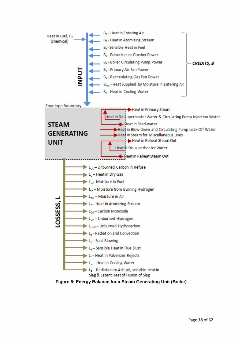
5.1. Steam Generating Unit / Boiler Performance
In a steam generating unit, Energy Input, Ein is defined as the chemical heat in the fuel (high
heat value, HHV of the fuel as determined from laboratory analysis) plus heat credits added
to the working fluid/air/gas and other fluid circuits which cross the envelope boundary. For
biomass, the HHV is determined based on ASTM E711 Standard Bomb Calorimeter Test
Method for Gross Calorific Value of Refuse-derived Fuel. Heat credits, B are the heat added
to the envelope of steam generating unit other than the chemical heat in the fuel. The
Energy Output Eout is defined as the heat absorbed by the working fluid or fluids. The
relationship between Energy Input, Ein, Energy Output Eout, Heat credits, B and Losses, L is
presented in Fig. 5. For the purpose of performance assessment, the envelope boundary
which encompasses all the equipment in the specific steam generating unit must be
established.
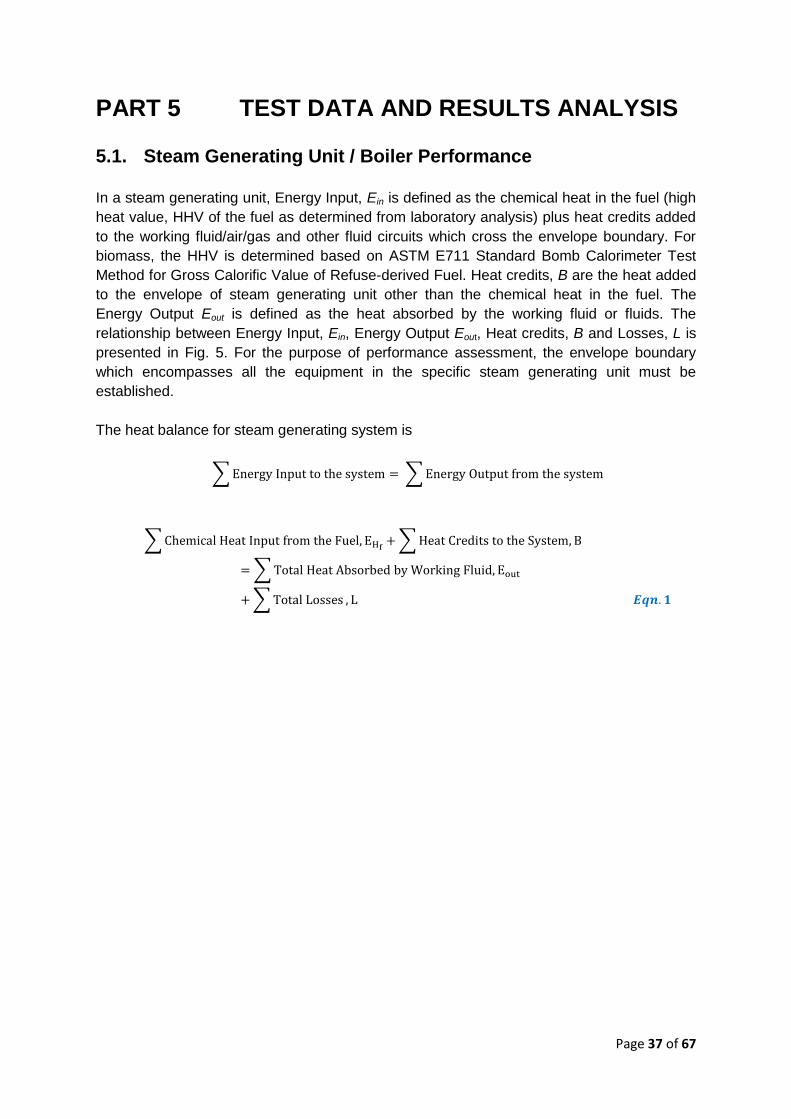
The heat balance for steam generating system is
∑ ∑
∑ ∑
∑
∑
Page 38 of 67
Figure 5: Energy Balance for a Steam Generating Unit (Boiler)
Page 39 of 67
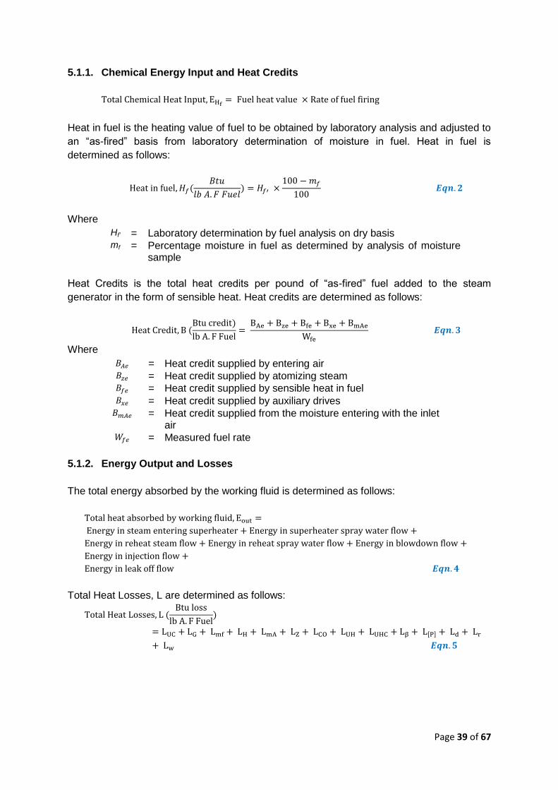
5.1.1. Chemical Energy Input and Heat Credits
Heat in fuel is the heating value of fuel to be obtained by laboratory analysis and adjusted to
an “as-fired” basis from laboratory determination of moisture in fuel. Heat in fuel is
determined as follows:
Where
Hf’ = Laboratory determination by fuel analysis on dry basis mf = Percentage moisture in fuel as determined by analysis of moisture
sample
Heat Credits is the total heat credits per pound of “as-fired” fuel added to the steam
generator in the form of sensible heat. Heat credits are determined as follows:
Where
= Heat credit supplied by entering air = Heat credit supplied by atomizing steam = Heat credit supplied by sensible heat in fuel = Heat credit supplied by auxiliary drives = Heat credit supplied from the moisture entering with the inlet
air = Measured fuel rate
5.1.2. Energy Output and Losses
The total energy absorbed by the working fluid is determined as follows:
Total Heat Losses, L are determined as follows:
[ ]
Page 40 of 67
Where
LUC = Heat loss due to unburned carbon in refuse LG’ = Heat loss due to heat in dry flue gas Lmf = Heat loss due to moisture in the “as-fired” fuel LH = Heat loss due to moisture from burning of hydrogen LmA = Heat loss due to moisture in the air LZ = Heat loss due to heat in atomizing steam
LCO = Heat loss due to formation of carbon monoxide LUH = Heat loss due to unburned hydrogen LUHC = Heat loss due to unburned hydrocarbons
L = Heat loss due to surface radiation and convection L[P] = Heat loss due to radiation to ash-pit, sensible heat in slag Ld = Heat loss due to sensible heat in flue dust Lr = Heat loss due to heat in pulveriser rejects Lw = Heat loss due to heat pickup by cooling water entering
envelope
5.1.3. Efficiency
Boiler efficiency and operating capacity are the commonly accepted indicators for boiler
performance. Typical biomass plant operates with efficiency in the range 7~27% on HHV
basis. Performance efficiency of a steam generating unit shall be based on its gross
efficiency. However, abbreviated efficiency is acceptable for routine testing / acceptance
test of a small steam generating unit. Abbreviated efficiency only considers major losses
which are:
LUC = Heat loss due to unburned carbon in refuse LG’ = Heat loss due to heat in dry flue gas Lmf = Heat loss due to moisture in the “as-fired” fuel LH = Heat loss due to moisture from burning of hydrogen
L = Heat loss due to surface radiation and convection
Two methods can be used for efficiency calculation – the Input/ Output Method and the Heat
Loss Method. The Heat Loss Method is more accurate and preferable because it considers
all the Losses and Heat Credits. For a steam generating unit, ASME PTC 4 Performance
Test Code for Fired Steam Generators and TIP 0416-18 Performance Test Procedure for
Boilers Using Biomass as Fuel shall be used as reference. Efficiency is calculated based on
accurate data on accountable losses and heat credits. Based on Heat Loss Method,
(
)
Page 41 of 67
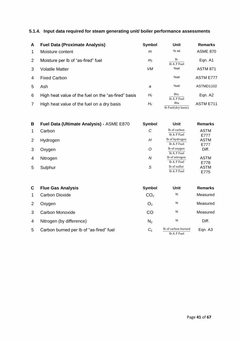
5.1.4. Input data required for steam generating unit/ boiler performance assessments
A Fuel Data (Proximate Analysis) Symbol Unit Remarks
1 Moisture content m % wt ASME 870
2 Moisture per lb of “as-fired” fuel mf
Eqn. A1
3 Volatile Matter VM %wt ASTM 871
4 Fixed Carbon %wt ASTM E777
5 Ash a %wt ASTMD1102
6 High heat value of the fuel on the “as-fired” basis Hf
Eqn. A2
7 High heat value of the fuel on a dry basis Hf’
ASTM E711
B Fuel Data (Ultimate Analysis) - ASME E870 Symbol Unit Remarks
1 Carbon C
ASTM
E777
2 Hydrogen H
ASTM
E777
3 Oxygen O
Diff.
4 Nitrogen N
ASTM
E778
5 Sulphur S
ASTM
E775
C Flue Gas Analysis Symbol Unit Remarks
1 Carbon Dioxide CO2 % Measured
2 Oxygen O2 % Measured
3 Carbon Monoxide CO % Measured
4 Nitrogen (by difference) N2 % Diff.
5 Carbon burned per lb of “as-fired” fuel Cb
Eqn. A3
Page 42 of 67
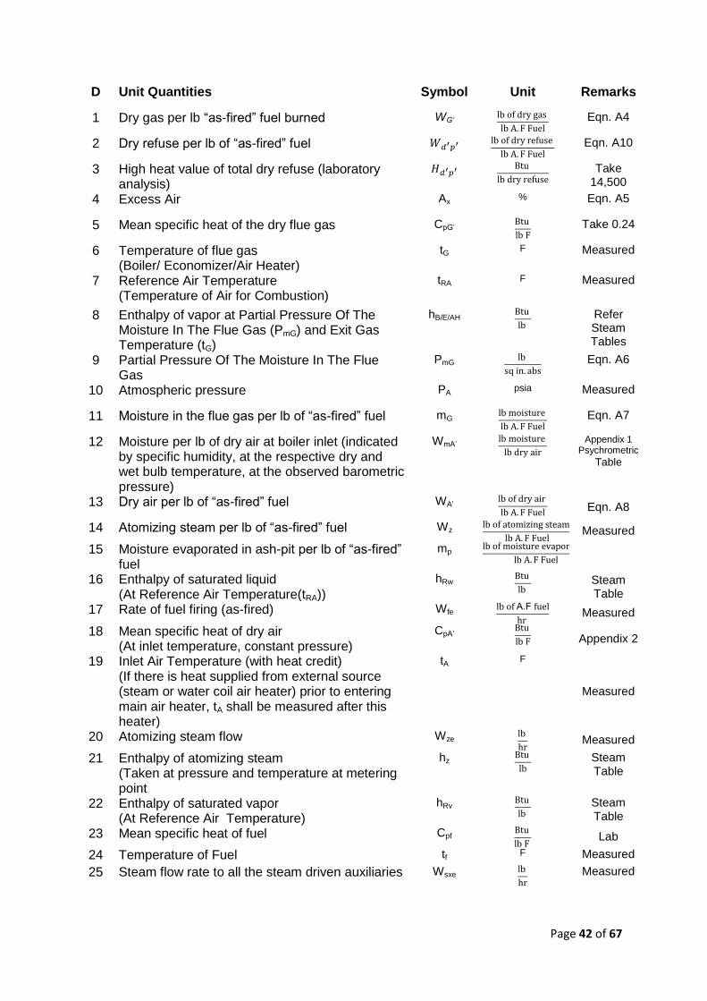
D Unit Quantities Symbol Unit Remarks
1 Dry gas per lb “as-fired” fuel burned WG’
Eqn. A4
2 Dry refuse per lb of “as-fired” fuel
Eqn. A10
3 High heat value of total dry refuse (laboratory analysis)
Take
14,500
4 Excess Air Ax % Eqn. A5
5 Mean specific heat of the dry flue gas CpG’
Take 0.24
6 Temperature of flue gas (Boiler/ Economizer/Air Heater)
tG F Measured
7 Reference Air Temperature (Temperature of Air for Combustion)
tRA F Measured
8 Enthalpy of vapor at Partial Pressure Of The Moisture In The Flue Gas (PmG) and Exit Gas Temperature (tG)
hB/E/AH
Refer
Steam Tables
9 Partial Pressure Of The Moisture In The Flue Gas
PmG
Eqn. A6
10 Atmospheric pressure PA psia Measured
11 Moisture in the flue gas per lb of “as-fired” fuel mG
Eqn. A7
12 Moisture per lb of dry air at boiler inlet (indicated by specific humidity, at the respective dry and wet bulb temperature, at the observed barometric pressure)
WmA’
Appendix 1 Psychrometric
Table
13 Dry air per lb of “as-fired” fuel WA’
Eqn. A8
14 Atomizing steam per lb of “as-fired” fuel Wz
Measured
15 Moisture evaporated in ash-pit per lb of “as-fired” fuel
mp
16 Enthalpy of saturated liquid (At Reference Air Temperature(tRA))
hRw
Steam
Table
17 Rate of fuel firing (as-fired) Wfe A.F
Measured
18 Mean specific heat of dry air (At inlet temperature, constant pressure)
CpA’
Appendix 2
19 Inlet Air Temperature (with heat credit) (If there is heat supplied from external source (steam or water coil air heater) prior to entering main air heater, tA shall be measured after this heater)
tA F
Measured
20 Atomizing steam flow Wze
Measured
21 Enthalpy of atomizing steam (Taken at pressure and temperature at metering point
hz
Steam
Table
22 Enthalpy of saturated vapor (At Reference Air Temperature)
hRv
Steam
Table
23 Mean specific heat of fuel Cpf
Lab
24 Temperature of Fuel tf F Measured
25 Steam flow rate to all the steam driven auxiliaries Wsxe
Measured
Page 43 of 67
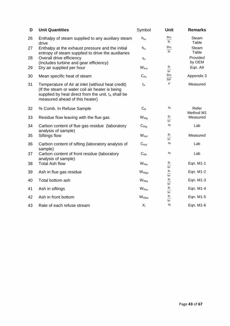
D Unit Quantities Symbol Unit Remarks
26 Enthalpy of steam supplied to any auxiliary steam drive
hsx
Steam
Table
27 Enthalpy at the exhaust pressure and the initial entropy of steam supplied to drive the auxiliaries
hix
Steam
Table
28 Overall drive efficiency (Includes turbine and gear efficiency)
x Provided by OEM
29 Dry air supplied per hour WA’e
Eqn. A9
30 Mean specific heat of steam CPs
Appendix 3
31 Temperature of Air at inlet (without heat credit) (If the steam or water coil air heater is being supplied by heat direct from the unit, tA shall be measured ahead of this heater)
tA F Measured
32 % Comb. In Refuse Sample CR % Refer Method M1
33 Residue flow leaving with the flue gas WRfg
Measured
34 Carbon content of flue gas residue (laboratory analysis of sample)
CRfg % Lab
35 Siftings flow WRsf
Measured
36 Carbon content of sifting (laboratory analysis of sample)
CRsf % Lab
37 Carbon content of front residue (laboratory analysis of sample)
CRfr % Lab
38 Total Ash flow WRta
Eqn. M1-1
39 Ash in flue gas residue WRfga
Eqn. M1-2
40 Total bottom ash WRba
Eqn. M1-3
41 Ash in siftings WRsa
Eqn. M1-4
42 Ash in front bottom WRfba
Eqn. M1-5
43 Rate of each refuse stream Xi % Eqn. M1-6
Page 44 of 67
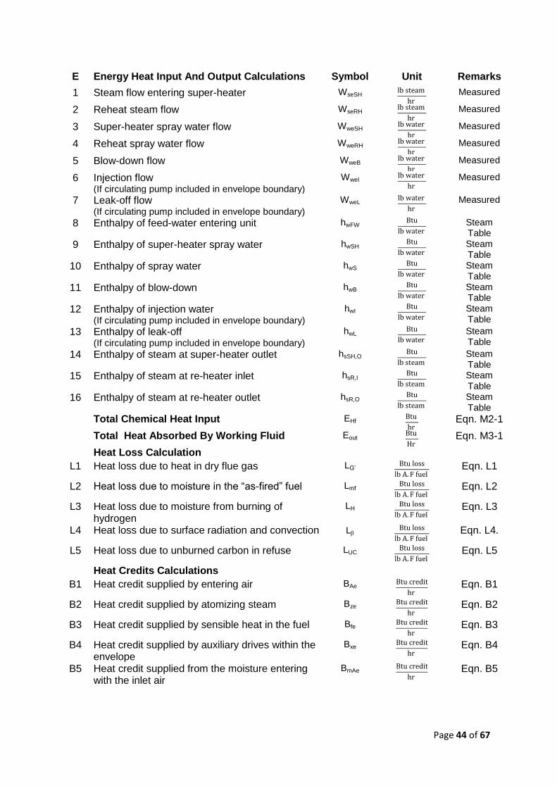
E Energy Heat Input And Output Calculations Symbol Unit Remarks
1 Steam flow entering super-heater WseSH
Measured
2 Reheat steam flow WseRH
Measured
3 Super-heater spray water flow WweSH
Measured
4 Reheat spray water flow WweRH
Measured
5 Blow-down flow WweB
Measured
6 Injection flow (If circulating pump included in envelope boundary)
WweI
Measured
7 Leak-off flow (If circulating pump included in envelope boundary)
WweL
Measured
8 Enthalpy of feed-water entering unit hwFW
Steam
Table
9 Enthalpy of super-heater spray water hwSH
Steam
Table 10 Enthalpy of spray water hwS
Steam
Table 11 Enthalpy of blow-down hwB
Steam
Table 12 Enthalpy of injection water
(If circulating pump included in envelope boundary) hwI
Steam
Table
13 Enthalpy of leak-off (If circulating pump included in envelope boundary)
hwL
Steam
Table
14 Enthalpy of steam at super-heater outlet hsSH,O
Steam
Table 15 Enthalpy of steam at re-heater inlet hsR,I
Steam
Table 16 Enthalpy of steam at re-heater outlet hsR,O
Steam
Table Total Chemical Heat Input EHf
Eqn. M2-1
Total Heat Absorbed By Working Fluid Eout
Eqn. M3-1
Heat Loss Calculation
L1 Heat loss due to heat in dry flue gas LG’
Eqn. L1
L2 Heat loss due to moisture in the “as-fired” fuel Lmf
Eqn. L2
L3 Heat loss due to moisture from burning of hydrogen
LH
Eqn. L3
L4 Heat loss due to surface radiation and convection L
Eqn. L4.
L5 Heat loss due to unburned carbon in refuse LUC
Eqn. L5
Heat Credits Calculations
B1 Heat credit supplied by entering air BAe
Eqn. B1
B2 Heat credit supplied by atomizing steam Bze
Eqn. B2
B3 Heat credit supplied by sensible heat in the fuel Bfe
Eqn. B3
B4 Heat credit supplied by auxiliary drives within the envelope
Bxe
Eqn. B4
B5 Heat credit supplied from the moisture entering with the inlet air
BmAe
Eqn. B5
Page 45 of 67
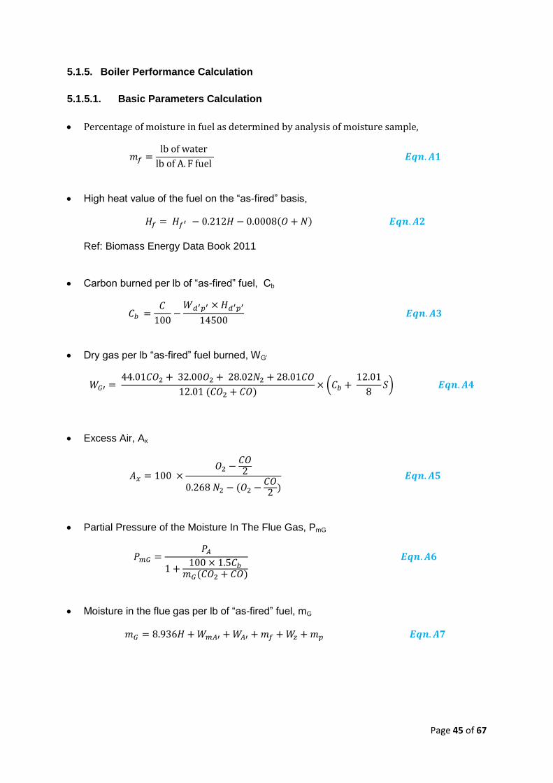
5.1.5. Boiler Performance Calculation
5.1.5.1. Basic Parameters Calculation
High heat value of the fuel on the “as-fired” basis,
Ref: Biomass Energy Data Book 2011
Carbon burned per lb of “as-fired” fuel, Cb
Dry gas per lb “as-fired” fuel burned, WG’
(
)
Excess Air, Ax
Partial Pressure of the Moisture In The Flue Gas, PmG
Moisture in the flue gas per lb of “as-fired” fuel, mG
Page 46 of 67
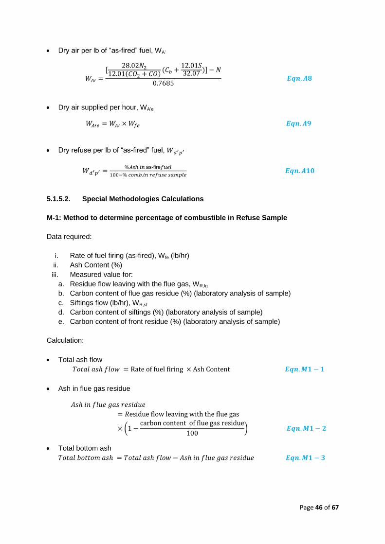
Dry air per lb of “as-fired” fuel, WA’
[
]
Dry air supplied per hour, WA’e
Dry refuse per lb of “as-fired” fuel,
as-fire
5.1.5.2. Special Methodologies Calculations
M-1: Method to determine percentage of combustible in Refuse Sample
Data required:
i. Rate of fuel firing (as-fired), Wfe (lb/hr)
ii. Ash Content (%)
iii. Measured value for:
a. Residue flow leaving with the flue gas, WR,fg
b. Carbon content of flue gas residue (%) (laboratory analysis of sample)
c. Siftings flow (lb/hr), WR,sf
d. Carbon content of siftings (%) (laboratory analysis of sample)
e. Carbon content of front residue (%) (laboratory analysis of sample)
Calculation:
Total ash flow
Ash in flue gas residue
(
)
Total bottom ash
Page 47 of 67
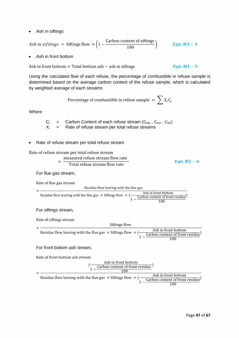
Ash in siftings
(
)
Ash in front bottom
Using the calculated flow of each refuse, the percentage of combustible in refuse sample is
determined based on the average carbon content of the refuse sample, which is calculated
by weighted average of each streams
∑
Where
Ci = Carbon Content of each refuse stream (CRfg , CRsf , CRfr)
Xi = Rate of refuse stream per total refuse streams
Rate of refuse stream per total refuse stream
For flue gas stream,
For siftings stream,
For front bottom ash stream,
Page 48 of 67
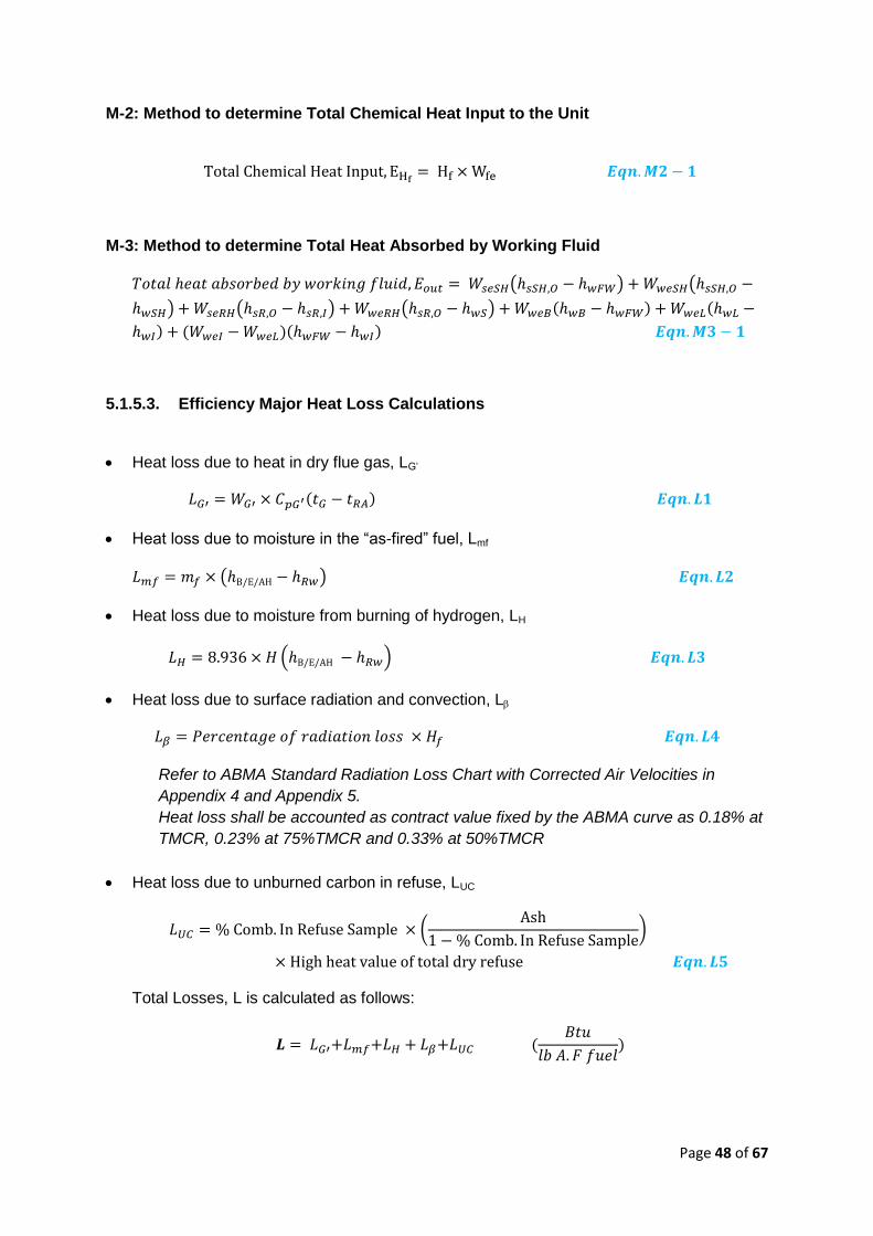
M-2: Method to determine Total Chemical Heat Input to the Unit
M-3: Method to determine Total Heat Absorbed by Working Fluid
( ) (
) ( ) ( )
5.1.5.3. Efficiency Major Heat Loss Calculations
Heat loss due to heat in dry flue gas, LG’
Heat loss due to moisture in the “as-fired” fuel, Lmf
( )
Heat loss due to moisture from burning of hydrogen, LH
( )
Heat loss due to surface radiation and convection, L
Refer to ABMA Standard Radiation Loss Chart with Corrected Air Velocities in
Appendix 4 and Appendix 5.
Heat loss shall be accounted as contract value fixed by the ABMA curve as 0.18% at
TMCR, 0.23% at 75%TMCR and 0.33% at 50%TMCR
Heat loss due to unburned carbon in refuse, LUC
(
)
Total Losses, L is calculated as follows:
Page 49 of 67
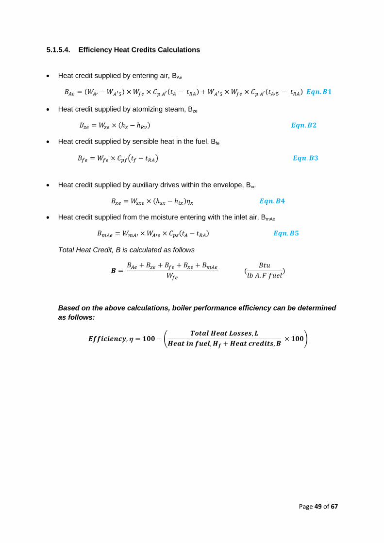
5.1.5.4. Efficiency Heat Credits Calculations
Heat credit supplied by entering air, BAe
Heat credit supplied by atomizing steam, Bze
Heat credit supplied by sensible heat in the fuel, Bfe
( )
Heat credit supplied by auxiliary drives within the envelope, Bxe
Heat credit supplied from the moisture entering with the inlet air, BmAe
Total Heat Credit, B is calculated as follows
Based on the above calculations, boiler performance efficiency can be determined
as follows:
(
)
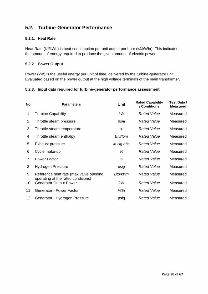
Page 50 of 67
5.2. Turbine-Generator Performance
5.2.1. Heat Rate
Heat Rate (kJ/kWh) is heat consumption per unit output per hour (kJ/kWhr). This indicates
the amount of energy required to produce the given amount of electric power.
5.2.2. Power Output
Power (kW) is the useful energy per unit of time, delivered by the turbine-generator unit.
Evaluated based on the power output at the high voltage terminals of the main transformer.
5.2.3. Input data required for turbine-generator performance assessment
No Parameters Unit Rated Capability
/ Conditions Test Data / Measured
1 Turbine Capability kW Rated Value Measured
2 Throttle steam pressure psia Rated Value Measured
3 Throttle steam temperature F Rated Value Measured
4 Throttle steam enthalpy Btu/lbm Rated Value Measured
5 Exhaust pressure in Hg abs Rated Value Measured
6 Cycle make-up % Rated Value Measured
7 Power Factor % Rated Value Measured
8 Hydrogen Pressure psig Rated Value Measured
9 Reference heat rate (max valve opening, operating at the rated conditions)
Btu/kWh Rated Value Measured
10 Generator Output Power kW Rated Value Measured
11 Generator - Power Factor %% Rated Value Measured
12 Generator - Hydrogen Pressure psig Rated Value Measured
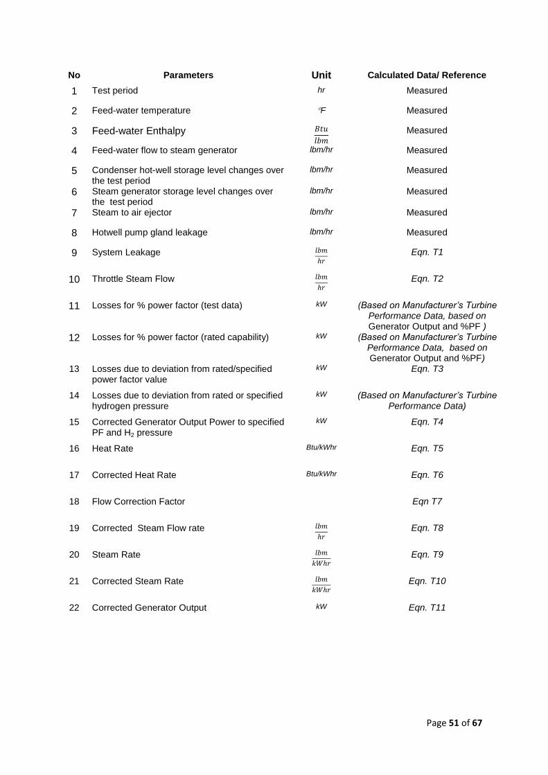
Page 51 of 67
No Parameters Unit Calculated Data/ Reference
1 Test period hr Measured
2 Feed-water temperature F Measured
3 Feed-water Enthalpy
Measured
4 Feed-water flow to steam generator lbm/hr Measured
5 Condenser hot-well storage level changes over the test period
lbm/hr Measured
6 Steam generator storage level changes over the test period
lbm/hr Measured
7 Steam to air ejector lbm/hr Measured
8 Hotwell pump gland leakage lbm/hr Measured
9 System Leakage
Eqn. T1
10 Throttle Steam Flow
Eqn. T2
11 Losses for % power factor (test data) kW (Based on Manufacturer’s Turbine Performance Data, based on Generator Output and %PF )
12 Losses for % power factor (rated capability) kW (Based on Manufacturer’s Turbine Performance Data, based on Generator Output and %PF)
13 Losses due to deviation from rated/specified power factor value
kW Eqn. T3
14 Losses due to deviation from rated or specified hydrogen pressure
kW (Based on Manufacturer’s Turbine Performance Data)
15 Corrected Generator Output Power to specified PF and H2 pressure
kW Eqn. T4
16 Heat Rate Btu/kWhr Eqn. T5
17 Corrected Heat Rate Btu/kWhr Eqn. T6
18 Flow Correction Factor Eqn T7
19 Corrected Steam Flow rate
Eqn. T8
20 Steam Rate
Eqn. T9
21 Corrected Steam Rate
Eqn. T10
22 Corrected Generator Output kW Eqn. T11
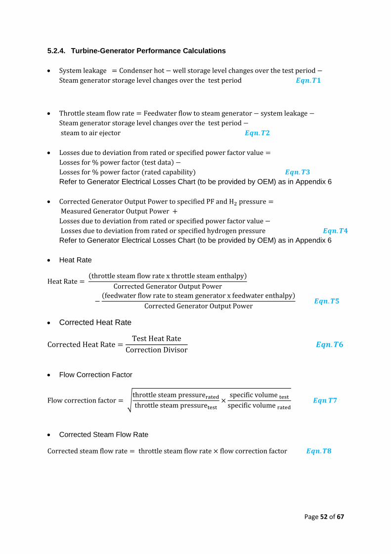
Page 52 of 67
5.2.4. Turbine-Generator Performance Calculations
Refer to Generator Electrical Losses Chart (to be provided by OEM) as in Appendix 6
Refer to Generator Electrical Losses Chart (to be provided by OEM) as in Appendix 6
Heat Rate
Corrected Heat Rate
Flow Correction Factor
√
Corrected Steam Flow Rate
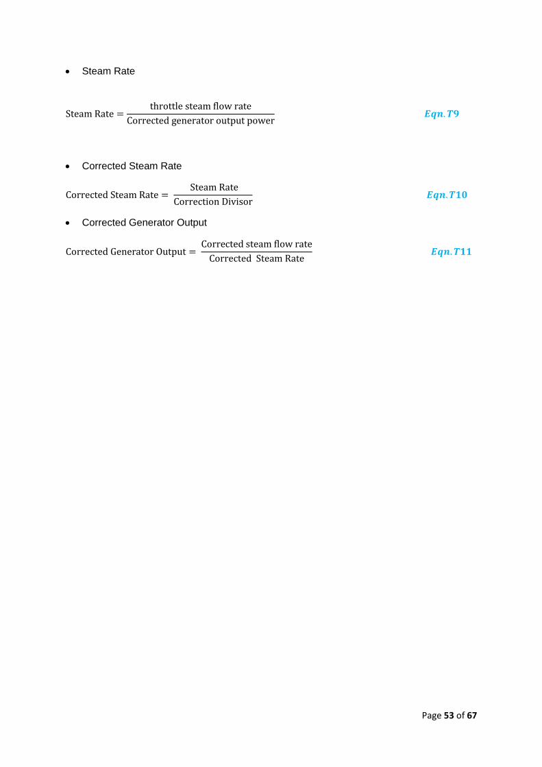
Page 53 of 67
Steam Rate
Corrected Steam Rate
Corrected Generator Output
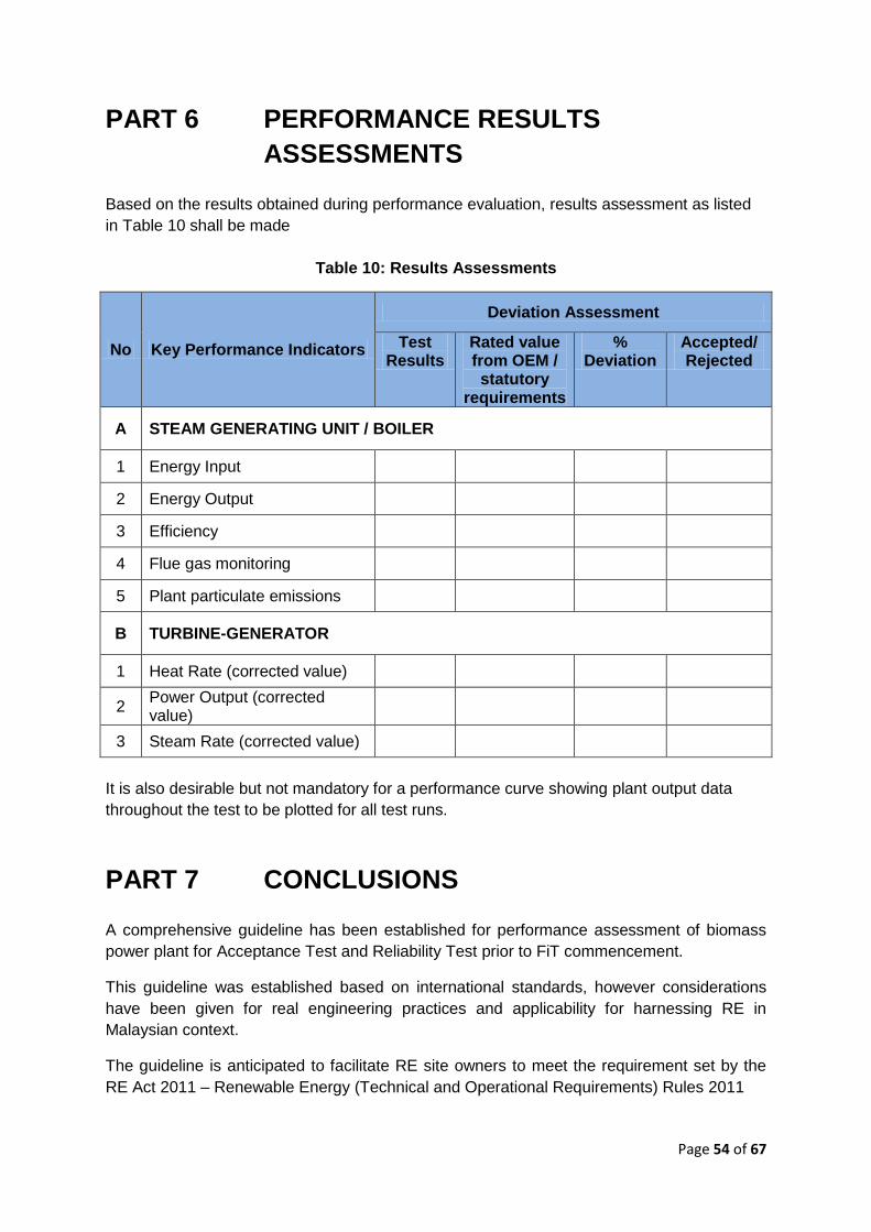
Page 54 of 67
PART 6 PERFORMANCE RESULTS
ASSESSMENTS
Based on the results obtained during performance evaluation, results assessment as listed
in Table 10 shall be made
Table 10: Results Assessments
No Key Performance Indicators
Deviation Assessment
Test Results
Rated value from OEM / statutory
requirements
% Deviation
Accepted/ Rejected
A STEAM GENERATING UNIT / BOILER
1 Energy Input
2 Energy Output
3 Efficiency
4 Flue gas monitoring
5 Plant particulate emissions
B TURBINE-GENERATOR
1 Heat Rate (corrected value)
2 Power Output (corrected value)
3 Steam Rate (corrected value)
It is also desirable but not mandatory for a performance curve showing plant output data
throughout the test to be plotted for all test runs.
PART 7 CONCLUSIONS
A comprehensive guideline has been established for performance assessment of biomass
power plant for Acceptance Test and Reliability Test prior to FiT commencement.
This guideline was established based on international standards, however considerations
have been given for real engineering practices and applicability for harnessing RE in
Malaysian context.
The guideline is anticipated to facilitate RE site owners to meet the requirement set by the
RE Act 2011 – Renewable Energy (Technical and Operational Requirements) Rules 2011
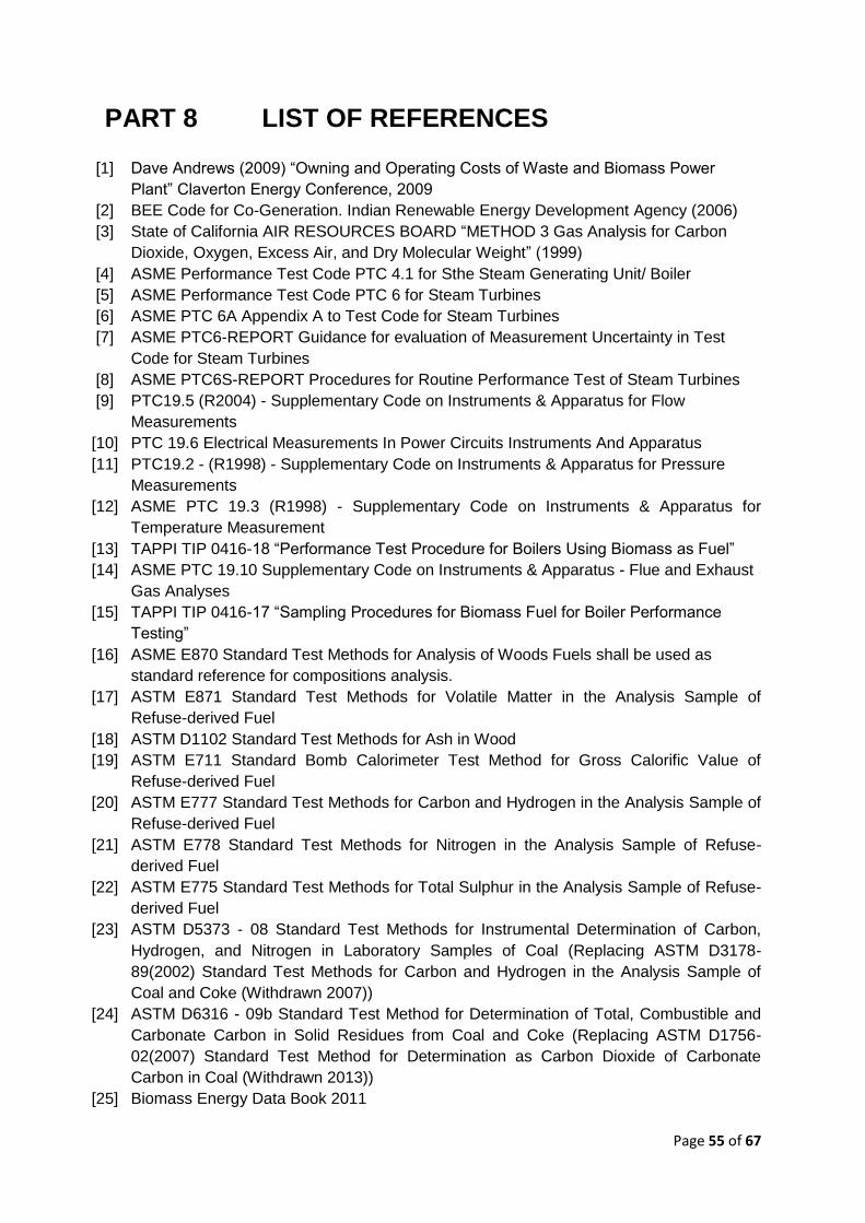
Page 55 of 67
PART 8 LIST OF REFERENCES
[1] Dave Andrews (2009) “Owning and Operating Costs of Waste and Biomass Power
Plant” Claverton Energy Conference, 2009
[2] BEE Code for Co-Generation. Indian Renewable Energy Development Agency (2006)
[3] State of California AIR RESOURCES BOARD “METHOD 3 Gas Analysis for Carbon
Dioxide, Oxygen, Excess Air, and Dry Molecular Weight” (1999)
[4] ASME Performance Test Code PTC 4.1 for Sthe Steam Generating Unit/ Boiler
[5] ASME Performance Test Code PTC 6 for Steam Turbines
[6] ASME PTC 6A Appendix A to Test Code for Steam Turbines
[7] ASME PTC6-REPORT Guidance for evaluation of Measurement Uncertainty in Test
Code for Steam Turbines
[8] ASME PTC6S-REPORT Procedures for Routine Performance Test of Steam Turbines
[9] PTC19.5 (R2004) - Supplementary Code on Instruments & Apparatus for Flow
Measurements
[10] PTC 19.6 Electrical Measurements In Power Circuits Instruments And Apparatus
[11] PTC19.2 - (R1998) - Supplementary Code on Instruments & Apparatus for Pressure
Measurements
[12] ASME PTC 19.3 (R1998) - Supplementary Code on Instruments & Apparatus for
Temperature Measurement
[13] TAPPI TIP 0416-18 “Performance Test Procedure for Boilers Using Biomass as Fuel”
[14] ASME PTC 19.10 Supplementary Code on Instruments & Apparatus - Flue and Exhaust
Gas Analyses
[15] TAPPI TIP 0416-17 “Sampling Procedures for Biomass Fuel for Boiler Performance
Testing”
[16] ASME E870 Standard Test Methods for Analysis of Woods Fuels shall be used as
standard reference for compositions analysis.
[17] ASTM E871 Standard Test Methods for Volatile Matter in the Analysis Sample of
Refuse-derived Fuel
[18] ASTM D1102 Standard Test Methods for Ash in Wood
[19] ASTM E711 Standard Bomb Calorimeter Test Method for Gross Calorific Value of
Refuse-derived Fuel
[20] ASTM E777 Standard Test Methods for Carbon and Hydrogen in the Analysis Sample of
Refuse-derived Fuel
[21] ASTM E778 Standard Test Methods for Nitrogen in the Analysis Sample of Refuse-
derived Fuel
[22] ASTM E775 Standard Test Methods for Total Sulphur in the Analysis Sample of Refuse-
derived Fuel
[23] ASTM D5373 - 08 Standard Test Methods for Instrumental Determination of Carbon,
Hydrogen, and Nitrogen in Laboratory Samples of Coal (Replacing ASTM D3178-
89(2002) Standard Test Methods for Carbon and Hydrogen in the Analysis Sample of
Coal and Coke (Withdrawn 2007))
[24] ASTM D6316 - 09b Standard Test Method for Determination of Total, Combustible and
Carbonate Carbon in Solid Residues from Coal and Coke (Replacing ASTM D1756-
02(2007) Standard Test Method for Determination as Carbon Dioxide of Carbonate
Carbon in Coal (Withdrawn 2013))
[25] Biomass Energy Data Book 2011
Page 56 of 67
[26] BS EN-12952-152003 Water Tube Boilers and Auxiliary Installations : Part 15
Acceptance Test
[27] EPA Method 3, Gas Analysis for Determination of Dry Molecular Weight, CFR40, Part 60
[28] ASTM E1757 - 01(2007) Standard Practice for Preparation of Biomass for Compositional
Analysis
[29] TAPPI Test Method T264 cm-97, "Preparation of wood for chemical analysis" In TAPPI
Test Methosd 2002-2003. Atlanta, GA: Technical Association of the Pulp and Paper
Industry
[30] NREL/TP-510-42620 Analytical Procedure (LAP) for Preparation of Samples for
Compositional Analysis Laboratory, 2008
[31] NREL/TP-510-42621 (2008) Laboratory Analytical Procedure (LAP) for Determination of
Total Solids in Biomass and Total Dissolved Solids in Liquid Process Samples
[32] TAPPI Method T412 om-02. 2002. "Moisture in Pulp, Paper and Paperboard." Test
methods of the Technical Association of the Pulp and Paper Industry 2002-2003.
[33] ASTM E1756 - 08 Standard Test Method for Determination of Total Solids in Biomass
[34] Reference Method EPS 1/RM/8 – “Standard Reference Methods for Source Testing:
Measurement of Emissions of Particulates from Stationary Sources” Environment
Canada Catalogue No. En 49-24/1-8E, ISBN 0-662-21355-6 (1994)

Page 57 of 67
PART 9 LIST OF APPENDIX
Appendix 1 Psychrometric Table
Appendix 2 Specific Heat of Air
Appendix 3 Specific Heat of Steam
Appendix 4 ABMA Standard Radiation Loss Chart
Appendix 5 for ABMA Chart
Appendix 6 Generator Electrical Losses
Appendix 7 Specific Heat of Flue Gas
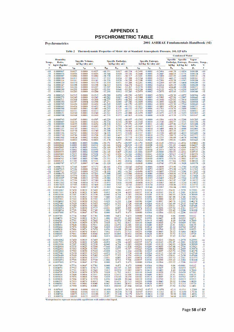
Page 58 of 67
APPENDIX 1
PSYCHROMETRIC TABLE
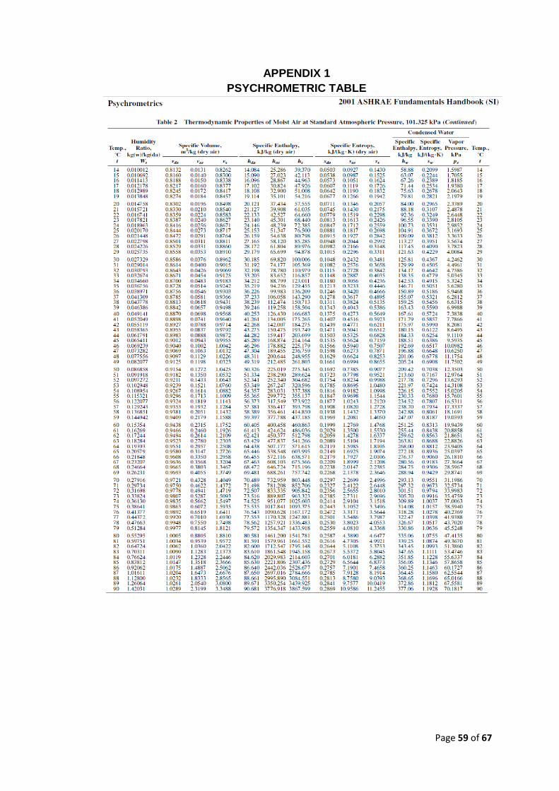
Page 59 of 67
APPENDIX 1
PSYCHROMETRIC TABLE
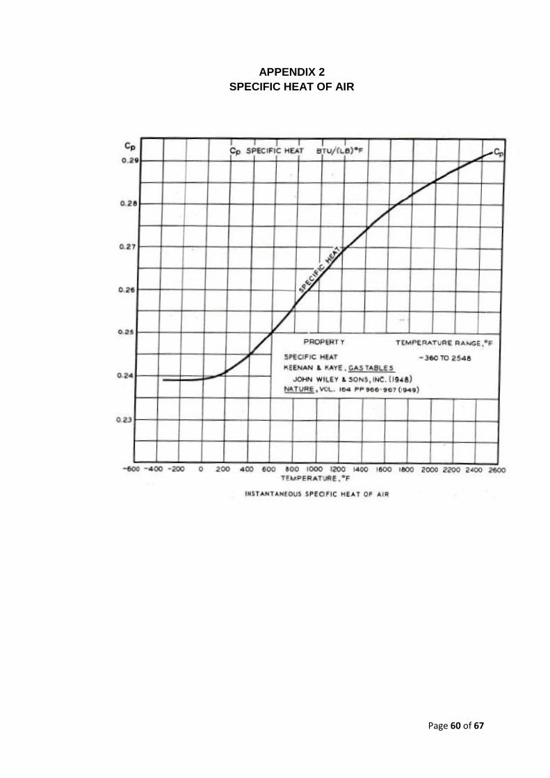
Page 60 of 67
APPENDIX 2
SPECIFIC HEAT OF AIR
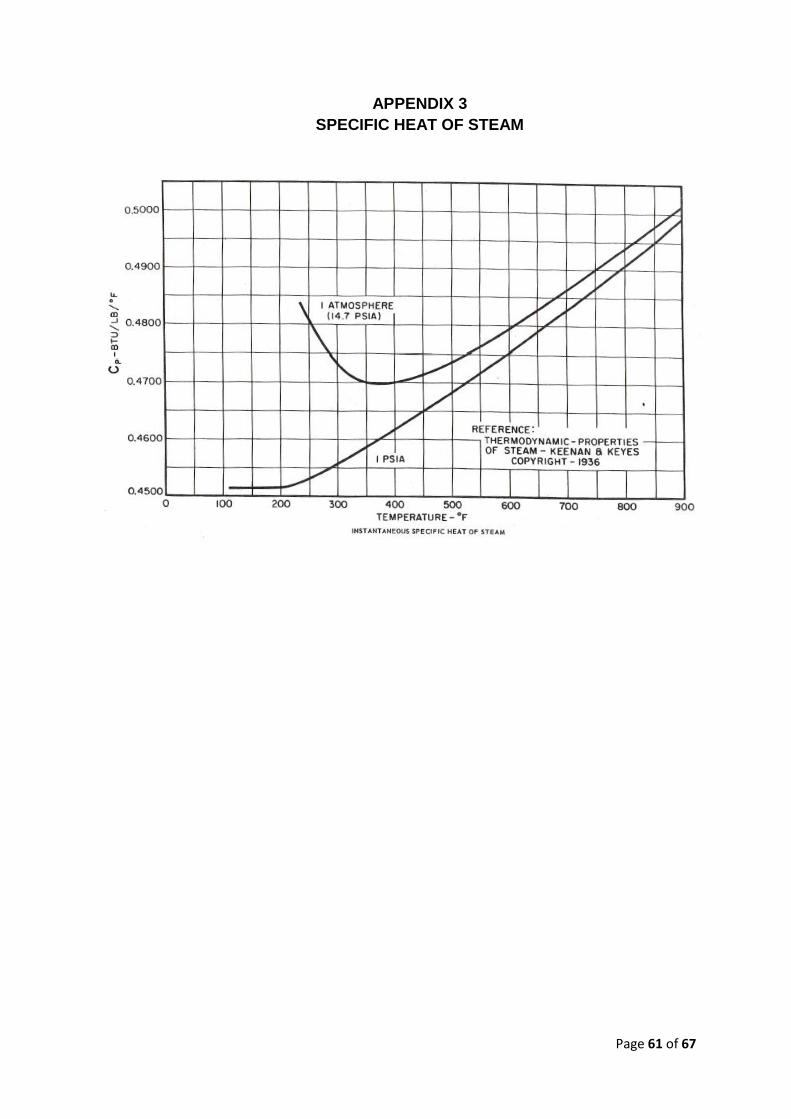
Page 61 of 67
APPENDIX 3
SPECIFIC HEAT OF STEAM

Page 62 of 67
APPENDIX 4
ABMA STANDARD RADIATION LOSS CHART
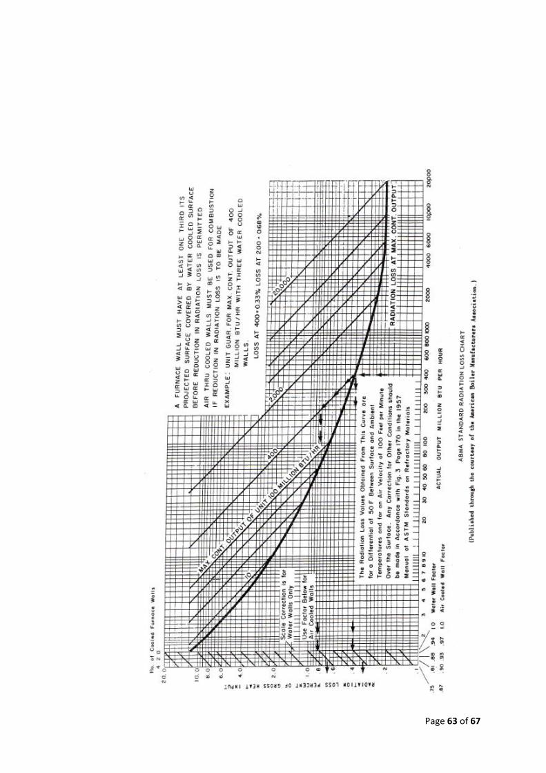
Page 63 of 67
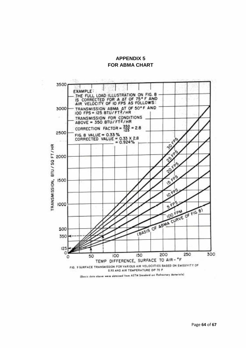
Page 64 of 67
APPENDIX 5
FOR ABMA CHART
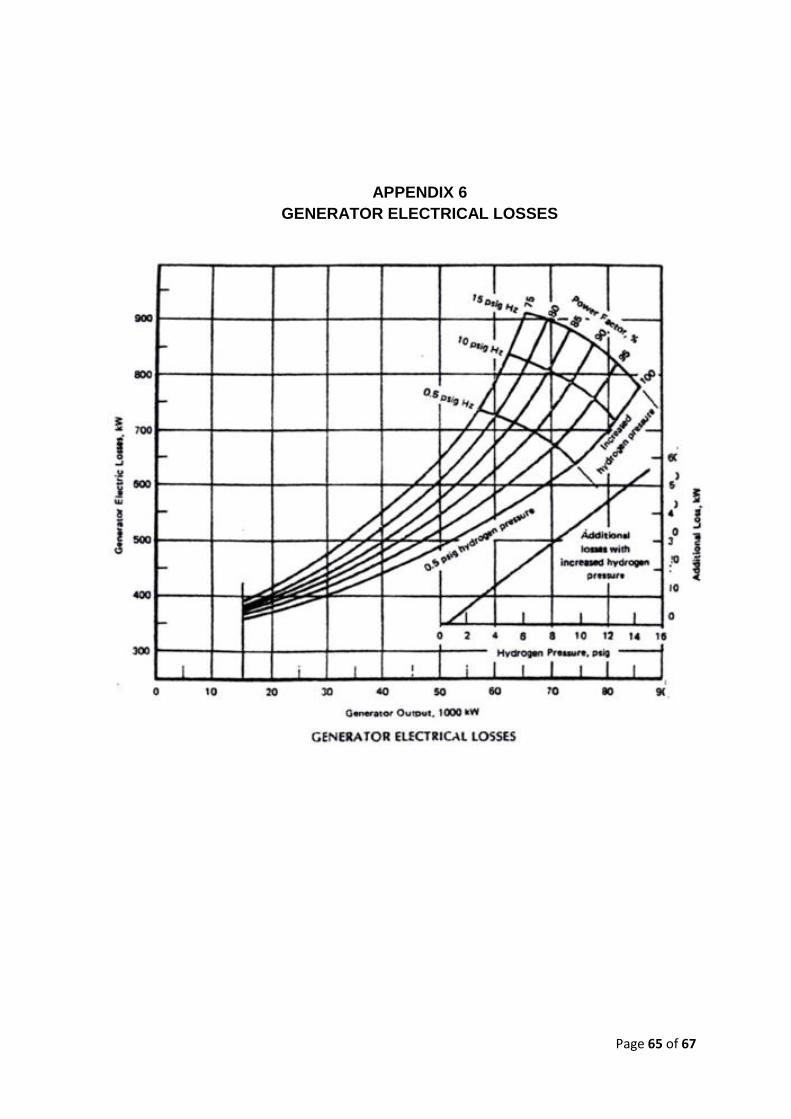
Page 65 of 67
APPENDIX 6
GENERATOR ELECTRICAL LOSSES
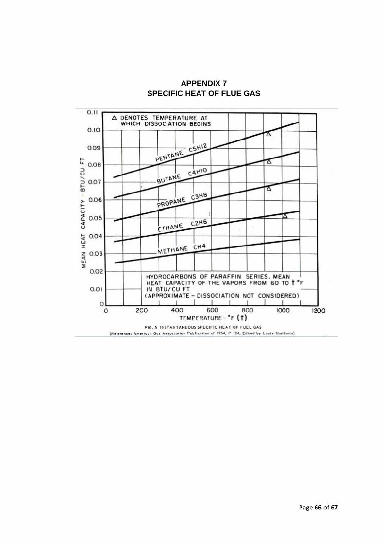
Page 66 of 67
APPENDIX 7
SPECIFIC HEAT OF FLUE GAS