Embed Size (px)
Citation preview

Visit our Web site at:
http://www.thermoscientific.com/tcProduct Service Information, Applications Notes, MSDS Forms, e-mail.
Voice Info: (800) 258-0830
Thermo Scientific ThermoFlexTM Recirculating Chillers (Basic Controller)
Multilingual Quick Start Guides
Installation
Operation
Basic Maintenance
Thermo Scientific Manual P/N U00933
Rev. 05/20/2015


Visit our Web site at:
http://www.thermoscientific.com/tcProduct Service Information, Applications Notes, MSDS Forms, e-mail.
Voice Info: (800) 258-0830
Thermo Scientific ThermoFlexTM Recirculating Chillers (Basic Controller)
Multilingual Quick Start Guides
Installation
Operation
Basic Maintenance
Thermo Scientific Manual P/N U00933 Rev. 05/20/2015
Label 1
Label 2
Thermo Fisher Scientific
25 Nimble Hill RoadNewington, NH 03801Tel : (800) 258-0830 or(603) 436-9444Fax : (603) 436-8411www.thermoscientific.com/tc
Sales, Service, and Customer Support
25 Nimble Hill RoadNewington, NH 03801Tel: (800) 258-0830 Sales: 8:00 am to 5:00 pmService and Support: 8:00 am to 6:00 pm Monday through Friday (Eastern Time)Fax: (603) [email protected]
Dieselstrasse 4 D-76227 Karlsruhe, Germany Tel : +49 (0) 721 4094 444 Fax : +49 (0) 721 4094 [email protected]
Building 6, No. 27Xin Jinqiao Rd., Shanghai 201206Tel : +86(21) 68654588Fax : +86(21) [email protected]
Statement of Copyright Copyright © 2015 Thermo Fisher Scientific. All rights reserved. This manual is copyrighted by Thermo Fisher Scientific. Users are forbidden to reproduce, republish, redistribute, or resell any materials from this manual in either machine-readable form or any other form.
ThermoFlex Thermo Scientific
Contents
Quick Start
Preface .................................................................................................................................i Compliance ..............................................................................................................i WEEE .....................................................................................................................i After-Sale Support .................................................................................................ii Unpacking ...............................................................................................................ii Warranty ..................................................................................................................ii Feedback ..................................................................................................................ii
Section 1 Safety ..................................................................................1-1 Warnings ..............................................................................................................1-1
Section 2 General Information .............................................................2-1 Description .........................................................................................................2-1 Specifications ......................................................................................................2-1
Section 3 Installation ...........................................................................3-1 Site Requirements ..............................................................................................3-1 Electrical Requirements ....................................................................................3-2 Hard Wire Installation .......................................................................................3-8 Plumbing Requirements ....................................................................................3-9 Process Fluid Requirements ...........................................................................3-11 Compatibility with Approved Fluids ............................................................3-12 Additional Fluid Information ........................................................................3-14 Process Water Quality and Standards ...........................................................3-14 Facility Water Quality - Standards and Recommendations .......................3-15 Facility Water Requirements ...........................................................................3-17 Fluid Filter Bag .................................................................................................3-18 Priming ..............................................................................................................3-18 Initial Filling .....................................................................................................3-18 Fluid Top Off ...................................................................................................3-20
Section 4 Operation .........................................................................................................4-1 Basic Controller ..................................................................................................4-1 Setup ....................................................................................................................4-2 Start Up ...............................................................................................................4-2 Controller Loops ................................................................................................4-4 Setpoint Loop .....................................................................................................4-5 Setup Loop ..........................................................................................................4-6 Shut Down ........................................................................................................4-12
ThermoFlex
Contents
Thermo Scientific
Section 5 Additional Options/Accessories ................................................5-1 AutoRefill .........................................................................................................5-1 InternalDICartridge ........................................................................................5-2 P1P2T1PumpPressureRelief Valve(InternalConfiguration) .............. 5-3 P1P2T1PumpPressureRelief Valve(ExternalConfiguration) ............ 5-4 FlowControlwithFlowReadout ....................................................................5-5 P1P2T1PumpPressureRelief withFlowReadout ................................. 5-5 T5PumpFlowControl ....................................................................................5-6 AntiDrainback ...................................................................................................5-6 SEMI ....................................................................................................................5-6 OtherAccessories ............................................................................................5-10
Section 6 Preventive Maintenance............................................................................... 6-1 PreventiveMaintenanceTimer .......................................................................6-1 FluidBagFilter ...................................................................................................6-2 FluidDiffuser .....................................................................................................6-2 ReservoirCleaning .............................................................................................6-3 FluidMaintenance .............................................................................................6-3 CondenserFilter .................................................................................................6-4 ChillerSurface ....................................................................................................6-5 Hoses ...................................................................................................................6-5 DIFilter(Optional) ..........................................................................................6-6 DiagnosticLoop ...............................................................................................6-7 TestingtheAlarmFeatures ..............................................................................6-8
Section 7 Troubleshooting .....................................................................7-1 OperationalErrorCodes ..................................................................................7-1 Checklist ............................................................................................................7-10 Verifying/AdjustingtheControllerPIDValues .........................................7-13
Section 8 Additional Information ............................................................8-1 Draining ...............................................................................................................8-1 WettedMaterials .................................................................................................8-3 InternalProcessFluidTemperatureSensor(rdt1)Calibration ................... 8-4 ProcessFluidPressure(P1)TransducerCalibration ................................... 8-6 OptionalProcessFluidFlow(FLo)TransducerCalibration ...................... 8-8 ClearingSEr1Message ....................................................................................8-10 Decommissioning/Disposal ..........................................................................8-11 Shipment/Storage ............................................................................................8-11
Appendix A CountrySpecific230VAC,50Hz,1ØRequirements
Appendix B VoltageConfigurationInstructions
Appendix C AnalogI/0andRemoteSensor
Appendix D SerialCommunications
Declaration of Conformity WARRANTY
3 C
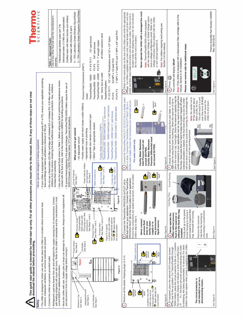
onne
ct th
e Th
erm
oFle
x FA
CIL
ITY
OU
TLE
T (A
) to
a fa
cilit
y w
ater
re
turn
or d
rain
. Con
nect
the
Ther
moF
lex
FAC
ILIT
Y IN
LET
(B) t
o a
faci
lity
wat
er s
uppl
y. E
nsur
e th
e co
nnec
tions
are
sea
led
and
secu
re.
Wha
t you
nee
d to
get
sta
rted
:A
n ad
just
able
wre
nch
Faci
lity
wat
er s
uppl
y an
d re
turn
(wat
er-c
oole
d ch
iller
s)A
ppro
pria
te h
ose
or p
lum
bing
App
ropr
iate
siz
e cl
amps
or c
onne
ctio
n ty
peTeflon®
Tap
e or
app
ropr
iate
sea
lant
Safe
ty:
• Th
e ch
iller
is d
esig
ned
for i
ndoo
r use
onl
y. N
ever
pla
ce th
e ch
iller
in a
loca
tion
whe
re e
xces
sive
hea
t,
moi
stur
e, in
adeq
uate
ven
tilat
ion,
or c
orro
sive
mat
eria
ls a
re p
rese
nt.
• C
onne
ct th
e ch
iller
to a
pro
perly
gro
unde
d ou
tlet.
• R
efrig
eran
ts u
sed
are
heav
ier t
han
air a
nd w
ill re
plac
e th
e ox
ygen
cau
sing
loss
of c
onsc
ious
ness
. Con
tact
with
leak
ing
refri
gera
nt w
ill c
ause
ski
n bu
rns.
Ref
er to
the
chill
er’s
nam
epla
te a
nd th
e m
anuf
actu
rer’s
mos
t
cu
rren
t MS
DS
for a
dditi
onal
info
rmat
ion.
• M
ove
the
chill
er w
ith c
are.
Sud
den
jolts
or d
rops
can
dam
age
its c
ompo
nent
s. A
lway
s tu
rn th
e eq
uipm
ent o
ff
an
d di
scon
nect
it fr
om it
s su
pply
vol
tage
bef
ore
mov
ing
it.
For w
ater
-coo
led
only
.
See
Fig
ure
B.
See
Fig
ure
B.
See
Fig
ure
A.
See
Fig
ure
A.
B
A
2 C
onne
ct th
e Th
erm
oFle
x P
RO
CE
SS
OU
TLE
T (A
) to
the fluid inlet on your application. Connect the ThermoFlex
PR
OC
ES
S IN
LET (B) to the fluid outlet on your application.
Ens
ure
the
conn
ectio
ns a
re s
eale
d an
d se
cure
. For
air-
cool
ed
chill
ers
skip
to S
tep
4.
B
A
PRO
CES
SIN
LET
PRO
CES
SO
UTL
ET
FAC
ILIT
YIN
LET
FAC
ILIT
YO
UTL
ET
Thermo Scientific Part Number U00945
Rev. 05/01/2015
See
Fig
ure
B.
5 If
equ
ippe
d, p
lace
the
optio
nal G
FCI b
reak
er lo
cate
d on the rear to the up position. For ThermoFlex900 through
10000 chillers, place the circuit protector to the on ( I ) position.
The
cont
rolle
r dis
play
will
indi
cate
a s
erie
s of
scr
ollin
g ba
rs
( ).
The
bar
s w
ill s
crol
l upw
ard
indi
catin
g th
e ch
iller
is initializing, this takes approximately 15 seconds. For other
chill
ers
the
bars
app
ear w
hen
pow
er is
sup
plie
d to
the
chill
er.
4 R
efer
to th
e na
me
plat
e on
the
rear
of t
he c
hille
r and
ver
ify th
e ap
prop
riate
vo
ltage
. For
chi
llers
sup
plie
d w
ith a
line
cor
d, in
sert
fem
ale
end
of li
ne c
ord
into
ch
iller
and
then
inse
rt m
ale
end
of li
ne c
ord
into
pow
er o
utle
t. (T
he li
ne c
ord
is
loca
ted
unde
r the
shi
ppin
g cr
ate’
s lid
. Do
not d
isca
rd
the
lid u
ntil
the
cord
is lo
cate
d.)
Nev
er o
pera
te th
e ch
iller
with
a d
amag
ed li
ne c
ord.
Not
e: ThermoFlex900-5000 chillers equipped
with
the
V aria
ble
Volta
ge o
r Glo
bal V
olta
ge o
ptio
n have a voltage configuration panel. Refer to the
Volta
ge In
stru
ctio
n S
heet
shi
pped
with
the
chill
er,
or s
ee m
anua
l App
endi
x B
.
Not
e: F
or c
hille
rs re
quiri
ng h
ard
wiri
ng s
ee
Sec
tion
3 in
the
man
ual.
+ -
ente
r
mode
Tabl
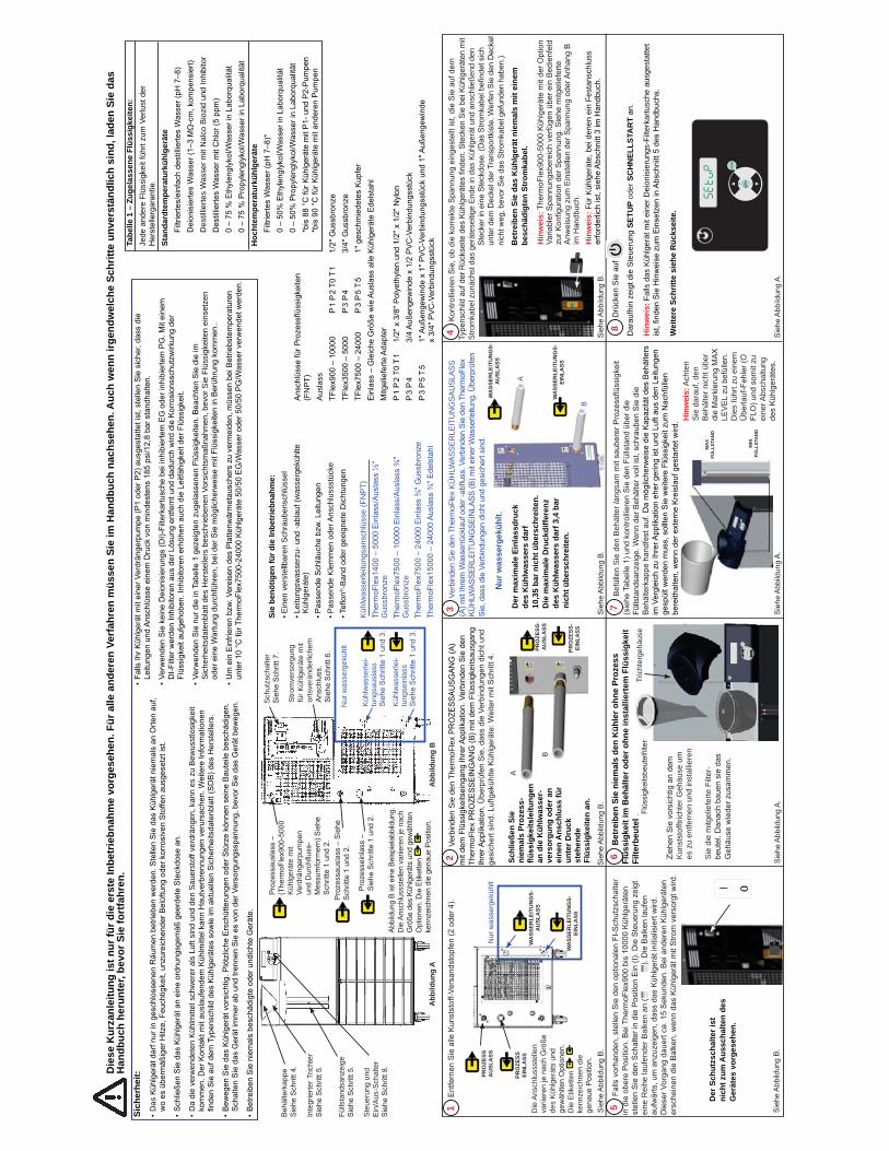
e 1
- App
rove
d Fl
uids
: Use of any other fluid will void the manufacturer’s
war
rant
y.
Filtered/single distilled water (pH 7-8)
Deionized water (1-3 MΩ-cm, compensated)
D
istil
led
wat
er w
ith N
alco
bio
cide
and
inhi
bito
r Distilled water with chlorine (5 ppm)
0 – 75% Laboratory Grade Ethylene Glycol/Water
0 – 75% Laboratory Grade Propylene Glycol/Water
Facility Water Connections (FNPT)
ThermoFlex1400 - 5000 Inlet/Outlet ½” cast bronze
ThermoFlex7500 - 10000 Inlet/Outlet ¾” cast bronze
ThermoFlex15000 - 24000 Inlet ¾” cast bronze
ThermoFlex15000 - 24000 Outlet ¾” stainless steel
Con
trolle
r See Step 8.
Pow
er B
utto
n See Step 8.
Inte
grat
ed F
unne
l See Step 5.
Leve
l Ind
icat
or
See Step 5.
Figu
re A
Res
ervo
ir C
ap
See
Ste
p 4.
Pro
cess
Out
let -
See Steps 1 and 2.
Pro
cess
Out
let -
(ThermoFlex900-
5000 chillers with
PD pumps and flow
trans
duce
rs)
See Steps 1 and 2.
Circ
uit P
rote
ctor
See Step 7.
Pow
er In
let f
or c
hille
rs
not h
ard-
wire
dS
ee S
tep
6.
Pro
cess
Inle
t -See Steps 1 and 2.
Faci
lity
Inle
tSee Steps 1 and 3.
Faci
lity
Out
let
See Steps 1 and 3.
Water-cooled only
Figu
re B
Figu
re B
is ty
pica
l.
Loca
tions
var
y w
ith c
hille
r si
ze a
nd s
elec
ted
optio
ns.
The
la
bels
iden
tify
the
exac
t loc
atio
n.
1 Remove all the plastic shipping plugs (2 or 4).
See
Fig
ure
B.
Water-cooled only
FAC
ILIT
YIN
LET
FAC
ILIT
YO
UTL
ET
PRO
CES
SIN
LET
PRO
CES
SO
UTL
ET
Loca
tions
var
y w
ith
chill
er s
ize
and
se-
lect
ed o
ptio
ns. T
he
la
bels
iden
tify
the
exac
t loc
atio
n.
Pro
cess
Flu
id C
onne
ctio
ns (F
NP
T)O
utle
t ThermoFlex900 - 10000 P 1 P 2 T0 T 1 1/2" cast bronze
ThermoFlex3500 - 5000 P 3 P 4 3/4" cast bronze
ThermoFlex7500 - 24000 P 3 P 5 T 5 1" wrought copper
Inle
t - S
ame
size
as
outle
t
all c
hille
rs s
tain
less
ste
elS
uppl
ied
Ada
pter
sP 1 P 2 T0 T 1 1/2" x 3/8'' Polyethylene and 1/2" x 1/2" Nylon
P 3 P 4
3/4 MPT x 1/2 barb PVC
P 3 P 5 T 5
1" MPT x 1" barb PVC and 1" MPT x 3/4" barb PVC
8 P
ress
.
The
cont
rolle
r will
dis
play
SEt
uP.
Not
e: If the chiller is equipped with a deionization filter cartridge refer to the
manual, Section 5, for installation.
Plea
se s
ee re
vers
e si
de fo
r add
ition
al s
teps
.
This
qui
ck s
tart
gui
de is
inte
nded
for i
nitia
l sta
rt u
p on
ly. F
or a
ll ot
her p
roce
dure
s yo
u m
ust r
efer
to th
e m
anua
l. A
lso,
if a
ny o
f the
se s
teps
are
not
cle
ar
dow
nloa
d th
e m
anua
l bef
ore
proc
eedi
ng.
Faci
lity
Wat
er M
axim
um
Inle
t Pre
ssur
e m
ust n
ot
exce
ed 1
50 P
SIG
. Fa
cilit
y W
ater
Max
imum
Pr
essu
re D
iffer
entia
l mus
t no
t exc
eed
50 P
SID
.
MIN
LEVE
L
MA
XLE
VEL
See
Fig
ure
A.
Not
e: B
e ca
refu
l not
to
fill the reservoir above
MAX LEVEL fill line.
This
will
resu
lt in
a u
nit
over flow error (O
FLO
) w
hich
will
cau
se th
e ch
iller
to s
hut d
own.
7 S
low
ly fill reservoir with clean process fluid (see Table 1), utilizing
sight tube for easy fluid level monitoring. When the reservoir is full re
-pl
ace
the
rese
rvoi
r cap
, han
d tig
ht. S
ince
the
rese
rvoi
r cap
acity
may
be
smal
l com
pare
d to
you
r app
licat
ion
and
air m
ay n
eed
to b
e pu
rged
from
the lines, have extra fluid on hand to keep the system topped off when
exte
rnal
circ
ulat
ion
is s
tarte
d. If the fluid level drops too low the chiller
will
shu
t dow
n to
pre
vent
the
pum
p fro
m ru
nnin
g dr
y . A
ckno
wle
dge
the
alar
m a
nd re
-sta
rt th
e pr
imin
g pr
oces
s.
See
Fig
ure
B.
The
circ
uit p
rote
ctor
is
not i
nten
ded
to a
ct a
s a
disc
onne
ctin
g m
eans
.
• N
ever
ope
rate
dam
aged
or l
eaki
ng e
quip
men
t.
• If your chiller is equipped with a positive displacement pump (P1 or P2), ensure your application plumbing
lines and fittings are rated to withstand a minimum of 185 psi.
• Do not use a Deionization (DI) filter cartridge with Inhibited EG or Inhibited PG. A DI filter will remove
inhibitors from the solution rendering the fluid ineffective against corrosion protection. Also, inhibitors
increase fluid conductivity.
• Use only the approved fluids shown in Table 1. Before using any fluid or performing maintenance where
contact with the fluid is likely, refer to the manufacturer’s MSDS for handling precautions.
• To prevent freezing/glazing of the plate exchanger, ThermoFlex7500-24000 chillers require the use of
50/50 EG/water or 50/50 PG/water below 10°C process temperature.
Nev
er c
onne
ct
lines
to y
our
faci
lity
wat
er
supp
ly o
r to
any
pres
suriz
ed
liqui
d so
urce
.
6 N
ever
ope
rate
the
chill
er w
ithou
t pro
cess
inst
alle
d.G
ently
pul
l up
on th
e pl
astic
fu
nnel
hou
sing
to re
mov
e it
and install the supplied filter
bag.
Rei
nsta
ll th
e ho
usin
g.
Rem
ove
the
rese
rvoi
r ca
p fro
m th
e ho
usin
g by
un
scre
win
g it
coun
terc
lock
-w
ise.
Flui
d Ba
g Fi
lter
Funn
el H
ousi
ng
Pre
ss
The
disp
lay
will
flas
h be
twee
n H
i t a
nd 4
2
If de
sire
d, u
se
to a
djus
t the
val
ue
Pre
ss
to s
eque
nce
to th
e ne
xt d
ispl
ay
Pre
ss
The
disp
lay
will
flas
h be
twee
n Lo
t an
d 3
If de
sire
d, u
se
to a
djus
t the
val
ue
Pre
ss
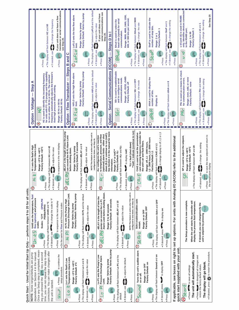
Lo t
sets
the
fluid
’s L
ow
Tem
pera
ture
Ala
rm L
imit.
Ran
ge: +
3°C
to +
42°C
Fact
ory
Def
ault:
3°C
Pre
ss
The
disp
lay
will
flas
h be
twee
n H
i P1
and
the
defa
ult
If de
sire
d, u
se
to a
djus
t the
val
ue
Pre
ss
Hi P
1 se
ts th
e Pu
mp’
s H
igh
Pres
sure
Dis
char
ge A
larm
Lim
it.
Ran
ge: V
arie
s by
pum
pFa
ctor
y D
efau
lt: V
arie
s by
pum
p
The
disp
lay
will
flas
h be
twee
n dE
LAY
and
0
If de
sire
d, u
se
to a
djus
t th
e va
lue
Pre
ss
dELA
Y is
the
leng
th o
f tim
e th
e pu
mp
can
exce
ed th
e H
i P1
Ala
rm L
imit
befo
re s
hutti
ng d
own.
Ran
ge: V
arie
s by
pum
pFa
ctor
y D
efau
lt: 0
sec
onds
Pre
ss
The
disp
lay
will
flas
h be
twee
n Lo
P1
and
the
defa
ult
If de
sire
d, u
se
to a
djus
t the
def
ault
P
ress
Lo P
1 se
ts th
e Pu
mp’
s Lo
w
Pres
sure
Dis
char
ge A
larm
Li
mit.
Ran
ge: V
arie
s by
pum
p Fa
ctor
y D
efau
lt: V
arie
s by
pum
p
dELA
Y is
the
leng
th o
f tim
e th
e pu
mp
can
exce
ed th
e Lo
P1
A
larm
Lim
it be
fore
shu
tting
dow
n.
Ran
ge: 0
to 3
0 se
cond
sFa
ctor
y D
efau
lt: 1
0 se
cond
s
The
disp
lay
will
flas
h be
twee
n dE
LAY
and
10
If de
sire
d, u
se
to a
djus
t the
val
ue
Pre
ss
Pre
ss
The
disp
lay
will
flas
h be
twee
n A
Lr a
nd fL
t
If de
sire
d, p
ress
to
dis
play
indC
Pre
ss
Turn
s th
e un
it’s
audi
ble
alar
m
on o
r off.
Ran
ge: o
n or
OFF
Fact
ory
Def
ault:
on
Pre
ss
The
disp
lay
will
flas
h be
twee
n So
und
and
on
If de
sire
d, p
ress
to
dis
play
OFF
Pre
ss
Pre
ss
The
disp
lay
will
flas
h be
twee
n St
Art
and
OFF
If de
sire
d, p
ress
to
dis
play
on
Pre
ss
StA
rt e
nabl
es/d
isab
les
auto
re
star
t.
Ran
ge: o
n or
OFF
Fact
ory
Def
ault:
OFF
Pre
ss
The
disp
lay
will
flas
h be
twee
n C
ArE
and
L1
If de
sire
d, u
se
to c
hang
e di
spla
y to
off,
L2
or L
3
Pre
ss
CA
rE is
use
d to
set
the
prev
enta
tive
care
cle
anin
g fr
eque
ncy
rem
inde
r for
th
e un
it’s
air a
nd fl
uid
filte
rs.
Ran
ge: o
ff, L
1 - 1
000
hour
s,
L2 -
2000
hou
rs, L
3 -3
000
hour
sFa
ctor
y D
efau
lt: L
1
Pre
ss
to s
ave
all s
ettin
gs
Pre
ss
to d
isre
gard
all
chan
ges
and
rest
ore
the
fact
ory
defa
ult v
alue
s.
If de
sire
d, p
ress
to
rest
art t
he p
roce
dure
.
The
Setu
p pr
oced
ure
is n
ow c
ompl
ete.
Whe
n th
e un
it st
arts
the
cont
rolle
r will
di
spla
y th
e pr
oces
s flu
id te
mpe
ratu
re.
If de
sire
d, y
ou c
an c
hang
e/ve
rify
the
unit’
s se
tpoi
nt b
y pr
essi
ng
.
SP is
use
d to
adj
ust t
he s
etpo
int.
Ran
ge: +
5°C
to +
40°C
Fa
ctor
y D
efau
lt: +
20°C
The
disp
lay
will
flas
h be
twee
n SP
and
20
If de
sire
d, u
se
to c
hang
e th
e se
tting
Pre
ss
to s
ave
the
new
set
poin
t and
retu
rn to
the
tem
pera
ture
dis
play
If ap
plic
able
, see
box
es o
n rig
ht to
set
up
optio
ns. F
or u
nits
with
Ana
log
I/O (A
CO
M) r
efer
to th
e ad
ditio
nal
quic
k st
art s
uppl
ied
with
you
r uni
t.
Qui
ck S
tart
- U
sed
for I
nitia
l Sta
rt U
p O
nly
— p
erfo
rm s
teps
9 to
20
for a
ll un
its.
** fL
t = fa
ult (
shut
dow
n)**
indC
= in
dica
te (c
ontin
ue to
run)
Hi t
set
s th
e flu
id’s
Hig
h Te
mpe
ratu
re A
larm
Lim
it.
Ran
ge: +
3°C
to +
42°C
Fact
ory
Def
ault:
+42
°C P
ress
Th
e di
spla
y w
ill fl
ash
betw
een
Uni
tS a
nd °C
If de
sire
d, u
se
to c
hang
e th
e sc
ale
to °
F
Pre
ss
to s
eque
nce
to th
e ne
xt d
ispl
ay
Do
the
sam
e fo
r Flo
w a
nd P
ress
ure
scal
es
Pre
ss
The
disp
lay
will
flas
h be
twee
n u
id a
nd 1
If de
sire
d, u
se
to c
hang
e th
e se
tting
Pre
ss
HiF
LO s
ets
the
high
flow
ala
rm
limit.
Ran
ge: V
arie
s by
pum
pFa
ctor
y D
efau
lt: V
arie
s by
pum
p
Pre
ss
The
disp
lay
will
flas
h be
twee
n H
iFLO
and
the
defa
ult
If de
sire
d, u
se
to a
djus
t the
val
ue
Pre
ss
Pre
ss
The
disp
lay
will
flas
h be
twee
n Lo
FLO
and
the
defa
ult
If de
sire
d, u
se
to a
djus
t the
val
ue
Pre
ss
LoFL
O s
ets
the
low
flow
ala
rm
limit.
Ran
ge: V
arie
s by
pum
pFa
ctor
y D
efau
lt: V
arie
s by
pum
p
Pre
ss
The
disp
lay
will
flas
h be
twee
n St
oP a
nd 1
If de
sire
d, u
se
to c
hang
e th
e se
tting
Pre
ss
StoP
is u
sed
to in
dica
te th
e nu
mbe
r of s
top
bits
.
Ran
ge: 2
or 1
Fa
ctor
y D
efau
lt: 1
u id
(uni
t id)
is u
sed
in R
S485
on
ly. I
dent
ifies
dev
ices
con
nect
ed
to th
e R
S485
por
t.
Ran
ge: 1
to 9
9 Fa
ctor
y D
efau
lt: 1
Pre
ss
The
disp
lay
will
flas
h be
twee
n SE
r and
OFF
If de
sire
d, u
se
to c
hang
e th
e m
ode
Pre
ss
SEr i
s us
ed to
ena
ble/
disa
ble
and
to c
onfig
ure
seria
l co
mm
unic
atio
ns m
ode.
Ran
ge: o
ff, rS
232,
rS48
5 Fa
ctor
y D
efau
lt: o
ff P
ress
Th
e di
spla
y w
ill fl
ash
betw
een
BA
ud a
nd 9
600
If de
sire
d, u
se
to c
hang
e th
e ra
te
Pre
ss
BA
ud is
use
d to
sel
ect t
he
baud
rate
(spe
ed) f
or s
eria
l co
mm
unic
atio
n.
Ran
ge: 9
600,
480
0, 2
400,
120
0,
600,
or 3
00 b
its p
er s
econ
d.
Pre
ss
The
disp
lay
will
flas
h be
twee
n dA
tA a
nd 8
Pre
ss
dAtA
is u
sed
to d
ispl
ay th
e nu
mbe
r of b
its.
Dis
play
: 8
Pre
ss
The
disp
lay
will
flas
h be
twee
n PA
r and
non
eIf
desi
red,
use
to
cha
nge
the
setti
ng
Pre
ss
PAr i
s us
ed a
s a
mea
ns to
che
ck
for c
omm
unic
atio
n er
rors
.
Ran
ge: e
ven,
odd
, or n
one
Fact
ory
Def
ault:
non
e
Opt
ion
- Flo
w T
rans
duce
r — S
teps
B a
nd C
If yo
ur u
nit d
oes
not h
ave
seria
l com
mun
icat
ions
see
St
ep 2
0.
See
Step
20.
Opt
ion
- Ser
ial C
omm
unic
atio
ns (D
CO
M) —
Ste
ps D
to I
Uni
tS a
re th
e te
mpe
ratu
re, fl
uid
flow
(opt
iona
l) an
d pr
essu
re
scal
es.
Scal
es:
°C/°F
GPM
/LPM
PSI/B
ar/K
PAS
Pre
ss
The
disp
lay
will
flas
h be
twee
n H
Z an
d 60
If ne
eded
, use
to
cha
nge
the
frequ
ency
Pre
ss
If yo
ur u
nit d
oes
not h
ave
a flo
w
tran
sduc
er o
r ser
ial c
omm
unic
atio
ns
see
Step
20.
Opt
ion
- Vol
tage
— S
tep
A
HZ
is u
sed
to id
entif
y th
e in
com
ing
freq
uenc
y fo
r uni
ts w
ith P
3 - P
5 pu
mps
and
the
capa
bilit
y to
run
on e
ither
50
Hz
or 6
0 H
z. T
he s
elec
ted
freq
uenc
y au
tom
atic
ally
adj
usts
the
firm
war
e's
fixed
hig
h pr
essu
re d
efau
lt se
tting
.
Ran
ge: 5
0 H
z or
60
Hz
Fact
ory
Def
ault:
60
Hz
I
Pre
ss
to c
ontin
ue th
e
s
etup
pro
cedu
re.
NO
TE: S
ome
rang
es/d
efau
lts a
re p
ump
depe
nden
t, se
e S
ectio
n 4
in th
e m
anua
l. O
nce
any
Set
up s
tep
is c
ompl
eted
, mea
n-in
g yo
u pr
esse
d th
e
key
a s
econ
d tim
e, y
ou c
an n
ot re
peat
the
step
to m
ake
corr
ectio
ns. Y
ou c
an m
ake
chan
ges
afte
r th
e un
it is
sta
rted.
NO
TE T
his
feat
ure
is a
ctiv
e on
ly if
the
unit
is
confi
gure
d to
shu
t dow
n, s
ee S
tep
16.
NO
TE T
his
feat
ure
is a
ctiv
e on
ly if
the
unit
is
confi
gure
d to
shu
t dow
n, s
ee S
tep
16.
ALr
con
figur
es th
e un
it’s
reac
tion
to te
mpe
ratu
re, p
ress
ure,
and
flow
(o
ptio
nal)
alar
m li
mits
- ei
ther
shu
t do
wn
(fLt)
or c
ontin
ue to
run
(indC
). Se
e Se
ctio
n 4
in th
e m
anua
l for
mor
e in
form
atio
n.R
ange
: fLt
* or i
ndC
**Fa
ctor
y D
efau
lt: fL
t
The
unit
will
aut
omat
ical
ly s
tart
.
The
disp
lay
will
go
blan
k.
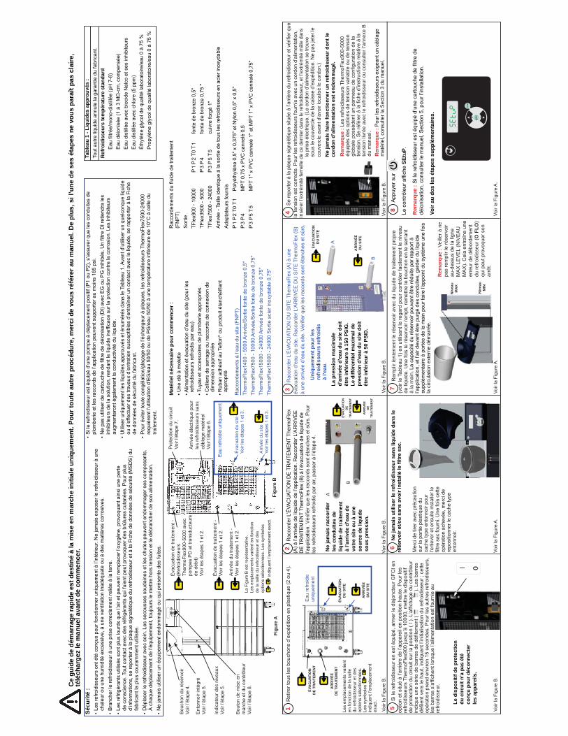
3 R
acco
rder
L’É
VAC
UAT
ION
DU
SIT
E T
herm
oFle
x (A
) à u
ne
évac
uatio
n d’
eau
du s
ite. R
acco
rder
L’A
RR
IVÉ
E D
U S
ITE
The
rmoF
lex
(B)
à un
e ar
rivée
d’eau du site. Vérifier que les raccords sont étanches et sûrs.
Mat
érie
l néc
essa
ire p
our c
omm
ence
r :• Une clé à molette
• Alimentation et évacuation d’eau du site (pour les
refroidisseurs refroidis par eau)
• Tuyau et accessoires de plomberie appropriés
• Colliers de serrage ou raccords de connexion de
dimension appropriée
• Ruban adhésif au Teflon
® ou produit étanchéifiant
approprié
Sécu
rité
:• Les refroidisseurs ont été conçus pour fonctionner uniquement à l’intérieur. Ne jamais exposer le refroidisseur à une
chaleur ou une humidité excessive, à une ventilation inadéquate ou à des matières corrosives.
• Brancher le refroidisseur à une prise correctement reliée à la terre.
• Les réfrigérants utilisés sont plus lourds que l’air et peuvent remplacer l’oxygène, provoquant ainsi une perte
de conscience. Tout contact avec des réfrigérants qui fuient peut provoquer des brûlures cutanées. Pour plus
d’informations, se reporter à la plaque signalétique du refroidisseur et à la Fiche de données de sécurité (MSDS) du
fabricant la plus couramment utilisée.
• Déplacer le refroidisseur avec soin. Les secousses soudaines et les chutes peuvent endommager ses composants.
À chaque déplacement de l’équipement, toujours le mettre hors tension et le débrancher de son alimentation.
• Ne jamais utiliser un équipement endommagé ou qui présente des fuites.
Uni
quem
ent p
our l
es
refr
oidi
sseu
rs re
froi
dis
à l’e
au.
Voir la Figure B.
Voir la Figure B.
Voir la Figure A.
Voir la Figure A.
B
A
2 R
acco
rder
L’ÉVACUATION DE TRAITEMENT
Ther
moF
lex
(A) à l’arrivée de liquide de l’application. Raccorder L
’AR
RIV
ÉE
DE TRAITEMENT ThermoFlex (B) à l’évacuation de liquide de
l’application. Vérifier que les raccords sont étanches et sûrs. Pour
les refroidisseurs refroidis par air, passer à l’étape 4.
B
A
AR
RIV
ÉED
E TR
AIT
EMEN
T
ÉVA
CU
ATIO
N
DE
TRA
ITEM
ENT
AR
RIV
ÉED
U S
ITE
ÉVA
CU
ATIO
ND
U S
ITE
Voir la Figure B.
5 Si le refroidisseur en est équipé, armer le disjoncteur GFCI en
option et situé à l’arrière de l’appareil en position haute. Pour les
refroidisseurs ThermoFlex900 jusqu’à 10000, mettre le dispositif
de protection du circuit sur la position ( I ). L’affichage du contrôleur
indique une série de barres de défilement (
). Les barres
défilent vers le haut, indiquant l’initialisation du refroidisseur ; cette
opération prend environ 15 secondes. Pour les autres refroidisseurs,
les barres s’affichent lorsque l’alimentation est fournie au
refro
idis
seur
.
4 Se reporter à la plaque signalétique située à l’arrière du refroidisseur et vérifier que
la tension est correcte. Pour les refroidisseurs fournis avec un cordon d’alimentation,
insé
rer l
’ext
rém
ité fe
mel
le d
e ce
der
nier
dan
s le
refro
idis
seur
, et l
’ext
rém
ité m
âle
dans
la prise électrique. (Le cordon d’alimentation se trouve
sous le couvercle de la caisse d’expédition. Ne pas jeter le
couv
ercl
e av
ant d
’avo
ir lo
calis
é le
cor
don.
) N
e ja
mai
s fa
ire fo
nctio
nner
un
refr
oidi
sseu
r don
t le
cord
on d
’alim
enta
tion
est e
ndom
mag
é.
Rem
arqu
e : Les refroidisseurs ThermoFlex900-5000
équipés des options de tension variable ou de tension
globale possèdent un panneau de configuration de la
tension. Se référer à la fiche d’instructions relative à la
tens
ion
livré
e av
ec le
refro
idis
seur
ou
cons
ulte
r l’a
nnex
e B
du
man
uel.
Rem
arqu
e : Pour les refroidisseurs exigeant un câblage
mat
érie
l, co
nsul
ter l
a S
ectio
n 3
du m
anue
l.
+ -
ente
r
mode
Tabl
eau
1 - L
iqui
des
appr
ouvé
s :
Tout autre liquide annule la garantie du fabricant.
Ref
roid
isse
urs
tem
péra
ture
sta
ndar
d Eau filtrée/mono-distillée (pH 7-8)
Eau déionisée (1 à 3 MΩ-cm, compensée)
Eau distillée avec biocide Nalco et ses inhibiteurs
Eau distillée avec chlore (5 ppm)
Éthylène glycol de qualité laboratoire/eau 0 à 75 %
Propylène glycol de qualité laboratoire/eau 0 à 75 %
Raccordements à l’eau du site (FNPT)
ThermoFlex1400 - 5000 Arrivée/Sortie fonte de bronze 0,5"
ThermoFlex7500 - 10000 Arrivée/Sortie fonte de bronze 0,75"
ThermoFlex15000 - 24000 Arrivée fonte de bronze 0,75"
ThermoFlex15000 - 24000 Sortie acier inoxydable 0,75"
Bou
ton
de m
ise
en
marche et du contrôleur
Voir l’étape 8.
Entonnoir intégré
Voir l’étape 5.
Indi
cate
ur d
es n
ivea
ux
Voir l’étape 5.
Figu
re A
Bou
chon
du
rése
rvoi
r Voir l’étape 4.
Éva
cuat
ion
de tr
aite
men
t -
Voir les étapes 1 et 2.
Éva
cuat
ion
de tr
aite
men
t -
(Ref
roid
isse
urs
ThermoFlex900-5000 avec
pompes PD et transducteurs
de débit)
Voir les étapes 1 et 2.
Protection du circuit
Voir l’étape 7.
Arrivée électrique pour
les
refro
idis
seur
s sa
ns
câblage matériel
Voir l’étape 6.
Arr
ivée
du
traite
men
t -Voir les étapes 1 et 2.
V
Arr
ivée
du
site
Voir les étapes 1 et 3.
Éva
cuat
ion
du s
ite
Voir les étapes 1 et 3.
Eau refroidie uniquement
Figu
re B
La Figure B est représentative.
Les emplacements varient en fonction
de la
taill
e du
refro
idis
seur
et d
es
options sélectionnées. Les symboles
indiquent l’emplacement exact.
1 Retirer tous les bouchons d’expédition en plastique (2 ou 4).
Voir la Figure B.
Eau
refro
idie
uniquement
AR
RIV
ÉED
U S
ITE
ÉVA
CU
ATIO
ND
U S
ITE
AR
RIV
ÉED
E TR
AIT
EMEN
T
ÉVA
CU
ATIO
ND
E TR
AIT
EMEN
T
Les emplacements varient
en fo
nctio
n de
la ta
ille
du re
froid
isse
ur e
t des
options sélectionnées.
Les symboles
indiquent l’emplacement
exac
t.
Raccordements du fluide de traitement
(FNPT)
Sor
tie
TFlex900 - 10000
P 1 P 2 T0 T 1 fonte de bronze 0,5"
TFlex3500 - 5000
P 3 P 4
fonte de bronze 0,75 "
TFlex7500 - 24000
P 3 P 5 T 5
cuivre forgé 1"
Arrivée - Taille identique à la sortie de tous les refroidisseurs en acier inoxydable
Adaptateurs fournis
P 1 P 2 T0 T 1 Polyéthylène 0,5" x 0,375" et Nylon 0,5" x 0,5"
P 3 P 4
MPT 0,75 x PVC cannelé 0,5
P 3 P 5 T 5
MPT 1" x PVC cannelé 1" et MPT 1" x PVC cannelé 0,75"
8 Appuyer sur
.
Le contrôleur affiche
SEtu
P.
Rem
arqu
e : Si le refroidisseur est équipé d’une cartouche de filtre de
déionisation, consulter le manuel, Section 5, pour l’installation.
Voir
au d
os le
s ét
apes
sup
plém
enta
ires.
Ce
guid
e de
dém
arra
ge ra
pide
est
des
tiné
à la
mis
e en
mar
che
initi
ale
uniq
uem
ent.
Pour
tout
e au
tre
proc
édur
e, m
erci
de
vous
réfé
rer a
u m
anue
l. D
e pl
us, s
i l’u
ne d
e se
s ét
apes
ne
vous
par
aît p
as c
laire
, té
léch
arge
z le
man
uel a
vant
de
com
men
cer.
La p
ress
ion
max
imal
e d’
arriv
ée d
’eau
du
site
doi
t êt
re in
férie
ure
à 15
0 PS
IG.
Le d
iffér
entie
l max
imal
de
pres
sion
d’e
au d
u si
te d
oit
être
infé
rieur
à 5
0 PS
ID.
Niv
eau
MIN
Niv
eau
MA
X
Voir la Figure A.
Rem
arqu
e : V
eille
r à n
e pas remplir le réservoir
au-dessus de la ligne
MAX LEVEL (NIVEAU
MAX). Cela entraîne une
erreur de débordement
du re
froid
isse
ur (O
FLO
) qui peut provoquer son
arrê
t.
7 Remplir
lent
emen
t le réservoir avec du liquide de traitement propre
(voir le Tableau 1) en utilisant le regard pour contrôler facilement le niveau
de liquide. Une fois le réservoir rempli, remettre le bouchon en le serrant
à la
mai
n. La capacité du réservoir pouvant être réduite par rapport à
l’application, et l’air devant être purgé des conduites, garder du liquide
supplémentaire à portée de la main pour faire l'appoint du système une fois
la c
ircul
atio
n ex
tern
e dé
mar
rée.
É
Voir la Figure B.
Le d
ispo
sitif
de
prot
ectio
n du
circ
uit n
’a p
as é
té
conç
u po
ur d
écon
nect
er
les
appa
reils
.
• Si le refroidisseur est équipé d’une pompe à déplacement positif (P1 ou P2), s’assurer que les conduites de
plomberie et les raccords de l’application peuvent supporter au moins 185 psi.
• Ne pas utiliser de cartouche de filtre de déionisation (DI) avec EG ou PG inihibés. Un filtre DI retiendra les
inhibiteurs de la solution, rendant le liquide inefficace sur la protection contre la corrosion. Les inhibiteurs
augmenteront également la conductivité du liquide.
• Utiliser uniquement les liquides approuvés et énumérés dans le Tableau 1. Avant d’utiliser un quelconque liquide
ou d’effectuer des travaux d’entretien susceptibles d’entraîner un contact avec le liquide, se rapporter à la Fiche
de données de sécurité du fabricant.
• Pour éviter toute congélation/glaçage de l’échangeur à plaques, les refroidisseurs ThermoFlex7500-24000
requièrent l’utilisation d’EG/eau 50/50 ou de PG/eau 50/50 à une température inférieure de 10°C à celle du
traite
men
t.
Ne
jam
ais
racc
orde
r le
s co
ndui
tes
de
liqui
de d
e tr
aite
men
t à
l’arr
ivée
d’e
au d
e vo
tre
site
ou
à un
e so
urce
de
liqui
de
sous
pre
ssio
n.
6 N
e ja
mai
s ut
ilise
r le
refr
oidi
sseu
r san
s liq
uide
dan
s le
Merci de tirer avec précaution
sur la partie plastique du
cache type entonnoir pour
l’enl
ever
et e
nsui
te in
stal
ler l
e filtre sac fourni. Une fois cette
opération achevée, merci de
repositionner le cache type
ento
nnoi
r.
• Appuyez sur
• L’affichage clignote en alternant H
i t et 4
2
• Au besoin, utilisez
pour modifier la valeur
• Appuyez sur
pour passer à l’affichage suivant
• Appuyez sur
• L’affichage clignote en alternant L
o t et 3
• Au besoin, utilisez
pour modifier la valeur
• Appuyez sur
Lo t
règl
e la
lim
ite d
’ala
rme
de b
asse
te
mpé
ratu
re d
u liq
uide
.Pl
age
: +3°
C à
+42
°CR
égla
ge d
’usi
ne p
ar d
éfau
t : 3
°C
• Appuyez sur
• L’affichage clignote en alternant H
i P1 et la valeur par défaut
• Au besoin, utilisez
pour modifier la valeur
• Appuyez sur
Hi P
1 rè
gle
la li
mite
d’a
larm
e de
dé
char
ge h
aute
pre
ssio
n de
la p
ompe
.Pl
age
: Var
ie e
n fo
nctio
n de
la p
ompe
Rég
lage
d’u
sine
par
déf
aut :
Var
ie e
n fo
nctio
n de
la p
ompe
• L’affichage clignote en alternant d
ELAY
et 0
• Au besoin, utilisez
pour modifier la valeur
• Appuyez sur
dELA
Y re
prés
ente
la d
urée
pen
dant
la
quel
le la
pom
pe p
eut d
épas
ser l
a va
leur
d’
alar
me
Hi P
1 av
ant l
’arr
êt.
Plag
e : V
arie
en
fonc
tion
de la
pom
peR
égla
ge d
’usi
ne p
ar d
éfau
t : 0
sec
onde
s
• Appuyez sur
• L’affichage clignote en alternant L
o P1 et la valeur par défaut
• Au besoin, utilisez
pour ajuster la valeur par défaut
• Appuyez sur
Lo P
1 rè
gle
la li
mite
d’a
larm
e de
dé
char
ge b
asse
pre
ssio
n de
la p
ompe
.Pl
age
: Var
ie e
n fo
nctio
n de
la p
ompe
Rég
lage
d’u
sine
par
déf
aut :
Var
ie
en fo
nctio
n de
la p
ompe
dELA
Y re
prés
ente
la d
urée
pen
dant
la
quel
le la
pom
pe p
eut d
épas
ser l
a va
leur
Lo
P1
Lim
ite d
’ala
rme
avan
t arr
êt.
Plag
e : 0
à 3
0 se
cond
esR
égla
ge d
’usi
ne p
ar d
éfau
t :
10 s
econ
des
• L’affichage clignote en alternant d
ELAY
et 1
0• Au besoin, utilisez
pour modifier la valeur
• Appuyez sur
• Appuyez sur
• L’affichage clignote en alternant A
Lr et f
Lt• Au besoin, appuyez sur
pour afficher in
dC
• Appuyez sur
y
Act
ive
ou d
ésac
tive
le s
igna
l so
nore
d’a
larm
e de
l’ap
pare
il.Pl
age
: on
(mar
che)
ou
OFF
(AR
RÊT
)R
égla
ge d
’usi
ne p
ar d
éfau
t : o
n (m
arch
e)
• Appuyez sur
(m
• L’affichage clignote en alternant S
ound
et o
n (m
arch
e)• Au besoin, appuyez sur
pour afficher O
FF
(AR
RÊT
)
• Appuyez sur
• Appuyez sur
• L’affichage clignote en alternant S
tArt
et O
FF (A
RR
ÊT)
• Au besoin, appuyez sur
pour afficher o
n (m
arch
e)
• Appuyez sur
StA
rt a
ctiv
e/dé
sact
ive
le
redé
mar
rage
aut
omat
ique
.Pl
age
: on
(mar
che)
ou
OFF
(AR
RÊT
)R
égla
ge d
’usi
ne p
ar d
éfau
t : O
FF
(AR
RÊT
)
• Appuyez sur
• L’affichage clignote en alternant C
ArE
et L
1
• Au besoin, utilisez
pour modifier l’affichage sur arrêt, L2 ou L3
• Appuyez sur
et à
liqu
ide
de l’
appa
reil.
Pl
age
: off,
L1
- 100
0 he
ures
, L2
- 20
00 h
eure
s, L
3 -3
000
heur
esR
égla
ge d
’usi
ne p
ar d
éfau
t : L
1
• Appuyez sur
pour enregistrer t
ous les réglages
L’
appa
reil
dém
arre
aut
omat
ique
men
t.• Appuyez sur
pour ignorer to
utes les
modifications et rétablir les valeurs par défaut d’usine.
L’affiche est vide.
Appuyez sur
pour recommencer la procédure
term
inée
.
tem
péra
ture
du
liqui
de d
e l’a
pplic
atio
n.
.
SP s
ert à
régl
er la
val
eur d
e co
nsig
ne.
Plag
e : +
5°C
à +
40°C
Rég
lage
d’u
sine
par
déf
aut :
+20
°C
• L’affichage clignote en alternant S
P et 2
0
• Au besoin, utilisez
pour modifier le réglage
• Appuyez sur
pour enregistrer la nouvelle valeur de
consigne et revenir à l’affichage de la température
(AC
OM
) con
sulte
z la
doc
umen
tatio
n de
dém
arra
ge ra
pide
sup
plém
enta
ire fo
urni
e av
ec l’
appa
reil.
Dém
arra
ge ra
pide
- N
e se
rt q
ue p
our l
e pr
emie
r dém
arra
ge -
effe
ctue
r les
éta
pes
9 à
20 p
our t
oute
s le
s un
ités.
** fL
t = e
rreu
r (ar
rêt)
** in
dC =
indi
quer
(pou
rsui
te d
e l’e
xécu
tion)
Hi t
règl
e la
lim
ite d
’ala
rme
de h
aute
te
mpé
ratu
re d
u liq
uide
.Pl
age
: +3°
C à
+42
°CR
égla
ge d
’usi
ne p
ar d
éfau
t : +
42°C
• Appuyez sur
• L’affichage clignote en alternant U
nits
(uni
tés)et °C
• Au besoin, utilisez
pour passer à un affichage en °F
• Appuyez sur
pour passer à l’affichage suivant
• Procédez de la même façon pour les échelles de d
ébit et de pression
• Appuyez sur
• L’affichage clignote en alternant u
id et 1
• Au besoin, utilisez
pour modifier le réglage
• Appuyez sur
débi
t éle
vé.
Plag
e : V
arie
en
fonc
tion
de la
pom
peR
égla
ge d
’usi
ne p
ar d
éfau
t : V
arie
en
fonc
tion
de la
pom
pe
• Appuyez sur
f
• L’affichage clignote en alternantH
iFLO et la valeur par défaut
• Au besoin, utilisez
pour modifier la valeur
• Appuyez sur
• Appuyez sur
• L’affichage clignote en alternantL
oFLO et la valeur par défaut
• Au besoin, utilisez
pour modifier la valeur
• Appuyez sur
faib
le d
ébit.
Pl
age
: Var
ie e
n fo
nctio
n de
la p
ompe
Rég
lage
d’u
sine
par
déf
aut :
Var
ie e
n fo
nctio
n de
la p
ompe
• Appuyez sur
• L’affichage clignote en alternant S
toP et 1
• Au besoin, utilisez
pour modifier le réglage
• Appuyez sur
StoP
ser
t à in
diqu
er le
nom
bre
de b
its
d’ar
rêt.
Plag
e : 2
ou
1R
égla
ge d
’usi
ne p
ar d
éfau
t : 1
appa
reils
racc
ordé
s au
por
t RS4
85.
Plag
e : 1
à 9
9R
égla
ge d
’usi
ne p
ar d
éfau
t : 1
• Appuyez sur
• L’affichage clignote en alternant S
Er et O
FF (A
RR
ÊT)
• Au besoin, utilisez
pour modifier le mode
• Appuyez sur
SEr s
ert à
act
iver
/dés
activ
er
com
mun
icat
ions
sér
ie.
Plag
e : o
ff, rS
232,
rS48
5R
égla
ge d
’usi
ne p
ar d
éfau
t : o
ff
• Appuyez sur
• L’affichage clignote en alternant B
Aud
et 9
600
• Au besoin, utilisez
pour modifier le débit
• Appuyez sur
BA
ud s
ert à
sél
ectio
nner
le d
ébit
(la
vite
sse)
de
com
mun
icat
ion
série
.
Plag
e : 9
600,
480
0, 2
400,
120
0,
600
ou 3
00 b
its p
ar s
econ
de.
Rég
lage
d’u
sine
par
déf
aut :
960
0
• Appuyez sur
• L’affichage clignote en alternant d
AtA
et 8
• Appuyez sur
dAtA
ser
t à in
diqu
er le
nom
bre
de b
its.
• Appuyez sur
• L’affichage clignote en alternant P
ar et n
one
(auc
un)
• Au besoin, utilisez
pour modifier le réglage
• Appuyez sur
erre
urs
de c
omm
unic
atio
n.
Plag
e : p
air,
impa
ir, o
u au
cun
Rég
lage
d’u
sine
par
déf
aut :
auc
un
Opt
ion
- Tra
nsdu
cteu
r de
débi
t - é
tape
s B
et C
Si l’
unité
ne
com
port
e pa
s de
com
-m
unic
atio
ns s
érie
, voi
r l’é
tape
20.
Voir
l’éta
pe 2
0.
Uni
tS re
prés
ente
les
éche
lles
de
tem
péra
ture
, de
débi
t de
liqui
de (e
n op
tion)
et d
e pr
essi
on.
Éche
lles
: °C
/°F
GPM
/LPM
• Appuyez sur
• L’affichage clignote en alternant H
Z et 6
0• Au besoin, utilisez
pour modifier la fréquence
• Appuyez sur
Opt
ion
- Ten
sion
glo
bale
- Ét
ape
A
unité
s de
tens
ion
glob
ales
. La
fréq
uenc
e sé
lect
ionn
ée
ajus
te a
utom
atiq
uem
ent l
e ré
glag
e de
hau
te p
ress
ion
par d
éfau
t d
u m
icro
prog
ram
me.
Plag
e : 5
0 ou
60
Hz
Par d
éfau
t : 6
0 H
z
I
Appuyez sur
pour poursuivre
la procédure de l’étape.
REM
ARQU
E : Certaines plages/valeurs par défaut
dépendent de la pompe, voir la Section 4 du manuel.
Une fois l’étape de configuration terminée, c’est-à-dire
après avoir appuyé sur la touche
une deuxiè-
me fois, il devient impossible de recommencer l’étape
pour effectuer des corrections. Vous
pouv
ez faire des
modifications après le démarrage de l’appareil.
REM
AR
QU
E C
ette
fonc
tion
n’es
t act
ive
que
si
REM
AR
QU
E C
ette
fonc
tion
n’es
t act
ive
que
si
limite
s d’
alar
me
de te
mpé
ratu
re, d
e pr
essi
on,
et d
e dé
bit (
en o
ptio
n) -
ferm
e (fL
t) ou
con
tinue
l’e
xécu
tion
(indC
). Vo
ir la
sec
tion
4 du
man
uel
pour
des
info
rmat
ions
plu
s dé
taill
ées.
Plag
e : f
Lt* o
u in
dC**
Rég
lage
d’u
sine
par
déf
aut :
fLt
Si v
otre
app
arei
l n’e
st p
as é
quip
é d’
un tr
ansd
ucte
ur d
e dé
bit o
u de
com
mun
icat
ions
sér
ie, v
oir l
’éta
pe 2
0.
3 V
erbi
nden
Sie
den
The
rmoF
lex
KÜH
LWAS
SER
LEIT
UN
GSA
USL
ASS
(A) mit Ihrem Wasserrücklauf oder -abfluss. Verbinden Sie den ThermoFlex
KÜHLWASSERLEITUNGSEINLASS (B) mit einer Wasserleitung. Überprüfen
Sie, dass die Verbindungen dicht und gesichert sind.
Sie
benö
tigen
für d
ie In
betr
iebn
ahm
e:E
inen
ver
stel
lbar
en S
chra
uben
schl
üsse
lLe
itung
swas
serz
u- u
nd -a
blau
f (w
asse
rgek
ühlte
K
ühlg
erät
e)Passende Schläuche bzw. Leitungen
Pas
send
e K
lem
men
ode
r Ans
chlu
ssst
ücke
Teflon®
-Ban
d od
er g
eeig
nete
Dic
htun
gen
Sich
erhe
it:
• D
as Kühlgerät darf nur in geschlossenen Räumen betrieben werden. Stellen Sie das Kühlgerät niemals an Orten auf,
wo es übermäßiger Hitze, Feuchtigkeit, unzureichender Belüftung oder korrosiven Stoffen ausgesetzt ist.
• Schließen Sie das Kühlgerät an eine ordnungsgemäß geerdete Steckdose an.
• D
a di
e ve
rwen
dete
n K
ühlm
ittel
sch
wer
er a
ls L
uft s
ind
und
den
Sau
erst
off v
erdr
änge
n, k
ann
es z
u B
ewus
stlo
sigk
eit
kommen. Der Kontakt mit auslaufendem Kühlmittel kann Hautverbrennungen verursachen. Weitere Informationen
finden Sie auf dem Typenschild des Kühlgerätes sowie im aktuellen Sicherheitsdatenblatt (SDB) des Herstellers.
• Bewegen Sie das Kühlgerät vorsichtig. Plötzliche Erschütterungen oder Stürze können seine Bauteile beschädigen.
Schalten Sie das Gerät immer ab und trennen Sie es von der Versorgungsspannung, bevor Sie das Gerät bewegen.
• Betreiben Sie niemals beschädigte oder undichte Geräte.
Nur
was
serg
eküh
lt.
Siehe Abbildung B.
Siehe Abbildung B.
Siehe Abbildung A.
Siehe Abbildung A.
B
A
2 V
erbi
nden
Sie
den
The
rmoF
lex PROZESSAUSGANG
(A)
mit dem Flüssigkeitseingang Ihrer Applikation. Verbinden Sie den
Ther
moF
lex PROZESSEINGANG (B
) mit
dem
Flü
ssig
keits
ausg
ang
Ihrer Applikation. Überprüfen Sie, dass die Verbindungen dicht und
gesichert sind. Luftgekühlte Kühlgeräte: Weiter mit Schritt 4.
B
A
PRO
ZESS
-EI
NLA
SS
PRO
ZESS
-A
USL
ASS
WA
SSER
LEIT
UN
GS-
EIN
LASS
WA
SSER
LEIT
UN
GS-
AU
SLA
SS
Siehe Abbildung B.
5 Falls vorhanden, stellen Sie den optionalen FI-Schutzschalter
in die obere Position. Bei ThermoFlex900 bis 10000 Kühlgeräten
stellen Sie den Schalter in die Position Ein (I). Die Steuerung zeigt
eine
Rei
he la
ufen
der B
alke
n an
(). Die Balken laufen
aufwärts, um anzuzeigen, dass das Kühlgerät initialisiert wird.
Dieser Vorgang dauert ca. 15 Sekunden. Bei anderen Kühlgeräten
erscheinen die Balken, wenn das Kühlgerät mit Strom versorgt wird.
4 Kontrollieren Sie, ob die korrekte Spannung eingestellt ist, die Sie auf dem
Typenschild auf der Rückseite des Kühlgerätes finden. Stecken Sie bei Kühlgeräten mit
Stro
mka
bel z
unäc
hst d
as g
erät
esei
tige
Ende
in d
as K
ühlg
erät
und
ans
chlie
ßend
den
Stecker in eine Steckdose. (Das Stromkabel befindet sich
unter dem Deckel der Transportkiste. Werfen Sie den Deckel
nicht weg, bevor Sie das Stromkabel gefunden haben.)
Bet
reib
en S
ie d
as K
ühlg
erät
nie
mal
s m
it ei
nem
be
schä
digt
en S
trom
kabe
l.
Hin
wei
s: ThermoFlex900-5000 Kühlgeräte mit der Option
V ariabler Spannungsbereich verfügen über ein Bedienfeld
zur Konfiguration der Spannung. Siehe mitgelieferte
Anweisung zum Einstellen der Spannung oder Anhang B
im Handbuch.
Hin
wei
s: F
ür K
ühlg
erät
e, b
ei d
enen
ein
Fes
tans
chlu
ss
erforderlich ist, siehe Abschnitt 3 im Handbuch.
+ -
ente
r
mode
Tabe
lle 1
– Z
ugel
asse
ne F
lüss
igke
iten:
Je
de a
nder
e Fl
üssi
gkei
t füh
rt zu
m V
erlu
st d
er
Herstellergarantie.
Stan
dard
tem
pera
turk
ühlg
erät
e Filtriertes/einfach destilliertes Wasser (pH 7–8)
Deionisiertes Wasser (1–3 MΩ-cm, kompensiert)
D
estil
lierte
s W
asse
r mit
Nal
co B
iozi
d un
d In
hibi
tor
Destilliertes Wasser mit Chlor (5 ppm)
0 – 75 % Ethylenglykol/Wasser in Laborqualität
0 – 75 % Propylenglykol/Wasser in Laborqualität
Hoc
htem
pera
turk
ühlg
erät
e Filtriertes Wasser (pH 7–8)*
0 – 50% Ethylenglykol/Wasser in Laborqualität
0 – 50% Propylenglykol/Wasser in Laborqualität
*bis 88 °C für Kühlgeräte mit P1- und P2-Pumpen
*bis 90 °C für Kühlgeräte mit anderen Pumpen
Küh
lwas
serle
itung
sans
chlü
sse
(FN
PT)
ThermoFlex1400 – 5000 Einlass/Auslass ½"
Gus
sbro
nze
ThermoFlex7500 – 10000 Einlass/Auslass ¾"
Gus
sbro
nze
ThermoFlex7500 – 24000 Einlass ¾" Gussbronze
ThermoFlex15000 – 24000 Auslass ¾" Edelstahl
Ste
ueru
ng u
nd
Ein
/Aus
-Sch
alte
rSiehe Schritt 8.
Inte
grie
rter T
richt
er
Siehe Schritt 5.
Fülls
tand
sanz
eige
Siehe Schritt 5.
Abb
ildun
g A
Behälterkappe
Siehe Schritt 4.
Prozessauslass – Siehe
Schritte 1 und 2.
Prozessauslass –
(ThermoFlex900-5000
Küh
lger
äte
mit
Verdrängerpumpen
und Durchfluss-
Messumformern) Siehe
Schritte 1 und 2.
Sch
utzs
chal
ter
Siehe Schritt 7.
Stro
mve
rsor
gung
fü
r Küh
lger
äte
mit
orts
verä
nder
liche
m
Anschluss.
Siehe Schritt 6.
Prozesseinlass –
Siehe Schritte 1 und 2.
Küh
lwas
serle
i-tu
ngse
inla
ssSiehe Schritte 1 und 3.
Küh
lwas
serle
i-tu
ngsa
usla
ss
Siehe Schritte 1 und 3.
Nur
was
serg
eküh
lt
Abb
ildun
g B
Abbildung B ist eine Beispielabbildung.
Die
Ans
chlu
ssst
elle
n va
riier
en je
nac
h Größe des Kühlgeräts und gewählten
Optionen. Die Etiketten
g g
kennzeichnen die genaue Position.
1 Entfernen Sie alle Kunststoff-Versandstopfen (2 oder 4).
Siehe Abbildung B.
Nur
was
serg
eküh
lt
WA
SSER
LEIT
UN
GS-
EIN
LASS
WA
SSER
LEIT
UN
GS-
AU
SLA
SS
PRO
ZESS
EIN
LASS
PRO
ZESS
AU
SLA
SS
Die
Ans
chlu
ssst
elle
n variieren je nach Größe
des
Küh
lger
äts
und
gewählten Optionen.
Die
Etik
ette
n
ke
nnze
ichn
en d
ie
genaue Position.
Anschlüsse für Prozessflüssigkeiten
(F
NP
T)A
usla
ss
TFlex900 – 10000
P 1 P 2 T0 T 1 1/2" Gussbronze
TFlex3500 – 5000
P 3 P 4
3/4" Gussbronze
TFlex7500 – 24000
P 3 P 5 T 5
1" geschmiedetes Kupfer
Einlass – Gleiche Größe wie Auslass alle Kühlgeräte Edelstahl
Mitgelieferte Adapter
P 1 P 2 T0 T 1 1/2" x 3/8'' Polyethylen und 1/2" x 1/2" Nylon
P 3 P 4
3/4 Außengewinde x 1/2 PVC-Verbindungsstück
P 3 P 5 T 5
1" Außengewinde x 1" PVC-Verbindungsstück und 1" Außengewinde
x 3/4" PVC-Verbindungsstück
8 D
rück
en S
ie a
uf
.
Dar
aufh
in z
eigt
die
Ste
ueru
ng S
ETU
P od
er S
CH
NEL
LSTA
RT an.
Hin
wei
s: F
alls
das
Küh
lger
ät m
it ei
ner D
eion
isie
rung
s-Fi
lterk
artu
sche
aus
gest
atte
t ist, finden Sie Hinweise zum Einsetzen in Abschnitt 5 des Handbuchs.
Wei
tere
Sch
ritte
sie
he R
ücks
eite
.
Die
se K
urza
nlei
tung
ist n
ur fü
r die
ers
te In
betr
iebn
ahm
e vo
rges
ehen
. Für
alle
and
eren
Ver
fahr
en m
üsse
n Si
e im
Han
dbuc
h na
chse
hen.
Auc
h w
enn
irgen
dwel
che
Schr
itte
unve
rstä
ndlic
h si
nd, l
aden
Sie
das
H
andb
uch
heru
nter
, bev
or S
ie fo
rtfa
hren
.
Der
max
imal
e Ei
nlas
sdru
ck
des
Küh
lwas
sers
dar
f 10
,35
bar n
icht
übe
rsch
reite
n.
Die
max
imal
e D
ruck
diffe
renz
de
s K
ühlw
asse
rs d
arf 3
,4 b
ar
nich
t übe
rsch
reite
n.
MIN
FÜLL
STA
ND
MA
XFÜ
LLST
AN
D
Siehe Abbildung A.
Hin
wei
s: A
chte
n S
ie d
arau
f, de
n B
ehäl
ter n
icht
übe
r die Markierung MAX
LEVEL zu befüllen.
Die
s fü
hrt z
u ei
nem
Überlauf-Fehler (O
FLO) und somit zu
eine
r Abs
chal
tung
des Kühlgerätes.
7 B
efül
len
Sie
den
Beh
älte
r lan
gsam mit sauberer Prozessflüssigkeit
(siehe Tabelle 1) und kontrollieren Sie den Füllstand über die
Füllstandsanzeige. Wenn der Behälter voll ist, schrauben Sie die
Behälterkappe handfest auf. Da möglicherweise die Kapazität des Behälters
im Vergleich zu Ihrer Applikation eher gering ist und Luft aus den Leitungen
gespült werden muss, sollten Sie weitere Flüssigkeit zum Nachfüllen
bereithalten, wenn der externe Kreislauf gestartet wird.
W
Siehe Abbildung B.
Der
Sch
utzs
chal
ter i
st
nich
t zum
Aus
scha
lten
des
Ger
ätes
vor
gese
hen.
• Falls Ihr Kühlgerät mit einer Verdrängerpumpe (P1 oder P2) ausgestattet ist, stellen Sie sicher, dass die
Leitungen und Anschlüsse einem Druck von mindestens 185 psi/12,8 bar standhalten.
• Verwenden Sie keine Deionisierungs (DI)-Filterkartusche bei inhibiertem EG oder inhibiertem PG. Mit einem
DI-Filter werden Inhibitoren aus der Lösung entfernt und dadurch wird die Korrosionsschutzwirkung der
Flüssigkeit aufgehoben. Inhibitoren erhöhen auch die Leitfähigkeit der Flüssigkeit.
• Verwenden Sie nur die in Tabelle 1 gezeigten zugelassenen Flüssigkeiten. Beachten Sie die im
Sic
herh
eits
date
nbla
tt de
s H
erst
elle
rs b
esch
riebe
nen
Vors
icht
smaß
nahm
en, b
evor
Sie
Flü
ssig
keite
n ei
nset
zen
oder eine Wartung durchführen, bei der Sie möglicherweise mit Flüssigkeiten in Berührung kommen..
• Um ein Einfrieren bzw. Vereisen des Plattenwärmetauschers zu vermeiden, müssen bei Betriebstemperaturen
unter 10 °C für ThermoFlex7500-24000 Kühlgeräte 50/50 EG/Wasser oder 50/50 PG/Wasser verwendet werden.
Schl
ieße
n Si
e
niem
als
Proz
ess-
an d
ie K
ühlw
asse
r-ve
rsor
gung
ode
r an
eine
n A
nsch
luss
für
unte
r Dru
ck
steh
ende
Fl
üssi
gkei
ten
an.
6 B
etre
iben
Sie
nie
mal
s de
n K
ühle
r ohn
e Pr
ozes
s Fl
üssi
gkei
t im
Beh
älte
r ode
r ohn
e in
stal
liert
em F
lüss
igke
it Fi
lterb
eute
l .
Ziehen Sie vorsichtig an dem
Kun
stst
offtr
icht
er G
ehäu
se u
m
es z
u en
tfern
en u
nd in
stal
liere
n
Sie
die
mitg
elie
ferte
Filt
er-
beutel. Danach bauen sie das
Gehäuse wieder zusammen.
Flüssigkeitsbeutelfilter
Tric
hter
gehä
use

• Drü
cken
Sie
• D
ie A
nzei
ge b
linkt
und
zei
gt a
bwec
hsel
nd H
i t u
nd 4
2 an
• Fal
ls er
ford
erlic
h, d
rück
en S
ie
, um
den
Wer
t ein
zust
elle
n
• Drü
cken
Sie
,
um z
ur n
ächs
ten
Anz
eige
zu
wec
hsel
n
• Drü
cken
Sie
• D
ie A
nzei
ge b
linkt
und
zei
gt a
bwec
hsel
nd L
o t u
nd 3
an
• Fal
ls e
rford
erlic
h, d
rück
en S
ie
, um
den
W
ert e
inzu
stel
len
• Drü
cken
Sie
Über
Lo
t wird
die
Ala
rmsc
hwel
le
für n
iedr
ige
Flüs
sigk
eits
tem
pera
tur
eing
este
llt.
B
erei
ch: +
3°C
bis
+42
°C
Wer
ksei
nste
llung
: 3°C
• Drü
cken
Sie
• D
ie A
nzei
ge b
linkt
und
zei
gt a
bwec
hsel
nd H
i P1
und
den
Sta
ndar
dwer
t an
• Fall
s erfo
rder
lich,
drü
cken
Sie
, um
den
Wer
t einz
uste
llen
• Drü
cken
Sie
Übe
r Hi P
1 w
ird d
ie A
larm
schw
elle
für
die
Entla
stun
g de
r Pum
pe b
ei h
ohem
D
ruck
ein
gest
ellt.
Be
reic
h: J
e na
ch P
umpe
ver
schi
eden
W
erks
eins
tellu
ng: J
e na
ch P
umpe
ve
rsch
iede
n• D
ie A
nzei
ge b
linkt
und
zei
gt a
bwec
hsel
nd d
ELAY
und
0 a
n
• Fal
ls er
ford
erlic
h, d
rück
en S
ie
, um
den
Wer
t ein
zust
elle
n
• Drü
cken
Sie
dELA
Y gi
bt a
n, w
ie la
nge
die
Pum
pe n
ach
Übe
rsch
reite
n de
r Hi P
1 A
larm
schw
elle
no
ch w
eite
rläuf
t, be
vor s
ie a
bsch
alte
t.
Ber
eich
: Je
nach
Pum
pe v
ersc
hied
enW
erks
eins
tellu
ng: 0
Sek
unde
n
• D
rück
en S
ie
• D
ie A
nzei
ge b
linkt
und
zei
gt a
bwec
hsel
nd L
o P1
un
d de
n S
tand
ardw
ert a
n •
Falls
erfo
rder
lich,
drü
cken
Sie
,
um d
en
Sta
ndar
dwer
t ein
zust
elle
n
• D
rück
en S
ie
Über
Lo
P1 w
ird d
ie A
larm
schw
elle
fü
r die
Ent
ladu
ng d
er P
umpe
bei
ni
edrig
em D
ruck
ein
gest
ellt.
B
erei
ch: J
e na
ch P
umpe
ve
rsch
iede
n
Wer
ksei
nste
llung
: Je
nach
Pu
mpe
ver
schi
eden
dELA
Y gi
bt a
n, w
ie la
nge
die
Pum
pe
nach
Übe
rsch
reite
n de
r Lo
P1A
larm
schw
elle
noc
h w
eite
rläuf
t, be
vor s
ie a
bsch
alte
t.
Ber
eich
: 0 b
is 3
0 Se
kund
enW
erks
eins
tellu
ng: 1
0 Se
kund
en
• Die
Anz
eige
blin
kt u
nd z
eigt
abw
echs
elnd
dEL
AY u
nd 1
0 an
• Fal
ls e
rford
erlic
h, d
rück
en S
ie
, um
den
Wer
t ei
nzus
telle
n
• Drü
cken
Sie
• Drü
cken
Sie
• Die
Anz
eige
blin
kt u
nd z
eigt
abw
echs
elnd
ALr
und
fLt a
n
• Fal
ls g
ewün
scht
, drü
cken
Sie
, u
m in
dC
anzu
zeig
en
• Drü
cken
Sie
Scha
ltet d
en a
kust
isch
en
Ala
rm d
es G
erät
s ei
n bz
w. a
us.
B
erei
ch: o
n od
er O
FF
Wer
ksei
nste
llung
: on
• Drü
cken
Sie
• D
ie A
nzei
ge b
linkt
und
zei
gt a
bwec
hsel
nd S
ound
un
d O
N a
n• F
alls
gew
ünsc
ht, d
rück
en S
ie
, um
OFF
an
zuze
igen
• Drü
cken
Sie
• Drü
cken
Sie
• D
ie A
nzei
ge b
linkt
und
zei
gt a
bwec
hsel
nd S
tArt
und
O
FF a
n• F
alls
gewü
nsch
t, dr
ücke
n Si
e , u
m O
N an
zuze
igen
• Drü
cken
Sie
Übe
r StA
rt w
ird d
er a
utom
atis
che
Neu
star
t ein
- bzw
. aus
gesc
halte
t.
Ber
eich
: on
oder
OFF
Wer
ksei
nste
llung
: OFF
• Drü
cken
Sie
• Die
Anz
eige
blin
kt u
nd z
eigt
abw
echs
elnd
CA
rE u
nd L
1 an
• Fal
ls e
rford
erlic
h, d
rück
en S
ie
, um
die
Anz
eige
au
f OFF
, L2
oder
L3
zu ä
nder
n
• Drü
cken
Sie
Über
CAr
E w
ird d
as E
rinne
rung
sint
erva
ll fü
r di
e vo
rbeu
gend
e Re
inig
ung
der L
uft-
und
Flüs
sigk
eits
filte
r des
Ger
äts
eing
este
llt.
Ber
eich
: off,
L1
- 100
0 St
unde
n,
L2 -
2000
Stu
nden
, L3
-300
0 St
unde
nW
erks
eins
tellu
ng: L
1
• D
rück
en S
ie
, um
alle
Ein
stel
lung
en z
u sp
eich
ern
D
as G
erät
sta
rtet
aut
omat
isch
.•
Drü
cken
Sie
, u
m a
lle Ä
nder
unge
n zu
ve
rwer
fen
und
zu d
en W
erks
-Sta
ndar
dein
stel
lung
en
zurü
ckzu
kehr
en.
D
ie A
nzei
ge b
leib
t lee
r.
Drü
cken
Sie
, u
m d
en V
orga
ng n
eu z
u st
arte
n
Der
Set
up-V
orga
ng is
t nun
abg
esch
loss
en.
Bei
m S
tart
des
Ger
äts
wird
die
Tem
pera
tur
der P
roze
ssflü
ssig
keit
ange
zeig
t.
Falls
gew
ünsc
ht, k
önne
n Si
e de
n So
llwer
t du
rch
Drü
cken
von
ä
nder
n/be
stät
igen
.
Übe
r SP
wird
der
Sol
lwer
t ein
gest
ellt.
Ber
eich
: +5°
C b
is +
40°C
Wer
ksei
nste
llung
: +20
°C
• Die
Anz
eige
blin
kt u
nd z
eigt
abw
echs
elnd
SP
und
20 a
n• F
alls
erfo
rder
lich,
drü
cken
Sie
,
um d
ie
Ein
stel
lung
zu
ände
rn
• Drü
cken
Sie
, u
m d
en n
euen
Sol
lwer
t zu
spei
cher
n un
d zu
r Anz
eige
der
Tem
pera
tur z
urüc
kzuk
ehre
n
Falls
zut
reffe
nd, s
telle
n Si
e di
e O
ptio
nen
ents
prec
hend
den
Fel
dern
auf
der
rech
ten
Seite
ein
. Für
Ger
äte
mit
anal
ogen
Ein
- und
Aus
gäng
en (A
CO
M) s
iehe
mitg
elie
fert
e zu
sätz
liche
Hin
wei
se fü
r den
Sch
nells
tart
.
Schn
ells
tart
- N
ur fü
r die
ers
te In
betr
iebn
ahm
e —
führ
en S
ie d
ie S
chrit
te 9
bis
20
für a
lle G
erät
e au
s.
** fL
t = F
ehle
r (A
bsch
alte
n)**
indC
= A
nzei
gen
(Bet
rieb
forts
etze
n)
Über
Hi t
wird
die
Ala
rmsc
hwel
le fü
r den
Üb
erte
mpe
ratu
rala
rm d
er F
lüss
igke
it ei
nges
tellt
.B
erei
ch: +
3°C
bis
+42
°CW
erks
eins
tellu
ng: +
42°C
• Drü
cken
Sie
• D
ie A
nzei
ge b
linkt
und
zei
gt a
bwec
hsel
nd U
nitS
und
°C a
n• F
alls e
rford
erlic
h, d
rück
en S
ie , u
m d
ie Sk
ala a
uf °F
um
zusc
halte
n
• Drü
cken
Sie
,
um z
ur n
ächs
ten
Anze
ige
zu w
echs
eln
• Wie
derh
olen
Sie
den
Vor
gang
für d
ie S
kale
n Fl
ow
(Dur
chflu
ss) u
nd P
ress
ure
(Dru
ck)
• Drü
cken
Sie
• D
ie A
nzei
ge b
linkt
und
zei
gt a
bwec
hsel
nd u
id u
nd 1
an
• Fal
ls e
rford
erlic
h, d
rück
en S
ie
, um
die
E
inst
ellu
ng z
u än
dern
• Drü
cken
Sie
Übe
r HiF
LO w
ird d
ie A
larm
schw
elle
fü
r hoh
en D
urch
fluss
ein
gest
ellt.
Ber
eich
: Je
nach
Pum
pe
vers
chie
den
W
erks
eins
tellu
ng: J
e na
ch P
umpe
ve
rsch
iede
n
• Drü
cken
Sie
• D
ie A
nzei
ge b
linkt
und
zei
gt a
bwec
hsel
nd H
iFLO
und
de
n S
tand
ardw
ert a
n• F
alls e
rford
erlic
h, d
rück
en S
ie , u
m d
en W
ert e
inzus
telle
n
• Drü
cken
Sie
• Drü
cken
Sie
• D
ie A
nzei
ge b
linkt
und
zei
gt a
bwec
hsel
nd L
oFLO
und
de
n S
tand
ardw
ert a
n• F
alls
erfo
rder
lich,
drü
cken
Sie
,
um d
en W
ert
einz
uste
llen
• Drü
cken
Sie
Übe
r LoF
LO w
ird d
ie A
larm
schw
elle
fü
r nie
drig
en D
urch
fluss
ein
gest
ellt.
B
erei
ch: J
e na
ch P
umpe
ver
schi
eden
Wer
ksei
nste
llung
: Je
nach
Pum
pe
vers
chie
den
• Drü
cken
Sie
• D
ie A
nzei
ge b
linkt
und
zei
gt a
bwec
hsel
nd S
toP
und
1 an
• Fal
ls e
rford
erlic
h, d
rück
en S
ie
, um
die
E
inst
ellu
ng z
u än
dern
• Drü
cken
Sie
Übe
r Sto
P w
ird d
ie A
nzah
l der
Sto
pp-
Bits
ang
egeb
en.
B
erei
ch: 2
ode
r 1
Wer
ksei
nste
llung
: 1
u id
(Ger
äte-
ID) w
ird n
ur b
ei R
S485
ve
rwen
det.
Zur I
dent
ifizi
erun
g vo
n G
erät
en, d
ie a
n de
n Po
rt R
S485
an
gesc
hlos
sen
wer
den.
B
erei
ch: 1
bis
99
W
erks
eins
tellu
ng: 1
• Drü
cken
Sie
• D
ie A
nzei
ge b
linkt
und
zei
gt a
bwec
hsel
nd S
Er u
nd O
FF a
n• F
alls
erfo
rder
lich,
drü
cken
Sie
,
um d
en M
odus
zu
änd
ern
• Drü
cken
Sie
Übe
r SEr
wird
der
Mod
us fü
r die
se
rielle
Kom
mun
ikat
ion
ein-
und
au
sges
chal
tet u
nd k
onfig
urie
rt.
Ber
eich
: off,
rS23
2, rS
485
Wer
ksei
nste
llung
: off
• Drü
cken
Sie
• D
ie A
nzei
ge b
linkt
und
zei
gt a
bwec
hsel
nd B
Aud
und
9600
an
• Fal
ls e
rford
erlic
h, d
rück
en S
ie
, um
die
B
audr
ate
zu ä
nder
n
• Drü
cken
Sie
Übe
r BA
ud w
ird d
ie B
audr
ate
(Ges
chw
indi
gkei
t) fü
r die
ser
ielle
K
omm
unik
atio
n au
sgew
ählt.
Ber
eich
: 960
0, 4
800,
240
0, 1
200,
60
0 od
er 3
00 B
it pr
o Se
kund
e.W
erks
eins
tellu
ng: 9
600
• Drü
cken
Sie
• D
ie A
nzei
ge b
linkt
und
zei
gt a
bwec
hsel
nd d
AtA
und
8 an
• Drü
cken
Sie
Übe
r dA
tA w
ird d
ie A
nzah
l der
B
its a
ngez
eigt
.
Anz
eige
: 8
• Drü
cken
Sie
• D
ie A
nzei
ge b
linkt
und
zei
gt a
bwec
hsel
nd P
Ar u
nd n
one
an• F
alls
erfo
rder
lich,
drü
cken
Sie
,
um d
ie
Ein
stel
lung
zu
ände
rn
• Drü
cken
Sie
PAr w
ird v
erw
ende
t, um
Feh
ler i
n de
r D
aten
über
trag
ung
zu fi
nden
.Be
reic
h: g
leic
h, u
ngle
ich
oder
kei
neW
erks
eins
tellu
ng: k
eine
Opt
ion
- Dur
chflu
ss-M
essu
mfo
rmer
— S
chrit
te B
und
C
Wen
n Ih
r Ger
ät n
icht
übe
r ein
e se
rielle
Kom
mun
ikat
ion
verf
ügt,
sieh
e Sc
hritt
20.
Sieh
e Sc
hritt
20.
Opt
ion
- Ser
ielle
Kom
mun
ikat
ion
(DC
OM
) — S
chrit
te D
bis
I
UnitS
sin
d di
e Ei
nhei
ten
für T
empe
ratu
r, Fl
üssi
gkei
tsdu
rchfl
uss
(opt
iona
l) un
d Dr
uck.
Ei
nhei
ten:
°C
/°F
GPM
/LPM
PS
I/Bar
/KPA
S
Wer
ksei
nste
llung
en: °
C, G
allo
nen,
PSI
• Drü
cken
Sie
• Die
Anz
eige
blin
kt u
nd z
eigt
abw
echs
elnd
HZ
und
60 a
n
• Fal
ls e
rford
erlic
h, d
rück
en S
ie
, um
die
Fr
eque
nz z
u än
dern
• Drü
cken
Sie
W
enn
Ihr G
erät
nic
ht ü
ber e
inen
D
urch
fluss
-Mes
sum
form
er o
der s
e-rie
lle K
omm
unik
atio
n ve
rfüg
t, si
ehe
Schr
itt 2
0.
Opt
ion
- Var
iabl
er S
pann
ungs
bere
ich
— S
chrit
t A
Übe
r HZ
wird
bei
Ger
äten
mit
varia
blem
Sp
annu
ngsb
erei
ch d
ie F
requ
enz
des
Stro
mne
tzes
an
gege
ben.
Übe
r die
gew
ählte
Fre
quen
z w
ird d
ie
fest
gele
gte
Übe
rdru
ck-S
tand
arde
inst
ellu
ng d
er
Firm
war
e au
tom
atis
ch ju
stie
rt.
Ber
eich
: 50
oder
60
Hz
Stan
dard
: 60
Hz
I
Drü
cken
Sie
,
um d
en
Set
up-V
orga
ng fo
rtzus
etze
n.
HINW
EIS:
Ein
ige
Bere
iche/
Stan
dard
wer
te s
ind
abhä
ngig
von
der
Pum
pe, s
iehe
Abs
chni
tt 4
im
Han
dbuc
h. N
ach
Absc
hlus
s ei
nes
Setu
p-Sc
hritt
s (d
.h. n
ach
dem
zw
eite
n D
rück
en d
er T
aste
) k
önne
n Si
e de
n Sc
hritt
nich
t wie
derh
olen
, um
Ko
rrekt
uren
vor
zune
hmen
. Änd
erun
gen
könn
en
Sie
nach
dem
Ein
scha
lten
des
Ger
äts
vorn
ehm
en.
HIN
WEI
S D
iese
Fun
ktio
n is
t nur
akt
iv, w
enn
das
Ger
ät a
uf A
bsch
alte
n ko
nfigu
riert
ist,
sieh
e Sc
hritt
16 .
HIN
WEI
S D
iese
Fun
ktio
n is
t nur
ak
tiv, w
enn
das
Ger
ät a
uf A
bsch
alte
n ko
nfigu
riert
ist,
sieh
e Sc
hritt
16.
ALr k
onfig
urie
rt di
e Re
aktio
n de
s G
erät
s au
f Te
mpe
ratu
r-, D
ruck
- und
(opt
iona
l) Du
rchfl
uss-
Alar
mzu
stän
de -
entw
eder
Abs
chal
tung
(fL
t) od
er B
etrie
b fo
rtset
zen
(indC
). W
eite
re
Info
rmat
ione
n si
ehe
Absc
hnitt
4 im
Han
dbuc
h.Be
reic
h: fL
t* od
er in
dC**
Wer
ksei
nste
llung
: fLt
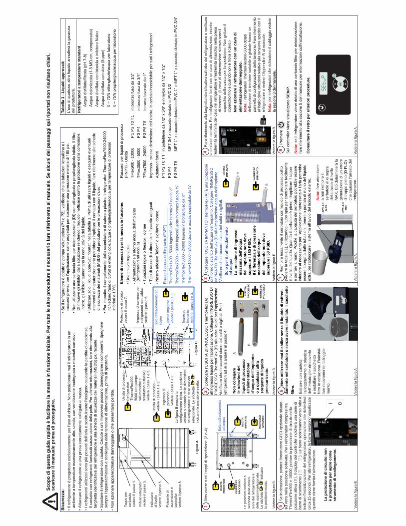
3 C
olle
gare
l'U
SC
ITA
IMP
IAN
TO T
herm
oFle
x (A
) a u
na tu
bazi
one
di ri
torn
o o
scar
ico
dell'a
cqua
del
l'impi
anto
. Col
lega
re l'
ING
RE
SS
O
IMP
IAN
TO T
herm
oFle
x (B
) all'a
limen
tazi
one
acqu
a de
ll'im
pian
to.
Verificare che i raccordi siano bel saldi e sigillati.
Elem
enti
nece
ssar
i per
la m
essa
in fu
nzio
ne:
Una
chi
ave
rego
labi
leA
limen
tazi
one
e rit
orno
acq
ua d
ell'im
pian
to
(r
efrig
erat
ori a
d ac
qua)
Tubazioni rigide o flessibili idonee
Tipo
di r
acco
rdi o
dim
ensi
oni f
asce
tte a
degu
ati
Nastro adesivo Teflon
® o
sig
illan
te id
oneo
Sicu
rezz
a:•
Il re
frige
rato
re è
pro
getta
to e
sclu
siva
men
te p
er l'
uso
al c
hius
o. N
on p
osiz
iona
re m
ai il
refri
gera
tore
in u
n
ambi
ente
a te
mpe
ratu
re e
cces
siva
men
te a
lte, u
mid
o, c
on v
entil
azio
ne in
adeg
uata
o m
ater
iali
corr
osiv
i.•
Atta
ccar
e il
refri
gera
tore
a u
na p
resa
cor
retta
men
te c
olle
gata
a m
assa
. •
I ref
riger
anti
utili
zzat
i son
o pi
ù pe
sant
i del
l'aria
e s
ostit
uira
nno
l'oss
igen
o ca
usan
do la
per
dita
di c
osci
enza
. Il
cont
atto
con
refri
gera
nti f
uoriu
sciti
cau
sa u
stio
ni d
ella
pel
le. P
er u
lterio
ri in
form
azio
ni, f
are
rifer
imen
to a
lla
targhetta identificativa del refrigeratore e alla scheda di sicurezza dei materiali (MSDS) più recente.
• S
post
are
il re
frige
rato
re c
on c
aute
la. C
adut
e o
urti
impr
ovvi
si p
osso
no d
anne
ggia
rne
i com
pone
nti.
Spe
gner
e
sem
pre
l'app
arec
chia
tura
e s
colle
garla
dal
la te
nsio
ne d
i alim
enta
zion
e, p
rima
di s
post
arla
.•
Non
azi
onar
e ap
pare
cchi
atur
e da
nneg
giat
e o
che
pres
enta
no p
erdi
te.
Solo
per
il ra
ffred
dam
ento
ad
acq
ua.
Vedere la figura B.
Vedere la figura B.
Vedere la figura A.
Vedere la figura A.
B
A
2 C
olle
gare
l'USCITA DI PROCESSO
The
rmoF
lex
(A)
all'in
gres
so li
quid
i per
l'ap
plic
azio
ne. C
olle
gare
l'INGRESSO DI
PR
OC
ES
SO
The
rmoF
lex
(B) a
ll'usc
ita li
quid
i per
l'ap
plic
azio
ne.
Verificare che i raccordi siano bel saldi e sigillati. Per i
refri
gera
tori
ad a
ria a
ndar
e al
pas
so 4
.
B
A
ING
RES
SOPR
OC
ESSO
USC
ITA
PRO
CES
SO
ING
RES
SOIM
PIA
NTO
USC
ITA
IMPI
AN
TO
Vedere la figura B.
5 S
e in
dot
azio
ne, p
orta
re l'i
nter
rutto
re G
FCI o
pzio
nale
situ
ato
sul r
etro
nel
la p
osiz
ione
sol
leva
ta. P
er i
refri
gera
tori
com
pres
i tra
Th
erm
oFle
x900
e 1
0000
, por
tare
la p
rote
zion
e di
circ
uito
nel
la
posi
zion
e at
tiva
( I ).
Il d
ispl
ay d
el c
ontro
ller i
ndic
herà
una
ser
ie d
i ba
rre d
i sco
rrim
ento
( ).
Le
barre
sco
rrera
nno
vers
o l'a
lto a
in
dica
re l'i
nizi
aliz
zazi
one
del r
efrig
erat
ore;
ope
razi
one
che
richi
eder
à ci
rca
15 s
econ
di. P
er a
ltri r
efrig
erat
ori,
le b
arre
ven
gono
vis
ualiz
zate
qu
ando
vie
ne fo
rnita
l'alim
enta
zion
e.
4 Fare riferimento alla targhetta identificativa sul retro del refrigeratore e verificare
la te
nsio
ne c
orre
tta. P
er i
refri
gera
tori
forn
iti co
n un
cav
o di
alim
enta
zion
e, in
serir
e l'e
stre
mità
fem
min
a de
l cav
o ne
l ref
riger
ator
e e
l'est
rem
ità m
asch
io n
ella
pre
sa
di c
orre
nte.
(Il c
avo
di a
limen
tazi
one
si tr
ova
sotto
il
cope
rchi
o de
lla c
assa
per
la s
pedi
zion
e. N
on g
etta
re il
coperchio fino a quando non si trova il cavo.)
Non
azi
onar
e il
refr
iger
ator
e co
n un
cav
o di
al
imen
tazi
one
dann
eggi
ato.
Not
a: i r
efrig
erat
ori T
herm
oFle
x900
-500
0 do
tati
dell'o
pzio
ne d
i ten
sion
e va
riabi
le o
glo
bale
han
no u
n pannello di configurazione della tensione. Fare riferimento
al fo
glio
del
le is
truzi
oni r
elat
ive
alla
tens
ione
spe
dito
con
il
refri
gera
tore
o v
eder
e l'A
ppen
dice
B a
l man
uale
.N
ota:
per
i re
frige
rato
ri ch
e ric
hied
ono
il cab
lagg
io v
eder
e la
sez
ione
3 d
el m
anua
le.
+ -
ente
r
mode
Tabe
lla 1
- Li
quid
i app
rova
ti:
L'us
o di
qua
lsia
si a
ltro
liqui
do a
nnul
lerà
la g
aran
zia
de
l pro
dutto
re.
Ref
riger
ator
i a te
mpe
ratu
re s
tand
ard
Acqua distillata/filtrata (pH 7-8)
Acqua deionizzata (1-3 MΩ-cm, compensata)
A
cqua
dis
tilla
ta c
on b
ioci
da o
inib
itore
Nal
co
A
cqua
dis
tilla
ta c
on c
loro
(5 p
pm)
0 – 75% etilenglicole/acqua per laboratorio
0 – 75% propilenglicole/acqua per laboratorio
Rac
cord
i acq
ua d
ell'im
pian
to (F
NPT
)Th
erm
oFle
x140
0 - 5
000
Ingr
essi/
uscit
e in
bro
nzo
fuso
da
½"
ThermoFlex7500 - 10000 Ingressi/uscite in bronzo fuso da ¾"
ThermoFlex15000 - 24000 Ingressi in bronzo fuso da ¾"
ThermoFlex15000 - 24000 Uscite in acciaio inossidabile da ¾"
Pul
sant
e di
ac
cens
ione
e
cont
rolle
rvedere il passo 8.
Imbu
to in
tegr
ato
vede
re il
pas
so 5
.
Indi
cato
re
di li
vello
ve
dere
il p
asso
5.
Figu
ra A
Tapp
o pe
r se
rbat
oio
vede
re il
pas
so 4
.
Usc
ita d
i pro
cess
o -
vede
re i
pass
i 1 e
2.
Usc
ita d
i pro
cess
o -
(ref
riger
ator
i Th
erm
oFle
x900
- 50
00 c
on p
ompe
vo
lum
etric
he e
trasduttori di flusso)
vede
re i
pass
i 1 e
2.
Pro
tezi
one
di c
ircui
to
vedere il passo 7.
Ingr
esso
di c
orre
nte
per
refri
gera
tori
non
cabl
ati
vede
re il
pas
so 6
.
Ingr
esso
di
proc
esso
- ve
dere
i pa
ssi 1
e 2
.
Ingr
esso
im
pian
tove
dere
i pa
ssi 1
e 3
.
Usc
ita im
pian
to
vede
re i
pass
i 1 e
3.
Sol
o ra
ffred
dam
ento
ad
acqu
a
Figu
ra B
La figura B mostra la
configurazione tipica. Le posizioni
varia
no a
sec
onda
del
le d
imen
sion
i de
l ref
riger
ator
e e
delle
opz
ioni
se
lezi
onat
e. L
e et
iche
tte
indi
cano
la p
osiz
ione
esa
tta.
1 R
imuo
vere
tutti
i ta
ppi d
i spe
dizi
one
(2 o
4).
Vedere la figura B.
Sol
o ra
ffred
dam
ento
ad
acq
ua
ING
RES
SOIM
PIA
NTO
USC
ITA
IMPI
AN
TO
ING
RES
SOPR
OC
ESSO
USC
ITA
PRO
CES
SO
Le p
osiz
ioni
var
iano
a
seco
nda
delle
dim
en-
sion
i del
refri
gera
tore
e
delle
opz
ioni
sel
ezio
nate
. Le
etic
hette
indi
cano
la
pos
izio
ne e
satta
.
Rac
cord
i per
liqu
idi d
i pro
cess
o
(FN
PT)
- U
scita
TF
lex9
00 -
1000
0
P 1
P 2
T0 T
1
in b
ronz
o fu
so d
a 1/
2"TF
lex3
500
- 500
0
P 3
P 4
in
bro
nzo
fuso
da
3/4"
TFlex7500 - 24000 P 3 P 5 T 5
in rame lavorato da 1"
Ingr
esso
- st
essa
dim
ensi
one
dell'u
scita
, in
acci
aio
inos
sida
bile
per
tutti
i re
frige
rato
riA
datta
tori
forn
itiP 1 P 2 T 0 T 1 in polietilene da 1/2" x 3/8'' e in nylon da 1/2" x 1/2"
P 3
P 4
M
PT
3/4
x ra
ccor
do d
enta
to in
PV
C 1
/2P
3 P
5 T
5 M
PT
1" x
racc
ordo
den
tato
in P
VC
1" e
MP
T 1"
x ra
ccor
do d
enta
to in
PV
C 3
/4"
8 P
rem
ere
.
Sul
con
trolle
r vie
ne v
isua
lizza
to S
EtuP
.
Not
a: se il refrigeratore viene dotato di una cartuccia filtro per deionizzazione
fare
rife
rimen
to a
lla s
ezio
ne 5
del
man
uale
per
info
rmaz
ioni
sul
l'inst
alla
zion
e.
Con
sulta
re il
retr
o pe
r ulte
riori
proc
edur
e.
Scop
o di
que
sta
guid
a ra
pida
è fa
cilit
are
la m
essa
in fu
nzio
ne in
izia
le. P
er tu
tte le
altr
e pr
oced
ure
è ne
cess
ario
fare
rife
rimen
to a
l man
uale
. Se
alcu
ni d
ei p
assa
ggi q
ui ri
port
ati n
on ri
sulta
no c
hiar
i, sc
aric
are
il m
anua
le p
rima
di p
rose
guire
.
La p
ress
ione
di i
ngre
sso
mas
sim
a de
ll'ac
qua
dell'
impi
anto
non
dev
e su
pera
re i
150
PSIG
. Il
diffe
renz
iale
di p
ress
ione
m
assi
mo
dell'
acqu
a de
ll'im
pian
to n
on d
eve
supe
rare
i 50
PSI
D.
LIVE
LLO
MIN
LIVE
LLO
MA
X
Vedere la figura A.
Not
a: fa
re a
ttenz
ione
a
non
riem
pire
il
serb
atoi
o al
di s
opra
de
lla ta
cca
di li
vello
M
AX. C
iò d
eter
min
erà
la
gene
razi
one
di u
n er
rore
di
trop
po p
ieno
(O F
LO)
che
caus
erà
l'arre
sto
del
refri
gera
tore
.
7 R
iem
pire
lent
amen
te il
ser
bato
io c
on li
quid
o di
pro
cess
o pu
lito
(ved
ere
la ta
bella
1),
utili
zzan
do il
tubo
spi
a pe
r con
trolla
re fa
cilm
ente
il
livel
lo d
el li
quid
o. Q
uand
o il
serb
atoi
o è
pien
o, ri
appl
icar
e il
tapp
o e
serr
are
a m
ano.
Poi
ché
la c
apac
ità d
el s
erba
toio
pot
rebb
e es
sere
in
ferio
re a
l nec
essa
rio p
er l'
appl
icaz
ione
inte
ress
ata
e l'a
ria p
otre
bbe
esse
re s
purg
ata
dalle
tuba
zion
i, te
nere
a p
orta
ta d
i man
o de
l liq
uido
ex
tra p
er ra
bboc
care
il s
iste
ma
all'a
vvio
del
rici
rcol
o es
tern
o.
Vedere la figura B.
La p
rote
zion
e di
circ
uito
non
è
prog
etta
ta p
er a
gire
com
e st
rum
ento
di s
colle
gam
ento
.
• Se il refrigeratore è dotato di pompa volumetrica (P1 o P2), verificare che le tubazioni idrauliche e i
raccordi previsti per l'applicazione siano progettati per sostenere una pressione minima di 185 psi.
• Non utilizzare una cartuccia filtro per deionizzazione (DI) con etilenglicole o propilenglicole inibito. Il filtro
DI rimuove gli inibitori dalla soluzione rendendo il liquido inefficace contro la protezione dalla corrosione.
In
oltre
, gli
inib
itori
aum
enta
no la
con
dutti
vità
del
liqu
ido.
• U
tiliz
zare
sol
o i l
iqui
di a
ppro
vati
ripor
tati
nella
tabe
lla 1
. Prim
a di
util
izza
re li
quid
i o e
segu
ire e
vent
uali
inte
rven
ti di
man
uten
zion
e ch
e po
trebb
ero
impl
icar
e il
cont
atto
con
il li
quid
o, fa
re ri
ferim
ento
alle
sch
ede
di sicurezza dei materiali (MSDS) del produttore per le precauzioni d'uso.
• Per impedire il congelamento dello scambiatore di calore a piastre, i refrigeratori ThermoFlex7500-24000
richi
edon
o l'u
so d
i 50/
50 d
i etil
engl
icol
e/ac
qua
o pr
opile
nglic
ole/
acqu
a pe
r tem
pera
ture
di p
roce
sso
infe
riori
a 10
°C.
Non
col
lega
re
le tu
bazi
oni d
ei
liqui
di d
i pro
cess
o al
l'alim
enta
zion
e d'
acqu
a de
ll'im
pian
to
o a
qual
sias
i altr
a so
rgen
te d
i liq
uido
pr
essu
rizza
to.
6 N
on u
tiliz
zare
mai
il c
hille
r sen
za il
liqu
ido
di ra
ffred
-da
men
to n
el s
erba
toio
o s
enza
ave
re in
stal
lato
il s
acch
etto
Est
rarr
e co
n ca
utel
a l’a
llogg
iam
ento
in p
last
ica
dell’
imbu
to p
er ri
muo
verlo
e
inst
alla
re il
sac
chet
to
filtro in dotazione. Reinstal-
lare
nuo
vam
ente
l’al
logg
ia-
men
to.
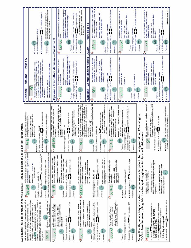
Pre
mer
e Il
disp
lay
lam
pegg
erà
tra H
i t e
42
Se
desi
dera
to, u
tiliz
zare
per
rego
lare
il v
alor
e
Pre
mer
e p
er p
assa
re a
l dis
play
suc
cess
ivo
Pre
mer
e eIl
disp
lay
lam
pegg
erà
tra L
o t e
3
Se
desi
dera
to, u
tiliz
zare
per
rego
lare
il v
alor
e
Pre
mer
e
Lo t
impo
sta
il lim
ite d
i alla
rme
ba
ssa
tem
pera
tura
del
liqu
ido.
Inte
rval
lo: D
a +3
°C a
+42
°C
fabb
rica:
3°C
Pre
mer
e Il
disp
lay
lam
pegg
erà
tra H
i P1
Se
desi
dera
to, u
tiliz
zare
per
rego
lare
il v
alor
e
Pre
mer
e
Hi P
1 im
post
a il
limite
di a
llarm
e sc
aric
o al
ta p
ress
ione
del
la p
ompa
.
Inte
rval
lo: v
aria
bile
a s
econ
da d
ella
po
mpa
varia
bile
a s
econ
da d
ella
pom
paIl
disp
lay
lam
pegg
erà
tra d
ELAY
e 0
Se
desi
dera
to, u
tiliz
zare
per
rego
lare
il v
alor
e
Pre
mer
e
dELA
Y è
il te
mpo
am
mes
so o
ltre
il lim
ite
di a
llarm
e H
i P1
prim
a ch
e la
pom
pa
veng
a sp
enta
.
Inte
rval
lo: v
aria
bile
a s
econ
da d
ella
pom
pa
0 se
cond
i
Pre
mer
e eIl
disp
lay
lam
pegg
erà
tra L
o P1
Se
desi
dera
to, u
tiliz
zare
p
er re
gola
re il
val
ore
Pre
mer
e .Lo
P1
impo
sta
il lim
ite d
i alla
rme
scar
ico
bass
a pr
essi
one
della
pom
pa.
Inte
rval
lo: v
aria
bile
a s
econ
da d
ella
po
mpa
fabb
rica:
var
iabi
le a
sec
onda
del
la
pom
pa
dELA
Y è
il te
mpo
am
mes
so o
ltre
il lim
ite d
i alla
rme
Lo P
1 pr
ima
che
la
pom
pa v
enga
spe
nta.
Inte
rval
lo: d
a 0
a 30
sec
ondi
fabb
rica:
10
seco
ndi
Il di
spla
y la
mpe
gger
à tra
dEL
AY e
10
Se
desi
dera
to, u
tiliz
zare
p
er re
gola
re il
val
ore
Pre
mer
e .
Pre
mer
e Il
disp
lay
lam
pegg
erà
tra A
Lr e
fLt
Se
desi
dera
to, p
rem
ere
per
vis
ualiz
zare
indC
Pre
mer
e .
Atti
va o
dis
attiv
a l'a
llarm
e ac
ustic
o de
l ref
riger
ator
e.
Inte
rval
lo: o
n o
OFF
Impo
staz
ione
Pre
mer
e Il
disp
lay
lam
pegg
erà
tra S
ound
e o
n
Se
desi
dera
to, p
rem
ere
per
vis
ualiz
zare
OFF
Pre
mer
e .
Pre
mer
e Il
disp
lay
lam
pegg
erà
tra S
tArt
e O
FF
Se
desi
dera
to, p
rem
ere
per
vis
ualiz
zare
ON
Pre
mer
e .
StA
rt a
ttiva
/dis
attiv
a il
riavv
io
auto
mat
ico.
Inte
rval
lo: o
n o
OFF
fabb
rica:
OFF
Pre
mer
e Il
disp
lay
lam
pegg
erà
tra C
ArE
e L
1
Se
desi
dera
to, u
tiliz
zare
per
cam
biar
e la
mod
alità
del
Pre
mer
e .C
ArE
vie
ne u
tiliz
zato
per
impo
star
e il
prom
emor
ia d
i fre
quen
za m
anut
enzi
one
liqui
do d
el re
frig
erat
ore.
Inte
rval
lo: o
ff, L
1 - 1
000
hour
s, L
2 - 2
000
hour
s,
L3 -3
000
hour
s
Pre
mer
e p
er s
alva
re tu
tte
Pre
mer
e tu
tte
Se d
esid
erat
o, p
rem
ere
A qu
esto
pun
to la
pro
cedu
ra d
i
All'
avvi
o de
l ref
riger
ator
e, s
ul c
ontr
olle
r vi
ene
visu
aliz
zata
la te
mpe
ratu
ra d
el li
quid
o di
pro
cess
o.
refr
iger
ator
e pr
emen
do
SP v
iene
util
izza
to p
er re
gola
re il
val
ore
di
impo
staz
ione
.In
terv
allo
: da
+5°C
a +
40°C
Il di
spla
y la
mpe
gger
à tra
SP
e 20
Se
desi
dera
to, u
tiliz
zare
Pre
mer
e .
Se a
pplic
abile
, ved
ere
i riq
uadr
i a d
estr
a pe
r im
post
are
le o
pzio
ni. P
er i
refr
iger
ator
i con
I/O
ana
logi
co
(AC
OM
), fa
re ri
ferim
ento
alla
gui
da d
i avv
io ra
pido
agg
iunt
iva
forn
ita c
on il
refr
iger
ator
e.
Avvi
o ra
pido
- so
lo p
er la
mes
sa in
ser
vizi
o in
izia
le —
ese
guire
dal
pas
so 9
al 2
0 pe
r tut
ti i r
efrig
erat
ori.
** fL
t = g
uast
o (s
pegn
imen
to)
** in
dC =
seg
nala
zion
e (fu
nzio
nam
ento
no
rmal
e)
Hi t
impo
sta
il lim
ite d
ell'a
llarm
e al
ta te
mpe
ratu
ra d
el li
quid
o.
Inte
rval
lo: D
a +3
°C a
+42
°C
fabb
rica:
+42
°C P
rem
ere
Ildi
spla
y la
mpe
ggia
tra
Uni
tS e
°C
Se d
esid
erat
o, u
tiliz
zare
Pre
mer
e p
er p
assa
re a
l dis
play
suc
cess
ivo
Pre
mer
e Il
disp
lay
lam
pegg
erà
tra u
id e
1Se
des
ider
ato,
utili
zzar
e
Pre
mer
e .
HiF
LO im
post
a il
limite
di a
llarm
e
Inte
rval
lo: v
aria
bile
a s
econ
da d
ella
po
mpa
varia
bile
a s
econ
da d
ella
pom
pa P
rem
ere
Il di
spla
y la
mpe
gger
à tra
HiF
LOS
e de
side
rato
, util
izza
re
per
rego
lare
il v
alor
e
Pre
mer
e .
LoFL
O
bass
o.
Inte
rval
lo: v
aria
bile
a s
econ
da d
ella
pom
pa
varia
bile
a s
econ
da d
ella
pom
pa
Pre
mer
e Il
disp
lay
lam
pegg
erà
tra S
toP
e 1
Se d
esid
erat
o, u
tilizz
are
Pre
mer
e .
StoP
vie
ne u
tiliz
zato
per
indi
care
il
num
ero
di b
it di
arr
esto
.
Inte
rval
lo: 2
o 1
fa
bbric
a: 1
u id
(ID
uni
tà) v
iene
util
izza
to s
olo
in
RS4
85. I
ndic
a i d
ispo
sitiv
i col
lega
ti
alla
por
ta R
S485
.
Inte
rval
lo: d
a 1
a 99
fabb
rica:
1
Pre
mer
e Il
disp
lay
lam
pegg
erà
tra S
Er e
OFF
Se
desi
dera
to, u
tiliz
zare
Pre
mer
e .
SEr v
iene
util
izza
to p
er a
ttiva
re/
mod
alità
di c
omun
icaz
ione
ser
iale
.
Inte
rval
lo: o
ff, rS
232,
rS48
5
fabb
rica:
off
Pre
mer
e Il
disp
lay
lam
pegg
erà
tra B
Aud
e 9
600
Se
desi
dera
to, u
tiliz
zare
Pre
mer
e .
BA
ud v
iene
util
izza
to p
er s
elez
iona
re la
ve
loci
tà d
i tra
smis
sion
e in
bau
d pe
r le
com
unic
azio
ni s
eria
li.
Inte
rval
lo: 9
600,
480
0, 2
400,
120
0,
600
o 30
0 bi
t al s
econ
do.
Pre
mer
e Il
disp
lay
lam
pegg
erà
tra d
AtA
e 8
Pre
mer
e
pg .
dAtA
vie
ne u
tiliz
zato
per
vis
ualiz
zare
il
num
ero
di b
it.
Dis
play
: 8
Pre
mer
e Il
disp
lay
lam
pegg
erà
tra P
Ar e
non
eSe
des
ider
ato,
utili
zzar
e
Pre
mer
e .
PAr v
iene
util
izza
to c
ome
stru
men
to
di c
ontr
ollo
per
gli
erro
ri di
co
mun
icaz
ione
.
Inte
rval
lo: e
ven,
odd
o n
one
fabb
rica:
non
e
Se il
refr
iger
ator
e no
n di
spon
e di
com
unic
azio
ni s
eria
li, v
eder
e il
pass
o 20
.
Vede
re il
pas
so 2
0
Opz
ione
- C
omun
icaz
ioni
ser
iali
(DC
OM
) — P
assi
da
D a
I
Uni
tS s
ono
le s
cale
del
la te
mpe
ratu
ra,
e d
ella
pr
essi
one.
Scal
e: °C
/°F
G
PM/L
PM
PSI/B
ar/K
PAS
Pre
mer
e
Il di
spla
y la
mpe
gger
à tra
HZ
e 60
Pre
mer
e .
Se il
refri
gera
tore
non
dis
pone
di u
n
seria
li, v
eder
e il
pass
o 20
.
Opz
ione
- Te
nsio
ne —
Pas
so A
in e
ntra
ta p
er i
refr
iger
ator
i con
pom
pe P
3 - P
5 e
la c
apac
ità d
i fun
zion
amen
to a
50
Hz
o 60
Hz.
La
freq
uenz
a se
lezi
onat
a re
gola
aut
omat
icam
ente
Inte
rval
lo: 5
0 H
z o
60 H
z
I
Pre
mer
e
NOTA
:
poss
ibile
NO
TA Q
uest
a fu
nzio
ne è
atti
va s
olo
se il
vede
re il
pas
so 1
6.
NO
TA Q
uest
a fu
nzio
ne è
atti
va s
olo
se il
vede
re il
pas
so 1
6.
ai li
miti
di a
llarm
e te
mpe
ratu
ra, p
ress
ione
che
funz
iona
men
to n
orm
ale
(indC
). Pe
r ul
terio
ri in
form
azio
ni, v
eder
e la
sez
ione
4
nel m
anua
le.
Inte
rval
lo: f
Lt* o
indC
**
Il re
frig
erat
ore
vien
e av
viat
o
auto
mat
icam
ente
.
Il di
spla
y si
spe
gner
à.
Pre
mer
e Il
disp
lay
lam
pegg
erà
tra L
oFLO
Se
desi
dera
to, u
tiliz
zare
p
er re
gola
re il
val
ore
Pre
mer
e .
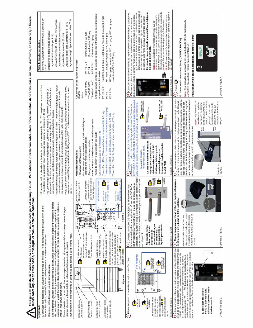
3 C
onec
te la
SA
LID
A D
E L
A IN
STA
LAC
IÓN
de
Ther
moF
lex
(A) a
un
des
agüe
o c
ondu
cto
de re
torn
o de
agu
a a
la in
stal
ació
n. C
onec
te la
E
NTR
AD
A A
LA IN
STA
LAC
IÓN
de
Ther
moF
lex
(B) a
un
sum
inis
tro d
e ag
ua.
Asegúrese de que las conexiones se han cerrado y fijado correctamente.
Mat
eria
les
nece
sario
s:Una llave inglesa ajustable
Inst
alac
ione
s pa
ra e
l sum
inis
tro y
el r
etor
no d
el a
gua
(enf
riado
res
refri
gera
dos
por a
gua)
Manguera o tuberías apropiadas
Abrazaderas o conexiones con el tamaño adecuado
Cinta de Teflon®
o u
n se
llado
r ade
cuad
o
Segu
ridad
:•
El e
nfria
dor e
stá
dest
inad
o ex
clus
ivam
ente
par
a us
o en
inte
riore
s. N
o lo
col
oque
nun
ca e
n lu
gare
s co
n ca
lor o
hu
med
ad e
xces
ivos
, ven
tilac
ión
inad
ecua
da o
pre
senc
ia d
e m
ater
iale
s co
rros
ivos
.•
Con
ecte
el e
nfria
dor a
una
tom
a de
tier
ra a
decu
ada.
• Los refrigerantes utilizados son más pesados que el aire, por lo que sustituirán al oxígeno y provocarán la pérdida
del c
onoc
imie
nto.
En
caso
de
que
entre
en
cont
acto
con
el r
efrig
eran
te p
roce
dent
e de
fuga
s, s
e pr
oduc
irán
quemaduras en la piel. Consulte la placa identificativa del enfriador y la hoja de datos de seguridad de materiales
(MSDS) más actual del fabricante.
• Mueva el enfriador con cuidado. Los saltos repentinos o las caídas pueden dañar sus componentes. Apague
siempre el equipo y desconéctelo de la tensión eléctrica antes de moverlo.
• Nunca ponga en funcionamiento un equipo que esté dañado o que presente fugas.
Solo
par
a eq
uipo
s re
frig
erad
os p
or a
gua.
Con
sulte
la F
igur
a B
.C
onsu
lte la
Fig
ura
B.
Con
sulte
la F
igur
a A
.C
onsu
lte la
Fig
ura
A.
B
A
2 C
onec
te la
SA
LID
A D
E P
RO
CE
SO
de
Ther
moF
lex
(A) a
la entrada de líquidos de su aplicación. Conecte la E
NTR
AD
A D
E P
RO
CE
SO
de ThermoFlex (B) a la salida de líquidos de su
aplic
ació
n. Asegúrese de que las conexiones se han cerrado y fijado
corr
ecta
men
te. P
ara
los
enfri
ador
es re
frige
rado
s po
r aire
, con
tinúe
co
n el
pas
o 4.
B
A
ENTR
AD
A D
EPR
OC
ESO
SALI
DA
DE
PRO
CES
O
ENTR
AD
A A
LAIN
STA
LAC
IÓN
SALI
DA
DE
LAIN
STA
LAC
IÓN
Con
sulte
la F
igur
a B
.
5 S
i se
sum
inis
tra, c
oloq
ue e
n po
sici
ón v
ertic
al e
l dis
yunt
or G
FCI q
ue
se ubica en la parte posterior. Para los enfriadores ThermoFlex900 hasta
10.000, coloque el protector del circuito en la posición de encendido
( I ). En la pantalla del controlador aparecerá una serie de barras
de desplazamiento (
). Las barras se desplazarán hacia
arriba, indicando que el enfriador se está inicializando. Este proceso
dura 15 segundos aproximadamente. En otros enfriadores, las barras
aparecen cuando el enfriador recibe alimentación eléctrica.
4 Consulte la placa identificativa de la parte posterior del enfriador y compruebe
la tensión apropiada. Para los enfriadores que se suministran con un cable de
alimentación, inserte el extremo hembra del cable de alimentación en el enfriador
y, a continuación, inserte el extremo macho del cable de
alimentación en la toma eléctrica (el cable de alimentación
se ubica debajo de la tapa de la caja de transporte. No
deseche la tapa hasta que haya encontrado el cable).
En c
aso
de q
ue e
l cab
le d
e al
imen
taci
ón e
sté
daña
do,
no u
tilic
e el
enf
riado
r .
Not
a: Los enfriadores ThermoFlex900-5000 que se
suministran con la opción de tensión variable o de tensión
global disponen de un panel de configuración de la tensión.
Consulte la hoja de instrucciones sobre tensión suministrada
con el enfriador o consulte el apéndice B del manual.
Not
a: Para obtener información sobre los enfriadores que
requieren conectarse mediante cables, consulte la sección 3
del m
anua
l.
+ -
ente
r
mode
Tabl
a 1:
líqu
idos
apr
obad
os
El uso de cualquier otro líquido anula la garantía del
clie
nte.
En
fria
dore
s de
tem
pera
tura
est
ánda
r Agua filtrada/destilada (pH 7 - 8)
Agua desionizada (1 - 3 MΩ-cm, compensada)
Agua destilada con inhibidor y biocida Nalco
A
gua
dest
ilada
con
clo
ro (5
ppm
) Agua/etilenglicol para laboratorio al 0 - 75 %
Agua/propilenglicol para laboratorio al 0 - 75 %
Con
exio
nes
para
agu
a de
la in
stal
ació
n (F
NP
T)ThermoFlex1400 - 5000 entrada/salida, bronce fundido, 0,5 pulg
ThermoFlex7500 - 10.000 entrada/salida, bronce fundido, 0,75 pulg
ThermoFlex15000 - 24.000 entrada, bronce fundido, 0,75 pulg
ThermoFlex15000 - 24.000 salida, acero inoxidable, 0,75 pulg
Controlador y botón
de e
ncen
dido
Consulte el paso 8.
Embudo integrado
Con
sulte
el p
aso
5.
Indi
cado
r de
nive
l C
onsu
lte e
l pas
o 5.
Figu
ra A
Tapó
n de
l dep
ósito
C
onsu
lte e
l pas
o 4.
Sal
ida
del p
roce
so:
Consulte los pasos 1 y 2.
Sal
ida
del p
roce
so:
(enf
riado
res
ThermoFlex900-5000 con
bombas PD y transductores
de flujo)
Consulte los pasos 1 y 2.
Pro
tect
or d
el c
ircui
to
Consulte el paso 7.
Ent
rada
de
alim
enta-
ción
par
a en
friad
ores
que no incluyen cables
Con
sulte
el p
aso
6.
Ent
rada
del
pro
ceso
:Consulte los pasos 1 y 2.
Ent
rada
a la
in
stal
ació
nConsulte los pasos 1 y 3.
Sal
ida
de la
in
stal
ació
n
Consulte los pasos 1 y 3.
Sol
o re
frige
rado
por
agu
a
Figu
ra B
En la figura B se muestra un equipo
normal. Las ubicaciones varían en
función del tamaño del enfriador
y de
las
opci
ones
sel
ecci
onad
as.
Las
etiq
ueta
s identifican la
ubicación exacta.
1 Retire los plásticos de embalaje de los enchufes (2 o 4).
Con
sulte
la F
igur
a B
.
Sol
o re
frige
rado
po
r agu
a
ENTR
AD
A A
LAIN
STA
LAC
IÓN
SALI
DA
DE
LAIN
STA
LAC
IÓN
ENTR
AD
A D
EPR
OC
ESO
SALI
DA
DE
PRO
CES
O
Las ubicaciones varían
en función del tamaño
del e
nfria
dor y
de
las
opci
ones
sel
ecci
onad
as.
Las
etiq
ueta
s
identifican la ubicación
exac
ta.
Conexiones de los líquidos de proceso
(FN
PT)
Sal
ida
TFlex900: 10.000
P 1 P 2 T0 T 1 Bronce fundido, 0,5 pulg
TFlex3500: 5000
P 3 P 4
Bronce fundido, 0,75 pulg
TFlex7500: 24.000
P 3 P 5 T 5
Cobre forjado, 1 pulg
Entrada: tamaño idéntico al de la salida de todos los enfriadores de acero inoxidable
Ada
ptad
ores
sum
inis
trado
sP 1 P 2 T0 T 1 Polietileno de 0,5 pulg x 0,375 pulg y nailon de 0,5 pulg x 0,5 pulg
P 3 P 4
MPT de 0,75 pulg x conector de PVC de 0,5 pulg
P 3 P 5 T 5
MPT de 1 pulg x conector de PVC de 1 pulg y MPT de 1 pulg x
conector de PVC de 0,75 pulg
8 P
ulse
.
En
el c
ontro
lado
r se
mos
trará
Set
up (C
ON
FIG
UR
AC
IÓN
).
Not
a: Si el enfriador se suministra con un cartucho de filtro de desionización,
cons
ulte
la s
ecci
ón 5
del
man
ual p
ara
su in
stal
ació
n.
Para
con
ocer
los
paso
s ad
icio
nale
s, c
onsu
lte e
l dor
so.
Esta
guí
a de
pue
sta
en m
arch
a rá
pida
se
ha e
labo
rado
úni
cam
ente
par
a el
arr
anqu
e in
icia
l. Pa
ra o
bten
er in
form
ació
n so
bre
otro
s pr
oced
imie
ntos
, deb
e co
nsul
tar e
l man
ual.
Asi
mis
mo,
en
caso
de
que
tuvi
era
duda
s so
bre
algu
no d
e es
tos
paso
s, d
esca
rgue
el m
anua
l ant
es d
e co
ntin
uar.
La p
resi
ón m
áxim
a de
ent
rada
de
l agu
a en
la in
stal
ació
n no
de
be e
xced
er lo
s 15
0 PS
IG.
El d
ifere
ncia
l de
la p
resi
ón
máx
ima
del a
gua
en la
in
stal
ació
n no
deb
e ex
cede
r lo
s 50
PSI
D.
NIV
ELM
ÍN.
NIV
ELM
ÁX.
Con
sulte
la
Figu
ra A
.
Not
a: T
enga
cui
dado
de
no re
llena
r el d
epós
ito
por encima de la línea
de NIVEL MÁXIMO de
llena
do. D
e lo
con
trario
, ge
nera
rá u
n er
ror d
e desbordamiento en la
unid
ad (O
FLO
) que
ha
rá q
ue e
l enf
riado
r se
apag
ue.
7 L
enta
men
te rellene el depósito con líquido de proceso limpio (consulte
la tabla 1). Utilice el tubo de control de nivel para controlar con facilidad el
nivel de líquido. Cuando el depósito esté lleno, vuelva a colocar el tapón del
depósito y apriételo a mano. Y
a qu
e la
cap
acid
ad d
el d
epós
ito p
uede
ser
pequeña para la aplicación de que se trate y posiblemente deba purgar el
aire de los tubos, tenga a mano líquido extra para mantener el sistema lleno
al m
áxim
o cu
ando
se
inic
ie la
circ
ulac
ión
exte
rna.
Con
sulte
la F
igur
a B
.
El p
rote
ctor
del
circ
uito
no
se
ha d
iseñ
ado
para
ut
iliza
rse
com
o un
med
io
de d
esco
nexi
ón.
• Si la unidad está provista de una bomba de desplazamiento positivo (P1 o P2), asegúrese de que los tubos
y conectores de su aplicación tienen capacidad para soportar un mínimo de 185 psi.
• No utilice ningún cartucho de filtro de desionización (DI) con EG inhibido o PG inhibido. Los filtros de DI
eliminarán los inhibidores de la solución, lo que provocará que el líquido no ofrezca protección frente a la
corrosión. Asimismo, los inhibidores incrementarán la conductividad de los líquidos.
• Utilice únicamente los líquidos aprobados que se muestran en la Tabla 1. Antes de utilizar líquidos o realizar
tare
as d
e m
ante
nim
ient
o en
las
que
pued
a en
trar e
n co
ntac
to c
on e
llos,
con
sulte
las
prec
auci
ones
de
manipulación en las hojas de datos de seguridad de materiales (MSDS) del fabricante.
• Para evitar que el intercambiador de placas se congele o acristale, los enfriadores ThermoFlex7500-24000
requieren el uso de EG/agua de 50/50 o de PG/agua de 50/50 por debajo de una temperatura de proceso
de 10 °C.
No
cone
cte
nunc
a tu
bos
con
líqui
do
de p
roce
so a
l su
min
istr
o de
agu
a de
l cen
tro
ni a
ni
ngun
a fu
ente
de
líqui
do p
resu
rizad
o.
6 N
unca
pon
ga e
n m
arch
a el
chi
ller s
in lí
quid
o re
frig
eran
te
Tire
con
cui
dado
la c
arca
sa d
e plástico del embudo para quitarla
e instalar la bolsa de filtro sumi-
nist
rada
. Rei
nsta
lar d
e nu
evo
la
carc
asa.
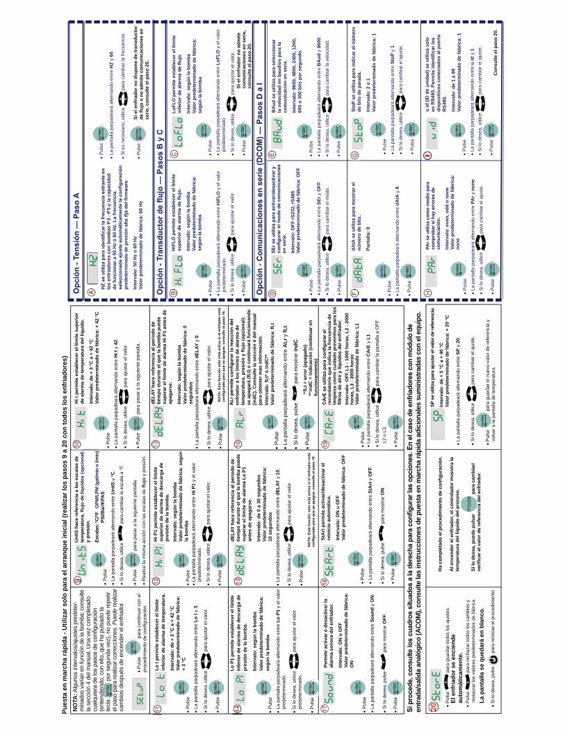
Pul
se
.La
pan
talla
par
pade
ará
alte
rnan
do e
ntre
Hi t
y 4
2.
Si l
o de
sea,
util
ice
par
a aj
usta
r el v
alor
.
Pul
se
par
a pa
sar a
la s
igui
ente
pan
talla
.
Pul
se
.La
pan
talla
par
pade
ará
alte
rnan
do e
ntre
Lo
t y 3
.
Si l
o de
sea,
util
ice
par
a aj
usta
r el v
alor
.
Pul
se
.
Lo t
perm
ite e
stab
lece
r el l
ímite
in
ferio
r de
alar
ma
de te
mpe
ratu
ra.
Inte
rval
o: d
e +
3 °C
a +
42
°CVa
lor p
rede
term
inad
o de
fábr
ica:
+
3 °C
Pul
se
.La
pan
talla
par
pade
ará
alte
rnan
do e
ntre
Hi P
1 y
el v
alor
pred
eter
min
ado.
Si l
o de
sea,
util
ice
par
a aj
usta
r el v
alor
.
Pul
se
.
Hi P
1 pe
rmite
est
able
cer e
l lím
ite
supe
rior d
e al
arm
a de
des
carg
a de
pr
esió
n de
la b
omba
.In
terv
alo:
seg
ún la
bom
baVa
lor p
rede
term
inad
o de
fábr
ica:
seg
ún
la b
omba
La p
anta
lla p
arpa
dear
á al
tern
ando
ent
re d
ELAY
y 0
.
Si l
o de
sea,
util
ice
par
a aj
usta
r el v
alor
.
Pul
se
.
dELA
Y ha
ce re
fere
ncia
al p
erio
do d
e tie
mpo
dur
ante
el q
ue la
bom
ba p
uede
su
pera
r el l
ímite
de
alar
ma
Hi P
1 an
tes
de
apag
arse
.
Inte
rval
o: s
egún
la b
omba
Valo
r pre
dete
rmin
ado
de fá
bric
a: 0
se
gund
os
Pul
se
.La
pan
talla
par
pade
ará
alte
rnan
do e
ntre
Lo
P1 y
el v
alor
p
rede
term
inad
o.
Si l
o de
sea,
util
ice
par
a aj
usta
r el v
alor
p
rede
term
inad
o.
Pul
se
.
Lo P
1 pe
rmite
est
able
cer e
l lím
ite
infe
rior d
e al
arm
a de
des
carg
a de
pr
esió
n de
la b
omba
.
Inte
rval
o: s
egún
la b
omba
Va
lor p
rede
term
inad
o de
fábr
ica:
se
gún
la b
omba
dELA
Y ha
ce re
fere
ncia
al p
erio
do d
e tie
mpo
dur
ante
el q
ue la
bom
ba p
uede
su
pera
r el l
ímite
de
alar
ma
Lo P
1
ante
s de
apa
gars
e.
Inte
rval
o: d
e 0
a 30
seg
undo
sVa
lor p
rede
term
inad
o de
fábr
ica:
10
seg
undo
sLa
pan
talla
par
pade
ará
alte
rnan
do e
ntre
dEL
AY y
10.
Si l
o de
sea,
util
ice
par
a aj
usta
r el v
alor
.
Pul
se
.
Pul
se
.La
pan
talla
par
pade
ará
alte
rnan
do e
ntre
ALr
y fL
t.
Si l
o de
sea,
pul
se
par
a m
ostra
r ind
C.
Pul
se
.
Perm
ite a
ctiv
ar o
des
activ
ar la
al
arm
a so
nora
del
enf
riado
r.
Inte
rval
o: O
N u
OFF
Valo
r pre
dete
rmin
ado
de fá
bric
a:
ON
Pul
se
.La
pan
talla
par
pade
ará
alte
rnan
do e
ntre
Sou
nd y
ON
.
Si l
o de
sea,
pul
se
par
a m
ostra
r OFF
.
Pul
se
.
Pul
se
.La
pan
talla
par
pade
ará
alte
rnan
do e
ntre
StA
rt y
OFF
.
Si l
o de
sea,
pul
se
par
a m
ostra
r ON
.
Pul
se
.
StA
rt p
erm
ite a
ctiv
ar/d
esac
tivar
el
rein
icio
aut
omát
ico.
Inte
rval
o: O
N u
OFF
Valo
r pre
dete
rmin
ado
de fá
bric
a: O
FF
Pul
se
.La
pan
talla
par
pade
ará
alte
rnan
do e
ntre
CA
rE y
L1.
Si l
o de
sea,
util
ice
par
a ca
mbi
ar la
pan
talla
a O
FF
L2
o L
3.
Pul
se
.
reco
rdat
orio
que
indi
ca la
frec
uenc
ia d
e lim
piez
a co
mo
cuid
ado
prev
entiv
o pa
ra lo
s
Inte
rval
o: O
FF L
1 - 1
000
hora
s, L
2 - 2
000
hora
s, L
3 - 3
000
hora
sVa
lor p
rede
term
inad
o de
fábr
ica:
L1
Pul
se
par
a gu
arda
r tod
os lo
s aj
uste
s.
Pul
se
par
a re
chaz
ar to
dos
los
cam
bios
y
rest
aura
r los
val
ores
pre
dete
rmin
ados
de
fábr
ica.
Si lo
des
ea, p
ulse
p
ara
rein
icia
r el p
roce
dim
ient
o.
Al e
ncen
der e
l enf
riado
r, el
con
trol
ador
mue
stra
la
tem
pera
tura
del
líqu
ido
del p
roce
so.
Si lo
des
ea, p
uede
pul
sar
par
a ca
mbi
ar/
SP s
e ut
iliza
par
a aj
usta
r el v
alor
de
refe
renc
ia.
Inte
rval
o: d
e +
5 °C
a +
40
°C
Valo
r pre
dete
rmin
ado
de fá
bric
a: +
20
°C
La p
anta
lla p
arpa
dear
á al
tern
ando
ent
re S
P y
20.
Si l
o de
sea,
util
ice
par
a ca
mbi
ar e
l aju
ste.
Pul
se
par
a gu
arda
r el n
uevo
val
or d
e re
fere
ncia
y
vol
ver a
la p
anta
lla d
e te
mpe
ratu
ra.
entra
da/s
alid
a an
alóg
ico
(ACO
M),
cons
ulte
las
inst
rucc
ione
s de
pue
sta
en m
arch
a rá
pida
adi
cion
ales
sum
inis
trada
s co
n el
equ
ipo.
Pues
ta e
n m
arch
a rá
pida
- U
tiliz
ar s
olo
para
el a
rran
que
inic
ial (
real
izar
los
paso
s 9
a 20
con
todo
s lo
s en
fria
dore
s)
** fL
t = e
rror
(apa
gado
)**
indC
= in
dica
ción
(con
tinua
r en
func
iona
mie
nto)
Hi t
per
mite
est
able
cer e
l lím
ite s
uper
ior
de a
larm
a de
tem
pera
tura
del
líqu
ido.
Inte
rval
o: d
e +
3 °C
a +
42
°CVa
lor p
rede
term
inad
o de
fábr
ica:
+ 4
2 °C
Pul
se
.La
pan
talla
par
pade
ará
alte
rnan
do e
ntre
Uni
tS y
°C.
Si l
o de
sea,
util
ice
par
a ca
mbi
ar la
esc
ala
a °F
.
Pul
se
par
a pa
sar a
la s
igui
ente
pan
talla
.
Rea
lice
la m
ism
a ac
ción
con
las
esca
las
de
y p
resi
ón.
Pul
se
.La
pan
talla
par
pade
ará
alte
rnan
do e
ntre
u id
y 1
.S
i lo
dese
a, u
tilic
e p
ara
cam
biar
el a
just
e.
Pul
se
.
HiF
LO p
erm
ite e
stab
lece
r el l
ímite
Inte
rval
o: s
egún
la b
omba
Valo
r pre
dete
rmin
ado
de fá
bric
a:
segú
n la
bom
ba
Pul
se
.La
pan
talla
par
pade
ará
alte
rnan
do e
ntre
HiF
LO y
el v
alor
pred
eter
min
ado.
Si l
o de
sea,
util
ice
par
a aj
usta
r el v
alor
.
Pul
se
.
LoFL
O p
erm
ite e
stab
lece
r el l
ímite
Inte
rval
o: s
egún
la b
omba
Valo
r pre
dete
rmin
ado
de fá
bric
a:
segú
n la
bom
ba
Pul
se
.La
pan
talla
par
pade
ará
alte
rnan
do e
ntre
Sto
P y
1.S
i lo
dese
a, u
tilic
e p
ara
cam
biar
el a
just
e.
Pul
se
.
StoP
se
utili
za p
ara
indi
car e
l núm
ero
de b
its d
e pa
rada
.
Inte
rval
o: 2
o 1
Va
lor p
rede
term
inad
o de
fábr
ica:
1
u id
(ID
de
unid
ad) s
e ut
iliza
sol
o
disp
ositi
vos
cone
ctad
os a
l pue
rto
RS4
85.
Inte
rval
o: d
e 1
a 99
Va
lor p
rede
term
inad
o de
fábr
ica:
1
Pul
se
.La
pan
talla
par
pade
ará
alte
rnan
do e
ntre
SEr
y O
FF.
Si l
o de
sea,
util
ice
par
a ca
mbi
ar e
l mod
o.
Pul
se
.
en s
erie
.
Inte
rval
o: O
FF rS
232,
rS48
5 Va
lor p
rede
term
inad
o de
fábr
ica:
OFF
Pul
se
.La
pan
talla
par
pade
ará
alte
rnan
do e
ntre
BA
ud y
960
0.S
i lo
dese
a, u
tilic
e p
ara
cam
biar
la v
eloc
idad
.
Pul
se
.
BA
ud s
e ut
iliza
par
a se
lecc
iona
r la
vel
ocid
ad e
n ba
udio
s pa
ra la
co
mun
icac
ión
en s
erie
.
Inte
rval
o: 9
600,
480
0, 2
400,
120
0,
600
o 30
0 bi
ts p
or s
egun
do.
Pul
se
.La
pan
talla
par
pade
ará
alte
rnan
do e
ntre
dA
tA y
8.
Pul
se.
dAtA
se
utili
za p
ara
mos
trar
el
núm
ero
de b
its.
Pant
alla
: 8
Pul
se
.La
pan
talla
par
pade
ará
alte
rnan
do e
ntre
PA
r y n
one.
Si l
o de
sea,
util
ice
par
a ca
mbi
ar e
l aju
ste.
Pul
se
.
PAr s
e ut
iliza
com
o m
edio
par
a
com
unic
ació
n.
Inte
rval
o: e
ven,
odd
o n
one
Valo
r pre
dete
rmin
ado
de fá
bric
a:
none
Si e
l enf
riado
r no
adm
ite
com
unic
acio
nes
en s
erie
, co
nsul
te e
l pas
o 20
.
Con
sulte
el p
aso
20.
Uni
tS h
ace
refe
renc
ia a
las
esca
las
de
tem
pera
tura
,
Esca
las:
°C/°F
G
PM/L
PM (g
al/m
in o
l/m
in)
PS
I/Bar
/KPA
S P
ulse
.
La p
anta
lla p
arpa
dear
á al
tern
ando
ent
re H
Z y
60.
Si e
s ne
cesa
rio, u
tilic
e p
ara
cam
biar
la fr
ecue
ncia
.
Pul
se
.Si
el e
nfria
dor n
o di
spon
e de
tran
sduc
tor
serie
, con
sulte
el p
aso
20.
los
enfr
iado
res
con
bom
bas
P 3
- P 5
y la
cap
acid
ad
de fu
ncio
nar a
50
Hz
o 60
Hz.
La
frec
uenc
ia
pred
eter
min
ada
de p
resi
ón a
lta
Inte
rval
o: 5
0 H
z o
60 H
zVa
lor p
rede
term
inad
o de
fábr
ica:
60
Hz
I
Pul
se
par
a co
ntin
uar c
on e
l
NO
TA: A
lgun
os in
terv
alos
/aju
stes
pre
dete
r-m
inad
os v
aría
n en
func
ión
de la
bom
ba; c
onsu
lte
la s
ecci
ón 4
del
man
ual.
Una
vez
com
plet
ado
(ent
endi
endo
, con
ello
, que
ha
puls
ado
la
tecl
a
por
seg
unda
vez
), no
pue
de re
petir
el
pas
o pa
ra re
aliza
r cor
recc
ione
s. P
uede
real
izar
cam
bios
des
pués
de
ence
nder
el e
nfria
dor.
NO
TA: E
sta
func
ión
solo
est
á ac
tiva
si e
l enf
riado
r est
á
NO
TA: E
sta
func
ión
solo
est
á ac
tiva
si e
l enf
riado
r est
á
enfr
iado
r a lo
s lím
ites
de a
larm
a de
se a
paga
rá (f
Lt) o
con
tinua
rá fu
ncio
nand
o (in
dC).
Con
sulte
la s
ecci
ón 4
del
man
ual
para
obt
ener
más
info
rmac
ión.
Inte
rval
o: fL
t* o
indC
**Va
lor p
rede
term
inad
o de
fábr
ica:
fLt
El e
nfria
dor s
e en
cien
de
auto
mát
icam
ente
.
La p
anta
lla s
e qu
edar
á en
bla
nco.
Pul
se
.La
pan
talla
par
pade
ará
alte
rnan
do e
ntre
LoF
LO y
el v
alor
pred
eter
min
ado.
Si l
o de
sea,
util
ice
par
a aj
usta
r el v
alor
.
Pul
se
.
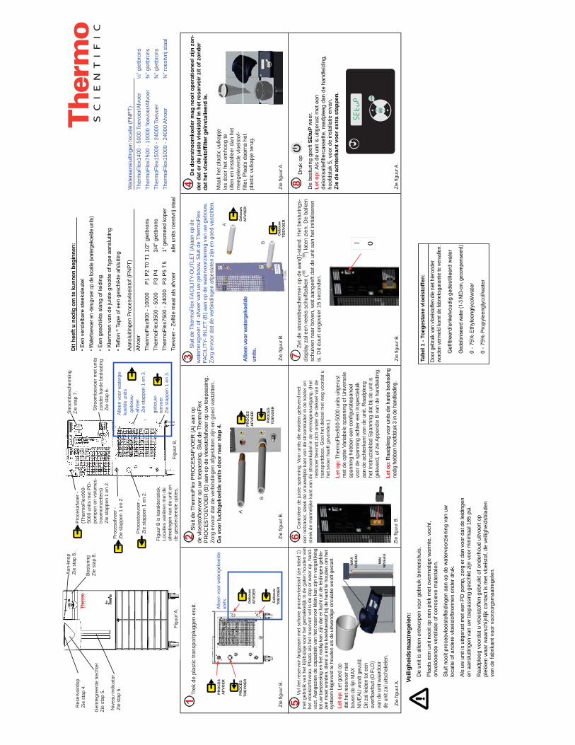
MIN
NIV
EAU
MA
XN
IVEA
U
Vul
het
rese
rvoi
r lan
gzaa
m m
et s
chon
e pr
oces
vloe
isto
f (zi
e ta
bel 1
) m
et g
ebru
ik v
an h
et k
ijkbu
isje
voo
r het
gem
akke
lijk
in d
e ga
ten
houd
en v
an
het v
loei
stof
nive
au. P
laat
s al
s he
t res
ervo
ir vo
l is
de d
op e
r wee
r op,
han
d-va
st. A
ange
zien
de
capa
cite
it va
n he
t res
ervo
ir kl
ein
kan
zijn
in v
erge
lijki
ng
tot u
w to
epas
sing
en
het n
odig
kan
zijn
dat
er l
ucht
uit
de le
idin
gen
gebl
a-ze
n m
oet w
orde
n, d
ient
u e
xtra
koe
lvlo
eist
of b
ij de
han
d te
hou
den
om h
et
syst
eem
bijg
evul
d te
hou
den
als
de u
itwen
dige
circ
ulat
ie w
ordt
ges
tart.
Dru
k op
.
De
best
urin
g ge
eft S
EtuP
wee
r. Le
t op:
Als
de
unit
is u
itger
ust m
et e
en
deïonisatiefiltercassette, raadpleeg dan de handleiding,
hoof
dstu
k 5,
voo
r de
inst
alla
tie e
rvan
.Zi
e de
ach
terk
ant v
oor e
xtra
sta
ppen
.
Trek
de
plas
tic tr
ansp
ortp
lugg
en e
ruit.
Pro
cesa
fvoe
r -
Zie
stap
pen
1 en
2.
Pro
cesa
fvoe
r -
(The
rmoF
lex9
00-
5000
uni
ts m
et P
D-
pom
pen
en v
olum
es-
troom
omze
tters
) Zi
e st
appe
n 1
en 2
.
Stro
ombe
sche
rmin
g Zi
e st
ap 7
.
Stro
omto
evoe
r met
uni
ts
zond
er h
arde
bed
radi
ngZi
e st
ap 6
.
Pro
cest
oevo
er -
Zie
stap
pen
1 en
2.
Figu
ur B
is k
arak
teris
tiek.
Lo
catie
s va
riëre
n m
et d
e af
met
inge
n va
n de
uni
t en
de g
esel
ecte
erde
opt
ies.
De
door
stro
omko
eler
mag
noo
it op
erat
ione
el z
ijn z
on-
der d
at e
r de
juis
te v
loei
stof
in h
et re
serv
oir z
it of
zon
der
Con
trole
er d
e ju
iste
spa
nnin
g. V
oor u
nits
die
wor
den
gele
verd
met
ee
n ne
tsno
er, s
teek
de
vrou
wel
ijke
kant
van
de
stro
omka
bel i
n de
koe
ler e
n st
eek
de m
anne
lijke
kan
t van
de
stro
omka
bel i
n de
ver
mog
ensu
itgan
g. (H
et
nets
noer
bev
indt
zic
h on
der d
e de
ksel
van
de
trans
portd
oos.
Goo
i het
dek
sel n
iet w
eg v
oord
at u
he
t sno
er h
eeft
gevo
nden
.)
Slu
it de
The
rmoF
lex
FAC
ILIT
Y-O
UTL
ET
(A)a
an o
p de
w
ater
teru
gvoe
r of -
afvo
er v
an u
w g
ebou
w. S
luit
de T
herm
oFle
x FA
CIL
ITY-
INLE
T (B
) aan
op
de w
ater
voor
zien
ing
van
uw g
ebou
w.
Zorg
erv
oor d
at d
e ve
rbin
ding
en a
fges
lote
n zi
jn e
n go
ed v
astz
itten
.
gebo
uw-
toev
oer
Zie
stap
pen
1 en
3.
gebo
uw-
afvo
er
Zie
stap
pen
1 en
3.
Alle
en v
oor w
ater
ge-
koel
de u
nits
Dit
heef
t u n
odig
om
te k
unne
n be
ginn
en:
• Een verstelbare steeksleutel
• Watertoevoer en -terugvoer op de locatie (watergekoelde units)
• Een geschikte slang of leiding
• Klemmen van de juiste grootte of type aansluiting
• Teflon ®
Tap
e of
een
ges
chik
te a
fslu
iting
Alle
en v
oor w
ater
geko
elde
un
its
Veili
ghei
dsm
aatr
egel
en:
De
unit
is a
lleen
ont
wor
pen
voor
geb
ruik
bin
nens
huis
.
Pla
ats
een
unit
nooi
t op
een
plek
met
ove
rmat
ige
war
mte
, voc
ht,
onvo
ldoe
nde
vent
ilatie
of c
orro
siev
e m
ater
iale
n.
Sluit nooit procesvloeistofleidingen aan op de watervoorziening van uw
loca
tie o
f and
ere
vloe
isto
fbro
nnen
ond
er d
ruk.
Als
uw u
nit i
s ui
tger
ust m
et e
en P
D p
omp,
zor
g er
dan
voo
r dat
de
leid
inge
n en
aan
slui
tinge
n va
n uw
toep
assi
ng g
esch
ikt z
ijn v
oor m
inim
aal 1
85 p
si.
Raa
dple
eg v
oord
at u
vlo
eist
offe
n ge
brui
kt o
f ond
erho
ud u
itvoe
rt op
pl
ekke
n w
aar w
aars
chijn
lijk
cont
act i
s m
et v
loei
stof
, de
veili
ghei
dsbl
aden
va
n de
fabr
ikan
t voo
r voo
rzor
gsm
aatre
gele
n.
Figu
ur B
.
Alle
en v
oor w
ater
geko
elde
un
its.
Zie figuur A.
Zie figuur B.
Zie figuur B.
Zie figuur B.
Zie figuur B.
Zie figuur B.
Zie figuur A.
Zie figuur A.
Slu
it de
The
rmoF
lex
PR
OC
ES
AFV
OE
R (A
) aan
op
de v
loei
stof
toev
oer o
p uw
toep
assi
ng. S
luit
de T
herm
oFle
x P
RO
CE
STO
EV
OE
R (B
) aan
op
de v
loei
stof
afvo
er o
p uw
toep
assi
ng.
Zorg
erv
oor d
at d
e ve
rbin
ding
en a
fges
lote
n zi
jn e
n go
ed v
astz
itten
. G
a vo
or lu
chtg
ekoe
lde
units
doo
r naa
r sta
p 4.
Zet
de
stro
ombe
sche
rmer
op
de a
an(I)
-sta
nd. H
et b
estu
rings
-di
spla
y za
l een
reek
s sc
huifb
alke
n (
) lat
en z
ien.
De
balk
en
schu
iven
naa
r bov
en, w
at a
ange
eft d
at d
e un
it aa
n he
t ini
tialis
eren
is
. Dit
duur
t ong
evee
r 15
seco
nden
.
B
A
B
A
Bes
turin
g Zi
e st
ap 8
.
Aan
-kno
pZi
e st
ap 8
.
Geï
nteg
reer
de tr
echt
erZi
e st
ap 5
.
Niv
eau-
indi
cato
rZi
e st
ap 5
.
Figu
ur A
.
Res
ervo
irdop
Zie
stap
4.
PRO
CES
TOEV
OER
PRO
CES
AFV
OER
Geb
ouw
TOEV
OER
Geb
ouw
AFV
OER
Geb
ouw
TOEV
OER
Geb
ouw
AFV
OER
PRO
CES
TOEV
OER
PRO
CES
AFV
OER
Let o
p: L
et g
oed
op
dat h
et re
serv
oir n
iet
bove
n de
lijn
MAX
N
IVEA
U w
ordt
gev
uld.
D
it za
l leid
en to
t een
overflowfout (O FLO)
van
de u
nit w
aard
oor
de u
nit z
al u
itsch
akel
en.
Aan
slui
tinge
n P
roce
svlo
eist
of (F
NP
T)A
fvoe
r Th
erm
oFle
x900
- 10
000
P1
P2
T0 T
1 1/
2” g
ietb
rons
Ther
moF
lex3
500
- 500
0 P
3 P
4 3/
4” g
ietb
rons
Ther
moF
lex7
500
- 240
00
P3
P5
T 5
1” g
esm
eed
kope
rTo
evoe
r - Z
elfd
e m
aat a
ls a
fvoe
r al
le u
nits
roes
tvrij
sta
al
Wateraansluitingen locatie (FNPT)
Ther
moF
lex1
400
- 500
0 To
evoe
r/Afv
oer
½” g
ietb
rons
Th
erm
oFle
x750
0 - 1
0000
Toe
voer
/Afv
oer
¾” g
ietb
rons
Ther
moF
lex1
5000
- 24
000
Toev
oer
¾” g
ietb
rons
Ther
moF
lex1
5000
- 24
000
Afv
oer
¾” r
oest
vrij
staa
l
Let o
p: T
herm
oFle
x900
-500
0 un
its u
itger
ust
met
de
optie
Var
iabe
le s
pann
ing
of U
nive
rsel
e spanning hebben een configuratiepaneel
voor
de
span
ning
ach
ter e
en in
spec
tielu
ik
aan
de a
chte
rkan
t van
de
unit.
Raa
dple
eg
het I
nstru
ctie
blad
Spa
nnin
g da
t bij
de u
nit i
s ge
leve
rd, o
f zie
App
endi
x B
van
de h
andl
eidi
ng.
Let o
p: R
aadp
leeg
voo
r uni
ts d
ie h
arde
bed
radi
ng
nodi
g he
bben
hoo
fdst
uk 3
in d
e ha
ndle
idin
g.
Door
geb
ruik
van
vloei
stof
fen
die
niet
hie
rond
er
word
en v
erm
eld
kom
t de
fabr
ieks
gara
ntie
te v
erva
llen.
Gefiltreerd/enkelvoudig gedestilleerd water
Gedeïoniseerd water (1-3 MΩ-cm, gecompenseerd)
0
- 75%
Eth
ylee
ngly
col/w
ater
0
- 75%
Pro
pyle
engl
ycol
/wat
er
Tabe
l 1 -
Toeg
esta
ne v
loei
stof
fen:
+ -
ente
r
mode
Maa
k he
t pla
stic
vul
kapj
e lo
s do
or h
et o
mho
og te
til
len
en in
stal
leer
dan
het
m
eege
leve
rde
vloe
isto
f-filter. Plaats daarna het
plas
tic v
ulka
pje
teru
g.
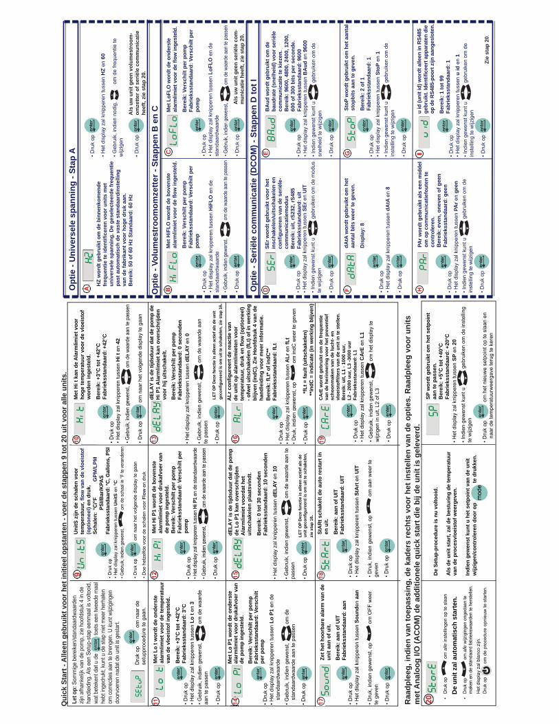
• Dru
k op
• H
et d
ispl
ay z
al k
nipp
eren
tuss
en H
i t e
n 42
• Geb
ruik,
indi
en g
ewen
st,
om
de
waa
rde
aan
te p
asse
n
• Dru
k op
g om
naa
r het
vol
gend
e di
spla
y te
gaa
n
• Dru
k op
• H
et d
ispl
ay z
al k
nipp
eren
tuss
en L
o t e
n 3
• Geb
ruik
, ind
ien
gew
enst
, o
m d
e w
aard
e aa
n te
pas
sen
• Dru
k op
Met
Lo
t wor
dt d
e on
ders
te
alar
mlim
iet v
oor d
e te
mpe
ratu
ur
van
de v
loei
stof
inge
stel
d.
Ber
eik:
+3°
C to
t +42
°CFa
brie
ksst
anda
ard:
3°C
• Dru
k op
• H
et d
isplay
zal k
nippe
ren
tuss
en H
i P1
en d
e sta
ndaa
rdwa
arde
• Geb
ruik,
indie
n ge
wens
t, o
m d
e wa
arde
aan
te p
asse
n
• Dru
k op
g
Met
Hi P
1 w
ordt
de
bove
nste
al
arm
limie
t voo
r dru
kafv
oer v
an
de p
omp
inge
stel
d.B
erei
k: V
ersc
hilt
per p
omp
Fabr
ieks
stan
daar
d: V
ersc
hilt
per
pom
p• H
et d
ispl
ay z
al k
nipp
eren
tuss
en d
ELAY
en
0
• Geb
ruik
, ind
ien
gew
enst
, o
m d
e w
aard
e aa
n te
pas
sen
• Dru
k op
dELA
Y is
de
tijds
duur
dat
de
pom
p de
H
i P1
Ala
rmlim
iet k
an o
vers
chrij
den
voor
hij
uits
chak
elt.
Ber
eik:
Ver
schi
lt pe
r pom
pFa
brie
ksst
anda
ard:
0 s
econ
den
• Dru
k op
• H
et d
ispl
ay z
al k
nipp
eren
tuss
en L
o P1
en
de
stan
daar
dwaa
rde
• Geb
ruik
, ind
ien
gew
enst
, o
m d
e st
anda
ardw
aard
e aa
n te
pas
sen
• Dru
k op
Met
Lo
P1 w
ordt
de
onde
rste
al
arm
limie
t voo
r dru
kafv
oer v
an
de p
omp
inge
stel
d.B
erei
k: V
ersc
hilt
per p
omp
Fabr
ieks
stan
daar
d: V
ersc
hilt
per p
omp
dELA
Y is
de
tijds
duur
dat
de
pom
p de
Lo
P1 k
an o
vers
chrij
den
Ala
rmlim
iet v
oord
at h
et
uits
chak
elen
pla
atsv
indt
.
Ber
eik:
0 to
t 30
seco
nden
Fabr
ieks
stan
daar
d: 1
0 se
cond
en
• Het
dis
play
zal
kni
pper
en tu
ssen
dEL
AY e
n 10
• Geb
ruik
, ind
ien
gew
enst
, o
m d
e w
aard
e aa
n te
pa
ssen
• Dru
k op
• Dru
k op
• H
et d
ispl
ay z
al k
nipp
eren
tuss
en A
Lr e
n fL
t• D
ruk,
indi
en g
ewen
st, o
p o
m in
dC w
eer t
e ge
ven
• Dru
k op
g
Zet h
et h
oorb
are
alar
m v
an d
e un
it aa
n of
uit.
Ber
eik:
aan
of U
ITFa
brie
ksst
anda
ard:
aan
• Dru
k op
• H
et d
ispl
ay z
al k
nipp
eren
tuss
en S
ound
en a
an
• Dru
k, in
dien
gew
enst
, op
om
OFF
wee
r te
gev
en
• Dru
k op
• Dru
k op
• H
et d
ispl
ay z
al k
nipp
eren
tuss
en S
tArt
en
UIT
• Dru
k, in
dien
gew
enst
, op
om
aan
wee
r te
geve
n
• Dru
k op
StA
Rt s
chak
elt d
e au
to re
star
t in
en u
it.
Ber
eik:
aan
of U
ITFa
brie
ksst
anda
ard:
UIT
• Dru
k op
• H
et d
ispl
ay z
al k
nipp
eren
tuss
en C
ArE
en
L1• G
ebru
ik, i
ndie
n ge
wen
st,
om
het
dis
play
te
wijz
igen
in u
it, L
2 of
L3
• Dru
k op
CA
rE w
ordt
geb
ruik
t om
de
freq
uent
ie
van
de h
erin
nerin
g vo
or h
et p
reve
ntie
f sc
hoon
mak
en v
an d
e lu
cht-
en
vloe
isto
ffilte
rs v
an d
e un
it in
te s
telle
n.B
erei
k: u
it, L
1 - 1
000
uur,
L2 -
2000
uur
, L3
-300
0 uu
rFa
brie
ksst
anda
ard:
L1
• D
ruk
op
om
alle
inst
ellin
gen
op te
sla
an
D
e un
it za
l aut
omat
isch
sta
rten
.•
Dru
k op
o
m a
lle w
ijzig
inge
n on
geda
an te
m
aken
en
de s
tand
aard
fabr
ieks
waa
rden
te h
erst
elle
n.
Het
dis
play
zal
bla
nco
zijn
.
Dru
k op
o
m d
e pr
oced
ure
opni
euw
te s
tarte
n.
De
Setu
p-pr
oced
ure
is n
u vo
ltooi
d.
Als
de
unit
star
t, za
l de
best
urin
g de
tem
pera
tuur
va
n de
pro
cesv
loei
stof
wee
rgev
en.
Indi
en g
ewen
st k
unt u
het
set
poin
t van
de
unit
wijz
igen
/con
trol
eren
doo
r op
te d
rukk
en.
SP w
ordt
geb
ruik
t om
het
set
poin
t aa
n te
pas
sen.
Ber
eik:
+5°
C to
t +40
°CFa
brie
ksst
anda
ard:
+20
°C• H
et d
ispl
ay z
al k
nipp
eren
tuss
en S
P en
20
• Ind
ien
gew
enst
kun
t u
geb
ruik
en o
m d
e in
stel
ling
te w
ijzig
en
• Dru
k op
o
m h
et n
ieuw
e se
tpoi
nt o
p te
sla
an e
n na
ar d
e te
mpe
ratu
urw
eerg
ave
teru
g te
ker
en
Raa
dple
eg, i
ndie
n va
n to
epas
sing
, de
kade
rs re
chts
voo
r het
inst
elle
n va
n de
opt
ies.
Raa
dple
eg v
oor u
nits
m
et A
nalo
og I/
O (A
CO
M) d
e ad
ditio
nele
qui
ck s
tart
die
bij
de u
nit i
s ge
leve
rd.
Qui
ck S
tart
- A
lleen
geb
ruik
t voo
r het
initi
eel o
psta
rten
- vo
er d
e st
appe
n 9
tot 2
0 ui
t voo
r alle
uni
ts.
** fL
t = fa
ult (
uits
chak
elen
)**
indC
= in
dica
te (i
n w
erki
ng b
lijve
n)
Met
Hi t
kan
de
Ala
rmlim
iet v
oor
hoge
tem
pera
tuur
voo
r de
vloe
isto
f w
orde
n in
gest
eld.
Ber
eik:
+3°
C to
t +42
°CFa
brie
ksst
anda
ard:
+42
°C• D
ruk
op
• Het
dis
play
zal
kni
pper
en tu
ssen
Uni
tS e
n °C
• Geb
ruik,
indi
en g
ewen
st,
om
de
scha
al in
°F te
ver
ande
ren
• Dru
k op
g
om
naa
r het
vol
gend
e di
spla
y te
gaa
n
• Doe
het
zelfd
e vo
or d
e sc
hale
n vo
or F
low
en
druk
• Dru
k op
• H
et d
ispl
ay z
al k
nipp
eren
tuss
en u
id e
n 1
• Ind
ien
gew
enst
kun
t u
geb
ruik
en o
m d
e in
stel
ling
te w
ijzig
en
• Dru
k op
jg
Met
HiF
LO w
ordt
de
bove
nste
al
arm
limie
t voo
r de
flow
inge
stel
d.
Ber
eik:
Ver
schi
lt pe
r pom
pFa
brie
ksst
anda
ard:
Ver
schi
lt pe
r po
mp
• Dru
k op
• H
et d
ispl
ay z
al k
nipp
eren
tuss
en H
iFLO
en
de
stan
daar
dwaa
rde
• Geb
ruik,
indi
en g
ewen
st,
om
de
waar
de a
an te
pas
sen
• Dru
k op
g
• Dru
k op
• H
et d
ispl
ay z
al k
nipp
eren
tuss
en L
oFLO
en
de
stan
daar
dwaa
rde
• Geb
ruik,
indie
n ge
wens
t, o
m d
e wa
arde
aan
te p
asse
n
• Dru
k op
g
Met
LoF
LO w
ordt
de
onde
rste
al
arm
limie
t voo
r de
flow
inge
stel
d.
Ber
eik:
Ver
schi
lt pe
r pom
pFa
brie
ksst
anda
ard:
Ver
schi
lt pe
r po
mp
• Dru
k op
• H
et d
ispl
ay z
al k
nipp
eren
tuss
en S
toP
en 1
• Ind
ien
gew
enst
kun
t u
geb
ruik
en o
m d
e in
stel
ling
te w
ijzig
en
• Dru
k op
jg
StoP
wor
dt g
ebru
ikt o
m h
et a
anta
l st
opbi
ts a
an te
gev
en.
Ber
eik:
2 o
f 1Fa
brie
ksst
anda
ard:
1
u id
(uni
t id)
wor
dt a
lleen
in R
S485
ge
brui
kt. I
dent
ifice
ert a
ppar
aten
die
op
de
RS4
85-p
oort
zijn
aan
gesl
oten
.
Ber
eik:
1 to
t 99
Fabr
ieks
stan
daar
d: 1
• Dru
k op
• H
et d
ispl
ay z
al k
nipp
eren
tuss
en S
Er e
n U
IT• I
ndie
n ge
wen
st k
unt u
g
ebru
iken
om
de
mod
us
te w
ijzig
en
• Dru
k op
SEr w
ordt
geb
ruik
t voo
r het
in
scha
kele
n/ui
tsch
akel
en e
n co
nfigu
rere
n va
n de
ser
iële
-co
mm
unic
atie
mod
usB
erei
k: u
it, rS
232,
rS48
5Fa
brie
ksst
anda
ard:
uit
• Dru
k op
• H
et d
ispl
ay z
al k
nipp
eren
tuss
en B
Aud
en
9600
• Ind
ien
gew
enst
kun
t u
geb
ruik
en o
m d
e sn
elhe
id te
wijz
igen
• Dru
k op
jg
BA
ud w
ordt
geb
ruik
t om
de
baud
rate
(sne
lhei
d) v
oor s
erië
le
com
mun
icat
ie te
kie
zen.
Ber
eik:
960
0, 4
800,
240
0, 1
200,
60
0 of
300
bits
per
sec
onde
.Fa
brie
ksst
anda
ard:
960
0
• Dru
k op
• H
et d
ispl
ay z
al k
nipp
eren
tuss
en d
AtA
en
8
• Dru
k op
y
dAtA
wor
dt g
ebru
ikt o
m h
et
aant
al b
its w
eer t
e ge
ven.
Dis
play
: 8
• Dru
k op
• H
et d
ispl
ay z
al k
nipp
eren
tuss
en P
Ar e
n ge
en• I
ndie
n ge
wen
st k
unt u
g
ebru
iken
om
de
inst
ellin
g te
wijz
igen
• Dru
k op
jg
PAr w
ordt
geb
ruik
t als
een
mid
del
om o
p co
mm
unic
atie
fout
en te
co
ntro
lere
n.B
erei
k: e
ven,
one
ven
of g
een
Fabr
ieks
stan
daar
d: g
een
Opt
ie -
Volu
mes
troo
mom
zette
r - S
tapp
en B
en
C
Als
uw
uni
t gee
n se
riële
com
-m
unic
atie
hee
ft, z
ie s
tap
20.
Zie
stap
20.
Opt
ie -
Serië
le c
omm
unic
atie
(DC
OM
) - S
tapp
en D
tot I
Uni
tS z
ijn d
e sc
hale
n vo
or
tem
pera
tuur
, flow
van
de
vloe
isto
f (o
ptio
neel
) en
druk
.Sc
hale
n: °
C/°F
G
PM/L
PM
PSI/B
ar/K
PAS
Fabr
ieks
stan
daar
d: °C
, Gal
lons
, PSI
• Dru
k op
• Het
dis
play
zal
kni
pper
en tu
ssen
HZ
en 6
0
• Geb
ruik
, ind
ien
nodi
g,
om
de
frequ
entie
te
wijz
igen
• Dru
k op
A
ls u
w u
nit g
een
volu
mes
troo
m-
omze
tter o
f ser
iële
com
mun
icat
ie
heef
t, zi
e st
ap 2
0.
Opt
ie -
Uni
vers
ele
span
ning
- St
ap A
HZ
wor
dt g
ebru
ikt o
m d
e bi
nnen
kom
ende
fr
eque
ntie
te id
entifi
cere
n vo
or u
nits
met
un
iver
sele
spa
nnin
g. D
e ge
sele
ctee
rde
freq
uent
ie
past
aut
omat
isch
de
vast
e st
anda
ardi
nste
lling
va
n de
fabr
ikan
t voo
r hog
e dr
uk a
an.
Ber
eik:
50
of 6
0 H
z St
anda
ard:
60
Hz
I
Dru
k op
o
m n
aar d
e se
tupp
roce
dure
te g
aan.
Let o
p: S
omm
ige
bere
iken/
stan
daar
dwaa
rden
zij
n af
hank
elijk
van
de
pom
p, z
ie h
oofd
stuk
4 in
de
hand
leid
ing.
Als
een
Setu
p-st
ap e
enm
aal is
vol
tooi
d,
wat b
etek
ent d
at u
de
p to
ets
een
twee
de m
aal
hebt
inge
druk
t, ku
nt u
de
stap
nie
t mee
r her
hale
n om
cor
rect
ies
aan
te b
reng
en. U
kun
t wijz
igin
gen
door
voer
en n
adat
de
unit
is ge
star
t.
LET
OP
Dez
e fu
nctie
is a
lleen
act
ief a
ls d
e un
it ge
confi
gure
erd
is o
m u
it te
sch
akel
en, z
ie s
tap
16.
LET
OP
Dez
e fu
nctie
is a
lleen
act
ief a
ls d
e un
it ge
confi
gure
erd
is o
m u
it te
sch
akel
en,
zie
stap
16.
ALr
con
figur
eert
de
reac
tie v
an
de u
nit o
p al
arm
limie
ten
voor
te
mpe
ratu
ur, d
ruk
en fl
ow (o
ptio
neel
) - o
fwel
uits
chak
elen
(fLt
) of i
n w
erki
ng
blijv
en (i
ndC
). Zi
e H
oofd
stuk
4 v
an d
e ha
ndle
idin
g vo
or m
eer i
nfor
mat
ie.
Ber
eik:
fLt*
of i
ndC
**Fa
brie
ksst
anda
ard:
fLt
ThermoFlex i Thermo Scientific
Preface
Compliance Third Party:
CSA Listed - Laboratory equipment-electrical
File # 105974_C_000
CLASS: 8721-05 CAN/CSA-C22.2 No. 61010-1-04
CLASS: 8721-85 ANSI/UL Standard 61010-1
European Union ( EU ) LVD & EMCOur evaluation has demonstrated compliance with EU directives, as indicated by the CE Mark located on the chiller's nameplate and the Declaration of Conformity in the back of this manual.
WEEE This product is required to comply with the European Union’s Waste Electrical & Electronic Equipment (WEEE) Directive 2002/96/EC. It is marked with the following symbol:
Thermo Fisher Scientific has contracted with one or more recycling/disposal companies in each EU Member State, dispose of or recycle this product through them. Further information on Thermo Fisher Scientific’s compliance with these Directives is available at: www.thermoscientific.com/WEEERoHS
After-sale Support Thermo Fisher Scientific is committed to customer service both during and after the sale. If you have questions concerning the chiller operation, or questions concerning spare parts or Service Contracts, call our Sales, Service and Customer Support phone number, see this manual's inside cover for contact information.
When calling, please refer to the labels on the inside cover. These labels list all the necessary information needed to properly identify your chiller.
ii ThermoFlex
Preface
Thermo Scientific
Feedback We appreciate any feedback you can give us on this manual. Please e-mail us at [email protected]. Be sure to include the manual part number and the revision date listed on the front cover.
Warranty Thermo Scientific ThermoFlex chillers have a warranty against defective parts and workmanship for 24 months (excluding MD 1/MD 2 Magnetic Drive and P 1/P 2 Positive Displacement pumps which are warranted for 12 months) from date of shipment. See back page for more details.
Unpacking If the chiller has a line cord it is located under the shipping crate’s lid. Do not discard the lid until the cord is located.
Locate the reservoir fluid filter bag and ensure it installed before the chiller is operated. See Section 3.
Retain all cartons and packing material until the chiller is operated and found to be in good condition. If it shows external or internal damage contact the transportation company and file a damage claim. Under ICC regulations, this is your responsibility.
Out of Box Failure An Out of Box Failure is defined as any product that fails to operate in conformance with sellers published specifications at initial power up. Install the chiller in accordance with manufacturer's recommended operating conditions within 30 days of shipment from the seller.
Any Temperature Control product meeting the definition of an Out of Box Failure must be packed and shipped back in the original packaging to Thermo Fisher Scientific for replacement with a new chiller; seller to pay the cost of shipping. Customer must receive a Return Material Authorization (RMA) from Thermo Fisher prior to shipping.
Thermo Scientific ThermoFlex 1-1
Make sure you read and understand all instructions and safety precautions listed in this manual before installing or operating your chiller. If you have any questions concerning the operation or the information in this manual, please contact us. See inside cover for contact information.
DANGER indicates an imminently hazardous situation which, if not avoided, will result in death or serious injury.
WARNING indicates a potentially hazardous situation which, if not avoided, could result in death or serious injury.
CAUTION indicates a potentially hazardous situation which, if not avoided, may result in minor or moderate injury. It is also be used to alert against unsafe practices.
The lightning flash with arrow symbol, within an equilateral triangle, is intended to alert the user to the presence of non-insulated "dangerous voltage" within the chiller's enclosure. The voltage magnitude is significant enough to constitute a risk of electrical shock.
This label indicates read the manual.
Never place the chiller in a location where excessive heat, moisture, or corrosive materials are present.
The chiller's construction provides protection against the risk of electrical shock by grounding appropriate metal parts. The protection will not function unless the power cord is connected to a properly grounded outlet. It is the user's responsibility to assure a proper ground connection is provided.
Never connect the process fluid inlet or outlet fittings to your building water supply or any water pressure source.
Do not use automotive antifreeze. Commercial antifreeze contains silicates that can damage the pump seals. Use of automotive antifreeze will void the manufacturer’s warranty.
To prevent freezing/glazing of the plate exchanger, ThermoFlex7500 through ThermoFlex24000 chillers require the use of 50/50 EG/water or 50/50 PG/water below 10°C process temperature.
Safety Warnings
Section 1 Safety
DANGER
WARNING
CAUTION
1-2 ThermoFlex
Section 1
Thermo Scientific
Before using any fluid or performing maintenance where contact with the fluid is likely refer to the manufacturer’s MSDS for handling precautions.
When using a process fluid mixture of ethylene glycol and water or propylene glycol and water, check the fluid concentration and pH on a regular basis. Changes in concentration and pH can impact system performance. See Section 3.
Many refrigerants which may be undetectable by human senses are heavier than air and will replace the oxygen in an enclosed area causing loss of consciousness. Contact with leaking refrigerant will cause skin burns. Refer to the chiller's nameplate and the manufacturer's most current MSDS for additional information.
Performance of installation, operation, or maintenance procedures other than those described in this manual may result in a hazardous situation and may void the manufacturer's warranty.
Transport the chiller with care. Sudden jolts or drops can damage its components.
Drain the chiller before it is transported and/or stored in near or below freezing temperatures, see Draining in Section 8. Store the chiller in the temperature range -25°C to 60°C (with packaging), and <80% relative humidity.
For ThermoFlex900-10000 chillers, the circuit protector located on the rear is not intended to act as a disconnecting means.
Observe and never remove warning labels.
Never operate damaged or leaking equipment.
Never operate the chiller without process fluid in the reservoir.
Always turn off the chiller and disconnect the power cord from the power source before performing any service or maintenance procedures, or before moving.
Never operate the chiller with panels removed.
Never operate equipment with damaged power cords.
Refer service and repairs to a qualified technician.
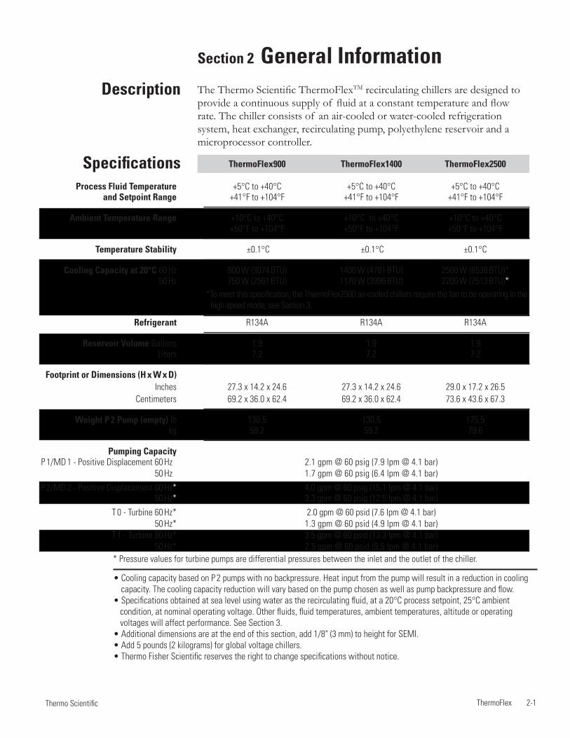
ThermoFlex 2-1 Thermo Scientific
• Cooling capacity based on P 2 pumps with no backpressure. Heat input from the pump will result in a reduction in cooling capacity. The cooling capacity reduction will vary based on the pump chosen as well as pump backpressure and flow.
• Specifications obtained at sea level using water as the recirculating fluid, at a 20°C process setpoint, 25°C ambient condition, at nominal operating voltage. Other fluids, fluid temperatures, ambient temperatures, altitude or operating voltages will affect performance. See Section 3.
• Additional dimensions are at the end of this section, add 1/8" (3 mm) to height for SEMI. • Add 5 pounds (2 kilograms) for global voltage chillers. • Thermo Fisher Scientific reserves the right to change specifications without notice.
Section 2 General InformationThe Thermo Scientific ThermoFlexTM recirculating chillers are designed to provide a continuous supply of fluid at a constant temperature and flow rate. The chiller consists of an air-cooled or water-cooled refrigeration system, heat exchanger, recirculating pump, polyethylene reservoir and a microprocessor controller.
Description
Specifications
* Pressure values for turbine pumps are differential pressures between the inlet and the outlet of the chiller.
ThermoFlex900 ThermoFlex1400 ThermoFlex2500
Process Fluid Temperature +5°C to +40°C +5°C to +40°C +5°C to +40°C and Setpoint Range +41°F to +104°F +41°F to +104°F +41°F to +104°F
Ambient Temperature Range +10°C to +40°C +10°C to +40°C +10°C to +40°C +50°F to +104°F +50°F to +104°F +50°F to +104°F
Temperature Stability ±0.1°C ±0.1°C ±0.1°C
Cooling Capacity at 20°C 60 Hz 900 W (3074 BTU) 1400 W (4781 BTU) 2500 W (8538 BTU)* 50 Hz 750 W (2561 BTU) 1170 W (3996 BTU) 2200 W (7513 BTU)*
Refrigerant R134A R134A R134A
Reservoir Volume Gallons 1.9 1.9 1.9 Liters 7.2 7.2 7.2
Footprint or Dimensions (H x W x D) Inches 27.3 x 14.2 x 24.6 27.3 x 14.2 x 24.6 29.0 x 17.2 x 26.5 Centimeters 69.2 x 36.0 x 62.4 69.2 x 36.0 x 62.4 73.6 x 43.6 x 67.3
Weight P 2 Pump (empty) lb 130.5 130.5 175.5 kg 59.2 59.2 79.6
Pumping Capacity P 1/MD 1 - Positive Displacement 60 Hz* 2.1 gpm @ 60 psig (7.9 lpm @ 4.1 bar) 50 Hz* 1.7 gpm @ 60 psig (6.4 lpm @ 4.1 bar)
P 2/MD 2 - Positive Displacement 60 Hz* 4.0 gpm @ 60 psig (15.1 lpm @ 4.1 bar) 50 Hz* 3.3 gpm @ 60 psig (12.5 lpm @ 4.1 bar)
T 0 - Turbine 60 Hz* 2.0 gpm @ 60 psid (7.6 lpm @ 4.1 bar) 50 Hz* 1.3 gpm @ 60 psid (4.9 lpm @ 4.1 bar) T 1 - Turbine 60 Hz* 3.5 gpm @ 60 psid (13.3 lpm @ 4.1 bar) 50 Hz* 2.5 gpm @ 60 psid (9.5 lpm @ 4.1 bar)
*To meet this specification, the ThermoFlex2500 air-cooled chillers require the fan to be operating in the high-speed mode, see Section 3.
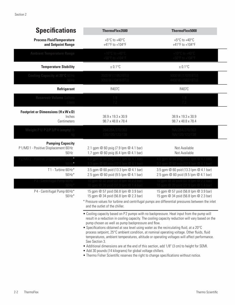
Section 2
2-2 ThermoFlex Thermo Scientific
• Cooling capacity based on P 2 pumps with no backpressure. Heat input from the pump will result in a reduction in cooling capacity. The cooling capacity reduction will vary based on the pump chosen as well as pump backpressure and flow.
• Specifications obtained at sea level using water as the recirculating fluid, at a 20°C process setpoint, 25°C ambient condition, at nominal operating voltage. Other fluids, fluid temperatures, ambient temperatures, altitude or operating voltages will affect performance. See Section 3.
• Additional dimensions are at the end of this section, add 1/8" (3 cm) to height for SEMI. • Add 30 pounds (14 kilograms) for global voltage chillers. • Thermo Fisher Scientific reserves the right to change specifications without notice.
Specifications
* Pressure values for turbine and centrifugal pumps are differential pressures between the inlet and the outlet of the chiller.
ThermoFlex3500 ThermoFlex5000 Process FluidTemperature +5°C to +40°C +5°C to +40°C and Setpoint Range +41°F to +104°F +41°F to +104°F
Ambient Temperature Range +10°C to +40°C +10°C to +40°C +50°F to +104°F +50°F to +104°F
Temperature Stability ± 0.1°C ± 0.1°C
Cooling Capacity at 20°C 60 Hz 3500 W (11953 BTU) 5000 W (17076 BTU) 50 Hz 3050 W (10416 BTU) 4400 W (15027 BTU)
Refrigerant R407C R407C
Reservoir Volume Gallons 1.9 1.9 Liters 7.2 7.2
Footprint or Dimensions (H x W x D) Inches 38.9 x 19.3 x 30.9 38.9 x 19.3 x 30.9 Centimeters 98.7 x 48.8 x 78.4 98.7 x 48.8 x 78.4
Weight P 1/ P 2/P 3/P 4 (empty) lb 264/264/270/303 NA/264/270/303 kg 120/120/123/138 NA/120/123/138
Pumping Capacity P 1/MD 1 - Positive Displacement 60 Hz* 2.1 gpm @ 60 psig (7.9 lpm @ 4.1 bar) Not Available 50 Hz* 1.7 gpm @ 60 psig (6.4 lpm @ 4.1 bar) Not Available
P 2/MD 2 - Positive Displacement 60 Hz* 4.0 gpm @ 60 psig (15.1 lpm @ 4.1 bar) 4.0 gpm @ 60 psig (15.1 lpm @ 4.1 bar) 50 Hz* 3.3 gpm @ 60 psig (12.5 lpm @ 4.1 bar) 3.3 gpm @ 60 psig (12.5 lpm @ 4.1 bar)
T 1 - Turbine 60 Hz* 3.5 gpm @ 60 psid (13.3 lpm @ 4.1 bar) 3.5 gpm @ 60 psid (13.3 lpm @ 4.1 bar) 50 Hz* 2.5 gpm @ 60 psid (9.5 lpm @ 4.1 bar) 2.5 gpm @ 60 psid (9.5 lpm @ 4.1 bar)
P 3 - Centrifugal Pump 60 Hz* 10 gpm @ 32 psid (37.9 lpm @ 2.2 bar) 10 gpm @ 32 psid (37.9 lpm @ 2.2 bar) 50 Hz* 10 gpm @ 20 psid (37.9 lpm @ 1.4 bar) 10 gpm @ 20 psid (37.9 lpm @ 1.4 bar)
P 4 - Centrifugal Pump 60 Hz* 15 gpm @ 57 psid (56.8 lpm @ 3.9 bar) 15 gpm @ 57 psid (56.8 lpm @ 3.9 bar) 50 Hz* 15 gpm @ 34 psid (56.8 lpm @ 2.3 bar) 15 gpm @ 34 psid (56.8 lpm @ 2.3 bar)
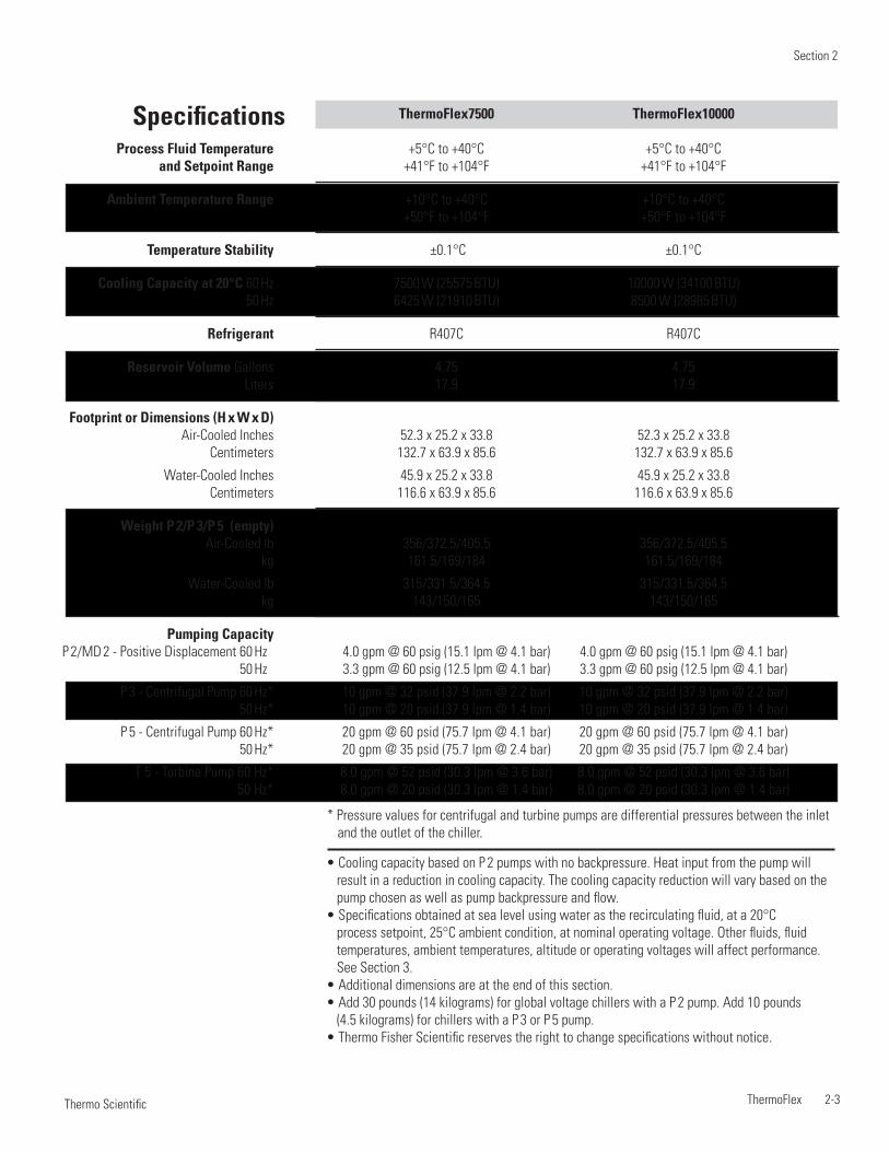
Section 2
ThermoFlex 2-3 Thermo Scientific
• Cooling capacity based on P 2 pumps with no backpressure. Heat input from the pump will result in a reduction in cooling capacity. The cooling capacity reduction will vary based on the pump chosen as well as pump backpressure and flow.
• Specifications obtained at sea level using water as the recirculating fluid, at a 20°C process setpoint, 25°C ambient condition, at nominal operating voltage. Other fluids, fluid temperatures, ambient temperatures, altitude or operating voltages will affect performance. See Section 3.
• Additional dimensions are at the end of this section. • Add 30 pounds (14 kilograms) for global voltage chillers with a P 2 pump. Add 10 pounds
(4.5 kilograms) for chillers with a P 3 or P 5 pump.• Thermo Fisher Scientific reserves the right to change specifications without notice.
Specifications
* Pressure values for centrifugal and turbine pumps are differential pressures between the inlet and the outlet of the chiller.
ThermoFlex7500 ThermoFlex10000 Process Fluid Temperature +5°C to +40°C +5°C to +40°C and Setpoint Range +41°F to +104°F +41°F to +104°F
Ambient Temperature Range +10°C to +40°C +10°C to +40°C +50°F to +104°F +50°F to +104°F
Temperature Stability ±0.1°C ±0.1°C
Cooling Capacity at 20°C 60 Hz 7500 W (25575 BTU) 10000 W (34100 BTU) 50 Hz 6425 W (21910 BTU) 8500 W (28985 BTU)
Refrigerant R407C R407C
Reservoir Volume Gallons 4.75 4.75 Liters 17.9 17.9
Footprint or Dimensions (H x W x D) Air-Cooled Inches 52.3 x 25.2 x 33.8 52.3 x 25.2 x 33.8 Centimeters 132.7 x 63.9 x 85.6 132.7 x 63.9 x 85.6
Water-Cooled Inches 45.9 x 25.2 x 33.8 45.9 x 25.2 x 33.8 Centimeters 116.6 x 63.9 x 85.6 116.6 x 63.9 x 85.6
Weight P 2/P 3/P 5 (empty) Air-Cooled lb 356/372.5/405.5 356/372.5/405.5 kg 161.5/169/184 161.5/169/184
Water-Cooled lb 315/331.5/364.5 315/331.5/364.5 kg 143/150/165 143/150/165
Pumping Capacity P 2/MD 2 - Positive Displacement 60 Hz* 4.0 gpm @ 60 psig (15.1 lpm @ 4.1 bar) 4.0 gpm @ 60 psig (15.1 lpm @ 4.1 bar) 50 Hz* 3.3 gpm @ 60 psig (12.5 lpm @ 4.1 bar) 3.3 gpm @ 60 psig (12.5 lpm @ 4.1 bar)
P 3 - Centrifugal Pump 60 Hz* 10 gpm @ 32 psid (37.9 lpm @ 2.2 bar) 10 gpm @ 32 psid (37.9 lpm @ 2.2 bar) 50 Hz* 10 gpm @ 20 psid (37.9 lpm @ 1.4 bar) 10 gpm @ 20 psid (37.9 lpm @ 1.4 bar)
P 5 - Centrifugal Pump 60 Hz* 20 gpm @ 60 psid (75.7 lpm @ 4.1 bar) 20 gpm @ 60 psid (75.7 lpm @ 4.1 bar) 50 Hz* 20 gpm @ 35 psid (75.7 lpm @ 2.4 bar) 20 gpm @ 35 psid (75.7 lpm @ 2.4 bar)
T 5 - Turbine Pump 60 Hz* 8.0 gpm @ 52 psid (30.3 lpm @ 3.6 bar) 8.0 gpm @ 52 psid (30.3 lpm @ 3.6 bar) 50 Hz* 8.0 gpm @ 20 psid (30.3 lpm @ 1.4 bar) 8.0 gpm @ 20 psid (30.3 lpm @ 1.4 bar)

Section 2
2-4 ThermoFlex Thermo Scientific
• Cooling capacity based on P 3 pumps set at 10 gpm. Heat input from the pump will result in a reduction in cooling capacity. The cooling capacity reduction will vary based on the pump chosen as well as pump backpressure and flow.
• Specifications obtained at sea level using water as the recirculating fluid, at a 20°C process setpoint, 25°C ambient condition, at nominal operating voltage. Other fluids, fluid temperatures, ambient temperatures, altitude or operating voltages will affect performance. See Section 3.
• Additional dimensions are at the end of this section. • Thermo Fisher Scientific reserves the right to change specifications without notice.
Specifications
* Pressure values are differential pressures between the inlet and the outlet of the chiller.
ThermoFlex15000 ThermoFlex20000 ThermoFlex24000 Process Fluid Temperature +5°C to +40°C +5°C to +40°C +5°C to +40°C and Setpoint Range +41°F to +104°F +41°F to +104°F +41°F to +104°F
Ambient Temperature Range +10°C to +40°C +10°C to +40°C +10°C to +40°C +50°F to +104°F +50°F to +104°F +50°F to +104°F
Temperature Stability ±0.1°C ±0.1°C ±0.1°C
Cooling Capacity at 20°C 60 Hz 15000 W (51228 BTU) 20000 W (68304 BTU) 24000 W (81964 BTU) 50 Hz 12525 W (42775 BTU) 16700 W (57043 BTU) 21000 W (71719 BTU)
Refrigerant R407C R407C R407C
Reservoir Volume Gallons 4.75 4.75 4.75 Liters 17.9 17.9 17.9
Footprint or Dimensions (H x W x D)
Air-Cooled Inches 49.0 x 46.5 x 30.9 49.0 x 46.5 x 30.9 58.6 x 46.5 x 30.9 Centimeters 124.4 x 118.1 x 78.6 124.4 x 118.1 x 78.6 148.9 x 118.1 x 78.6
Water-Cooled Inches 49.0 x 46.5 x 30.9 49.0 x 46.5 x 30.9 49.0 x 46.5 x 30.9 Centimeters 124.4 x 118.1 x 78.6 124.4 x 118.1 x 78.6 124.4 x 118.1 x 78.6
Weight (empty) Air-Cooled lb 550 550 650 kg 249.5 249.5 294.8
Water-Cooled lb 510 510 510 kg 231.3 231.3 231.3
Pumping Capacity P 3 - Centrifugal Pump 60 Hz* 10 gpm @ 32 psid (37.9 lpm @ 2.2 bar) 50 Hz* 10 gpm @ 20 psid (37.9 lpm @ 1.4 bar)
P 5 - Centrifugal Pump 60 Hz* 20 gpm @ 60 psid (75.7 lpm @ 4.1 bar) 50 Hz* 20 gpm @ 35 psid (75.7 lpm @ 2.4 bar)
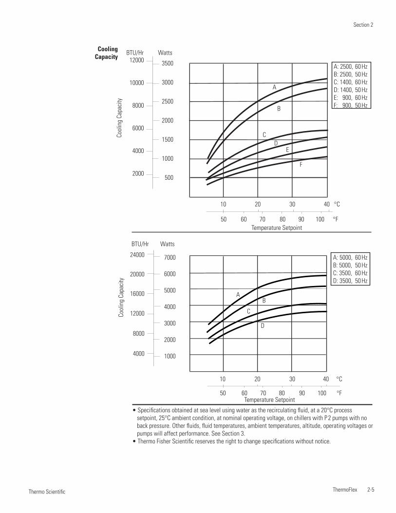
Section 2
ThermoFlex 2-5 Thermo Scientific
• Specifications obtained at sea level using water as the recirculating fluid, at a 20°C process setpoint, 25°C ambient condition, at nominal operating voltage, on chillers with P 2 pumps with no back pressure. Other fluids, fluid temperatures, ambient temperatures, altitude, operating voltages or pumps will affect performance. See Section 3.
• Thermo Fisher Scientific reserves the right to change specifications without notice.
Cooling Capacity
10 20 30 40 °C
50 60 70 80 90 100 °FTemperature Setpoint
Cool
ing
Capa
city
BTU/Hr Watts
A: 5000, 60 HzB: 5000, 50 HzC: 3500, 60 HzD: 3500, 50 Hz
AB
C
D
7000
6000
5000
4000
3000
2000
1000
24000
20000
16000
12000
8000
4000
A: 2500, 60 HzB: 2500, 50 HzC: 1400, 60 HzD: 1400, 50 HzE: 900, 60 HzF: 900, 50 Hz
A
CD
E
F
B
10 20 30 40 °C
50 60 70 80 90 100 °FTemperature Setpoint
Cool
ing
Capa
city
BTU/Hr Watts12000
10000
8000
6000
4000
2000
3500
3000
2500
2000
1500
1000
500
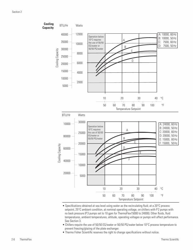
Section 2
2-6 ThermoFlex Thermo Scientific
A: 10000, 60 HzB: 10000, 50 HzC: 7500, 60 HzD: 7500, 50 Hz
A
BC
D
10 20 30 40 °C
50 60 70 80 90 100 °FTemperature Setpoint
Cool
ing
Capa
city
BTU/Hr Watts
40000
35000
30000
25000
20000
15000
10000
5000
Operation below 10°C requires the use of 50/50 EG/water or 50/50 PG/water
12000
10000
8000
6000
4000
2000
• Specifications obtained at sea level using water as the recirculating fluid, at a 20°C process setpoint, 25°C ambient condition, at nominal operating voltage, on chillers with P 2 pumps with no back pressure (P 3 pumps set to 10 gpm for ThermoFlex15000 to 24000). Other fluids, fluid temperatures, ambient temperatures, altitude, operating voltages or pumps will affect performance. See Section 3.
• Chillers require the use of 50/50 EG/water or 50/50 PG/water below 10°C process temperature to prevent freezing/glazing of the plate exchanger.
• Thermo Fisher Scientific reserves the right to change specifications without notice.
Cooling Capacity
Operation below 10°C requires the use of 50/50 EG/water or 50/50 PG/water
A: 24000, 60 HzB: 24000, 50 HzC: 20000, 60 HzD: 20000, 50 HzE: 15000, 60 HzF: 15000, 50 Hz
A
BC
DE
F
10 20 30 40 °C
50 60 70 80 90 100 °FTemperature Setpoint
Cool
ing
Capa
city
30000
25000
20000
15000
10000
5000
BTU/Hr Watts
10000
80000
60000
40000
20000
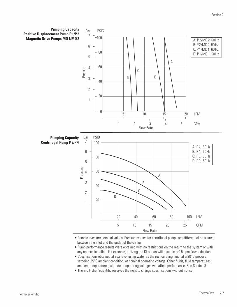
Section 2
ThermoFlex 2-7 Thermo Scientific
• Pump curves are nominal values. Pressure values for centrifugal pumps are differential pressures between the inlet and the outlet of the chiller.
• Pump performance results were obtained with no restrictions on the return to the system or with any options installed. For example, utilizing the DI option will result in a 0.5 gpm flow reduction .
• Specifications obtained at sea level using water as the recirculating fluid, at a 20°C process setpoint, 25°C ambient condition, at nominal operating voltage. Other fluids, fluid temperatures, ambient temperatures, altitude or operating voltages will affect performance. See Section 3.
• Thermo Fisher Scientific reserves the right to change specifications without notice.
Pres
sure
100
80
60
40
20
7
6
5
4
3
2
1
20 40 60 80 100 LPM
5 10 15 20 25 GPMFlow Rate
Bar PSID
A
B
CD
A: P 4, 60 HzB: P 4, 50 HzC: P 3, 60 HzD: P 3, 50 Hz
Pumping Capacity Centrifugal Pump P 3/P 4
Pumping Capacity Positive Displacement Pump P 1/P 2
Magnetic Drive Pumps MD 1/MD 2 A: P 2/MD 2, 60 HzB: P 2/MD 2, 50 HzC: P 1/MD 1, 60 HzD: P 1/MD 1, 50 Hz
5 10 15 20 LPM
1 2 3 4 5 GPM
A
B
C
D
100
80
60
40
20
0
7
6
5
4
3
2
1
Bar PSIG
Pres
sure
Flow Rate
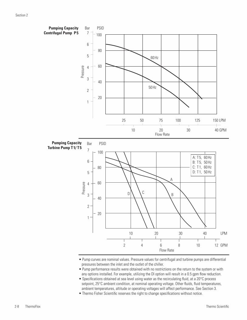
Section 2
2-8 ThermoFlex Thermo Scientific
Pumping Capacity Centrifugal Pump P 5
• Pump curves are nominal values. Pressure values for centrifugal and turbine pumps are differential pressures between the inlet and the outlet of the chiller.
• Pump performance results were obtained with no restrictions on the return to the system or with any options installed. For example, utilizing the DI option will result in a 0.5 gpm flow reduction.
• Specifications obtained at sea level using water as the recirculating fluid, at a 20°C process setpoint, 25°C ambient condition, at nominal operating voltage. Other fluids, fluid temperatures, ambient temperatures, altitude or operating voltages will affect performance. See Section 3.
• Thermo Fisher Scientific reserves the right to change specifications without notice.
25 50 75 100 125 150 LPM
10 20 30 40 GPM
60 Hz
50 Hz
100
80
60
40
20
7
6
5
4
3
2
1
Bar PSID
Pres
sure
Flow Rate
Pumping Capacity Turbine Pump T 1/ T 5
A
BCD
10 20 30 40 LPM
2 4 6 8 10 12 GPM
100
80
60
40
20
7
6
5
4
3
2
1
Bar PSID
Pres
sure
Flow Rate
A: T 5, 60 HzB: T 5, 50 HzC: T 1, 60 HzD: T 1, 50 Hz
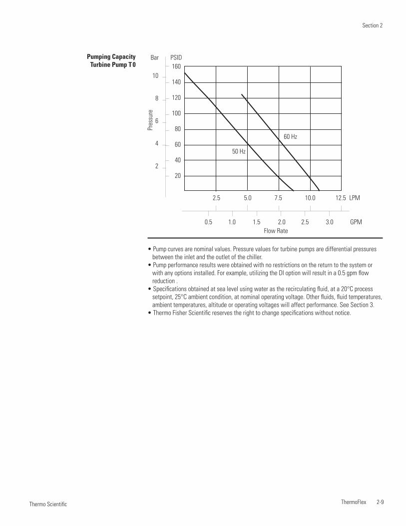
Section 2
ThermoFlex 2-9 Thermo Scientific
Pumping Capacity Turbine Pump T 0
• Pump curves are nominal values. Pressure values for turbine pumps are differential pressures between the inlet and the outlet of the chiller.
• Pump performance results were obtained with no restrictions on the return to the system or with any options installed. For example, utilizing the DI option will result in a 0.5 gpm flow reduction .
• Specifications obtained at sea level using water as the recirculating fluid, at a 20°C process setpoint, 25°C ambient condition, at nominal operating voltage. Other fluids, fluid temperatures, ambient temperatures, altitude or operating voltages will affect performance. See Section 3.
• Thermo Fisher Scientific reserves the right to change specifications without notice.
60 Hz
50 Hz
160
140
120
100
80
60
40
20
10
8
6
4
2
Bar PSID
Pres
sure
2.5 5.0 7.5 10.0 12.5 LPM
0.5 1.0 1.5 2.0 2.5 3.0 GPMFlow Rate
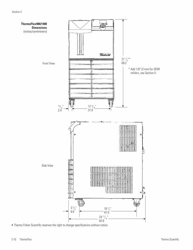
Section 2
2-10 ThermoFlex Thermo Scientific
ThermoFlex900/1400 Dimensions
(inches/centimeters)
Side View
3 3/8"8.6
18 1/2"47.0
24 11/16"62.8
Front View27 1/4"* 69.2
12 3/16"31.0
15/16"2.4
* Add 1/8" (3 mm) for SEMI chillers, see Section 5.
• Thermo Fisher Scientific reserves the right to change specifications without notice.
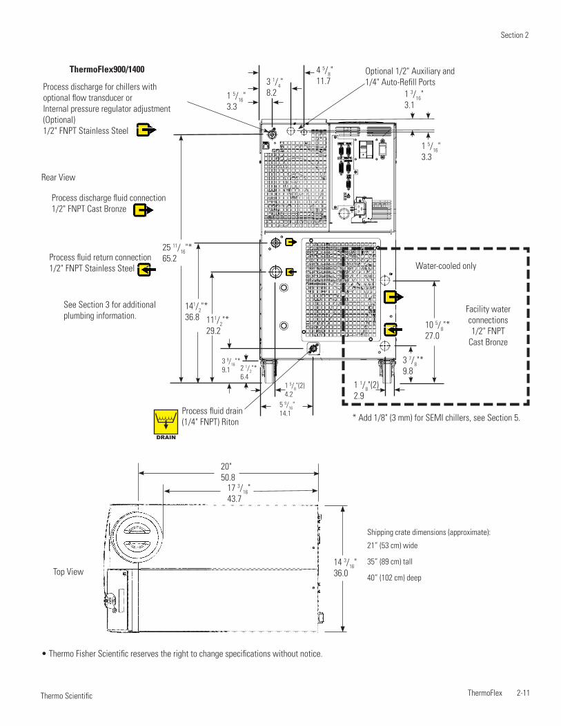
Section 2
ThermoFlex 2-11 Thermo Scientific
• Thermo Fisher Scientific reserves the right to change specifications without notice.
Top View
Shipping crate dimensions (approximate):
21” (53 cm) wide
35” (89 cm) tall
40” (102 cm) deep
17 3/16"43.7
14 3/16"36.0
20"50.8
Rear View
Water-cooled onlyProcess fluid return connection1/2" FNPT Stainless Steel
Process discharge fluid connection1/2" FNPT Cast Bronze
Facility water connections1/2" FNPT
Cast Bronze
1 5/16"3.3
1 5/8"(2)4.2
3 9/16"*9.1
3 7/8"*9.8
10 5/8"*27.0
1 1/8"(2)2.9
2 1/2"*6.4
111/2"*29.2
141/2"*36.8
25 11/16"*65.2
5 9/16"14.1
See Section 3 for additional plumbing information.
* Add 1/8" (3 mm) for SEMI chillers, see Section 5.Process fluid drain(1/4" FNPT) Riton
DRAIN
4 5/8"11.7
1 3/16"3.1
1 5/16"3.3
3 1/4"8.2
Optional 1/2" Auxiliary and 1/4" Auto-Refill Ports
ThermoFlex900/1400
Process discharge for chillers with optional flow transducer orInternal pressure regulator adjustment(Optional) 1/2" FNPT Stainless Steel
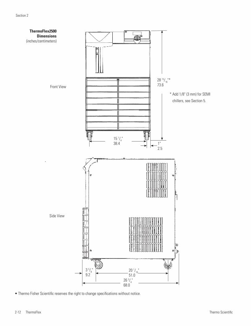
Section 2
2-12 ThermoFlex Thermo Scientific
• Thermo Fisher Scientific reserves the right to change specifications without notice.
ThermoFlex2500 Dimensions
(inches/centimeters)
Side View
3 5/8"9.2
20 1/16"51.0
Front View
28 15/16"* 73.6
15 1/4"38.4 1"
2.5
* Add 1/8" (3 mm) for SEMI
chillers, see Section 5.
26 3/4"68.0
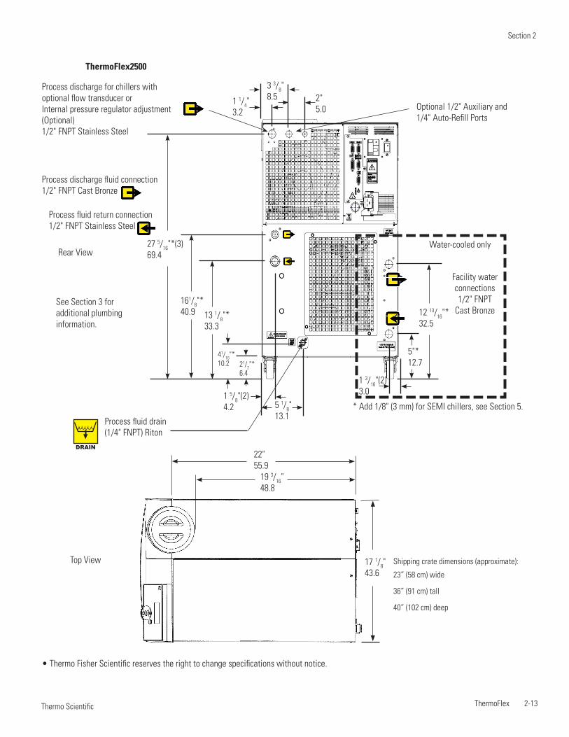
Section 2
ThermoFlex 2-13 Thermo Scientific
• Thermo Fisher Scientific reserves the right to change specifications without notice.
3 3/8"8.5
Water-cooled only
Facility water connections1/2" FNPT
Cast Bronze
1 1/4"3.2
2"5.0
1 5/8"(2)4.2
5"*12.7
12 13/16"*32.5
1 3/16"(2)3.0
41/16"*10.2
161/8"*40.9
5 1/8"13.1
13 1/8"*33.3
27 5/16"*(3)69.4
21/2"*6.4
See Section 3 for additional plumbing information.
* Add 1/8" (3 mm) for SEMI chillers, see Section 5.
DRAIN
Process fluid drain(1/4" FNPT) Riton
Process discharge fluid connection1/2" FNPT Cast Bronze
Process fluid return connection1/2" FNPT Stainless Steel
Optional 1/2" Auxiliary and 1/4" Auto-Refill Ports
Rear View
Shipping crate dimensions (approximate):
23” (58 cm) wide
36” (91 cm) tall
40” (102 cm) deep
Top View
19 3/16"48.8
17 1/8"43.6
22"55.9
ThermoFlex2500
Process discharge for chillers with optional flow transducer orInternal pressure regulator adjustment(Optional) 1/2" FNPT Stainless Steel
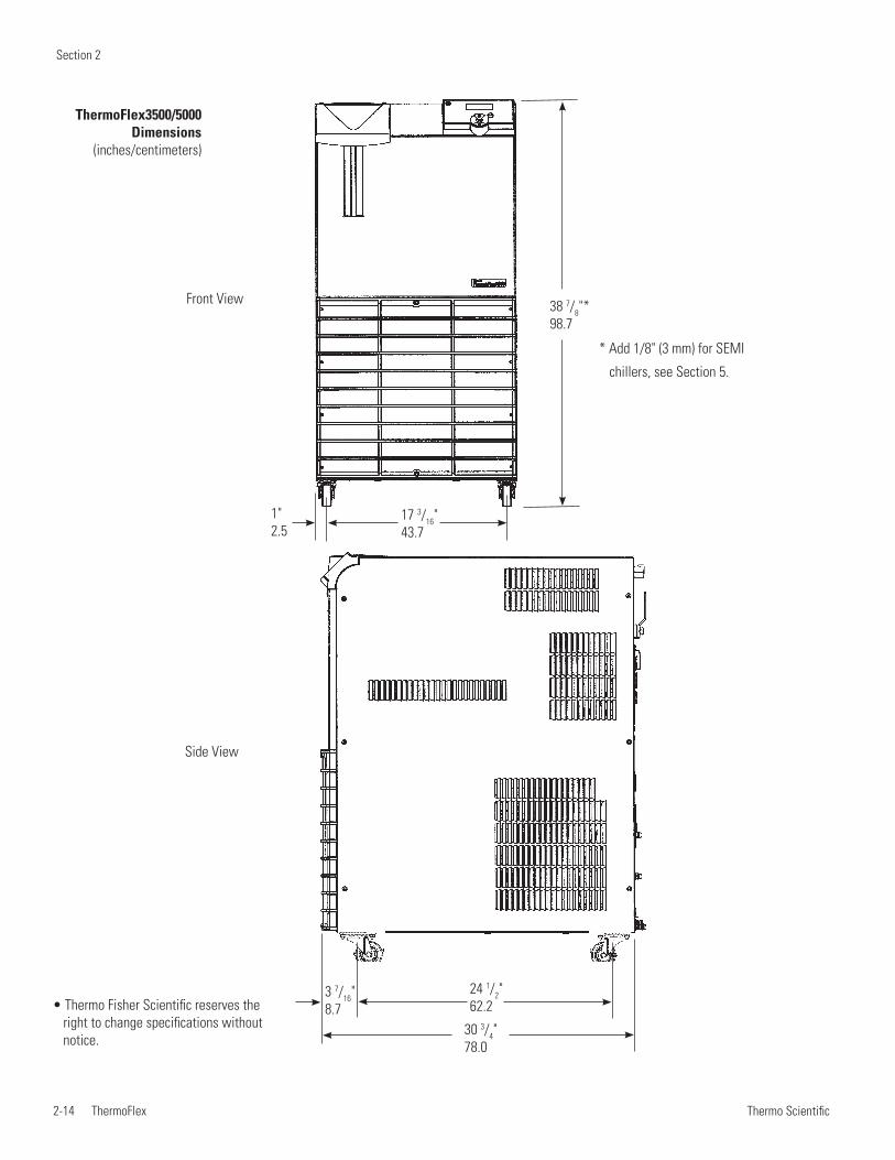
Section 2
2-14 ThermoFlex Thermo Scientific
• Thermo Fisher Scientific reserves the right to change specifications without notice.
ThermoFlex3500/5000 Dimensions
(inches/centimeters)
Side View
24 1/2"62.2
3 7/16"8.7
30 3/4"78.0
38 7/8"*98.7
1"2.5
17 3/16"43.7
Front View
* Add 1/8" (3 mm) for SEMI
chillers, see Section 5.
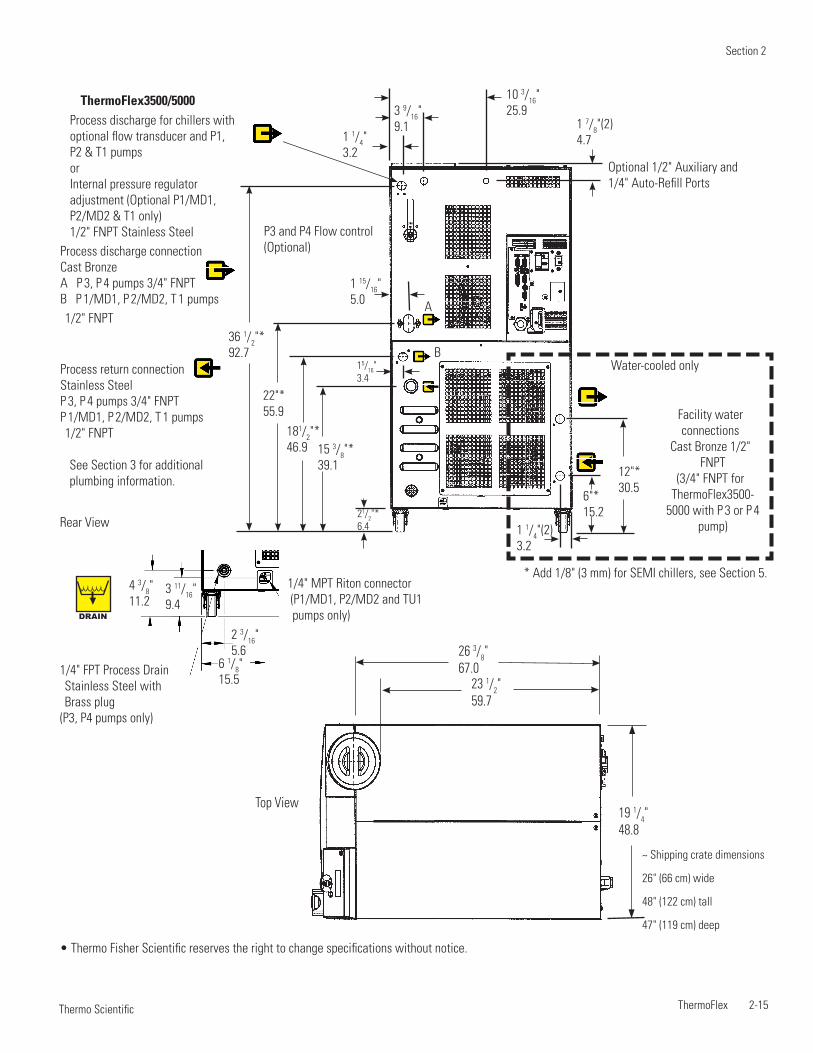
Section 2
ThermoFlex 2-15 Thermo Scientific
• Thermo Fisher Scientific reserves the right to change specifications without notice.
~ Shipping crate dimensions
26" (66 cm) wide
48" (122 cm) tall
47" (119 cm) deep
Top View
23 1/2"59.7
19 1/4"48.8
26 3/8"67.0
Rear View
Water-cooled only
Process discharge connectionCast BronzeA P 3, P 4 pumps 3/4" FNPTB P 1/MD1, P 2/MD2, T 1 pumps 1/2" FNPT
Process return connectionStainless SteelP 3, P 4 pumps 3/4" FNPTP 1/MD1, P 2/MD2, T 1 pumps 1/2" FNPT
See Section 3 for additional plumbing information.
Facility water connections
Cast Bronze 1/2" FNPT
(3/4" FNPT for ThermoFlex3500-
5000 with P 3 or P 4 pump)
1 15/16"5.0
1 1/4"3.2
1 7/8"(2)4.7
1 1/4"(2)3.2
6"*15.2
12"*30.5
15/16"3.4
15 3/8"*39.1
181/2"*46.9
22"*55.9
36 1/2"*92.7
21/2"*6.4
* Add 1/8" (3 mm) for SEMI chillers, see Section 5.
B
A
P3 and P4 Flow control (Optional)
Optional 1/2" Auxiliary and 1/4" Auto-Refill Ports
3 9/16"9.1
10 3/16"25.9
ThermoFlex3500/5000 Process discharge for chillers with optional flow transducer and P1, P2 & T1 pumpsorInternal pressure regulator adjustment (Optional P1/MD1, P2/MD2 & T1 only) 1/2" FNPT Stainless Steel
DRAIN
3 11/16"9.4
4 3/8"11.2
6 1/8"15.5
2 3/16"5.6
1/4" FPT Process Drain Stainless Steel with Brass plug
(P3, P4 pumps only)
1/4" MPT Riton connector (P1/MD1, P2/MD2 and TU1 pumps only)
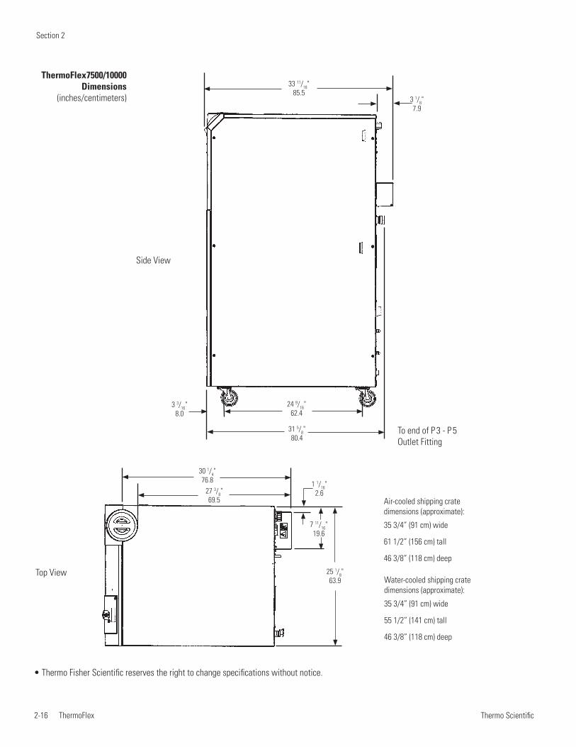
Section 2
2-16 ThermoFlex Thermo Scientific
Top View
30 1/4"76.8
27 3/8"69.5
7 11/16"19.6
1 1/16"2.6
25 1/8"63.9
• Thermo Fisher Scientific reserves the right to change specifications without notice.
ThermoFlex7500/10000 Dimensions
(inches/centimeters)
24 9/16"62.4
31 5/8"80.4
3 1/8"7.9
33 11/16"85.5
3 3/16"8.0
Side View
To end of P 3 - P 5 Outlet Fitting
Water-cooled shipping crate dimensions (approximate):
35 3/4” (91 cm) wide
55 1/2” (141 cm) tall
46 3/8” (118 cm) deep
Air-cooled shipping crate dimensions (approximate):
35 3/4” (91 cm) wide
61 1/2” (156 cm) tall
46 3/8” (118 cm) deep
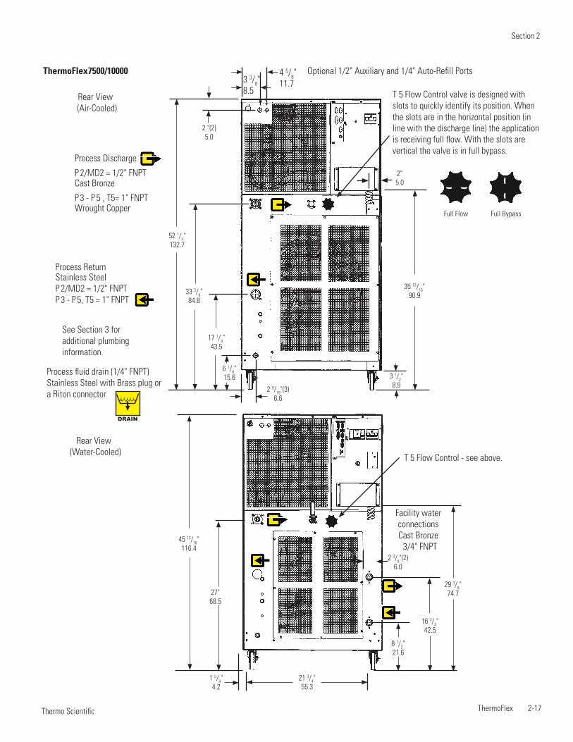
Section 2
ThermoFlex 2-17 Thermo Scientific
45 13/16"116.4
1 5/8"4.2
2 3/8"(2)6.0
21 3/4"55.3
29 3/8"74.7
16 3/4"42.5
8 1/2"21.6
27"68.5
Rear View (Water-Cooled)
Facility water connectionsCast Bronze
3/4" FNPT
6 1/8"15.6
2 9/19"(3)6.6
17 1/8"43.5
2 "(2)5.0
33 3/8"84.8
52 1/4"132.7
35 13/16"90.9
3 1/2"8.9
2"5.0
Full Flow Full Bypass
Rear View (Air-Cooled)
Optional 1/2" Auxiliary and 1/4" Auto-Refill Ports
T 5 Flow Control - see above.
See Section 3 for additional plumbing information.
Process Discharge
P 2/MD2 = 1/2" FNPTCast Bronze
P 3 - P 5 , T5= 1" FNPTWrought Copper
Process ReturnStainless Steel P 2/MD2 = 1/2" FNPTP 3 - P 5, T5 = 1" FNPT
DRAIN
Process fluid drain (1/4" FNPT)Stainless Steel with Brass plug or a Riton connector
3 3/8"8.5
4 5/8"11.7
ThermoFlex7500/10000
T 5 Flow Control valve is designed with slots to quickly identify its position. When the slots are in the horizontal position (in line with the discharge line) the application is receiving full flow. With the slots are vertical the valve is in full bypass.
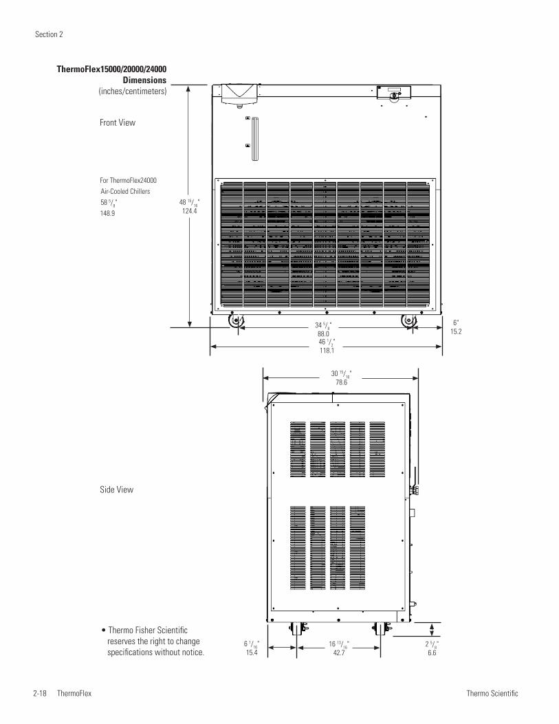
Section 2
2-18 ThermoFlex Thermo Scientific
48 15/16"124.4
6"15.2
34 5/8"88.046 1/2"118.1
30 15/16"78.6
16 13/16"42.7
2 5/8"6.6
6 1/16"15.4
ThermoFlex15000/20000/24000 Dimensions
(inches/centimeters)
Front View
Side View
For ThermoFlex24000 Air-Cooled Chillers 58 5/8"148.9
• Thermo Fisher Scientific reserves the right to change specifications without notice.
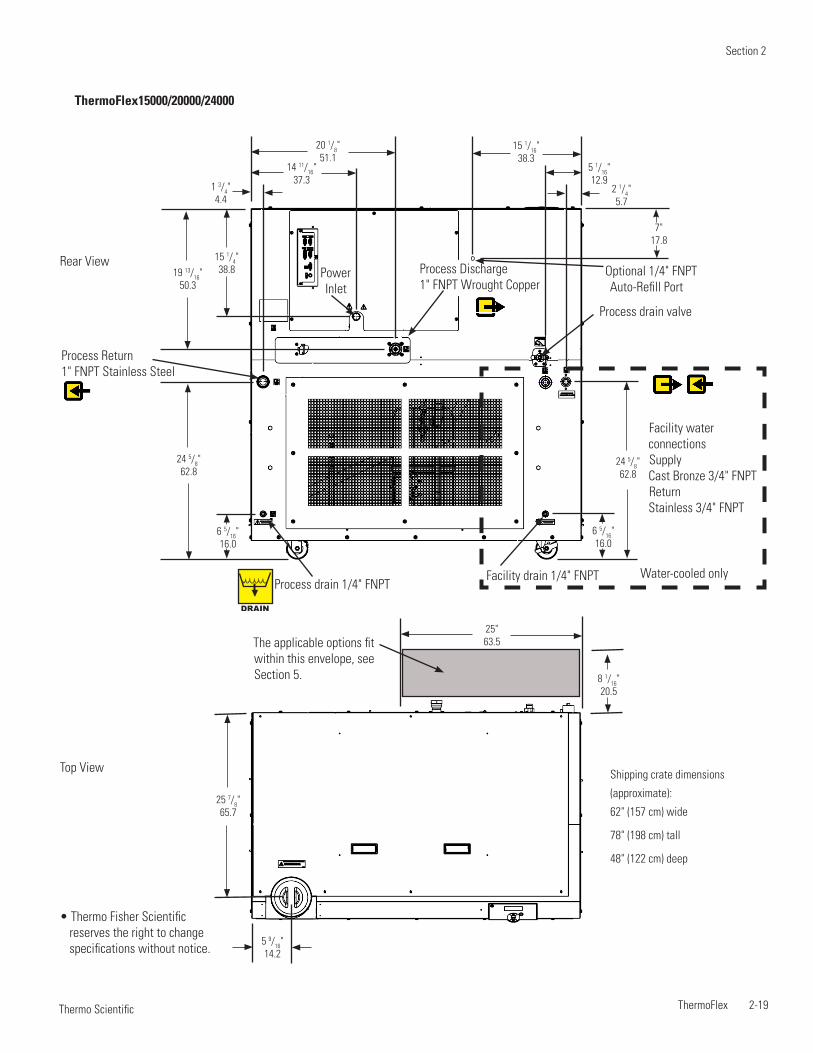
Section 2
ThermoFlex 2-19 Thermo Scientific
Shipping crate dimensions
(approximate):
62" (157 cm) wide
78" (198 cm) tall
48" (122 cm) deep
Top View
5 9/16"14.2
8 1/16"20.5
25"63.5The applicable options fit
within this envelope, see Section 5.
25 7/8"65.7
ThermoFlex15000/20000/24000
Rear View
Process Return 1" FNPT Stainless Steel
2 1/4"5.7
7"17.8
20 1/8"51.1
15 1/16"38.3
5 1/16"12.9
14 11/16"37.3
15 1/4"38.8
24 5/8"62.8
24 5/8"62.8
19 13/16"50.3
6 5/16"16.0
6 5/16"16.0
1 3/4"4.4
Facility water connectionsSupply Cast Bronze 3/4" FNPTReturn Stainless 3/4" FNPT
Facility drain 1/4" FNPTProcess drain 1/4" FNPT
Optional 1/4" FNPT Auto-Refill Port
Process drain valve
Process Discharge1" FNPT Wrought Copper
DRAIN
Water-cooled only
Power Inlet
• Thermo Fisher Scientific reserves the right to change specifications without notice.

Section 2
2-20 ThermoFlex Thermo Scientific
ThermoFlex 3-1 Thermo Scientific
Section 3 Installation
Ambient Temperature Range* 10°C to 40°C (50°F to 104°F)
Relative Humidity Range 10% to 80% (non-condensing)
Operating Altitude* Sea Level to 8000 feet (2438 meters)
Overvoltage Category II
Pollution Degree 2
Degree of Protection IP 20
Never place the chiller in a location where excessive heat, moisture, inadequate ventilation, or corrosive materials are present.
Note Refer to the nameplate information on the rear of the chiller.
Air-cooled chillers retain their full rated capacity at 20°C setpoint in ambient temperatures up to 25°C (77°F). For ambient temperatures above 25°C please de-rate the cooling capacity 3% for every 1°C above 25°C (77°F), up to a maximum ambient temperature of 40°C (104°F). Note that when operating at a process temperature lower than 20°C the de-rate percentage may increase due to additional gains from losses to ambient.
Note Depending on the setpoint and ambient temperatures, there may be a heat gain or loss through the plumbing resulting in a variation from setpoint temperature at the application inlet. Applications with large temperature variations between ambient and setpoint temperatures, and/or long plumbing lengths, may require additional insulation.
ThermoFlex2500 air-cooled chillers have a two-speed fan. Should the chiller's internal ambient temperature reach 50°C for 30 seconds, or reach 53°C, the fan speed will switch from slow speed to high speed to maintain internal temperatures within acceptable limits. When the temperature reaches 44°C or below for at least 15 minutes the speed will return to low. When in high speed the chiller's decibel level increases significantly.
Note High speed is required for the chiller to achieve its 2500 watt cooling capacity. At high-end operating conditions the fan can be set to run at high speed all the time using the controller's Setup Loop, see Section 4.
Site Requirements
*Because of the decrease in air density, maximum temperature for the air entering an air-cooled ThermoFlex is reduced by 1°C per 1,000 feet above sea level. In addition, cooling capacity is reduced 1.2% per 1,000 feet above sea level.
CAUTION
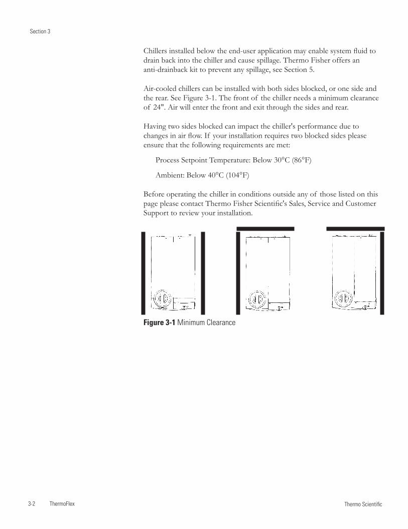
Section 3
3-2 ThermoFlex Thermo Scientific
Chillers installed below the end-user application may enable system fluid to drain back into the chiller and cause spillage. Thermo Fisher offers an anti-drainback kit to prevent any spillage, see Section 5.
Air-cooled chillers can be installed with both sides blocked, or one side and the rear. See Figure 3-1. The front of the chiller needs a minimum clearance of 24". Air will enter the front and exit through the sides and rear.
Having two sides blocked can impact the chiller's performance due to changes in air flow. If your installation requires two blocked sides please ensure that the following requirements are met:
Process Setpoint Temperature: Below 30°C (86°F)
Ambient: Below 40°C (104°F)
Before operating the chiller in conditions outside any of those listed on this page please contact Thermo Fisher Scientific's Sales, Service and Customer Support to review your installation.
Figure 3-1 Minimum Clearance
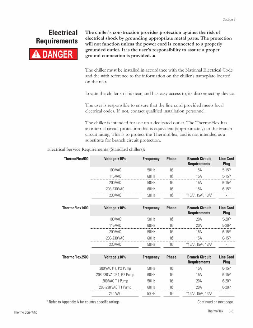
Section 3
ThermoFlex 3-3 Thermo Scientific
Electrical Requirements
The chiller's construction provides protection against the risk of electrical shock by grounding appropriate metal parts. The protection will not function unless the power cord is connected to a properly grounded outlet. It is the user's responsibility to assure a proper ground connection is provided.
The chiller must be installed in accordance with the National Electrical Code and the with reference to the information on the chiller's nameplate located on the rear.
Locate the chiller so it is near, and has easy access to, its disconnecting device.
The user is responsible to ensure that the line cord provided meets local electrical codes. If not, contact qualified installation personnel.
The chiller is intended for use on a dedicated outlet. The ThermoFlex has an internal circuit protection that is equivalent (approximately) to the branch circuit rating. This is to protect the ThermoFlex, and is not intended as a substitute for branch circuit protection.
DANGER
* Refer to Appendix A for country specific ratings. Continued on next page.
Electrical Service Requirements (Standard chillers):
ThermoFlex900 Voltage ±10% Frequency Phase Branch Circuit Requirements
Line Cord Plug
100 VAC 50 Hz 1Ø 15A 5-15P
115 VAC 60 Hz 1Ø 15A 5-15P
200 VAC 50 Hz 1Ø 15A 6-15P
208-230 VAC 60 Hz 1Ø 15A 6-15P
230 VAC 50 Hz 1Ø *16A1, 15A2, 13A3 -
ThermoFlex1400 Voltage ±10% Frequency Phase Branch Circuit Requirements
Line Cord Plug
100 VAC 50 Hz 1Ø 20A 5-20P
115 VAC 60 Hz 1Ø 20A 5-20P
200 VAC 50 Hz 1Ø 15A 6-15P
208-230 VAC 60 Hz 1Ø 15A 6-15P
230 VAC 50 Hz 1Ø *16A1, 15A2, 13A3 -
ThermoFlex2500 Voltage ±10% Frequency Phase Branch Circuit Requirements
Line Cord Plug
200 VAC P 1, P 2 Pump 50 Hz 1Ø 15A 6-15P
208-230 VAC P 1, P 2 Pump 60 Hz 1Ø 15A 6-15P
200 VAC T 1 Pump 50 Hz 1Ø 20A 6-20P
208-230 VAC T 1 Pump 60 Hz 1Ø 20A 6-20P
230 VAC 50 Hz 1Ø *16A1, 15A2, 13A3 -

Section 3
3-4 ThermoFlex Thermo Scientific
Continued on next page.
Electrical Service Requirements (Standard chillers):
ThermoFlex3500/5000 Voltage ±10% Frequency Phase Branch Circuit Requirements
Line Cord Plug
200 VAC P 1, P 2 Pump 50 Hz 1Ø 15A 6-15P
200 VAC T 1, P 3 Pump 50 Hz 1Ø 20A 6-20P
200 VAC P 4 Pump 50 Hz 1Ø 30A 6-30P
208-230 VAC P 1, P 2 Pump 60 Hz 1Ø 15A 6-15P
208-230 VAC T 1, P 3 Pump 60 Hz 1Ø 20A 6-20P
208-230 VAC P 4 Pump 60 Hz 1Ø 30A 6-30P
230 VAC P 1 - P 4 Pump 50 Hz 1Ø *16A1, 15A2, 13A3 -
ThermoFlex7500/10000(Air-cooled)
Voltage ±10% Frequency Phase MCA MOPD Line Cord Plug
200 VAC P 2 Pump 50 Hz 3Ø 16.5 30 L15-20P
200 VAC P 3 Pump 50 Hz 3Ø 18.7 30 L15-30P
200 VAC P 5 Pump 50 Hz 3Ø 22.3 35 L15-30P
200 VAC T 5 Pump 50 Hz 3Ø 17.3 30 L15-20P
208-230 VAC P 2 Pump 60 Hz 3Ø 16.5 30 L15-20P
208-230 VAC P 3 Pump 60 Hz 3Ø 18.7 30 L15-30P
208-230 VAC P 5 Pump 60 Hz 3Ø 22.3 35 L15-30P
208-230 VAC T 5 Pump 60 Hz 3Ø 17.3 30 L15-20P
400 VAC P 2 Pump 50 Hz 3Ø 10.9 20 IEC309
400 VAC P 3 Pump 50 Hz 3Ø 9.6 15 IEC309
400 VAC P 5 Pump 50 Hz 3Ø 11.8 15 IEC309
400 VAC T 5 Pump 50 Hz 3Ø 8.7 15 IEC309
ThermoFlex7500/10000(Water-cooled)
Voltage ±10% Frequency Phase MCA MOPD Line Cord Plug
200 VAC P 2 Pump 50 Hz 3Ø 16.2 30 L15-20P
200 VAC P 3 Pump 50 Hz 3Ø 18.4 30 L15-30P
200 VAC P 5 Pump 50 Hz 3Ø 22.0 35 L15-30P
200 VAC T 5 Pump 50 Hz 3Ø 17.0 30 L15-20P
208-230 VAC P 2 Pump 60 Hz 3Ø 16.2 30 L15-20P
208-230 VAC P 3 Pump 60 Hz 3Ø 18.4 30 L15-30P
208-230 VAC P 5 Pump 60 Hz 3Ø 22.0 35 L15-30P
208-230 VAC T 5 Pump 60 Hz 3Ø 17.0 30 L15-20P
400 VAC P 2 Pump 50 Hz 3Ø 10.6 20 IEC309
400 VAC P 3 Pump 50 Hz 3Ø 9.3 15 IEC309
400 VAC P 5 Pump 50 Hz 3Ø 11.5 20 IEC309
400 VAC T 5 Pump 50 Hz 3Ø 8.4 15 IEC309MCA = Minimum Current Ampacity
MOPD = Maximum Overcurrent Protective Device
Values reflect those on the nameplate located on the rear of the chiller.
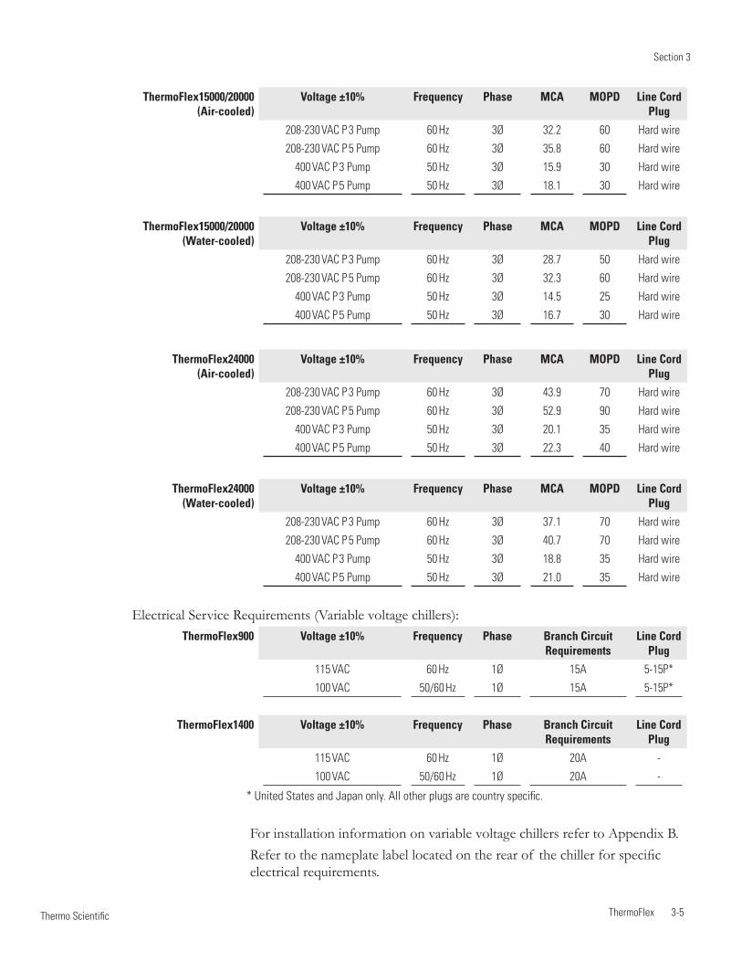
Section 3
ThermoFlex 3-5 Thermo Scientific
ThermoFlex15000/20000(Air-cooled)
Voltage ±10% Frequency Phase MCA MOPD Line Cord Plug
208-230 VAC P 3 Pump 60 Hz 3Ø 32.2 60 Hard wire
208-230 VAC P 5 Pump 60 Hz 3Ø 35.8 60 Hard wire
400 VAC P 3 Pump 50 Hz 3Ø 15.9 30 Hard wire
400 VAC P 5 Pump 50 Hz 3Ø 18.1 30 Hard wire
ThermoFlex15000/20000(Water-cooled)
Voltage ±10% Frequency Phase MCA MOPD Line Cord Plug
208-230 VAC P 3 Pump 60 Hz 3Ø 28.7 50 Hard wire
208-230 VAC P 5 Pump 60 Hz 3Ø 32.3 60 Hard wire
400 VAC P 3 Pump 50 Hz 3Ø 14.5 25 Hard wire
400 VAC P 5 Pump 50 Hz 3Ø 16.7 30 Hard wire
ThermoFlex24000(Air-cooled)
Voltage ±10% Frequency Phase MCA MOPD Line Cord Plug
208-230 VAC P 3 Pump 60 Hz 3Ø 43.9 70 Hard wire
208-230 VAC P 5 Pump 60 Hz 3Ø 52.9 90 Hard wire
400 VAC P 3 Pump 50 Hz 3Ø 20.1 35 Hard wire
400 VAC P 5 Pump 50 Hz 3Ø 22.3 40 Hard wire
ThermoFlex24000(Water-cooled)
Voltage ±10% Frequency Phase MCA MOPD Line Cord Plug
208-230 VAC P 3 Pump 60 Hz 3Ø 37.1 70 Hard wire
208-230 VAC P 5 Pump 60 Hz 3Ø 40.7 70 Hard wire
400 VAC P 3 Pump 50 Hz 3Ø 18.8 35 Hard wire
400 VAC P 5 Pump 50 Hz 3Ø 21.0 35 Hard wire
For installation information on variable voltage chillers refer to Appendix B.Refer to the nameplate label located on the rear of the chiller for specific electrical requirements.
* United States and Japan only. All other plugs are country specific.
ThermoFlex900 Voltage ±10% Frequency Phase Branch Circuit Requirements
Line Cord Plug
115 VAC 60 Hz 1Ø 15A 5-15P*
100 VAC 50/60 Hz 1Ø 15A 5-15P*
ThermoFlex1400 Voltage ±10% Frequency Phase Branch Circuit Requirements
Line Cord Plug
115 VAC 60 Hz 1Ø 20A -
100 VAC 50/60 Hz 1Ø 20A -
Electrical Service Requirements (Variable voltage chillers):
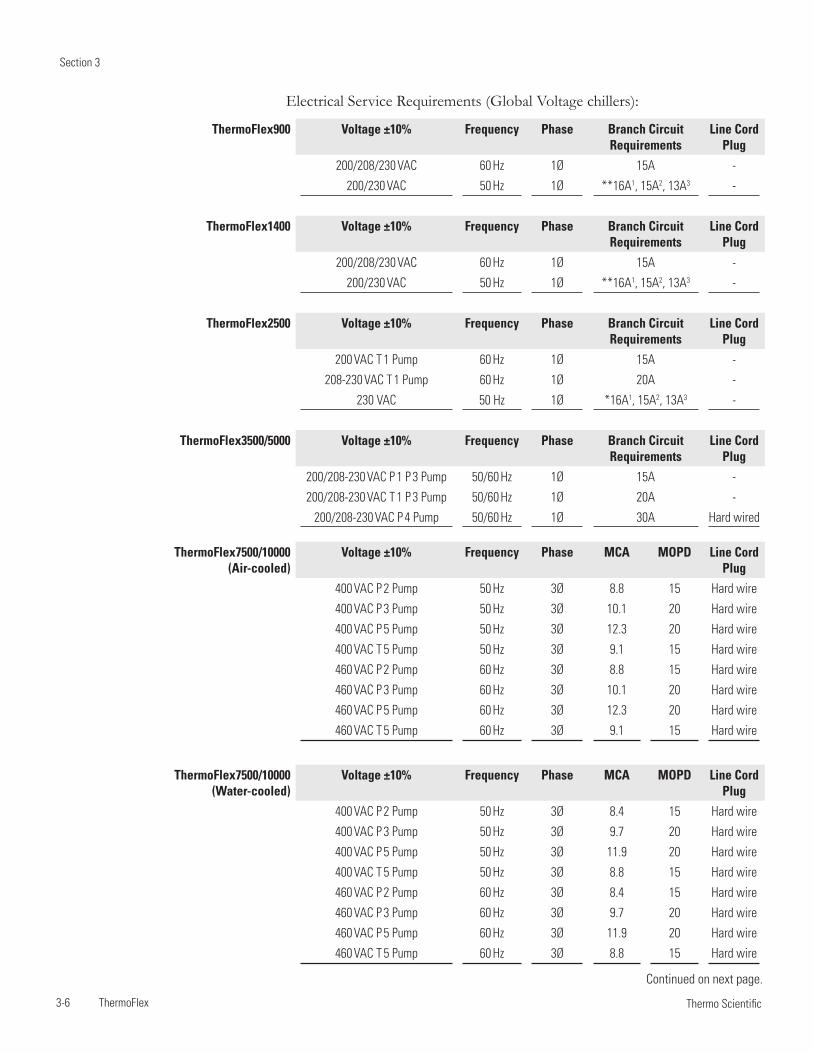
Section 3
3-6 ThermoFlex Thermo Scientific
ThermoFlex900 Voltage ±10% Frequency Phase Branch Circuit Requirements
Line Cord Plug
200/208/230 VAC 60 Hz 1Ø 15A -
200/230 VAC 50 Hz 1Ø **16A1, 15A2, 13A3 -
ThermoFlex1400 Voltage ±10% Frequency Phase Branch Circuit Requirements
Line Cord Plug
200/208/230 VAC 60 Hz 1Ø 15A -
200/230 VAC 50 Hz 1Ø **16A1, 15A2, 13A3 -
ThermoFlex2500 Voltage ±10% Frequency Phase Branch Circuit Requirements
Line Cord Plug
200 VAC T 1 Pump 60 Hz 1Ø 15A -
208-230 VAC T 1 Pump 60 Hz 1Ø 20A -
230 VAC 50 Hz 1Ø *16A1, 15A2, 13A3 -
ThermoFlex3500/5000 Voltage ±10% Frequency Phase Branch Circuit Requirements
Line Cord Plug
200/208-230 VAC P 1 P 3 Pump 50/60 Hz 1Ø 15A -
200/208-230 VAC T 1 P 3 Pump 50/60 Hz 1Ø 20A -
200/208-230 VAC P 4 Pump 50/60 Hz 1Ø 30A Hard wired
Electrical Service Requirements (Global Voltage chillers):
ThermoFlex7500/10000(Air-cooled)
Voltage ±10% Frequency Phase MCA MOPD Line Cord Plug
400 VAC P 2 Pump 50 Hz 3Ø 8.8 15 Hard wire
400 VAC P 3 Pump 50 Hz 3Ø 10.1 20 Hard wire
400 VAC P 5 Pump 50 Hz 3Ø 12.3 20 Hard wire
400 VAC T 5 Pump 50 Hz 3Ø 9.1 15 Hard wire
460 VAC P 2 Pump 60 Hz 3Ø 8.8 15 Hard wire
460 VAC P 3 Pump 60 Hz 3Ø 10.1 20 Hard wire
460 VAC P 5 Pump 60 Hz 3Ø 12.3 20 Hard wire
460 VAC T 5 Pump 60 Hz 3Ø 9.1 15 Hard wire
ThermoFlex7500/10000(Water-cooled)
Voltage ±10% Frequency Phase MCA MOPD Line Cord Plug
400 VAC P 2 Pump 50 Hz 3Ø 8.4 15 Hard wire
400 VAC P 3 Pump 50 Hz 3Ø 9.7 20 Hard wire
400 VAC P 5 Pump 50 Hz 3Ø 11.9 20 Hard wire
400 VAC T 5 Pump 50 Hz 3Ø 8.8 15 Hard wire
460 VAC P 2 Pump 60 Hz 3Ø 8.4 15 Hard wire
460 VAC P 3 Pump 60 Hz 3Ø 9.7 20 Hard wire
460 VAC P 5 Pump 60 Hz 3Ø 11.9 20 Hard wire
460 VAC T 5 Pump 60 Hz 3Ø 8.8 15 Hard wire
Continued on next page.
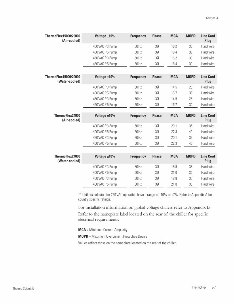
Section 3
ThermoFlex 3-7 Thermo Scientific
** Chillers selected for 230 VAC operation have a range of -10% to +7%. Refer to Appendix A for country specific ratings.
For installation information on global voltage chillers refer to Appendix B.Refer to the nameplate label located on the rear of the chiller for specific electrical requirements.
ThermoFlex15000/20000(Air-cooled)
Voltage ±10% Frequency Phase MCA MOPD Line Cord Plug
400 VAC P 3 Pump 50 Hz 3Ø 16.2 30 Hard wire
400 VAC P 5 Pump 50 Hz 3Ø 18.4 30 Hard wire
460 VAC P 3 Pump 60 Hz 3Ø 16.2 30 Hard wire
460 VAC P 5 Pump 60 Hz 3Ø 18.4 30 Hard wire
ThermoFlex15000/20000(Water-cooled)
Voltage ±10% Frequency Phase MCA MOPD Line Cord Plug
400 VAC P 3 Pump 50 Hz 3Ø 14.5 25 Hard wire
400 VAC P 5 Pump 50 Hz 3Ø 16.7 30 Hard wire
460 VAC P 3 Pump 60 Hz 3Ø 14.5 25 Hard wire
460 VAC P 5 Pump 60 Hz 3Ø 16.7 30 Hard wire
ThermoFlex24000(Air-cooled)
Voltage ±10% Frequency Phase MCA MOPD Line Cord Plug
400 VAC P 3 Pump 50 Hz 3Ø 20.1 35 Hard wire
400 VAC P 5 Pump 50 Hz 3Ø 22.3 40 Hard wire
460 VAC P 3 Pump 60 Hz 3Ø 20.1 35 Hard wire
460 VAC P 5 Pump 60 Hz 3Ø 22.3 40 Hard wire
ThermoFlex24000(Water-cooled)
Voltage ±10% Frequency Phase MCA MOPD Line Cord Plug
400 VAC P 3 Pump 50 Hz 3Ø 18.8 35 Hard wire
400 VAC P 5 Pump 50 Hz 3Ø 21.0 35 Hard wire
460 VAC P 3 Pump 60 Hz 3Ø 18.8 35 Hard wire
460 VAC P 5 Pump 60 Hz 3Ø 21.0 35 Hard wire
MCA = Minimum Current Ampacity
MOPD = Maximum Overcurrent Protective Device
Values reflect those on the nameplate located on the rear of the chiller .
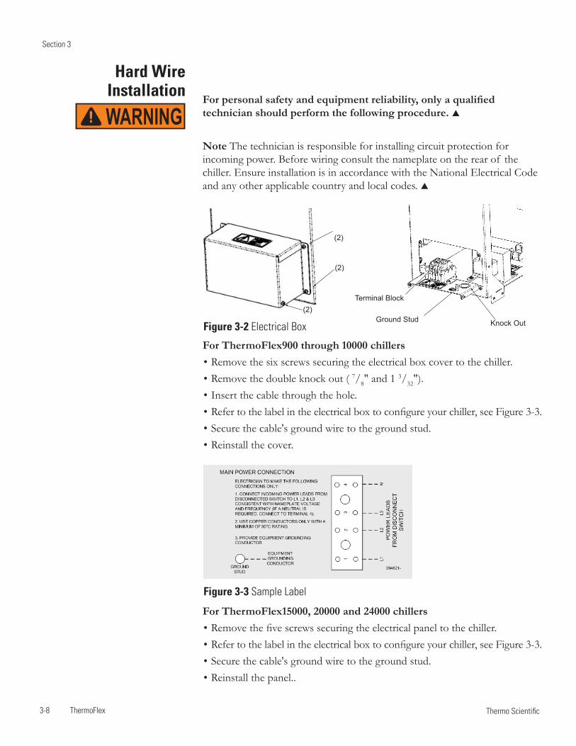
Section 3
3-8 ThermoFlex Thermo Scientific
Hard Wire Installation For personal safety and equipment reliability, only a qualified
technician should perform the following procedure.
Note The technician is responsible for installing circuit protection for incoming power. Before wiring consult the nameplate on the rear of the chiller. Ensure installation is in accordance with the National Electrical Code and any other applicable country and local codes.
For ThermoFlex900 through 10000 chillers• Remove the six screws securing the electrical box cover to the chiller.• Remove the double knock out ( 7/8" and 1 3/32").• Insert the cable through the hole.• Refer to the label in the electrical box to configure your chiller, see Figure 3-3.• Secure the cable's ground wire to the ground stud.• Reinstall the cover.
For ThermoFlex15000, 20000 and 24000 chillers • Remove the five screws securing the electrical panel to the chiller.• Refer to the label in the electrical box to configure your chiller, see Figure 3-3.• Secure the cable's ground wire to the ground stud.• Reinstall the panel..
(2)
Terminal Block
Ground Stud Knock Out
(2)
(2)
Figure 3-2 Electrical Box
Figure 3-3 Sample Label
WARNING
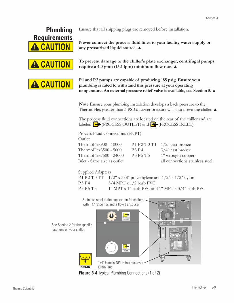
Section 3
ThermoFlex 3-9 Thermo Scientific
Plumbing Requirements
Ensure that all shipping plugs are removed before installation.
Never connect the process fluid lines to your facility water supply or any pressurized liquid source.
To prevent damage to the chiller's plate exchanger, centrifugal pumps require a 4.0 gpm (15.1 lpm) minimum flow rate.
P 1 and P 2 pumps are capable of producing 185 psig. Ensure your plumbing is rated to withstand this pressure at your operating temperature. An external pressure relief valve is available, see Section 5.
Note Ensure your plumbing installation develops a back pressure to the ThermoFlex greater than 3 PSIG. Lower pressure will shut down the chiller.
The process fluid connections are located on the rear of the chiller and are labeled (PROCESS OUTLET) and (PROCESS INLET).
Process Fluid Connections (FNPT)Outlet ThermoFlex900 - 10000 P 1 P 2 T 0 T 1 1/2" cast bronzeThermoFlex3500 - 5000 P 3 P 4 3/4" cast bronzeThermoFlex7500 - 24000 P 3 P 5 T 5 1" wrought copperInlet - Same size as outlet all connections stainless steel
Supplied AdaptersP 1 P 2 T 0 T 1 1/2" x 3/8'' polyethylene and 1/2" x 1/2" nylon P 3 P 4 3/4 MPT x 1/2 barb PVCP 3 P 5 T 5 1" MPT x 1" barb PVC and 1" MPT x 3/4" barb PVC
CAUTION
CAUTION
CAUTION
1/4" Female NPT Riton Reservoir Drain Plug
See Section 2 for the specific locations on your chiller.
Figure 3-4 Typical Plumbing Connections (1 of 2)DRAIN
Stainless steel outlet connection for chillers with P 1/P 2 pumps and a flow transducer
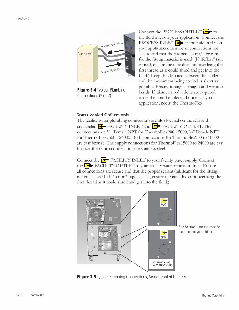
Section 3
3-10 ThermoFlex Thermo Scientific
Water-cooled Chillers only The facility water plumbing connections are also located on the rear and are labeled FACILITY INLET and FACILITY OUTLET. The connections are ½" Female NPT for ThermoFlex900 - 5000, ¾" Female NPT for ThermoFlex7500 - 24000. Both connections for ThermoFlex900 to 10000 are cast bronze. The supply connections for ThermoFlex15000 to 24000 are cast bronze, the return connections are stainless steel.
Connect the FACILITY INLET to your facility water supply. Connect the FACILITY OUTLET to your facility water return or drain. Ensure all connections are secure and that the proper sealant/lubricant for the fitting material is used. (If Teflon® tape is used, ensure the tape does not overhang the first thread as it could shred and get into the fluid.)
Connect the PROCESS OUTLET to the fluid inlet on your application. Connect the PROCESS INLET to the fluid outlet on your application. Ensure all connections are secure and that the proper sealant/lubricant for the fitting material is used. (If Teflon® tape is used, ensure the tape does not overhang the first thread as it could shred and get into the fluid.) Keep the distance between the chiller and the instrument being cooled as short as possible. Ensure tubing is straight and without bends. If diameter reductions are required, make them at the inlet and outlet of your application, not at the ThermoFlex.
Figure 3-4 Typical Plumbing Connections (2 of 2)
Process Fluid Flow
Process Fluid Flow
Application
Figure 3-5 Typical Plumbing Connections, Water-cooled Chillers
See Section 2 for the specific locations on your chiller.
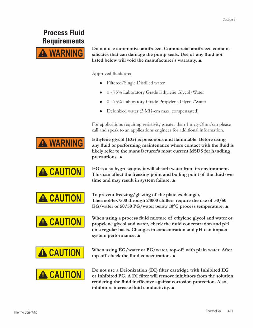
Section 3
ThermoFlex 3-11 Thermo Scientific
Process Fluid Requirements
Do not use automotive antifreeze. Commercial antifreeze contains silicates that can damage the pump seals. Use of any fluid not listed below will void the manufacturer’s warranty.
Approved fluids are:
Filtered/Single Distilled water
0 - 75% Laboratory Grade Ethylene Glycol/Water
0 - 75% Laboratory Grade Propylene Glycol/Water
Deionized water (3 MΩ-cm max, compensated)
For applications requiring resistivity greater than 1 meg-Ohm/cm please call and speak to an applications engineer for additional information.
Ethylene glycol (EG) is poisonous and flammable. Before using any fluid or performing maintenance where contact with the fluid is likely refer to the manufacturer’s most current MSDS for handling precautions.
EG is also hygroscopic, it will absorb water from its environment. This can affect the freezing point and boiling point of the fluid over time and may result in system failure.
To prevent freezing/glazing of the plate exchanger, ThermoFlex7500 through 24000 chillers require the use of 50/50 EG/water or 50/50 PG/water below 10°C process temperature.
When using a process fluid mixture of ethylene glycol and water or propylene glycol and water, check the fluid concentration and pH on a regular basis. Changes in concentration and pH can impact system performance.
When using EG/water or PG/water, top-off with plain water. After top-off check the fluid concentration.
Do not use a Deionization (DI) filter cartridge with Inhibited EG or Inhibited PG. A DI filter will remove inhibitors from the solution rendering the fluid ineffective against corrosion protection. Also, inhibitors increase fluid conductivity.
WARNING
WARNING
CAUTION
CAUTION
CAUTION
CAUTION
CAUTION
Section 3
3-12 ThermoFlex Thermo Scientific
Compatibility with Approved
Fluids
Filtered/Single Distilled Water Filtered drinking water and single distilled water are good choices for recirculating chillers because the filtering/distilling process used removes microorganisms that could create biological fouling as well as harmful particulates and excessive minerals that could cause deposits and scaling.
Chlorine Short term usage of tap water may not cause any adverse affects on the chiller or your application, but in the long term problems may arise. To help alleviate these problems Thermo Fisher Scientific recommends the use of chlorine.
The duration of time that chlorine remains in solution depends on factors such as water temperature, pH and availability of direct sunlight. We recommend maintaining chlorine levels at proper levels using chlorine test strips, generally 1 to 5 ppm is adequate.
For best results, maintain the pH of the fluid between 6.5 and 7.5. Do not add additional chlorine without first determining the concentration ratio that already exists in the fluid supply. Corrosion and degradation of the circulation components can result from concentration ratios that are too high. Contact our customer support for additional information.
Deionized Water Deionized water is water that has had its mineral ions removed using ion exchange resins. The purpose of this process is to remove the ions that allow electrical current to flow more easily through water. This helps to prevent electrical leaks to ground through the recirculating fluid. Deionized water is classified by the electrical resistance of the water, usually measured in MΩ-cm, with pure water having a resistance of 18 MΩ-cm.
Deionized water is in an unbalanced state and will leach the missing ions from the materials it comes in contact with. The aggressive nature of this leaching can cause pitting on metal surfaces. Note that the deionizing process does not remove microorganisms. Because of this, we recommend deionized water only with applications that have it as a specified requirement.
In any case, only deionized water with 3 MΩ-cm resistivity maximum is approved for use in Thermo Fisher Scientific recirculating chillers.
Recommended Biocides and Inhibitors Thermo Fisher Scientific offers a biocide and inhibitor package Thermo 200 (Nalco) premixed with 5 gallons of water or as a kit to be added to water. No other biocide or inhibitor is recommended for use in our recirculating chillers.
Biocides are corrosive and can cause irreversible eye damage and skin burns. They are harmful if inhaled, swallowed or absorbed through the skin. Refer to the manufacturer's most current MSDS. WARNING
Section 3
ThermoFlex 3-13 Thermo Scientific
To prevent freezing/glazing of the plate exchanger, ThermoFlex7500 through 24000 chillers require the use of 50/50 EG/water or 50/50 PG/water below 10°C process temperature.
Uninhibited Ethylene Glycol/Water Ethylene glycol is used to depress the freezing point of water and should only be used at temperatures where freeze point suppression is required. Ethylene glycol does not improve heat transfer and is not recommended for use as a biocide. Because glycols lower the surface tension of water and do not evaporate as readily as water, they may cause visible weepage past the pump seals. If weepage cannot be tolerated, seal-less, use magnetically driven pumps where available.
Uninhibited simply means that the glycol does not contain any additives to prevent corrosion. While uninhibited ethylene glycol is acceptable for use, the pH level must be closely monitored and the fluid may need to be replaced more often. Since all glycols produce acids in the presence of air and the fluid, change the glycol if the pH falls below 8. Note that litmus paper will not work to test the pH of ethylene glycol/water.
Inhibited Ethylene Glycol/Water and Inhibited Propylene Glycol/Water Inhibited glycol can help protect the wetted metals within the cooling circuit from corrosion caused by poor water quality, ethylene glycol oxidation (low pH) and mixed metals (electrolysis). The inhibitor works by either leaving a barrier coating on metal surfaces to buffer them from the corrosive fluid or by creating an oxidized layer that protects the underlying metal (passivating).
Inhibited automotive glycols are never acceptable. They use either silicates or Organic Acid Technology (OAT) as the inhibitor and these components are not compatible with the polymers used in recirculating chillers including the pump seals and internal hoses.
Inhibitors may also accelerate pump seal wear and seal-less, Use magnetically driven pumps where available.
Uninhibited Propylene Glycol/Water Propylene glycol does not transfer heat as well as ethylene glycol, but can be used when freeze point suppression is required as well as lower toxicity.
Propylene glycol does not function as a biocide and the pH needs to be maintained the same as with ethylene glycol as it also produces acid when oxidized.
CAUTION
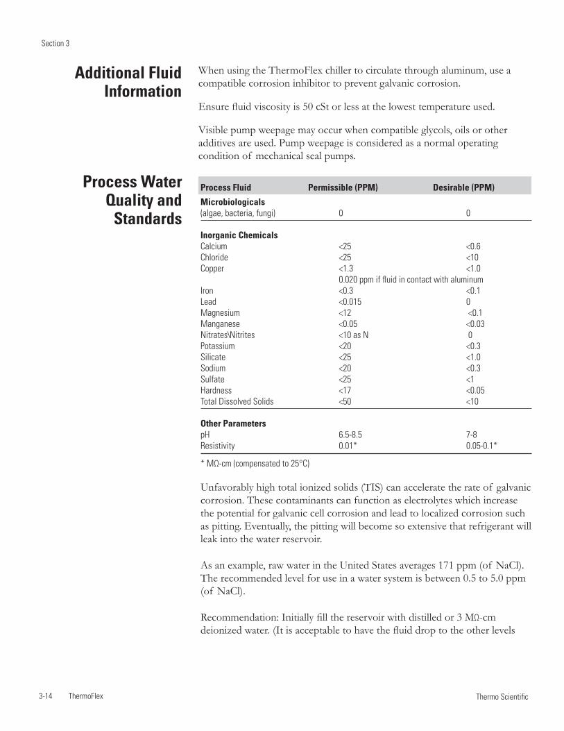
Section 3
3-14 ThermoFlex Thermo Scientific
Process Fluid Permissible (PPM) Desirable (PPM)
Microbiologicals (algae, bacteria, fungi) 0 0
Inorganic ChemicalsCalcium <25 <0.6Chloride <25 <10 Copper <1.3 <1.0 0.020 ppm if fluid in contact with aluminumIron <0.3 <0.1Lead <0.015 0Magnesium <12 <0.1Manganese <0.05 <0.03Nitrates\Nitrites <10 as N 0Potassium <20 <0.3Silicate <25 <1.0Sodium <20 <0.3Sulfate <25 <1Hardness <17 <0.05Total Dissolved Solids <50 <10
Other ParameterspH 6.5-8.5 7-8Resistivity 0.01* 0.05-0.1*
* MΩ-cm (compensated to 25°C)
Unfavorably high total ionized solids (TIS) can accelerate the rate of galvanic corrosion. These contaminants can function as electrolytes which increase the potential for galvanic cell corrosion and lead to localized corrosion such as pitting. Eventually, the pitting will become so extensive that refrigerant will leak into the water reservoir.
As an example, raw water in the United States averages 171 ppm (of NaCl). The recommended level for use in a water system is between 0.5 to 5.0 ppm (of NaCl).
Recommendation: Initially fill the reservoir with distilled or 3 MΩ-cm deionized water. (It is acceptable to have the fluid drop to the other levels
Process Water Quality and
Standards
When using the ThermoFlex chiller to circulate through aluminum, use a compatible corrosion inhibitor to prevent galvanic corrosion.
Ensure fluid viscosity is 50 cSt or less at the lowest temperature used.
Visible pump weepage may occur when compatible glycols, oils or other additives are used. Pump weepage is considered as a normal operating condition of mechanical seal pumps.
Additional Fluid Information
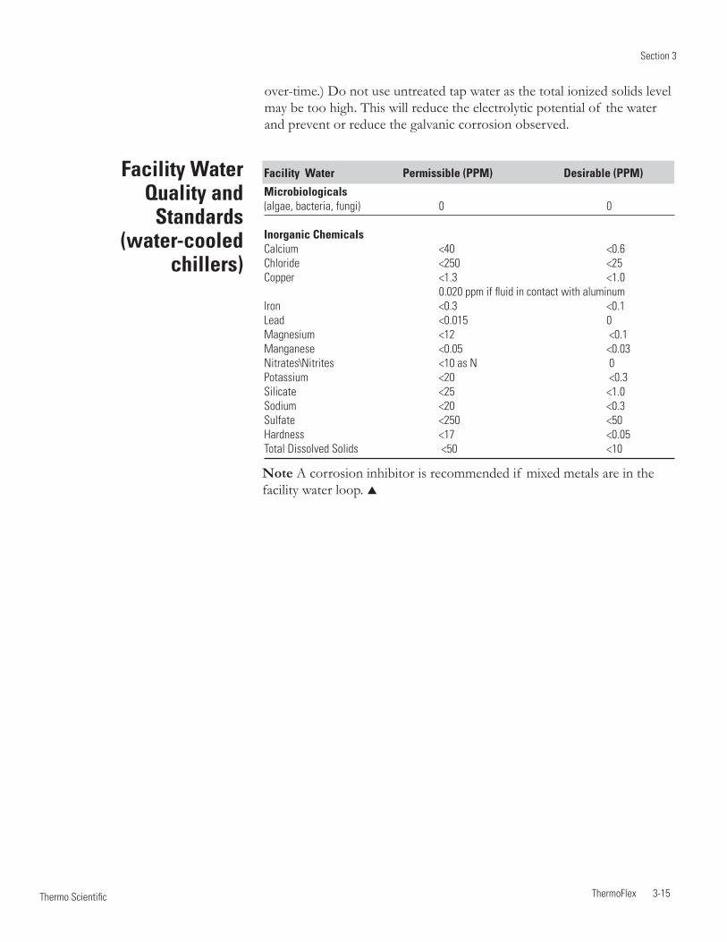
Section 3
ThermoFlex 3-15 Thermo Scientific
Facility Water Quality and
Standards (water-cooled
chillers)
Facility Water Permissible (PPM) Desirable (PPM)
Microbiologicals (algae, bacteria, fungi) 0 0
Inorganic ChemicalsCalcium <40 <0.6Chloride <250 <25 Copper <1.3 <1.0 0.020 ppm if fluid in contact with aluminumIron <0.3 <0.1Lead <0.015 0Magnesium <12 <0.1Manganese <0.05 <0.03Nitrates\Nitrites <10 as N 0Potassium <20 <0.3Silicate <25 <1.0Sodium <20 <0.3Sulfate <250 <50Hardness <17 <0.05Total Dissolved Solids <50 <10
Note A corrosion inhibitor is recommended if mixed metals are in the facility water loop.
over-time.) Do not use untreated tap water as the total ionized solids level may be too high. This will reduce the electrolytic potential of the water and prevent or reduce the galvanic corrosion observed.
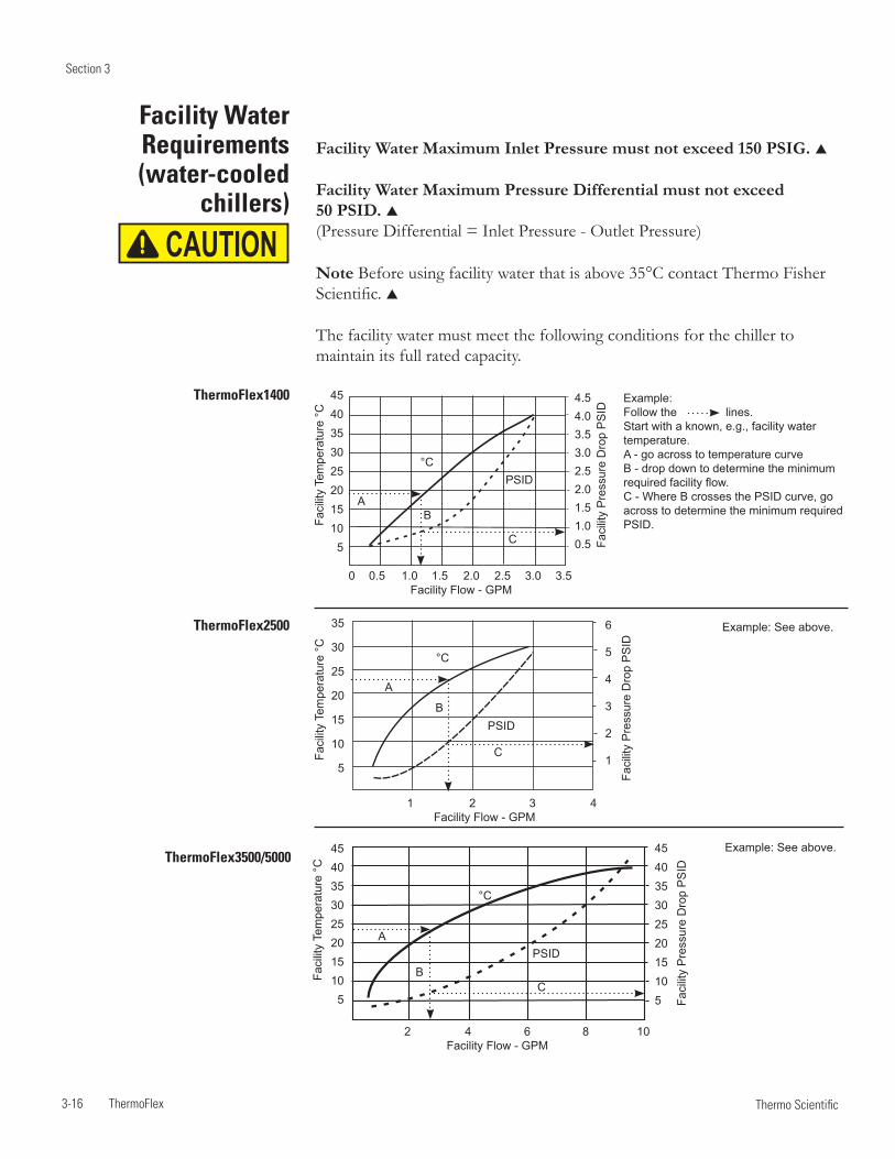
Section 3
3-16 ThermoFlex Thermo Scientific
Facility Water Maximum Inlet Pressure must not exceed 150 PSIG.
Facility Water Maximum Pressure Differential must not exceed 50 PSID. (Pressure Differential = Inlet Pressure - Outlet Pressure)
Note Before using facility water that is above 35°C contact Thermo Fisher Scientific.
The facility water must meet the following conditions for the chiller to maintain its full rated capacity.
Facility Water Requirements (water-cooled
chillers)
Faci
lity
Pre
ssur
e D
rop
PS
ID
0 0.5 1.0 1.5 2.0 2.5 3.0 3.5 Facility Flow - GPM
Faci
lity
Tem
pera
ture
°C
45403530252015105
4.54.03.53.02.52.01.51.00.5
°CPSID
ThermoFlex1400 Example:Follow the lines.Start with a known, e.g., facility water temperature.A - go across to temperature curveB - drop down to determine the minimum required facility flow.C - Where B crosses the PSID curve, go across to determine the minimum required PSID.
AB
C
Faci
lity
Tem
pera
ture
°C
45403530252015105
2 4 6 8 10 Facility Flow - GPM
Faci
lity
Pre
ssur
e D
rop
PS
ID
45403530252015105
°C
PSID
ThermoFlex3500/5000
A
BC
Example: See above.
Faci
lity
Pre
ssur
e D
rop
PS
ID
1 2 3 4 Facility Flow - GPM
Faci
lity
Tem
pera
ture
°C
35
30
25
20
15
10
5
6
5
4
3
2
1
°C
PSID
ThermoFlex2500
A
B
C
Example: See above.
CAUTION

Section 3
ThermoFlex 3-17 Thermo Scientific
ThermoFlex24000
Beispiel:Folgen Sie den gepunkteten Pfeillinien.Beginnen Sie mit einer bekannten Größe, z. B. mit der Kühlwassertemperatur.A – Ermitteln Sie den Schnittpunkt mit der Temperaturkurve.B – Ermitteln Sie auf der horizontalen Achse den zugehörigen minimal erforderlichen Kühlwasserfluss.C – Gehen Sie vom Schnittpunkt der Linie B mit der PSID-Kurve zur rechten vertikalen Achse, um den minimal erforderlichen Druckabfall in psid zu ermitteln.
ThermoFlex15000/20000
Beispiel: Siehe die Erläute-rungen unten.
ThermoFlex7500/10000
Beispiel: Siehe die Erläuterun-gen unten.
Küh
lwas
serte
mpe
ratu
r °C
40
35
30
25
20
15
10
5
Küh
lwas
serd
ruck
abfa
ll ps
id
30
25
20
15
10
5
PSIDA
B
C
°C
Küh
lwas
serte
mpe
ratu
r °C
40
35
30
25
20
15
10
5
5 10 15 20 25 30 Kühlwasserdurchfluss, gal./min
5 10 15 20 25 30 Kühlwasserdurchfluss, gal./min
Küh
lwas
serd
ruck
abfa
ll ps
id
60
50
40
30
20
10
PSID
A
B
C
°C
Küh
lwas
serd
ruck
abfa
ll ps
id
5 10 15 Kühlwasserdurchfluss, gal./min
°C
PSID
A
B
C
Küh
lwas
serte
mpe
ratu
r °C
40
35
30
25
20
15
10
5
30
25
20
15
10
5
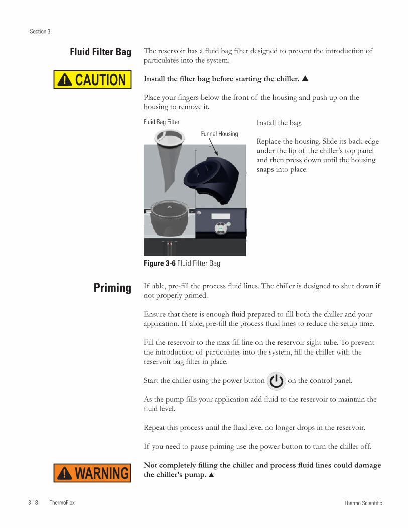
Section 3
3-18 ThermoFlex Thermo Scientific
Priming
WARNING
If able, pre-fill the process fluid lines. The chiller is designed to shut down if not properly primed.
Ensure that there is enough fluid prepared to fill both the chiller and your application. If able, pre-fill the process fluid lines to reduce the setup time.
Fill the reservoir to the max fill line on the reservoir sight tube. To prevent the introduction of particulates into the system, fill the chiller with the reservoir bag filter in place.
Start the chiller using the power button on the control panel.
As the pump fills your application add fluid to the reservoir to maintain the fluid level.
Repeat this process until the fluid level no longer drops in the reservoir.
If you need to pause priming use the power button to turn the chiller off.
Not completely filling the chiller and process fluid lines could damage the chiller’s pump.
The reservoir has a fluid bag filter designed to prevent the introduction of particulates into the system.
Install the filter bag before starting the chiller.
Place your fingers below the front of the housing and push up on the housing to remove it.
Fluid Filter Bag
Fluid Bag Filter
Figure 3-6 Fluid Filter Bag
Funnel Housing
CAUTION
Install the bag.
Replace the housing. Slide its back edge under the lip of the chiller's top panel and then press down until the housing snaps into place.
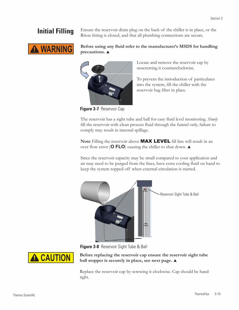
Section 3
ThermoFlex 3-19 Thermo Scientific
Initial Filling Ensure the reservoir drain plug on the back of the chiller is in place, or the Riton fitting is closed, and that all plumbing connections are secure.
Before using any fluid refer to the manufacturer’s MSDS for handling precautions.
The reservoir has a sight tube and ball for easy fluid level monitoring. Slowly fill the reservoir with clean process fluid through the funnel only, failure to comply may result in internal spillage.
Note Filling the reservoir above MAX LEVEL fill line will result in an over flow error (O FLO) causing the chiller to shut down.
Since the reservoir capacity may be small compared to your application and air may need to be purged from the lines, have extra cooling fluid on hand to keep the system topped off when external circulation is started.
Figure 3-7 Reservoir Cap
Before replacing the reservoir cap ensure the reservoir sight tube ball stopper is securely in place, see next page.
Replace the reservoir cap by screwing it clockwise. Cap should be hand tight.
Reservoir Sight Tube & BallMAX
LEVEL
MIN LEVEL
Figure 3-8 Reservoir Sight Tube & Ball
WARNING
Locate and remove the reservoir cap by unscrewing it counterclockwise.
To prevent the introduction of particulates into the system, fill the chiller with the reservoir bag filter in place.
CAUTION
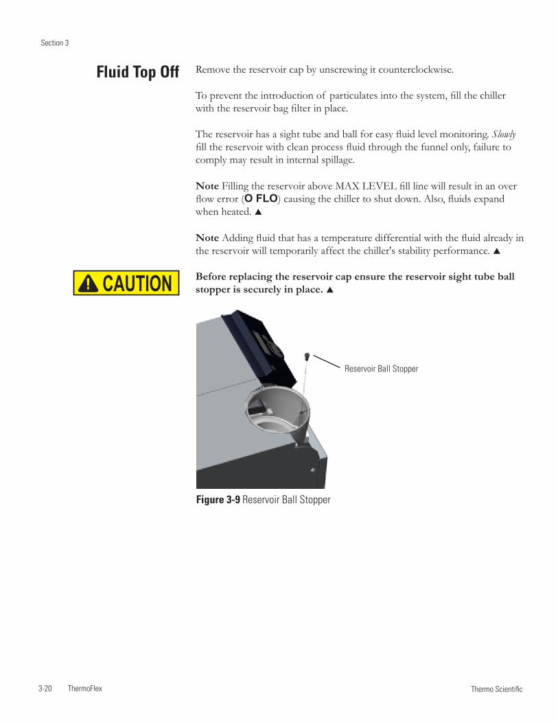
Section 3
3-20 ThermoFlex Thermo Scientific
Fluid Top Off Remove the reservoir cap by unscrewing it counterclockwise.
To prevent the introduction of particulates into the system, fill the chiller with the reservoir bag filter in place.
The reservoir has a sight tube and ball for easy fluid level monitoring. Slowly fill the reservoir with clean process fluid through the funnel only, failure to comply may result in internal spillage.
Note Filling the reservoir above MAX LEVEL fill line will result in an over flow error (O FLO) causing the chiller to shut down. Also, fluids expand when heated.
Note Adding fluid that has a temperature differential with the fluid already in the reservoir will temporarily affect the chiller's stability performance.
Before replacing the reservoir cap ensure the reservoir sight tube ball stopper is securely in place.
Figure 3-9 Reservoir Ball Stopper
Reservoir Ball Stopper
CAUTION
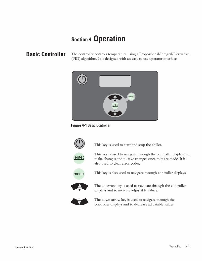
ThermoFlex 4-1 Thermo Scientific
Basic Controller
Section 4 Operation
The controller controls temperature using a Proportional-Integral-Derivative (PID) algorithm. It is designed with an easy to use operator interface.
This key is used to start and stop the chiller.
This key is used to navigate through the controller displays, to make changes and to save changes once they are made. It is also used to clear error codes.
This key is also used to navigate through controller displays.
The up arrow key is used to navigate through the controller displays and to increase adjustable values.
The down arrow key is used to navigate through the controller displays and to decrease adjustable values.
Figure 4-1 Basic Controller
mode
enter
+
-enter
mode
+
-
Section 4
4-2 ThermoFlex Thermo Scientific
Start Up
Setup Note For first time use, please refer to the quick start instructions included with your chiller or the copy in this manual. The manual's version follows the Table of Contents.
Before starting the chiller, double check all electrical and plumbing connections. Have extra recirculating fluid on hand. If the chiller will not start refer to Section 7 Troubleshooting.
If the chiller is equipped with a deionization filter cartridge refer to Section 5 for installation.
• Place the optional GFCI breaker located on the rear to the up position.
• For ThermoFlex900 through 10000s, place the circuit protector located on the rear to the on ( I ) position. The display will indicate a series of upward scrolling bars ( ).
• For ThermoFlex15000 and 24000s, the display will indicate a series of upward scrolling bars ( ) as soon as power is supplied.
• The bars will scroll upward indicating the controller is initializing. The initialization takes approximately 15 seconds.
• When the bars disappear the controller display will go blank.
• Press the key on the controller. The controller will show the process fluid temperature. The pump and refrigeration system will also start. Note You can press the key anytime after placing the circuit protector to the on position.
If the auto restart is enabled and the chiller shuts down as a result of a power failure, when power is restored the chiller will automatically restart. Auto restart is enabled using the Setup Loop, see Setup Loop in this Section.
Note After initial start up, check your plumbing for leaks.
CAUTION
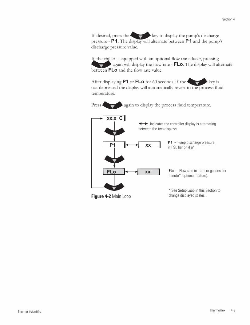
Section 4
ThermoFlex 4-3 Thermo Scientific
If desired, press the key to display the pump's discharge pressure - P 1. The display will alternate between P 1 and the pump's discharge pressure value.
If the chiller is equipped with an optional flow transducer, pressing again will display the flow rate - FLo. The display will alternate
between FLo and the flow rate value.
After displaying P1 or FLo for 60 seconds, if the key is not depressed the display will automatically revert to the process fluid temperature.
Press again to display the process fluid temperature.
P 1 - Pump discharge pressure in PSI, bar or kPa*.
FLo - Flow rate in liters or gallons per minute* (optional feature).
* See Setup Loop in this Section to change displayed scales.
indicates the controller display is alternating between the two displays.
Figure 4-2 Main Loop
FLo
xx.x C
xx
xx
P1
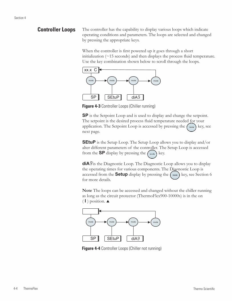
Section 4
4-4 ThermoFlex Thermo Scientific
mode mode modemode
Controller Loops The controller has the capability to display various loops which indicate operating conditions and parameters. The loops are selected and changed by pressing the appropriate keys.
When the controller is first powered up it goes through a short initialization (~15 seconds) and then displays the process fluid temperature. Use the key combination shown below to scroll through the loops.
SP is the Setpoint Loop and is used to display and change the setpoint. The setpoint is the desired process fluid temperature needed for your application. The Setpoint Loop is accessed by pressing the key, see next page.
SEtuP is the Setup Loop. The Setup Loop allows you to display and/or alter different parameters of the controller. The Setup Loop is accessed from the SP display by pressing the key.
diA is the Diagnostic Loop. The Diagnostic Loop allows you to display the operating times for various components. The Diagnostic Loop is accessed from the Setup display by pressing the key, see Section 6 for more details.
Note The loops can be accessed and changed without the chiller running as long as the circuit protector (ThermoFlex900-10000s) is in the on ( I ) position.
Figure 4-3 Controller Loops (Chiller running)
SP SEtuP diA
xx.x C
Figure 4-4 Controller Loops (Chiller not running)
mode mode modemode
SP SEtuP diA
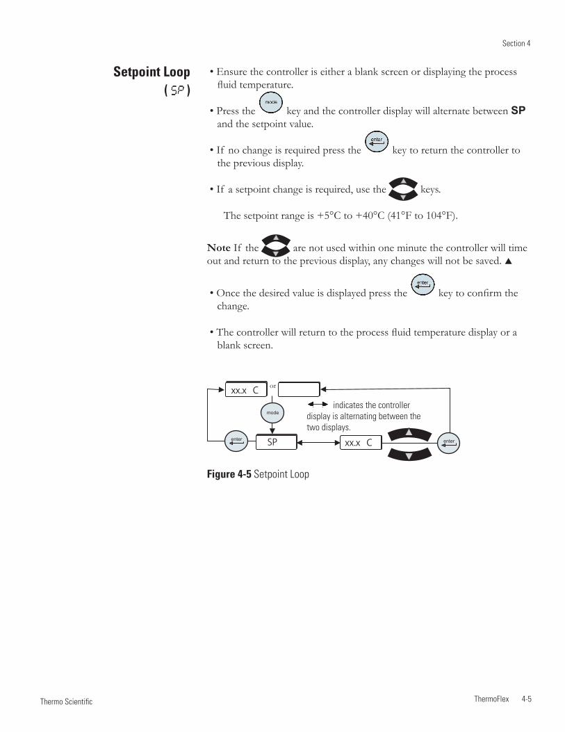
Section 4
ThermoFlex 4-5 Thermo Scientific
SP
xx.x C
xx.x C
mode
enter enter
Setpoint Loop ( )
• Ensure the controller is either a blank screen or displaying the process fluid temperature.
• Press the key and the controller display will alternate between SP and the setpoint value.
• If no change is required press the key to return the controller to the previous display.
• If a setpoint change is required, use the keys.
The setpoint range is +5°C to +40°C (41°F to 104°F).
Note If the are not used within one minute the controller will time out and return to the previous display, any changes will not be saved.
• Once the desired value is displayed press the key to confirm the change.
• The controller will return to the process fluid temperature display or a blank screen.
indicates the controller display is alternating between the two displays.
Figure 4-5 Setpoint Loop
or
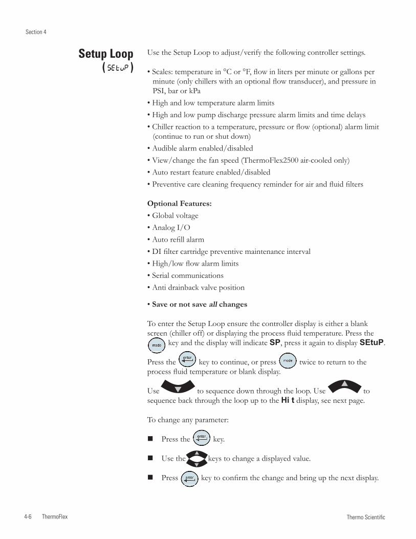
Section 4
4-6 ThermoFlex Thermo Scientific
Setup Loop ( )
Use the Setup Loop to adjust/verify the following controller settings.
• Scales: temperature in °C or °F, flow in liters per minute or gallons per minute (only chillers with an optional flow transducer), and pressure in PSI, bar or kPa
• High and low temperature alarm limits• High and low pump discharge pressure alarm limits and time delays• Chiller reaction to a temperature, pressure or flow (optional) alarm limit
(continue to run or shut down)• Audible alarm enabled/disabled• View/change the fan speed (ThermoFlex2500 air-cooled only)• Auto restart feature enabled/disabled• Preventive care cleaning frequency reminder for air and fluid filters
Optional Features:• Global voltage• Analog I/O• Auto refill alarm• DI filter cartridge preventive maintenance interval• High/low flow alarm limits• Serial communications• Anti drainback valve position
• Save or not save all changes
To enter the Setup Loop ensure the controller display is either a blank screen (chiller off) or displaying the process fluid temperature. Press the
key and the display will indicate SP, press it again to display SEtuP.
Press the key to continue, or press twice to return to the process fluid temperature or blank display.
Use to sequence down through the loop. Use to sequence back through the loop up to the Hi t display, see next page.
To change any parameter:
Press the key.
Use the keys to change a displayed value.
Press key to confirm the change and bring up the next display.
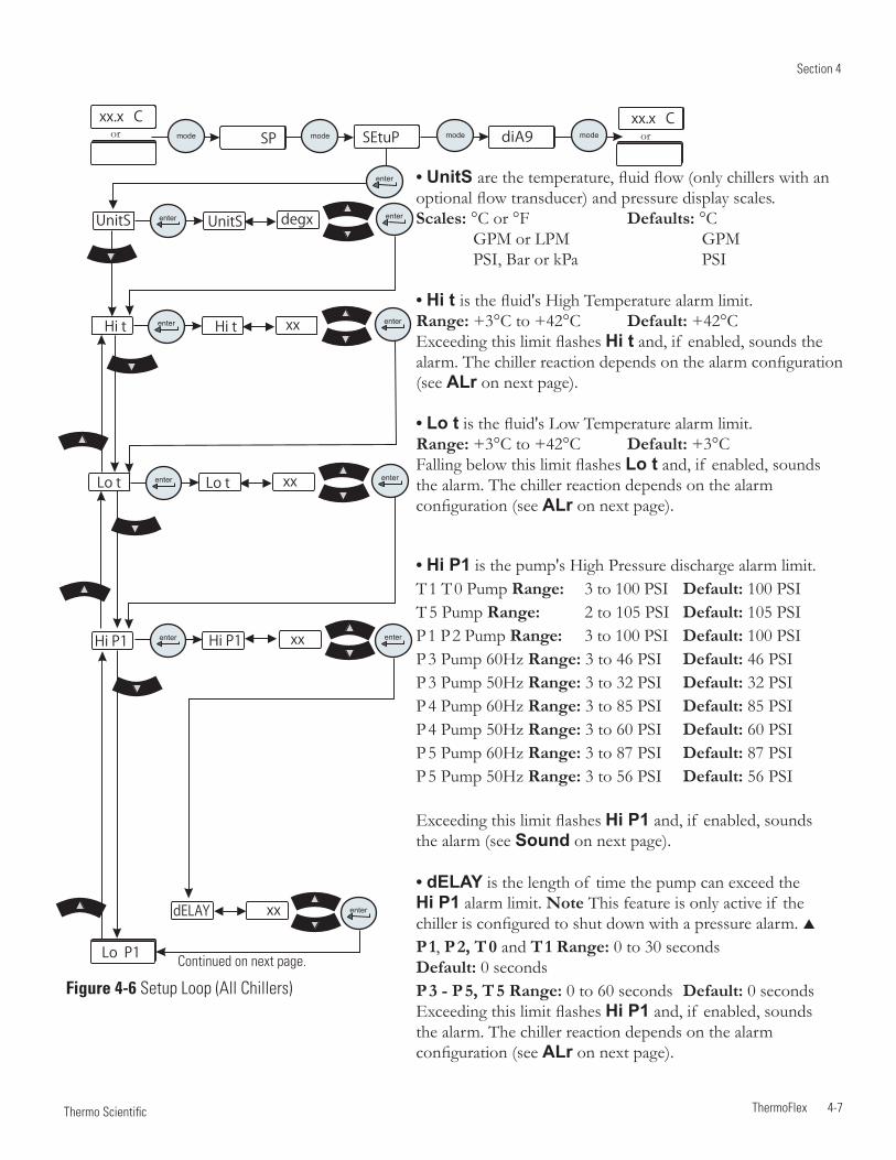
Section 4
ThermoFlex 4-7 Thermo Scientific
diA9SP SEtuP
enter
mode mode mode mode
xx.x C xx.x C
xx
xx
Hi t
UnitS
Lo t Lo t
xx
xx
xx
xx
Hi P1
Lo P1
Hi P1
dELAY enter
enterenter
enter
enter
enter
enter
enter
enter
Hi t
UnitS degx
Lo P1
Figure 4-6 Setup Loop (All Chillers)
or or
Continued on next page.
• UnitS are the temperature, fluid flow (only chillers with an optional flow transducer) and pressure display scales. Scales: °C or °F Defaults: °C GPM or LPM GPM PSI, Bar or kPa PSI • Hi t is the fluid's High Temperature alarm limit. Range: +3°C to +42°C Default: +42°C Exceeding this limit flashes Hi t and, if enabled, sounds the alarm. The chiller reaction depends on the alarm configuration (see ALr on next page).
• Lo t is the fluid's Low Temperature alarm limit. Range: +3°C to +42°C Default: +3°C Falling below this limit flashes Lo t and, if enabled, sounds the alarm. The chiller reaction depends on the alarm configuration (see ALr on next page).
• Hi P1 is the pump's High Pressure discharge alarm limit. T 1 T 0 Pump Range: 3 to 100 PSI Default: 100 PSI T 5 Pump Range: 2 to 105 PSI Default: 105 PSI P 1 P 2 Pump Range: 3 to 100 PSI Default: 100 PSI P 3 Pump 60Hz Range: 3 to 46 PSI Default: 46 PSI P 3 Pump 50Hz Range: 3 to 32 PSI Default: 32 PSI P 4 Pump 60Hz Range: 3 to 85 PSI Default: 85 PSI P 4 Pump 50Hz Range: 3 to 60 PSI Default: 60 PSI P 5 Pump 60Hz Range: 3 to 87 PSI Default: 87 PSI P 5 Pump 50Hz Range: 3 to 56 PSI Default: 56 PSI Exceeding this limit flashes Hi P1 and, if enabled, sounds the alarm (see Sound on next page).
• dELAY is the length of time the pump can exceed the Hi P1 alarm limit. Note This feature is only active if the chiller is configured to shut down with a pressure alarm. P 1, P 2, T 0 and T 1 Range: 0 to 30 seconds Default: 0 seconds P 3 - P 5, T 5 Range: 0 to 60 seconds Default: 0 seconds Exceeding this limit flashes Hi P1 and, if enabled, sounds the alarm. The chiller reaction depends on the alarm configuration (see ALr on next page).
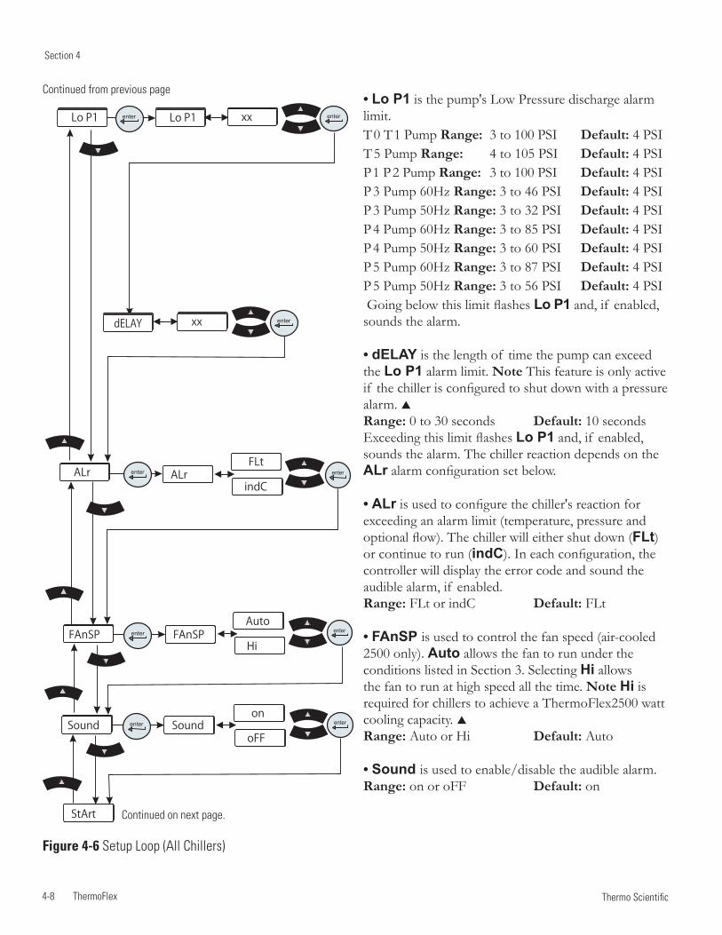
Section 4
4-8 ThermoFlex Thermo Scientific
Figure 4-6 Setup Loop (All Chillers)
• Lo P1 is the pump's Low Pressure discharge alarm limit. T 0 T 1 Pump Range: 3 to 100 PSI Default: 4 PSI T 5 Pump Range: 4 to 105 PSI Default: 4 PSI P 1 P 2 Pump Range: 3 to 100 PSI Default: 4 PSI P 3 Pump 60Hz Range: 3 to 46 PSI Default: 4 PSI P 3 Pump 50Hz Range: 3 to 32 PSI Default: 4 PSI P 4 Pump 60Hz Range: 3 to 85 PSI Default: 4 PSI P 4 Pump 50Hz Range: 3 to 60 PSI Default: 4 PSI P 5 Pump 60Hz Range: 3 to 87 PSI Default: 4 PSI P 5 Pump 50Hz Range: 3 to 56 PSI Default: 4 PSI Going below this limit flashes Lo P1 and, if enabled, sounds the alarm.
• dELAY is the length of time the pump can exceed the Lo P1 alarm limit. Note This feature is only active if the chiller is configured to shut down with a pressure alarm. Range: 0 to 30 seconds Default: 10 seconds Exceeding this limit flashes Lo P1 and, if enabled, sounds the alarm. The chiller reaction depends on the ALr alarm configuration set below.
• ALr is used to configure the chiller's reaction for exceeding an alarm limit (temperature, pressure and optional flow). The chiller will either shut down (FLt) or continue to run (indC). In each configuration, the controller will display the error code and sound the audible alarm, if enabled. Range: FLt or indC Default: FLt
• FAnSP is used to control the fan speed (air-cooled 2500 only). Auto allows the fan to run under the conditions listed in Section 3. Selecting Hi allows the fan to run at high speed all the time. Note Hi is required for chillers to achieve a ThermoFlex2500 watt cooling capacity. Range: Auto or Hi Default: Auto
• Sound is used to enable/disable the audible alarm. Range: on or oFF Default: on
Continued on next page.
Continued from previous page
enter
enterenter
Sound
FAnSP
ALr
Lo P1 Lo P1 xx
xx
on
Auto
oFF
Hi
Sound
FAnSP
enter
enter
StArt
ALrenterFLt
indCenter
enter
enter
dELAY
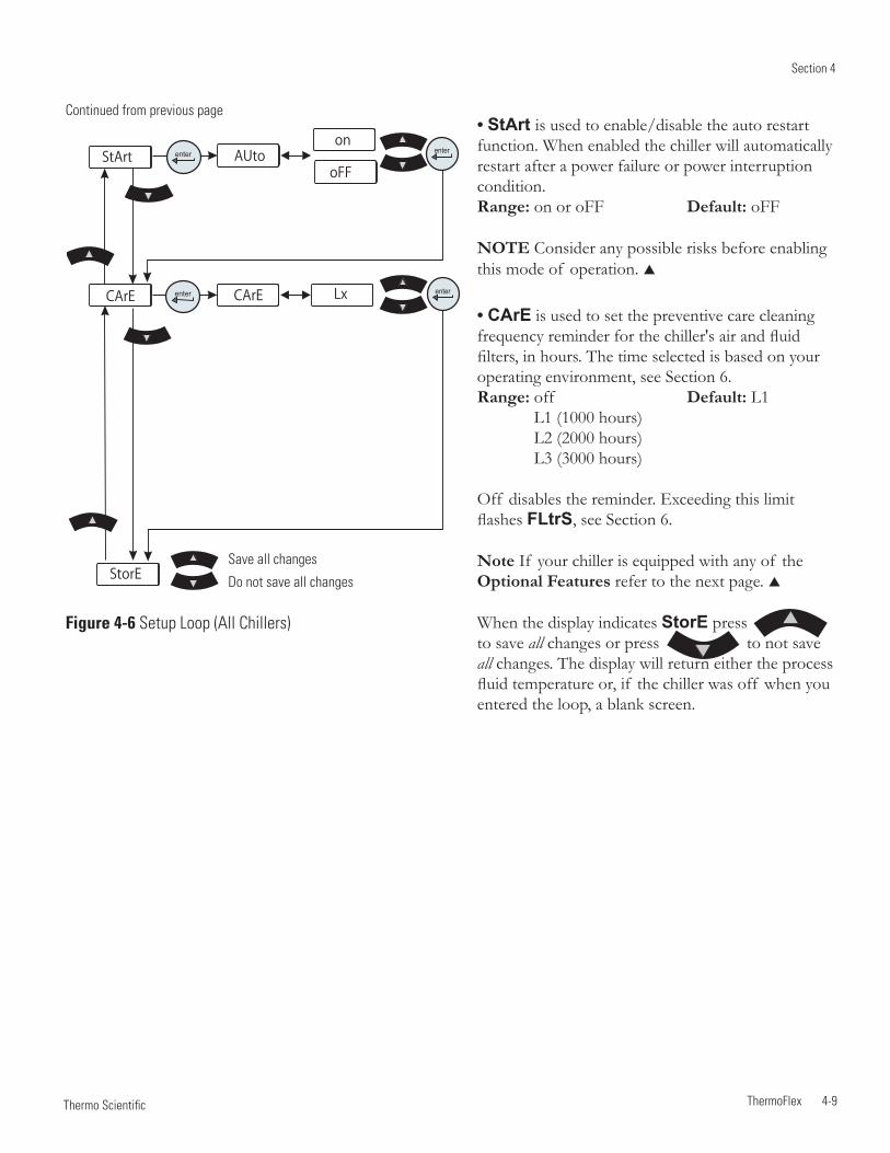
Section 4
ThermoFlex 4-9 Thermo Scientific
Figure 4-6 Setup Loop (All Chillers)
• StArt is used to enable/disable the auto restart function. When enabled the chiller will automatically restart after a power failure or power interruption condition. Range: on or oFF Default: oFF
NOTE Consider any possible risks before enabling this mode of operation.
• CArE is used to set the preventive care cleaning frequency reminder for the chiller's air and fluid filters, in hours. The time selected is based on your operating environment, see Section 6. Range: off Default: L1 L1 (1000 hours) L2 (2000 hours) L3 (3000 hours) Off disables the reminder. Exceeding this limit flashes FLtrS, see Section 6.
Note If your chiller is equipped with any of the Optional Features refer to the next page.
When the display indicates StorE press to save all changes or press to not save all changes. The display will return either the process fluid temperature or, if the chiller was off when you entered the loop, a blank screen.
Continued from previous page
xx
on
oFF
LxCArE
AUto
StorE
StArt
CArE enter
enter
enter
enter
Save all changes
Do not save all changes
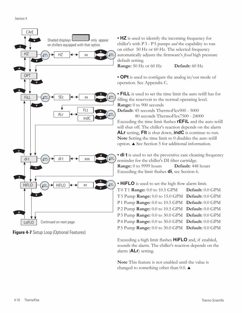
Section 4
4-10 ThermoFlex Thermo Scientific
Figure 4-7 Setup Loop (Optional Features)
Continued on next page.
xx
xxx
xx
xx
FLt
indC
xx
di t
SEc
HZ
ALr
di t
FiLL
LoFLO
HiFLO HiFLO enter
enter
enter
enter
enter
enter
enter
enter
enter
OPT
HZ
CArE• HZ is used to identify the incoming frequency for chiller's with P 3 - P 5 pumps and the capability to run on either 50 Hz or 60 Hz. The selected frequency automatically adjusts the firmware's fixed high pressure default setting. Range: 50 Hz or 60 Hz Default: 60 Hz
• OPt is used to configure the analog in/out mode of operation. See Appendix C.
• FiLL is used to set the time limit the auto refill has for filling the reservoir to the normal operating level. Range: 0 to 900 seconds Default: 45 seconds ThermoFlex900 - 5000 80 seconds ThermoFlex7500 - 24000 Exceeding the time limit flashes rEFiL and the auto refill will shut off. The chiller's reaction depends on the alarm ALr setting, Flt is shut down, indC is continue to run. Note Setting the time limit to 0 disables the auto refill option. See Section 5 for additional information.
• di t is used to set the preventive care cleaning frequency reminder for the chiller's DI filter cartridge. Range: 0 to 9999 hours Default: 448 hours Exceeding the limit flashes di, see Section 6.
• HiFLO is used to set the high flow alarm limit. T 0 T 1 Range: 0.0 to 10.5 GPM Default: 0.0 GPM T 5 Pump Range: 0.0 to 15.0 GPM Default: 0.0 GPM P 1 Pump Range: 0.0 to 10.5 GPM Default: 0.0 GPM P 2 Pump Range: 0.0 to 10.5 GPM Default: 0.0 GPM P 3 Pump Range: 0.0 to 30.0 GPM Default: 0.0 GPM P 4 Pump Range: 0.0 to 30.0 GPM Default: 0.0 GPM P 5 Pump Range: 0.0 to 30.0 GPM Default: 0.0 GPM
Exceeding a high limit flashes HiFLO and, if enabled, sounds the alarm. The chiller's reaction depends on the alarm (ALr) setting.
Note This feature is not enabled until the value is changed to something other than 0.0.
Shaded displays only appear on chillers equipped with that option.
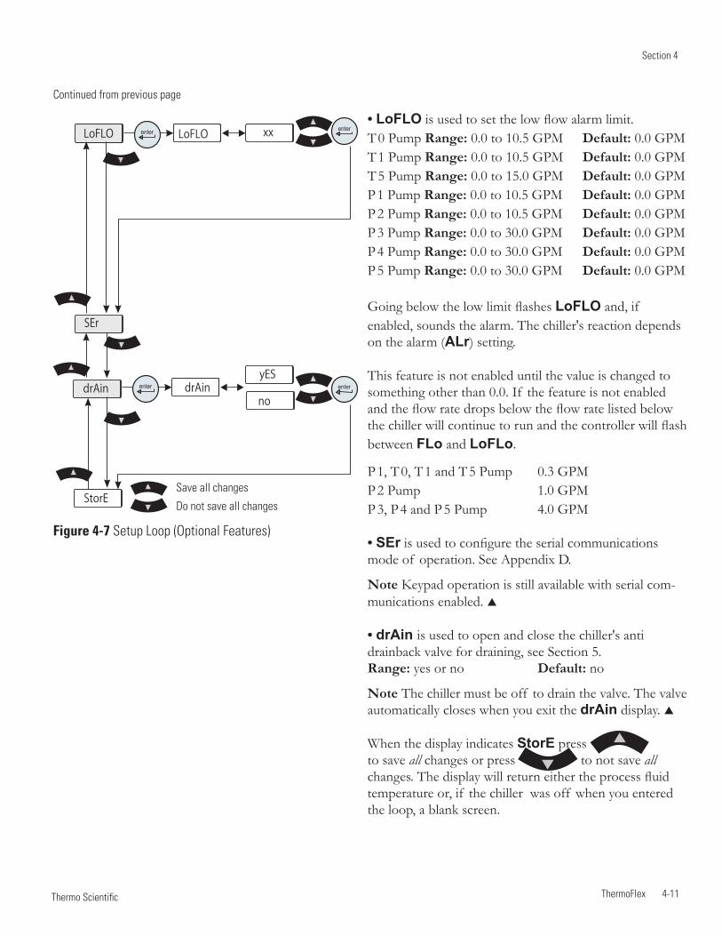
Section 4
ThermoFlex 4-11 Thermo Scientific
yES
nodrAin
StorE
drAin enterenter
SEr
xxxxLoFLO LoFLO enterenter
Figure 4-7 Setup Loop (Optional Features)
• LoFLO is used to set the low flow alarm limit. T 0 Pump Range: 0.0 to 10.5 GPM Default: 0.0 GPM T 1 Pump Range: 0.0 to 10.5 GPM Default: 0.0 GPM T 5 Pump Range: 0.0 to 15.0 GPM Default: 0.0 GPM P 1 Pump Range: 0.0 to 10.5 GPM Default: 0.0 GPM P 2 Pump Range: 0.0 to 10.5 GPM Default: 0.0 GPM P 3 Pump Range: 0.0 to 30.0 GPM Default: 0.0 GPM P 4 Pump Range: 0.0 to 30.0 GPM Default: 0.0 GPM P 5 Pump Range: 0.0 to 30.0 GPM Default: 0.0 GPM
Going below the low limit flashes LoFLO and, if enabled, sounds the alarm. The chiller's reaction depends on the alarm (ALr) setting.
This feature is not enabled until the value is changed to something other than 0.0. If the feature is not enabled and the flow rate drops below the flow rate listed below the chiller will continue to run and the controller will flash between FLo and LoFLo.
P 1, T 0, T 1 and T 5 Pump 0.3 GPM P 2 Pump 1.0 GPM P 3, P 4 and P 5 Pump 4.0 GPM
• SEr is used to configure the serial communications mode of operation. See Appendix D.
Note Keypad operation is still available with serial com-munications enabled.
• drAin is used to open and close the chiller's anti drainback valve for draining, see Section 5. Range: yes or no Default: no
Note The chiller must be off to drain the valve. The valve automatically closes when you exit the drAin display.
When the display indicates StorE press to save all changes or press to not save all changes. The display will return either the process fluid temperature or, if the chiller was off when you entered the loop, a blank screen.
Continued from previous page
Save all changes
Do not save all changes
Section 4
4-12 ThermoFlex Thermo Scientific
Shut Down Press the key on the controller.
Note To protect the chiller's compressor, the chiller will enter a 5 to 20 second shut down cycle (colder process fluids take longer) before the refrigeration system and pump shut down. During this time the display will indicate OFF . The bars will scroll downward indicating the controller is in the shut down cycle.
Using any other means to shut the chiller down can reduce the life of the compressor.
For ThermoFlex900 - 10000 chillers, when the display goes blank it is safe to place the circuit protector located on the rear to the off ( 0 ) position.
Always turn the chiller off and disconnect it from its supply voltage before moving.
For ThermoFlex900 - 10000s, the circuit protector located on the rear is not intended to act as a disconnecting means.
CAUTION
CAUTION
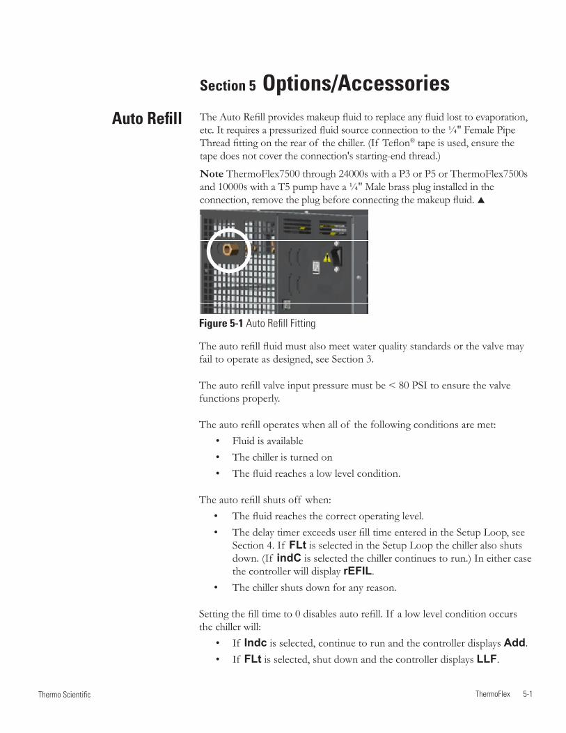
ThermoFlex 5-1 Thermo Scientific
Auto Refill
The auto refill fluid must also meet water quality standards or the valve may fail to operate as designed, see Section 3.
The auto refill valve input pressure must be < 80 PSI to ensure the valve functions properly.
The auto refill operates when all of the following conditions are met: • Fluid is available • The chiller is turned on • The fluid reaches a low level condition.
The auto refill shuts off when:• The fluid reaches the correct operating level.• The delay timer exceeds user fill time entered in the Setup Loop, see
Section 4. If FLt is selected in the Setup Loop the chiller also shuts down. (If indC is selected the chiller continues to run.) In either case the controller will display rEFIL.
• The chiller shuts down for any reason.
Setting the fill time to 0 disables auto refill. If a low level condition occurs the chiller will: • If Indc is selected, continue to run and the controller displays Add. • If FLt is selected, shut down and the controller displays LLF.
Figure 5-1 Auto Refill Fitting
Section 5 Options/AccessoriesThe Auto Refill provides makeup fluid to replace any fluid lost to evaporation, etc. It requires a pressurized fluid source connection to the ¼" Female Pipe Thread fitting on the rear of the chiller. (If Teflon® tape is used, ensure the tape does not cover the connection's starting-end thread.)
Note ThermoFlex7500 through 24000s with a P3 or P5 or ThermoFlex7500s and 10000s with a T5 pump have a ¼" Male brass plug installed in the connection, remove the plug before connecting the makeup fluid.
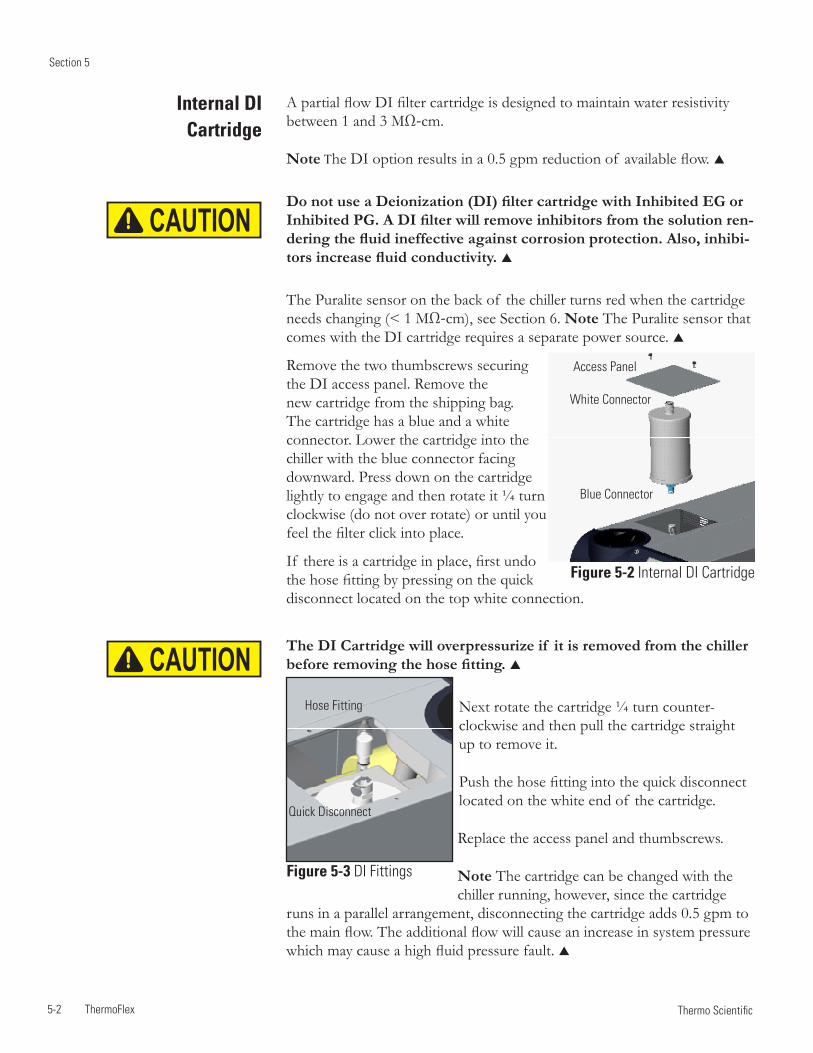
Section 5
5-2 ThermoFlex Thermo Scientific
A partial flow DI filter cartridge is designed to maintain water resistivity between 1 and 3 MΩ-cm.
Note The DI option results in a 0.5 gpm reduction of available flow.
Do not use a Deionization (DI) filter cartridge with Inhibited EG or Inhibited PG. A DI filter will remove inhibitors from the solution ren-dering the fluid ineffective against corrosion protection. Also, inhibi-tors increase fluid conductivity.
The Puralite sensor on the back of the chiller turns red when the cartridge needs changing (< 1 MΩ-cm), see Section 6. Note The Puralite sensor that comes with the DI cartridge requires a separate power source.
Remove the two thumbscrews securing the DI access panel. Remove the new cartridge from the shipping bag. The cartridge has a blue and a white connector. Lower the cartridge into the chiller with the blue connector facing downward. Press down on the cartridge lightly to engage and then rotate it ¼ turn clockwise (do not over rotate) or until you feel the filter click into place.
If there is a cartridge in place, first undo the hose fitting by pressing on the quick disconnect located on the top white connection.
The DI Cartridge will overpressurize if it is removed from the chiller before removing the hose fitting.
Next rotate the cartridge ¼ turn counter-clockwise and then pull the cartridge straight up to remove it.
Push the hose fitting into the quick disconnect located on the white end of the cartridge.
Replace the access panel and thumbscrews.
Note The cartridge can be changed with the chiller running, however, since the cartridge
runs in a parallel arrangement, disconnecting the cartridge adds 0.5 gpm to the main flow. The additional flow will cause an increase in system pressure which may cause a high fluid pressure fault.
Internal DI Cartridge
Quick Disconnect
Hose Fitting
Figure 5-3 DI Fittings
Figure 5-2 Internal DI Cartridge
Blue Connector
White Connector
Access Panel
CAUTION
CAUTION
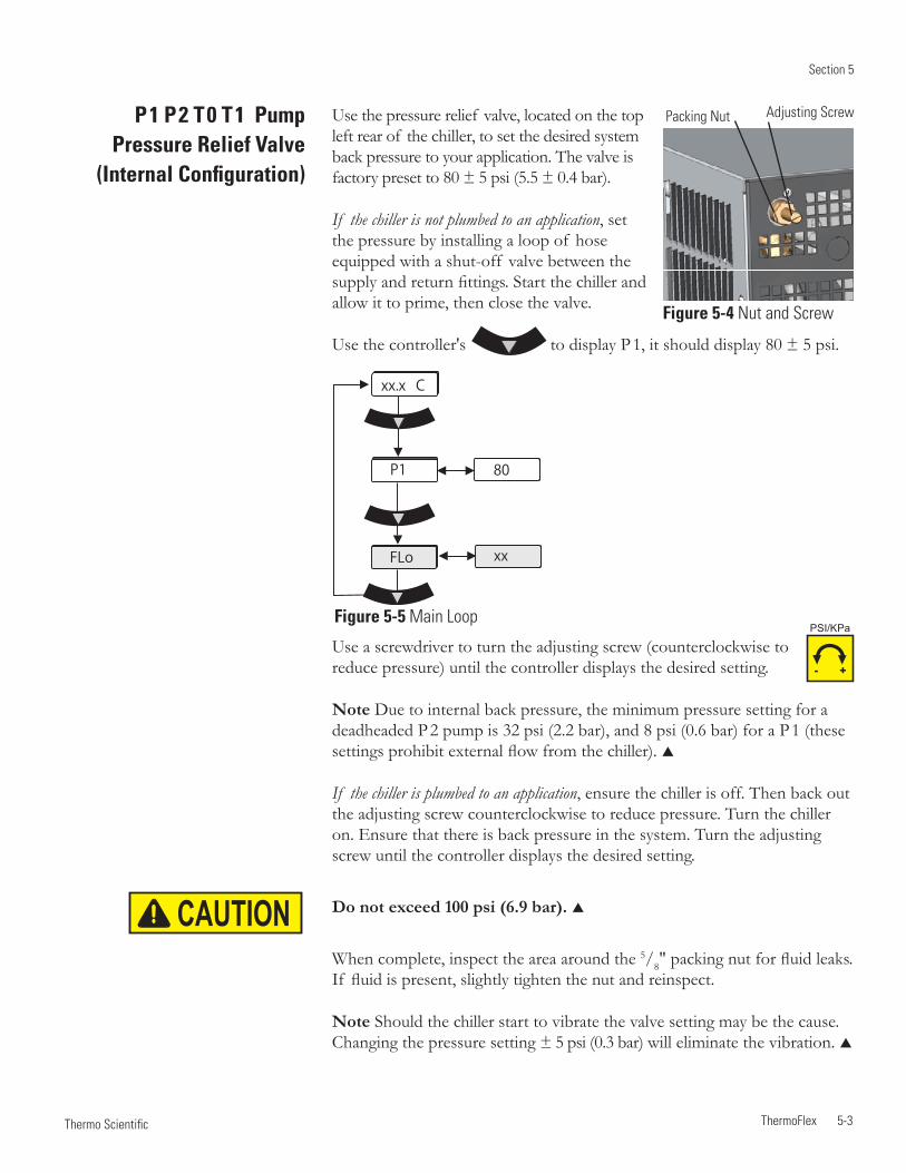
Section 5
ThermoFlex 5-3 Thermo Scientific
P 1 P 2 T 0 T 1 Pump Pressure Relief Valve
(Internal Configuration)
Figure 5-5 Main Loop
Use the pressure relief valve, located on the top left rear of the chiller, to set the desired system back pressure to your application. The valve is factory preset to 80 ± 5 psi (5.5 ± 0.4 bar).
If the chiller is not plumbed to an application, set the pressure by installing a loop of hose equipped with a shut-off valve between the supply and return fittings. Start the chiller and allow it to prime, then close the valve.
Use the controller's to display P 1, it should display 80 ± 5 psi.
Adjusting ScrewPacking Nut
Use a screwdriver to turn the adjusting screw (counterclockwise to reduce pressure) until the controller displays the desired setting.
Note Due to internal back pressure, the minimum pressure setting for a deadheaded P 2 pump is 32 psi (2.2 bar), and 8 psi (0.6 bar) for a P 1 (these settings prohibit external flow from the chiller).
If the chiller is plumbed to an application, ensure the chiller is off. Then back out the adjusting screw counterclockwise to reduce pressure. Turn the chiller on. Ensure that there is back pressure in the system. Turn the adjusting screw until the controller displays the desired setting.
Do not exceed 100 psi (6.9 bar).
When complete, inspect the area around the 5/8" packing nut for fluid leaks. If fluid is present, slightly tighten the nut and reinspect.
Note Should the chiller start to vibrate the valve setting may be the cause. Changing the pressure setting ± 5 psi (0.3 bar) will eliminate the vibration.
Figure 5-4 Nut and Screw
P1
FLo
xx.x C
80
xx
- +
PSI/KPa
CAUTION
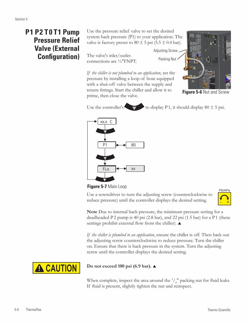
Section 5
5-4 ThermoFlex Thermo Scientific
Figure 5-7 Main Loop
P 1 P 2 T 0 T 1 Pump Pressure Relief Valve (External Configuration)
Use the pressure relief valve to set the desired system back pressure (P1) to your application. The valve is factory preset to 80 ± 5 psi (5.5 ± 0.4 bar).
The valve's inlet/outlet connections are ½"FNPT.
If the chiller is not plumbed to an application, set the pressure by installing a loop of hose equipped with a shut-off valve between the supply and return fittings. Start the chiller and allow it to prime, then close the valve.
Use the controller's to display P 1, it should display 80 ± 5 psi.
Packing Nut
Adjusting Screw
Figure 5-6 Nut and Screw
Use a screwdriver to turn the adjusting screw (counterclockwise to reduce pressure) until the controller displays the desired setting.
Note Due to internal back pressure, the minimum pressure setting for a deadheaded P 2 pump is 40 psi (2.8 bar), and 22 psi (1.5 bar) for a P 1 (these settings prohibit external flow from the chiller).
If the chiller is plumbed to an application, ensure the chiller is off. Then back out the adjusting screw counterclockwise to reduce pressure. Turn the chiller on. Ensure that there is back pressure in the system. Turn the adjusting screw until the controller displays the desired setting.
Do not exceed 100 psi (6.9 bar).
When complete, inspect the area around the 5/8" packing nut for fluid leaks. If fluid is present, slightly tighten the nut and reinspect.
P1
FLo
xx.x C
80
xx
- +
PSI/KPa
CAUTION
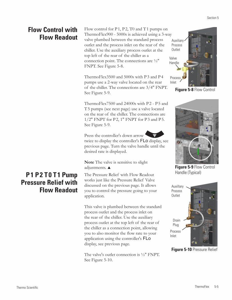
Section 5
ThermoFlex 5-5 Thermo Scientific
Flow Control with Flow Readout
P 1 P 2 T 0 T 1 Pump Pressure Relief with
Flow Readout
Figure 5-8 Flow Control
Figure 5-9 Flow Control Handle (Typical)
Figure 5-10 Pressure Relief
Auxillary Process Outlet
DrainPlug
Valve Handle
Flow control for P 1, P 2, T0 and T 1 pumps on ThermoFlex900 - 5000s is achieved using a 3-way valve plumbed between the standard process outlet and the process inlet on the rear of the chiller. Use the auxiliary process outlet at the top left of the rear of the chiller as a connection point. The connections are ½" FNPT. See Figure 5-8.
ThermoFlex3500 and 5000s with P 3 and P 4 pumps use a 2-way valve located on the rear of the chiller. The connections are 3/4" FNPT. See Figure 5-9.
ThermoFlex7500 and 24000s with P 2 - P 5 and T 5 pumps (see next page) use a valve located on the rear of the chiller. The connections are 1/2" FNPT for P 2, 1" FNPT for P 3 and P 5. See Figure 5-9.
Press the controller's down arrow twice to display the controller's FLo display, see previous page. Turn the valve handle until the desired rate is displayed.
Note The valve is sensitive to slight adjustments.
Auxiliary Process Outlet
Process Inlet
Process Inlet
The Pressure Relief with Flow Readout works just like the Pressure Relief Valve discussed on the previous page. It allows you to control the pressure going to your application.
This valve is plumbed between the standard process outlet and the process inlet on the rear of the chiller. Use the auxiliary process outlet at the top left of the rear of the chiller as a connection point, allowing you to also monitor the flow rate to your application using the controller's FLo display, see previous page.
The valve's outlet connection is ½" FNPT. See Figure 5-10.
Section 5
5-6 ThermoFlex Thermo Scientific
ComplianceSEMI chillers are compliant with: SEMI S2-0703 Product Safety Assessment SEMI S8-0705 Ergonomic Assessment SEMI S14-0704 Fire Risk Assessment SEMI F47-0706
Emergency Off (EMO) A guarded red mushroom shaped push-button switch with twist-to-reset is provided on the chiller's front to turn it off in case of an emergency. The button head is engraved with “EMO” in large white filled letters.
Note The EMO is controlled by a safety circuit and is not influenced by the chiller's firmware/software.
Activation of the EMO button will remove power from the main contactor coil stopping operation of the chiller. The controller will display Er 48.
Resetting the EMO button will not restart the chiller. After all hazards have been removed reset the chiller by pushing the enter key on the controller. In the local mode, the chiller will restart by pressing the START STOP button again. In the serial communications mode, send the appropriate start command. In the analog I/O mode, the chiller starts when the error is cleared.
Chiller Circuit Breaker Interrupt Rating The main power circuit breaker located on the rear of the chiller has an Interrupting Capacity (AIC) of 10,000 amps.
Semiconductor Equipment and
Materials International
(SEMI) Chillers
(ThermoFlex900-10000 only)
Chillers installed below the end-user application may allow system fluid to drain back into the chiller and cause spillage. The anti-drainback valve is designed to prevent any such spillage.
The valve opens just before the pump is turned on and it closes just after the pump shuts off.
This option is required if your chiller is more than 24 feet below your application, or if there is a possibility of drain back due to the opening of the process lines for either application swaps or chiller servicing.
Anti-Drainback
T 5 Pump Flow Control
T 5 Flow Control valve is designed with slots to quickly identify its position. When the slots are in the horizontal position (in line with the discharge line) the application is receiving full flow. With the slots are vertical the valve is in full bypass.
Full Flow Full Bypass
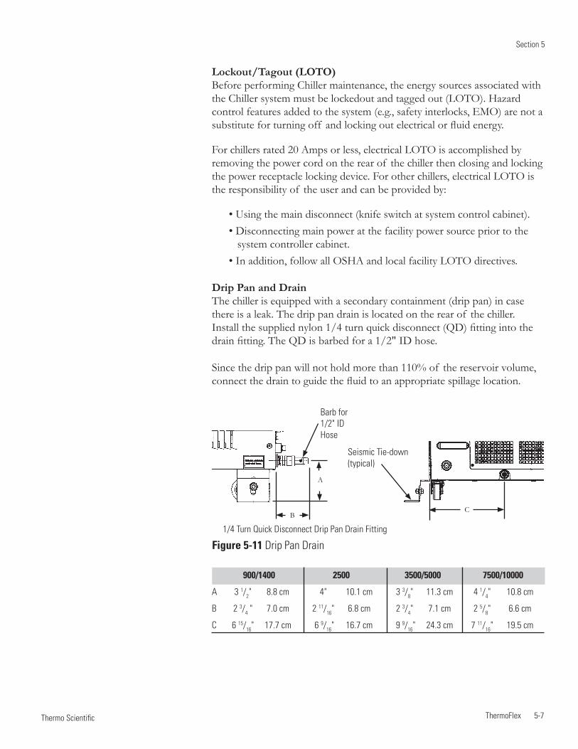
Section 5
ThermoFlex 5-7 Thermo Scientific
A
B
1/4 Turn Quick Disconnect Drip Pan Drain Fitting
C
Barb for 1/2" ID Hose
900/1400 2500 3500/5000 7500/10000
A 3 1/2" 8.8 cm 4" 10.1 cm 3 3/8" 11.3 cm 4 1/4" 10.8 cm
B 2 3/4 " 7.0 cm 2 11/16" 6.8 cm 2 3/4" 7.1 cm 2 5/8" 6.6 cm
C 6 15/16" 17.7 cm 6 9/16" 16.7 cm 9 9/16" 24.3 cm 7 11/16" 19.5 cm
Figure 5-11 Drip Pan Drain
Seismic Tie-down (typical)
Lockout/Tagout (LOTO) Before performing Chiller maintenance, the energy sources associated with the Chiller system must be lockedout and tagged out (LOTO). Hazard control features added to the system (e.g., safety interlocks, EMO) are not a substitute for turning off and locking out electrical or fluid energy.
For chillers rated 20 Amps or less, electrical LOTO is accomplished by removing the power cord on the rear of the chiller then closing and locking the power receptacle locking device. For other chillers, electrical LOTO is the responsibility of the user and can be provided by:
• Using the main disconnect (knife switch at system control cabinet). • Disconnecting main power at the facility power source prior to the system controller cabinet. • In addition, follow all OSHA and local facility LOTO directives.
Drip Pan and Drain The chiller is equipped with a secondary containment (drip pan) in case there is a leak. The drip pan drain is located on the rear of the chiller. Install the supplied nylon 1/4 turn quick disconnect (QD) fitting into the drain fitting. The QD is barbed for a 1/2" ID hose.
Since the drip pan will not hold more than 110% of the reservoir volume, connect the drain to guide the fluid to an appropriate spillage location.
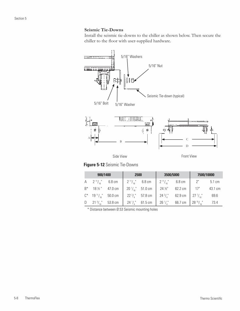
Section 5
5-8 ThermoFlex Thermo Scientific
D
AB
C
Front ViewSide View
900/1400 2500 3500/5000 7500/10000
A 2 11/16" 6.8 cm 2 11/16" 6.8 cm 2 11/16" 6.8 cm 2" 5.1 cm
B* 18 ½ " 47.0 cm 20 1/16" 51.0 cm 24 ½" 62.2 cm 17" 43.1 cm
C* 19 11/16" 50.0 cm 22 3/4" 57.8 cm 24 3/4" 62.9 cm 27 7/16" 69.6
D 21 3/16" 53.8 cm 24 1/4" 61.5 cm 26 1/4" 66.7 cm 28 15/16" 73.4
* Distance between Ø.53 Seismic mounting holes
Figure 5-12 Seismic Tie-Downs
5/16" Bolt
5/16" Nut
5/16" Washer
5/16" Washers
Seismic Tie-Downs Install the seismic tie-downs to the chiller as shown below. Then secure the chiller to the floor with user-supplied hardware.
Seismic Tie-down (typical)
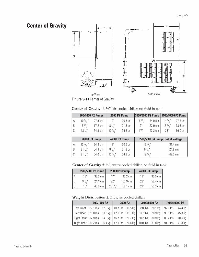
Section 5
ThermoFlex 5-9 Thermo Scientific
Center of Gravity ± ½", air-cooled chiller, no fluid in tank
Center of Gravity ± ½", water-cooled chiller, no fluid in tank
Top View
A
AB
C
Side View
Figure 5-13 Center of Gravity
900/1400 P2 Pump 2500 P2 Pump 3500/5000 P2 Pump 7500/10000 P3 Pump
A 10 3/4 " 27.3 cm 12" 30.5 cm 13 3/8" 34.0 cm 14 7/8" 37.8 cm
B 6 3/4" 17.2 cm 8 3/8" 21.3 cm 9" 22.9 cm 13 1/8" 33.3 cm
C 13 1/2" 34.3 cm 13 1/2" 34.3 cm 17" 43.2 cm 26" 66.0 cm
20000 P3 Pump 24000 P3 Pump 3500/5000 P4 Pump Global Voltage
A 13 3/4 " 34.9 cm 12" 30.5 cm 12 3/8" 31.4 cm
B 21 5/8" 54.9 cm 8 3/8" 21.3 cm 9 3/4" 24.8 cm
C 21 1/4" 54.0 cm 13 1/2" 34.3 cm 19 1/2" 49.5 cm
3500/5000 P2 Pump 20000 P3 Pump 24000 P3 Pump
A 13" 33.0 cm 17" 43.2 cm 12" 30.5 cm
B 9 1/2" 24.1 cm 22" 55.9 cm 23" 58.4 cm
C 16" 40.6 cm 20 1/2" 52.1 cm 21" 53.3 cm
900/1400 P2 2500 P2 3500/5000 P2 7500/10000 P3
Left Front 27.1 lbs 12.3 kg 40.7 lbs 18.5 kg 62.0 lbs 28.1 kg 97.8 lbs 44.4 kg
Left Rear 29.8 lbs 13.5 kg 42.0 lbs 19.1 kg 63.7 lbs 28.9 kg 99.9 lbs 45.3 kg
Right Front 32.9 lbs 14.9 kg 45.7 lbs 20.7 kg 68.2 lbs 30.9 kg 89.2 lbs 40.5 kg
Right Rear 36.2 lbs 16.4 kg 47.1 lbs 21.4 kg 70.0 lbs 31.8 kg 91.1 lbs 41.3 kg
Center of Gravity
Weight Distribution ± 2 lbs, air-cooled chillers
Section 5
5-10 ThermoFlex Thermo Scientific
Installation kit - includes replacement air and fluid filters
Maintenance kit - includes a set of hoses, adaptor fittings and Teflon® tape
Fluids
Fluid treatment kit
Please contact Thermo Fisher Scientific's Sales, Service and Customer Support to assist you with questions that you may have regarding accessories for your ThermoFlex, see inside front cover for contact information.
Other Accessories
ThermoFlex 6-1 Thermo Scientific
Section 6 Preventive Maintenance
Only Thermo Fisher should provide any required replacement parts.
The ThermoFlex chiller has an integrated preventive maintenance timer that will alert you when it is time to perform preventive maintenance. This unique feature will remind you to change your air and fluid filters.
Based on the environment in which your chiller is located, you can choose from four levels of preventive maintenance off, L1, L2, and L3:
• off – Disables the alert • L1 – 1,000 hours - default setting · Heavy manufacturing environment · Airborne particulate created during manufacturing process • L2 – 2,000 hours · Typical production environment • L3 – 3,000 hours · Clean environment – filtered air · Typically laboratory or research environment
Change/set the level using the Setup Loop, see Section 4. When the chiller exceeds the chosen limit, the controller will flash and, if enabled, an audible alarm will sound.
To clear this message press . This will automatically restart the preventive maintenance timer for your filters. Each time the chiller exceeds the chosen time, the controller will remind you that it is time to change your filters.
If you change your filters before the preventive timer trips, you can clear the timer by using the Diagnostic Loop explained in this Section.
Note For air-cooled chillers, both the air and fluid filters in the ThermoFlex can be changed while the chiller is running. For water-cooled chillers, only the fluid filter can be changed while the chiller is running.
Preventive Maintenance Timer
( )
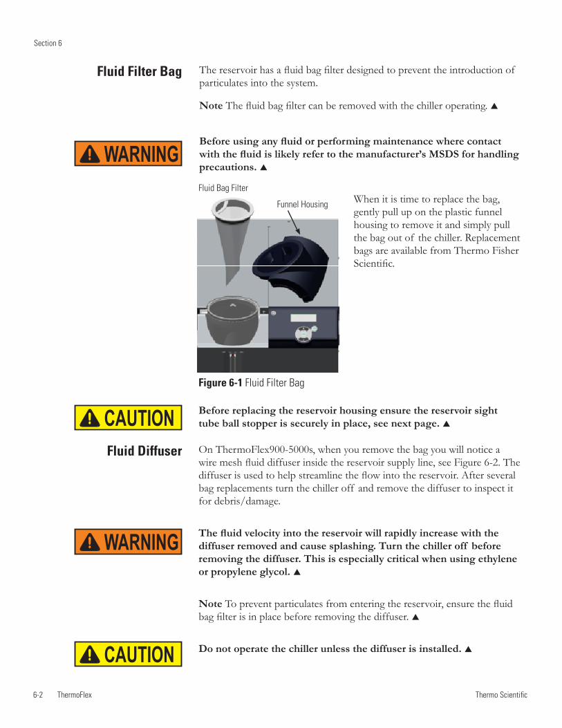
6-2 ThermoFlex
Section 6
Thermo Scientific
The reservoir has a fluid bag filter designed to prevent the introduction of particulates into the system.
Note The fluid bag filter can be removed with the chiller operating.
Before using any fluid or performing maintenance where contact with the fluid is likely refer to the manufacturer’s MSDS for handling precautions.
Fluid Filter Bag
Before replacing the reservoir housing ensure the reservoir sight tube ball stopper is securely in place, see next page.
On ThermoFlex900-5000s, when you remove the bag you will notice a wire mesh fluid diffuser inside the reservoir supply line, see Figure 6-2. The diffuser is used to help streamline the flow into the reservoir. After several bag replacements turn the chiller off and remove the diffuser to inspect it for debris/damage.
The fluid velocity into the reservoir will rapidly increase with the diffuser removed and cause splashing. Turn the chiller off before removing the diffuser. This is especially critical when using ethylene or propylene glycol.
Note To prevent particulates from entering the reservoir, ensure the fluid bag filter is in place before removing the diffuser.
Do not operate the chiller unless the diffuser is installed.
Fluid Bag Filter
Figure 6-1 Fluid Filter Bag
Funnel Housing
Fluid Diffuser
WARNING
WARNING
CAUTION
CAUTION
When it is time to replace the bag, gently pull up on the plastic funnel housing to remove it and simply pull the bag out of the chiller. Replacement bags are available from Thermo Fisher Scientific.
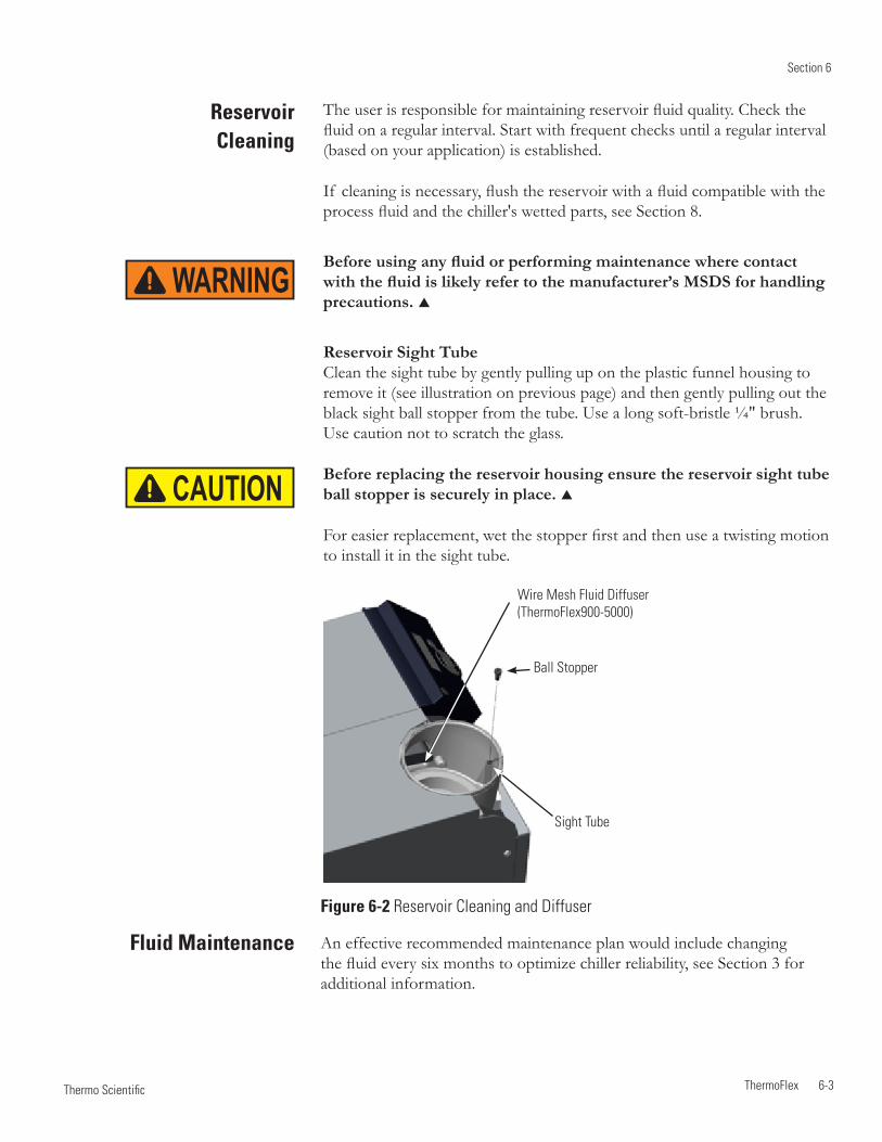
Section 6
ThermoFlex 6-3 Thermo Scientific
Reservoir Cleaning
The user is responsible for maintaining reservoir fluid quality. Check the fluid on a regular interval. Start with frequent checks until a regular interval (based on your application) is established.
If cleaning is necessary, flush the reservoir with a fluid compatible with the process fluid and the chiller's wetted parts, see Section 8.
Before using any fluid or performing maintenance where contact with the fluid is likely refer to the manufacturer’s MSDS for handling precautions.
Reservoir Sight Tube Clean the sight tube by gently pulling up on the plastic funnel housing to remove it (see illustration on previous page) and then gently pulling out the black sight ball stopper from the tube. Use a long soft-bristle ¼" brush. Use caution not to scratch the glass.
Before replacing the reservoir housing ensure the reservoir sight tube ball stopper is securely in place.
For easier replacement, wet the stopper first and then use a twisting motion to install it in the sight tube.
Wire Mesh Fluid Diffuser(ThermoFlex900-5000)
Sight Tube
Ball Stopper
Figure 6-2 Reservoir Cleaning and Diffuser
An effective recommended maintenance plan would include changing the fluid every six months to optimize chiller reliability, see Section 3 for additional information.
Fluid Maintenance
WARNING
CAUTION
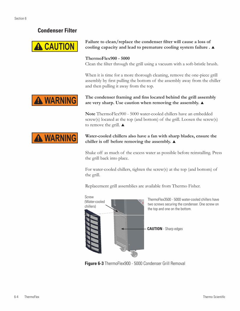
6-4 ThermoFlex
Section 6
Thermo Scientific
Condenser Filter
Failure to clean/replace the condenser filter will cause a loss of cooling capacity and lead to premature cooling system failure .
ThermoFlex900 - 5000 Clean the filter through the grill using a vacuum with a soft-bristle brush.
When it is time for a more thorough cleaning, remove the one-piece grill assembly by first pulling the bottom of the assembly away from the chiller and then pulling it away from the top.
The condenser framing and fins located behind the grill assembly are very sharp. Use caution when removing the assembly.
Note ThermoFlex900 - 5000 water-cooled chillers have an embedded screw(s) located at the top (and bottom) of the grill. Loosen the screw(s) to remove the grill.
Water-cooled chillers also have a fan with sharp blades, ensure the chiller is off before removing the assembly.
Shake off as much of the excess water as possible before reinstalling. Press the grill back into place.
For water-cooled chillers, tighten the screw(s) at the top (and bottom) of the grill.
Replacement grill assemblies are available from Thermo Fisher.
Screw (Water-cooled chillers)
CAUTION - Sharp edges
Figure 6-3 ThermoFlex900 - 5000 Condenser Grill Removal
ThermoFlex3500 - 5000 water-cooled chillers have two screws securing the condenser. One screw on the top and one on the bottom.
WARNING
WARNING
CAUTION
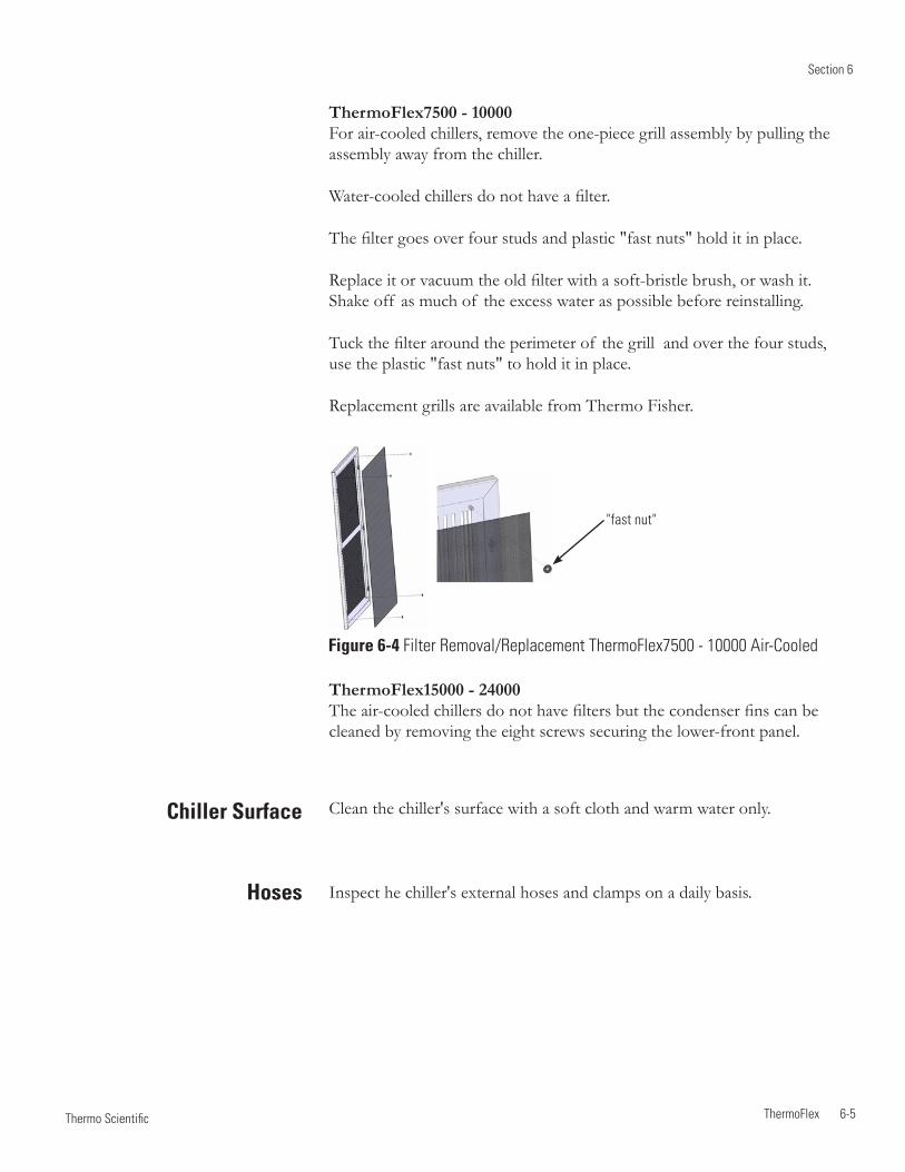
Section 6
ThermoFlex 6-5 Thermo Scientific
Chiller Surface
Hoses
ThermoFlex7500 - 10000 For air-cooled chillers, remove the one-piece grill assembly by pulling the assembly away from the chiller.
Water-cooled chillers do not have a filter.
The filter goes over four studs and plastic "fast nuts" hold it in place.
Replace it or vacuum the old filter with a soft-bristle brush, or wash it. Shake off as much of the excess water as possible before reinstalling.
Tuck the filter around the perimeter of the grill and over the four studs, use the plastic "fast nuts" to hold it in place.
Replacement grills are available from Thermo Fisher.
Figure 6-4 Filter Removal/Replacement ThermoFlex7500 - 10000 Air-Cooled
"fast nut"
Clean the chiller's surface with a soft cloth and warm water only.
Inspect he chiller's external hoses and clamps on a daily basis.
ThermoFlex15000 - 24000 The air-cooled chillers do not have filters but the condenser fins can be cleaned by removing the eight screws securing the lower-front panel.
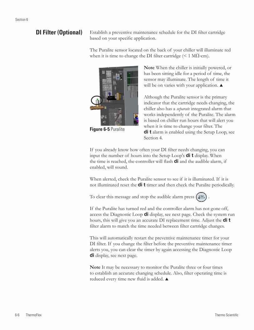
6-6 ThermoFlex
Section 6
Thermo Scientific
DI Filter (Optional) Establish a preventive maintenance schedule for the DI filter cartridge based on your specific application.
The Puralite sensor located on the back of your chiller will illuminate red when it is time to change the DI filter cartridge (< 1 MΩ-cm).
Note When the chiller is initially powered, or has been sitting idle for a period of time, the sensor may illuminate. The length of time it will be on varies with your application.
Although the Puralite sensor is the primary indicator that the cartridge needs changing, the chiller also has a separate integrated alarm that works independently of the Puralite. The alarm is based on chiller run hours that will alert you when it is time to change your filter. The di t alarm is enabled using the Setup Loop, see Section 4.
If you already know how often your DI filter needs changing, you can input the number of hours into the Setup Loop's di t display. When the time is reached, the controller will flash di and the audible alarm, if enabled, will sound.
When alerted, check the Puralite sensor to see if it is illuminated. If it is not illuminated reset the di t timer and then check the Puralite periodically.
To clear this message and stop the audible alarm press .
If the Puralite has turned red and the controller alarm has not gone off, access the Diagnostic Loop di display, see next page. Check the system run hours, this will give you an accurate DI replacement time. Adjust the di t filter alarm to match the time needed between filter cartridge changes.
This will automatically restart the preventive maintenance timer for your DI filter. If you change the filter before the preventive maintenance timer alerts you, you can clear the timer by again accessing the Diagnostic Loop di display, see next page.
Note It may be necessary to monitor the Puralite three or four times to establish an accurate changing schedule. Also, filter operating time is reduced every time new fluid is added.
Figure 6-5 Puralite
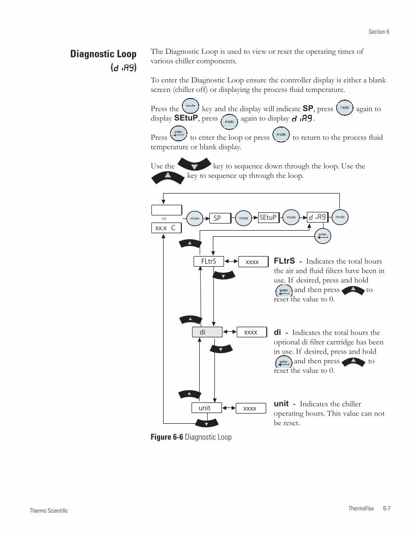
Section 6
ThermoFlex 6-7 Thermo Scientific
The Diagnostic Loop is used to view or reset the operating times of various chiller components.
To enter the Diagnostic Loop ensure the controller display is either a blank screen (chiller off) or displaying the process fluid temperature.
Press the key and the display will indicate SP, press again to display SEtuP, press again to display .
Press to enter the loop or press to return to the process fluid temperature or blank display.
Use the key to sequence down through the loop. Use the key to sequence up through the loop.
Figure 6-6 Diagnostic Loop
Diagnostic Loop ( )
FLtrS xxxx
xxxx
xxxx
di
unit
SP SEtuP
enter
mode mode mode mode
xx.x Cor
FLtrS - Indicates the total hours the air and fluid filters have been in use. If desired, press and hold and then press to reset the value to 0.
di - Indicates the total hours the optional di filter cartridge has been in use. If desired, press and hold and then press to reset the value to 0.
unit - Indicates the chiller operating hours. This value can not be reset.

6-8 ThermoFlex
Section 6
Thermo Scientific
Testing the Alarm Features
Using the Setup Loop, adjust each temperature alarm limit towards the setpoint and ensure the chiller reacts accordingly. Reset each alarm limit to the desired value. See Section 4.
Slowly drain the chiller's reservoir, see Section 8, and ensure the chiller shuts down. For chillers equipped with auto refill switch ensure the auto refill activates.
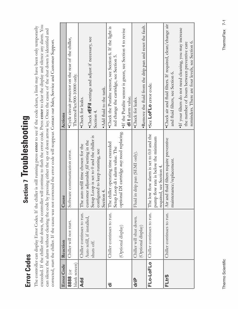
Ther
mo
Sci
entifi
c
The
rmoF
lex
7-
1
Erro
r Cod
esT
he c
ontro
ller c
an d
isplay
Err
or C
odes
. If
the
chill
er is
still
runn
ing
pres
s ent
er to
see
if th
e co
de c
lear
s, a
limit
may
hav
e be
en o
nly
tem
pora
rily
exce
eded
. If
the
chill
er sh
ut d
own,
the
cont
rolle
r will
con
tinue
to fl
ash
the
erro
r cod
e. Pr
ess e
nter
to c
lear
the
disp
lay a
nd si
lenc
e an
y al
arm
. You
ca
n sil
ence
the
alar
m w
ithou
t cle
arin
g th
e co
de b
y pr
essin
g ei
ther
the
up o
r dow
n ar
row
key
. Onc
e th
e ca
use
of th
e sh
ut d
own
is id
entifi
ed a
nd
corr
ecte
d, st
art t
he c
hille
r. If
the
caus
e w
as n
ot c
orre
cted
the
erro
r cod
e w
ill re
appe
ar. C
onta
ct o
ur S
ales
, Ser
vice
and
Cus
tom
er S
uppo
rt.
Sect
ion
7 Tr
oubl
esho
otin
g
Err
or C
ode
Rea
ctio
nC
ause
Act
ions
8888
(or
blan
k sc
reen
)C
hille
r will
not
sta
rt.
Soft
war
e co
mm
unic
atio
n er
ror.
• Cyc
le c
ircui
t pro
tect
or o
n th
e re
ar o
f th
e ch
iller
, T
herm
oFle
x900
-100
00 o
nly.
Add
Chi
ller c
ontin
ues
to ru
n.A
uto
refil
l, if
inst
alle
d,
shut
s of
f.
The
aut
o re
fill t
ime
chos
en fo
r the
cu
stom
er a
djus
tabl
e fil
l set
ting
in th
e Se
tup
Loop
is s
et to
0 a
nd th
e ch
iller
is
confi
gure
d to
kee
p ru
nnin
g, s
ee
Sect
ion
4.
•Che
ck fo
r lea
ks.
•Che
ck rE
Fil s
ettin
gs a
nd a
djus
t if
nece
ssar
y, se
e Se
ctio
n 4.
• Add
flui
d to
the
tank
.di
Chi
ller c
ontin
ues
to ru
n.
(Opt
iona
l disp
lay)
The
chi
ller o
pera
ting
time
exce
eded
Se
tup
Loop
di t
ala
rm v
alue
. The
op
tiona
l DI c
artr
idge
may
nee
d re
plac
ing.
• Che
ck th
e Pu
ralit
e se
nsor
, see
Sec
tion
6. If
the
light
is
red
chan
ge th
e ca
rtrid
ge, s
ee S
ectio
n 5.
• If
the
Pura
lite
sens
or is
gre
en, s
ee S
ectio
n 4
to re
vise
di
t al
arm
val
ue.
driP
Chi
ller w
ill s
hut d
own.
(Opt
iona
l disp
lay)
Flui
d in
drip
pan
(SE
MI o
nly)
.•C
heck
for l
eaks
.
•Rem
ove
the
fluid
from
the
drip
pan
and
rese
t the
faul
t.FL
o-Lo
FLo
Chi
ller c
ontin
ues
to ru
n.T
he lo
w fl
ow a
larm
is s
et to
0.0
and
the
pum
p flo
w ra
te is
bel
ow th
e m
inim
um
requ
ired,
see
Sec
tion
4.
•See
LoF
Lo e
rror
cod
e.
FLtr
SC
hille
r con
tinue
s to
run.
Air
and
fluid
filte
rs re
quire
pre
vent
ive
mai
nten
ance
/rep
lace
men
t.• C
heck
air
and
fluid
filte
rs. I
f re
quire
d, c
lean
/cha
nge
air
and
fluid
filte
rs, s
ee S
ectio
n 6.
• If
your
filte
rs d
o no
t nee
d cl
eani
ng, y
ou m
ay in
crea
se
the
num
ber o
f ho
urs
betw
een
prev
entiv
e ca
re
rem
inde
rs. T
here
are
four
leve
ls, s
ee S
ectio
n 6.
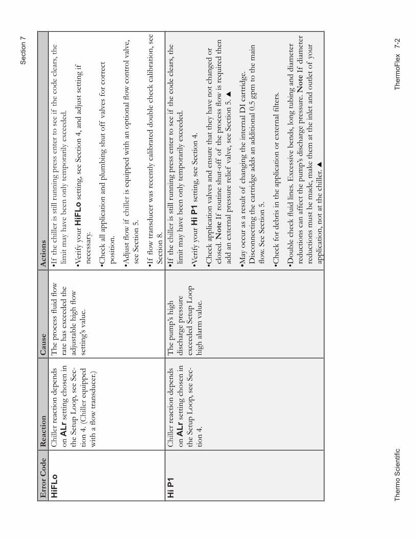
The
rmo
Sci
entifi
c
Ther
moF
lex
7-2
Sec
tion
7
Err
or C
ode
Rea
ctio
nC
ause
Act
ions
HiF
LoC
hille
r rea
ctio
n de
pend
s on
ALr
set
ting
chos
en in
th
e Se
tup
Loop
, see
Sec
-tio
n 4.
(Chi
ller e
quip
ped
with
a fl
ow tr
ansd
ucer
.)
The
pro
cess
flui
d flo
w
rate
has
exc
eede
d th
e ad
just
able
hig
h flo
w
setti
ng’s
valu
e.
• If
the
chill
er is
stil
l run
ning
pre
ss e
nter
to s
ee if
the
code
cle
ars,
the
limit
may
hav
e be
en o
nly
tem
pora
rily
exce
eded
.
• Ver
ify y
our H
iFLo
set
ting,
see
Sec
tion
4, a
nd a
djus
t set
ting
if
nece
ssar
y.
• Che
ck a
ll ap
plic
atio
n an
d pl
umbi
ng s
hut o
ff v
alve
s fo
r cor
rect
po
sitio
n.
• Adj
ust fl
ow if
chi
ller i
s eq
uipp
ed w
ith a
n op
tiona
l flow
con
trol
val
ve,
see
Sect
ion
5.
• If
flow
tran
sduc
er w
as re
cent
ly c
alib
rate
d do
uble
che
ck c
alib
ratio
n, s
ee
Sect
ion
8.H
i P1
Chi
ller r
eact
ion
depe
nds
on A
Lr s
ettin
g ch
osen
in
the
Setu
p Lo
op, s
ee S
ec-
tion
4.
The
pum
p’s
high
di
scha
rge
pres
sure
ex
ceed
ed S
etup
Loo
p hi
gh a
larm
val
ue.
•If
the
chill
er is
stil
l run
ning
pre
ss e
nter
to s
ee if
the
code
cle
ars,
the
limit
may
hav
e be
en o
nly
tem
pora
rily
exce
eded
.
•Ver
ify y
our H
i P1
setti
ng, s
ee S
ectio
n 4.
• Che
ck a
pplic
atio
n va
lves
and
ens
ure
that
they
hav
e no
t cha
nged
or
clos
ed. N
ote
If ro
utin
e sh
ut-o
ff o
f th
e pr
oces
s flo
w is
requ
ired
then
ad
d an
ext
erna
l pre
ssur
e re
lief
valv
e, s
ee S
ectio
n 5.
•May
occ
ur a
s a
resu
lt of
cha
ngin
g th
e in
tern
al D
I car
trid
ge.
Disc
onne
ctin
g th
e ca
rtrid
ge a
dds
an a
dditi
onal
0.5
gpm
to th
e m
ain
flow.
See
Sec
tion
5.
•Che
ck fo
r deb
ris in
the
appl
icat
ion
or e
xter
nal fi
lters
.
• Dou
ble
chec
k flu
id li
nes.
Exc
essiv
e be
nds,
long
tubi
ng a
nd d
iam
eter
re
duct
ions
can
aff
ect t
he p
ump’
s di
scha
rge
pres
sure
. Not
e If
dia
met
er
redu
ctio
ns m
ust b
e m
ade,
mak
e th
em a
t the
inle
t and
out
let o
f yo
ur
appl
icat
ion,
not
at t
he c
hille
r.
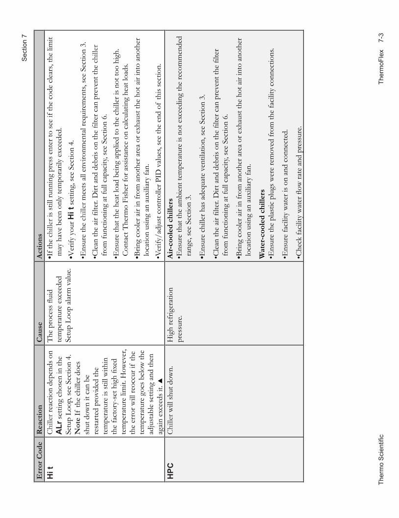
Ther
mo
Sci
entifi
c
The
rmoF
lex
7-
3
Sec
tion
7
Err
or C
ode
Rea
ctio
nC
ause
Act
ions
Hi t
Chi
ller r
eact
ion
depe
nds o
n A
Lr se
tting
cho
sen
in th
e Se
tup
Loop
, see
Sec
tion
4.N
ote
If th
e ch
iller
doe
s sh
ut d
own
it ca
n be
re
star
ted
prov
ided
the
tem
pera
ture
is st
ill w
ithin
th
e fa
ctor
y-se
t hig
h fix
ed
tem
pera
ture
lim
it. H
owev
er,
the
erro
r will
reoc
cur i
f th
e te
mpe
ratu
re g
oes b
elow
the
adju
stab
le se
tting
and
then
ag
ain
exce
eds i
t.
The
pro
cess
flui
d te
mpe
ratu
re e
xcee
ded
Setu
p Lo
op a
larm
val
ue.
•If t
he c
hille
r is s
till r
unni
ng p
ress
ent
er to
see
if th
e co
de c
lear
s, th
e lim
it m
ay h
ave
been
onl
y te
mpo
raril
y ex
ceed
ed.
•Ver
ify y
our H
i t se
tting
, see
Sec
tion
4.•E
nsur
e th
e ch
iller
mee
ts a
ll en
viro
nmen
tal r
equi
rem
ents,
see
Sect
ion
3.• C
lean
the
air fi
lter.
Dirt
and
deb
ris o
n th
e fil
ter c
an p
reve
nt th
e ch
iller
fr
om fu
nctio
ning
at f
ull c
apac
ity, s
ee S
ectio
n 6.
• Ens
ure
that
the
heat
load
bei
ng a
pplie
d to
the
chill
er is
not
too
high
. C
onta
ct T
herm
o Fi
sher
for a
ssist
ance
on
calc
ulat
ing
heat
load
s.•B
ring
cool
er a
ir in
from
ano
ther
are
a or
exh
aust
the
hot a
ir in
to a
noth
er
loca
tion
usin
g an
aux
iliar
y fa
n.•V
erify
/adj
ust c
ontro
ller P
ID v
alue
s, se
e th
e en
d of
this
sect
ion.
HPC
Chi
ller w
ill sh
ut d
own.
Hig
h re
frig
erat
ion
pres
sure
. A
ir-co
oled
chi
llers
• Ens
ure
that
the
ambi
ent t
empe
ratu
re is
not
exc
eedi
ng th
e re
com
men
ded
rang
e, se
e Se
ctio
n 3.
•Ens
ure
chill
er h
as a
dequ
ate
vent
ilatio
n, se
e Se
ctio
n 3.
• Cle
an th
e ai
r filte
r. D
irt a
nd d
ebris
on
the
filte
r can
pre
vent
the
filte
r fr
om fu
nctio
ning
at f
ull c
apac
ity, s
ee S
ectio
n 6.
•Brin
g co
oler
air
in fr
om a
noth
er a
rea
or e
xhau
st th
e ho
t air
into
ano
ther
lo
catio
n us
ing
an a
uxili
ary
fan.
Wat
er-c
oole
d ch
iller
s•E
nsur
e th
e pl
astic
plu
gs w
ere
rem
oved
from
the
faci
lity
conn
ectio
ns.
•Ens
ure
faci
lity
wat
er is
on
and
conn
ecte
d.
•Che
ck fa
cilit
y w
ater
flow
rate
and
pre
ssur
e.
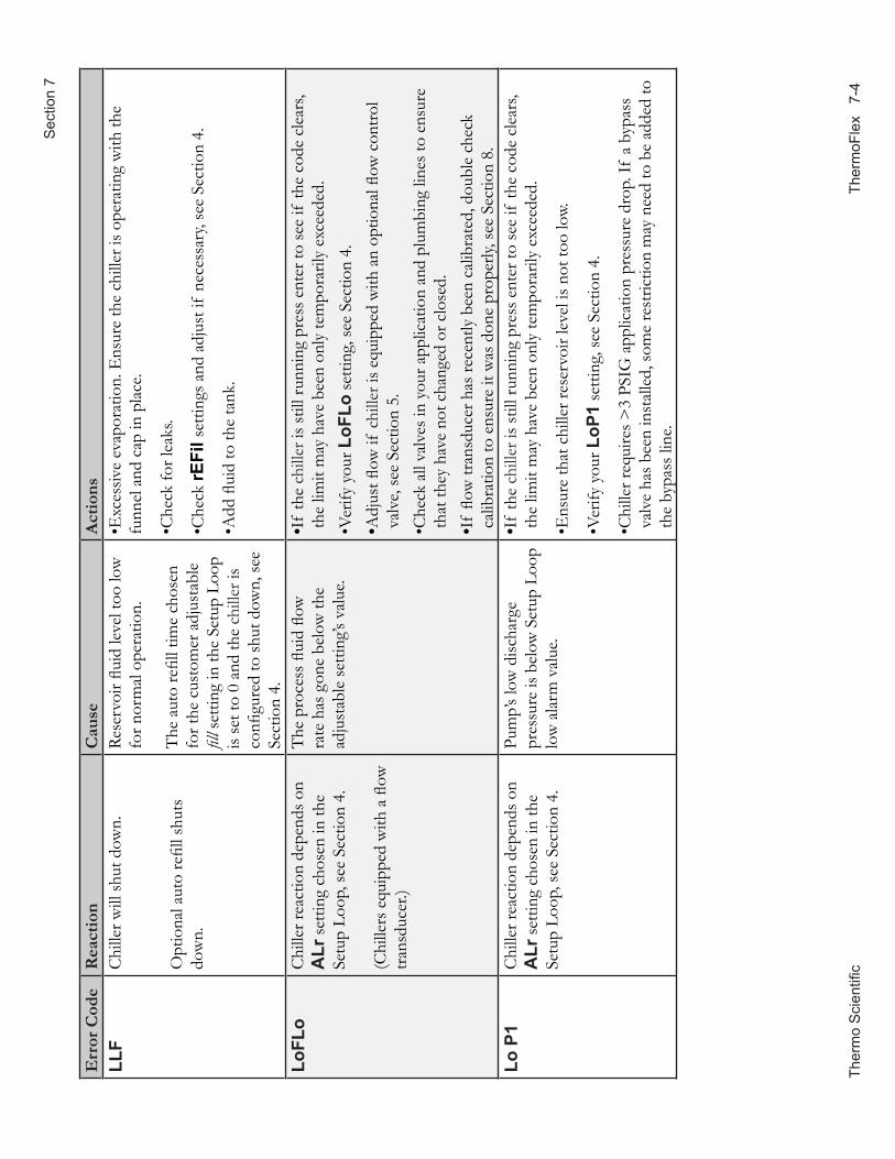
The
rmo
Sci
entifi
c
Ther
moF
lex
7-4
Sec
tion
7
Err
or C
ode
Rea
ctio
nC
ause
Act
ions
LLF
Chi
ller w
ill sh
ut d
own.
Opt
iona
l aut
o re
fill s
huts
do
wn.
Rese
rvoi
r flui
d le
vel t
oo lo
w
for n
orm
al o
pera
tion.
The
aut
o re
fill t
ime
chos
en
for t
he c
usto
mer
adj
usta
ble
fill s
ettin
g in
the
Setu
p Lo
op
is se
t to
0 an
d th
e ch
iller
is
confi
gure
d to
shut
dow
n, se
e Se
ctio
n 4.
•Exc
essiv
e ev
apor
atio
n. E
nsur
e th
e ch
iller
is o
pera
ting
with
the
fu
nnel
and
cap
in p
lace
.
•Che
ck fo
r lea
ks.
•Che
ck rE
Fil s
ettin
gs a
nd a
djus
t if
nece
ssar
y, se
e Se
ctio
n 4.
• Add
flui
d to
the
tank
.
LoFL
oC
hille
r rea
ctio
n de
pend
s on
ALr
setti
ng c
hose
n in
the
Setu
p Lo
op, s
ee S
ectio
n 4.
(Chi
llers
equ
ippe
d w
ith a
flow
tra
nsdu
cer.)
The
pro
cess
flui
d flo
w
rate
has
gon
e be
low
the
adju
stab
le se
tting
’s va
lue.
•If
the
chill
er is
still
runn
ing
pres
s ent
er to
see
if th
e co
de c
lear
s, th
e lim
it m
ay h
ave
been
onl
y te
mpo
raril
y ex
ceed
ed.
•Ver
ify y
our L
oFLo
setti
ng, s
ee S
ectio
n 4.
•Adj
ust fl
ow if
chi
ller i
s equ
ippe
d w
ith a
n op
tiona
l flow
con
trol
valv
e, se
e Se
ctio
n 5.
• Che
ck a
ll va
lves
in y
our a
pplic
atio
n an
d pl
umbi
ng li
nes t
o en
sure
th
at th
ey h
ave
not c
hang
ed o
r clo
sed.
•I
f flo
w tr
ansd
ucer
has
rece
ntly
bee
n ca
libra
ted,
dou
ble
chec
k ca
libra
tion
to e
nsur
e it
was
don
e pr
oper
ly, se
e Se
ctio
n 8.
Lo P
1C
hille
r rea
ctio
n de
pend
s on
ALr
setti
ng c
hose
n in
the
Setu
p Lo
op, s
ee S
ectio
n 4.
Pum
p’s l
ow d
ischa
rge
pres
sure
is b
elow
Set
up L
oop
low
ala
rm v
alue
.
•If
the
chill
er is
still
runn
ing
pres
s ent
er to
see
if th
e co
de c
lear
s, th
e lim
it m
ay h
ave
been
onl
y te
mpo
raril
y ex
ceed
ed.
•Ens
ure
that
chi
ller r
eser
voir
leve
l is n
ot to
o lo
w.
•Ver
ify y
our L
oP1
setti
ng, s
ee S
ectio
n 4.
• Chi
ller r
equi
res >
3 PS
IG a
pplic
atio
n pr
essu
re d
rop.
If a
byp
ass
valv
e ha
s bee
n in
stal
led,
som
e re
stric
tion
may
nee
d to
be
adde
d to
th
e by
pass
line
.
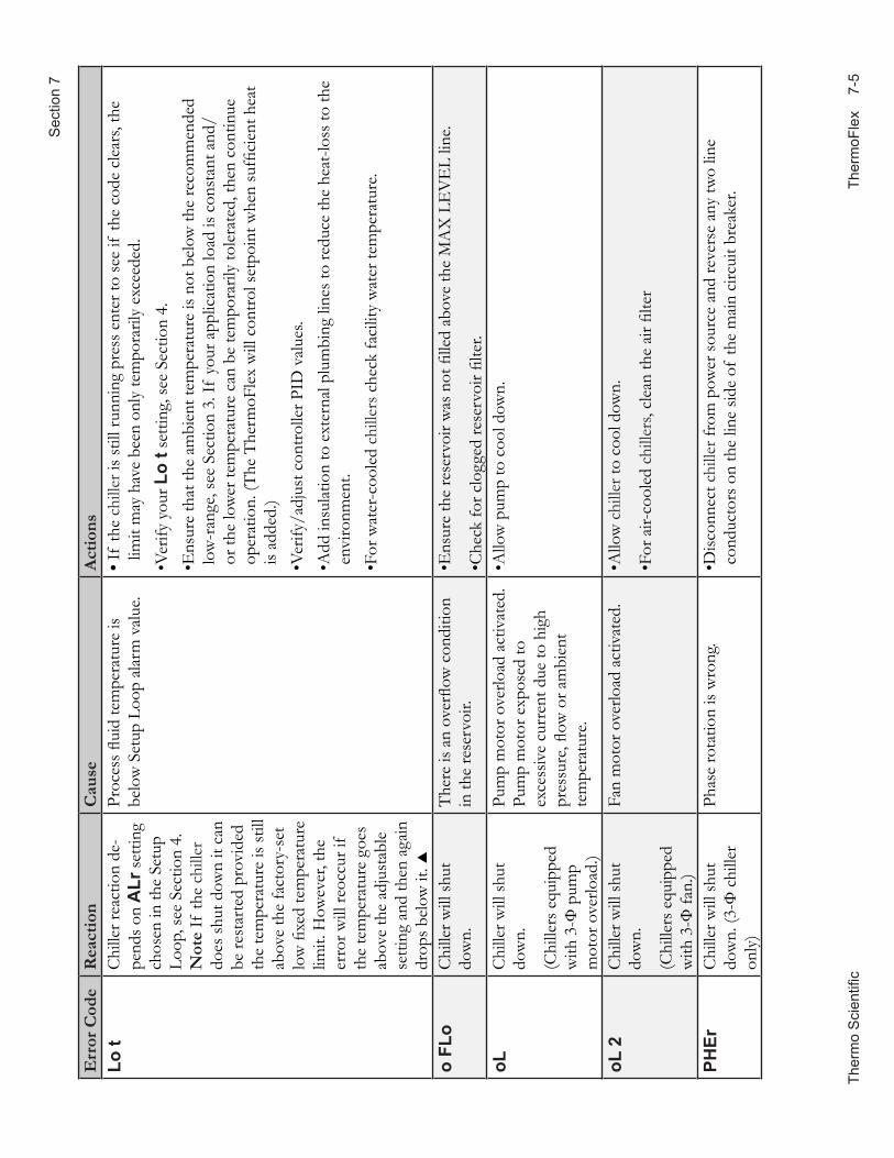
Ther
mo
Sci
entifi
c
The
rmoF
lex
7-
5
Sec
tion
7
Err
or C
ode
Rea
ctio
nC
ause
Act
ions
Lo t
Chi
ller r
eact
ion
de-
pend
s on
ALr
setti
ng
chos
en in
the
Setu
p Lo
op, s
ee S
ectio
n 4.
Not
e If
the
chill
er
does
shut
dow
n it
can
be re
star
ted
prov
ided
th
e te
mpe
ratu
re is
still
ab
ove
the
fact
ory-
set
low
fixe
d te
mpe
ratu
re
limit.
How
ever
, the
er
ror w
ill re
occu
r if
the
tem
pera
ture
goe
s ab
ove
the
adju
stab
le
setti
ng a
nd th
en a
gain
dr
ops b
elow
it.
Proc
ess fl
uid
tem
pera
ture
is
belo
w S
etup
Loo
p al
arm
val
ue.
•If
the
chill
er is
still
runn
ing
pres
s ent
er to
see
if th
e co
de c
lear
s, th
e lim
it m
ay h
ave
been
onl
y te
mpo
raril
y ex
ceed
ed.
•Ver
ify y
our L
o t s
ettin
g, se
e Se
ctio
n 4.
• Ens
ure
that
the
ambi
ent t
empe
ratu
re is
not
bel
ow th
e re
com
men
ded
low
-ran
ge, s
ee S
ectio
n 3.
If y
our a
pplic
atio
n lo
ad is
con
stan
t and
/or
the
low
er te
mpe
ratu
re c
an b
e te
mpo
raril
y to
lera
ted,
then
con
tinue
op
erat
ion.
(The
The
rmoF
lex
will
con
trol s
etpo
int w
hen
suffi
cien
t hea
t is
adde
d.)
•Ver
ify/a
djus
t con
trolle
r PID
val
ues.
• Add
insu
latio
n to
ext
erna
l plu
mbi
ng li
nes t
o re
duce
the
heat
-loss
to th
e en
viro
nmen
t.•F
or w
ater
-coo
led
chill
ers c
heck
faci
lity
wat
er te
mpe
ratu
re.
o FL
oC
hille
r will
shut
do
wn.
The
re is
an
over
flow
con
ditio
n in
the
rese
rvoi
r.•E
nsur
e th
e re
serv
oir w
as n
ot fi
lled
abov
e th
e M
AX
LE
VE
L lin
e.
•Che
ck fo
r clo
gged
rese
rvoi
r filte
r.oL
Chi
ller w
ill sh
ut
dow
n.
(Chi
llers
equ
ippe
d w
ith 3
-Ф p
ump
mot
or o
verlo
ad.)
Pum
p m
otor
ove
rload
act
ivat
ed.
Pum
p m
otor
exp
osed
to
exce
ssiv
e cu
rren
t due
to h
igh
pres
sure
, flow
or a
mbi
ent
tem
pera
ture
.
•Allo
w p
ump
to c
ool d
own.
oL 2
Chi
ller w
ill sh
ut
dow
n.
(Chi
llers
equ
ippe
d w
ith 3
-Ф fa
n.)
Fan
mot
or o
verlo
ad a
ctiv
ated
.•A
llow
chi
ller t
o co
ol d
own.
•For
air-
cool
ed c
hille
rs, c
lean
the
air fi
lter
PHEr
Chi
ller w
ill sh
ut
dow
n. (3
-Ф c
hille
r on
ly)
Phas
e ro
tatio
n is
wro
ng.
• Disc
onne
ct c
hille
r fro
m p
ower
sour
ce a
nd re
vers
e an
y tw
o lin
e co
nduc
tors
on
the
line
side
of th
e m
ain
circ
uit b
reak
er.
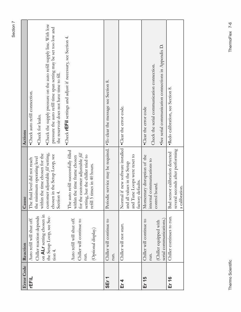
The
rmo
Sci
entifi
c
Ther
moF
lex
7-6
Sec
tion
7
Err
or C
ode
Rea
ctio
nC
ause
Act
ions
rEFi
LA
uto
refil
l will
shut
off.
Chi
ller r
eact
ion
depe
nds
on A
Lr se
tting
cho
sen
in
the
Setu
p Lo
op, s
ee S
ec-
tion
4.
Aut
o re
fill w
ill sh
ut o
ff.C
hille
r will
con
tinue
to
run.
(Opt
iona
l disp
lay.)
The
flui
d le
vel d
id n
ot re
ach
the
min
imum
ope
ratin
g le
vel
with
in th
e tim
e ch
osen
for t
he
cust
omer
adj
usta
ble
fill s
ettin
g,
chos
en in
the
Setu
p Lo
op, s
ee
Sect
ion
4.
The
aut
o re
fill s
ucce
ssfu
lly fi
lled
with
in th
e tim
e fr
ame
chos
en
for t
he c
usto
mer
adj
usta
ble
fill
setti
ng, b
ut th
e ch
iller
trie
d to
re
fill 5
tim
es in
40
hour
s.
•Che
ck a
uto
refil
l con
nect
ion.
•Che
ck fo
r lea
ks.
• Che
ck th
e su
pply
pre
ssur
e on
the
auto
refil
l sup
ply
line.
With
low
pr
essu
re th
e au
to re
fill t
ime
span
setti
ng m
ay b
e se
t too
low
and
th
e re
serv
oir d
oes n
ot h
ave
time
to fi
ll.
•Che
ck rE
Fil s
ettin
gs a
nd a
djus
t if
nece
ssar
y, se
e Se
ctio
n 4.
SEr 1
Chi
ller w
ill c
ontin
ue to
ru
n.Pe
riodi
c se
rvic
e m
ay b
e re
quire
d.•T
o cl
ear t
he m
essa
ge se
e Se
ctio
n 8.
Er 4
Chi
ller w
ill n
ot st
art.
Nor
mal
if n
ew so
ftwar
e in
stal
led
and
all v
alue
s in
the
Setu
p an
d Tu
ne L
oops
wer
e re
set t
o fa
ctor
y de
faul
ts.
•Cle
ar th
e er
ror c
ode.
Er 1
5C
hille
r will
con
tinue
to
run.
(Chi
ller e
quip
ped
with
se
rial c
omm
unic
atio
ns.)
Mom
enta
ry d
isrup
tion
of th
e in
tern
al c
omm
unic
atio
ns to
co
ntro
l boa
rd.
•Cle
ar th
e er
ror c
ode
Che
ck th
e se
rial c
omm
unic
atio
n co
nnec
tion.
•See
seria
l com
mun
icat
ion
conn
ectio
ns in
App
endi
x D
.
Er 1
6C
hille
r con
tinue
s to
run.
Bad
sens
or c
alib
ratio
n de
tect
ed
seve
ral s
econ
ds a
fter p
erfo
rmin
g a
calib
ratio
n.
•Red
o ca
libra
tion,
see
Sect
ion
8.
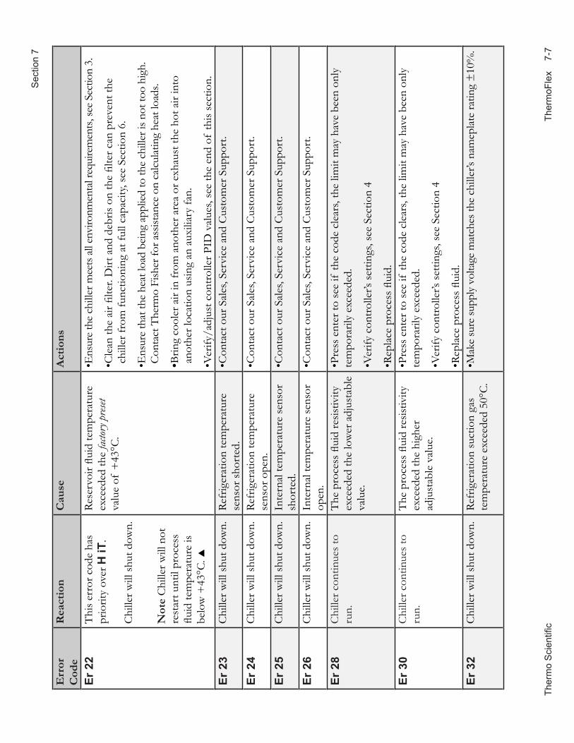
Ther
mo
Sci
entifi
c
The
rmoF
lex
7-
7
Sec
tion
7
Err
or
Cod
eR
eact
ion
Cau
seA
ctio
ns
Er 2
2T
his
erro
r cod
e ha
s pr
iorit
y ov
er H
iT.
Chi
ller w
ill s
hut d
own.
Not
e C
hille
r will
not
re
star
t unt
il pr
oces
s flu
id te
mpe
ratu
re is
be
low
+43
°C.
Rese
rvoi
r flui
d te
mpe
ratu
re
exce
eded
the
facto
ry p
reset
va
lue
of +
43°C
.
•Ens
ure
the
chill
er m
eets
all
envi
ronm
enta
l req
uire
men
ts, s
ee S
ectio
n 3.
• Cle
an th
e ai
r filte
r. D
irt a
nd d
ebris
on
the
filte
r can
pre
vent
the
chill
er fr
om fu
nctio
ning
at f
ull c
apac
ity, s
ee S
ectio
n 6.
• Ens
ure
that
the
heat
load
bei
ng a
pplie
d to
the
chill
er is
not
too
high
. C
onta
ct T
herm
o Fi
sher
for a
ssist
ance
on
calc
ulat
ing
heat
load
s.
•Brin
g co
oler
air
in fr
om a
noth
er a
rea
or e
xhau
st th
e ho
t air
into
an
othe
r loc
atio
n us
ing
an a
uxili
ary
fan.
•Ver
ify/a
djus
t con
trol
ler P
ID v
alue
s, se
e th
e en
d of
this
sect
ion.
Er
23
Chi
ller w
ill s
hut d
own.
Refr
iger
atio
n te
mpe
ratu
re
sens
or s
hort
ed.
•Con
tact
our
Sal
es, S
ervi
ce a
nd C
usto
mer
Sup
port
.
Er 2
4C
hille
r will
shu
t dow
n.Re
frig
erat
ion
tem
pera
ture
se
nsor
ope
n.•C
onta
ct o
ur S
ales
, Ser
vice
and
Cus
tom
er S
uppo
rt.
Er 2
5C
hille
r will
shu
t dow
n.In
tern
al te
mpe
ratu
re s
enso
r sh
orte
d.•C
onta
ct o
ur S
ales
, Ser
vice
and
Cus
tom
er S
uppo
rt.
Er 2
6C
hille
r will
shu
t dow
n.In
tern
al te
mpe
ratu
re s
enso
r op
en.
•Con
tact
our
Sal
es, S
ervi
ce a
nd C
usto
mer
Sup
port
.
Er 2
8C
hille
r con
tinue
s to
ru
n.T
he p
roce
ss fl
uid
resis
tivity
ex
ceed
ed th
e lo
wer
adj
usta
ble
valu
e.
•Pre
ss e
nter
to s
ee if
the
code
cle
ars,
the
limit
may
hav
e be
en o
nly
tem
pora
rily
exce
eded
.
•Ver
ify c
ontr
olle
r’s s
ettin
gs, s
ee S
ectio
n 4
•Rep
lace
pro
cess
flui
d.Er
30
Chi
ller c
ontin
ues
to
run.
The
pro
cess
flui
d re
sistiv
ity
exce
eded
the
high
er
adju
stab
le v
alue
.
•Pre
ss e
nter
to s
ee if
the
code
cle
ars,
the
limit
may
hav
e be
en o
nly
tem
pora
rily
exce
eded
.
•Ver
ify c
ontr
olle
r’s s
ettin
gs, s
ee S
ectio
n 4
•Rep
lace
pro
cess
flui
d.Er
32
Chi
ller w
ill s
hut d
own.
Refr
iger
atio
n su
ctio
n ga
s te
mpe
ratu
re e
xcee
ded
50°C
.•M
ake
sure
supp
ly v
olta
ge m
atch
es th
e ch
iller
’s na
mep
late
ratin
g ±
10%
.
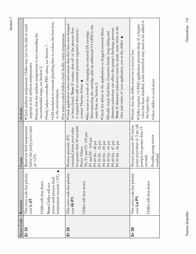
The
rmo
Sci
entifi
c
Ther
moF
lex
7-8
Sec
tion
7
Err
or C
ode
Rea
ctio
nC
ause
Act
ions
Er 3
3T
his e
rror
cod
e ha
s prio
rity
over
L o
T.
Chi
ller w
ill sh
ut d
own.
Not
e C
hille
r will
not
re
star
t unt
il pr
oces
s flui
d te
mpe
ratu
re e
xcee
ds +
2°C.
Rese
rvoi
r flui
d te
mpe
ratu
re
belo
w th
e fac
tory p
reset
valu
e of
+2°
C.
• Che
ck a
mbi
ent t
empe
ratu
re. C
hille
r may
not
to b
e ab
le to
reac
h se
tpoi
nt a
t low
am
bien
t tem
pera
ture
s.• E
nsur
e th
at th
e am
bien
t tem
pera
ture
is n
ot e
xcee
ding
the
reco
mm
ende
d ra
nge,
see
Sect
ion
3.•V
erify
/adj
ust c
ontro
ller P
ID v
alue
s, se
e Se
ctio
n 7.
• A
dd in
sula
tion
to e
xter
nal p
lum
bing
line
s to
redu
ce th
e he
at-lo
ss
to th
e en
viro
nmen
t.•F
or w
ater
-coo
led
chill
ers c
heck
faci
lity
wat
er te
mpe
ratu
re.
Er 3
5T
his e
rror
cod
e ha
s prio
rity
over
Hi P
1.
Chi
ller w
ill sh
ut d
own.
Proc
ess p
ress
ure
(P1)
ex
ceed
ed fa
ctory
pres
et va
lue
for g
reat
er th
an 3
0 se
cond
s. Pr
eset
Val
ues:
T0, T
1 an
d T5
- 105
psi
P1 a
nd P
2 - 1
05 p
si P3
60
Hz
- 48
psi
P3 5
0 H
z - 3
2 ps
i P4
60
Hz
- 85
psi
P4 5
0 H
z - 6
0 ps
i P5
60
Hz
- 87
psi
P5 5
0 H
z - 5
6 ps
i
• Che
ck a
pplic
atio
n va
lves
and
ens
ure
that
they
hav
e no
t cha
nged
or
bee
n cl
osed
. Not
e If
rout
ine
shut
-off
of
the
proc
ess fl
ow
is re
quire
d th
en a
dd a
n ex
tern
al p
ress
ure
regu
lato
r acc
esso
ry -
cont
act T
herm
o Fi
sher
. •M
ay o
ccur
as a
resu
lt of
cha
ngin
g th
e in
tern
al D
I car
tridg
e. D
iscon
nect
ing
the
cart
ridge
add
s an
addi
tiona
l 0.5
GPM
to th
e m
ain
flow,
see
Sect
ion
5.•C
heck
for d
ebris
in th
e ap
plic
atio
n or
clo
gged
ext
erna
l filte
rs.
• Dou
ble
chec
k flu
id li
nes.
Exc
essiv
e be
nds,
long
tubi
ng a
nd
diam
eter
redu
ctio
ns c
an a
ffec
t the
pum
p’s d
ischa
rge
pres
sure
. N
ote
If d
iam
eter
redu
ctio
ns m
ust b
e m
ade,
mak
e th
em a
t the
in
let a
nd o
utle
t of
your
app
licat
ion,
not
at t
he c
hille
r.
Er 3
6T
his e
rror
cod
e ha
s prio
rity
over
Lo
P1.
Chi
ller w
ill sh
ut d
own.
Proc
ess p
ress
ure
(P1)
bel
ow
factor
y pres
et lim
it of
2 p
si (a
ll pu
mps
) for
gre
ater
than
15
seco
nds.
Poss
ible
pum
p m
otor
ov
erlo
ad.
•Ens
ure
that
the
chill
er re
serv
oir i
s not
too
low.
• Chi
ller r
equi
res >
2 PS
IG a
pplic
atio
n pr
essu
re d
rop.
If a
byp
ass
valv
e ha
s bee
n in
stal
led,
som
e re
stric
tion
may
nee
d to
be
adde
d to
th
e by
pass
line
.•A
llow
chi
ller t
o co
ol d
own
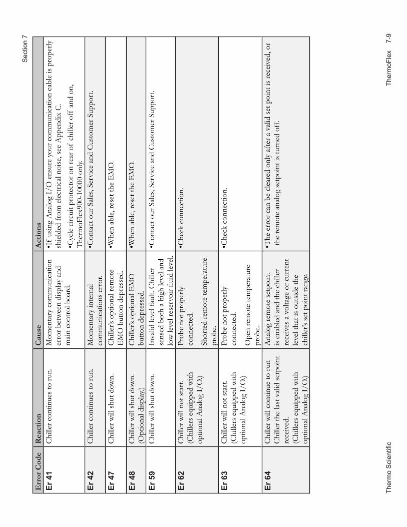
Ther
mo
Sci
entifi
c
The
rmoF
lex
7-
9
Sec
tion
7
Err
or C
ode
Rea
ctio
nC
ause
Act
ions
Er 4
1C
hille
r con
tinue
s to
run.
Mom
enta
ry c
omm
unic
atio
n er
ror b
etw
een
disp
lay a
nd
mai
n co
ntro
l boa
rd.
•If
usin
g A
nalo
g I/
O e
nsur
e yo
ur c
omm
unic
atio
n ca
ble
is pr
oper
ly
shie
lded
from
ele
ctric
al n
oise
, see
App
endi
x C.
•Cyc
le c
ircui
t pro
tect
or o
n re
ar o
f ch
iller
off
and
on,
T
herm
oFle
x900
-100
00 o
nly.
Er 4
2C
hille
r con
tinue
s to
run.
Mom
enta
ry in
tern
al
com
mun
icat
ions
err
or.
•Con
tact
our
Sal
es, S
ervi
ce a
nd C
usto
mer
Sup
port
.
Er 4
7C
hille
r will
shut
dow
n.C
hille
r’s o
ptio
nal r
emot
e E
MO
but
ton
depr
esse
d.•W
hen
able
, res
et th
e E
MO
.
Er 4
8C
hille
r will
shut
dow
n.(O
ptio
nal d
isplay
.)C
hille
r’s o
ptio
nal E
MO
bu
tton
depr
esse
d.•W
hen
able
, res
et th
e E
MO
.
Er 5
9C
hille
r will
shut
dow
n.In
valid
leve
l fau
lt. C
hille
r se
nsed
bot
h a
high
leve
l and
lo
w le
vel r
eser
voir
fluid
leve
l.
•Con
tact
our
Sal
es, S
ervi
ce a
nd C
usto
mer
Sup
port
.
Er 6
2C
hille
r will
not
star
t.(C
hille
rs e
quip
ped
with
op
tiona
l Ana
log
I/O
.)
Prob
e no
t pro
perly
co
nnec
ted.
Shor
ted
rem
ote
tem
pera
ture
pr
obe.
•Che
ck c
onne
ctio
n.
Er 6
3C
hille
r will
not
star
t.(C
hille
rs e
quip
ped
with
op
tiona
l Ana
log
I/O
.)
Prob
e no
t pro
perly
co
nnec
ted.
Ope
n re
mot
e te
mpe
ratu
re
prob
e.
•Che
ck c
onne
ctio
n.
Er 6
4C
hille
r will
con
tinue
to ru
n C
hille
r the
last
val
id se
tpoi
nt
rece
ived
. (C
hille
rs e
quip
ped
with
op
tiona
l Ana
log
I/O
.)
Ana
log
rem
ote
setp
oint
is
enab
led
and
the
chill
er
rece
ives
a v
olta
ge o
r cur
rent
le
vel t
hat i
s out
side
the
chill
er’s
set p
oint
rang
e.
• The
err
or c
an b
e cl
eare
d on
ly a
fter a
val
id se
t poi
nt is
rece
ived
, or
the
rem
ote
anal
og se
tpoi
nt is
turn
ed o
ff.
Section 7
7-10 ThermoFlex Thermo Scientific
Checklist Chiller will not start Check electrical connections.
For first time use, please refer to the quick start instructions included with your chiller or the copy in this manual. The manual's copy follows the Table of Contents.
Check the controller for error codes, see Error Codes in this Section.
Ensure the optional GFCI breaker located on the rear of the chiller is in the up position.
For ThermoFlex900 - 10000 chillers ensure the circuit protector is in the on ( I ) position.
Make sure supply voltage is connected and matches the chiller's nameplate rating ±10%
No display on controller or display is 8888 For ThermoFlex900 - 10000 recycle the circuit protector on the rear of the chiller.
Clearing Error CodesNote the code in case it clears before you are done troubleshooting.
If desired, silence the alarm by pressing the up or down arrow key.
If the chiller shut down, the controller will continue to flash the error code. Press enter to clear the display and silence any alarm. Refer to Error Codes in this Section. Once the cause of the shut down is identified and corrected, start the chiller. If the cause was not corrected the error code will reappear.
If the chiller is still running, press enter to see if the code clears, a limit may have been only temporarily exceeded. If the error code does not clear press until the display flashes between the error code and the temperature and then press enter. If the code still does not clear refer to Error Codes in this Section.
Section 7
ThermoFlex 7-11 Thermo Scientific
Chiller shuts downEnsure button wasn't accidently pressed.
Ensure the optional GFCI breaker located on the rear of the chiller is in the up position.
For ThermoFlex900 - 10000 chillers ensure the circuit protector is in the on ( I ) position.
Check the controller for error codes, see Error Codes in this Section.
The chiller is designed to shut down if not properly primed, refer to Section 3 for priming instructions.
Make sure supply voltage is connected and matches the chiller's nameplate rating ±10%.
Restart the chiller.
Inadequate pump pressureEnsure any user installed in-line valves are in the desired position.
Ensure the chiller’s process fluid outlet is connected to the application’s fluid inlet and not the application’s fluid outlet, see Section 3.
Ensure all connections are secure and that the proper sealant/lubricant for the fitting material is used.
Keep the distance between the chiller and the instrument being cooled as short as possible.
Ensure tubing is straight and without bends. If diameter reductions are required, make them at the inlet and outlet of your application, not at the chiller.
Chiller will not circulate process fluid Check the reservoir level. Fill, if necessary.
Ensure the reservoir bag filter is not clogged.
Check the application for restrictions in the cooling lines.
Chiller requires >3 PSIG application pressure drop. If a bypass valve has been installed add some restriction to the bypass line.
The pump motor overloaded. The pump's internal overtemperature overcurrent device will shut off the pump causing the flow to stop. This can be caused by low fluid, debris in system, operating chiller in a high ambient temperature condition or excessively confined space. Allow time for the motor to cool down.
Make sure supply voltage matches the chiller's nameplate rating ±10%.
Section 7
7-12 ThermoFlex Thermo Scientific
Inadequate temperature controlVerify the setpoint.
If the chiller is over-cooling, recycle the power.
Make sure the condenser/air filter is free of dust and debris.
Check the fluid concentration, see Section 3.
Ensure chiller installation complies with site requirements, see Section 3.
Make sure supply voltage matches chiller nameplate rating ±10%.
For ThermoFlex900 - 5000 global voltage chillers ensure the chiller is properly configured, see Appendix B.
If the temperature continues to rise, make sure your application's heat load does not exceed the rated specifications.
Check for high thermal gradients (e.g., the application load is being turned on and off or rapidly changing).
Verify/adjust controller PID values, see next page.
Chiller vibrationThe optional pressure relief valve setting may be the cause. Change the pressure setting ± 5 psi to eliminate the vibration.
Please contact Thermo Fisher Scientific Sales Service and Customer Support if you need any additional information, see this manual's inside cover for contact instructions.
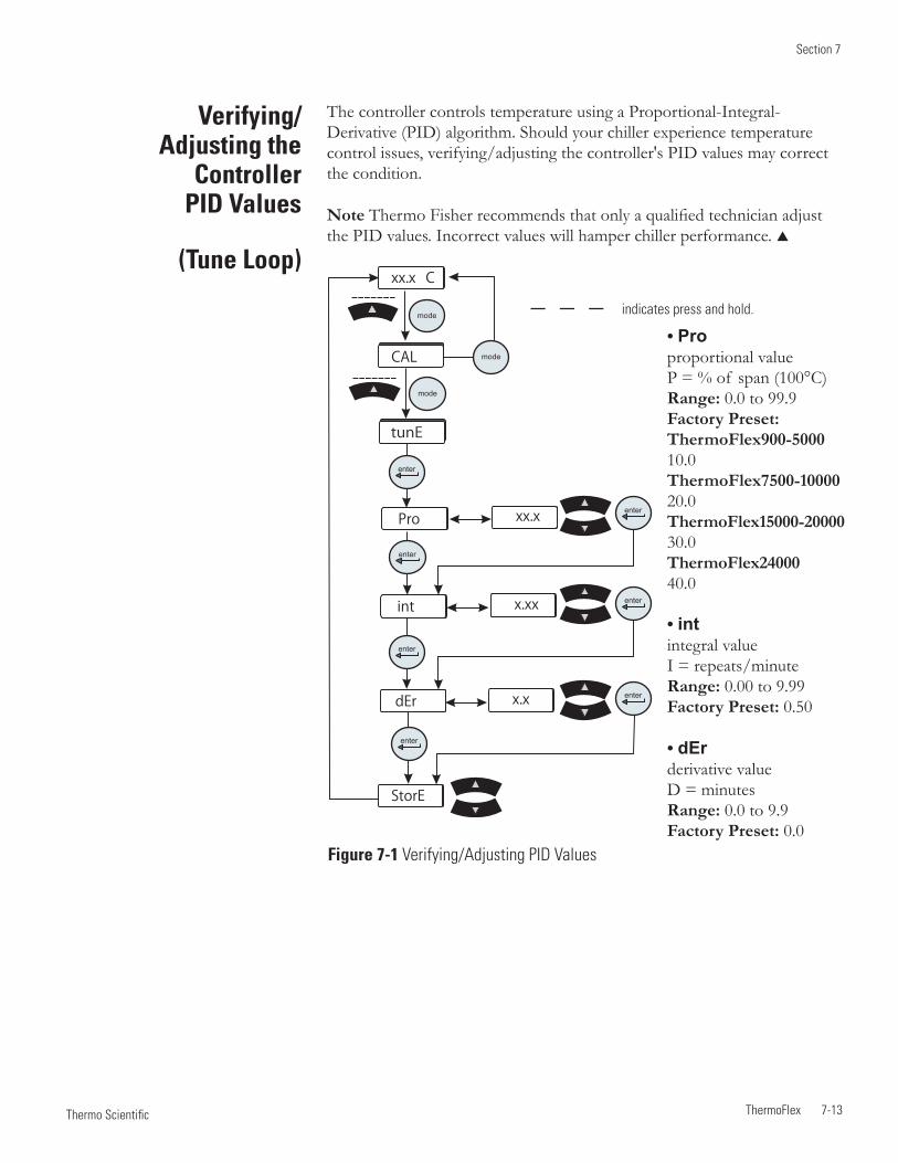
Section 7
ThermoFlex 7-13 Thermo Scientific
Verifying/ Adjusting the
Controller PID Values
(Tune Loop)
The controller controls temperature using a Proportional-Integral-Derivative (PID) algorithm. Should your chiller experience temperature control issues, verifying/adjusting the controller's PID values may correct the condition.
Note Thermo Fisher recommends that only a qualified technician adjust the PID values. Incorrect values will hamper chiller performance.
• Pro proportional value P = % of span (100°C) Range: 0.0 to 99.9 Factory Preset: ThermoFlex900-5000 10.0 ThermoFlex7500-10000 20.0 ThermoFlex15000-20000 30.0 ThermoFlex24000 40.0 • int integral value I = repeats/minute Range: 0.00 to 9.99 Factory Preset: 0.50
• dEr derivative value D = minutes Range: 0.0 to 9.9 Factory Preset: 0.0
Figure 7-1 Verifying/Adjusting PID Values
indicates press and hold.
tunE
Pro
int
dEr
enter
StorE
xx.x C
mode
mode
CAL mode
xx.x
xx.x
xx.x
xx.x
x.xx
x.x
enter
enter
enter
enter
enter
enter

Section 7
7-14 ThermoFlex Thermo Scientific
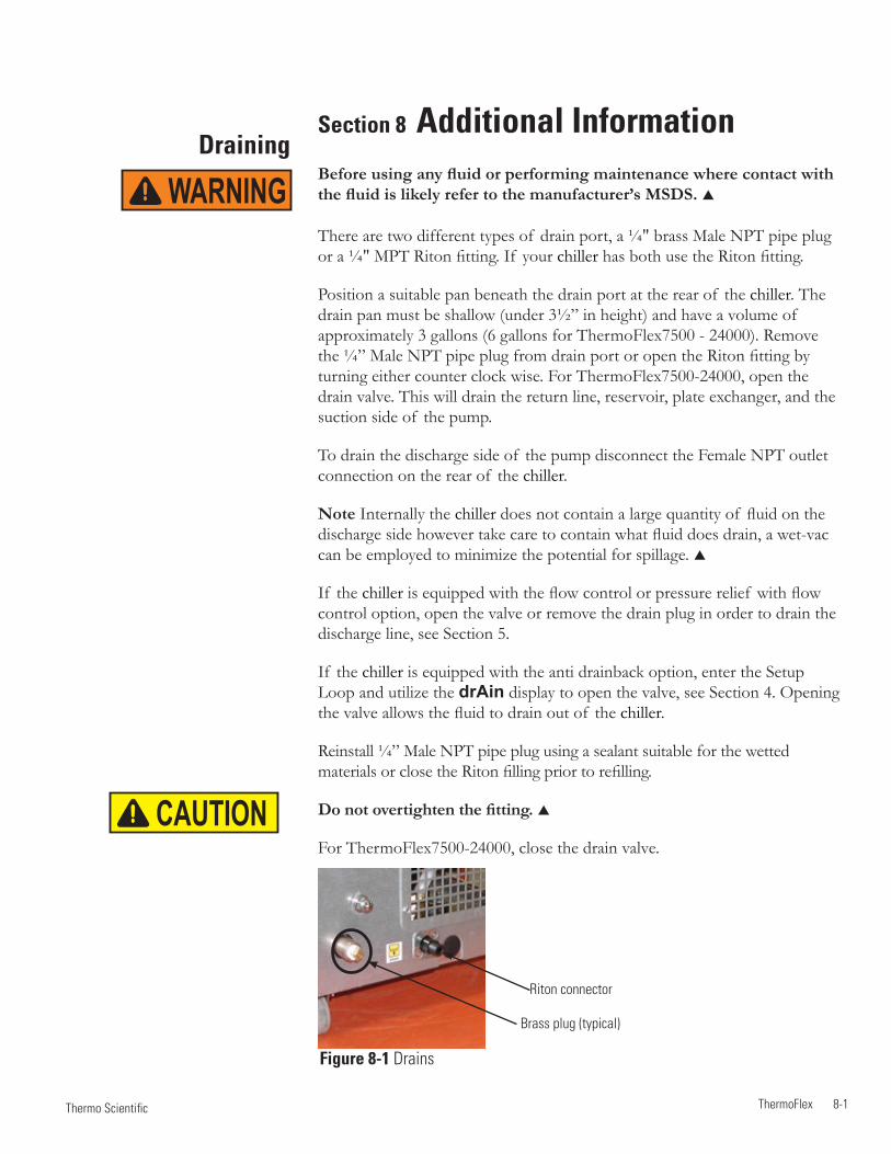
ThermoFlex 8-1 Thermo Scientific
DrainingSection 8 Additional InformationBefore using any fluid or performing maintenance where contact with the fluid is likely refer to the manufacturer’s MSDS.
There are two different types of drain port, a ¼" brass Male NPT pipe plug or a ¼" MPT Riton fitting. If your chiller has both use the Riton fitting.
Position a suitable pan beneath the drain port at the rear of the chiller. The drain pan must be shallow (under 3½” in height) and have a volume of approximately 3 gallons (6 gallons for ThermoFlex7500 - 24000). Remove the ¼” Male NPT pipe plug from drain port or open the Riton fitting by turning either counter clock wise. For ThermoFlex7500-24000, open the drain valve. This will drain the return line, reservoir, plate exchanger, and the suction side of the pump.
To drain the discharge side of the pump disconnect the Female NPT outlet connection on the rear of the chiller.
Note Internally the chiller does not contain a large quantity of fluid on the discharge side however take care to contain what fluid does drain, a wet-vac can be employed to minimize the potential for spillage.
If the chiller is equipped with the flow control or pressure relief with flow control option, open the valve or remove the drain plug in order to drain the discharge line, see Section 5.
If the chiller is equipped with the anti drainback option, enter the Setup Loop and utilize the drAin display to open the valve, see Section 4. Opening the valve allows the fluid to drain out of the chiller.
Reinstall ¼” Male NPT pipe plug using a sealant suitable for the wetted materials or close the Riton filling prior to refilling.
Do not overtighten the fitting.
For ThermoFlex7500-24000, close the drain valve.
WARNING
Figure 8-1 Drains
Brass plug (typical)
Riton connector
CAUTION
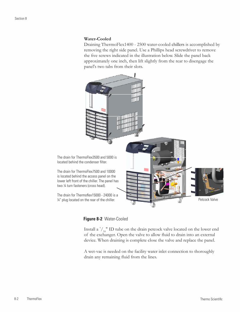
Section 8
8-2 ThermoFlex Thermo Scientific
Water-Cooled Draining ThermoFlex1400 - 2500 water-cooled chillers is accomplished by removing the right side panel. Use a Phillips head screwdriver to remove the five screws indicated in the illustration below. Slide the panel back approximately one inch, then lift slightly from the rear to disengage the panel's two tabs from their slots.
Petcock Valve
The drain for ThermoFlex3500 and 5000 is located behind the condenser filter.
The drain for ThermoFlex7500 and 10000 is located behind the access panel on the lower left front of the chiller. The panel has two ¼ turn fasteners (cross head).
The drain for Thermoflex15000 - 24000 is a ¼" plug located on the rear of the chiller.
Figure 8-2 Water-Cooled
Install a 7/16" ID tube on the drain petcock valve located on the lower end of the exchanger. Open the valve to allow fluid to drain into an external device. When draining is complete close the valve and replace the panel.
A wet-vac is needed on the facility water inlet connection to thoroughly drain any remaining fluid from the lines.
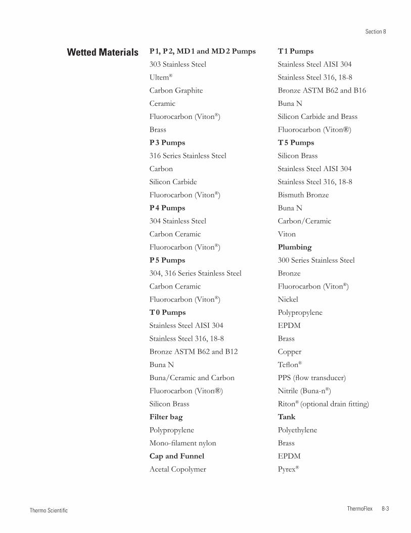
Section 8
ThermoFlex 8-3 Thermo Scientific
Wetted Materials P 1, P 2, MD 1 and MD 2 Pumps
303 Stainless Steel
Ultem®
Carbon Graphite
Ceramic
Fluorocarbon (Viton®)
Brass
P 3 Pumps
316 Series Stainless Steel
Carbon
Silicon Carbide
Fluorocarbon (Viton®)
P 4 Pumps
304 Stainless Steel
Carbon Ceramic
Fluorocarbon (Viton®)
P 5 Pumps
304, 316 Series Stainless Steel
Carbon Ceramic
Fluorocarbon (Viton®)
T 0 Pumps
Stainless Steel AISI 304
Stainless Steel 316, 18-8
Bronze ASTM B62 and B12
Buna N
Buna/Ceramic and Carbon
Fluorocarbon (Viton®)
Silicon Brass
Filter bag
Polypropylene
Mono-filament nylon
Cap and Funnel
Acetal Copolymer
T 1 Pumps
Stainless Steel AISI 304
Stainless Steel 316, 18-8
Bronze ASTM B62 and B16
Buna N
Silicon Carbide and Brass
Fluorocarbon (Viton®)
T 5 Pumps
Silicon Brass
Stainless Steel AISI 304
Stainless Steel 316, 18-8
Bismuth Bronze
Buna N
Carbon/Ceramic
Viton
Plumbing
300 Series Stainless Steel
Bronze
Fluorocarbon (Viton®)
Nickel
Polypropylene
EPDM
Brass
Copper
Teflon®
PPS (flow transducer)
Nitrile (Buna-n®)
Riton® (optional drain fitting)
Tank
Polyethylene
Brass
EPDM
Pyrex®
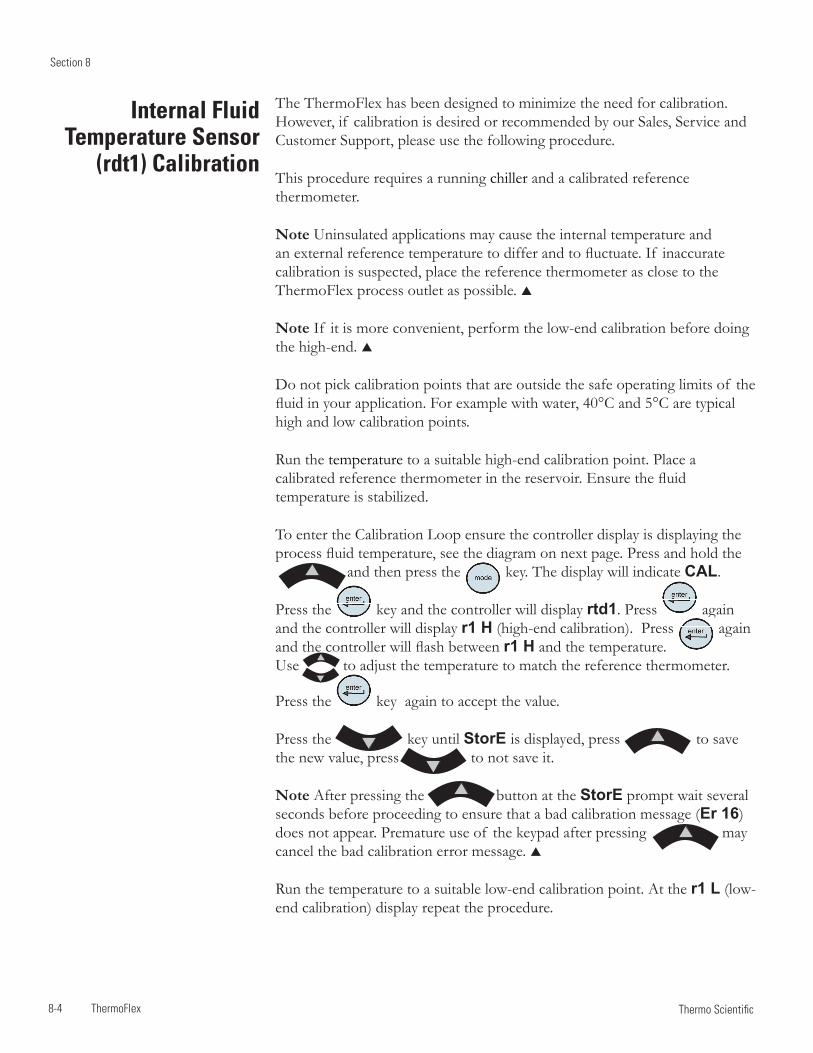
Section 8
8-4 ThermoFlex Thermo Scientific
Internal Fluid Temperature Sensor
(rdt1) Calibration
The ThermoFlex has been designed to minimize the need for calibration. However, if calibration is desired or recommended by our Sales, Service and Customer Support, please use the following procedure.
This procedure requires a running chiller and a calibrated reference thermometer.
Note Uninsulated applications may cause the internal temperature and an external reference temperature to differ and to fluctuate. If inaccurate calibration is suspected, place the reference thermometer as close to the ThermoFlex process outlet as possible.
Note If it is more convenient, perform the low-end calibration before doing the high-end.
Do not pick calibration points that are outside the safe operating limits of the fluid in your application. For example with water, 40°C and 5°C are typical high and low calibration points.
Run the temperature to a suitable high-end calibration point. Place a calibrated reference thermometer in the reservoir. Ensure the fluid temperature is stabilized.
To enter the Calibration Loop ensure the controller display is displaying the process fluid temperature, see the diagram on next page. Press and hold the and then press the key. The display will indicate CAL.
Press the key and the controller will display rtd1. Press again and the controller will display r1 H (high-end calibration). Press again and the controller will flash between r1 H and the temperature. Use to adjust the temperature to match the reference thermometer.
Press the key again to accept the value.
Press the key until StorE is displayed, press to save the new value, press to not save it.
Note After pressing the button at the StorE prompt wait several seconds before proceeding to ensure that a bad calibration message (Er 16) does not appear. Premature use of the keypad after pressing may cancel the bad calibration error message.
Run the temperature to a suitable low-end calibration point. At the r1 L (low-end calibration) display repeat the procedure.
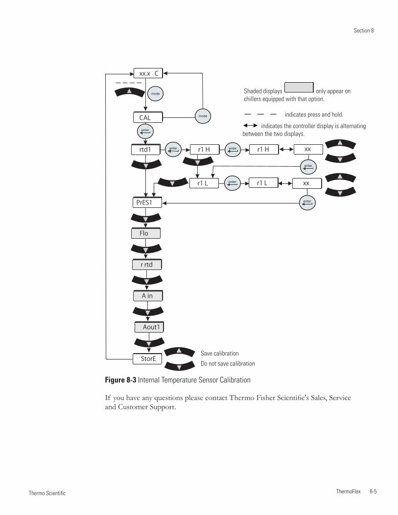
Section 8
ThermoFlex 8-5 Thermo Scientific
xx.x
xx.x
xx
xx
r1 H
r1 L
r1 H
r1 L
xx.x C
mode
rtd1
PrES1
Flo
r rtd
A in
Aout1
CALenter
enter enter
enter
enter
enter
StorE
mode
indicates the controller display is alternating between the two displays.
indicates press and hold.
Figure 8-3 Internal Temperature Sensor Calibration
Shaded displays only appear on chillers equipped with that option.
If you have any questions please contact Thermo Fisher Scientific's Sales, Service and Customer Support.
Save calibration
Do not save calibration
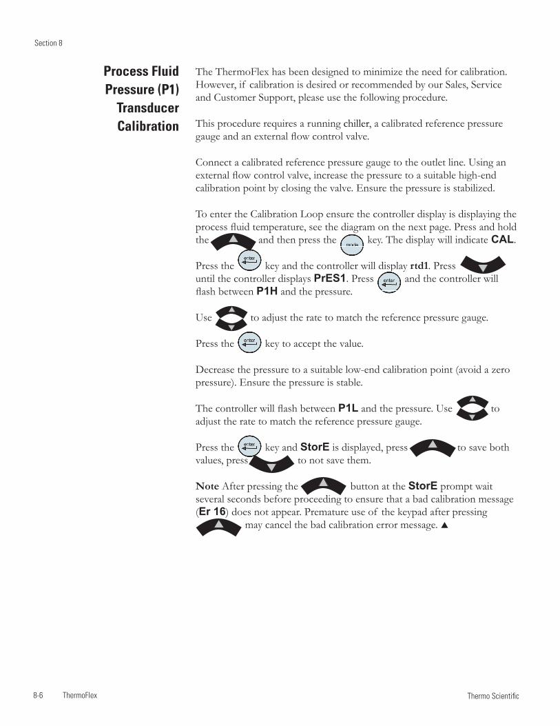
Section 8
8-6 ThermoFlex Thermo Scientific
Process Fluid Pressure (P1)
Transducer Calibration
The ThermoFlex has been designed to minimize the need for calibration. However, if calibration is desired or recommended by our Sales, Service and Customer Support, please use the following procedure.
This procedure requires a running chiller, a calibrated reference pressure gauge and an external flow control valve.
Connect a calibrated reference pressure gauge to the outlet line. Using an external flow control valve, increase the pressure to a suitable high-end calibration point by closing the valve. Ensure the pressure is stabilized.
To enter the Calibration Loop ensure the controller display is displaying the process fluid temperature, see the diagram on the next page. Press and hold the and then press the key. The display will indicate CAL.
Press the key and the controller will display rtd1. Press until the controller displays PrES1. Press and the controller will flash between P1H and the pressure.
Use to adjust the rate to match the reference pressure gauge.
Press the key to accept the value.
Decrease the pressure to a suitable low-end calibration point (avoid a zero pressure). Ensure the pressure is stable.
The controller will flash between P1L and the pressure. Use to adjust the rate to match the reference pressure gauge.
Press the key and StorE is displayed, press to save both values, press to not save them.
Note After pressing the button at the StorE prompt wait several seconds before proceeding to ensure that a bad calibration message (Er 16) does not appear. Premature use of the keypad after pressing may cancel the bad calibration error message.
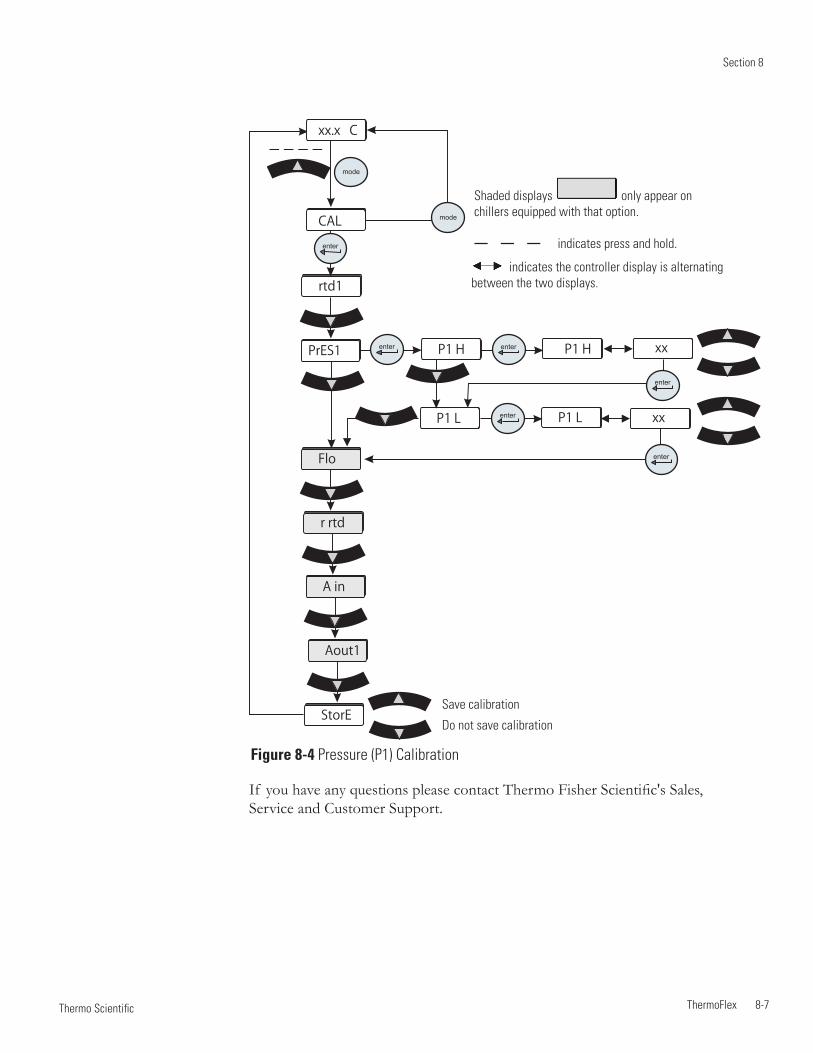
Section 8
ThermoFlex 8-7 Thermo Scientific
xx.x
xx.x
xx
xx
P1 H
P1 L
P1 H
P1 L
xx.x C
mode
rtd1
PrES1
Flo
r rtd
A in
Aout1
CALenter
enter enter
enter
enter
enter
StorE
mode
If you have any questions please contact Thermo Fisher Scientific's Sales, Service and Customer Support.
Figure 8-4 Pressure (P1) Calibration
indicates the controller display is alternating between the two displays.
indicates press and hold.
Shaded displays only appear on chillers equipped with that option.
Save calibration
Do not save calibration
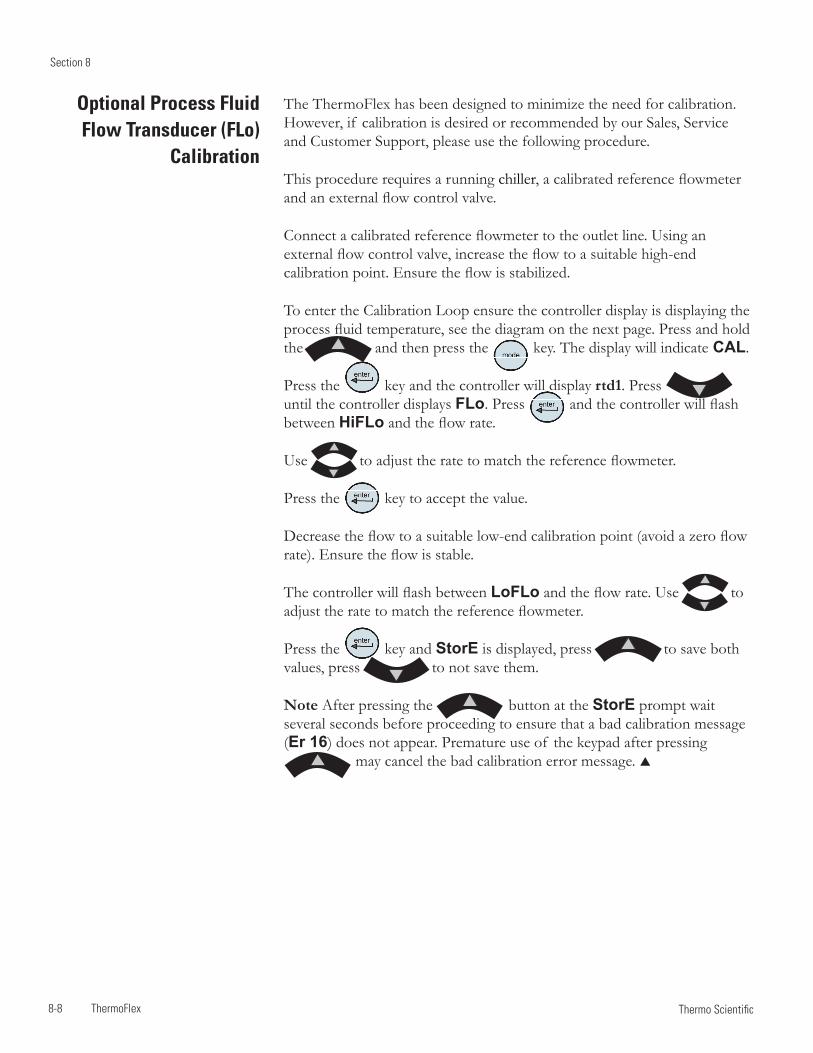
Section 8
8-8 ThermoFlex Thermo Scientific
Optional Process Fluid Flow Transducer (FLo)
Calibration
The ThermoFlex has been designed to minimize the need for calibration. However, if calibration is desired or recommended by our Sales, Service and Customer Support, please use the following procedure.
This procedure requires a running chiller, a calibrated reference flowmeter and an external flow control valve.
Connect a calibrated reference flowmeter to the outlet line. Using an external flow control valve, increase the flow to a suitable high-end calibration point. Ensure the flow is stabilized.
To enter the Calibration Loop ensure the controller display is displaying the process fluid temperature, see the diagram on the next page. Press and hold the and then press the key. The display will indicate CAL.
Press the key and the controller will display rtd1. Press until the controller displays FLo. Press and the controller will flash between HiFLo and the flow rate.
Use to adjust the rate to match the reference flowmeter.
Press the key to accept the value.
Decrease the flow to a suitable low-end calibration point (avoid a zero flow rate). Ensure the flow is stable.
The controller will flash between LoFLo and the flow rate. Use to adjust the rate to match the reference flowmeter.
Press the key and StorE is displayed, press to save both values, press to not save them.
Note After pressing the button at the StorE prompt wait several seconds before proceeding to ensure that a bad calibration message (Er 16) does not appear. Premature use of the keypad after pressing may cancel the bad calibration error message.
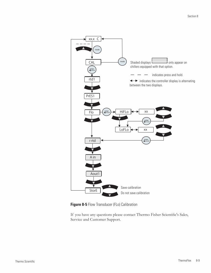
Section 8
ThermoFlex 8-9 Thermo Scientific
If you have any questions please contact Thermo Fisher Scientific's Sales, Service and Customer Support.
Figure 8-5 Flow Transducer (FLo) Calibration
indicates the controller display is alternating between the two displays.
indicates press and hold.
xx.x C
mode
rtd1
PrES1
Flo
r rtd
A in
Aout1
CALenter
StorE
xx.x
xx.x
xx
xx
HiFLo
LoFLo
enter
enter
enter
mode Shaded displays only appear on chillers equipped with that option.
Save calibration
Do not save calibration
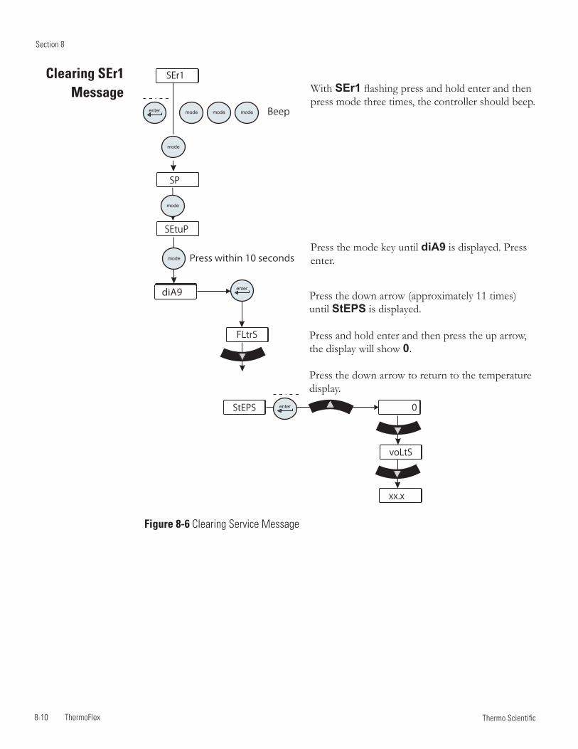
Section 8
8-10 ThermoFlex Thermo Scientific
enter
enter
SEtuP
mode modemode
diA9
mode
mode
SP
mode Press within 10 seconds
FLtrS
StEPS 0enter
voLtS
xx.x
Beep
SEr1Clearing SEr1 Message
Press the down arrow (approximately 11 times) until StEPS is displayed.
Press and hold enter and then press the up arrow, the display will show 0.
Press the down arrow to return to the temperature display.
With SEr1 flashing press and hold enter and then press mode three times, the controller should beep.
Press the mode key until diA9 is displayed. Press enter.
Figure 8-6 Clearing Service Message
Section 8
ThermoFlex 8-11 Thermo Scientific
CAUTION
CAUTION
Decommissioning/ Disposal
Laboratory Grade Ethylene glycol (EG) is poisonous and flammable. Before disposing refer to the manufacturer’s most current MSDS for handling precautions.
Decommissioning must be performed only by qualified dealer using certified equipment. All prevailing regulations must be followed.
Consider decommissioning the chiller when:
• Itfailstomaintaindesiredspecifications
• It no longer meets safety standards
• It is beyond repair for its age and worth
Refrigerant and compressor oil must be recovered from equipment before disposal.
Note Keep in mind any impact your application may have had on the chiller.
Direct questions about chiller decommissioning or disposal to our Sales, Service and Customer Support.
Handle and dispose in accordance with the manufacturers specification and/or the MSDS for the material used.
WARNING
Shipment Storage
Follow the manufacturer's MSDS instructions if decontamination is required.
Transporting and/or storing the chiller in near or below freezing temperatures requires draining, see Draining in this Section. Store the chiller in the temperature range of -25°C to 60°C (with packaging), and <80% relative humidity.
If the chiller is stored for more than 90 days it must be flushed with clean fluid before operating.
CAUTION
CAUTION
CAUTION

Section 8
8-12 ThermoFlex Thermo Scientific
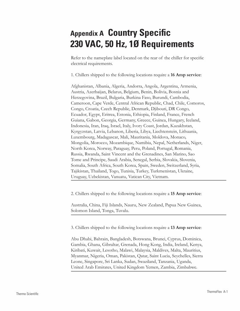
ThermoFlex A-1 Thermo Scientific
Appendix A Country Specific 230 VAC, 50 Hz, 1Ø RequirementsRefer to the nameplate label located on the rear of the chiller for specific electrical requirements.
1. Chillers shipped to the following locations require a 16 Amp service:
Afghanistan, Albania, Algeria, Andorra, Angola, Argentina, Armenia,Austria, Azerbaijan, Belarus, Belgium, Benin, Bolivia, Bosnia andHerzegovina, Brazil, Bulgaria, Burkina Faso, Burundi, Cambodia,Cameroon, Cape Verde, Central African Republic, Chad, Chile, Comoros,Congo, Croatia, Czech Republic, Denmark, Djibouti, DR Congo,Ecuador, Egypt, Eritrea, Estonia, Ethiopia, Finland, France, FrenchGuiana, Gabon, Georgia, Germany, Greece, Guinea, Hungary, Iceland,Indonesia, Iran, Iraq, Israel, Italy, Ivory Coast, Jordan, Kazakhstan,Kyrgyzstan, Latvia, Lebanon, Liberia, Libya, Liechtenstein, Lithuania,Luxembourg, Madagascar, Mali, Mauritania, Moldova, Monaco,Mongolia, Morocco, Mozambique, Namibia, Nepal, Netherlands, Niger,North Korea, Norway, Paraguay, Peru, Poland, Portugal, Romania,Russia, Rwanda, Saint Vincent and the Grenadines, San Marino, SaoTome and Principe, Saudi Arabia, Senegal, Serbia, Slovakia, Slovenia,Somalia, South Africa, South Korea, Spain, Sweden, Switzerland, Syria,Tajikistan, Thailand, Togo, Tunisia, Turkey, Turkmenistan, Ukraine,Uruguay, Uzbekistan, Vanuatu, Vatican City, Vietnam.
2. Chillers shipped to the following locations require a 15 Amp service:
Australia, China, Fiji Islands, Nauru, New Zealand, Papua New Guinea,Solomon Island, Tonga, Tuvalu.
3. Chillers shipped to the following locations require a 13 Amp service:
Abu Dhabi, Bahrain, Bangladesh, Botswana, Brunei, Cyprus, Dominica,Gambia, Ghana, Gibraltar, Grenada, Hong Kong, India, Ireland, Kenya,Kiribati, Kuwait, Lesotho, Malawi, Malaysia, Maldives, Malta, Mauritius,Myanmar, Nigeria, Oman, Pakistan, Qatar, Saint Lucia, Seychelles, SierraLeone, Singapore, Sri Lanka, Sudan, Swaziland, Tanzania, Uganda,United Arab Emirates, United Kingdom Yemen, Zambia, Zimbabwe.
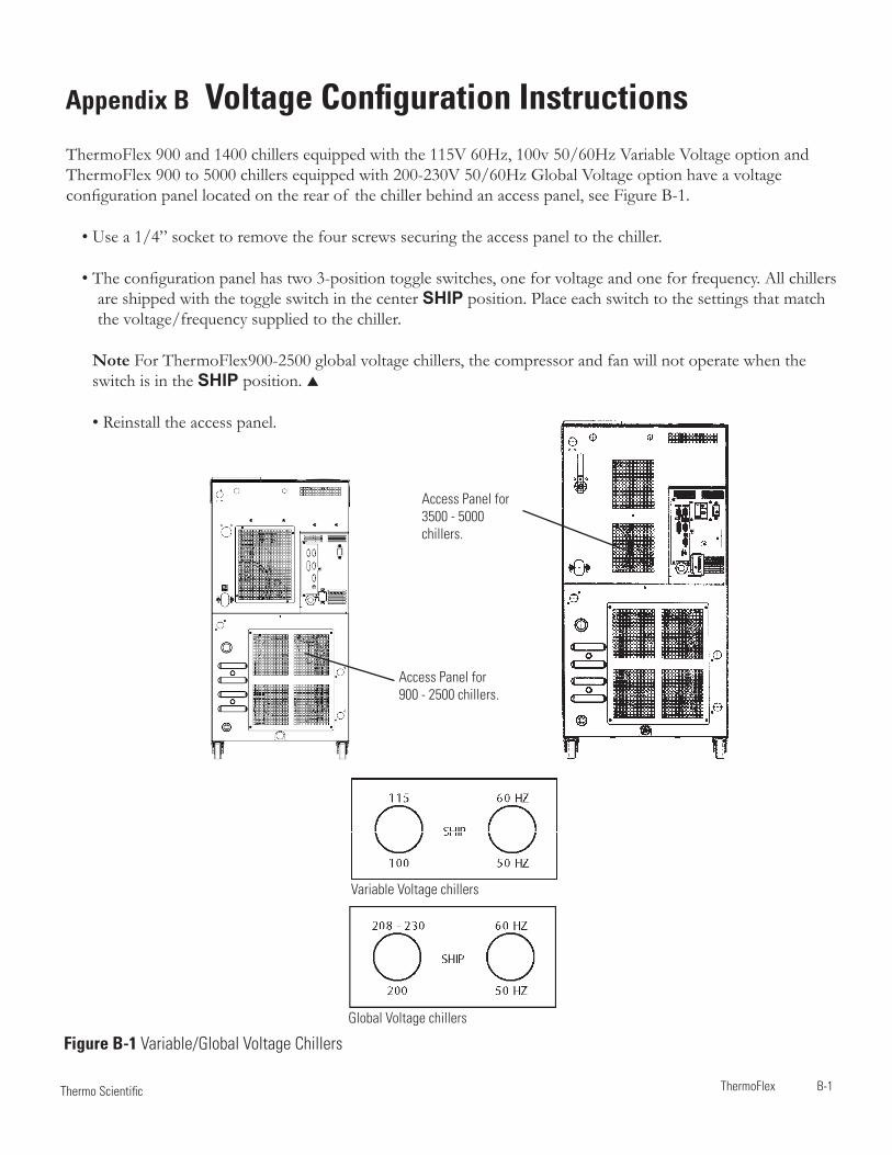
ThermoFlex B-1 Thermo Scientific
Appendix B Voltage Configuration InstructionsThermoFlex 900 and 1400 chillers equipped with the 115V 60Hz, 100v 50/60Hz Variable Voltage option and ThermoFlex 900 to 5000 chillers equipped with 200-230V 50/60Hz Global Voltage option have a voltage configuration panel located on the rear of the chiller behind an access panel, see Figure B-1.
• Use a 1/4” socket to remove the four screws securing the access panel to the chiller.
• The configuration panel has two 3-position toggle switches, one for voltage and one for frequency. All chillers are shipped with the toggle switch in the center SHIP position. Place each switch to the settings that match the voltage/frequency supplied to the chiller.
Note For ThermoFlex900-2500 global voltage chillers, the compressor and fan will not operate when the switch is in the SHIP position.
• Reinstall the access panel.
Access Panel for 900 - 2500 chillers.
Access Panel for 3500 - 5000 chillers.
Variable Voltage chillers
Global Voltage chillers
Figure B-1 Variable/Global Voltage Chillers
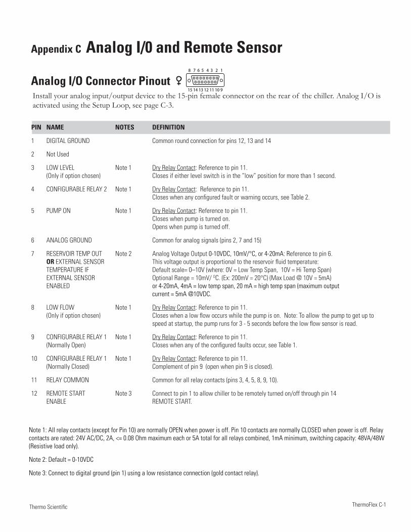
ThermoFlex C-1 Thermo Scientific
Appendix C Analog I/0 and Remote Sensor
Analog I/O Connector PinoutInstall your analog input/output device to the 15-pin female connector on the rear of the chiller. Analog I/O is activated using the Setup Loop, see page C-3.
PIN NAME NOTES DEFINITION
1 DIGITAL GROUND Common round connection for pins 12, 13 and 14
2 Not Used
3 LOW LEVEL Note 1 Dry Relay Contact: Reference to pin 11. (Only if option chosen) Closes if either level switch is in the “low” position for more than 1 second.
4 CONFIGURABLE RELAY 2 Note 1 Dry Relay Contact: Reference to pin 11. Closes when any configured fault or warning occurs, see Table 2.
5 PUMP ON Note 1 Dry Relay Contact: Reference to pin 11. Closes when pump is turned on. Opens when pump is turned off.
6 ANALOG GROUND Common for analog signals (pins 2, 7 and 15)
7 RESERVOIR TEMP OUT Note 2 Analog Voltage Output 0-10VDC, 10mV/°C, or 4-20mA: Reference to pin 6. OR EXTERNAL SENSOR This voltage output is proportional to the reservoir fluid temperature: TEMPERATURE IF Default scale= 0–10V (where: 0V = Low Temp Span, 10V = Hi Temp Span) EXTERNAL SENSOR Optional Range = 10mV/ OC. (Ex: 200mV = 20°C) (Max Load @ 10V = 5mA) ENABLED or 4-20mA, 4mA = low temp span, 20 mA = high temp span (maximum output current = 5mA @10VDC.
8 LOW FLOW Note 1 Dry Relay Contact: Reference to pin 11. (Only if option chosen) Closes when a low flow occurs while the pump is on. Note: To allow the pump to get up to speed at startup, the pump runs for 3 - 5 seconds before the low flow sensor is read.
9 CONFIGURABLE RELAY 1 Note 1 Dry Relay Contact: Reference to pin 11. (Normally Open) Closes when any of the configured faults occur, see Table 1.
10 CONFIGURABLE RELAY 1 Note 1 Dry Relay Contact: Reference to pin 11. (Normally Closed) Complement of pin 9 (open when pin 9 is closed).
11 RELAY COMMON Common for all relay contacts (pins 3, 4, 5, 8, 9, 10).
12 REMOTE START Note 3 Connect to pin 1 to allow chiller to be remotely turned on/off through pin 14 ENABLE REMOTE START.
Note 1: All relay contacts (except for Pin 10) are normally OPEN when power is off. Pin 10 contacts are normally CLOSED when power is off. Relay contacts are rated: 24V AC/DC, 2A, <= 0.08 Ohm maximum each or 5A total for all relays combined, 1mA minimum, switching capacity: 48VA/48W (Resistive load only).
Note 2: Default = 0-10VDC
Note 3: Connect to digital ground (pin 1) using a low resistance connection (gold contact relay).
8 7 6 5 4 3 2 1
15 14 13 12 11 10 9
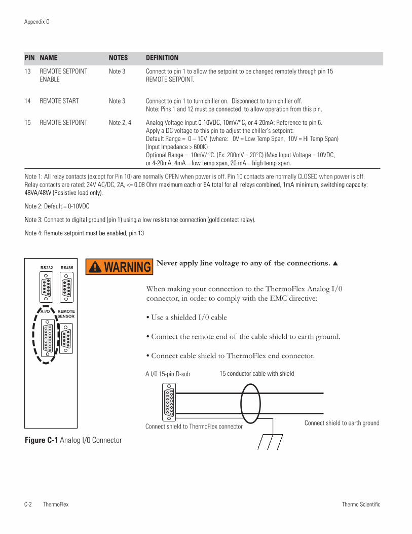
Thermo ScientificC-2 ThermoFlex
Appendix C
Thermo Scientific Thermo Scientific
PIN NAME NOTES DEFINITION
13 REMOTE SETPOINT Note 3 Connect to pin 1 to allow the setpoint to be changed remotely through pin 15 ENABLE REMOTE SETPOINT.
14 REMOTE START Note 3 Connect to pin 1 to turn chiller on. Disconnect to turn chiller off. Note: Pins 1 and 12 must be connected to allow operation from this pin.
15 REMOTE SETPOINT Note 2, 4 Analog Voltage Input 0-10VDC, 10mV/°C, or 4-20mA: Reference to pin 6. Apply a DC voltage to this pin to adjust the chiller's setpoint: Default Range = 0 – 10V (where: 0V = Low Temp Span, 10V = Hi Temp Span) (Input Impedance > 600K) Optional Range = 10mV/ OC. (Ex: 200mV = 20°C) (Max Input Voltage = 10VDC, or 4-20mA, 4mA = low temp span, 20 mA = high temp span.
Note 1: All relay contacts (except for Pin 10) are normally OPEN when power is off. Pin 10 contacts are normally CLOSED when power is off. Relay contacts are rated: 24V AC/DC, 2A, <= 0.08 Ohm maximum each or 5A total for all relays combined, 1mA minimum, switching capacity: 48VA/48W (Resistive load only).
Note 2: Default = 0-10VDC
Note 3: Connect to digital ground (pin 1) using a low resistance connection (gold contact relay).
Note 4: Remote setpoint must be enabled, pin 13
Figure C-1 Analog I/0 Connector
When making your connection to the ThermoFlex Analog I/0 connector, in order to comply with the EMC directive:
• Use a shielded I/0 cable
• Connect the remote end of the cable shield to earth ground.
• Connect cable shield to ThermoFlex end connector.
A I/0 15-pin D-sub 15 conductor cable with shield
Connect shield to earth groundConnect shield to ThermoFlex connector
1 2 3 4 5
6 7 8 91 2 3 4 5
6 7 8 9
1 2 3 4 5
6 7 8 98 7 6 5 4 3 2 1
15 14 13 12 11 10 9
RS232 RS485
A I/O REMOTE SENSOR
8 7 6 5 4 3 2 1
15 14 13 12 11 10 9
Never apply line voltage to any of the connections. WARNING
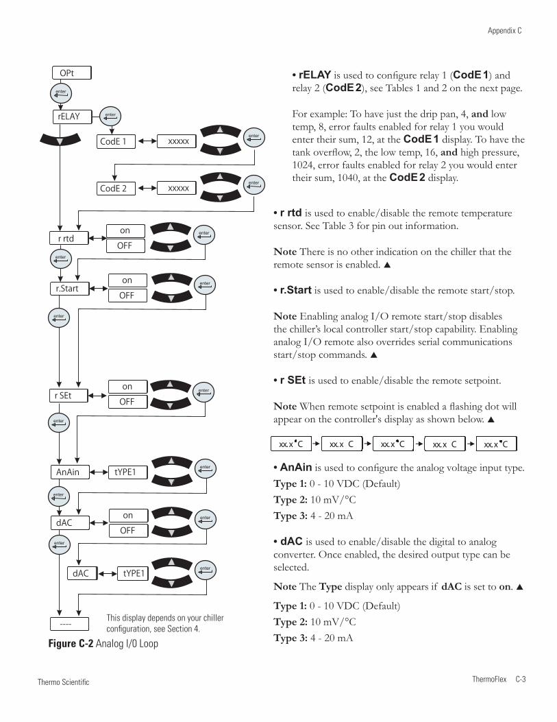
Thermo Scientific
Appendix C
ThermoFlex C-3 Thermo Scientific
• rELAY is used to configure relay 1 (CodE 1) and relay 2 (CodE 2), see Tables 1 and 2 on the next page.
For example: To have just the drip pan, 4, and low temp, 8, error faults enabled for relay 1 you would enter their sum, 12, at the CodE 1 display. To have the tank overflow, 2, the low temp, 16, and high pressure, 1024, error faults enabled for relay 2 you would enter their sum, 1040, at the CodE 2 display.
This display depends on your chillerconfiguration, see Section 4.
Figure C-2 Analog I/0 Loop
xx.x Cxx.x C xx.x C xx.x Cxx.x C xx.x C
• r rtd is used to enable/disable the remote temperature sensor. See Table 3 for pin out information.
Note There is no other indication on the chiller that the remote sensor is enabled.
• r.Start is used to enable/disable the remote start/stop.
Note Enabling analog I/O remote start/stop disables the chiller’s local controller start/stop capability. Enabling analog I/O remote also overrides serial communications start/stop commands.
• r SEt is used to enable/disable the remote setpoint.
Note When remote setpoint is enabled a flashing dot will appear on the controller's display as shown below.
• AnAin is used to configure the analog voltage input type.Type 1: 0 - 10 VDC (Default)Type 2: 10 mV/°CType 3: 4 - 20 mA
• dAC is used to enable/disable the digital to analog converter. Once enabled, the desired output type can be selected.
Note The Type display only appears if dAC is set to on.
Type 1: 0 - 10 VDC (Default)Type 2: 10 mV/°CType 3: 4 - 20 mA
rELAY
CodE 1
CodE 2
enter
enter
xx
xx
xxxxx
xxxxx
enter
enter
r rtd
r.Start
r SEt
AnAin
dAC
dAC
----
xx
xx
xx
xx
xx
xx
xx
xx
xx
xx
OFF
OFF
OFF
OFF
on
on
on
on
tYPE1
tYPE1
enter
enter
enter
enter
enter
enter
enter
enter
enter
enter
enter
OPt
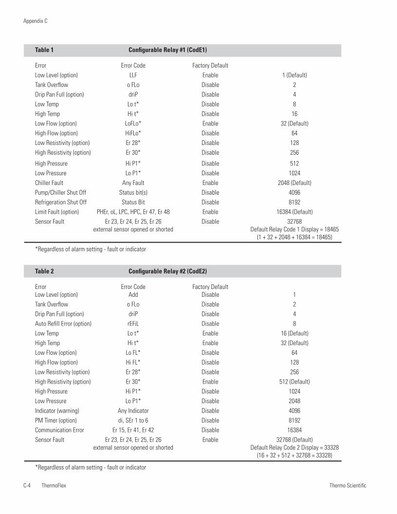
Thermo ScientificC-4 ThermoFlex
Appendix C
Thermo Scientific Thermo Scientific
Table 1 Configurable Relay #1 (CodE1)
Error Error Code Factory Default Low Level (option) LLF Enable 1 (Default)Tank Overflow o FLo Disable 2Drip Pan Full (option) driP Disable 4Low Temp Lo t* Disable 8High Temp Hi t* Disable 16Low Flow (option) LoFLo* Enable 32 (Default)High Flow (option) HiFLo* Disable 64Low Resistivity (option) Er 28* Disable 128High Resistivity (option) Er 30* Disable 256
High Pressure Hi P1* Disable 512Low Pressure Lo P1* Disable 1024Chiller Fault Any Fault Enable 2048 (Default)Pump/Chiller Shut Off Status bit(s) Disable 4096Refrigeration Shut Off Status Bit Disable 8192Limit Fault (option) PHEr, oL, LPC, HPC, Er 47, Er 48 Enable 16384 (Default)Sensor Fault Er 23, Er 24, Er 25, Er 26 Disable 32768 external sensor opened or shorted Default Relay Code 1 Display = 18465 (1 + 32 + 2048 + 16384 = 18465)
*Regardless of alarm setting - fault or indicator
Table 2 Configurable Relay #2 (CodE2)
Error Error Code Factory Default Low Level (option) Add Disable 1Tank Overflow o FLo Disable 2Drip Pan Full (option) driP Disable 4Auto Refill Error (option) rEFiL Disable 8Low Temp Lo t* Enable 16 (Default)High Temp Hi t* Enable 32 (Default)Low Flow (option) Lo FL* Disable 64High Flow (option) Hi FL* Disable 128Low Resistivity (option) Er 28* Disable 256High Resistivity (option) Er 30* Enable 512 (Default)High Pressure Hi P1* Disable 1024Low Pressure Lo P1* Disable 2048Indicator (warning) Any Indicator Disable 4096PM Timer (option) di, SEr 1 to 6 Disable 8192Communication Error Er 15, Er 41, Er 42 Disable 16384Sensor Fault Er 23, Er 24, Er 25, Er 26 Enable 32768 (Default) external sensor opened or shorted Default Relay Code 2 Display = 33328 (16 + 32 + 512 + 32768 = 33328)
*Regardless of alarm setting - fault or indicator
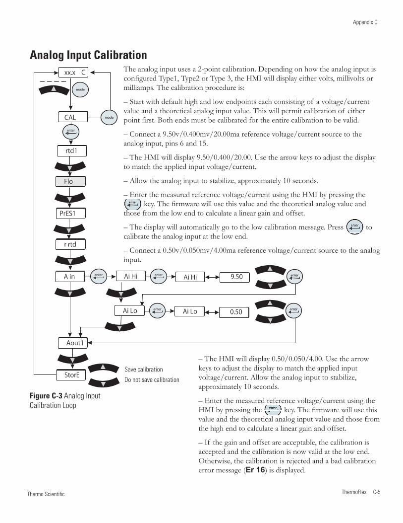
Thermo Scientific
Appendix C
ThermoFlex C-5 Thermo Scientific
Analog Input Calibration
Figure C-3 Analog Input Calibration Loop
xx.x
xx.x
9.50
0.50
Ai HiAi Hi
Ai Lo Ai Lo
xx.x C
mode
rtd1
Flo
CAL
enter
enter enter
enter
enter
enter
mode
r rtd
A in
Aout1
StorE
PrES1
The analog input uses a 2-point calibration. Depending on how the analog input is configured Type1, Type2 or Type 3, the HMI will display either volts, millivolts or milliamps. The calibration procedure is:
– Start with default high and low endpoints each consisting of a voltage/current value and a theoretical analog input value. This will permit calibration of either point first. Both ends must be calibrated for the entire calibration to be valid.
– Connect a 9.50v/0.400mv/20.00ma reference voltage/current source to the analog input, pins 6 and 15.
– The HMI will display 9.50/0.400/20.00. Use the arrow keys to adjust the display to match the applied input voltage/current.
– Allow the analog input to stabilize, approximately 10 seconds.
– Enter the measured reference voltage/current using the HMI by pressing the key. The firmware will use this value and the theoretical analog value and
those from the low end to calculate a linear gain and offset.
– The display will automatically go to the low calibration message. Press to calibrate the analog input at the low end.
– Connect a 0.50v/0.050mv/4.00ma reference voltage/current source to the analog input.
Save calibration
Do not save calibration
– The HMI will display 0.50/0.050/4.00. Use the arrow keys to adjust the display to match the applied input voltage/current. Allow the analog input to stabilize, approximately 10 seconds.
– Enter the measured reference voltage/current using the HMI by pressing the key. The firmware will use this value and the theoretical analog input value and those from the high end to calculate a linear gain and offset.
– If the gain and offset are acceptable, the calibration is accepted and the calibration is now valid at the low end. Otherwise, the calibration is rejected and a bad calibration error message (Er 16) is displayed.
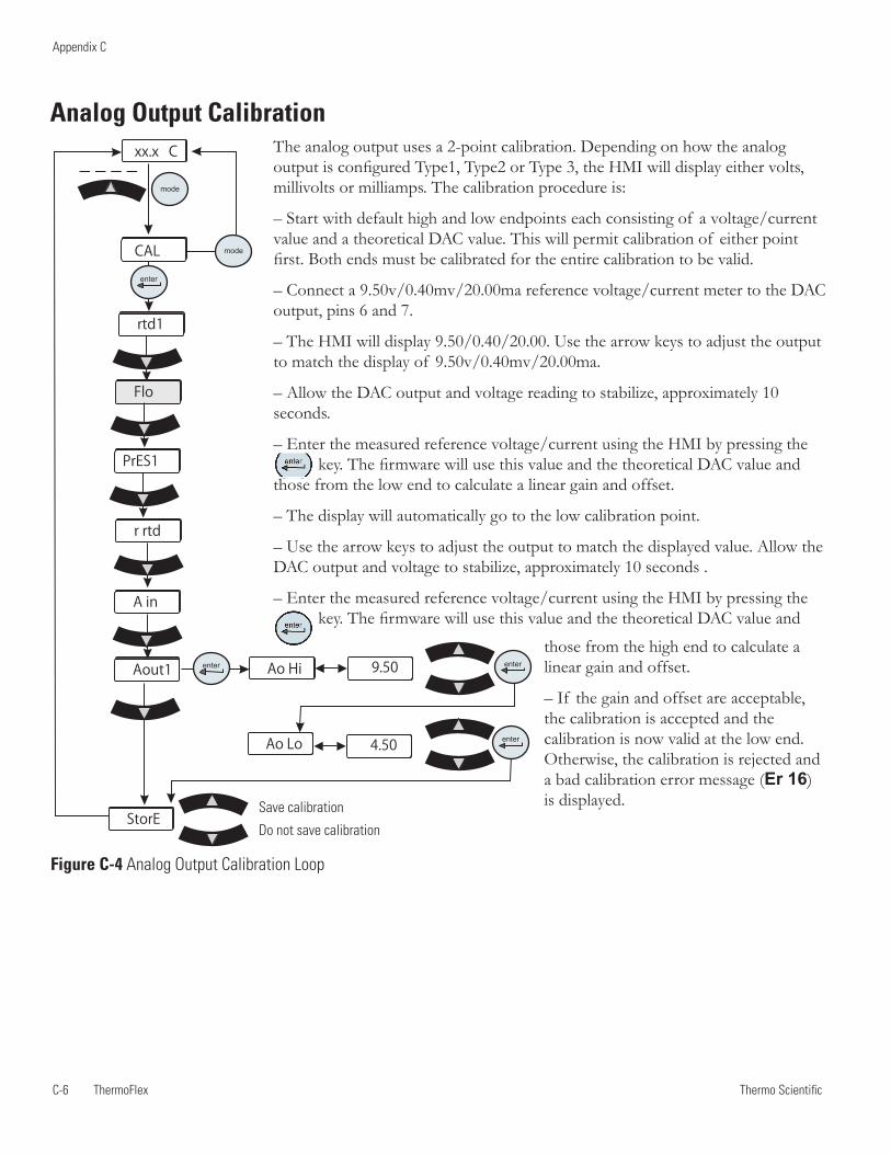
Thermo ScientificC-6 ThermoFlex
Appendix C
Thermo Scientific Thermo Scientific
xx.x
xx.x
9.50
4.50
Ao Hi
Ao Lo
xx.x C
mode
rtd1
Flo
CAL
enter
enter enter
enter
mode
r rtd
A in
Aout1
StorE
PrES1
The analog output uses a 2-point calibration. Depending on how the analog output is configured Type1, Type2 or Type 3, the HMI will display either volts, millivolts or milliamps. The calibration procedure is:
– Start with default high and low endpoints each consisting of a voltage/current value and a theoretical DAC value. This will permit calibration of either point first. Both ends must be calibrated for the entire calibration to be valid.
– Connect a 9.50v/0.40mv/20.00ma reference voltage/current meter to the DAC output, pins 6 and 7.
– The HMI will display 9.50/0.40/20.00. Use the arrow keys to adjust the output to match the display of 9.50v/0.40mv/20.00ma.
– Allow the DAC output and voltage reading to stabilize, approximately 10 seconds.
– Enter the measured reference voltage/current using the HMI by pressing the key. The firmware will use this value and the theoretical DAC value and
those from the low end to calculate a linear gain and offset.
– The display will automatically go to the low calibration point.
– Use the arrow keys to adjust the output to match the displayed value. Allow the DAC output and voltage to stabilize, approximately 10 seconds .
– Enter the measured reference voltage/current using the HMI by pressing the key. The firmware will use this value and the theoretical DAC value and
Analog Output Calibration
those from the high end to calculate a linear gain and offset.
– If the gain and offset are acceptable, the calibration is accepted and the calibration is now valid at the low end. Otherwise, the calibration is rejected and a bad calibration error message (Er 16) is displayed.
Figure C-4 Analog Output Calibration Loop
Save calibration
Do not save calibration
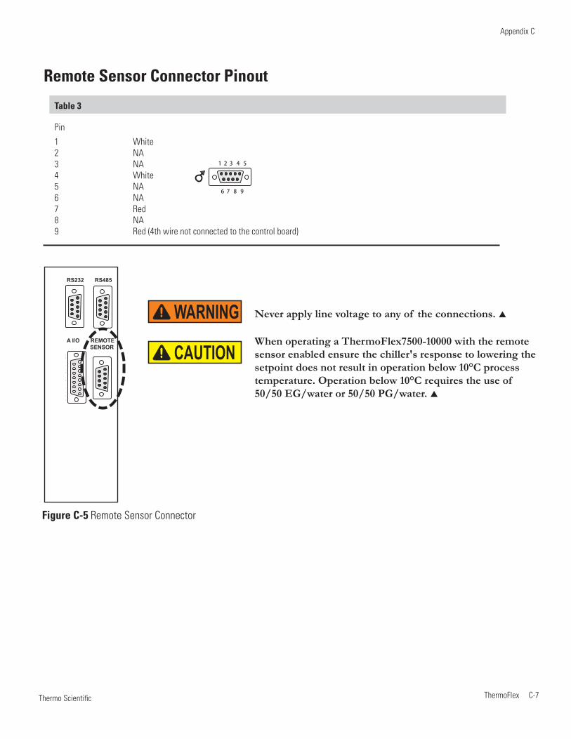
Thermo Scientific
Appendix C
ThermoFlex C-7 Thermo Scientific
Table 3
Pin
1 White 2 NA 3 NA 4 White 5 NA 6 NA 7 Red 8 NA 9 Red (4th wire not connected to the control board)
Figure C-5 Remote Sensor Connector
Remote Sensor Connector Pinout
1 2 3 4 5
6 7 8 9
1 2 3 4 5
6 7 8 91 2 3 4 5
6 7 8 9
1 2 3 4 5
6 7 8 98 7 6 5 4 3 2 1
15 14 13 12 11 10 9
RS232 RS485
A I/O REMOTE SENSOR
Never apply line voltage to any of the connections. WARNINGWhen operating a ThermoFlex7500-10000 with the remote sensor enabled ensure the chiller's response to lowering the setpoint does not result in operation below 10°C process temperature. Operation below 10°C requires the use of 50/50 EG/water or 50/50 PG/water.
CAUTION
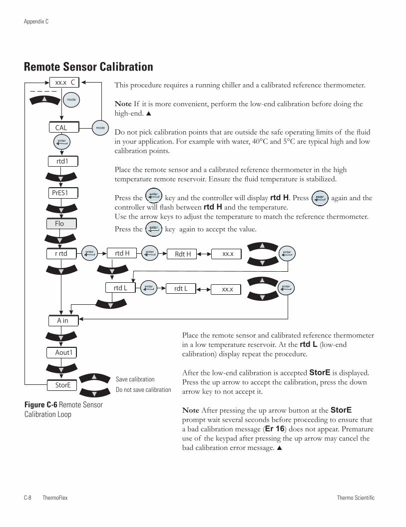
Thermo ScientificC-8 ThermoFlex
Appendix C
Thermo Scientific
xx.x
xx.x
xx.x
xx.x
Rdt Hrtd H
rtd L rdt L
xx.x C
mode
rtd1
Flo
CAL
enter
enter enter
enter
enter
enter
mode
r rtd
A in
Aout1
StorE
PrES1
Remote Sensor Calibration
Figure C-6 Remote Sensor Calibration Loop
This procedure requires a running chiller and a calibrated reference thermometer.
Note If it is more convenient, perform the low-end calibration before doing the high-end.
Do not pick calibration points that are outside the safe operating limits of the fluid in your application. For example with water, 40°C and 5°C are typical high and low calibration points.
Place the remote sensor and a calibrated reference thermometer in the high temperature remote reservoir. Ensure the fluid temperature is stabilized.
Press the key and the controller will display rtd H. Press again and the controller will flash between rtd H and the temperature. Use the arrow keys to adjust the temperature to match the reference thermometer. Press the key again to accept the value.
Save calibration
Do not save calibration
Place the remote sensor and calibrated reference thermometer in a low temperature reservoir. At the rtd L (low-end calibration) display repeat the procedure.
After the low-end calibration is accepted StorE is displayed. Press the up arrow to accept the calibration, press the down arrow key to not accept it.
Note After pressing the up arrow button at the StorE prompt wait several seconds before proceeding to ensure that a bad calibration message (Er 16) does not appear. Premature use of the keypad after pressing the up arrow may cancel the bad calibration error message.
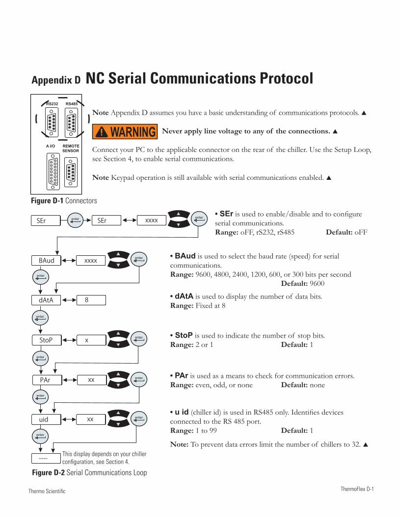
ThermoFlex D-1 Thermo Scientific
Appendix D NC Serial Communications Protocol
Note Appendix D assumes you have a basic understanding of communications protocols.
Never apply line voltage to any of the connections.
Connect your PC to the applicable connector on the rear of the chiller. Use the Setup Loop, see Section 4, to enable serial communications.
Note Keypad operation is still available with serial communications enabled.
• SEr is used to enable/disable and to configure serial communications.Range: oFF, rS232, rS485 Default: oFF
This display depends on your chillerconfiguration, see Section 4.
Figure D-1 Connectors
Figure D-2 Serial Communications Loop
BAud
StoP
dAtA
PAr
uid
----
SEr SEr
enter
enter
enter
enter
enter
enter
xx
xx
xx
xx
xx
xx
xxxx
8
xxxx
x
xx
xx
enter
enter
enter
enter
enter
1 2 3 4 5
6 7 8 91 2 3 4 5
6 7 8 9
1 2 3 4 5
6 7 8 98 7 6 5 4 3 2 1
15 14 13 12 11 10 9
RS232 RS485
A I/O REMOTE SENSOR
• BAud is used to select the baud rate (speed) for serial communications.Range: 9600, 4800, 2400, 1200, 600, or 300 bits per second Default: 9600
• dAtA is used to display the number of data bits.Range: Fixed at 8
• StoP is used to indicate the number of stop bits.Range: 2 or 1 Default: 1
• PAr is used as a means to check for communication errors.Range: even, odd, or none Default: none
• u id (chiller id) is used in RS485 only. Identifies devices connected to the RS 485 port.Range: 1 to 99 Default: 1
Note: To prevent data errors limit the number of chillers to 32.
WARNING
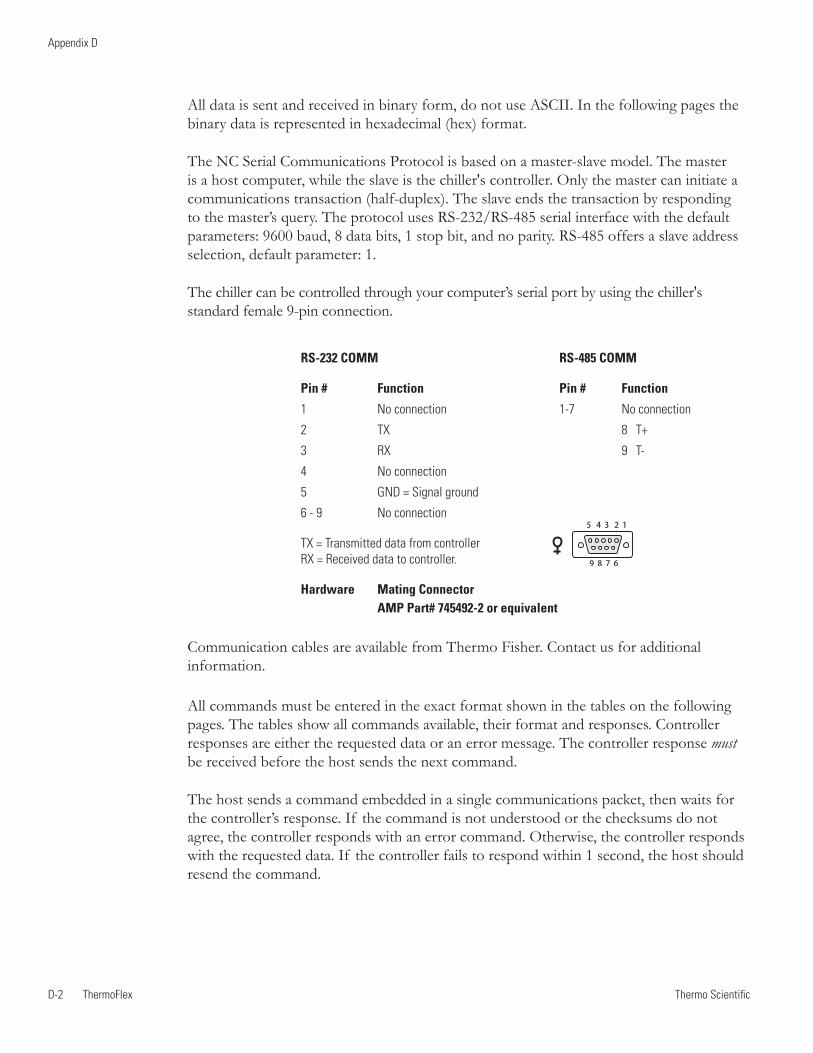
Thermo ScientificD-2 ThermoFlex
Appendix D
Thermo Scientific Thermo Scientific
RS-232 COMM RS-485 COMM
Pin # Function Pin # Function
1 No connection 1-7 No connection
2 TX 8 T+
3 RX 9 T-
4 No connection
5 GND = Signal ground
6 - 9 No connection
TX = Transmitted data from controller RX = Received data to controller.
Hardware Mating Connector AMP Part# 745492-2 or equivalent
All data is sent and received in binary form, do not use ASCII. In the following pages the binary data is represented in hexadecimal (hex) format.
The NC Serial Communications Protocol is based on a master-slave model. The master is a host computer, while the slave is the chiller's controller. Only the master can initiate a communications transaction (half-duplex). The slave ends the transaction by responding to the master’s query. The protocol uses RS-232/RS-485 serial interface with the default parameters: 9600 baud, 8 data bits, 1 stop bit, and no parity. RS-485 offers a slave address selection, default parameter: 1.
The chiller can be controlled through your computer’s serial port by using the chiller's standard female 9-pin connection.
Communication cables are available from Thermo Fisher. Contact us for additional information.
5 4 3 2 1
9 8 7 6
All commands must be entered in the exact format shown in the tables on the following pages. The tables show all commands available, their format and responses. Controller responses are either the requested data or an error message. The controller response must be received before the host sends the next command.
The host sends a command embedded in a single communications packet, then waits for the controller’s response. If the command is not understood or the checksums do not agree, the controller responds with an error command. Otherwise, the controller responds with the requested data. If the controller fails to respond within 1 second, the host should resend the command.
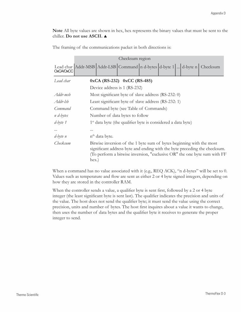
Thermo Scientific
Appendix D
ThermoFlex D-3 Thermo Scientific
Note All byte values are shown in hex, hex represents the binary values that must be sent to the chiller. Do not use ASCII.
The framing of the communications packet in both directions is:
Checksum region
Lead char Addr-MSB Addr-LSB Command n d-bytes d-byte 1 ... d-byte n Checksum
Lead char 0xCA (RS-232) 0xCC (RS-485) Device address is 1 (RS-232)Addr-msb Most significant byte of slave address (RS-232: 0)Addr-lsb Least significant byte of slave address (RS-232: 1)Command Command byte (see Table of Commands)n d-bytes Number of data bytes to follow d-byte 1 1st data byte (the qualifier byte is considered a data byte)... ...d-byte n nth data byte.Checksum Bitwise inversion of the 1 byte sum of bytes beginning with the most significant address byte and ending with the byte preceding the checksum. (To perform a bitwise inversion, "exclusive OR" the one byte sum with FF hex.)
When a command has no value associated with it (e.g., REQ ACK), “n d-bytes” will be set to 0. Values such as temperature and flow are sent as either 2 or 4 byte signed integers, depending on how they are stored in the controller RAM.
When the controller sends a value, a qualifier byte is sent first, followed by a 2 or 4 byte integer (the least significant byte is sent last). The qualifier indicates the precision and units of the value. The host does not send the qualifier byte; it must send the value using the correct precision, units and number of bytes. The host first inquires about a value it wants to change, then uses the number of data bytes and the qualifier byte it receives to generate the proper integer to send.
OxCA/OxCC
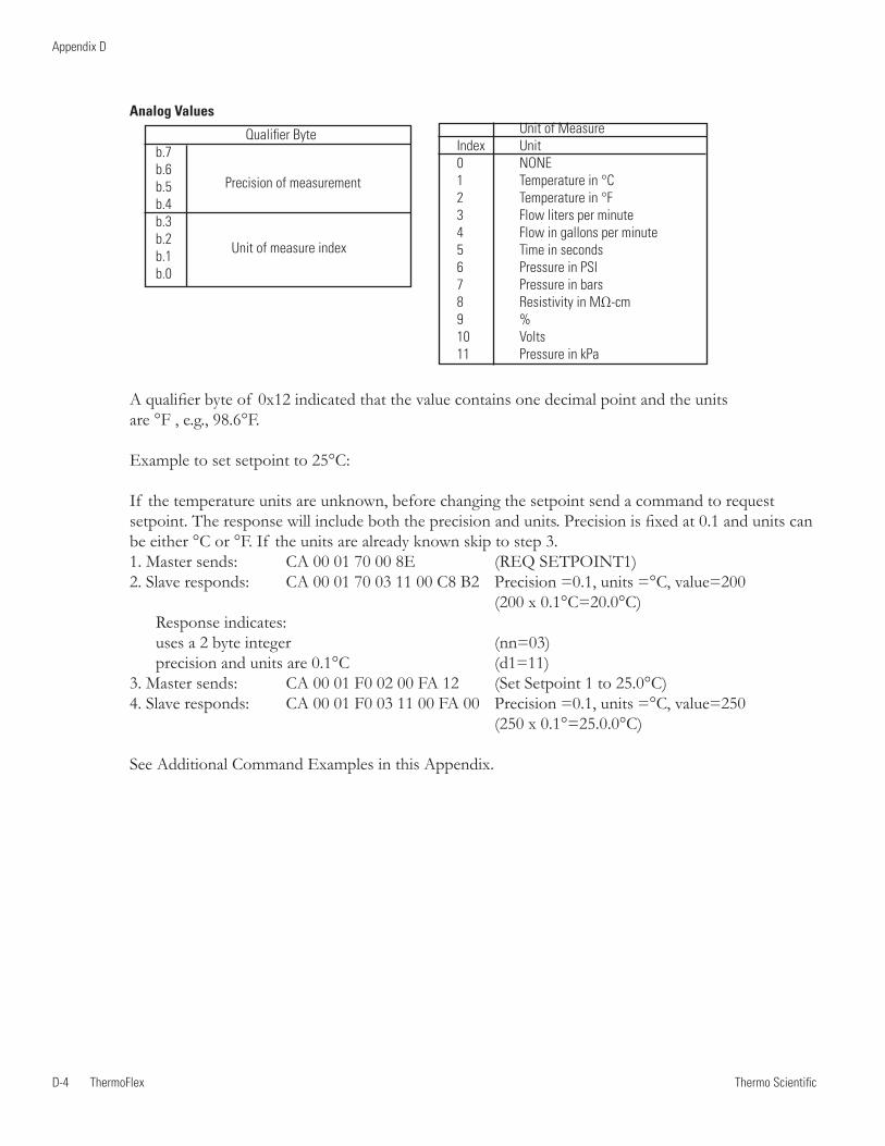
Thermo ScientificD-4 ThermoFlex
Appendix D
Thermo Scientific Thermo Scientific
Analog Values
Qualifier Byteb.7 b.6 b.5 b.4 b.3 b.2 b.1 b.0
A qualifier byte of 0x12 indicated that the value contains one decimal point and the units are °F , e.g., 98.6°F.
Example to set setpoint to 25°C:
If the temperature units are unknown, before changing the setpoint send a command to request setpoint. The response will include both the precision and units. Precision is fixed at 0.1 and units can be either °C or °F. If the units are already known skip to step 3.1. Master sends: CA 00 01 70 00 8E (REQ SETPOINT1)2. Slave responds: CA 00 01 70 03 11 00 C8 B2 Precision =0.1, units =°C, value=200 (200 x 0.1°C=20.0°C) Response indicates: uses a 2 byte integer (nn=03) precision and units are 0.1°C (d1=11)3. Master sends: CA 00 01 F0 02 00 FA 12 (Set Setpoint 1 to 25.0°C)4. Slave responds: CA 00 01 F0 03 11 00 FA 00 Precision =0.1, units =°C, value=250 (250 x 0.1°=25.0.0°C)
See Additional Command Examples in this Appendix.
Unit of MeasureIndex Unit0 NONE1 Temperature in °C2 Temperature in °F3 Flow liters per minute4 Flow in gallons per minute5 Time in seconds6 Pressure in PSI7 Pressure in bars8 Resistivity in MΩ-cm 9 % 10 Volts 11 Pressure in kPa
Precision of measurement
Unit of measure index
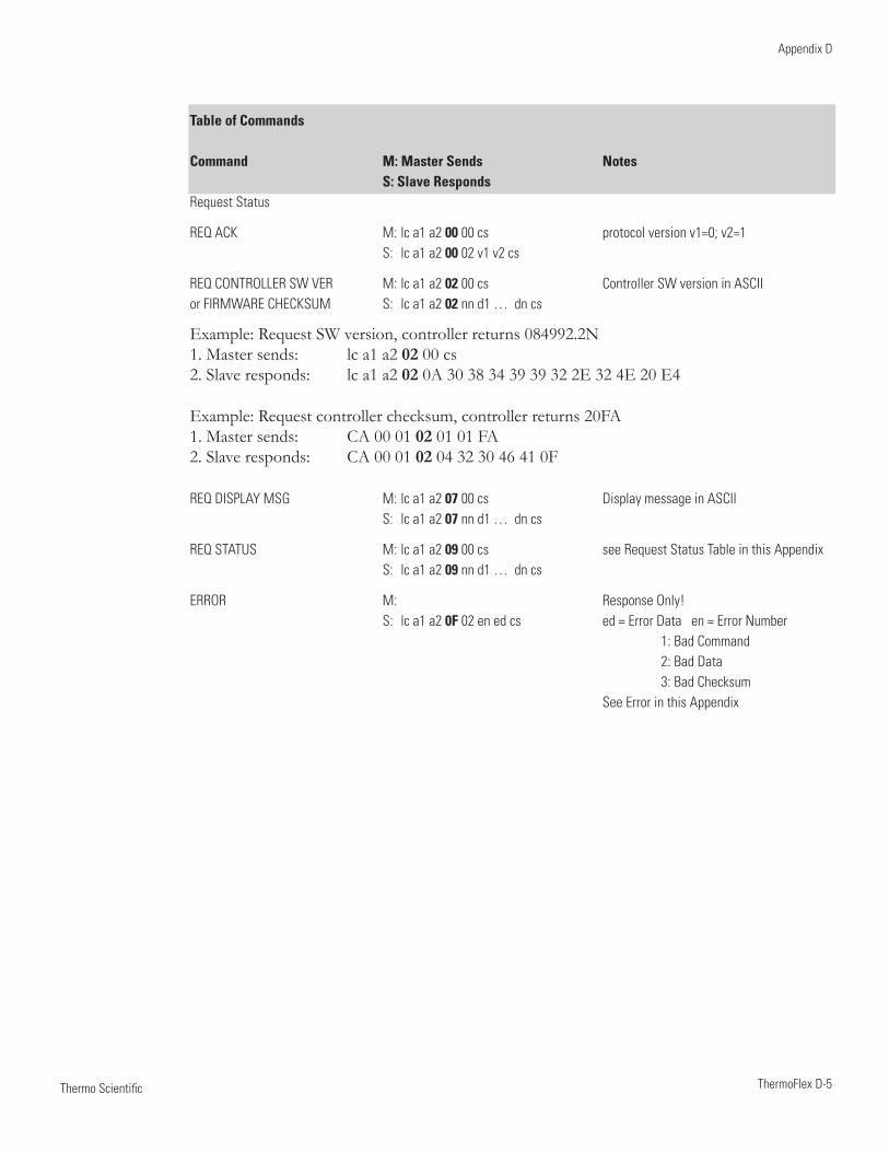
Thermo Scientific
Appendix D
ThermoFlex D-5 Thermo Scientific
Table of Commands
Command M: Master Sends Notes S: Slave RespondsRequest Status
REQ ACK M: lc a1 a2 00 00 cs protocol version v1=0; v2=1 S: lc a1 a2 00 02 v1 v2 cs
REQ CONTROLLER SW VER M: lc a1 a2 02 00 cs Controller SW version in ASCII or FIRMWARE CHECKSUM S: lc a1 a2 02 nn d1 … dn cs
Example: Request SW version, controller returns 084992.2N1. Master sends: lc a1 a2 02 00 cs 2. Slave responds: lc a1 a2 02 0A 30 38 34 39 39 32 2E 32 4E 20 E4
Example: Request controller checksum, controller returns 20FA1. Master sends: CA 00 01 02 01 01 FA 2. Slave responds: CA 00 01 02 04 32 30 46 41 0F
REQ DISPLAY MSG M: lc a1 a2 07 00 cs Display message in ASCII S: lc a1 a2 07 nn d1 … dn cs
REQ STATUS M: lc a1 a2 09 00 cs see Request Status Table in this Appendix S: lc a1 a2 09 nn d1 … dn cs
ERROR M: Response Only! S: lc a1 a2 0F 02 en ed cs ed = Error Data en = Error Number 1: Bad Command 2: Bad Data 3: Bad Checksum See Error in this Appendix
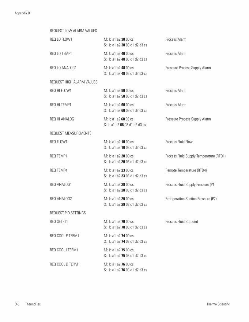
Thermo ScientificD-6 ThermoFlex
Appendix D
Thermo Scientific Thermo Scientific
REQUEST LOW ALARM VALUES
REQ LO FLOW1 M: lc a1 a2 30 00 cs Process Alarm S: lc a1 a2 30 03 d1 d2 d3 cs
REQ LO TEMP1 M: lc a1 a2 40 00 cs Process Alarm S: lc a1 a2 40 03 d1 d2 d3 cs
REQ LO ANALOG1 M: lc a1 a2 48 00 cs Pressure Process Supply Alarm S: lc a1 a2 48 03 d1 d2 d3 cs
REQUEST HIGH ALARM VALUES
REQ HI FLOW1 M: lc a1 a2 50 00 cs Process Alarm S: lc a1 a2 50 03 d1 d2 d3 cs
REQ HI TEMP1 M: lc a1 a2 60 00 cs Process Alarm S: lc a1 a2 60 03 d1 d2 d3 cs
REQ HI ANALOG1 M: lc a1 a2 68 00 cs Pressure Process Supply Alarm S: lc a1 a2 68 03 d1 d2 d3 cs
REQUEST MEASUREMENTS
REQ FLOW1 M: lc a1 a2 10 00 cs Process Fluid Flow S: lc a1 a2 10 03 d1 d2 d3 cs
REQ TEMP1 M: lc a1 a2 20 00 cs Process Fluid Supply Temperature (RTD1) S: lc a1 a2 20 03 d1 d2 d3 cs
REQ TEMP4 M: lc a1 a2 23 00 cs Remote Temperature (RTD4) S: lc a1 a2 23 03 d1 d2 d3 cs
REQ ANALOG1 M: lc a1 a2 28 00 cs Process Fluid Supply Pressure (P1) S: lc a1 a2 28 03 d1 d2 d3 cs
REQ ANALOG2 M: lc a1 a2 29 00 cs Refrigeration Suction Pressure (P2) S: lc a1 a2 29 03 d1 d2 d3 cs
REQUEST PID SETTINGS
REQ SETPT1 M: lc a1 a2 70 00 cs Process Fluid Setpoint S: lc a1 a2 70 03 d1 d2 d3 cs
REQ COOL P TERM1 M: lc a1 a2 74 00 cs S: lc a1 a2 74 03 d1 d2 d3 cs
REQ COOL I TERM1 M: lc a1 a2 75 00 cs S: lc a1 a2 75 03 d1 d2 d3 cs
REQ COOL D TERM1 M: lc a1 a2 76 00 cs S: lc a1 a2 76 03 d1 d2 d3 cs
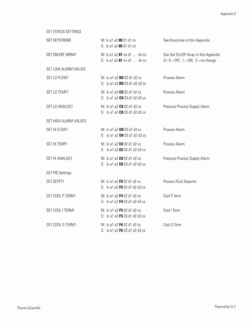
Thermo Scientific
Appendix D
ThermoFlex D-7 Thermo Scientific
SET STATUS SETTINGS
SET KEYSTROKE M: lc a1 a2 80 01 d1 cs See Keystroke in this Appendix S: lc a1 a2 80 01 d1 cs
SET ON/OFF ARRAY M: lc a1 a2 81 nn d1 … dn cs See Set On/Off Array in this Appendix S: lc a1 a2 81 nn d1 … dn cs d1: 0 = OFF, 1 = ON, 2 = no change
SET LOW ALARM VALUES
SET LO FLOW1 M: lc a1 a2 B0 02 d1 d2 cs Process Alarm S: lc a1 a2 B0 03 d1 d2 d3 cs
SET LO TEMP1 M: lc a1 a2 C0 02 d1 d2 cs Process Alarm S: lc a1 a2 C0 03 d1 d2 d3 cs
SET LO ANALOG1 M: lc a1 a2 C8 02 d1 d2 cs Pressure Process Supply Alarm S: lc a1 a2 C8 03 d1 d2 d3 cs
SET HIGH ALARM VALUES
SET HI FLOW1 M: lc a1 a2 D0 02 d1 d2 cs Process Alarm S: lc a1 a2 D0 03 d1 d2 d3 cs
SET HI TEMP1 M: lc a1 a2 E0 02 d1 d2 cs Process Alarm S: lc a1 a2 E0 03 d1 d2 d3 cs
SET HI ANALOG1 M: lc a1 a2 E8 02 d1 d2 cs Pressure Process Supply Alarm S: lc a1 a2 E8 03 d1 d2 d3 cs
SET PID Settings
SET SETPT1 M: lc a1 a2 F0 02 d1 d2 cs Process Fluid Setpoint S: lc a1 a2 F0 03 d1 d2 d3 cs
SET COOL P TERM1 M: lc a1 a2 F4 02 d1 d2 cs Cool P Term S: lc a1 a2 F4 03 d1 d2 d3 cs
SET COOL I TERM1 M: lc a1 a2 F5 02 d1 d2 cs Cool I Term S: lc a1 a2 F5 03 d1 d2 d3 cs
SET COOL D TERM1 M: lc a1 a2 F6 02 d1 d2 cs Cool D Term S: lc a1 a2 F6 03 d1 d2 d3 cs
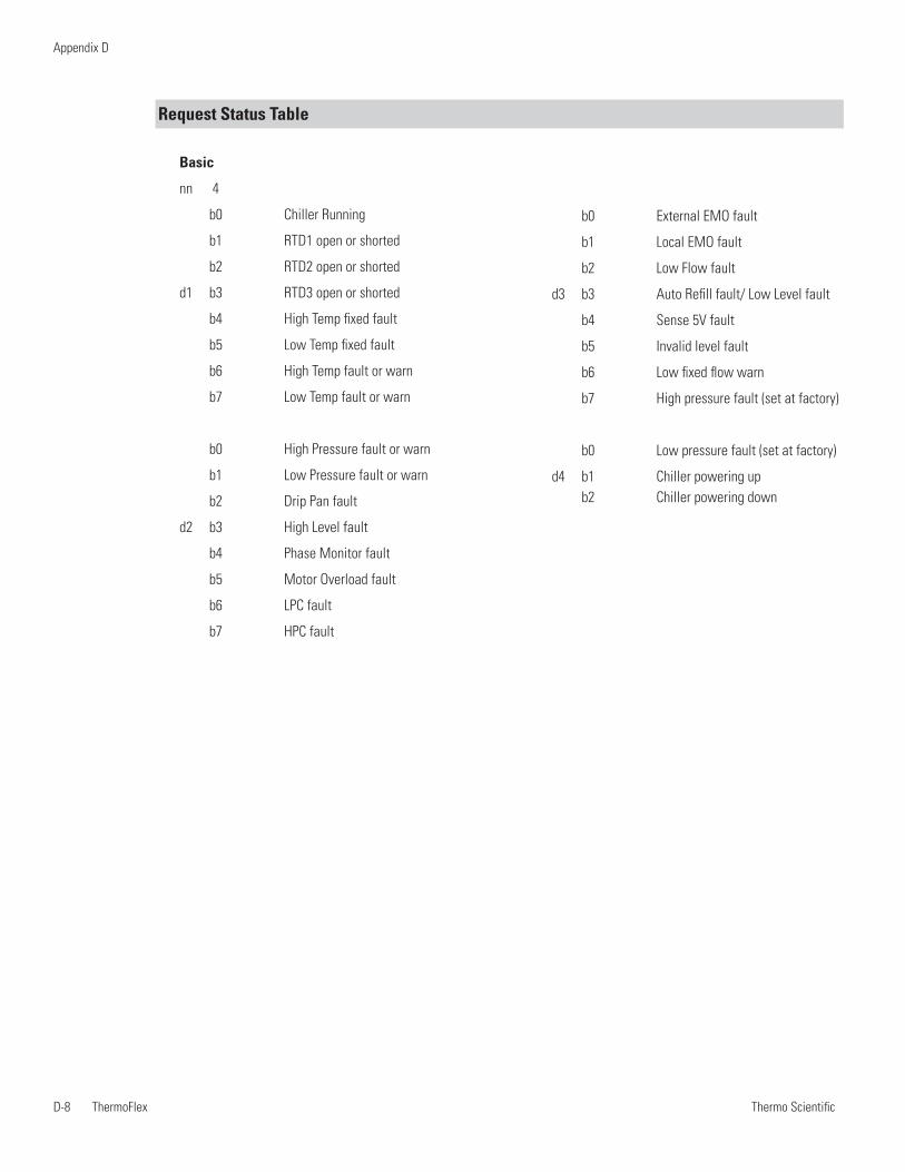
Thermo ScientificD-8 ThermoFlex
Appendix D
Thermo Scientific Thermo Scientific
Request Status Table
Basic
nn 4
b0 Chiller Running
b1 RTD1 open or shorted
b2 RTD2 open or shorted
d1 b3 RTD3 open or shorted
b4 High Temp fixed fault
b5 Low Temp fixed fault
b6 High Temp fault or warn
b7 Low Temp fault or warn
b0 High Pressure fault or warn
b1 Low Pressure fault or warn
b2 Drip Pan fault
d2 b3 High Level fault
b4 Phase Monitor fault
b5 Motor Overload fault
b6 LPC fault
b7 HPC fault
b0 External EMO fault
b1 Local EMO fault
b2 Low Flow fault
d3 b3 Auto Refill fault/ Low Level fault
b4 Sense 5V fault
b5 Invalid level fault
b6 Low fixed flow warn
b7 High pressure fault (set at factory)
b0 Low pressure fault (set at factory)
d4 b1 Chiller powering up b2 Chiller powering down
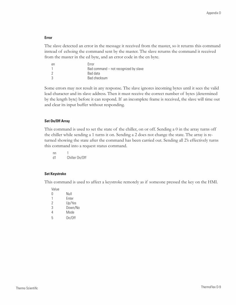
Thermo Scientific
Appendix D
ThermoFlex D-9 Thermo Scientific
Error
The slave detected an error in the message it received from the master, so it returns this command instead of echoing the command sent by the master. The slave returns the command it received from the master in the ed byte, and an error code in the en byte.
en Error1 Bad command – not recognized by slave2 Bad data3 Bad checksum
Some errors may not result in any response. The slave ignores incoming bytes until it sees the valid lead character and its slave address. Then it must receive the correct number of bytes (determined by the length byte) before it can respond. If an incomplete frame is received, the slave will time out and clear its input buffer without responding.
Set On/Off Array
This command is used to set the state of the chiller, on or off. Sending a 0 in the array turns off the chiller while sending a 1 turns it on. Sending a 2 does not change the state. The array is re-turned showing the state after the command has been carried out. Sending all 2’s effectively turns this command into a request status command.
nn 1d1 Chiller On/Off
Set Keystroke
This command is used to affect a keystroke remotely as if someone pressed the key on the HMI. Value 0 Null1 Enter2 Up/Yes3 Down/No4 Mode5 On/Off
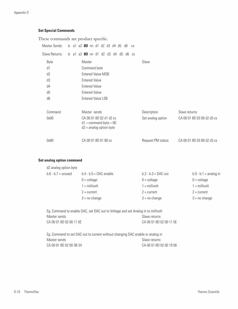
Thermo ScientificD-10 ThermoFlex
Appendix D
Thermo Scientific
Set Special Commands
These commands are product specific.Master Sends: lc a1 a2 8D nn d1 d2 d3 d4 d5 d6 cs
Slave Returns: lc a1 a2 8D nn d1 d2 d3 d4 d5 d6 cs
Byte Master Slave
d1 Command byte
d2 Entered Value MSB
d3 Entered Value
d4 Entered Value
d5 Entered Value
d6 Entered Value LSB
Command Master sends Description Slave returns
0x00 CA 00 01 8D 02 d1 d2 cs Set analog option CA 00 01 8D 03 00 d2 d3 cs d1 = command byte = 00 d2 = analog option byte
0x80 CA 00 01 8D 01 80 cs Request PM status CA 00 01 8D 03 80 d2 d3 cs
Set analog option command
d2 analog option byte
b.6 - b.7 = unused b.4 - b.5 = DAC enable b.2 - b.3 = DAC out b.0 - b.1 = analog in
0 = voltage 0 = voltage 0 = voltage
1 = millivolt 1 = millivolt 1 = millivolt
2 = current 2 = current 2 = current
3 = no change 3 = no change 3 = no change
Eg. Command to enable DAC, set DAC out to Voltage and set Analog in to millivolt Master sends Slave returns CA 00 01 8D 02 00 11 5E CA 00 01 8D 02 00 11 5E
Eg. Command to set DAC out to current without changing DAC enable or analog in Master sends Slave returns CA 00 01 8D 02 00 3B 34 CA 00 01 8D 02 00 19 56
Laboratory Equipment Div.
25 Nimble Hill Road
Newington, NH 03801
D of C 094026.1 Form 094233-P DWG # 094026 REV 14 Sep 11
DECLARATION OF CONFORMITY
Manufacturer: Thermo Fisher Scientific
Address: 25 Nimble Hill Road
Newington, NH 03801 USA
Products: Refrigerated chillers and heat exchangers. Year of inception 2013
We declare that the following products conform to the Directives and Standards listed below:
Unit has a 16 digit part number consisting of UU TVPC XXXXXXXX defined as follows:
UU = Unit type can be:
10 = TF 900 11 = TF 1,400 12 = TF 2,500 13 = TF 3,500 14 = TF 5,000
15 = TF 7,500 16 = TF 10,000 17 = TF 15,000 18 = TF 20,000 19 = TF 24,000
T = Type of unit cooling and Temperature Range can be 1-4 inclusive, where:
1 = Air Cooled Standard Temp ( 5-40°C ) 2 = Air Cooled Hi Temp ( 5-90°C )
3 = Water Cooled Standard Temp ( 5-40°C ) 4 = Water Cooled Hi Temp ( 5-90°C )
V = Unit voltage rating:
1 = 115V, 60Hz 1Ph 17 = 200/208/230V, 60Hz 3Ph 17 = 208/230V, 60Hz 3Ph
100V, 50Hz 1Ph 200V, 50Hz 3Ph
2 = 100/115V, 60Hz 1Ph 18 = 400V, 50Hz 3Ph 18 = 400V, 50Hz 3Ph
100/115V, 50Hz 1Ph 20 = 200/208/230V, 60Hz 3Ph
3 = 208/230V, 60Hz 1Ph 200-230V, 50Hz 3Ph
200V, 50Hz 1Ph 21 = 460V, 60Hz 3Ph 21 = 460V, 60Hz 3Ph
4 = 230V, 50Hz 1Ph 400V, 50Hz 3Ph 400V, 50Hz 3Ph
7 = 200/208/230V, 60Hz 1Ph
200/230V, 50Hz 1Ph
P = Pump type, can be 0 through 9 inclusive or B, C or F.
C = Unit controller type, can be any digit 1-6, inclusive.
X = Any digit 0-9 inclusive, used as sequential numbering only.
Equipment Class: Measurement, control and laboratory
Directives and Standards:
2004/108/EC – Electromagnetic Compatibility ( EMCD ):
EN 61326-1: 2006 – Electrical equipment for measurement, control, and laboratory use – EMC requirements, EMC Class A
2006/95/EC – Low Voltage Directive ( LVD ):
EN/IEC 61010-1: 2010 – Safety Requirements For Electrical Equipment For Measurement, Control, And Laboratory Use: General Requirements.
EN 61010-1: 2001 – Safety Requirements For Electrical Equipment For Measurement, Control, And Laboratory Use: General Requirements.
EN 61010-2-010: 2003 – Safety Requirements For Electrical Equipment For Measurement, Control, And Laboratory Use – Part 2-010: Particular Requirements For Laboratory Equipment For The Heating Of Materials.
Additional EMC Evaluations with Certificates:
EN 61000-3-2: 2006 Harmonics
EN 61000-3-3: 2008 Flicker
Manufacturer’s Authorized Representative: Date:
__________________________ 20 Sept. 2013
Robin Wiley Compliance Engineering

WARRANTY
Thermo Fisher Scientific warrants for 24 months (excluding MD 1/MD 2 Magnetic Drive and P 1/P 2 Positive Displacement pumps which are warranted for 12 months) from date of shipment the Thermo Scientific ThermoFlex chiller according to the following terms.
Any part of the chiller manufactured or supplied by Thermo Fisher Scientific and found in the reasonable judgment of Thermo Fisher to be defective in material or workmanship will be repaired at an authorized Thermo Fisher Repair Depot without charge for parts or labor. The chiller, including any defective part must be returned to an authorized Thermo Fisher Repair Depot within the warranty period. The expense of returning the chiller to the authorized Thermo Fisher Repair Depot for warranty service will be paid for by the buyer. Our responsibility in respect to warranty claims is limited to performing the required repairs or replacements, and no claim of breach of warranty shall be cause for cancellation or recision of the contract of sales of any chiller. With respect to chillers that qualify for field service repairs, Thermo Fisher Scientific’s responsibility is limited to the component parts necessary for the repair and the labor that is required on site to perform the repair. Any travel labor or mileage charges are the financial responsibility of the buyer.
The buyer shall be responsible for any evaluation or warranty service call (including labor charges) if no defects are found with the Thermo Scientific product.
This warranty does not cover any chiller that has been subject to misuse, neglect, or accident. This warranty does not apply to any damage to the chiller that is the result of improper installation or maintenance, or to any chiller that has been operated or maintained in any way contrary to the operating or maintenance instructions specified in this Instruction and Operation Manual. This warranty does not cover any chiller that has been altered or modified so as to change its intended use.
In addition, this warranty does not extend to repairs made by the use of parts, accessories, or fluids which are either incompatible with the chiller or adversely affect its operation, performance, or durability.
Thermo Fisher Scientific reserves the right to change or improve the design of any chiller without assuming any obligation to modify any chiller previously manufactured.
THE FOREGOING EXPRESS WARRANTY IS IN LIEU OF ALL OTHER WARRANTIES, EXPRESSED OR IMPLIED, INCLUDING BUT NOT LIMITED TO WARRANTIES OR MERCHANTABILITY AND FITNESS FOR A PARTICULAR PURPOSE.
OUR OBLIGATION UNDER THIS WARRANTY IS STRICTLY AND EXCLUSIVELY LIMITED TO THE REPAIR OR REPLACEMENT OF DEFECTIVE COMPONENT PARTS AND Thermo Fisher Scientific DOES NOT ASSUME OR AUTHORIZE ANYONE TO ASSUME FOR IT ANY OTHER OBLIGATION.
Thermo Fisher Scientific ASSUMES NO RESPONSIBILITY FOR INCIDENTAL, CONSEQUENTIAL, OR OTHER DAMAGES INCLUDING, BUT NOT LIMITED TO LOSS OR DAMAGE TO PROPERTY, LOSS OF PROFITS OR REVENUE, LOSS OF THE CHILLER, LOSS OF TIME, OR INCONVENIENCE.
This warranty applies to chillers sold by Thermo Fisher Scientific. (Refer to the warranty for chillers sold by the affiliated marketing company of Thermo Fisher Scientific for any additional terms.) This warranty and all matters arising pursuant to it shall be governed by the law of the State of New Hampshire, United States. All legal actions brought in relation hereto shall be filed in the appropriate state or federal courts in New Hampshire, unless waived by Thermo Fisher Scientific.


Thermo Fisher Scientific81 Wyman StreetP.O. Box 9046Waltham, Massachusetts 02454-9046United States
www.thermofisher.com


![RECIRCULATING LOOP CHILLERS - | Filtrine Manufacturing [PCP-1000S].pdf · RECIRCULATING LOOP CHILLERS MODELS ... • POC - Open Loop Chillers - pump liquid from an open tank or sump,](https://img.dokumen.tips/doc/110x75/5ae70df17f8b9a08778dd23b/recirculating-loop-chillers-filtrine-manufacturing-pcp-1000spdfrecirculating.jpg)