Embed Size (px)
Citation preview
Reciprocating metering pump with spring return
USE
AN
D M
AIN
TEN
AN
CE
MA
NU
AL
METERING PUMP WITH SPRING RETURN SR Series mod. A PLUNGER mod. D MECHANICAL DIAPHRAGM mod. B HYDRAULIC DIAPHRAGM mod. BR HYDRAULIC DIAPHRAGM
WITH RELIEF VALVE mod. SD SANDWICH HYDRAULIC
DIAPHRAGM WITH RELIEF VALVE
ATTENTION: Industrial machinery for professional use. These instructions are for qualified personnel
Translation of the original instructions
EN SD
BR
B
D
A
2014 EDITION

DOSEURO®
TABLE OF CONTENTS Ref. Title Page 1 PREFACE 4
1.1 General prescriptions 4 1.2 Technical assistance 4 1.3 Electric motors 4 1.4 Liability 4 1.1 CE Declaration of conformity 6
2 TERMINOLOGY DEFINITIONS AND MEANINGS OF USED SYMBOLS 7
2.1 Symbols 7 2.2 Minimum qualification of personnel 7
3 SAFETY STANDARDS DURING USE 8
3.1 Clothing 9
4 USING THE METERING PUMPS 9
4.1 Destination of use 9 4.2 Intended and non-intended use of the pump 9 4.3 Conditions of use 9 4.4 Pump description 9 4.5 Machine description 10 4.6 Identification plate 11
5 TRANSPORT 11 5.1 Lifting and handling 11 5.2 Material storage 12 5.3 Handling for installation 12
6 PUMP INSTALLATION 12
6.1 Optimum conditions for installation 12 6.2 Pump location 12
7 PUMP CONNECTION TO PLANT PIPING 12 7.1 Removal of guards 12 7.2 Connection of suction piping 13 7.3 Connection of delivery piping 15
8 DESCRIPTION OF STANDARD PLANT ACCESSORIES 15
8.1 Pulsation dampener 16 8.2 Pressure gauge 16 8.3 Safety relief valve 16 8.4 Sampling or draining 16 8.5 Filter 16 8.6 Flowmeter 16 8.7 Back pressure valve 17 8.8 Shut-off valve in delivery piping 17
9 LUBRICATION 17
10 ELECTRICAL CONNECTION 18 10.1 Motor connection 18
11 PUMP ADJUSTMENT 19 11.1 Stroke variation with manual system 19 11.2 Stroke variation with servocontrol 19
XMPE0PCG125NST014 1st Edition - 2014 2/28

DOSEURO®
12 OPTIONAL ACCESSORIES 19 12.1 Control with inductive proximity sensor 19
13 PROCEDURE PRIOR TO START-UP 20 13.1 Commissioning 20 13.2 Inconveniences upon commissioning 20
14 MAINTENANCE 21
14.1 List of spare parts 21
15 PREVENTIVE MAINTENANCE 22
15.1 Noisy mechanics with vibrations 22 15.2 Electric motor 22 15.3 Checking of flexible coupling 22 15.4 Verification of pump flow rate 22 15.5 Pressure 23
16 ROUTINE MAINTENANCE 23
16.1 Maintenance procedures 23 16.2 Residual risks 24
17 PUMP DECOMMISSIONING 25
17.1 Disposal of components and harmful substances 23
18 REPAIR MAINTENANCE 25
18.1 Practical advice for hardening and tempering 26
19 INFORMATION FOR USERS 27
XMPE0PCG125NST014 1st Edition - 2014 3/28

DOSEURO®
PREFACE
These general instructions are only valid in conjunction with the specific instructions of the diaphragm or plunger heads. The spring return metering pump manual consists of two files: 1 – pump reducer use and maintenance manual SR series models A – B – BR – SD – D 2 - head use and maintenance manual, drawings and prospectuses
General prescriptions
While we thank you for having chosen this product, please carefully read this manual before installing the metering pump, paying particular attention to the safety warnings flagged by the pictograms. Compliance with the reported standards and requirements allow for safe use and the appropriate interventions. The use and maintenance manual is an integral part of the machine and must be readily available to the use and maintenance personnel, therefore, keep it intact and in a safe place (protected by transparent and watertight packaging to prevent deterioration). The manual must always accompany the machine, including any changes in ownership. No responsibility is accepted for translations into other languages that do not comply with the original meaning. The manual reflects the state of the machine at the time of supply, and therefore cannot be considered inadequate at a later date due to subsequent updates dependent on new studies or experiences. The Company doseuro®
S.r.l. reserves the right to update the production and manuals without any obligation to inform users of previously supplied machinery.
Technical assistance
Routine and extraordinary maintenance must occur in accordance with the instructions contained in this manual. For any kind of technical assistance and spare parts requests, directly contact the Company doseuro®
S.r.l., the dealer or the plant engineer, referring to the data on the plate located on the pump: Pump model. Serial number. Year of manufacture. If the pump is not serviced in compliance with the instructions provided, or in such a manner to jeopardise its integrity or modify its features, the manufacturer shall be deemed exempt from any liability concerning personal safety and pump malfunctioning.
Doseuro®
S.r.l. Via G. Carducci, 141 - 20093 Cologno Monzese (Mi) Sales Dept.:tel. +39 0227301324 r.a. – fax +39 0226700883 Web: www.doseuro.com E-mail: [email protected]
Electric motors
The pump is normally equipped with an electric motor in compliance with the requirements defined in the customer order and compatible with the destination of use. Should the pump be supplied without the motor, the Company doseuro®
S.r.l., declines any liability deriving from an incorrect selection and installation of the motor by the customer.
Liability
Failure to comply with the use and maintenance instructions contained in this manual exempts the manufacturer from any liability. Consult the Company directly for any information that is not understood or not deducible from the following pages. doseuro®
S.r.l..
1.2
1.4
1.3
Chapter 1
1.1
XMPE0PCG125NST014 1st Edition - 2014 4/28

DOSEURO®
ANY MODIFICATION NOT AUTHORISED BY THE MANUFACTURER, WHICH ALTERS THE EXPECTED FUNCTIONALITY ADAPTING THE RISKS AND/OR GENERATING ADDITIONAL ONES, WILL BE THE FULL RESPONSIBILITY OF THOSE EXECUTING THEM.
SUCH MODIFICATIONS, IF EXECUTED WITHOUT THE MANUFACTURER'S AUTHORISATION, WILL ALSO VOID ANY ISSUED GUARANTEE AND INVALIDATE THE DECLARATION OF CONFORMITY PROVIDED BY THE MACHINERY DIRECTIVE
ATTENTION!
XMPE0PCG125NST014 1st Edition - 2014 5/28
DOSEURO®
Doseuro®S.r.l. The Right Dosing Choice
Via G. Carducci, 141 20093 Cologno Monzese (Mi) Tel. 0227301324 Fax 0226700883 www.doseuro.com
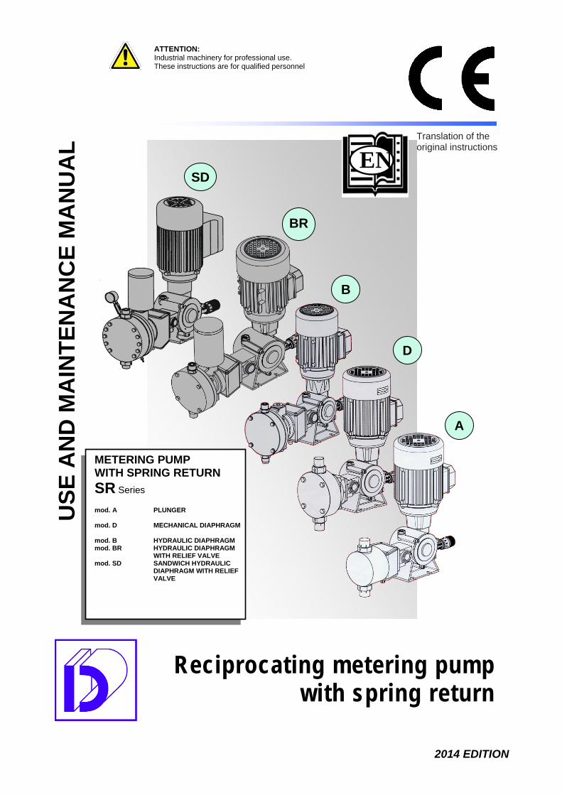
DECLARATION OF CONFORMITY (Annex IIA DIR. 2006/42/EC)
The company DOSEURO®S.r.l.
with headquaters in Via G. Carducci, 141 - 20093 Cologno Monzese (Mi)
Declares under its own responsibility that the products belonging to the following indication of trade.
SPRING RETURN METERING PUMPS Series: SR Model: A-B-BR-SD-D
Comply with the requirements of: Directive 2006/42/EC Machinery Directive (and subsequent modifications) Directive 2004/108/EC Electromagnetic compatibility Directive 2006/95/EC Low voltage directive Directive 2011/95/EU RoHS II And with the following Harmonised Safety Standards:
UNI EN 12100-1:2010 Safety of machinery - General principles for design - Risk assessment and reduction
CEI EN 60204-1:2006 Electrical equipment of machines + Annex 1:2009
The technical file is kept at our office. PLACE AND DATE: Cologno Monzese - 02/12/2013 Person authorized to compile the technical file Signature and position of the declarant BoD Chairman Responsible for the technical management TULLIO MICCICHE’ TULLIO MICCICHE’ Via G. Carducci, 141 Via G. Carducci, 141 20093 Cologno Monzese (Mi) 20093 Cologno Monzese (Mi)
Cert. No. 5942
XMPE0PCG125NST014 1st Edition - 2014 6/28

DOSEURO®
TERMINOLOGY DEFINITIONS AND MEANINGS OF USED SYMBOLS
It is essential to call attention to the symbols used in this manual to highlight the residual risks related to the intended use of the pump. Below are the pictograms indicating the principal warnings and the behaviour that the operator must assume when the symbol is indicated, in order to safely carry out his/her functions.
Features of the safety signs Shape meaning Indications and clarifications
Warning Warns to exercise caution, pay attention to mechanical risks or hazards of various natures present in the work environments.
Prescription Informs workers of the personal protection devices that must be used and the particular behaviour that must be observed.
Symbols ATTENTION! Means that non-compliance with the safety standards may cause minor personal injuries or damage to property. HAZARD! Means that non-compliance with the safety standards may cause personal injuries or damage to property. RISK OF SERIOUS INJURIES! Means that non-compliance with the safety standards may cause serious personal injuries or damage to property.
Minimum qualification of personnel USER The user must be familiar with the machine and the installed safety devices. He/she appoints personnel responsible for machine operation and their operational training, with particular reference to the safety standards. OPERATOR Personnel in charge of the various activities related to the entire life cycle, handling, installation and use of the machine. Deals with the visual check and proper operation of the machine.
ATTENTION!
RISK OF SERIOUS INJURIES!
RESIDUAL RISK!
HAZARD!
RISK OF SERIOUS INJURIES!
2.1
Chapter 2
2.2
XMPE0PCG125NST014 1st Edition - 2014 7/28
DOSEURO®
MECHANICAL MAINTENANCE TECHNICIAN A qualified and authorised person indicating the routine and extraordinary maintenance procedures. He/she must personally and safely perform the disassembly and maintenance of the plant, as well as the installation of the pump on the plant during commissioning. He/she handles the mechanical adjustments, calibrates the machine and replaces any faulty parts. ELECTRICAL MAINTENANCE TECHNICIAN A qualified and authorised person indicating and executing the electrical maintenance procedures and the machine connections to the electrical mains during installation. SAFETY STANDARDS DURING USE This section illustrates the use of the pump in compliance with essential safety standards. To use the metering pump, the installer and operator must carefully read this section in order to guarantee the safety of operators and of the surrounding property. The principal risks related to using the pump are: MECHANICAL:
• Impacts, compression of various body parts, particularly head and limbs. • Falling of objects. • Dangerous vibrations that may injure the operator, damage the machine and harm the
environment in which it is installed. • Accidental insertion of clothing in any moving parts. • Heat produced by the operation or overheating of the pump.
ELECTRICAL: • Contact with distribution and power supply cables. • Live metal elements due to an electrical fault • Static electricity.
PLANT:
• Breakage or leakage from piping located above the pump with corrosive liquid outflow with
corrosion of the outer parts of the metering pump. (it is advisable to avoid passing the pressurised delivery piping above the pump, should this not be possible, provide a cover).
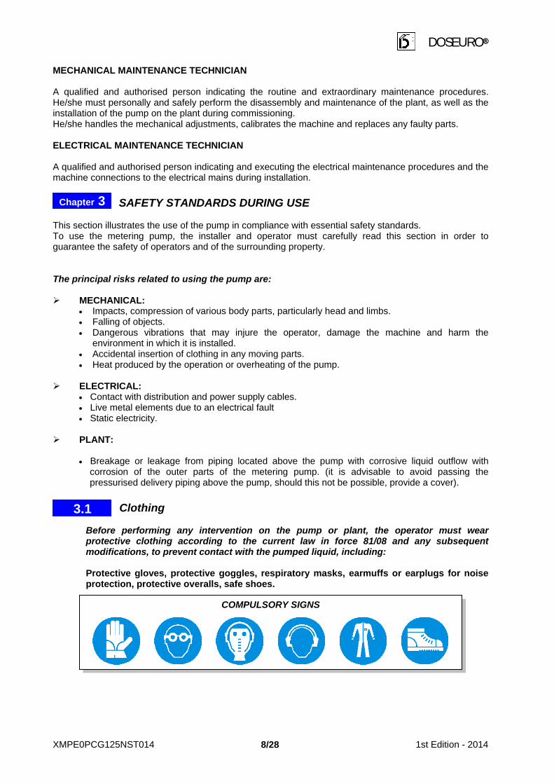
Clothing Before performing any intervention on the pump or plant, the operator must wear protective clothing according to the current law in force 81/08 and any subsequent modifications, to prevent contact with the pumped liquid, including: Protective gloves, protective goggles, respiratory masks, earmuffs or earplugs for noise protection, protective overalls, safe shoes.
USING THE METERING PUMPS
Chapter 3
COMPULSORY SIGNS
3.1
XMPE0PCG125NST014 1st Edition - 2014 8/28

DOSEURO®
USING THE METERING PUMPS Destination of use Any other use outside of that agreed with the sales department during the defining phase, will not be acknowledged by the manufacturer. The Company DOSEURO® declines any liability in case of personal injury or property damage deriving from the incorrect or improper use of the pump. If the pump is to be used for other processes the customer must, to be able to re-use it, request information from our technical department on the compatibility of the materials for correct use. Intended and non-intended use of the pump The pump must be used for the range of applications for which it is intended. Principally that of dosing liquid substances compatible with the materials with which the pump is prepared. Conditions of use The power of the motor installed on the pump is suitable for operation below 1,000 m above sea level and at an ambient temperature ranging from +5°C to +40°C. If the pump is installed at an altitude of over 1000 m a.s.l., the motor power will be inversely proportional to the altitude as represented in the diagram. Consult our technical department during the purchasing phase. Pump description The pump is made up of: Reducer unit: Reduces the number of motor revolutions to that required for metering, by
transforming the rotary motion into a reciprocating rectilinear motion by means of an eccentric shaft, with slide and return spring.
Movement transmission: Aluminium flexible coupling. Adjustment: Plunger stroke from "0%" to "100%" is obtained by turning the knob on
the screw that partialises the slide return, either with the pump stationary or in motion.
Hydraulic head: Sucks the liquid from the inlet valve and pushes it through the delivery valve.
Electric motor: Three-phase or single-phase (CVE – ex proof – Gr. B14 – Cl. F- 50/60 Hz- IP 55 or higher
Pump body: Die-cast aluminium. Hydraulic parts: Plastic or metal materials based on product compatibility.
Chapter 4
HAZARD!
4.4
4.1
RISK OF SERIOUS INJURIES!
4.2
4.3
Pow
er
Height above sea level m.a.s.l.
XMPE0PCG125NST014 1st Edition - 2014 9/28

DOSEURO®
Machine description 4.3.1 PRINCIPLE OF OPERATION The metering pumps are reciprocating positive displacement pumps with a controlled volume. The reciprocating motion determines a sinusoidal supply of the flow rate, therefore, the pumped product flow is not continuous but pulsating. The flow rate or volume of the pump is controlled by varying the plunger/diaphragm stroke. The reciprocating motion of the metering pump plunger/diaphragm determines the flow thanks to the directional valves located at the pumping head's inlet and outlet. The fluid is pumped in the following phases: SUCTION PHASE:
During the suction phase, the valve located at delivery closes (sealing the leak) and the valve at suction opens. The fluid enters the head chamber. The theoretical volume is equal to the plunger displacement.
DISCHARGE PHASE: During the discharge phase, the valve located at the suction side closes and the valve at the delivery side opens. The fluid exits the head and enters the delivery piping. The theoretical volume is equal to the plunger displacement.
FLOW RATE: The flow rate value depends on the following parameters:
1 Number of strokes completed by the plunger per minute (depends on chosen pump model). 2 Plunger stroke and displacement adjustable on pump. 4.3.2 FORMULA OF THE THEORETICAL FLOW RATE The theoretical flow rate expressed (in l/h = litres/hour) is obtained from the operation parameters with the following formula:
Q = S•C•N•60
Where the symbols have the following meaning: Q = Flow rate (in l/h) S = plunger section (in dm2) C = plunger stroke (in dm) N = Number of strokes per minute. 4.3.3 EFFECTIVE FLOW RATE
The effective flow rate is lower than the one theoretically calculated. To switch from the theoretical to the actual flow rate, multiply by the volumetric efficiency with a variable value ranging from 70% to 98%, depending on the model, pressure and materials.
4.5
XMPE0PCG125NST014 1st Edition - 2014 10/28

DOSEURO®
Identification plate Each pump is identified by model, serial number and year of manufacture which can be found on the appropriate plate applied to the pump.
Identification data of type of standard pump 1 Series of pertinence 2 Plunger stroke
3 Plunger diameter
4 Reduction ratio
5 Materials used
6 Type of valve (if single, not indicated)
7 Other accessories supplied
N.B.: for commercial requirements, the pump initial may be different from the standard. Given their importance, the following warnings must be considered:
Never remove the plate from its original position. Do not modify or counterfeit the technical data. Do not clean the plate using abrasive products to avoid eliminating the reported data.
All elements on the plate must remain readable at all times. Use the identification data to request spare parts, technical information and assistance. The loss of this data may void the product's CE conformity as this is where the compulsory CE MARKING is positioned (with possible disputes in case of inspections by the safety and supervisory authorities), should this occur, the user must warn the manufacturer of this loss, identifying the pump from the technical documentation provided with the machine or from the administrative documents. Request a new one from the DOSEURO assistance service. TRANSPORT Always keep the packaging in a vertical position. This model's pumps are individually packaged; customised packaging can be realised only upon request. The customer normally chooses the carrier; therefore, the customer and carrier will be responsible for transportation. Lifting and handling Having to lift the packaging, it is essential for the operator to assess the container features, the route to be travelled or assess the need for other operators to transport the load better. To lift the load, even if it is not heavy, use trucks with a minimum capacity higher than the declared weight of the pump complete with packaging.
4.6
5.1
RISK OF SERIOUS INJURIES!
B 125N - 25/F 11 DV
B 125N - 25/F 11 DV
1 2 3 4 5 6 7
ATTENTION!
Chapter 5
ATTENTION!
XMPE0PCG125NST014 1st Edition - 2014 11/28

DOSEURO®
Personnel in charge of handling the load must wear protective gloves and accident-prevention shoes. Material storage Should the pump remain out of service for a long period, especially before start-up, we recommend re-packaging the material and filling the reducer with SAE 85W-140 oil in order to avoid oxidation of the internal components. The equipment must be stored in a dry, ventilated environment, away from heat sources and at a temperature ranging between +5°C and +40°C. Handling for installation The manual contains all the necessary information for installing the metering pump, taking into account all safety aspects. Before handling the pump, check:
• The efficiency of the lifting means and their capacity. • During lifting or moving of the pump, it is necessary to take all possible care in order to avoid
dangerous movements that may cause personal injuries or damage to property. PUMP INSTALLATION Optimum conditions for installation • Should the pump be installed outdoors, an adequate protective shelter is essential to avoid exposure
to sunlight or rain. • If the pump operates indoors, an average level of lighting is important for the safety of people and to
guarantee the quality of the work and the correct perception of the symbols and markings. Pump location Provide sufficient space (minimum operating areas) to easily inspect and calibrate the pump or disassemble the hydraulic part (valves and pumping head). The pump must be placed above a sturdy base (metal, cement,
etc.), stable and properly levelled, avoiding axis tensions. Ensure that the piping along the path does not create choking
and tension on the axis of the valves, caused by a misalignment. PUMP CONNECTION TO PLANT PIPING Removal of guards It is necessary to remove the protective caps, located on the suction and delivery inlets of the valves, before installing the pump. If the pump has been out-of-service for a long period, we recommend checking that the pumping head screws are not loose as well as checking for oil leaks from the seal gaskets, replacing them if necessary, before installation.
5.2
5.3
Chapter 7
RISK OF SERIOUS INJURIES!
Chapter 6
6.1
6.2
7.1 PROTECTION
CAP
VALVE
PUMP-HEAD
XMPE0PCG125NST014 1st Edition - 2014 12/28

DOSEURO®
Connection to the suction piping Suggestions that the installer must follow for proper installation are listed. • Before connecting the piping to the pump connections, clean the piping to eliminate any foreign
bodies, welding beads, gasket scraps, etc. • The suction piping length must be reduced to an absolute minimum in a linear manner, using large-
radius curves. • Avoid counterslopes to favour the evacuation of any air bubbles and to ensure that the piping is
perfectly sealed, especially in order to avoid the disengagement of the pump. • The suction piping and fittings must be sized to a nominal diameter immediately above that of the
pump valve. • The maximum speed of the fluid in the piping must not exceed 0.7 m/s for liquids with a viscosity of
up to 100 mPa - (cPs). • The piping must be adequately supported to avoid burdening the weight on the pump or creating
tensions on the pumping head. Table for selecting the inner diameters of the piping according to product viscosity and number of pump strokes.
Fluid with viscosity equal to
100 / 300 mPa (CP) - 20 / 45°E 0 / 100 mPa (CP) - 20°E Water +15°C Strokes min/1' Strokes min/1' Strokes min/1'
Minimum inner pipe diameter
from 35 to 45 from 46 to 70 from 96 to 120 Flow rate l/h Flow rate l/h Flow rate l/h
Ø 4 0 – 3 0 – 5 0 – 12 Ø 6 0 – 11 0 – 18 0 – 45 Ø 8 0 – 23 0 – 40 0 – 96 Ø 10 0 – 53 0 – 90 0 – 220 Ø 13 0 – 93 0 – 155 0 – 380 Ø 16 0 – 120 0 – 200 0 – 500 Ø 20 0 – 170 0 – 280 0 – 700 Ø 25 0 – 250 0 – 420 0 – 1050 Ø 32 0 – 290 0 – 480 0 – 1200
7.2
ATTENTION!
XMPE0PCG125NST014 1st Edition - 2014 13/28

DOSEURO®
EXAMPLES OF SUCTION PIPING CONNECTION
CORRECT APPLICATION INCORRECT APPLICATION
EXAMPLES OF SUCTION PIPING CONNECTION
CORRECT APPLICATION INCORRECT APPLICATION
Sucks deposits from the bottom
Interrupts the fluid flow
Acceptable execution
Acceptable solution
XMPE0PCG125NST014 1st Edition - 2014 14/28

DOSEURO®
Connection to the delivery piping The proper realisation of the path and fixing of the delivery piping is particularly important for the proper operation of the pump. In this regard, we list suggestions which the installer must follow to efficiently realise the plant.
• The piping path must be as linear as possible and be independently supported, ensuring that expansion due to heat sources does not occur on the pump's head.
• We recommend always providing one or more "T fittings" at the delivery side that can be used to install pressure gauges, safety relief valves, pulsation dampeners.
• Always provide a safety relief valve and a bleed valve on the delivery circuit in order to protect the plant, facilitate maintenance and the start-up of the pump.
EXAMPLES OF DELIVERY PIPING CONNECTION
CORRECT APPLICATION INCORRECT APPLICATION
DESCRIPTION OF STANDARD PLANT ACCESSORIES
KEY 1) Pulsation dampener 2) Pressure gauge 3) Safety relief or overpressure valve 4) Sampling or draining 5) 45° "Y" Filter 6) Flowmeter 7) Back pressure valve The control of the fluid dynamics is essential to guarantee efficiency and use of the process system. Not controlling the moving fluids may result in the dosing system, including the pumps and any valves, flowmeters, instruments or other equipment installed on the line, being physically destroyed. The correct choice of the accessories and their sizing, ensures the efficiency and life-span of the system.
7.3
Chapter 8
Funnel Vent valve The sole delivery valve is not enough to avoid piping.
The main piping under pressure damages the secondary piping and the pump. Injection valve
ATTENTION!
XMPE0PCG125NST014 1st Edition - 2014 15/28
DOSEURO®
Each metering pump can be fitted with accessories to improve its operation and accuracy. The benefits obtained from a correct installation and an accurate control are: - Increase of efficiency and life-span of the pump - Reduction of interventions and maintenance costs 8.1 - PULSATION DAMPENER The metering pumps have the pulsating flow rate characteristic, as each pumping cycle provides a suction and a discharge phase. Various benefits are obtained by installing a pulsation dampener: - Pump protection against pressure peaks; - Elimination of vibrations along the length of the delivery piping; - A flow rate with a smoother flow useful for the process. With consequent benefit on the duration of the pump's life-span 8.2 - PRESSURE GAUGE Instrument for measuring any pressure higher than that of the atmosphere used for liquids and gas and installed on a shunt on the delivery piping of the metering pumps. It is necessary for setting the safety relief valve's pressure value, which enables the user to determine the effective working pressure of the pump. Constant pressure monitoring and a flow rate check are used to verify the proper operation of the pump. 8.3 - SAFETY RELIEF VALVE The safety relief valves are used to protect the pump and the plant from possible damage caused by overpressure deriving from defective accessories or obstructions in the plant's piping, caused by sediments or the accidental closing of a shut-off valve. The safety relief valve on the delivery piping must be installed immediately after the pump's coupling and before the shut-off valve. However, the application of the safety relief valve is essential for the above reasons as well as for standards relating to accident prevention in the workplace. 8.4 - SAMPLING OR DRAINING Sampling or draining is carried out by mounting the shut-off valve in a shunt on the delivery piping which discharges in the open-air. It is mainly used to drain the delivery piping from the dosed fluid when performing plant maintenance or to take a sample of the liquid for flow rate tests. 8.5 - FILTER Accessory with the function of retaining the impurities present in a flowing fluid. We recommend installing the filter (on the suction piping) in order to prevent the impurities that may be present in the liquid from being dosed from the piping, which may unable the proper operation of the valves, thus causing irregular flow or passage obstructions. The size of the filter mesh must be chosen based on the impurities present. While the filter surface is related to the product flow rate, paying attention to the fact that the smaller the filter surface and the mesh dimension, the higher the load losses produced by the filter will be. Do not place the suction piping connection on the bottom of the tank to avoid sucking impurities, but ensure that the suction area is at a height of at least 10 cm from the bottom. 8.6 - FLOWMETER
It is an instrument consisting of a transparent plexiglas casing with a graduated scale and a float inside to visually indicate the dosed amount (volumetric flow) for an immediate check of the adjusted dosing volume. At his/her discretion, the customer may install other types of flowmeters deemed more appropriate for his/her plant. 8.7 - BACK PRESSURE VALVE
The back pressure valve is required to prevent the spontaneous passage of liquid (siphoning) in conditions in which the suction tank level is higher than that of delivery.
XMPE0PCG125NST014 1st Edition - 2014 16/28

DOSEURO®
8.8 - SHUT-OFF VALVE IN DELIVERY PIPING The shut-off valve is used to shut-down the flow of dosed liquid by closing the pump's delivery line The metering pumps are reciprocating positive displacement pumps. Regardless of whether the delivery piping has been closed, e.g. by closing the delivery piping or a valve, the pressure produced by the pump may sometimes exceed the admitted working pressure value of the plant or of the metering pump. This may cause the piping to explode with dangerous consequences especially in the presence of toxic or aggressive substances! Install safety devices on the system, e.g. safety relief/vent valves in the presence of a shut-off valve in the delivery piping! LUBRICATION For transport the pump is supplied without lubricating oil. Before commissioning, the operator must fill with oil. Due to the viscosity, the oil must be slowly poured to avoid exceeding the level indicated by the warning light. The pump does not have other lubrication points, so the amount set-out in the table is sufficient to guarantee good lubrication. We recommend carefully handling the product, using adequate protective clothing, especially when draining the oil contained in the reducer body . The type of oil that we recommend for the reducer must have the following characteristics: high viscosity and fluidity when cold, defined with initial:
SAE 85 W-140 - viscosity cSt +40°C 328 - flash point +224°C Amount of oil to be introduced in the pump's body
Model Oil Q.ty ml
1st change h
2nd change
h A 125A/ A 125N/ B 125N/ BR 125N/ SD 125N/ S 050N/ D 050N/
D 100N 150 500 3,000
A 175 A/A 175N/ B 175N/ BR 175 N/ SD 175N/ D 101 N/ D 121N 300 500 3,000 A 250N/ A 350N / B 250N/ BR 250N/ SD 250N 650 500 3,000
Some brands and their initials are featured for exemplification purposes:
TYPES OF EQUIVALENT OILS Esso Gear Oil GX 85W 140 BP Hypogear EP 85W 140
Mobil Mobilube HD 85W 140 IP Pontiax HD 85W 140
Shell Spirax A 85W 140 Agip Rotra MP 85W 140 N.B.: for maintenance and the filling of oil chambers for the various types of hydraulic diaphragm pumps, B – BR - SD type, refer to the use and maintenance manual for the heads.
Chapter 9
Level max.
Fill oil
ATTENTION!
RESIDUAL RISK!
XMPE0PCG125NST014 1st Edition - 2014 17/28

DOSEURO®
ELECTRICAL CONNECTION The installer must provide an adequate electric line cut-out switch upstream of the pump and use cables with a sufficient section to support the maximum current absorbed by the motor. Suitable devices must be installed with a delayed release to protect against overheating in case of a blocked rotor, as prescribed by Standard EN 60079-14. Connections, commissioning, maintenance, measurements and adjustments of the electric equipment or of its components must be carried out by qualified electrical maintenance technicians only. Comply with the relative standards in force to perform work on live parts.
Motor connection Refer to the instructions in the terminal board before making the motor connections and check that: • The voltage and frequency of the main power supply correspond to those indicated on the motor
plate. • The earth terminal is connected to the protective conductor. • The motor's running direction corresponds to the direction of the arrow on the fan cover. • The vicinity of obstacles does not prevent proper ventilation of the motor and make the
maintenance and inspection operations difficult. Qualified personnel must make the electrical connection with the utmost caution, with the mains switched off and in compliance with the safety requirements. It is essential to connect the pump to an efficient and controlled earth line.
DIAGRAM OF MOTOR CONNECTION TO ENERGY SOURCES
10.1
RISK OF SERIOUS INJURIES!
Chapter 10
THREE PHASE MOTOR STAR CONNECTION
SINGLE PHASE MOTOR CLOCKWISE ROTATION
Exchange connection of L1 – L2 cables to invert motor rotation
DELTA CONNECTION COUNTER-CLOCKWISE
ROTATION
XMPE0PCG125NST014 1st Edition - 2014 18/28
DOSEURO®
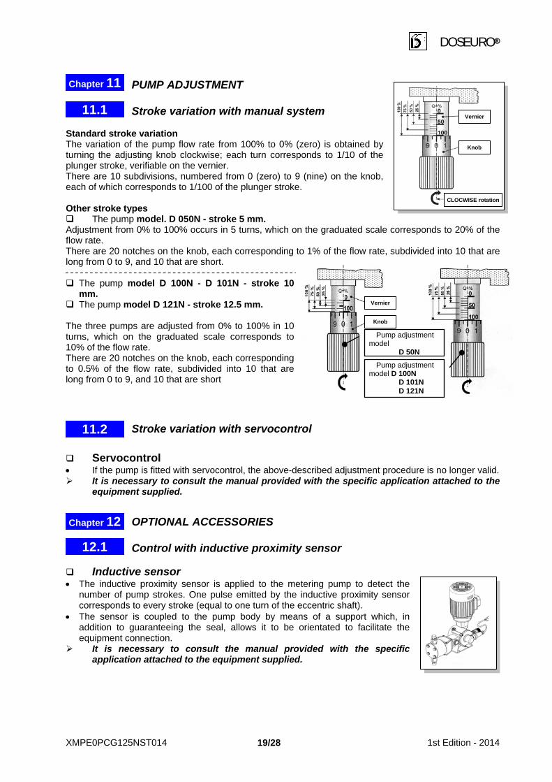
PUMP ADJUSTMENT Stroke variation with manual system Standard stroke variation The variation of the pump flow rate from 100% to 0% (zero) is obtained by turning the adjusting knob clockwise; each turn corresponds to 1/10 of the plunger stroke, verifiable on the vernier. There are 10 subdivisions, numbered from 0 (zero) to 9 (nine) on the knob, each of which corresponds to 1/100 of the plunger stroke. Other stroke types The pump model. D 050N - stroke 5 mm. Adjustment from 0% to 100% occurs in 5 turns, which on the graduated scale corresponds to 20% of the flow rate. There are 20 notches on the knob, each corresponding to 1% of the flow rate, subdivided into 10 that are long from 0 to 9, and 10 that are short. The pump model D 100N - D 101N - stroke 10
mm. The pump model D 121N - stroke 12.5 mm. The three pumps are adjusted from 0% to 100% in 10 turns, which on the graduated scale corresponds to 10% of the flow rate. There are 20 notches on the knob, each corresponding to 0.5% of the flow rate, subdivided into 10 that are long from 0 to 9, and 10 that are short
Stroke variation with servocontrol Servocontrol • If the pump is fitted with servocontrol, the above-described adjustment procedure is no longer valid. It is necessary to consult the manual provided with the specific application attached to the
equipment supplied. OPTIONAL ACCESSORIES Control with inductive proximity sensor Inductive sensor • The inductive proximity sensor is applied to the metering pump to detect the
number of pump strokes. One pulse emitted by the inductive proximity sensor corresponds to every stroke (equal to one turn of the eccentric shaft).
• The sensor is coupled to the pump body by means of a support which, in addition to guaranteeing the seal, allows it to be orientated to facilitate the equipment connection.
It is necessary to consult the manual provided with the specific application attached to the equipment supplied.
11.1
Chapter 11
Chapter 12
11.2
12.1
Pump adjustment model D 100N D 101N D 121N
Pump adjustment model D 50N
Vernier
Knob
CLOCWISE rotation
Vernier
Knob
XMPE0PCG125NST014 1st Edition - 2014 19/28

DOSEURO®
PROCEDURE BEFORE START-UP Personnel must be aware of the product to be dosed and observe the due precautions when handling chemical products used in the process, whether they are (acids, bases, oxidation-reducers, etc.). Verification before start-up
• Check pump fixing on its support. • Make sure the oil in the pump body is visible from the warning light. • Check that the liquid to be dosed is not solidified or frozen in the piping. • Check that all shut-off valves on the suction or delivery circuits are open. If the delivery circuit is
fitted with a back pressure and injection valve, open the bleed valve at the delivery side to allow for the priming of the pump
• Adjust the pump flow rate to 0%. Verification of the motor's electrical connection.
• Start the pump, checking that the rotating direction of the motor is the same as the direction of the arrow located on the fan cover. If it is in opposite direction, reverse the electric power supply cables L1 - L2 as per the diagram.
Commissioning After all of the checks described in the previous chapter have been carried out, start the pump.
• Progressively adjust the pump flow rate from 0% to 100%, verifying: The leakage of fluid from the bleed valve (where present). The noise produced by the liquid as it crosses the delivery valve.
• As soon as the liquid leaks, close the bleed valve (where present). • Carry out a visual and auditory check (for dripping or suspicious noises). • Check the piping is well supported, does not produce vibrations and, above all, does not exert
tensions on the pump head. • With start-up at a low temperature, adjust to 0% and leave the pump running in this condition for
at least 5 minutes, this allows for the heating of the pump which eliminates motor condensation and heats the oil. Then progressively adjust the flow rate up to the flow rate value required by the process.
Inconveniences upon commissioning The motor turns with difficulty and heats:
• The features of the motor's electric power supply do not correspond to those on the plate or the chosen connection is inadequate.
• Check that the delivery pressure corresponds to that of the project. The flow rate is below that desired:
• Incorrect pump flow rate adjustment: adjust the flow rate to the desired value. • Insufficient suction due to the excessive length of the piping or to a section that is too small. We
recommend replacing the piping with the necessary section or positioning the pump under the head and as close as possible to the suction source.
• The suction piping seal is not perfect (possible air infiltrations). • The liquid viscosity is not compatible with the pump version or the filter is clogged.
The flow rate is above that desired: • Siphoning phenomena occurs: check that the suction pressure is not higher than that of the
delivery pressure. Install a back pressure valve on the delivery circuit. The flow rate is variable:
• The problem may be due to solid particles coming from the piping or sediments in suspension which prevent the perfect closure of the pump valves. Good cleaning and the installation of a filter on the suction piping is recommended.
ATTENTION!
13.1
13.2
Chapter 13
XMPE0PCG125NST014 1st Edition - 2014 20/28

DOSEURO®
MAINTENANCE Maintenance is a combination of all technical and administrative actions, including supervision, aimed at maintaining or returning a machine to a condition in which it can perform the required function. See the relative use and maintenance manuals of the plunger heads or diaphragm heads attached to this manual for pump head maintenance. List of spare parts To correctly and easily identify the spare parts, refer to the drawings of the mechanism attached to the pump manual. In their absence, request them from DOSEURO referring to the plate located on the pump to identify the model, serial number and year of manufacture. The inspection and maintenance program depends on the conditions of use of the pump. Good maintenance allows for the best possible performance, longer working duration and a constant observance of the safety requirements. To facilitate recording the maintenance or inspection operations, we attach an intervention recording sheet template
METERING PUMP MAINTENANCE SHEET
PUMP TYPE: ……………………….. SERIAL NO.: …………………… ITEM: ……………………… Liquid Date Date of pumped: …………………………….. installation: ……………………. commissioning: ……………….. Period of intervention: ………………………………………………………. Date:………………………..
FREQUENCY COMPONENT TYPE OF INTERVENTION ACTION
ATTENTION!
Chapter 14
14.1
XMPE0PCG125NST014 1st Edition - 2014 21/28
DOSEURO®
PREVENTIVE MAINTENANCE To ensure that the pump is safe and performs well at all times, it must be subjected to maintenance interventions consisting in visual checks. • Make sure that the external parts of the pump are not corroded or degraded (cracks, crevices,
breaks). In the presence of these problems, replace the worn parts. • Should the pump be used in particularly harsh fields of application where the presence of aggressive
or particularly abrasive liquids drastically reduces the life of the gaskets or of the valve units, the maintenance frequency must be increased. Particularly if in the presence of products that cause problems of "Crystallisation", once the pumping cycle is complete, wash thoroughly to ensure that the product does not solidify and damage the seal gaskets. By transcribing the details on the "Maintenance Record", the operator can tailor the interventions more accurately.
Noisy mechanics with vibrations If abnormal noise is heard inside the pump body, we recommend immediately stopping the pump and, after having checked the overall diagram and the prescriptions, perform the intervention.
• The cog wheel is worn: replace together with the worm screw. • The bearings are noisy: replace them.
Electric motor
Checking the motor and its parameters serves to eliminate any malfunctions and avoids the consequent blocking or lowering of the operation metering pump parameters. The parameters to be periodically checked are the voltage, amperage (absorption of motor phases) and its heating during normal operation (the numerical values relating to the motor are shown on the plate fixed to the motor body). This is used to check the mechanical condition of the motor to avoid the breaking of the bearings, shaft misalignment (motor vibrations transmitted to the pump coupling). In case of abnormal motor heating:
• The pump works at different conditions or at a higher pressure than that of the project. • Insufficient amount of oil in carter: check for leaks and restore the level.
Checking of flexible coupling Irregular machine operation or vibrations affecting torque loads, these hitches may jeopardise the life of the coupling. After the initial installation, we recommend checking the coupling at short intervals during the machine downtime period. Disassemble the motor, check the flexible ring surfaces are not worn or crushed. Verification of pump flow rate This is a check of the pump's flow rate curve according to the adjustment, as it is an essential parameter together with the verification of the working pressure to check the regular operation of the pump and of the process. Three measurements are sufficient: adjustment to 100% - 50% - 25%.
• Install a flow rate calibrator at the pump's suction, measure the pumped liquid volume in a certain period and in normal operating conditions.
• For a constant and precise monitoring of the working process, we recommend installing a flowmeter, electronic is preferable.
Chapter 15
15.2
15.3
15.1
15.4
XMPE0PCG125NST014 1st Edition - 2014 22/28
DOSEURO®
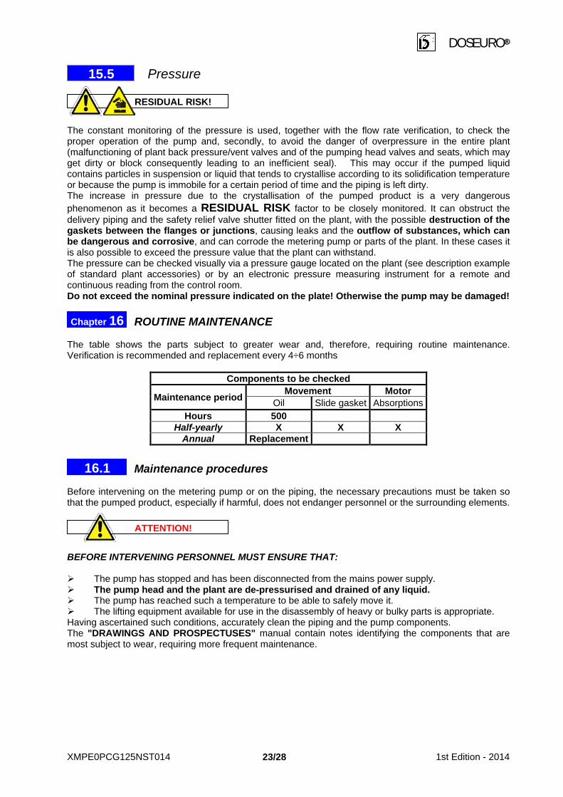
Pressure The constant monitoring of the pressure is used, together with the flow rate verification, to check the proper operation of the pump and, secondly, to avoid the danger of overpressure in the entire plant (malfunctioning of plant back pressure/vent valves and of the pumping head valves and seats, which may get dirty or block consequently leading to an inefficient seal). This may occur if the pumped liquid contains particles in suspension or liquid that tends to crystallise according to its solidification temperature or because the pump is immobile for a certain period of time and the piping is left dirty. The increase in pressure due to the crystallisation of the pumped product is a very dangerous phenomenon as it becomes a RESIDUAL RISK factor to be closely monitored. It can obstruct the delivery piping and the safety relief valve shutter fitted on the plant, with the possible destruction of the gaskets between the flanges or junctions, causing leaks and the outflow of substances, which can be dangerous and corrosive, and can corrode the metering pump or parts of the plant. In these cases it is also possible to exceed the pressure value that the plant can withstand. The pressure can be checked visually via a pressure gauge located on the plant (see description example of standard plant accessories) or by an electronic pressure measuring instrument for a remote and continuous reading from the control room. Do not exceed the nominal pressure indicated on the plate! Otherwise the pump may be damaged! ROUTINE MAINTENANCE The table shows the parts subject to greater wear and, therefore, requiring routine maintenance. Verification is recommended and replacement every 4÷6 months
Components to be checked
Maintenance period Movement Motor Oil Slide gasket Absorptions
Hours 500 Half-yearly X X X
Annual Replacement Maintenance procedures Before intervening on the metering pump or on the piping, the necessary precautions must be taken so that the pumped product, especially if harmful, does not endanger personnel or the surrounding elements. BEFORE INTERVENING PERSONNEL MUST ENSURE THAT: The pump has stopped and has been disconnected from the mains power supply. The pump head and the plant are de-pressurised and drained of any liquid. The pump has reached such a temperature to be able to safely move it. The lifting equipment available for use in the disassembly of heavy or bulky parts is appropriate. Having ascertained such conditions, accurately clean the piping and the pump components. The "DRAWINGS AND PROSPECTUSES" manual contain notes identifying the components that are most subject to wear, requiring more frequent maintenance.
ATTENTION!
16.1
Chapter 16
RESIDUAL RISK!
15.5
XMPE0PCG125NST014 1st Edition - 2014 23/28

DOSEURO®
Residual risks • In case of breaks, once the plant is drained, de-pressurise the pump head, clean with adequate
means (sleeve) and substances compatible with the product. Only then disassemble the pump, not forgetting that the operator must wear adequate protective clothing (gloves, goggles, boots, overalls, etc.).
DECOMMISSIONING OF THE PUMP Should it be necessary to decommission the pump, it is important to observe certain essential rules to protect the product and the operating personnel. Before disposal, an accurate cleansing with liquids compatible with the pumped liquid is necessary as there may be residues of toxic, caustic and acid liquids or sediments that can easily crystallise. Before removing the pump from the plant, de-pressurise the plant, drain the liquid from the circuit,
shut-off the piping near to the pump. Dispose of the residual substances or machine parts following the existing legal procedures to
guarantee the safety of operators and prevent possible negative effects on the environment. DISPOSAL OF COMPONENTS AND HARMFUL SUBSTANCES The user is advised that the separation of the materials and their recycling must be carried out in compliance with National and Regional Laws on disposal, consigning waste, subject to authorisation for temporary storage, to disposal sites belonging to the authorised consortium. To ensure that there are no residual risks of environmental pollution, the materials used for the production process, particularly the lubricant, must be stored and disposed of in compliance with national laws. The adequate separate collection favours the recycling of the materials of which the equipment is composed and contributes to the avoidance of possible negative effects on the environment. Before sending worn components for disposal, it is good practice to adequately clean them to avoid polluting the environment. REPAIR MAINTENANCE In the majority of cases, the replacement of worn parts is not operationally difficult. Before the intervention the operator must refer to the drawings in the manual (DRAWINGS AND PROSPECTUSES) and follow the instructions therein. If the fault is difficult to resolve in the operational area, it is recommended to send the pump to our workshop.
Chapter 17
Chapter 18
ATTENTION!
RESIDUAL RISK!
17.1
16.2
XMPE0PCG125NST014 1st Edition - 2014 24/28
DOSEURO®
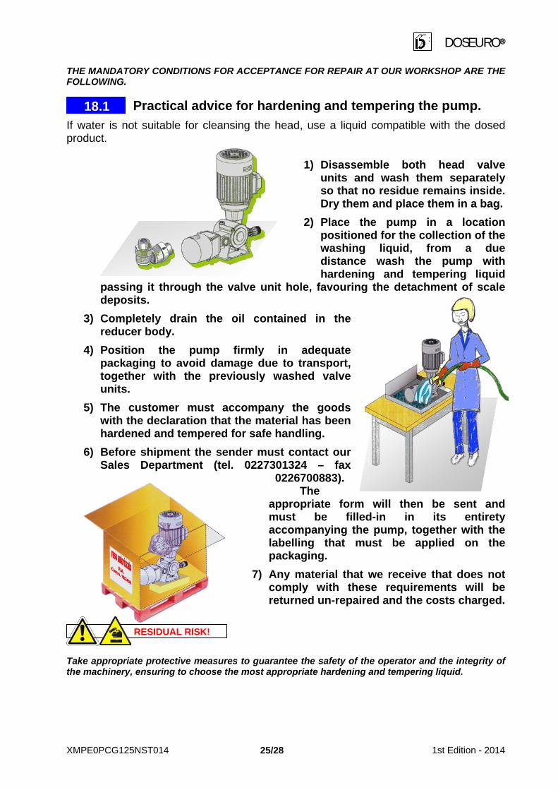
THE MANDATORY CONDITIONS FOR ACCEPTANCE FOR REPAIR AT OUR WORKSHOP ARE THE FOLLOWING. Practical advice for hardening and tempering the pump. If water is not suitable for cleansing the head, use a liquid compatible with the dosed product.
1) Disassemble both head valve units and wash them separately so that no residue remains inside. Dry them and place them in a bag.
2) Place the pump in a location positioned for the collection of the washing liquid, from a due distance wash the pump with hardening and tempering liquid
passing it through the valve unit hole, favouring the detachment of scale deposits.
3) Completely drain the oil contained in the reducer body.
4) Position the pump firmly in adequate packaging to avoid damage due to transport, together with the previously washed valve units.
5) The customer must accompany the goods with the declaration that the material has been hardened and tempered for safe handling.
6) Before shipment the sender must contact our Sales Department (tel. 0227301324 – fax
0226700883). The
appropriate form will then be sent and must be filled-in in its entirety accompanying the pump, together with the labelling that must be applied on the packaging.
7) Any material that we receive that does not comply with these requirements will be returned un-repaired and the costs charged.
Take appropriate protective measures to guarantee the safety of the operator and the integrity of the machinery, ensuring to choose the most appropriate hardening and tempering liquid.
RESIDUAL RISK!
18.1
XMPE0PCG125NST014 1st Edition - 2014 25/28

DOSEURO®
INFORMATION FOR USERS Pursuant to art. 13 and Legislative Decree 25 July 2005, no. 151, Implementation of Directives 2002/95/EC, 2002/95/EC, 2003/108/EC relating to the reduction of use of dangerous substances in electric equipment, as well as waste disposal.
The crossed-out bin symbol illustrated on the equipment indicates that the product, at the end of its function, cannot be disposed of as normal domestic waste. The user must take the equipment to suitable separate collection centres for electric waste. The adequate separate collection helps to avoid any possible negative effects on the environment and health as well as favouring the recycling of the materials of which the equipment is composed. The illegal disposal of the product by the user entails the application of administrative sanctions under "art. 255 Leg. Decree no. 152/2006.
Chapter 19
XMPE0PCG125NST014 1st Edition - 2014 26/28

DOSEURO®
NOTES:
XMPE0PCG125NST014 1st Edition - 2014 27/28
DOSEURO®
Cert. No. 5942
For a better use of your metering pump, choose:
DOSEURO®S.r.l ACCESSORIES. Request them to our Sales Department
Doseuro®S.r.l.
The Right Dosing Choice Via G. Carducci, 141 - 20093 Cologno Monzese (Mi) - Italy
Tel. +39 0227301324 - Fax. +39 0226700883 http://www.doseuro.com e-mail: [email protected]
XMPE0PCG125NST014 1st Edition - 2014 28/28
ETA Ekipman Teknoloji Ar. Sis. San. Tic. Ltd. Şti.
www.etaekipman.com blog.etaekipman.com
Tel:0 216 540 99 64 Fax:0 216 540 99 68