Embed Size (px)
Citation preview

ECAL SLAB Interconnect
Update on Investigations at Cambridge
● Recapcap
● Lines of Enquiry
● Bits and Boards
● Where we are
Maurice Goodrick & Bart Hommels , University of Cambridge

ECAL SLAB Interconnect - Recap
We have been looking at using “Bridges” to jumper multiple connections betweenjumper multiple connections between adjacent ASUs
The Bridge would be soldered onto pads on g pthe ASU (or DIF) PCB
Each Bridge would provide >=30 connectionsU 4 B id fi i h id h f ASUUp to 4 Bridges fit in the width of an ASU… 1 per path would be an ideal solution ☺☺p p
Maurice Goodrick & Bart Hommels , University of Cambridge

ECAL SLAB Interconnect - Recap
Short FFC (Flat,Flexible-Cable) Bridges make connections on a 1mm pitch OK for at least 120 connectionson a 1mm pitch – OK for at least 120 connections
FFC-Bridge SolderTrack
ASU ASU800um
Track
Alternatively the Bridges can be thin PCBs, also with 1mm y gpitch connections. This gives a mechanical as well as electrical joint
PCB-Bridge SolderTrack
ASU ASU800um
Track
Maurice Goodrick & Bart Hommels , University of Cambridge

ECAL SLAB Interconnect - Recap
● Provides copious connections (4 x 30 across ASU)l f P Pl● plenty for Power Planes
● would allow 4 or more rows of connectionsS ld j i ll l i ll● Solder joints well proven electrically
● Signal transmission likely to be less compromisedR k ibl● Rework possible
Usi FFC B id ld k th h i l● Using an FFC-Bridge would make the mechanical joint independent: this might appeal to the m h i l d si smechanical designers
Usin PCB B id mbin s m h ni l nd● Using a PCB-Bridge combines mechanical and electrical joint
Maurice Goodrick & Bart Hommels , University of Cambridge

ECAL SLAB Interconnect - Investigations
● How to solder the joints● IR using linear Quartz-Halogen lamp
L S ld i● Laser Soldering
● Signal IntegritySignal Integrity● Signal delivery along LVDS lines
● Crosstalk
Effect on Detector Glue Connections● Effect on Detector Glue Connections● Does soldering cause joint deterioration?g j
● If not, what about rework?
Maurice Goodrick & Bart Hommels , University of Cambridge

ECAL SLAB Interconnect - BitsTop View
Thin traces onThin traces on Kapton backing
Under View
FFC-Bridges: we have 250 cut, 250 on roll
We now cut them in half: only ~6 mm long
Maurice Goodrick & Bart Hommels , University of Cambridge

ECAL SLAB Interconnect - BitsTop View
Variant AVariant BVariant CVariant DVariant EVariant FVariant AVariant AVariant BVariant CVariant DVariant DVariant EVariant F
PCB-Bridges: have 15 Panels of 8 lots of 6 variantsUnder View0.4 mm FR4, Au Plated
gWe cut these in half too: only ~6 mm long
Maurice Goodrick & Bart Hommels , University of Cambridge

ECAL SLAB Interconnect - PCBsTop View Interconnect
region 400um
d l f d ff l180 x 180mm – as current ASU size
4 identical rows of differential tracks connecting 36 way
i t t d l ft d i htinterconnect pads on left and right
b l d 4
Central region thickened to 800um
Can be sliced into 4 sections, so provides for many trials
Differential tracks have a range of spacings & other charcteristics to p gtest signal propagation and cross-
talk
ASU-Test_2 PCB: we have 15
Maurice Goodrick & Bart Hommels , University of Cambridge

ECAL SLAB Interconnect - PCBsTop View Under View Aluminised 300um
Glass plates: we have 9 (plus more
180 x 180mm – as current ASU size
have 9 (plus more un-coated)
3Fo
Central region thickened to 800um
30-way Iootprint Interco
ts (4 pe
Pads on 5mm pitch
onnect er PCB)
5 rows joined These 2 rows
GlueTest PCB: we have 28
5 rows joinedto fingers/pads
These 2 rows “commoned”
Maurice Goodrick & Bart Hommels , University of Cambridge
GlueTest PCB: we have 28

ECAL SLAB Interconnect – Soldering
PCB-Bridges: solder pasting
Maurice Goodrick & Bart Hommels , University of Cambridge

ECAL SLAB Interconnect – Soldering
R fl i PCB B idRe-flowing a PCB-Bridge
Linear Halogen Lamp
Elliptical ReflectorElliptical Reflector
Imaging Halogen IR SourceMaurice Goodrick & Bart Hommels , University of Cambridge
Imaging Halogen IR Source

ECAL SLAB Interconnect – Soldering4 Section ASU-Test Assembly
FFC-Bridge joints
PCB-Bridge joint
View of FFC-Bridge joint
ASU-Test_2: 4 Section Assembly
Maurice Goodrick & Bart Hommels , University of Cambridge

ECAL SLAB Interconnect – Soldering
ASU-Test_2: 10 Section Assembly in Progress
Maurice Goodrick & Bart Hommels , University of Cambridge

ECAL SLAB Interconnect – Crosstalk
Using the 4 Section ASU-Test_2 Assembly
LVDS Drive Circuit: End Term’n = 82RTrack Series Res ~ 8RLVDS Drive CircuitBack Term’n = 100R
End Term n 82R
Length = 4x180mm = 720mm
Track Series Res 8R
Crosstalk SetupMaurice Goodrick & Bart Hommels , University of Cambridge

ECAL SLAB Interconnect – Crosstalk
FarVictim Pr0FarVictimNear Victim
AggressorNear VictimFar Victim
Pr0Pr1Pr2Pr3Pr4
FarVictimNear Victim
AggressorPr5Pr6Pr7
“Twists”
AggressorNear VictimFar Victim
Pr7Pr8Pr9
FarVictimNear Victim
AggressorNear VictimFar Victim
Pr10Pr11Pr12Pr13Pr14Far Victim Pr14
“Twists”
ASU-Test_2: Traces
Maurice Goodrick & Bart Hommels , University of Cambridge

ECAL SLAB Interconnect – Crosstalk
Pair Separation/Group Pair Separation/(Track & Gap)
A 1B 1 5B 1.5C 2D 3D 3
ASU-Test_2: Traces
Maurice Goodrick & Bart Hommels , University of Cambridge

ECAL SLAB Interconnect – Crosstalk
Amplitude:Near: 840mV Far: 650mVFar: 650mV
ASU-Test_2: Aggressor Signal Propagation (Pr2, Group A)
Maurice Goodrick & Bart Hommels , University of Cambridge

ECAL SLAB Interconnect – Crosstalk
Ampl: ~ 8mVAmpl: ~ 8mV
Driver End Far EndDriver End Far End
ASU-Test_2: Victim Crosstalk (Prs 0,1,3,4, Group A)
Maurice Goodrick & Bart Hommels , University of Cambridge

ECAL SLAB Interconnect – Crosstalk
F E dFar End
Near End
ASU-Test_2: Victim Crosstalk Along Slab (Pr 1, Group A)
Maurice Goodrick & Bart Hommels , University of Cambridge

ECAL SLAB Interconnect – Crosstalk
Driver End Far EndDriver End Far End
Greater Pair Separation => Far Less Crosstalk
ASU-Test_2: Victim Crosstalk (Prs 0,1,3,4, Group C)
Maurice Goodrick & Bart Hommels , University of Cambridge

ECAL SLAB Interconnect – Crosstalk
Driver End Far EndDriver End Far End
Crosstalk alternates sign“With Twists”
ASU-Test_2: Victim Crosstalk (Prs 5,6,8,9, Group A)
Maurice Goodrick & Bart Hommels , University of Cambridge

ECAL SLAB Interconnect – Crosstalk
Driver End Far EndDriver End Far End
Crosstalk alternates sign twice as fast“With Extra Twists”
ASU-Test_2: Victim Crosstalk (Prs 10,11,13,14, Group A)
Maurice Goodrick & Bart Hommels , University of Cambridge

ECAL SLAB Interconnect – Crosstalk
Near EndNear End
Far End
ASU-Test_2: Propagation with Added 10pFsat ASU Joints (Pr 2 Group C)
Maurice Goodrick & Bart Hommels , University of Cambridge
at ASU Joints (Pr 2, Group C)
ECAL SLAB Interconnect – Crosstalk
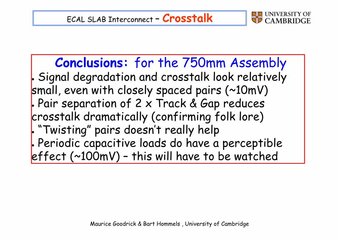
Conclusions: for the 750mm Assembly● Signal degradation and crosstalk look relatively● Signal degradation and crosstalk look relatively small, even with closely spaced pairs (~10mV)● Pair separation of 2 x Track & Gap reduces● Pair separation of 2 x Track & Gap reduces crosstalk dramatically (confirming folk lore)● “Twisting” pairs doesn’t really help● Twisting pairs doesn t really help● Periodic capacitive loads do have a perceptible effect (~100mV) – this will have to be watchedeffect ( 100mV) this will have to be watched
Maurice Goodrick & Bart Hommels , University of Cambridge

ECAL SLAB Interconnect – GlueTest● Marc Anduze provided a number of 300um 90x90 glass plates (plus some of 500um)glass plates (plus some of 500um)● We had 9 of them aluminised● Manchester glued 2 of these to Gluetest PCBs● Manchester glued 2 of these to Gluetest PCBs● We have made initial resistance measurements● Plan is to subject these to the IR soldering● Plan is to subject these to the IR soldering process, and to re-check the resistancesWe find that glue joints are not simple!● We find that glue joints are not simple!
● Ray Thompson of Manchester has written a very useful note on thisuseful note on this● We will use both leaded (183 deg) and Sn-Bi solder (150 deg)solder (150 deg)● If these temperatures are a problem, it might push us to Laser Soldering
Maurice Goodrick & Bart Hommels , University of Cambridge
push us to Laser Soldering

ECAL SLAB Interconnect – GlueTest Initial
I Lim(mA) 50 50 50 50 50 100V Lim (V) 1 2 3 4 1 1
Connector #1
GlueTest - PCB #1IlimVlim
PSU
V Lim (V) 1 2 3 4 1 1Finger
0 9.2 9.2 9.2 9.2 9.1 181 9 9 9 9 9 182 9.6 9.6 9.6 9.6 9.6 193 9.1 9 9 9.1 9 184 1000 2000 3000 22 21 435 1000 114 66 18 17 356 1000 2000 3000 20 20 407 1000 2000 3000 23 23 468 1000 2000 3000 28 27 56
mVDMM
9 1000 160 18 19 19 3810 1000 87 18 18 18 3711 1000 2000 22 24 24 4912 470 31 15 15 14 3013 180 31 17 17 16 3314 1000 2000 33 29 29 5814 1000 2000 33 29 29 5815 1000 2000 3000 22 22 4416 1000 31 16 16 16 3217 1000 2000 3000 18 19 3818 120 27 28 16 16 3319 1000 38 18 18 18 3619 1000 38 18 18 18 3620 1000 2000 3000 18 18 3621 1000 2000 3000 20 20 4122 1000 2000 3000 18 17 3523 1000 2000 15 15 15 3024 1000 2000 19 19 19 3925 215 124 49 40 39 7826 1000 2000 23 16 16 3327 1000 2000 34 24 24 4928 1000 2000 20 21 21 4229 12 12 12 12 12 24
Maurice Goodrick & Bart Hommels , University of Cambridge

ECAL SLAB Interconnect – Laser Soldering
James GilbertUniversity of HullUniversity of Hull
Hull, UK
James GilbertJames GilbertUniversity of Hull
Hull, UKMaurice Goodrick & Bart Hommels , University of Cambridge
Hu , K

ECAL SLAB Interconnect – Laser Soldering
Maurice Goodrick & Bart Hommels , University of Cambridge

ECAL SLAB Interconnect – Laser Soldering
Maurice Goodrick & Bart Hommels , University of Cambridge

ECAL SLAB Interconnect – Laser Soldering
25W 800nm25W, 800nmS/C Laser
X-Y Table
400um Delivery Fibre
Doublet Lens
Maurice Goodrick & Bart Hommels , University of Cambridge

ECAL SLAB Interconnect – Laser Soldering
Maurice Goodrick & Bart Hommels , University of Cambridge

ECAL SLAB Interconnect – Laser Soldering
Laser Soldering: ConclusionsLaser Soldering: Conclusions● Promises low damage~ 600 Euro/W: might need 10 – 25 W so > 6000● ~ 600 Euro/W: might need 10 – 25 W, so > 6000
Euro for laserPossibly going to be a bit slow● Possibly going to be a bit slow
● Hull willing to do initial trials F.O.C.
Maurice Goodrick & Bart Hommels , University of Cambridge