Embed Size (px)
Citation preview
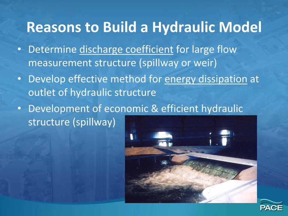
Reasons to Build a Hydraulic Model• Determine discharge coefficient for large flow
measurement structure (spillway or weir)
• Develop effective method for energy dissipation at outlet of hydraulic structure
• Development of economic & efficient hydraulic structure (spillway)
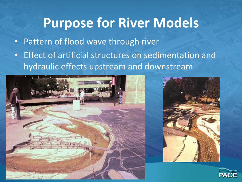
Purpose for River Models• Pattern of flood wave through river
• Effect of artificial structures on sedimentation and hydraulic effects upstream and downstream


Model vs. PrototypeHydraulic Model• Use principles of similitude to correlate model and
prototype behavior• Principle on which hydraulic model studies are based
comprises the theory of hydraulic similitude• Desired that the physical behavior of model simulate
that of the prototype• Dimensional analysis – basic relationship of the
physical quantities involved in the dynamic behaviors of water flow in a hydraulic structure

Principles of Similitude• Physical behavior of the model should simulate
in a know manner the behavior of the prototype– Can use data from the model can be used to predict
response of the prototype• Principles of similitude correlate model to
prototype behavior• Three basic types of similitude
1. Geometric similarity2. Kinematic similarity3. Dynamic similarity
• Forces dominate hydraulics for models require Dynamic Similarity

Principles of Similitude
• Geometric Similarity – all homologous dimensions on model and prototype are equal
• Kinematic Similarity – all homologous velocities and accelerations are equal between model and prototype
• Dynamic Similarity – all homologous forcesthe same between model and prototype
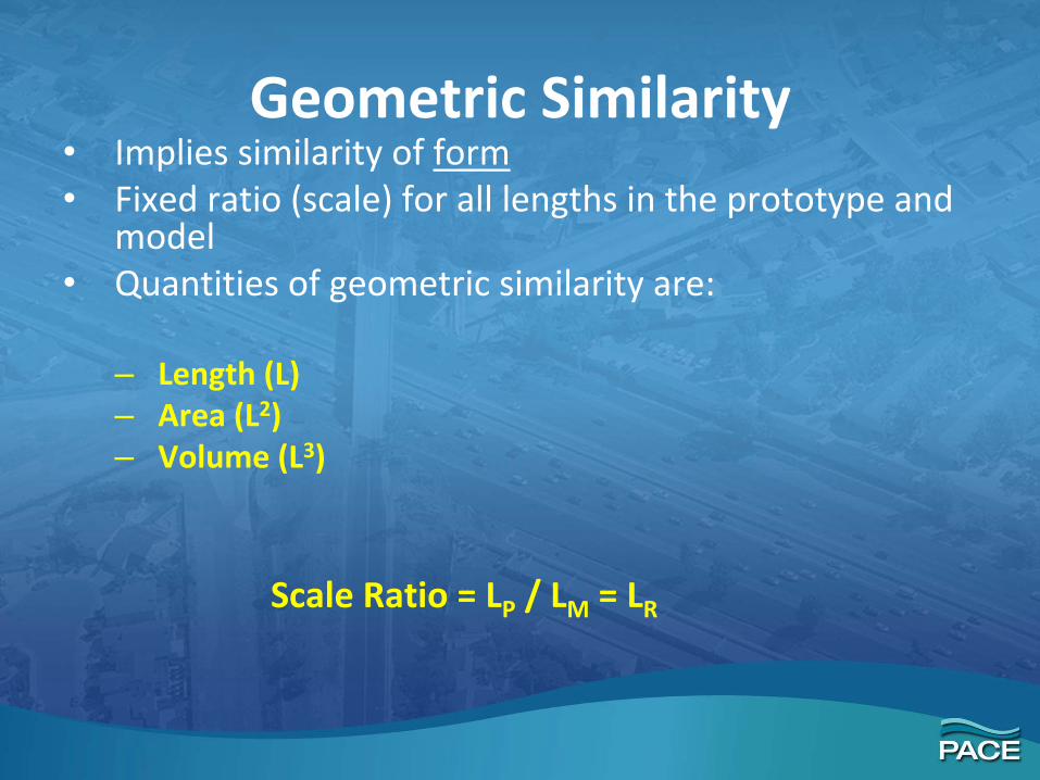
Geometric Similarity• Implies similarity of form• Fixed ratio (scale) for all lengths in the prototype and
model• Quantities of geometric similarity are:
– Length (L)– Area (L2)– Volume (L3)
Scale Ratio = LP / LM = LR

Geometric Similarity
Area
Volume
22
2
rM
P
M
P LLL
AA
==
33
3
3
3
rM
P
M
P LLL
VolVol
==

Kinematic Similarity• Implies similarity of motion• Involves time scale and length• Time ratio (Tr )for homologous particles to travel
homologous distance in model and prototype
• Time
• Velocity
rP
m TTT
=
r
r
M
M
P
P
M
P
TL
TLTL
VV
==

Kinematic Similarity
2
2
2
r
r
M
M
P
P
M
P
TL
TLTL
aa
==Acceleration
Discharge
r
r
M
M
P
P
M
P
TL
TLTL
QQ 3
3
3
==

Dynamic Similarity• Implies similarity of forces in motion• Force ratio (Fr )for homologous forces in model
and prototype is constant
• Force
• Dynamic Similarity requires and implieskinematic similarity and geometric similarity
• Must evaluate forces of (1) inertia, (2) pressure, (3) gravity, (4) viscosity, (5) surface tension, (6) elasticity
M
Pr F
FF =

Dynamic Similarity• Force is mass time acceleration and mass is
density time volume:
• Work
24 −=== rrrMMM
PPP
MM
ppr TL
aVolaVol
aMaM
F ρρρ
rrMM
PP
M
P LFLFLF
WW
==
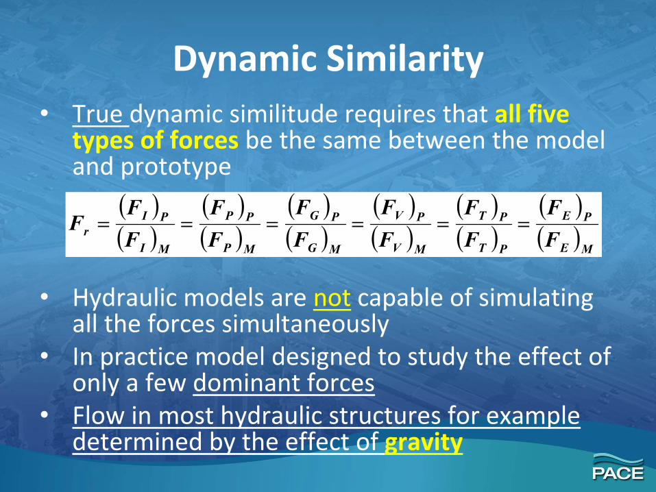
Dynamic Similarity• True dynamic similitude requires that all five
types of forces be the same between the model and prototype
• Hydraulic models are not capable of simulating all the forces simultaneously
• In practice model designed to study the effect of only a few dominant forces
• Flow in most hydraulic structures for example determined by the effect of gravity
( )( )
( )( )
( )( )
( )( )
( )( )
( )( )ME
PE
PT
PT
MV
PV
MG
PG
MP
PP
MI
PIr F
FFF
FF
FF
FF
FF
F ======
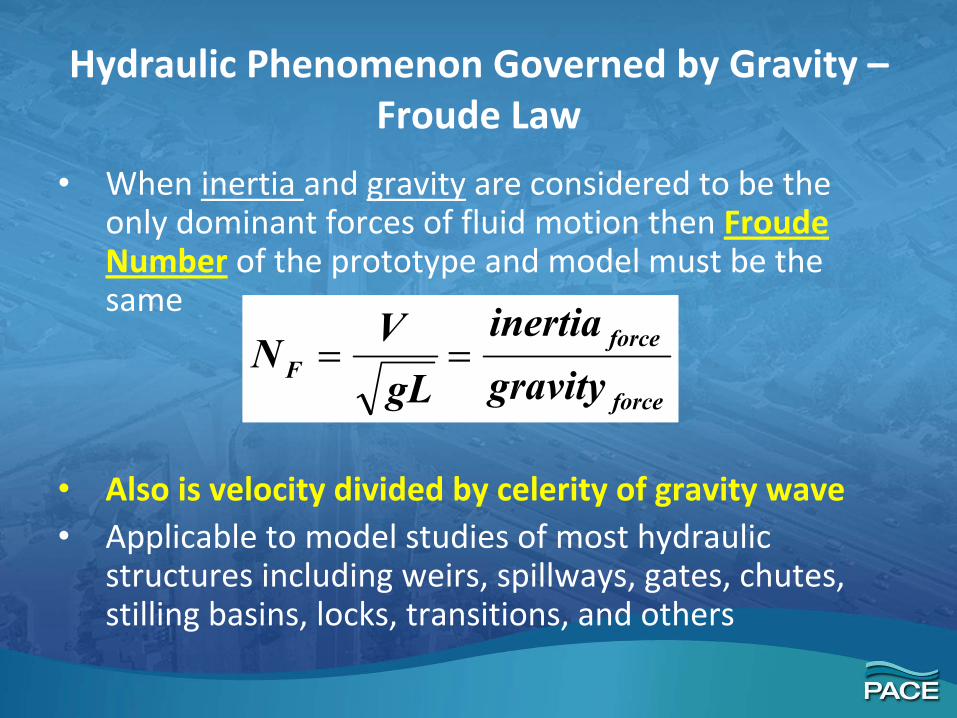
Hydraulic Phenomenon Governed by Gravity –Froude Law
• When inertia and gravity are considered to be the only dominant forces of fluid motion then Froude Number of the prototype and model must be the same
• Also is velocity divided by celerity of gravity wave• Applicable to model studies of most hydraulic
structures including weirs, spillways, gates, chutes, stilling basins, locks, transitions, and others
force
forceF gravity
inertiagLVN ==
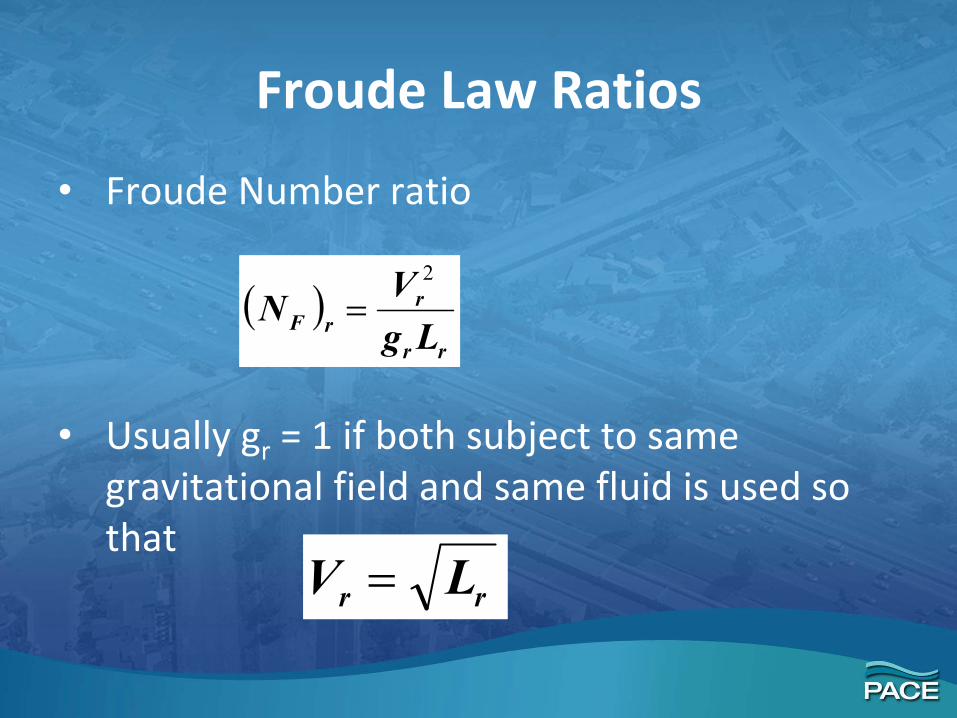
Froude Law Ratios
• Froude Number ratio
• Usually gr = 1 if both subject to same gravitational field and same fluid is used so that
( )rr
rrF Lg
VN2
=
rr LV =

Froude Law Ratios• Discharge Qr = Ar Vr = Lr
5/2
• Pressure Pr = γr Lr = Lr if same fluids
• Force Fr = γr (Volume)r = Lr3
• Energy Er = Fr Lr = Lr4
• Power Pr = Er Tr = Lr5/2
• Momentum Mr = mr Vr =ρr (Volume)r Lr1/2 = Lr
7/2
• Time Tr = Lr / Vr = Lr1/2

Hydraulic Phenomenon Governed by Viscosity – Reynolds Number Law
HYDRAULIC SIMILITUDE
• Fully enclosed flow (ie. pipe) gravity and surface tension have no effect
• Viscosity alone will control velocity and pressure from friction with inelastic flow
• Reynolds Number (NR) must be equal in model and prototype
force
forceR viscous
inertiaN =
µρLVNR =

Hydraulic Phenomenon Governed by Viscosity – Reynolds Number Law
• Important application of Reynolds Law is study of drag forces on immersed objects (ie. ships)
• Difficulties are encountered with Reynolds Law model studies if the number is high– Velocity ratio is inversely proportional to the
length ratio, model velocities have to be high
– Requires a wind tunnel with air as fluid

Reynolds Law Ratios• Velocity Vr = νr /Lr = 1/ Lr if same fluids
• Discharge Qr = Ar Vr = Lr2 νr /Lr = νr Lr = Lr
• Pressure Pr = 1/ Lr2 if same fluids
• Force Fr = 1.0
• Energy Er = Fr Lr = Lr
• Power Pr = Er Tr = 1/ Lr
• Momentum Mr = mr Vr =ρr (Volume)r νr /Lr=µr Lr2
• Time Tr = Lr / Vr = νr Lr2 = Lr
2

Model Studies With Both Gravity and Viscous Forces
• Example of this case– Open Channel on mild slopes
– Surface vessels moving through water
– Shallow water waves in open channels
• Both Froude number and Reynolds number
RF NN =
( ) 21 /rr
r
r
rrr
LgVVL
=µ
ρ

Model Studies With Both Gravity and Viscous Forces
• Simplifies to
• Almost impossible to meet requirement since special model fluid with kinematic viscosity ratio– For example a 1:10 scale model requires model fluid
with kinmeatic viscosity 30 times less than water• Solution for ship resistance, the model is based
on Reynolds law and operates in towing tank by Froude Law
23/rr L=ν

Open Channel ModelsFixed Bed
• Fixed Bed Study is distinguished from Moveable Bed Study
• Channel models are concerned with velocity and slope patterns so effect of bed roughness is very important
• Empirical hydraulic relation Manning equation used for similarity between model and prototype
( )r
rrr
r
rr
m
pr n
LyRnSR
VV
V21322132 //// /
===
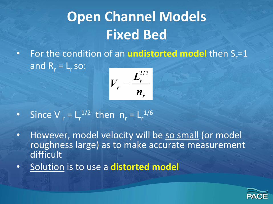
Open Channel ModelsFixed Bed
• For the condition of an undistorted model then Sr=1and Rr = Lr so:
• Since V r = Lr1/2 then nr = Lr
1/6
• However, model velocity will be so small (or model roughness large) as to make accurate measurement difficult
• Solution is to use a distorted model
r
rr n
LV32 /
=

Open Channel ModelsDistorted Model
• Distorted model where the vertical scale and horizontal scale ratios do not have same value
• Choose smaller vertical scale ratio or Xr > Yr
• Means model Slope greater than prototype
• Case 1 – Roughness values known for model and prototype then the distortion calculated from:
34
2
/r
rr
r
rr R
ynLy
S ==

Open Channel ModelsDistorted Model
Case 2 –Distortion ratio is fixed based on space considerations then model roughness calculated from:
• Means model roughness must be adjusted by trial and error until required flowrateobtained
21
32
21
3421
/
/
/
//
r
r
r
rrr L
RLRSn ==
23 /rrrrrrrrrr VVVLVyLVAQ ====

Model Design ‐ General
• Model required when established design procedures and available technical information fails to provide solution to hydraulic problems
• Hydraulic problems should be thoroughly examined• Define the accuracy of results from model• First and most important step is to select scale• For maximum similarity model should be large as
possible• Large model improves accuracy of measurements and
results– Difficulty in operation and costs

Open Channel Model Scale Selection • Channel model scales typically range from 1:15
to 1:70
• Scale depends on the following– Type of problem
– Relative roughness between model and prototype
– Size of prototype
• Scale ratios of 1:15 to 1:30 for supercritical wave patterns and outlet works having gates or valves
• Same scale used for “sectional models” of drop structures, spillways

Open Channel Model Scale Selection
• Canal structures, such as chutes and drops have scales ratios 1:3 to 1:20
• Smaller ratios 1:30 to 1:70 are used for general model studies of “long channels”
• River model scale ratios 1:100 to 1:1000
• Vertical scale for distorted river models ratios 1:20 to 1:100

Open Channel Model Scale Selection
• Flow measurements may control scale selection
• Most models of channel are generally built to give depths of flow about 0.5 feet
• Channel widths of 1 to 2 feet
• Common scales used the Los Angeles ACOE District Hydraulic Laboratory are 1:25 to 1:40

CHANNEL MODELS

CHANNEL MODELS
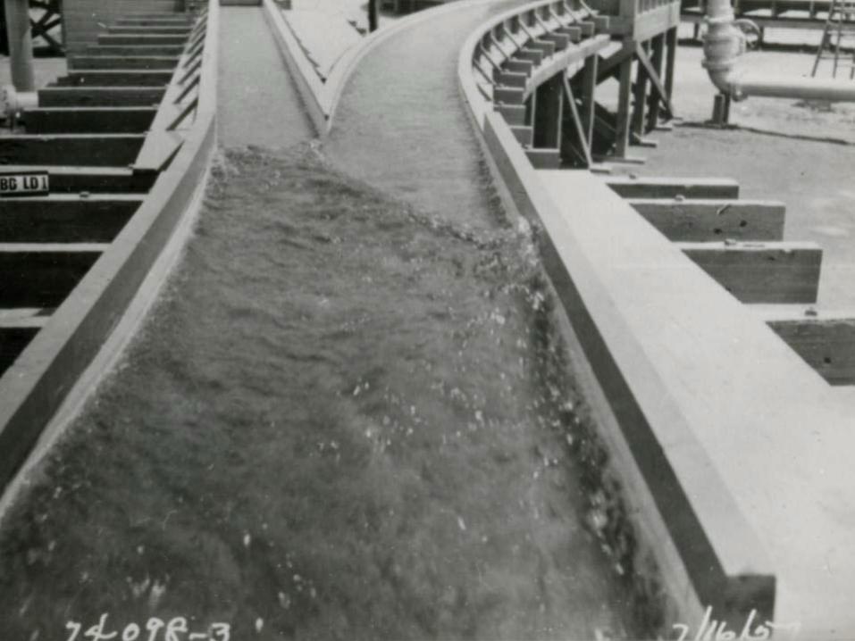
CHANNEL MODELS
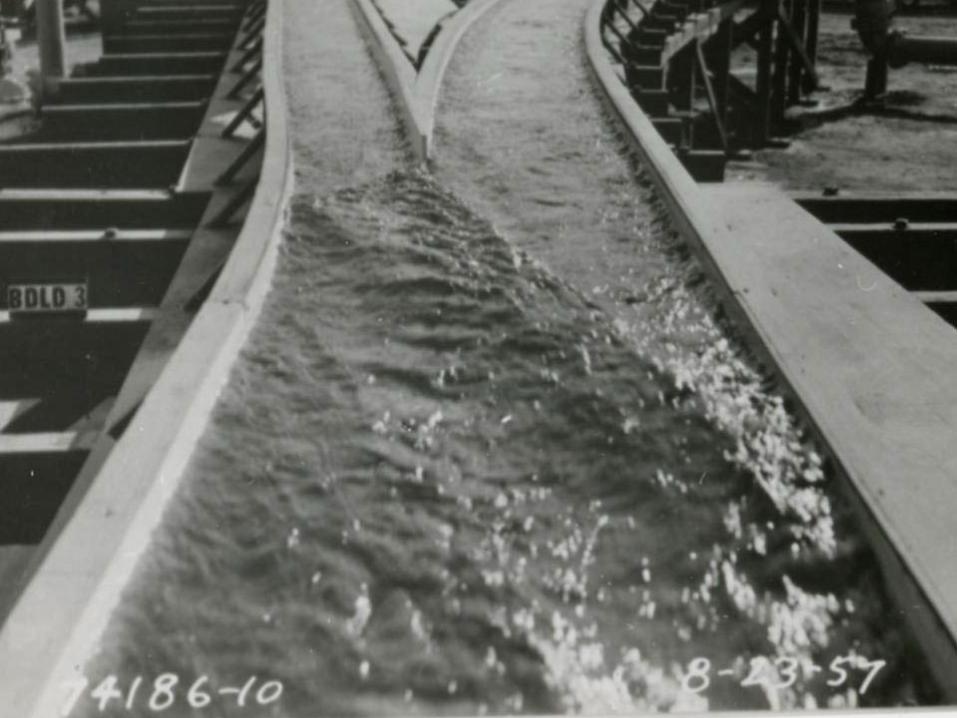
CHANNEL MODELS

CHANNEL MODELS
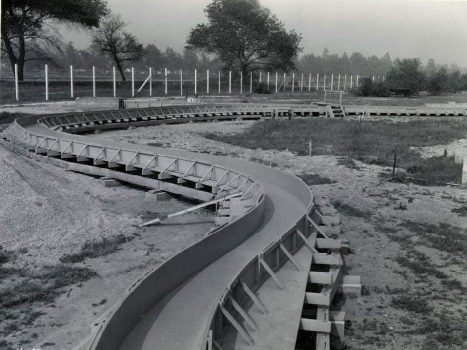
CHANNEL MODELS

CHANNEL MODELS

CHANNEL MODELS

CHANNEL MODELS


Model Study Centered on I‐405 Culvert System
Physical Model Study Reach = 1000 ft
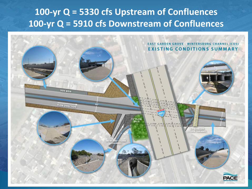
100‐yr Q = 5330 cfs Upstream of Confluences100‐yr Q = 5910 cfs Downstream of Confluences

Limitations of Computer Modeling
• Unequal lengths, slopes & geometries of the C05 culverts
• Assumption of uniform flow distribution across channel section
Limitations of Computer Modeling
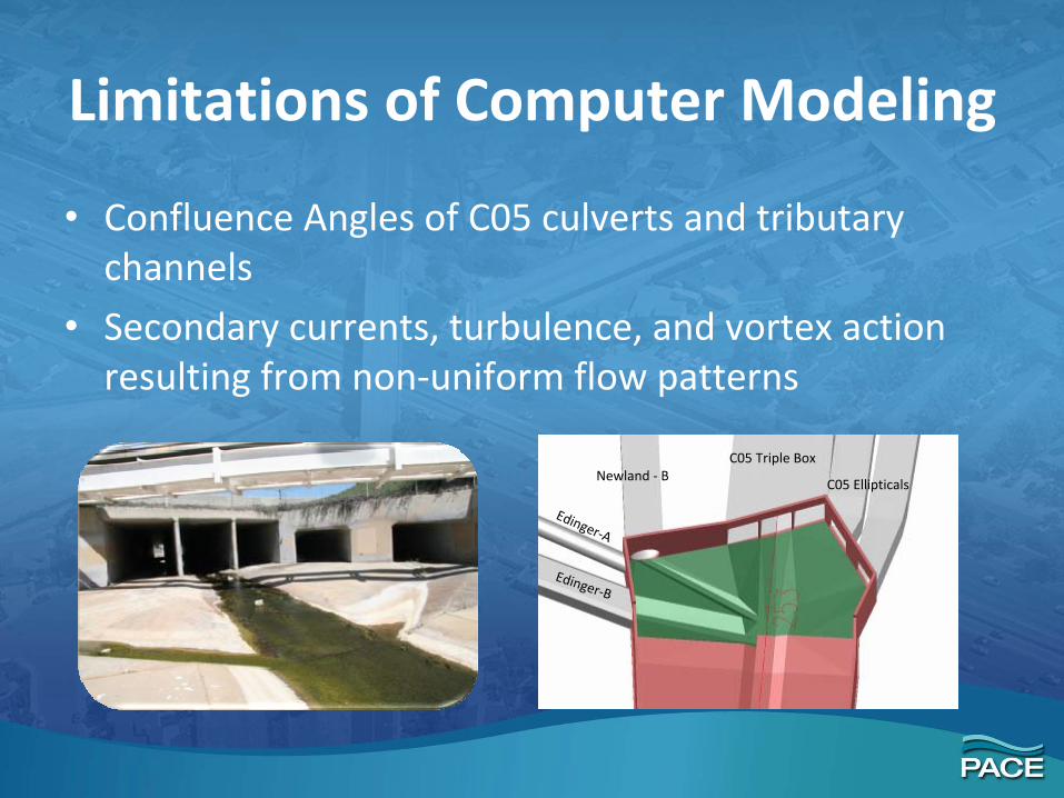
• Confluence Angles of C05 culverts and tributary channels
• Secondary currents, turbulence, and vortex action resulting from non‐uniform flow patterns
Edinger‐B
Newland ‐ BC05 Triple Box
C05 Ellipticals
Edinger‐A
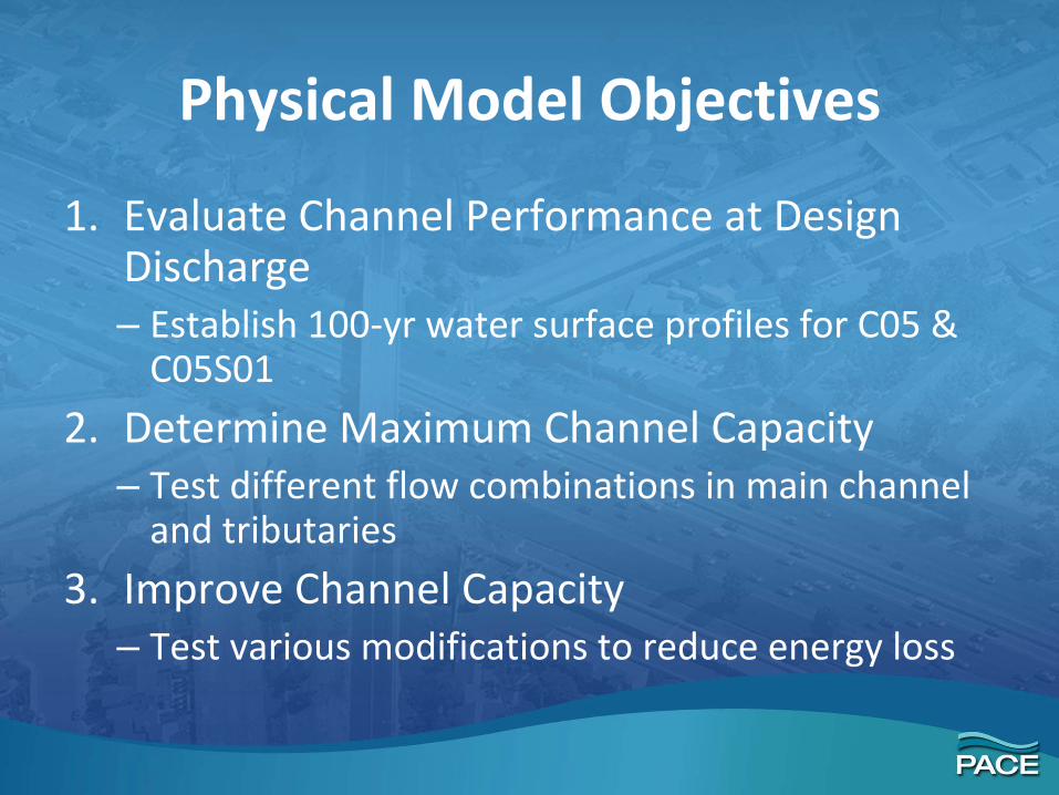
Physical Model Objectives
1. Evaluate Channel Performance at Design Discharge– Establish 100‐yr water surface profiles for C05 &
C05S01
2. Determine Maximum Channel Capacity– Test different flow combinations in main channel
and tributaries
3. Improve Channel Capacity– Test various modifications to reduce energy loss

Physical Model Design• 3D CAD Model channel
designed using as‐builts and proposed improvement drawings for Newland & Edinger facilities

15:1 Scale Selection Driven by Project Budget
• Measurement accuracy (allowable error) – small scaled error can become large prototype error
• Channel roughness (material selection)– Scaled mannings roughness value for concrete = 0.0089
• Available Warehouse Space

Hydraulic Properties of 15:1 Scale Model
• Model hydraulics influenced by inertial and gravitational forces
• Scale to prototype relationships, hydraulic similitude, based on Froude Number Law

Hydraulic Model Structure
• Model Channel elevated on adjustable platform
• Storage reservoir below provides conveyance and submergence over pump intakes
• Head tank dissipates flow energy before entering channel

Pump System designed for Max Efficiency and Flexibility
Horizontal Pump Dimensions:
15 Horsepower, 3 Phase
1200 gpm at 15’ of Head
Weight = 156 lbs
Height, A = 12.875”
Min Submergence, B = 30”
Discharge Diameter, D = 6” NPT
Pump Length, E = 24.625”
Pump Width, F = 16”
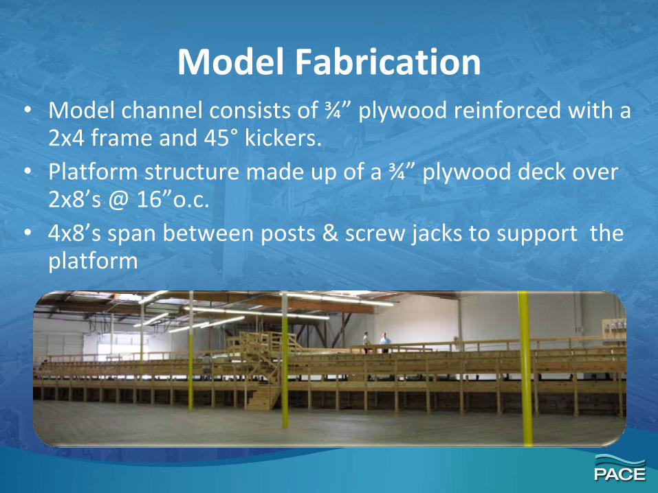
Model Fabrication• Model channel consists of ¾” plywood reinforced with a
2x4 frame and 45° kickers. • Platform structure made up of a ¾” plywood deck over
2x8’s @ 16”o.c.• 4x8’s span between posts & screw jacks to support the
platform

Model Channel was Waterproofed using a lot of Silicone and a Multi‐coat Waterproof Paint

Low Flow Channels Upstream and Downstream of I‐405 Culverts were Formed with Concrete

Model Channel Fabricated to a Tolerance of 0.002 ft
• Screw Jacks placed along both sides of flume allow for vertical adjustment
• Final adjustments made with the help of a surveyor using a total station

Dual Function Storage Reservoir
• Provides required submergence depth for pumps to operate
• Convey flow from tail box to pumps
• Captures leakage from model channel
• Waterproofed using seam welded PVC liner

Head Tanks Designed to Hold 8 ft of Water
• Structural 2x lumber used to form ribs
• Lined with 1” plywood and coated with waterproof paint
• Hanging baffles dissipate flow energy from pumps

Scaled Culvert Geometry Presents a Unique Challenge
• Scaled dimensions of elliptical culvert are 5.13”x 8.07”
• Fabricated using CNC technology to create foam molds
• Fiberglass formed around molds to correct dimensions

CNC Technology allowed for fabrication of unique culvert geometry
Complex transitions from rectangular to elliptical in a curved alignment occur at entrance and exit of each C05 elliptical
culvert
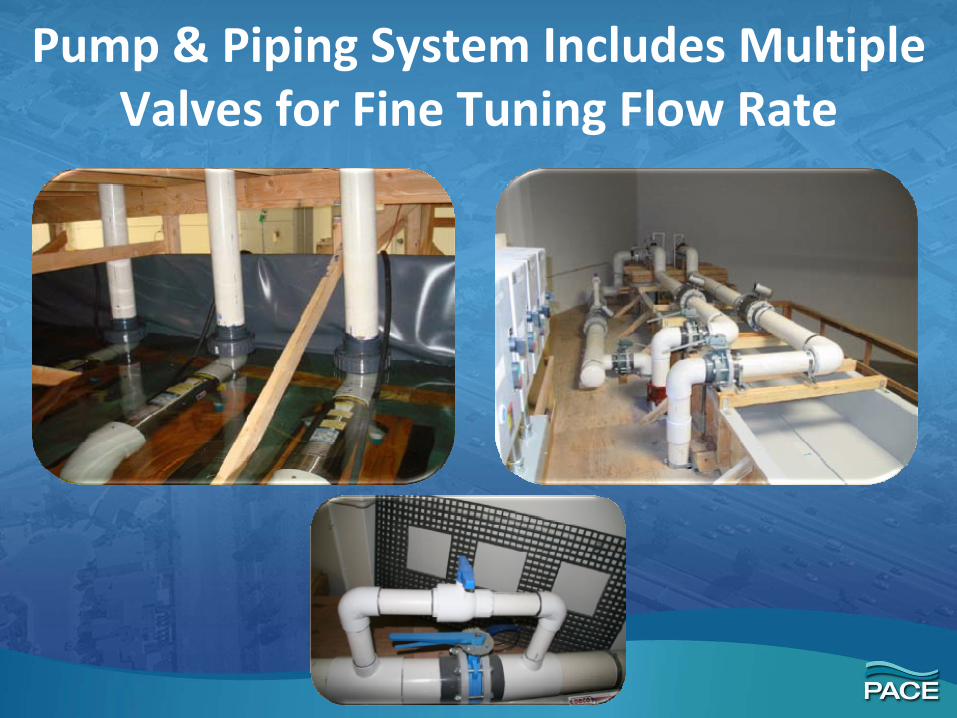
Pump & Piping System Includes Multiple Valves for Fine Tuning Flow Rate

Adjustable (Tail) Gate Provides Downstream Boundary Control

Model vs Prototype ComparisonUpstream of I‐405

Model vs Prototype ComparisonDownstream of I‐405

Model vs Prototype ComparisonNewland Channel

Model Calibration – Surface Roughness
• Initial tests will be conducted to verify channel roughness values
• Point gages will be used to measure flow depth to the nearest 0.1 mm (0.0003’)

Model Calibration –Flow Meter Readings
• Sharp crested weirs will be used to calibrate the Ultrasonic flow meter readings
• V‐notch weir will be used for flows up to 1,000 gpm
• Rectangular weir used for flows up to 3,000 gpm
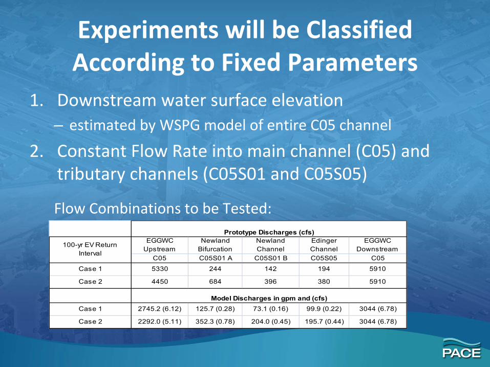
Experiments will be Classified According to Fixed Parameters
1. Downstream water surface elevation– estimated by WSPG model of entire C05 channel
2. Constant Flow Rate into main channel (C05) and tributary channels (C05S01 and C05S05)
EGGWC Upstream
Newland Bifurcation
Newland Channel
Edinger Channel
EGGWC Downstream
C05 C05S01 A C05S01 B C05S05 C05
Case 1 5330 244 142 194 5910
Case 2 4450 684 396 380 5910
Case 1 2745.2 (6.12) 125.7 (0.28) 73.1 (0.16) 99.9 (0.22) 3044 (6.78)
Case 2 2292.0 (5.11) 352.3 (0.78) 204.0 (0.45) 195.7 (0.44) 3044 (6.78)
Model Discharges in gpm and (cfs)
100-yr EV Return Interval
Prototype Discharges (cfs)
Flow Combinations to be Tested:

Additional Tests will Evaluate Options for Improving Channel Performance
Adjustments to size and angle of Newland Channel confluence
Splitter walls, pier noses or other ways to reduce energy loss