Embed Size (px)
Citation preview

1
Real Time Visualization, Topology Processing and Simulation
- PowerWorld Retriever Implementation at ISO-NE
Wednesday, June 14, 2006
Xiaochuan Luo, Yujie Hu
Presentation Title© 2005 ISO New England Inc. 2
Drivers of the ISO NE Retriever Project• Develop advanced Power System visualization tools as
a result of the 2003 Blackout and for the new ISO NE Control Room Wallboard
• Provide IT/EMS with additional Modeling and Analysis capabilities
• Provide operations and planning a platform to analyze the EMS case, taking advantage of the the advanced analyzing capability such as ATC, PV/QV, etc
• Cyber Security - PowerWorld Retriever/Simulator does not require EMS WebFG access thus improved EMS cyber security through fewer EMS users

2
Presentation Title© 2005 ISO New England Inc. 3
ISO NE Retriever Project: Visualization
• Wallboard one-line display
• GIS based contours (Nodal LMP, Voltage)
• Bubble diagram of internal interface monitor
• Bubble diagram of wide area monitor
• Generator Mvar reserve monitor
Presentation Title© 2005 ISO New England Inc. 4
ISO NE Retriever Project: Simulation
• Automatic, real-time EMS network model synchronization with PowerWorld (model AUX, contingency AUX, SPS AUX)
• Retrieve historical EMS case via PI system and solve power flow (post mortem analysis)
• Validation of EMS Network modeling

3
Presentation Title© 2005 ISO New England Inc. 5
EMSSCADA, AGC,
Network Model, State Estimation/CA,
PowerFlow
PI SystemBHE
ME
S-ME
NH
VT
HQ
C-MA Boston
SEMARI
CT
SWCT
NOR
NY
NB
NEMA
CSC
W-MA
Orrington-South
Suroweic-South
ME-NH
NB-NE
NE-NY
Norwalk-Stamford SWCT Import CT Import
SEMA/RI Southeast MASS
Boston Import
North-South
Highgate
Phase II
West-East
New England Interface Bubble Diagram
0 MW1800 MW
0 MW89999 MW
0 MW1035 MW
0 MW1395 MW
0 MW1460 MW
0 MW89999 MW
0 MW89999 MW
0 MW1628 MW
0 MW1229 MW
0 MW 710 MW
0 MW 838 MW
0 MW2972 MW
0 MW 0 MW
0 MW
0 MW 0 MW
0 MW
0 MW
0 MW
0 MW
0 MW
0 MW
0 MW
0 MW
0 MW
0 MW
0 MW
0 MW
0 MW
0 MW
0 MW1875 MW
0 MW
0 MW
Read-OnlyShare
RTNET/RTCA /PWRFLOW savecases
Real-Time & Archived Data
Data Retrieval Layer Analysis & Visualization LayerEMS Layer
PowerWorld EMS Integration
Market DatabaseLMP's, SCED solutions,
etc
PW Simulator
PW Retriever
Presentation Title© 2005 ISO New England Inc. 6
EMS Real Time Case Export
• Data Retrieval Layer
– ISO EMS has been modified to :Automatically export real-time state estimation model
– model_rtnet_autorun_rtnet_ems.auxAutomatically export Contingency and SPS definitions
– ctgs_rtca_autorun_rtca_ems.aux– auto_load_sps_definitions.aux
– All exports are pushed to a share on the sever such that any PW user in the company can access current EMS case without requiring EMS environment

4
Presentation Title© 2005 ISO New England Inc. 7
EMS Study Case Export
• EMS Power Flow and Contingency Analysis users can export their study cases to PowerWorld in ~10 seconds
• Three EMS applications to export PowerWorld cases
– EMS PWRFLOW Application (model aux file only)
– EMS STCA Application (model aux, contingency aux)
– EMS PWRWORLD Application (model aux, contingency aux, real time subscription aux)
Presentation Title© 2005 ISO New England Inc. 13
ISO New England EMS Model to PowerWorld
• Sub: SubNum, SubName, Latitude, Longitude• Bus: BusNum, BusName, BusNomVolt, Area, Zone, SubNum,
Latitude, Longitude, BusKVVolt, BusAngle, LSName, BusMonEle, BusVoltLimHigh, BusVoltLimLow
• Area: AreaNum, AreaName, BGAGC • Zone: ZoneNum, ZoneName• Load: MW, Mvar• Shunt: SSRegNum, DesiredVoltage,SSCmode,SSVHigh,
SSVLow,SSNMVR,SSBlockNumSteps, SSBlockMVarPerStep
• Gen: MW, Mvar, VoltSet, GenRegNum, AGC, AVR, MWMin, MWMax, MVRmin,MVRmax, UseCapCurve, GenParFac, GenRMPCT
Node-Breaker model:

5
Presentation Title© 2005 ISO New England Inc. 14
ISO New England EMS Model to PowerWorld
• Branch• Line: BusNum, BusNum:1, R, X, C, LineMonEle, LSName,
LineAMVA, LineAMVA:1, LineAMVA:2• Transformer: All transformer base parameters • Phase Shifter• ZBR• Breaker
• Transformer Impedance Correction table• Interface Definition• Study MW Transaction• Injection group
• Generation Dispatch Zone• Load Tree Structure
• EMS Solution parameters, including solution tolerances
Presentation Title© 2005 ISO New England Inc. 15
Implementation of Retriever Visualization
• Three Phases:
• Phase I: Sample displays built based on planning model and connection to PI to promote the visualization project (end of 2004 to early 2005)
• Phase II: Synchronize Retriever with EMS model and robust connectivity with real-time PI System; Developed four prototyped displays to control room and several others within the company (March 2005 - July 2005)
• Phase III: Large scale wallboard displays (December 2005 – May 2006)

6
Presentation Title© 2005 ISO New England Inc. 16
Implementation of Retriever Visualization
• Prototype wallboard (9X3 array, 20” LCD monitors)• Hired a professional A/V company to help optimizing the
content of wallboard displays and develop a style guide• Daily interaction with control room operators when
building displays• Testing was actually done by control room operators• All employee move to new building on April 24, 2006• Parallel control room operation between May 1 and 5• Final control room move on May 5, 2006 and Wallboard
(9X3 array, 80” DLP video wall) go live !• Operators love it!
Presentation Title© 2005 ISO New England Inc. 17
Wallboard: 9*3 array, 12 feet tall, 48 feet wide

7
Presentation Title© 2005 ISO New England Inc. 18
Wallboard: 9*3 array, 12 feet tall, 48 feet wide
Presentation Title© 2005 ISO New England Inc. 19
Substation One Line Diagram

8
Presentation Title© 2005 ISO New England Inc. 20
Voltage Contour
Presentation Title© 2005 ISO New England Inc. 21
Nodal LMP Contour

9
Presentation Title© 2005 ISO New England Inc. 22
ISO NE Internal Interface Bubble
Presentation Title© 2005 ISO New England Inc. 23
Wide Area Monitor
10
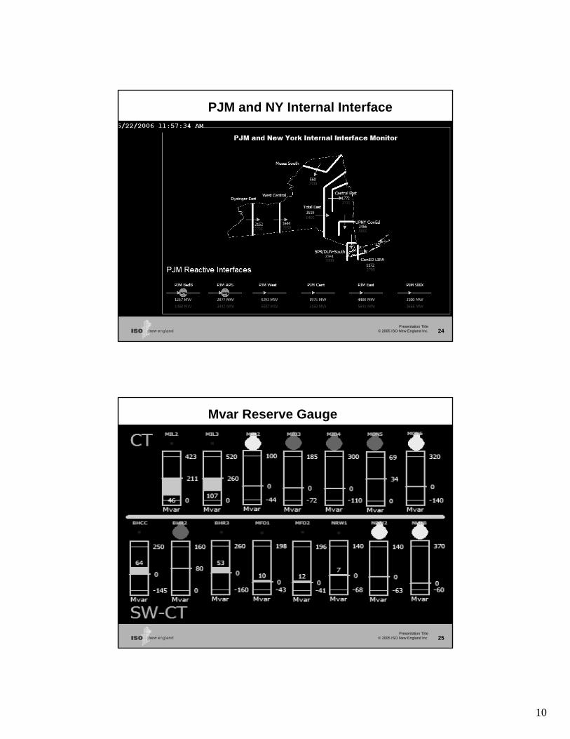
Presentation Title© 2005 ISO New England Inc. 24
PJM and NY Internal Interface
Presentation Title© 2005 ISO New England Inc. 25
Mvar Reserve Gauge

11
Presentation Title© 2005 ISO New England Inc. 26
Future Displays
• 3D Mvar Reserve Monitor
• Island Display, using island number either from
• EMS, or
• Topology Processing feature of Retriever 12
• Advanced displays per operators’ request
Presentation Title© 2005 ISO New England Inc. 27
Topology Processing and
Real Time Power Flow

12
Presentation Title© 2005 ISO New England Inc. 28
Topology Processing
• Besides allowing effective visualization of real-time data, Retriever can be set up to obtain power flow solutions.
• The solution requires handling and interacting with two different representations of the power system:
– Node/Breaker or Full (Topology) model,– Bus/Branch or Consolidated model
• Power flow and state estimator algorithms use the Bus/Branch model
• Topology Processing algorithm is used to convert the Node/Breaker model into a Bus/Branch model
Presentation Title© 2005 ISO New England Inc. 29
Solving the Consolidated Model
• Consolidating a model has two advantages:– It prevents numeric instability by removing low-
impedance branches from the power flow Jacobian– It solves a much smaller case, which is particularly
important in contingency analysis • Once the consolidated model is solved, the results can be
mapped to the full model– Bus voltages are mapped back to all the related
nodes • Save consolidated case as PWB, PSSE, PSLF, IEEE, etc• The case can be shared with other workgroups such as
planners and market participants

13
Presentation Title© 2005 ISO New England Inc. 30
Demo of Topology Processing using ISO New England EMS case
• Open a case in Full topology
• Case Information --- Buses to show nodes under full topology
• Topology Processing Dialog
• Init new case (show log)
• Run TP (show log)
• Case Information – Buses to show buses under consolidated model
• Solve consolidated case
• Save the case to *.pwb or other format
Presentation Title© 2005 ISO New England Inc. 31
Contingency Analysis
• Contingency actions may involve breakers that were already merged
• Two methods to model actions in the contingency analysis:– Keep in the consolidated case all the switching
devices that are involved in contingency actions.– Dynamically restore portions of the full model to the
consolidated system.
• Retriever currently uses the first method

14
Presentation Title© 2005 ISO New England Inc. 32
Demo of Real Time Contingency Analysis
• Load the model AUX and contingency AUX files
• Show contingency under full topology
• Open TP dialog and select “Preserve all Breakers involved in Active Contingencies”
• Show bus information of consolidated model
• Show contingency definition of consolidated model
• Press the Start Run button in the Consolidated Contingency Analysis
Presentation Title© 2005 ISO New England Inc. 33
Real Time Retrieving and Power Flow
Data Source:
• Visualization: SCADA
• PowerFlow: RTNET
• Redundant PI Server
Mode:
Visualization: Real Time Power Flow: RUN

15
Presentation Title© 2005 ISO New England Inc. 34
Real Time Power Flow Retrieve real time data
Topology mapping for visualization
Populate RT data to UPF
Consolidate with TP
Solve Consolidated PF
Map results back to full model
Presentation Title© 2005 ISO New England Inc. 35
Real Time Retrieving and Power Flow
Tells Retriever to automatically perform the actions indicated by checked boxes after data Retrieval.
Tells the status of automatic power flow solution.
Each action can take place only if the previous box is checked.
Map the consolidated power flow solution to the full model after the solution is obtained.

16
Presentation Title© 2005 ISO New England Inc. 36
Demo of Real Time Power Flow
Use ISO New England real time case and data source todemo the real time power flow solution
Presentation Title© 2005 ISO New England Inc. 37
Summary
• PowerWorld Retriever implemented at ISO-NE to retrieve and visualize real-time power system data via the ISO PI System.
• Automatic, real-time EMS network model synchronization with PowerWorld has been developed, tested and deployed
• PowerWorld Power Flow and Contingency Analysis functions have been tested and correlate accurately with online ISO EMS solutions
• Retrieve historical data through PI system, generate the case and obtain power flow solution for further analysis