Embed Size (px)
Citation preview

READ AND SAVE THESE INSTRUCTIONS
Utility Distribution SystemInstallation, Operation and Maintenance Manual
GREENHECKKITCHEN VENTILATION SYSTEMS
SCHOFIELD, WISCONSIN 54476-0410PH. 715-359-6171 www.greenheck.com¨
Warning!!Improper installation, adjustment, alteration, service or maintenance can causeproperty damage, injury or death. Read the installation, operating, and maintenanceinstructions thoroughly before installing or servicing this equipment.
This manual is the property of the owner, and is required for future maintenance.Please leave it with the owner when you complete the job.
Receiving and HandlingUpon receiving the equipment, check for both obvious and hidden damage. If damageis found, record all necessary information on the bill of lading and file a claim with thefinal carrier. Check to be sure that all parts of the shipment, including accessories, areaccounted for.

GREENHECK¨October 1999
2
Table of Contents
Installation Page
Wall System Model GUW ............................................................................................3
Island System Model GUI ............................................................................................4
Electrical Connections ..................................................................................................5
Electrical Fire Fuel Connections ..................................................................................6
Plumbing Connections ................................................................................................7
Hose Assemblies Installation ......................................................................................8
Operating Instructions
Ground Fault Connection Plate ....................................................................................9
Power Sensitive Ground Fault Relay ..........................................................................10
Fire Fuel Shut Off ..........................................................................................................11
Gas 5 Second Delay ....................................................................................................11
Remote Status Indicator Lights ..................................................................................11
Ventilator Light Switch..................................................................................................11
Exhaust Motor Fan Motor Controls ............................................................................12
Emergency Stop ..........................................................................................................12
General Plumbing Instructions ....................................................................................13
This manual will acquaint you with the operation and proper maintenance of yourUtility Distribution System. IT IS IMPORTANT THAT YOU READ THIS MANUALTHOROUGHLY AND FOLLOW ITS RECOMMENDATIONS.In certain instances the manual make reference to features which may or may notbe part of your equipment. To determine whether such references apply to you,please consult your submittal and electrical drawings which have been prepared foryou as part of this manual.

GREENHECK¨ October 1999
3
UTILITY DISTRIBUTION SYSTEM
Model GUW InstallationA. WALL MOUNTED:
1. Read entire manual and study drawings before starting installation.
2. Check that all electrical and plumbing rough-ins are as specified and agree with the drawing.
3. The GUW system consists of the following parts:
a. Riser
b. Raceway
c. Pedestal (optional)
4. Remove all access panels on raceway, riser and pedestal to reveal internal plumbing, electrical systems, and internalflanges.
5. Place GUW sections according to the drawing to determinethe proper mounting positions.
6. Once sections are in position, join field joints (if any) by bolting internal flanges together and applying NSFapproved silicone caulk (GE SCS-1009, or its equivalent ) over seams. Caulk is not provided.
7. GUW mounting procedures:
a. Mount stainless steel channel (shipped loose) in proper location on wall.
b. Place unit on channel and insert studs, on the unit, into the holes in the channel.
c. Drill holes through unit as shown on drawing and secure properly to wall.
8. If height of GUW interferes with perimeter of hood at time of installation, proceed as follows:
a. Remove pedestals
b. Slip riser up into hood
c. Reattach pedestals
9. Secure field joint support pedestal(s) to the floor as required, and seal the unit to the wall and floor with an NSF approved silicone caulk, (GE SCS-1009, or its equivalent). Caulk not provided.
Wall Mounted
GREENHECK¨October 1999
4
UTILITY DISTRIBUTION SYSTEM
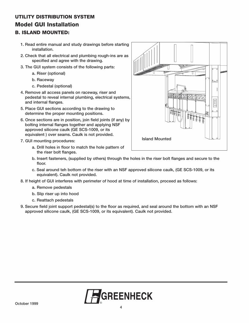
Model GUI InstallationB. ISLAND MOUNTED:
1. Read entire manual and study drawings before starting installation.
2. Check that all electrical and plumbing rough-ins are as specified and agree with the drawing.
3. The GUI system consists of the following parts:
a. Riser (optional)
b. Raceway
c. Pedestal (optional)
4. Remove all access panels on raceway, riser and pedestal to reveal internal plumbing, electrical systems,and internal flanges.
5. Place GUI sections according to the drawing to determine the proper mounting positions.
6. Once sections are in position, join field joints (if any) by bolting internal flanges together and applying NSFapproved silicone caulk (GE SCS-1009, or its equivalent ) over seams. Caulk is not provided.
7. GUI mounting procedures:
a. Drill holes in floor to match the hole pattern of the riser bolt flanges.
b. Insert fasteners, (supplied by others) through the holes in the riser bolt flanges and secure to the floor.
c. Seal around teh bottom of the riser with an NSF approved silicone caulk, (GE SCS-1009, or its equivalent). Caulk not provided.
8. If height of GUI interferes with perimeter of hood at time of installation, proceed as follows:
a. Remove pedestals
b. Slip riser up into hood
c. Reattach pedestals
9. Secure field joint support pedestal(s) to the floor as required, and seal around the bottom with an NSFapproved silicone caulk, (GE SCS-1009, or its equivalent). Caulk not provided.
Island Mounted
GREENHECK¨ October 1999
5
ELECTRICAL CONNECTIONS
Installation
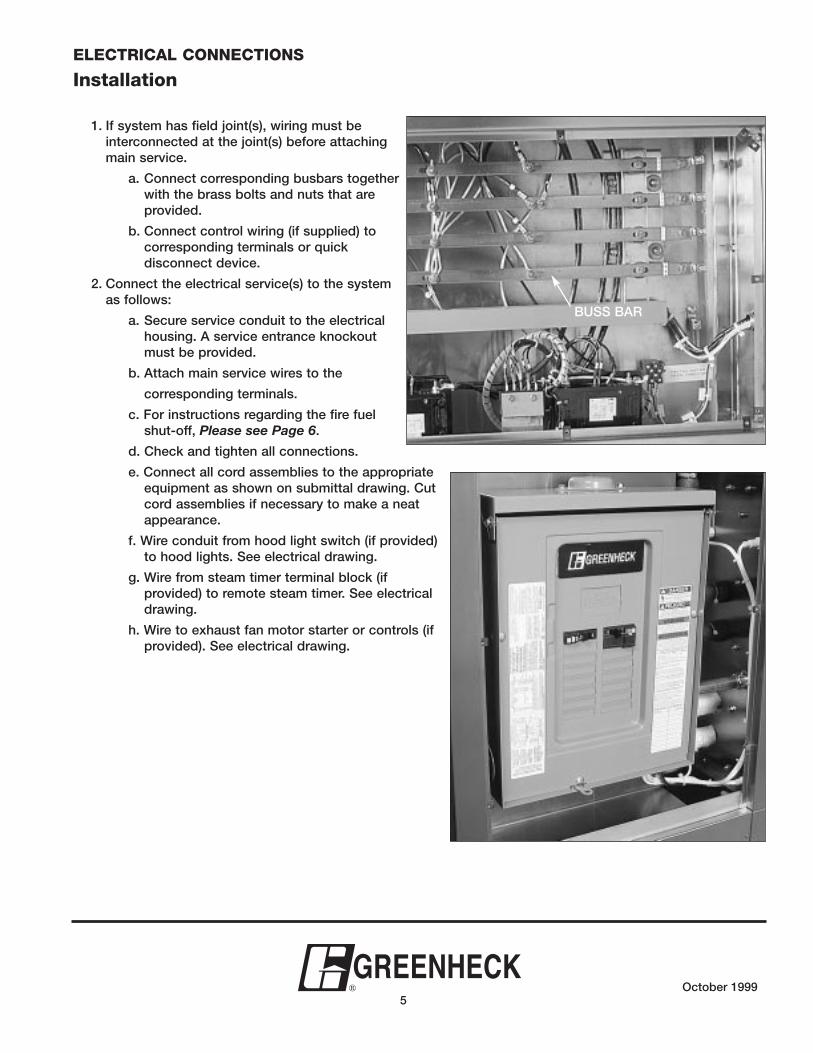
1. If system has field joint(s), wiring must be interconnected at the joint(s) before attaching main service.
a. Connect corresponding busbars together with the brass bolts and nuts that are provided.
b. Connect control wiring (if supplied) to corresponding terminals or quick disconnect device.
2. Connect the electrical service(s) to the system as follows:
a. Secure service conduit to the electrical housing. A service entrance knockout must be provided.
b. Attach main service wires to the
corresponding terminals.
c. For instructions regarding the fire fuel shut-off, Please see Page 6.
d. Check and tighten all connections.
e. Connect all cord assemblies to the appropriate equipment as shown on submittal drawing. Cut cord assemblies if necessary to make a neat appearance.
f. Wire conduit from hood light switch (if provided) to hood lights. See electrical drawing.
g. Wire from steam timer terminal block (if provided) to remote steam timer. See electrical drawing.
h. Wire to exhaust fan motor starter or controls (if provided). See electrical drawing.
BUSS BAR

GREENHECK¨October 1999
6
ELECTRICAL FIRE FUEL CONNECTIONS
Installation
1. Route three wires in 1/2" conduit (as shown on drawing) from the micro-switch in the fire control system (by others) to the equipment shut-off terminal block (red) in the Utility Distribution System. DO NOT remove any existing wires from terminals. Connect wires to the UNUSED posts of the labeled terminal block as follows:
a. Connect the neutral wire to the terminal labeled “N”.
b. Locate wire which supplies 120 volts during normal operating conditions (and is switched OFF whenfire control system is activated), and connect this wire to the empty terminal labeled “S1”.
c. Locate wire which is OFF during normal operating conditions (and applies 120 volts when fire control system is activated), and connect this wire to the terminal labeled “S2”.
N
120 VBLACK /S1
RED /S2
WHITE /N
TERMINALBLOCK
MICRO-SWITCH
FIRE-FUEL SHUT OFF FIELD WIRING
NOTE: DASHED LINE INDICATES ITEMS FURNISHED BY OTHERS

GREENHECK¨ October 1999
7
PLUMBING CONNECTIONS
Installation
1. If system has field joint(s), plumbing must be connected at the joint(s) before attaching main service. Connect corresponding pipes by aligning unions and tightening securely.
2. Connect all plumbing stub-ins to the main lines. Provide all necessary nipples, couplers, unions, etc. to make neat and proper connection.
3. Connect all hose assemblies to the appropriate equipment as shown on drawing. Provide all necessary ells and nipples to make neat and proper appearance. (Please see hose installationinstructions on Page 8.)
4. Check all plumbing for leaks and tighten as required.
5. Connect hood wash system (if provided) to spraynozzles in hood.
6. Replace all access panels.
This equipment is to be installed with adequate backflow protection to comply with federal, state or local codes having jurisdiction.
GREENHECK¨October 1999
8
HOSE ASSEMBLIES
Installation
1. Check sizes and quantity of hose assemblies as shown on submittal drawing.
2. Connect all hose assemblies to the appropriate equipment as shown on submittal drawing. Provide and install necessary plumbing fittings to present a neat appearance and to ensure that hose assemblies do not touch floor.
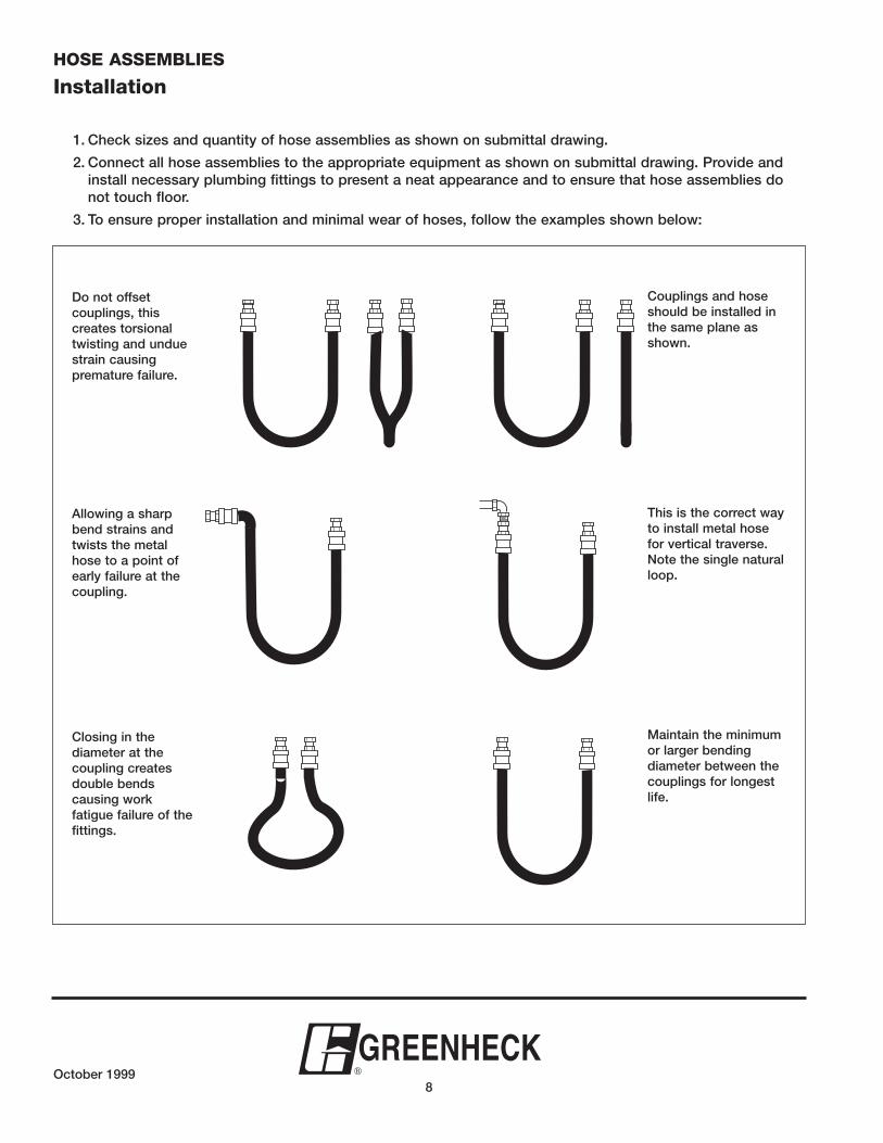
3. To ensure proper installation and minimal wear of hoses, follow the examples shown below:
Do not offset couplings, this creates torsionaltwisting and unduestrain causingpremature failure.
Allowing a sharpbend strains andtwists the metalhose to a point ofearly failure at thecoupling.
Closing in the diameter at the coupling createsdouble bends causing workfatigue failure of thefittings.
Couplings and hoseshould be installed inthe same plane asshown.
This is the correct wayto install metal hosefor vertical traverse.Note the single naturalloop.
Maintain the minimumor larger bendingdiameter between thecouplings for longestlife.

GREENHECK¨ October 1999
9
GROUND FAULT ELECTRICAL CONNECTION PLATE (OPTIONAL)
Operating Instructions
1. Turn all individual equipment controls to the OFF position before attempting to connect or disconnect any cord and plug assembly. After the cord and plug assembly is connected, equipment may be turned ON.
2. The Greenheck ground fault electrical connection plate consists of the following:
a. Point-of-use circuit breaker.
b. Power sensitive ground fault relay
c. Push to test button
d. Green LED
3. When the circuit breaker is in the OFF position, the LED is not illuminated. To energize the outlet, turn the circuit breaker to the ON position. The LED will turn on.
NOTE: Upon initial start-up, the circuit breakers may occasionally require a "break-in" procedure. Turn the circuit breakers OFF and ON several times.
4. To test the connection plate, turn the circuit breaker to the ON position and press the PUSH TO TEST button. The circuit breaker will automatically turn to the OFF position and the outlet will be de-energized.
5. Turn the circuit breaker back to the ON position and the outlet will be energized. The equipment is now ready for operation.
NOTE: Ground fault nuisance tripping may occur on certain pieces of equipment. If this situation occurs, follow these steps:
a. CAUTION -- Turn all main services to the raceway OFF.
b. Carefully remove the two screws securing the long access panel. Tilt the access panel down until the restraining chain holds the panel in the OPEN position.
c. Locate the Greenheck ground fault sensing relay and adjust the potentiometer slightly clockwise. Please see the diagram on Page 10.
d. Carefully replace the connection plate in the unit and tighten securely.
e. Repeat steps 3 and 4.
NOTE: If tripping continues, the piece of equipment which is connected to the plate assembly must be thor-oughly checked-out.
DESC. ____________
___V. ___PH. ___AMPSCONN. NO. _________
20 OF
F
ON
PUSH TO TEST
ITEM NO. ______ STATUS LIGHT
Circuit Breaker Ground FaultTest Button
Test lightVinyl Label

GREENHECK¨October 1999
10
POWER SENSITIVE GROUND FAULT RELAY
Ground FaultAdjustmentPotentiometer

GREENHECK¨ October 1999
11
FIRE FUEL SHUT-OFF (OPTIONAL)
Operating InstructionsA. Electric
Actuation of the fire control system per the submittal drawing will trip all circuit breakers and controls equipped with the fire-fuel shut-off feature and deenergize the corresponding outlets. After the fire control system is returned to normal operating conditions, these circuit breakers will be de-energized until the circuit breakers are reset.
B. GasActuation of the fire control system per the submittal drawing will stop all gas flow to the gas operated equipment. After the fire control system isreturned to normal operating conditions, the button marked gasreset must be pressed. This will reset the gas system and gas will flow to all gas operated equipment.
IMPORTANT NOTE: After the gas system has been reset, all pilot lights must be re-lit.
Gas 5-Second Delay (Optional)This system is identical to the system explained above; however, the gas system will shut off in 5 seconds after the fire fuel system is actuated. This system will preventnuisance pilot outages due to the instantaneous power interruptions. With thisoption, a GAS-OFF light and horn is supplied.
Remote Status Indicator Lights(Optional)
These lights are located remotely from each Greenheck connection plate; however, they are interconnected to each connection plateand show circuit breaker ON or OFF status.
Ventilator Light Switch (Optional)
The ventilator light switch is located on the control panel. Be sure that the ventilator light switch circuit breaker, which is located next to the light switch, is in the ON position.
NO
TATS
TESER
LEUF
ER
F
I
I
MANUAL
STOP
SWITCH
RESET
AUDIBLE
ALARM
LIGHT
PILOT

GREENHECK¨October 1999
12
EXHAUST FAN MOTOR CONTROLS (OPTIONAL)
Each unit may have any combination of the following controls, with each control labeled for its function:
1. Exhaust Fan Stop - Stops the exhaust fan motor.
2. Exhaust Fan Start - Starts the exhaust fan motor.
3. Exhaust Fan On - Lit when the exhaust fan motor is on.
4. Time Delay On - If supplied, upon pressing the Exhaust Fan Stop, the exhaust fan motor will continue to run for acertain time period, during this period, this light will be lit.
The above time delay is adjustable from 5 minutes to 2 hours.To adjust the time delay, follow these steps:
a. Remove the screws which hold the ventilator control panel on the unit.
b. Behind the panel is a timer with an adjustable knob. Turn this knob clockwise to increase the timedelay or counter clockwise to decrease the time delay.
c. Replace the ventilator control panel and tighten screws securely.
5. Reset - If supplied, pressing this button will reset the exhaust fan motor starter overload.
6. Fan Malfunction - If supplied, this light and horn will activate if the exhaust fan motor starter overload is activated.
7. Low Detergent - If a ventilator water wash system is supplied, light will be on if the detergent tank needs replenishing.
8. Water Wash Start - If a ventilator water wash system is supplied, this button will activate it.
9. Water Wash On - If supplied, light will be on when the water system is on.
EMERGENCY STOP
Depressing this switch will trip all circuit breakers de-energizing all outlets, and stop all gas flow to gas operated equipment. To reset, push the reset button. All circuit breakers must then be reset to re-energize the outlets. IMPORTANT NOTE: After the gas system has been reset, all pilot lights must be re-lit.
Exhaust and Supply Fan Motor Starters

GREENHECK¨ October 1999
13
GENERAL PLUMBING OPERATING INSTRUCTIONS
1. Open and close position of quarter turn ball valve.
2. To operate quick disconnects:
To connect, merely pull back sleeve, and push plug into socket. To disconnect, pull back sleeve, unlocking coupling.
3. CAUTION! Do not place hands on or near steam piping without proper protection.
4. To clean behind equipment:
a. Pull out all equipment to be cleansed.
b. Disconnect all hose and cord assemblies
NOTE: All branch connections that have quarter turn ball valves should be turned off before disengaging hoses.
c. Wipe down top of raceway to prevent dust build-up.
d. Wipe off condensate from water and steam hoses, if any.
e. Reconnect all hose and cord assemblies.
f. Turn on all quarter turn ball valves slowly to the open position.
g. Set equipment back in place.
closed position
open position

IOM UDS FSRev. 1
October 1999
WarrantyGreenheck warrants this equipment to be free from defects in material and workmanship for a period of one year from the pur-chase date. Any units or parts which prove defective during the warranty period will be replaced at our option when returned toour factory, transportation prepaid.
Due to continuing research, Greenheck reserves the right to change specifications without notice.
Visit the Greenheck website for the most current information availablewww.greenheck.com
Greenheck • P.O. Box 410 • Schofield, WI 54476-0410 • Phone (715) 359-6171 • Fax (715) 355-2399 • www.greenheck.com
Exhaust Hoods Exhaust Fans Make-Up Air Units Fire Suppression Utility Distribution
Complete Ki tchen Vent i lat ion Systems
SPECIFY GREENHECKFOR THE PERFORMANCE YOU EXPECT, AND THE QUALITY YOU DESERVE!
Greenheck Utility Distribution Systems are engineered, tested, and built using the latest technology and fabrica-tion techniques, delivering the highest quality products in the industry. Every Greenheck UDS is UL Listed, com-plies with all applicable codes and standards, and is manufactured at the same facility as the ventilator(s) toassure proper fit and function.
Greenheck Utility Distribution Systems are available in a variety of styles, including Wall, Island, Overhead, UtilityColumn, Utility Chase, and Electric Pole. Our “Slim Line” units are smaller, limited versions of our Wall or Islandmodels, intended for your budget sensitive projects. Greenheck offers both traditional Bus Bar and Panelboardelectrical distribution models, and can handle any plumbing combination of Gas, Water, and Steam.
Model CodeThe model (example)reflects a GreenheckUDS, Wall Style Unit,Bus Bar electrical distri-bution, with Gas, ColdWater, and SteamSystem piping.
GU W B - GCSGREENHECKUtility Distribution System Series
UDS STYLEW-Wall S-Slim LineI-Island U-Utility ColumnO-Overhead P-Electric PoleC-Chase
ELECTRICAL SERVICESB-Bus Bar/Cable with receptaclesP-Panelboard with receptaclesR-Receptacle(s) OnlyN-None
PIPED SERVICES(may be 1 to 4 characters, dependingupon plumbing services)
G-Gas S-Steam SystemH-Hot Water N-NoneC-Cold Water