Embed Size (px)
Citation preview
RDF - MATERIALS RECOVERY AND UTILIZATION: AN INTEGRATED APPROACH
G. L. BOLEY, R. M. HARTMAN, A. L. PLUMLEY, AND M. L. SMITH ABB Resource Recovery Systems
Windsor, Connecticut
ABSTRACT
An on-going effort is described which is designed to meet three major national goals for the 1990s:
(a) Environmentally safe combustion of Municipal Solid Waste (MSW).
(b) Environmentally acceptable disposal of residue from waste-to-energy systems.
(c) Production of a revenue producing by-product meeting engineering specifications.
Optimizing the Refuse Derived Fuel (RDF) preparation process for materials recycling has been shown to allow potentially profitable recovery of ferrous metal, nonferrous metal, and other fractions of the raw municipal solid waste.
In turn, the preseparation of ferrous and nonferrous metals and process residue includes removal of heavy metal components, i.e., lead, cadmium, and mercury, and provides an even more optimum raw material (ash residue) for production of light-weight artificial gravel by the ABB ash stabilization process.
INTRODUCTION
Current solid waste management technologies can be tabulated in order of environmental and public policy preference:
(a) Waste reduction. (b) Recycle/reuse. (c) Waste to energy. (d) Secured landfill.
157
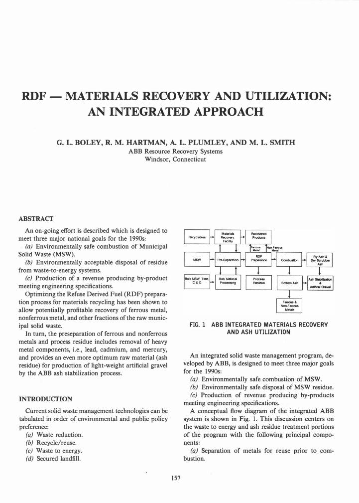
FIG. 1 ABB INTEGRATED MATERIALS RECOVERY
AND ASH UTILIZATION
An integrated solid waste management program, developed by ABB, is designed to meet three major goals for the 1990s:
(a) Environmentally safe combustion of MSW. (b) Environmentally safe disposal of MSW residue. (c) Production of revenue producing by-products
meeting engineering specifications. A conceptual flow diagram of the integrated ABB
system is shown in Fig. 1. This discussion centers on the waste to energy and ash residue treatment portions of the program with the following principal components:
(a) Separation of metals for reuse prior to combustion.

INSPECTIONI FERROUS
SEPARATION PRIMARY
MSW
RE�'1VA� ME[TAl
SECONDARY
RECEIVING MAGNETIC SHREDDFOER
� .A _
._ TROMMEl
�- � �L···�A1 PRIMARY � _ ..... ;p� SHREDDER �--.../ � RDF
RESIDUE SECONDARY STORAGE TROMMEl
FIG.2 MUNICIPAL SOLID WASTE PROCESSING
SYSTEM - SINGLE LINE
(b) Combustion of organic material with high combustion efficiency followed by flue gas clean up with a state-of-the-art emission control system.
(c) Removal of metals from the bottom ash for reuse and processing/stabilization of the remaining combustion residue (bottom ash plus fly ash).
The ABB integrated solid waste management system uses proven technology.
Currently, ABB has three operating RDF facilities employing essentially identical front-end processing technology and boiler design features. These facilities are: the Mid-Connecticut facility (Mid-CT) in Hartford, Connecticut, with dry scrubber/fabric filter (DS/ FF) technology; the Greater Detroit Resource Recovery Facility (GDRRF) facility in Detroit, Michigan, currently with lime addition and electrostatic precipitator (ESP) technology, but in the process of converting to DS/FF; and the Honolulu Resource Recovery Venture facility (H-Power) in Honolulu, Hawaii with dry scrubber/electrostatic precipitator (DS/ESP) technology.
SYSTEM DESCRIPTION
The flow of waste through the waste processing system at an ABB process facility is shown in Fig. 2. The process equipment is arranged to minimize changes in flow direction and material transfer points.
Incoming trucks are weighed and then directed to the MSW receiving area, where the waste is discharged on the receiving building floor. Front-end loaders are used to stockpile and feed process lines and inspect for the presence of nonprocessible items, which are separated for removal.
Studies by Franklin Associates [1] indicate that most of the lead in MSW enters the waste stream from household and lead-acid batteries, or consumer electronics (lead in paints and steel cans has decreased by 9�95% since 1970). Cadmium enters primarily in household batteries, plastics, and consumer electronics, while mercury enters in household batteries, electric lighting fixtures, thermometers, and thermostats.
158
On the basis of preliminary testing at the MidConnecticut facility in 1988-1989, [2] for every 1000 tons of MSW, there is approximately 40 tons of ferrous metal (iron), 780 lb of lead, 5 lb of cadmium, and 2.4 lb of mercury and about 130 tons of noncombustible materials such as glass, ceramics, aluminum, copper, or brass.
Preparation of Nonprocessible Items
MSW is loaded into a feed conveyor by front-end loaders and metered by the feed conveyor onto an inclined steel pan conveyor for leveling. The inclined conveyor carries the waste onto a horizontal, steel conveyor which feeds the primary shredder. Prior to the shredder, a picking station is located along side each horizontal feed conveyor to allow the operator to inspect the waste being transported to the primary shredder and to stop the conveyor and remove non processible items. Nonprocessible items are removed using a hydraulic grapple controlled from a picking station control booth.
Processing of the Waste Stream into RDF
The primary shredder is a flail mill which performs coarse shredding of the waste stream. Closed bags are opened, ferrous metal is exposed, and glass containers are broken. Each primary shredder is enclosed in a reinforced concrete room equipped with a dedicated dust control system consisting of an exhaust fan and fabric filter.
After primary shredding, the waste is conveyed to the ferrous metal separation system consisting of a primary electromagnetic drum and a secondary drum type transfer magnet. The waste is then conveyed to the primary separation unit which is a totally enclosed trommel. Three discharge streams are conveyed from the trommel. One is a process residue stream which consists of small rocks, broken pieces of glass and other items which fall through small holes in the front section of the trommel. The second stream is a sized fraction consisting of small combustible products, aluminum cans, and medium sized noncombustibles. This stream is transported to the secondary trommel. The third stream is an oversized fraction consisting primarily of paper and plastic which is conveyed to the secondary shredder for size reduction.
The secondary trommel further separates the sized fraction received from the primary separation units. The discharge streams consist of:
(a) Process residue consisting of fine sand, glass, dirt, etc., which is conveyed directly to the residue
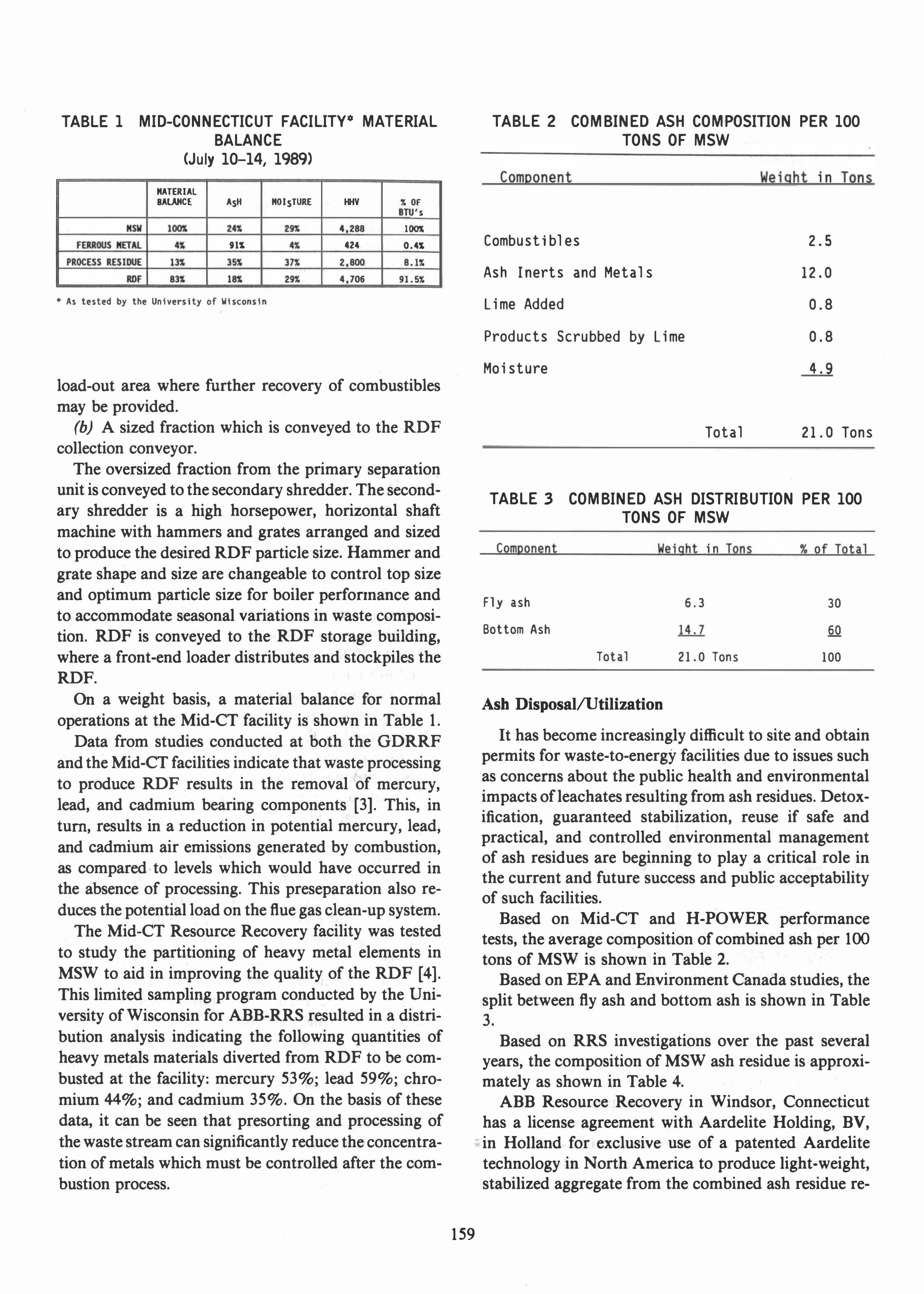
TABLE 1 MID-CONNECTICUT FACILITYo MATERIAL
BALANCE
(July 10-14, 1989)
MATERIAL BAlAHCE ASH
91S
• As tested by the University of Wisconsin
MOISTURE HHV � OF s
1001
424 0.4S
5l1\
load-out area where further recovery of combustibles
may be provided.
(b) A sized fraction which is conveyed to the RDF
collection conveyor.
The oversized fraction from the primary separation unit is conveyed to the secondary shredder. The secondary shredder is a high horsepower, horizontal shaft
machine with hammers and grates arranged and sized
to produce the desired RDF particle size. Hammer and
grate shape and size are changeable to control top size
and optimum particle size for boiler perfollnance and
to accommodate seasonal variations in waste composi
tion. RDF is conveyed to the RDF storage building,
where a front-end loader distributes and stockpiles the
RDF.
On a weight basis, a material balance for normal
operations at the Mid-CT facility is shown in Table 1.
Data from studies conducted at both the GDRRF
and the Mid-CT facilities indicate that waste processing
to produce RDF results in the removal of mercury,
lead, and cadmium bearing components [3]. This, in
tum, results in a reduction in potential mercury, lead,
and cadmium air emissions generated by combustion,
as compared· to levels which would have occurred in
the absence of processing. This preseparation also re
duces the potential load on the flue gas clean-up system.
The Mid-CT Resource Recovery facility was tested
to study the partitioning of heavy metal elements in
MSW to aid in improving the quality of the RDF [4].
This limited sampling program conducted by the Uni
versity of Wisconsin for ABB-RRS resulted in a distri
bution analysis indicating the following quantities of
heavy metals materials diverted from RDF to be com
busted at the facility: mercury 53%; lead 59%; chro
mium 44%; and cadmium 35%. On the basis of these
data, it can be seen that presorting and processing of
the waste stream can significantly reduce the concentra
tion of metals which must be controlled after the com
bustion process.
159
TABLE 2 COMBINED ASH COMPOSITION PER 100
TONS OF MSW
Component
Combustibles
Ash Inerts and Metals
Lime Added
Products Scrubbed by Lime
Moisture
Total
Weight in Tons
2.5
12.0
0.8
0.8
4.9
21.0 Tons
TABLE 3 COMBINED ASH DISTRIBUTION PER 100
TONS OF MSW
Component
Fly ash
Bottom Ash
Total
Weight in Tons
6.3
14.7
21.0 Tons
Ash Disposal/utilization
% of Total
30
§Q
100
It has become increasingly difficult to site and obtain permits for waste-to-energy facilities due to issues such as concerns about the public health and environmental impacts of leachates resulting from ash residues. Detoxification, guaranteed stabilization, reuse if safe and practical, and controlled environmental management of ash residues are beginning to play a critical role in the current and future success and public acceptability of such facilities.
Based on Mid-CT and H-POWER performance tests, the average composition of combined ash per 100 tons of MSW is shown in Table 2.
Based on EPA and Environment Canada studies, the split between fly ash and bottom ash is shown in Table 3.
Based on RRS investigations over the past several years, the composition of MSW ash residue is approximately as shown in Table 4.
ABB Resource Recovery in Windsor, Connecticut
has a license agreement with Aardelite Holding, BV, in Holland for exclusive use of a patented Aardelite
technology in North America to produce light-weight, stabilized aggregate from the combined ash residue re-

TABLE 4 ASH COMPOSITION
65% Minus 3/4" mostly composed of ash fines -3/S- and glass
SiD, Sil iea Oxide (glass) 57. g
Al,O, Aluminum Oxide 9.7
Fe,O, Iron Oxide 7.1
C.O Calcium Oxide 9.3
MgO Magnesium Oxide 2.2
Na,O Sodium Oxide 6.1
Ignition Loss 2.7
Carbon 1. 6
Other 3.4
35% Plus 3/4" mostly composed of friable ash with lessor quantities of
metals, glass, and ceramics and unburned pieces of wood, rubber, textile,
and paper in the approximate fo11owing percentages:
Friable ash, glass. and ceramics 77
Ferrous metal
Non-ferrous metal
Combustibles
FIVllh, Bottom Ash or Combined Ash
15
Embeddln
Mlt.rI,1
Sleam
CurIng
Screening
Finished Product
FIG.3 DIAGRAM OF THE ABB ARTIFICIAL GRAVEL
PROCESS FOR CONVERSION OF INCINERATOR
RESIDUE TO LIGHTWEIGHT AGGREGATE
suIting from the combustion of municipal solid waste (MSW). The process (Fig. 3) blends the incinerator residue with binder and water (and possibly other constituents) in a mixer. The "green" mixture is then pelletized on a spinning disk pelletizer and dusted with an embedding material to prevent caking. The resulting product is cured in a steam-filled silo.
160
ABB recently completed a test program, [5] comprised of three phases, in which bottom ash (BA) and baghouse ash (BHA) were collected separately at an RDF fired resource recovery facility. These residues were blended and processed in Holland to make lightweight aggregate pellets and subjected to testing to confirm both their environmental and structural integrity. Specific program objectives were:
(a) Determine the viability of the process for producing pellets from MSW residue.
(b) Determine structural and leaching potential of a range of residue mixtures.
(c) Evaluate the effects of various admixtures.
In addition to bench-scale testing, the test program included a series of four demonstration runs using Aardelite's 3 tonslhr pilot facility.
Results of Bench and Pilot Test Runs
The following discussion compares leaching test results from bench-scale treated artificial gravel production in Holland during November 1988 (Series I), February 1990 (Series II), and April/May 1990 (Series III) and untreated ash samples. More comprehensive leaching test results are also available from four largescale pilot production runs in April/May 1990 when 3-9 tons of light-weight aggregate pellets were produced in each run.
(a) Leaching studies show that samples of untreated RDF incinerator bottom ash tend to produce leachate which exceeds EPA limits for lead and occasionally may exceed those limits for cadmium. Baghouse ash tends to produce leachate which is above EPA limits from cadmium and may occasionally be above those limits for lead, arsenic, selenium, and mercury (see Table 5).
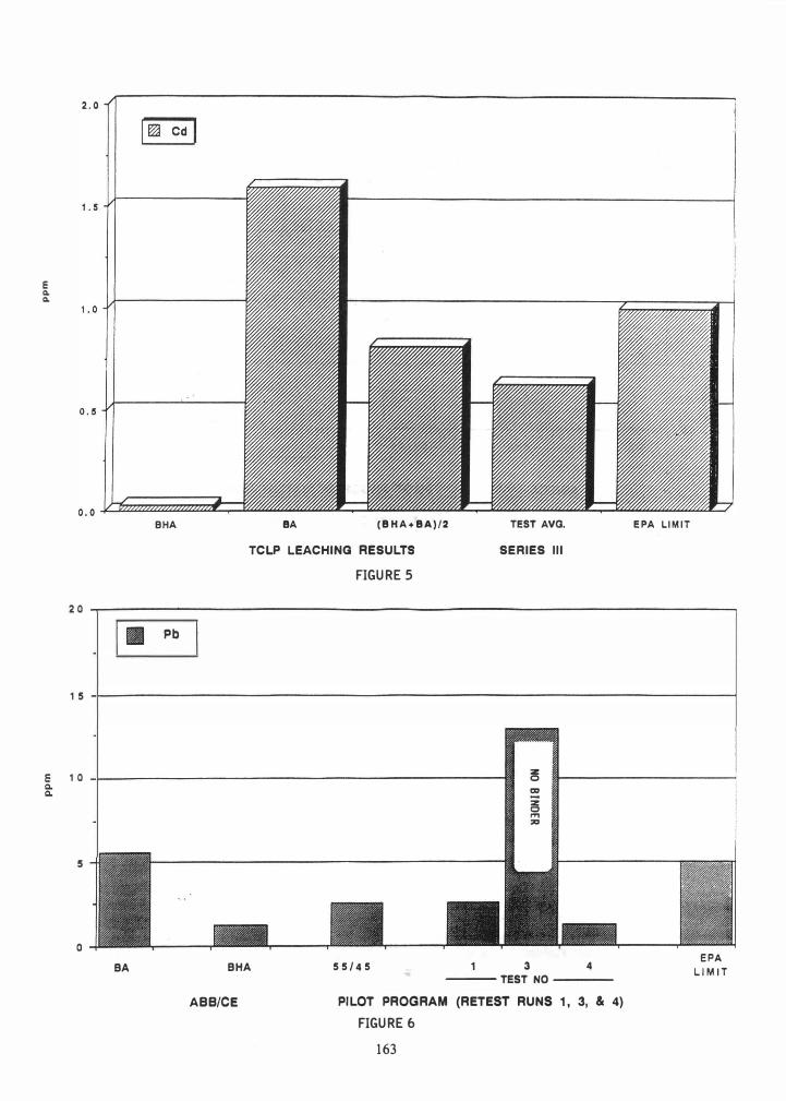
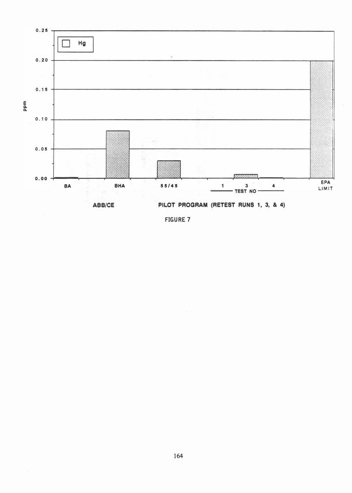
(b) ABB light-weight aggregate (artificial gravel) prepared from combined ash resulted in reduction of the leachability of heavy metals on the basis of analysis of some 216 test mixtures from three different composite Mid-Com�ecticut ash collections. Although even lower leachate levels would be desirable, EPA limits were exceeded in only one case when tested by the TCLP procedure. Figures 4--7 show typical fixation of lead, cadmium, and mercury.
(c) Completion of four extended pilot test runs utilizing RDF ash provided sufficient operating data that a viable commercial plant can be designed.
The resulting pellets are suitable for utilization in various products or processes which incorporate gravel. These products weigh only about 60% of their natural gravel counterparts. A second phase of field utilization studies is planned.
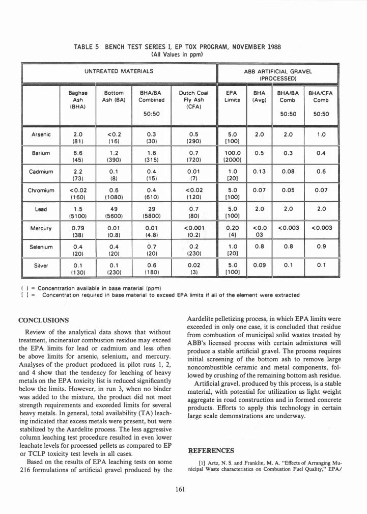
TABLE 5 BENCH TEST SERIES I, EP TOX PROGRAM, NOVEMBER 1988 (All Values in ppm)
UNTREATED MATERIALS ABB ARTIFICIAL GRAVEL
(PROCESSED)
Baghse Bottom BHA/BA Dutch Coal EPA BHA BHA/BA BHA/CFA Ash Ash (BA) Combined Fly Ash Limits (Avg) Comb Comb
(BHA) (CFA)
50:50 50:50 50:50
Arsenic 2.0 <0.2 0.3 0.5 5.0 2.0 2.0 1.0
(81 ) (16) (30) (290) (100)
Barium 6.6 1.2 1.6 0.7 100.0 0.5 0.3 0.4
(45) (390) (315) (720) [2000)
Cadmium 2.2 0.1 0.4 0.01 1.0 0.13 0.08 0.6
(73) (8) (15) (7) [20)
Chromium <0.02 0.6 0.4 <0.02 5.0 0.07 0.05 0.07
(160) (1080) (610) (120) (100)
Lead 1.5 49 29 0.7 5.0 2.0 2.0 2.0
(5100) (5600) (5800) (80) (100)
Mercury 0.79 0.01 0.01 <0.001 0.20 <0.0 <0.003 <0.003
(38) (0.8) (4.8) (0.2) (4) 03
Selenium 0.4 0.4 0.7 0.2 1.0 0.8 0.8 0.9
(20) (20) (20) (230) (20)
Silver 0.1 0.1 0.6 0.02 5.0 0.09 0.1 0.1
(130) (230) (180) (3) [100)
( ) = Concentration available in base material (ppm)
[ 1 = Concentration required in base material to exceed EPA limits if all of the element were extracted
CONCLUSIONS
Review of the analytical data shows that without treatment, incinerator combustion residue may exceed the EPA limits for lead or cadmium and less often be above limits for arsenic, selenium, and mercury. Analyses of the product produced in pilot runs 1, 2, and 4 show that the tendency for leaching of heavy metals on the EPA toxicity list is reduced significantly below the limits. However, in run 3, when no binder was added to the mixture, the product did not meet strength requirements and exceeded limits for several heavy metals. In general, total availability (TA) leaching indicated that excess metals were present, but w�re stabilized by the Aardelite process. The less aggressIve column leaching test procedure resulted in even lower leachate levels for processed pellets as compared to EP or TCLP toxicity test levels in all cases.
Based on the results of EPA leaching tests on some 216 formulations of artificial gravel produced by the
161
Aardelite pelletizing process, in which EPA limits were exceeded in only one case, it is concluded that residue from combustion of municipal solid wastes treated by ABB's licensed process with certain admixtures will produce a stable artificial gravel. The process requires initial screening of the bottom ash to remove large noncombustible ceramic and metal components, followed by crushing of the remaining bottom ash residue.
Artificial gravel, produced by this process, is a stable material, with potential for utilization as light weight aggregate in road construction and in formed concrete products. Efforts to apply this technology in certain large scale demonstrations are underway.
REFERENCES
[I] Artz, N. S. and Franklin, M. A. "Effects of Arranging Municipal Waste characteristics on Combustion Fuel Quality," EPA!

e Q. Q.
20
15
10
5
o
10 Pb I
BHA BA (BHA+BA)/2 TEST AVO. EPA LIMIT
TCLP LEACHING RESULTS SERIES III
The five columns of data in figures 4 and 5 are identified as:
1. SHA· Raw/Untreated baghouse ash
2. SA • Raw/Untreated bottom ash
3. (SHA + SA) • Mathematical averages of 1 and Z --2-
4. Average Test Series III Results
5. EPA Limits
FIGURE 4
AWMA Conference on Municipal Waste Combustion, Tampa, Florida, April 1991.
[2] Boley, G. L. "Partioning of Elements by Refuse Processing," EPA/AWMA Conference Municipal Waste Combustion, Tampa, Florida, April 1991.
[3] Pierce, G. G. "Controlling Mercury Emissions from RDF Facilities," EP AI A WMA Conference on Municipal Waste Combustion, Tampa, Florida, April 1991.
162
[4] Ham, R. K. and Hammer, V. A. "Elemental Composition and Partitioning of Metals at Madison and Mid-Connecticut Resource Recovery Plants," University of Wisconsin-Madison, July 1991.
[5] Plumley, A. L. and Boley, G. L. "ABB Ash Treatment Technologies," In Proceedings of the Third International Conference on Ash Utilization and Solidization. Arlington, Virginia, November 1990.
E Q. Q.
E Q. Q.
2.0
BHA BA (BHA+BA)/2 TEST AVO. EPA LIMIT
TCLP LEACHING RESULTS SERIES III
FIGURE 5
20 �--------------------------------------------------------------------------�
Pb
15 4--------------------------------------------�
1 0
5
o SA SHA
ABB/CE
:z 0 a:I -:z c ,.., :;a
55/45 3 4 ---- TEST NO ----
PILOT PROGRAM (RETEST RUNS 1, 3, & 4)
FIGURE 6
163
EPA LIMIT
0.25 ,---------------------------------------------------------------------�
I D Hg
0.20 ;-----------------------------------------------------------------���
0.15 �----------------------------------------------------------------�::::::::
0.10 �----------------------------------------------------------------� ::::::::::::
0.05 1-------------t:1:1��1��:���m:r_-
-------------------------------------------l
BA BHA 55/45 3 4 --- TEST NO ---
ABB/CE PILOT PROGRAM (RETEST RUNS 1, 3, & 4)
FIGURE 7
164
EPA LIMIT