Embed Size (px)
Citation preview

33RD INTERNATIONAL COSMIC RAY CONFERENCE, RIO DE JANEIRO 2013THE ASTROPARTICLE PHYSICS CONFERENCE
4m Davies-Cotton telescope for the Cherenkov Telescope ArrayR. MODERSKI4 , J.A. AGUILAR6, A. BARNACKA4, A. BASILI6,9 , V. BOCCONE6 , L. BOGACZ3, F. CADOUX6,A. CHRISTOV6 , M. DELLA VOLPE6, M. DYRDA2, A. FRANKOWSKI4 , M. GRUDZINSKA10 , M. JANIAK4 ,M. KARCZEWSKI5, J. KASPEREK1, W. KOCHANSKI2, P. KOROHODA1 , J. KOZIOŁ3, P. LUBINSKI4, J. LUDWIN2 ,E. LYARD8, A. MARSZAŁEK3 , J. MICHAŁOWSKI2 , T. MONTARULI6, J. NICOLAU-KUKLINSKI5, J. NIEMIEC2 ,M. OSTROWSKI3 , Ł. PŁATOS5 , P.J. RAJDA1 , M. RAMEEZ6, W. ROMASZKAN1, M. RUPINSKI1 , K. SEWERYN5 ,M. STODULSKA3 , M. STODULSKI2 , R. WALTER8 , K. WINIARSKI1 , Ł. WISNIEWSKI5 , A. ZAGDANSKI3 , K. ZIETARA3 ,P. ZIOŁKOWSKI2 , P. ZYCHOWSKI2 FOR THE THE CTA CONSORTIUM
1 Faculty of Computer Science, Electronics, and Telecommunications, AGH University of Science and Technology, Al. Mickiewicza 30,30-059 Cracow, Poland2 Institute of Nuclear Physics, Polish Academy of Sciences, ul. Radzikowskiego 152, 31-342 Cracow, Poland3 Jagiellonian University, ul. Orla 171, 30-244 Cracow, Poland4 Nicolaus Copernicus Astronomical Center, Polish Academy of Sciences, ul. Bartycka 18, 00-716 Warsaw, Poland5 Space Research Centre, Polish Academy of Sciences, ul. Bartycka 18A, 00-716 Warsaw, Poland6 Departement de physique nucleaire et corpusculaire, Universite de Geneve, CH-1211, Switzerland7 ETH Zurich, Inst. for Particle Physics, Schafmattstr. 20, CH-8093 Zurich, Switzerland8 ISDC Data Centre for Astrophysics, Observatory of Geneva, Universite de Geneve, Chemin dEcogia 19, CH-1290 Versoix, Switzerland9 Physik Institut, Universitat Zurich, Winterthurerstr. 190, CH-8057, Switzerland10 Astronomical Observatory, Warsaw University, Al. Ujazdowskie 4, 00-478 Warsaw, Poland
Abstract: The Cherenkov Telescope Array (CTA) is the next generation very high energy gamma-ray observatory.It will consist of three classes of telescopes, of large, medium and small sizes. The small telescopes, of 4mdiameter, will be dedicated to the observations of the highest energy gamma-rays, above several TeV. We presentthe technical characteristics of a single mirror, 4m diameter, Davies-Cotton telescope for the CTA and theperformance of the sub-array consisting of the telescopes of this type. The telescope will be equipped with afully digital camera based on custom made, hexagonal Geiger-mode avalanche photodiodes. The developmentof cameras based on such devices is an RnD since traditionally photomultipliers are used. The photodiodes arenow being characterized at various institutions of the CTA Consortium. Glass mirrors will be used, although analternative is being considered: composite mirrors that could be adopted if they meet the project requirements.We present a design of the telescope structure, its components and results of the numerical simulations of thetelescope performance.
Keywords: imaging atmospheric Cherenkov telescope, CTA
1 IntroductionThe Cherenkov Telescope Array (CTA) will be the nextgeneration observatory of the very high energy (VHE;> 10GeV) gamma rays [1]. It will provide unprecedentedsensitivity in the energy range 10GeV-300TeV. To achieveits goals the array will consists of at least tree types oftelescopes. The sensitivity in the highest energy range,above several TeV, will be provided by the sub-array ofthe, so called, “small size telescopes” (SSTs). The SST sub-array is expected to include around 70 telescopes.
A prototype of an SST is currently being developedby a consortium of Polish and Swiss institutions. Theprototype will be based on the proven Davies-Cotton (DC)design, used in the currently operated VHE gamma-rayobservatories like H.E.S.S. or VERITAS. A new idea is toequip the telescope with a fully digital camera based onsilicon photodetectors. The overall view of the telescope ispresented in Fig. 1.
2 4m Davies-Cotton Small Size Telescope2.1 StructureThe telescope frame and the drive system has been designedat the Institute of Nuclear Physics, Polish Academy ofSciences (INP) in Krakow, Poland. The frame is made ofsteel. A camera is placed in front of the mirror dish on aquadrupod. The dish is fixed to the dish support structure,that contains the counterweights, and is mounted on thetelescope support. The quadrupod is connected to the dishsupport in order not to deliver any direct stress on the mirror.
The telescope support consists of a tower fitted with anazimuth drive system, and a special head with an elevationdrive. Both the azimuth and the elevation drive systemsare based on a set of a roller-bearing and an IMO slewtransmission equipped with two servo-motors. When inhorizontal position the overall dimensions of the telescopeare roughly 5m height × 9m long × 3.5m wide. Theweight of the telescope is around 9t. For a transportationfrom a production site to the assembly point three telescopestructures can be packed in a standard, open-top 12mcontainer.
The telescope structure design has been optimized and
arX
iv:1
307.
3137
v1 [
astr
o-ph
.IM
] 1
1 Ju
l 201
3

4m telescope for the CTA33RD INTERNATIONAL COSMIC RAY CONFERENCE, RIO DE JANEIRO 2013
Figure 1: The general view of the 4m Davies-Cotton smallsize telescope based on the technical documentation.
checked for conformance with the CTA specificationsthrough the Finite Element Method (FEM) analysis. Suchanalysis delivers information on the telescope deformationand mechanical stresses, camera displacement, and struc-ture eigenfrequencies for various loads, including the grav-ity, earthquake, snow and ice, and the wind conditions ex-pected at a future CTA site. For the regular observing con-ditions the maximum camera displacement with respect tothe mirror dish is about 8mm, which is 1/3 of the physi-cal pixel size. The structure is also strong enough to sus-tain all extreme load cases – the mechanical stresses in thestructure are well below the plasticity of the materials used.Finally, the lowest eigenfrequencies of the structure are3.8Hz, 4.5Hz, and 11.4Hz. For more details on the tele-scope structure see [2].
2.2 MirrorThe main telescope mirror has a spherical shape and thefocal length of f = 5.6m. It consists of 18 hexagonalfacets of 78cm dimension (flat-to-flat). The facets are alsospherical with a radius of curvature R = 2 f = 11.2m. Sucha number of facets and the facet size has been chosen tomaximize the mirror area, while keeping the point spreadfunction (PSF) of the mirror within the required 0.25◦. Thetotal mirror area corrected for facets inclination is 9.42m2,while the PSF, determined through ray-tracing, is 0.21◦for the rays at an off-axis angle of 4◦. A camera housingtogether with a quadrupod causes a shadowing of 20% ofthe light, thus the final collecting area of the mirror is 7.6m2.The mirror is not isochronous, but the optical time spread isless than 0.84ns (rms).
Glass mirror facets are foreseen for the telescope. Glasswill be coated with Al+SiO2+HfO2 coating to maximizethe reflectance and provide weatherability. The expectedaverage reflectance is of the order of 94% in the wavelengthrange 300− 550nm. Alternative coatings may be consid-ered for the mirror, which include simple Al+SiO2, or mul-tilayer dielectric coating.
2.2.1 Alternatives to glass mirrorsTwo alternatives for the glass mirrors are currently be-ing developed at the Space Research Centre of the PolishAcademy of Sciences, Warsaw (SRC) and INP. Both tech-nologies use composite materials instead of glass to speed
up the production process and reduce the mirror mass. SRCtechnology is based on sheet moulding compound (SMC)– a fiber reinforced thermoset material, formed in a hightemperature, high pressure steel mold. The coating is ap-plied directly on the composite surface (see Fig. 2). In thetechnology developed by INP an aluminum V-shaped hon-eycomb structure is used to support two glass panels andadditional 1mm thick glass sheet is cold slumped on thespherical layer of epoxy resin. Deposition of resin layer andcold slumping is performed on the mould. Both technolo-gies are now intensively tested to prove the fulfillment ofthe requirements.
Figure 2: 7 composite mirror prototypes (2 coated) devel-oped at the Space Research Centre.
2.2.2 Mirror adjustment systemEach mirror facet is going to be equipped with the justifi-cation system to allow focusing of the whole mirror. Foreach facet the system consists of tree actuators: one fixed,one movable with one degree of freedom, and one movablewith two degrees of freedom. Control electronics completesthe system. To reduce the number of cables the movable ac-tuators are going to be controlled wirelessly. The focusingis performed by observing the image of stars on the lid ofthe main telescope camera with a dedicated CCD camera.Three versions of the system are currently being developedby Universitat Zurich, SRC (see Fig. 3), and UniversitatTubingen. The system will be able to position the mirrorfacets with 2 µm accuracy.
2.3 CameraThe main telescope camera is based on the FlashCamconcept [3] and bears the working name DigiCam. Thedesign separates the photon detection plane (PDP) fromthe camera electronics thus allowing these two parts to bephysically placed in different locations, e.g. PDP in thefocal plane of the telescope and camera electronics in abox outside of the telescope structure. In the camera thesignal coming from the photodetectors, after amplificationand possibly shaping, is digitized and both trigger decisionsand readout is done on digital signal. Such a scheme allowsfor a great flexibility in trigger algorithms and readoutorganization.
Contrary to the original FlashCam design DigiCam willuse the Geiger avalanche photodiodes (G-APD) instead ofthe vacuum tube photomultipliers (PMT) [6]. These are new

4m telescope for the CTA33RD INTERNATIONAL COSMIC RAY CONFERENCE, RIO DE JANEIRO 2013
Figure 3: Two prototype actuators build at the Space Re-search Centre.
semiconductor photodetectors used with a great success inthe FACT camera [4]. They allow for a smaller size of thePDP, do not require a high voltage, and offer very goodphoton resolution. G-APDs, contrary to PMT, do not sufferfrom aging, thus allowing for observations being performedduring moonlight.
The DigiCam camera will consist of 1296 pixels orga-nized in 108 modules of 12 pixels. With an angular pixelsize of 0.25◦ the whole camera will offer 9◦ field of view.The total camera weight is expected to be about 300kg andshould fit into a cylinder of dimensions 1.2m diameter ×1m length.
The DigiCam focal plane is developed by Universite deGeneve and Universitat Zurich. For the readout electronics,the FlashCam readout system (see [3]) will be adopted.
2.3.1 Photon detection planeThe heart of the PDP is the Hamamtsu S12516 detector(see Fig. 4). It is a four-channel, hexagonal shape G-APDwith 50 µm or 100 µm cell size, 94mm2 total area offering35% − 40% photon detection efficiency at the suppliedvoltage of 70V. Few prototypes of this new G-APD areunder study (see [5]) and the first measurement seems toconfirm the performance to be what was expected. Thedevices also show a reasonable dark current rate and cross-talk despite their large area. 12 detectors will be mounted onsingle module board, which will also host the preamplifier,slow control system and power supply. 108 of such boardswill constitute the whole PDP.
A mosaic of light concentrators will be placed in frontof the photodetectors to reduce the dead space and cut offbackground light not coming from the mirror. After analysisan empty, hexagonal cone has been chosen with the entrancesize of 23.2mm and compression factor of 6. The shapeof the cone has been optimized using Bezier curves andthe cut-off angle has been determined to be 24◦. Prototypelight concentrators have been fabricated at the companyINITIAL and an optimal coating is under development incollaboration with Thin Film in Zurich.
Light concentrators will be covered with an entrancewindow to provide protection against water and dust. The
Figure 4: Hamamatsu S12516 Geiger-mode avalanche pho-todiode.
window will be made of BOROFLOAT R© 33 borosilicateglass from SCHOTT. The window can be coated with adichroic filter to reduce the amount of nigh sky backgroundlight entering the PDP. The optimal wavelengths of the filterare under investigation. It is under consideration also theapplication of an anti-reflective coating.
2.3.2 Camera electronicsDigiCam plans to adopt the readout system of the FlashCam.Analog signals from the PDP will be transferred via CATxcable to camera electronic box, where they are digitizedusing 12 bit, 250MS/s TI ADS41B29 FADCs. 12 of suchconverters are placed on a single “FADC board”, and two ofsuch boards can be mounted on a single motherboard (seeFig. 5). Each motherboard will host a FPGA chip whichwill be responsible for signal processing. 54 motherboardswill be required to handle signals from all 1296 pixels.They will be located in 9 crates and connected through aspecial backplanes. A separate set of “trigger boards” willbe necessary to collect trigger data from FADC cards anddistribute clock and trigger signals back to FADC cards.Following the central trigger signal the data will be sent tothe central data acquisition system.
Figure 5: Single motherboard with two FADC cards undertests at the Max-Planck Institut fur Kernphysik, Heidelberg.
The concept of digitization and data transmission hasbeen extensively tested with demonstrator setups. It wasshown that 2150MB/s sustained data transfer is possiblewithout packet loss using raw Ethernet protocol for up to 84simulated FADC boards resulting in the estimated maximalevent rate after central trigger of 22kHz. The performance
4m telescope for the CTA33RD INTERNATIONAL COSMIC RAY CONFERENCE, RIO DE JANEIRO 2013
of standard CAT5/6 cables to transfer analog signals hasbeen verified.
3 Telescope performanceThe expected telescope performance has been estimatedthrough a number of numerical simulations of signal pro-cessing, of a single telescope and of an array of the tele-scopes. All simulations have been performed for a Hama-matsu S10985 chip as at the time of the data generation nomeasurements for the newest S12516 photodetector wereavailable. The present measurements (see [5]), however,show that the real performance of the device are compati-ble with the assumed PDE spectrum used in the simulation.Light concentrators transmission curve was calculated us-ing ZEMAX ray-tracing software (see [5]). The altitude of2000m is assumed for the simulations.
Signal reconstruction procedure has been investigatedto verify the accuracy of the estimation of the intensity ofthe Cherenkov light. The simulation procedure involvesgeneration of signal in photodetector, change of the signalshape by preamplifiers and filters, signal digitization, andsignal reconstruction using convolution of smoothed signalwith its derivative. It was shown that for sampling rateof 250MS/s, electronic noise rms corresponding to 15%of single photoelectron (PE) signal, and thermal noise of0.6MHz the systematic error on the absolute intensity of theCherenkov light is less than 8.5% for a signal amplitudesabove 20PE. This is less than required value of 10% forSST. For amplitudes larger than 50PE the error is less than5%. The estimated error of the photon arrival time is lessthan 0.6ns.
For a single telescope one of the important parameteris the level of the night sky background (NSB). It is thedetection rate of background photons in a single pixel ofthe camera. The NSB level strongly depends on the opticalproperties of the mirror and the quantum efficiency of thephoton detector. For our telescope the nominal (dark sky)NSB level has been estimated to be 85MHz, and 32MHzfor Al+SiO2+HfO2 and dielectric coating, respectively. Thelow NSB level for dielectric coating is caused by negligablereflectance of this coating beyond 550nm, where the NSBintensity increases significantly. The same effect can beachieved for Al+SiO2+HfO2 coating by introduction of afilter in the optical path of the telescope. The expected NSBlevel for partial moonlight conditions is five times higherthan the nominal level.
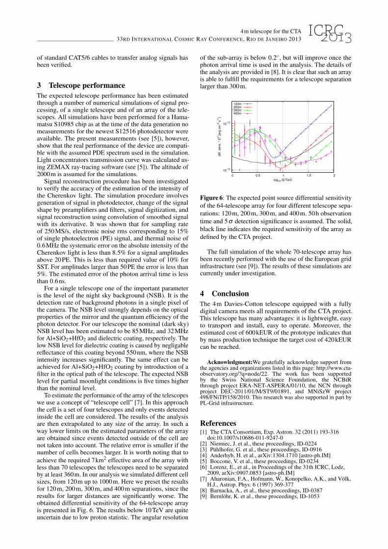
To estimate the performance of the array of the telescopeswe use a concept of “telescope cell” [7]. In this approachthe cell is a set of four telescopes and only events detectedinside the cell are considered. The results of the analysisare then extrapolated to any size of the array. In such away lower limits on the estimated parameters of the arrayare obtained since events detected outside of the cell arenot taken into account. The relative error is smaller if thenumber of cells becomes larger. It is worth noting that toachieve the required 7km2 effective area of the array withless than 70 telescopes the telescopes need to be separatedby at least 360m. In our analysis we simulated different cellsizes, from 120m up to 1000m. Here we preset the resultsfor 120m, 200m, 300m, and 400m separations, since theresults for larger distances are significantly worse. Theobtained differential sensitivity of the 64-telescope arrayis presented in Fig. 6. The results below 10TeV are quiteuncertain due to low proton statistic. The angular resolution
of the sub-array is below 0.2◦, but will improve once thephoton arrival time is used in the analysis. The details ofthe analysis are provided in [8]. It is clear that such an arrayis able to fulfill the requirements for a telescope separationlarger than 300m.
10-13
10-12
0 0.5 1 1.5 2
diff.
se
ns.
* E
2 [
erg
cm
-2 s
-1]
log10 (E/TeV)
120m200m300m400m
Figure 6: The expected point source differential sensitivityof the 64-telescope array for four different telescope sepa-rations: 120m, 200m, 300m, and 400m. 50h observationtime and 5σ detection significance is assumed. The solid,black line indicates the required sensitivity of the array asdefined by the CTA project.
The full simulation of the whole 70-telescope array hasbeen recently performed with the use of the European gridinfrastructure (see [9]). The results of these simulations arecurrently under investigation.
4 ConclusionThe 4m Davies-Cotton telescope equipped with a fullydigital camera meets all requirements of the CTA project.This telescope has many advantages: it is lightweight, easyto transport and install, easy to operate. Moreover, theestimated cost of 600kEUR of the prototype indicates thatby mass production technique the target cost of 420kEURcan be reached.
Acknowledgment:We gratefully acknowledge support fromthe agencies and organizations listed in this page: http://www.cta-observatory.org/?q=node/22. The work has been supportedby the Swiss National Science Foundation, the NCBiRthrough project ERA-NET-ASPERA/01/10, the NCN throughproject DEC-2011/01/M/ST9/01891, and MNiSzW project498/FNiTP/158/2010. This research was also supported in part byPL-Grid infrastructure.
References[1] The CTA Consortium, Exp. Astron. 32 (2011) 193-316
doi:10.1007/s10686-011-9247-0[2] Niemiec, J. et al., these proceedings, ID-0224[3] Puhlhofer, G. et al., these proceedings, ID-0916[4] Anderhyb, H. et al., arXiv:1304.1710 [astro-ph.IM][5] Boccone, V. et al., these proceedings, ID-0234[6] Lorenz, E., et al., in Proceedings of the 31th ICRC, Lodz,
2009, arXiv:0907.0853 [astro-ph.IM][7] Aharonian, F.A., Hofmann, W., Konopelko, A.K., and Volk,
H.J., Astrop. Phys. 6 (1997) 369-377[8] Barnacka, A., et al., these proceedings, ID-0387[9] Bernlohr, K. et al., these proceedings, ID-1053