Embed Size (px)
Citation preview

RCI-1550 HRT Lattice Boom SystemInstruction Manual
MAN-1075 Rev D
LSI-Robway Pty Limited, 32 West Thebarton Road, Thebarton, South Australia, 5031Phone: +61 (0) 8 8238 3500 Fax: +61 (0) 8 8352 1684 www.lsirobway.com.au


CONTENTS
1. IMPORTANT SAFETY NOTICE ...................................................................................................................... 5
2. SPECIAL NOTES ................................................................................................................................................ 5
2.1. BRANDNAMES, TRADENAMES AND TRADE MARKS. ............................................................................................ 5 2.2. IMPORTANT SAFETY NOTICE ............................................................................................................................... 5 2.3. LIMITED PRODUCT WARRANTY........................................................................................................................... 6 2.4. GLOSSARY OF SOME USED TERMS........................................................................................................................ 6
3. INTRODUCTION ................................................................................................................................................ 6
3.1. MANUAL CONTENTS............................................................................................................................................ 6 3.2. SCOPE OF MANUAL.............................................................................................................................................. 6 3.3. INTENDED AUDIENCE .......................................................................................................................................... 6 3.4. PERSONNEL QUALIFICATIONS.............................................................................................................................. 6
4. SYSTEM DESCRIPTION ................................................................................................................................... 7
4.1. APPLICATION....................................................................................................................................................... 7 4.2. PURPOSE.............................................................................................................................................................. 7 4.3. CAPABILITIES ...................................................................................................................................................... 7 4.4. AVAILABLE OPTIONS........................................................................................................................................... 8
5. INSTALLATION - GENERAL........................................................................................................................... 9
5.1. SETTING UP THE CRANE ...................................................................................................................................... 9 5.2. ANGLE SENSORS.................................................................................................................................................. 9 5.3. ANTI-TWO-BLOCK (IF INSTALLED)...................................................................................................................... 9
5.3.1. Rectangular type Anti-two Block switches.................................................................................................. 9 5.3.2. Tubular type Anti-two Block switches......................................................................................................... 9 5.3.3. Multiple Anti-two Block switches................................................................................................................ 9 5.3.4. Bob-weight (both types of switches).......................................................................................................... 10
5.4. LOAD-LINE (LINE-PULL) BASED SYSTEMS .......................................................................................................... 10 5.4.1. Overview................................................................................................................................................... 10 5.4.2. Tensiometers (line-riders)......................................................................................................................... 10 5.4.3. Tension Load-line Plate Type Load-cell ................................................................................................... 11
5.5. CABLING AND GLANDS...................................................................................................................................... 11 5.6. DISPLAY UNIT ................................................................................................................................................... 12 5.7. CONTROL UNIT.................................................................................................................................................. 13
5.7.1. Power Supply (PS) .................................................................................................................................... 13 5.7.2. CPU Section.............................................................................................................................................. 15 5.7.3. Analog Input Section................................................................................................................................. 15 5.7.4. Digital IO Section ..................................................................................................................................... 16
5.8. UPGRADING TO RCI-1550 FROM EARLIER ROBWAY MODEL DISPLAYS.............................................................. 18
6. OPERATING INSTRUCTIONS....................................................................................................................... 19
6.1. THE LCD DISPLAY ............................................................................................................................................ 19 6.1.1. The Bar Graph.......................................................................................................................................... 20 6.1.2. SWL........................................................................................................................................................... 20 6.1.3. Length ....................................................................................................................................................... 20 6.1.4. Angle ......................................................................................................................................................... 20 6.1.5. Radius ....................................................................................................................................................... 20 6.1.6. Load .......................................................................................................................................................... 20 6.1.7. Error Codes .............................................................................................................................................. 21
6.2. THE DISPLAY KEYPAD ...................................................................................................................................... 21 6.2.1. Function Key (F1, F2, F3)........................................................................................................................ 21 6.2.2. Soft Menu Keys ......................................................................................................................................... 21 6.2.3. Alpha-Numerical Keys .............................................................................................................................. 21 6.2.4. Ok () key ................................................................................................................................................. 21 6.2.5. Cancel (x) Key .......................................................................................................................................... 21 6.2.6. Tare Key.................................................................................................................................................... 22 6.2.7. Rigging Key .............................................................................................................................................. 22
Page 2
6.3. LED INDICATORS .............................................................................................................................................. 23 6.3.1. Override LED ........................................................................................................................................... 23 6.3.2. Audible Alarm Disabled LED ................................................................................................................... 23 6.3.3. A.T.B. Indicator (anti-two-block or over-hoist) ........................................................................................ 23 6.3.4. Approach to Rated Capacity LED ............................................................................................................ 23 6.3.5. 100% Capacity Exceeded LED................................................................................................................. 23 6.3.6. Motion Cut LED........................................................................................................................................ 23
6.4. OVER-RIDE KEY-SWITCH (IF FITTED) ................................................................................................................ 23 6.5. DISABLE KEY SWITCH (IF FITTED) .................................................................................................................... 24 6.6. TURNING ON THE RCI-1550 .............................................................................................................................. 24
6.6.1. On Power Up ............................................................................................................................................ 24 6.7. MENU NAVIGATION........................................................................................................................................... 24
6.7.1. Config Change Menu ................................................................................................................................ 25 6.7.2. Function Codes ......................................................................................................................................... 25 6.7.3. Display Options Menu .............................................................................................................................. 26
6.8. DATA LOGGING AND DATA DOWN-LOADING .................................................................................................... 26
7. CALIBRATION.................................................................................................................................................. 27
7.1. CALIBRATION PURPOSE..................................................................................................................................... 27 7.1.1. Entering Calibration Mode and Selecting calibration functions. ............................................................. 27 7.1.2. Function codes menu item ........................................................................................................................ 27 7.1.3. General information regarding text editing.............................................................................................. 28
7.2. CALIBRATION FUNCTIONS BREAKDOWN ........................................................................................................... 28 7.2.1. Exit Calibration item ................................................................................................................................ 28 7.2.2. View Main Load and View Aux Load items .............................................................................................. 28 7.2.3. View Boom Angle item.............................................................................................................................. 29 7.2.4. View Jib Angle item .................................................................................................................................. 30 7.2.5. Set Gain Trans 1 item ............................................................................................................................... 30 7.2.6. Set Gain Trans 2 item ............................................................................................................................... 30 7.2.7. Set MUX. Delay item ................................................................................................................................ 31 7.2.8. No. of Samples item .................................................................................................................................. 31 7.2.9. Set Lift Value (Threshold) item ................................................................................................................. 31 7.2.10. Set Rigging Load Threshold item.............................................................................................................. 32 7.2.11. Set Rigging Length Threshold item........................................................................................................... 32 7.2.12. View Directions item................................................................................................................................. 32 7.2.13. View Load-Chart item............................................................................................................................... 33 7.2.14. View Digital I/P item ................................................................................................................................ 33 7.2.15. Set Date item............................................................................................................................................. 33 7.2.16. Set Time item............................................................................................................................................. 34 7.2.17. Download Logger item ............................................................................................................................. 34 7.2.18. View Cal-Data item .................................................................................................................................. 34 7.2.19. Change Duty item ..................................................................................................................................... 35 7.2.20. Change Falls item..................................................................................................................................... 35 7.2.21. Back Up Cal-Table item............................................................................................................................ 35 7.2.22. Restore Cal-Table item ............................................................................................................................. 36 7.2.23. Erase Cal-Table! item............................................................................................................................... 36 7.2.24. User Variables .......................................................................................................................................... 36 7.2.25. Viewing Errors.......................................................................................................................................... 37 7.2.26. Verifying Operation of Sensors................................................................................................................. 37
7.3. TOOLS REQUIRED FOR CALIBRATION ................................................................................................................ 38 7.4. MAP OF CALIBRATION (SUGGESTED ORDER) ..................................................................................................... 39 7.5. CALIBRATING BOOM ANGLE .................................................................................................................... 39
7.5.1. Calibrating a low boom angle .................................................................................................................. 39 7.5.2. Calibrating a high boom angle ................................................................................................................. 39
7.6. CALIBRATING JIB ANGLE (LUFFING FLY JIBS ONLY) .................................................................................. 40 7.6.1. Calibrating low Jib angle ......................................................................................................................... 40 7.6.2. Calibrating high Jib angle ........................................................................................................................ 40
7.7. CALIBRATING TENSIOMETER BASED SYSTEMS .................................................................................. 40 7.7.1. Calibrate the Main Winch with light load................................................................................................. 40 7.7.2. Calibrate the Main Winch with heavy load............................................................................................... 40 7.7.3. Calibrate the Aux winch with light load. .................................................................................................. 41
Page 3

7.7.4. Calibrate the Aux winch with heavy load. ................................................................................................ 41 7.8. LOAD / ANGLE CORRECTION SOFTWARE........................................................................................................... 41
7.8.1. What is Load angle Correction Software?................................................................................................ 41 7.8.2. How to calculate the Load / Angle Correction Factor.............................................................................. 42
8. MAINTENANCE................................................................................................................................................ 43
8.1. CHECK LIST....................................................................................................................................................... 43 8.2. IN-CABIN ITEMS ................................................................................................................................................. 43
8.2.1. Additional detail ....................................................................................................................................... 43 8.3. ELECTRICAL EQUIPMENT .......................................................................................................................... 44 8.4. INSPECTION AFTER MAINTENANCE........................................................................................................ 44 8.5. RECORDS........................................................................................................................................................ 44
9. TROULBELSHOOTING .................................................................................................................................. 45
9.1. ERROR CODE LIST ............................................................................................................................................. 46 9.1.1. Example Errors & Possible Causes.......................................................................................................... 46 9.1.2. Problems That Do Not Produce Error Codes........................................................................................... 47
10. ELECTRICAL SPECIFICATIONS ................................................................................................................. 48
11. ELECTRONIC ANGLE SENSOR SPECIFICATIONS: ............................................................................... 48
12. APPENDICES..................................................................................................................................................... 49
12.1. DRAWINGS PART A - SYSTEM COMPONENTS................................................................................................. 50 12.2. DRAWINGS PART B - GENERAL ARRANGEMENTS .......................................................................................... 51 12.3. SOFTWARE DOCUMENTS................................................................................................................................ 52
Page 4


1. Important Safety Notice
The electronic load-charts in this system have been provided to assist the operator to drive the crane safely and productively. These load-charts have been provided to Robway by either the crane manufacturer or crane owner (or their representatives). Robway dutifully re-represent these load-charts into memory.
Motion Limiters may have been fitted to stop those functions that will increase radius and hoist-up if the load-chart is exceeded. This feature is provided as an aid to safer crane operation.
In certain situations, such as crane setup, the crane operator may need to ‘over-ride’ the motion limiters. At these times, the system can no-longer warn of overload and the crane must only be used in strict accordance to the crane manufacturer’s setup and operation procedures.
Proper system operation requires the operator to correctly program the Robway system to match crane setup and working configuration.
This Rated Capacity Indicator is fitted to assist the crane operator.
This Rated Capacity Indicator is not a substitute for operator judgement, experience or safe crane operation. At all times the driver is ultimately responsible for safe crane operation.
2. SPECIAL NOTES
2.1. Brandnames, Tradenames and Trade Marks. All product, brand or trade names used in this publication are the trademarks of their respective owners and they are only mentioned to provide more accurate information for the reader.
2.2. Important Safety Notice Notes, cautions and warnings are presented to aid in understanding and operating the equipment or to protect personnel and equipment. At all times, relevant codes applicable to location of service must be adhered to.
Safe, reliable operation of Robway systems require the systems to be maintained in a proper manner and serviced by technically trained personnel using trade (or profession) recognised service procedures and correct tools for the purpose.
Provided warnings are not exclusive, as Robway could not possibly know, evaluate and advise service people of all conceivable ways in which service might be performed or all possible associated hazardous consequences.
Accordingly, anyone who uses service procedures or tools which are not recommended by Robway must first satisfy themselves to their suitability and that neither personnel safety or equipment safety will be jeopardised by the selected method.
Page 5

2.3. Limited Product Warranty Robway Safety Systems P/L (RSS) warrants to the Buyer (Purchaser) of new products manufactured or supplied by RSS that such products were, at the time of delivery to the purchaser, compliant to RSS Quality Assurance documentation ISO 9001.
Any RSS product that has been repaired or altered in such a way, in RSS's judgement, as to affect the product adversely, including installation methods and procedures, negligence, accident or improper storage or use will be judged solely by RSS in regard to any partial or full warranty claim.
RSS's obligation under this warranty is limited to repairing or, at RSS's option, replacement of faulty parts. Any associated transportation or labour costs (other than those directly acceptable by RSS and consumed at RSS premises) shall not be part of the warranty claim and shall be at the originator's expense.
Associated re-installation costs shall be at the originator's expense.
Replaced (or repaired items) by RSS are warranted for the remainder of the warranty period of the originally supplied goods as if they were supplied with the original goods.
This above warranty period extends for 12 months from the original supply date to original purchaser from RSS.
2.4. Glossary of some used terms Used in Manual Alternative Description RSS Robway Robway Safety Systems P/L. Tensiometer Linerider Measures hoist rope line-pull Boom Angle sensor BAS Measures angle to horizon Length sensor Boom length Measures telescoping boom sections ATB Over-hoist Over-hoisting the hook into the boom tip. RCI LMI same, being Rated Capacity Indicator or
Load Moment Indicator.
3. INTRODUCTION
3.1. Manual Contents This manual contains installation, operation, calibration, maintenance and parts information for the RCI-1550 Crane Rated Capacity Indicator system manufactured by Robway Safety Systems suitable for installation to a strut boom (lattice boom) crane.
3.2. Scope of Manual Refer to Contents section. This section is an itemised list of sections with their corresponding section number and page number.
3.3. Intended Audience This manual is intended for use by field engineering, maintenance, operation and repair personnel trained by RSS or familiar with RSS methods and application knowledge.
3.4. Personnel Qualifications The procedures described in this manual should be performed only by persons who have read the safety notices in this manual, have read, and understood the relevant section and who are suitably qualified and trained to perform the procedures within.
Page 6

4. SYSTEM DESCRIPTION
4.1. Application
The RCI-1550 is designed to suit Strut Boom Cranes of either mobile or fixed installation.
This manual covers the use of Tensiometer (line rider) based sensors and calibration refer to cranes where the tensiometers are fitted to directly monitor the hook hoist line-pull.
4.2. Purpose The RCI-1550 automatic Rated Capacity Indicator (RCI) is designed to assist the operator in the course of normal crane operation and consists of boom angle, length, slew and ATB sensors. Additionally, the system has load-cells to monitor the hook hoist line-pull OR boom pendant forces to more effectively warn the crane operator of; impending overload. actual overload and is designed to activate function motion-cut (if fitted/connected)
4.3. Capabilities The RCI-1550 display provides the following capabilities:
Suitable for mobile, crawler and fixed type strut-boom or telescopic-boom cranes, load-momentor tensiometer (load-rider) sensor based,
Multi-hoisting winch operation, Provides monitoring and display of;
Boom Length, Boom Angle & Luffing fly jib Angle (as applicable) Boom Tip Radius, Boom Tip Height, Lifted Load, Selected Hook Falls, Selected Crane configuration, Crane configured S.W.L, S.W.L. as a percentage of Crane configured SWL, and Restricted Slew zones, Hoist/Luff direction (if required for friction compensation).
Provides visual and audible warnings, motion-cut and Anti-Two blocking detection, Self-diagnosis and error codes, Unique simulated analogue display for visual feedback of S.W.L. percentage, Multi-line text character window to display messages, Built-in calibration and fault-finding tools.
Page 7

4.4. Available Options Options for
slew-zone continuous monitoring encoder sensor hook height multiple switch/analogue input/output expansion engine management special alarms on-site configurable user data, data-logging ( customer formats optional ), printing,
ROBWAY also cater for custom applications and special user requirements. Please contact your nearest ROBWAY distributor or
ROBWAY directly.
Page 8

5. INSTALLATION - GENERAL
5.1. Setting Up the Crane Lower the crane boom to a safe and convenient position for installation of system components.
High tensile booms require proper welding procedure specifications. Obtain specialist assistance in these cases.
Please refer to the General Arrangement drawings at the rear of the manual for an overview of the configuration.
5.2. Angle Sensors Fix the Boom Angle Sensor (BAS) mounting plate orientated to the RHS side of the boom in a convenient position close to the operator's cab by bolting/welding the mounting bracket provided (vertical and parallel) to the boom centre-line with the electrical connection to the bottom.
It is usual to mount the Boom Angle Sensor (BAS) to the ‘inside’ of the LHS boom butt section, this provides more mechanical protection but maintains RHS orientation.
Ensure the ‘arrow label’ on the top of the BAS points to the boom tip.
Mount the Boom Angle Sensor (BAS) on the bolts and route the cable carefully around the boom pivot to the cab. Note that the 'stick-on' arrow label faces towards the boom tip. Fix the cable to the boom and turret using adequate fixings ensuring that the cable is not pinched or stretched as the boom moves through its full luffing arc. Only connect the cable to the Control Unit when finished welding.
5.3. Anti-Two-Block (if installed)
5.3.1. Rectangular type Anti-two Block switches The switches require fitting at an offset angle to ensure correct operation throughout the full working angle range of the boom. Fix the switch to the bolt and lock the nuts. Consult installation drawings at the rear of this manual.
5.3.2. Tubular type Anti-two Block switches Fix the anti-two-block switch mounting bolt by welding it to the boom head preferably so that the bob weight (when suspended from the switch) can be fitted to the static hoist rope below the rope anchor. Check that the switch works correctly as the boom luffs throughout its working range. Consult installation drawings at the rear of this manual.
5.3.3. Multiple Anti-two Block switches Additional switches (for fly-jibs) can be added. Connection is via plug and socket at the Junction box adjacent to the main boom head. Consult installation drawings at the rear of this manual.
Page 9

5.3.4. Bob-weight (both types of switches) Hang the bob weight assembly from the switch eye after cutting the chain to length if desired to suit winch line speed. Repeat the procedure if required for rooster or fly jib. Consult installation drawings at the rear of this manual.
5.4. Load-line (line-pull) based systems
5.4.1. Overview Load-line (line-pull) based systems directly sense the line-pull generated to lift the load. Sensors can be dynamometers/tensiometers (line-riders) or tension plate type load-cells fitted into the dead-end of the hoist reeving. Load-pin type load-cells may also be used at the dead-end termination fitting.
Load sensors can be combinations of;
Dynamometers/Tensiometers (line-riders),
Tension load-cells,
Load-pins.
5.4.2. Tensiometers (line-riders)
5.4.2.1. Lattice Boom cranes For cranes without fly-jibs, the dynamometers/tensiometers are usually rigidly mounted on the boom tip section. Fabricated brackets may be required to attach the tensiometer to the boom top and align it to the hoist rope. Consult layout drawings at the rear of this manual for more detail.
For cranes with fly jibs, the fly-jib mast aux winch idler sheave necessitates using an articulating arm mounting to allow the tensiometer to follow the aux rope natural line over the mast idler sheave. Alternatively, the tensiometer may be mounted on the fly-jib tip section, or, off the boom butt section using an articulating arm if the aux and main winches are side by side. Consult layout drawings at the rear of this manual for more detail.
The RW5000 load cell will output an electrical signal proportional to the hoist rope line-pull forces, the RCI-1550 will then convert this into hook-load weight in tons. Correctly following the calibration procedures is essential for accurately determining the hook load weight
Page 10

5.4.3. Tension Load-line Plate Type Load-cell A dead-end tension plate type load-cell may be fitted into the attachment of the hoist rope at the termination socket at the boom tip to sense the load-line line-pull.
Robway specified 'safety plates' must be fitted to the tension plate-cell before using in sub-zero temperatures. (usually supplied ex stock from Robway).
Any specially prepared safety plates should provide for the existing rope wedge socket and pin to be re-used.
Cranes working in Sub-zero temperatures MUST have overload plates.
Robway safety-plates are designed to allow the plate load-cell to react to the imposed forces but, should a failure in the load-cell occur, then the forces will be supported by the overload plates. Robway designed Safety-plates use high alloy steel to minimise weight. Robway stock various sizes and types to assist with a variety of cranes. ROBWAY can supply specific adaptors if dimensions are provided.
The safety-plate assembly may require modification to fit the rope fittings unless fitting knowledge was provided prior to system dispatch.
The Safety-Plate assembly is fabricated from Bisalloy 80 (Sumiten 80) plate and the pins are 4140-grade materials.
If safety-plate modifications are performed ensure they meet sound engineering practice and the end product provides the minimum required structural safety factors.
5.5. Cabling and Glands Load cell cables should be fixed firmly to the crane structure and routed to ensuring freedom of movement around the boom pivot pin and other moving parts etc. Clip cables at 2’ intervals. Manual reeling drums are suggested cable storage devices for long lattice booms or on cranes that require regular boom length changes.
The gland types used are designed to trap the braid or screen (or armour in certain applications) within the braid for maximum EMI protection. Failure to terminate the screens in the glands will void the Electro Magnetic Compatibility (EMC) compliance which the system carries and will put the unit at risk of malfunction due to EMI. When armoured cable is used, then the armour must be trapped in the gland body, and the internal cable braid or screen must be terminated in the chassis terminals on the appropriate on board connectors. The gland termination of either armour or braid is also essential for protection of the inner conductors in the event of lightning or other transient effects. Failure to correctly terminate within the gland may also lead to destruction of the internal circuitry in such circumstances.
Page 11
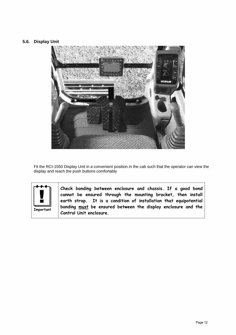
5.6. Display Unit
Fit the RCI-1550 Display Unit in a convenient position in the cab such that the operator can view the display and reach the push buttons comfortably
Check bonding between enclosure and chassis. If a good bond cannot be ensured through the mounting bracket, then install earth strap. It is a condition of installation that equipotential bonding must be ensured between the display enclosure and the Control Unit enclosure.
Page 12

5.7. Control Unit
The Control Unit (CU) contains the termination points for all modules within the RCI-1550 system. It also contains all the user interfaces, signal conditioning and processing circuitry required to satisfy the RCI/LMI functionality. The CU enclosure is a powder coated steel and carries an environmental protection rating of IP 65 which is suitable for internal or external mounting. All cable entries are via a gland plate mounted on the bottom of the enclosure.
Check bonding between enclosure and chassis. If a good bond cannot be ensured through the mounting bracket, then install earth strap. It is a condition of installation that equipotential bonding must be ensured between the display enclosure and the Control Unit enclosure.
5.7.1. Power Supply (PS) Also refer to drawings at the rear of this manual for this item.
The power supply is a 16W, triple output isolated power supply. The input connector has three terminals for each of the supply positive (V+); and supply negative (V-), allowing for looping if required.
The V+ is switched to the output connector via a single pole 5A relay only when the PS is running. The output connector contains two sets of power/RS-485 connections, one being for the display connection and the other for expansion modules. The front panel fuse protects power for this output connector.
The RS-485 signals are electrically isolated from the power and care must be take to ensure that no short circuit is introduced between them, otherwise the unit's transient protection will be compromised.
Transient protection has been included on all inputs. All internal power rails are current limited and short circuit protected using re-settable fuses. These fuses will reset only when the fault has been corrected and the power to the unit has been removed for at least 30 seconds before re-application. There are no operator adjustments or settings on this board.
For complete wiring details refer to the installation drawings.
Page 13

5.7.1.1. Specifications Input supply: 10V - 40V dc @ 8W (max) Input fuse: 5A slow blow User output: Switched V+ when PSU is running (5A max) Internal outputs: 5V @ 500mA (max)
12V @ 500mA (max) 12V (2) @ 500mA (max) All supplies operate with 1mV p-p ripple.
5.7.1.2. Transient protection Common mode to chassis: > 7kV on RS-485 signal, power input and outputs. Differential (line-to-line): > 7kV on RS-485 signal lines
> 2kV on power input and outputs.
Page 14

5.7.2. CPU Section The processor is an 8051 derivative which contains a number of enhancements over the standard 8051, including an on-board 10 bit ADC. For most applications this degree of resolution is more than adequate.
The data memory is in the form of a single package which contains the memory device with real time clock (RTC) and integral lithium battery. This package has guaranteed memory retention of 10 years, and when flat the whole package must be replaced.
The program memory may reside in either a 64kB EPROM or the Expansion EPROM package labelled as U5 (refer to the PCB overlay). When the program has been put into U5, it will be labelled with the application WA number, otherwise it will be labelled with an ID number. When it is labelled with a WA number, there must be no EPROM loaded in location U8 otherwise damage to the processor circuitry will result. The Expansion EPROM package must only be removed using the correct extraction tool otherwise either the package or the socket may be damaged.
The high capacity Flash memory has been added to the 1550 to contain three main blocks of information, being Load-charts, Load Moment (LM) calibration tables and Data-logging. The memory is contained in two plug-in SIMM cards and depending on the application, any number of these may be installed. Refer to the relevant software configuration sheets for more details.
The SIMM cards can only be inserted one way, however care must be take during installation and removal. It is essential that the SIMM cards are installed in the correct sockets and that the correct sequence is followed.
To install a SIMM card, simply push the card into the socket at an angle of approximately 45 degrees (with the components facing toward the centre of the main circuit board). Once the gold pads on the leading edge of the card have entered the socket, gently push the card into the socket while rotating it to a vertical position. Installation is complete when the retaining clips on each end of the socket have captured the edges of the board and have fully returned to their original position.
To remove a SIMM card simply push the retaining clips at each end of the socket outwards until the SIMM card springs away from its vertical position. The card can then be gently withdrawn from the socket.
5.7.2.1. Specifications Processor: 8051 derivative, operating at 18.4320MHz Data Memory: 32kB of battery backed non-volatile SRAM Program Memory: 64kB EPROM for program memory, expandable to 256kB High Capacity Memory: up to 4MB Flash. RS-232: 9600 baud (8N1)RS-485: 19,200 baud. (8N1)On-board ADC: 10 bit PWM output: 8 bit.
5.7.3. Analog Input Section The analog section is takes advantage of the CPU’s on board 10bit ADC. This board can support up to four load cells, three angle sensors and three length sensors.
5.7.3.1. Sensor Excitation Supply The excitation supply provides power for all the sensors connected to the Analog section. The nominal output is 4v (or 12V for 4-20mA transducers). Do not connect either the +VEX or the –VEX outputs to any external supplies or chassis.
5.7.3.2. Load Cell Inputs The analog input section is capable of accepting load cells with sensitivities of 1, 2 or 3mV/V. Load cells of different sensitivities can be used on the one RCI-1550 at the one time. The gain setting is controlled via software.
Page 15
5.7.3.3. Angle Inputs Either oil damped or electronic inclinometers can be connected to the RCI-1550’s angle inputs. Note that all angle sensors must be the same type and may not be mixed. The analog section must be configured, via a single jumper link to accept the appropriate type of sensor. See connection diagram in rear of manual.
5.7.4. Digital IO Section Refer to drawings at the rear of this manual for this item. The DIO section provides general-purpose inputs and output capable of sensing the state of 8 switch inputs and controlling 8 relay outputs. Connection is via plug-in Mini Combicon (R) screw terminals. The DIO section is very versatile and reference should be made to the installation drawings for details. The digital section features LED indicators for input and output status. If the digital section detects an input signal (voltage) the corresponding LED will be illuminated. If an output LED is on then the given output relay is closed.
5.7.4.1. I/O Connections Refer to drawings at the rear of this manual for this item.
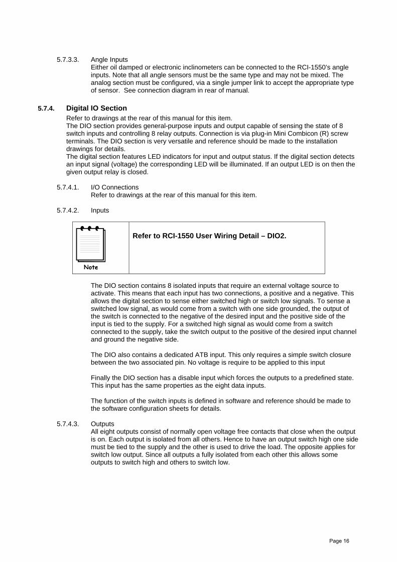
5.7.4.2. Inputs
Refer to RCI-1550 User Wiring Detail – DIO2.
The DIO section contains 8 isolated inputs that require an external voltage source to activate. This means that each input has two connections, a positive and a negative. This allows the digital section to sense either switched high or switch low signals. To sense a switched low signal, as would come from a switch with one side grounded, the output of the switch is connected to the negative of the desired input and the positive side of the input is tied to the supply. For a switched high signal as would come from a switch connected to the supply, take the switch output to the positive of the desired input channel and ground the negative side.
The DIO also contains a dedicated ATB input. This only requires a simple switch closure between the two associated pin. No voltage is require to be applied to this input
Finally the DIO section has a disable input which forces the outputs to a predefined state. This input has the same properties as the eight data inputs.
The function of the switch inputs is defined in software and reference should be made to the software configuration sheets for details.
5.7.4.3. Outputs All eight outputs consist of normally open voltage free contacts that close when the output is on. Each output is isolated from all others. Hence to have an output switch high one side must be tied to the supply and the other is used to drive the load. The opposite applies for switch low output. Since all outputs a fully isolated from each other this allows some outputs to switch high and others to switch low.
Page 16

Note: These outputs are not fuse protected through the RCI-1550, hence the protection must be provided by external means.
5.7.4.4. Snubber diode protection to crane fitted solenoids or relays The use of snubbed inductive loads (ie solenoids and relays) is strongly recommended, however care must be taken to ensure correct polarity connection to these devices.
5.7.4.5. Defining the status of Outputs (normally closed OR open) Provision has been added to the circuit to define the state of each output if there is an on-going fault in the CPU section. The reasoning for this provision is that the user may want one output to fault to an off position (ie Motion Cut) and another to fault to an on position (ie External audible alarm). The status is defined using DIP switch SW1 with the switch position number referring to the respective output. When the switch is “ON”, the corresponding output will be energised if the CPU fails, or alternatively when the switch is “OFF” the corresponding output will be de-energised if the CPU fails. This ‘fault state’ can be selected manually by the user by activating the disable input.
5.7.4.6. Specifications Relay Outputs: 5 ampere @ 30 VDC Switched Inputs: Input current approx. 6mA @ 24V DC
5.7.4.7. Anti-Two Block input Refer to DIO connection drawing in the rear of the manual. Provision has been made on the board for the direct activation of Output 1 via an external switch.
This produces an instantaneous output signal, avoiding the possibility of delays caused by software.
To use this facility, ensure that link P4 is in the “ON” position that allows the CPU to read the status of the switch. The user then has the choice of allowing the CPU to over-ride the condition (ie in Rigging mode) or to leave total control to the external switch. If CPU control is desired, then link P3 must be in the “ON” position, otherwise leave it “OFF”.
If control has been given to the CPU, then the user must ensure that the fault status switch for Output 1 is in the “OFF” position, otherwise in a fault condition the output will be over-ridden. Once this has been set up, the status of the output is defined by the status of the external switch connected as per the wiring detail, with the output relay being energised (ie closed contacts) when the external switch is closed.
5.7.4.8. Slewing Zone Switch/es input/s Fit slewing zone indicator micro-switch (or proximity switch) provided at a convenient place near the centre of rotation providing run on and off ramps as required for the particular application. This switch will convey a signal to the Control Unit when the crane moves into a zone of restricted capacity rating. For correct wiring instruction refer to drawings at the back of this manual.
The switch wiring requires a "voltage free" connection. Never connect the switch wiring into any other system/wiring loom unless the exact nature of the connection is known.
Page 17

5.7.4.9. Motion Cut If motion cut is required the client shall provide appropriate solenoid valves/devices to activate the function and wire them as shown in this manual.
5.7.4.10. Connections
1. Permanent display damage may occur ifincorrect motion-cut connections are made.
2. POWER MUST BE DISCONNECTED beforeattempting connections.
3. NEVER insert larger capacity fuses than thoseoriginally supplied.
4. Obtain specialist assistance if you areunfamiliar with crane electrics.
5. The Robway relay contact ampere rating mustnot be exceeded when directly operating hydraulic or mechanical solenoid devices or high capacity relays. For such devices a “slave” relay must be used.
5.7.4.11. Main & Aux. Winch Hoist Direction Switches (if required) (If required due to high reeving friction differential between hoist raise and lower, usually for greater than 14 parts-of-line)
Fit direction switches provided to control linkage for main and aux hoist functions. Connect switches as shown on drawings in this manual.
The normal convention is that a switch closure should represent a downward hoisting direction.
The switch wiring requires a "voltage free" connection. Never connect the switch wiring into any other system/wiring loom unless the exact nature of the connection is known.
5.8. Upgrading to RCI-1550 from earlier Robway model displays. The RCI-1550 display/controller utilises the same sensors as used on other RCI series systems. However, it is recommended that all earlier version systems used negatively switched motion-cut output signals. The RCI-1550 can be configured for either negative or positive type outputs. Please ensure the preferred arrangement is connected via the digital section connector strips.
Page 18

6. OPERATING INSTRUCTIONS
6.1. The LCD Display
1. Over-ride active indicator 10. Cancel button
2. Audible alarm disabled LED 11. Soft menu buttons: - refer manual
3. Two Block Indicator 12. Alpha-numeric buttons: refer manual
4. Approach to rated capacity LED 13. “Up” button when Menu selected: -see also 18
5. 100% capacity exceeded LED 14. LCD Display: - refer manual
6. Motion Cut activated LED 15. Winch Select Button
7. Bar Graph: - % of rated capacity 16. Tare on/off button
8. Rigging mode button 17. OK or accept button
9. Function Buttons: - refer manual 18. MENU button (also “Down” buttonwhen MENU selected - see 13
1 2 3 4 5 6
7
8
10
13
18
17
9
16
15
14
9
11
12
Page 19

6.1.1. The Bar Graph This is the rectangular bar that is in the top centre of the LCD. This gives an “analogue” indication of the percentage the current load is of the Safe Working Load. The bar will start to grow when the load is 50% of the SWL and reach the amber section at 85%. The start of the red section corresponds to 100% rated capacity.
6.1.2. SWL The displayed S.W.L. is extracted from memorised look-up load-charts and will depend on the current crane configuration, duty, winch selected, the maximum line-pull and the falls selected.
6.1.3. Length This is the current TOTAL boom length as selected from the Crane Duty Listing provided for each System. TOTAL boom length includes any attachment/s as specified by the current crane configuration duty.
6.1.4. Angle This is the current boom angle. This angle will be either the MAIN BOOM, OR the LUFFING FLY (when selected and in use)
6.1.5. Radius Shows the operating radius for the CURRENT CONFIGURATION and DUTY and WINCH selection. The radius is calculated from the Boom Angle and Length sensors with compensation applied to include, slew offset distance, head sheave radius and boom deflection.
6.1.6. Load This shows the current total lifted load for the selected winch. For endless/tandem reeving it will show the total load of both winches. Please note that this load value may contain some TARE value. The TARE lamp being on indicates this (see TARE function later in this section).
Use the WINCH button to switch between #1, # 2 or #3 selection. INVALID WINCH SELECTIONS WILL BE DISABLED IN SOFTWARE.
Although the RCI-1550 will always check safe operation for all winches, you should make sure that the correct winch is selected as the winch selection affects the values shown on the displays. When the ACTUAL LOAD exceeds the SWL for the current crane configuration the RCI-1550 will activate audible and visual alarms.
6.1.6.1. Hook Load selection
MAIN WINCH SELECTED #1 AUX. WINCH SELECTED #2 Main load displayed Main SWL displayed Main falls displayed
Aux. Load displayed
Aux. SWL displayed
Aux. falls displayed
Note: #3 winch selection is reserved for cranes with 3 hook winches.
PROGRAMME REVIEWS AT ALL TIMES
Main load - Main SWL Main line pull Aux. load - Aux. SWL Aux. line pull
Page 20

6.1.7. Error Codes Additionally, the lower area display LCD is used to display ERROR codes when any errors are detected.
Should the operator press the ACK button with an error code number displayed, the text window will revert to normal until a different error condition arises, or the acknowledge timeout expires.
The original error code can be reviewed by simply pressing the ACK key a second time.
Please refer to the ‘Trouble Shooting’ section of this manual for the meaning of the displayed error codes.
6.2. The Display Keypad This section describes the operation of the keypad and the associated LED indicators. Operationally, this window displays the selected crane configuration and provides warning lamps to visually indicate the reason for activation of the audible alarm.
6.2.1. Function Key (F1, F2, F3) These are general-purpose keys that may be assigned a job specific use. Any special functions use will be listed in the appendix.
6.2.2. Soft Menu Keys These are similar to the Function keys in that each one does not have a specific use. Their use can change depending on what state the display is in. The function of each key, if it is actually used at that time, will be listed above it on the bottom line of the LCD. Not all will have assigned uses at any one time. Take careful note of the LCD as their use can change as you navigate through menus. For example the right hand soft menu key is typically used to invoke the menus during normal operating mode. Once the menu is used the two right-hand buttons are used to scroll up and down the menu list.
Refer to the section titled “Menu Navigation” for more information on the functions of each menu
6.2.3. Alpha-Numerical Keys Used for data entry in Calibration mode. When the display is expecting a numerical input the number assigned to each key will be used. If text data is required the first key-press will generate the first letter above the pressed key. If the key is pressed again in quick succession a second time the letter will change to the second above the key and so on. If no key is pressed for approximately 1 second the character on the screen will be accepted as being correct and the display will move to the next character.
6.2.4. Ok () key Used to ‘accept’ the currently displayed message or option on the LCD.
6.2.5. Cancel (x) Key Used in Calibration mode to cancel incorrectly entered data or to escape out of various menus
Page 21

6.2.6. Tare Key The RCI-1550 allows the operator to TARE out the weight of the hook, rope and accessories of the selected winch if required. This is a toggle function that turns on or off depending on its current state and is a function of the currently winch selected.
If the TARE indicator is illuminated then the displayed load is the total weight minus the accessory weight. When TARE is next pressed, the displayed load reverts to the total. If the TARE indicator is off then the actual load shown in the load window at the time of pressing the TARE button will be stored in the system as the tare load.
Please note that when the TARE function is active, the %SWL is still determined by the total load, irrespective of what is currently displayed. All tared weights are removed on system start-up.
6.2.7. Rigging Key Rigging mode is operator selectable via the MENU button and scrolling to Rigging Mode, alternatively the rigging key on the front panel can be used to initiate rigging. There are two forms of Rigging mode. General Rigging mode, where motion-cut is over-ridden (if fitted) to luff down and hook up.
This mode is ONLY intended for use during crane lay-down or setup.
If after this function is initiated, the boom is raised more than 10 degrees, this function will reset to normal crane operation. This is necessary to ensure overall safe crane operation.
Temporary/ATB Rigging mode, which is essentially the same as normal rigging mode withthe exception that it over-rides motion cuts for only a limited period or time. This mode isintended to allow the operator to over-ride the display in special circumstances (eg. need toraise through ATB switch to gain some height etc.).
This operator selectable mode is provided to enable crane hoist rope reeving which wouldotherwise cause alarms and motion-cut (if fitted). When selected, the display automaticallychooses whether full rigging mode or temporary rigging mode is enabled. Full rigging modewill only be enabled when the crane is NOT positioned in a legal lifting position.
Rigging mode will be cancelled when the operator presses the cancel button. If errorsbecome active in rigging mode they will not be displayed but the audible will sound. TheACK button can be used to silence them for approximately 5 minutes (according to thesetting for the Acknowledge Timeout).
If normal crane operation is overridden the LCD will display a message indicating“Temporary Over-Ride” is occurring. The override will end if the operator presses cancel or10 seconds have expired.
If an attempt is made to enter rigging mode but there is a load on the hook which exceedsthe rigging threshold, or the boom length exceeds the rigging length threshold, then amessage stating this will be displayed. The main menu will subsequently be displayed afterapprox. 3 seconds.
ROBWAY recommends that the over-ride key-switch be switched off (ie, normal position) at all times and the over-ride key held by the site-supervisor.
Page 22

6.3. LED Indicators This section describes that operation of the 5 LED indicators that run along the tope edge of the RCI-1550 display.
6.3.1. Override LED The Override Led is illuminated when the Override key switch is activated. Refer to the section on the Override key switch for more information. It is also activated during rigging modes.
6.3.2. Audible Alarm Disabled LED Illuminated when the in cabin alarm has been cancelled. This occurs when the operator presses the ACK soft menu button to acknowledge an error. Acknowledging an error effectively cancels the alarm for that error for a period of time. The amount of time the error will remain acknowledged is determined by the setting for this option. If the Acknowledge Timeout value is set to zero the error will not re-sound unless a new error occurs or the same error re-occurs.
6.3.3. A.T.B. Indicator (anti-two-block or over-hoist) The RCI-1550 can be supplied with an Anti-Two-Block sensor to prevent two-blocking of the main and aux winches. When the A.T.B. indicator on the front panel is lit, a two-blocking condition has occurred and further hoisting may be stopped by activation of the ATB motion cut relay if installed. An audible alarm also sounds a warning. If the Anti-Two-Block system is not required for the given application the two wires normally connected to the two-block sensor/s, should be connected together to avoid erroneous activation of motion cut (refer to the drawing section of this manual).
If in Over-ride OR Rigging mode. During some operations (such as Over-Ride and rigging modes) the ATB LED will flash. This indicates that the ATB circuit has been over-ridden and the RCI unit can not actually sense the state of the ATB condition.
6.3.4. Approach to Rated Capacity LED This is illuminated when 85% of rated capacity is exceeded. This corresponds to the bar graph being in the amber region.
6.3.5. 100% Capacity Exceeded LED This is illuminated when 100% rated capacity has been exceeded. This corresponds to the bar graph being in the red region.
6.3.6. Motion Cut LED This illuminated when the RCI-1550 has activated the motion cut outputs and is preventing the crane from moving into a more hazardous state.
6.4. Over-ride Key-Switch (If fitted) Should crane overload be reached (or other limitations exceeded, such as maximum radius, minimum angle, winch line-pull etc), the system will activate the motion cut relay, if installed. This will then stop further over-loading of the crane. To bypass or temporarily override motion cut, the operator can use the over-ride key which should be held by the site-supervisor. When the key is inserted and turned on, the O/RIDE indicator is illuminated as a reminder.
The Master Over-ride key-switch is located on the Control Box Unit.
Turn on to deactivate motion lock-outs.
Page 23

6.5. Disable Key Switch (If Fitted) The purpose of the disable switch input is to bypass the RCI-1550 should a hardware fault develop. The override input simply signals to the software that if an overload is present to ignore it, hence is software controlled. The disable input is a hardware bypass, and in fact no software need to be running at all. Hence should the main processor fail, the disable input can be used to allow operation of the crane until the unit can be serviced.
Like the override key, this key should be held by the site supervisor.
6.6. Turning on the RCI-1550 Generally by the ignition key-switch OR as installed. Power to the RCI-1550 can be derived from the automotive alternator DC supply, nominally 12V or 24V DC namely; The crane electrical ignition circuit. The crane electrical accessory circuit.
For either DC supply, absolute voltage range is 10 - 40V DC.
As soon as power is applied to the RCI-1550, its display and other indicators should light up and the RCI-1550 should go through its self-test operation.
6.6.1. On Power Up Upon power being supplied, a test pattern is written to the LCD that completely blackens it and all LEDs will be active. After approx. 5 seconds the test pattern will be replaced by Robway information for approx. 3 seconds on the graphical LCD. The message “Please Wait” will then be displayed until communication has been established with the control unit.
The LCD will then display the build information. The operator is required to press the OK button for the display to proceed to the normal operating mode.
The active “Crane Configuration” is then displayed, the operator is required to press the OK button if the crane configuration is correct or the Cancel button if incorrect.
Pressing cancel will allow the operator to change the duty and/or falls ( a ‘PIN’ number may be required to be entered by the operator in order to effect changes). After the crane configuration has been be confirmed the display will proceed to the normal operating mode.
6.7. Menu Navigation During normal operation the soft menu key with the label “Menu” can be pressed. This will cause the lower section of the LCD to display the main menu screen.
By pressing the Up/Down soft menu keys the desired menu item can be selected.
The currently selected menu item is highlighted by a solid bar, pressing the OK key will activate the selected item. The main menu consists of 4 four main sections which are discussed below.
Page 24

6.7.1. Config Change Menu This selection is used when the operator wishes to change some aspect of the crane configuration. Upon selection of this item the “Config Menu” is displayed. The Config Menu typically allows the operator to change the following parameters:
the currently selected duty, the falls (parts of line) for each winch, any special items for a particular job,
It is not possible to change the crane configuration when a lift is being performed. If the current load (on any winch) is greater than or equal to the Lift Threshold value (for the given winch), the Lift in progress screen will be displayed. This inhibits the altering of configuration once a lift has begun. If it is imperative to change the configuration even though a lift is being monitored, it is possible to change the duty and or falls in calibration mode provided you have the correct access code.
When no lift is in progress it is possible to change any of the items that describe the crane configuration.
Selecting to change the duty will cause a series of screens to be displayed prompting the operator to select each aspect of the current crane configuration.
Once editing is complete, pressing the OK button changes the duty according to the selections made, if possible, else a message is displayed informing the operator that there is no duty provided that matches the selections made.
Selecting to change the falls will bring up the falls change screen, provided that no lift is currently in progress. This screen allows the operator to set the currently reeved falls for the currently selected winch.
The falls can be changed by either using the Up/Down keys or by using the numeric buttons. Once editing has been complete, pressing the OK button effects the change to the new edited value. If the cancel button is pressed the edit is discarded and the display returns to the main menu.
6.7.2. Function Codes Refer to the Function listing at the rear of the manual for detailed information on the available function codes.
Page 25

6.7.3. Display Options Menu This menu contains the settings that are specific to the look and “feel” of the display unit itself. Such items include the units displayed, the volume of the buzzer and contrast of the display as well as the setting for the Acknowledge Timeout.
6.7.3.1. Acknowledge Time-Out Sets the time for which the acknowledge soft menu button will silence the in cabin alarm and hide any errors.
6.7.3.2. Display Units This option allows the operator to view information in either metric or imperial units according to personal preference. Selection of the “Change Units” item can be performed at any time (ie. even during a lift).
6.7.3.3. LCD Contrast This allows the operator to adjust the LCD for optimum contrast. The contrast or ratio of black to “white” on the LCD depends on viewing angle and temperature. Temperature compensation is provided in hardware but variations in the individual LCD circuits mean this may not compensate perfectly. Hence the contrast may need to be adjust occasionally. The setting is retained when the unit is turned off. The LCD contrast can also be changed during display start-up by pressing using the rigging button BEFORE the first OK after the unit powers up.
6.7.3.4. Buzzer Volume Allows the operator to set the in cabin audible alarm to an appropriate level. This setting is retained when the RCI-1550 is turned off.
6.8. Data Logging and Data Down-loading Please refer to the Data Logging Manual supplied separately for details.
Page 26

7. CALIBRATION
7.1. Calibration Purpose The monitoring sensors (Load-cells, Boom angle, Boom length etc) require calibration (scaling) so that their output directly relates to the crane.
7.1.1. Entering Calibration Mode and Selecting calibration functions. Make sure that the correct duty number, winch and falls are selected before entering Calibration mode. Verify the correct boom length is displayed.
To enter Calibration mode, press MENU then ARROW to “Function Codes”, press OK. You will be asked to enter a PIN NUMBER to confirm your Robway Training. Enter the correct pin number to gain access to Calibration Function Codes, an incorrect Pin Number will cause only VIEW mode to be accessed.
Once calibration mode is entered use the UP/DOWN keys to ramp through the calibration functions.
Pressing the Cancel button twice will return the system to Operator mode.
7.1.2. Function codes menu item When the Function code item is selected from the main menu, the password entry screen will be displayed. A PIN is required to enter calibration mode.
View - Press OK
Change – key P.I.N
PIN: _
Pressing the Cancel button returns the operator to the main menu.
If view mode is requested the message “View access granted” will be displayed.
If calibration mode is required the operator must enter a PIN and then press the OK button. If the PIN is correct and the controller enters calibration mode then the message “Cal access granted” will be displayed. An incorrect PIN will result in the message “Incorrect Password View access granted” being displayed.
When in calibration or view mode, the function code screen (Diagram 8) is used to select the desired function. The Up/Down data entry buttons or the numeric buttons can be used to scroll through the function codes. Pressing the Cancel button returns the operator to the main menu. By pressing the OK button the display enters the selected function.
Function code
00 Exit Calibration01 View Active Winch02 Cal. Active Winch03 Not Used04 Not Used05 Not Used
Page 27

7.1.3. General information regarding text editing Function codes that require editing will have a blinking cursor indicating where the edit will take place. The numeric buttons are used to enter the new value (unless stated otherwise). The OK button should be pressed when the edit is complete to accept the new value. Pressing the cancel button aborts the edit and any changes made are discarded.
The “. / -“ button can be used to enter a decimal point or a negative value. If a negative number needs to be entered the “. / -“ button should be pressed before any numeric buttons. Pressing the “. / -“ button again before any other numeric button are pressed, results in the “ - “ being removed. If a number contains only a fractional part (ie. 0.123 ) the operator needs to press the button “0” before the “. / -“ button otherwise a “-“ will be displayed.
7.2. Calibration Functions Breakdown
7.2.1. Exit Calibration item Returns the operator to the main menu.
7.2.2. View Main Load and View Aux Load items Displays the Main load
VIEW MAIN LOAD F01:
Load = 100.12
hh:mm
Page 28

7.2.2.1. CAL MAIN LOW and CAL AUX LOW items Allows the main winch and aux winch low load to be calibrated by using the numeric buttons. The current load value is displayed and below it the edited value. Once the edit is complete, pressing OK will result in the Display requesting the controller to do a calibration change. Pressing Cancel at any time will abort the edit and return the operator to the Function codes menu screen.
CAL MAIN LOW F02:
Current = 234.99
Edit = 0.1
hh:mm
7.2.2.2. CAL MAIN HIGH and CAL AUX HIGH items Allows the main winch and aux winch high load to be calibrated by using the numeric buttons. The current load value is displayed and below it the edited value. Once the edit is complete pressing OK will result in the Display request the controller to do a calibration change. Pressing Cancel at any time will abort the edit and return the operator to the Function codes menu screen.
The Graphical LCD will appear similar to CAL MAIN LOW.
7.2.3. View Boom Angle item Displays the calibrated and un-calibrated values.
VIEW BOOM ANGLE F07:
Uncal. = 555
Cal. = 23.22
hh:mm
7.2.3.1. CAL LOW BOOM ANGLE item Allows the low end of the selected item to be calibrated using the numeric buttons. The current raw value and calibrated value are displayed and below it the edited value. Once the edit is complete, pressing OK will result in the Display request the controller to do a calibration change. Pressing Cancel at any time will abort the edit and return the operator to the Function codes menu screen.
CAL LOW B.ANGLE F08:
Uncal. = 555 Cal. = 24.34 Edit = 133.6
hh:mm
7.2.3.2. CAL HIGH BOOM ANGLE item The graphical LCD will appear similar to CAL LOW BOOM ANGLE.
Page 29

7.2.4. View Jib Angle item This function code item is only available for Luffing fly systems. The graphical LCD will appear similar to VIEW BOOM ANGLE.
7.2.4.1. CAL LOW J.ANGLE item This function code item is only available for Luffing fly systems. The graphical LCD will appear similar to CAL LOW B.ANGLE.
7.2.4.2. CAL HIGH JIB ANGLE item This function code item is only available for Luffing fly systems. The graphical LCD will appear similar to CAL LOW B.ANGLE.
7.2.5. Set Gain Trans 1 item This function code allows the transducer gain to be input by software. The numeric buttons “1”, “2” “3” and “4” or the Up/Down buttons can be used to alter the gain for the selected transducer. The graphical will appear as shown:
SET GAIN TRANS 1 F13:
Uncal.: 555 Gain : 2 mV/V
hh:mm
7.2.5.1. VIEW TRANS 1item Allows viewing of the raw, calibrated, and health signal for transducer 1. The graphical LCD will appear as shown:
VIEW TRANS 1 F14:
Uncal. = 555 Health = 500 approx Cal. = 22.11
hh:mm
7.2.6. Set Gain Trans 2 item This function code is exactly the same as the “Set Gain Trans 1” item except it of course operates on the transducer 2 gain.
7.2.6.1. VIEW TRANS 2 item The graphical LCD will appear similar to VIEW TRANS 1 item.
Page 30

7.2.7. Set MUX. Delay item Editing this value alters the multiplexer delay. The multiplexer delay is the settling time ( in ms ) for the analogue hardware. To edit the numeric buttons can be used or the Up/Down buttons.
SET MUX. DELAY F22:
Mux delay : 4
hh:mm
7.2.8. No. of Samples item This menu item is used to stabilise the display in the event that the numbers are changing erratically.
The graphical LCD will show the number of samples currently being used to average the sensor inputs.
This value can be edited by either using the numeric or the Up/Down buttons. If the numeric buttons are used and the value entered is larger than then maximum allowed the message “Max Sample = ” will be displayed.
NO. OF SAMPLES F22:
Samples = 8
hh:mm
7.2.9. Set Lift Value (Threshold) item A lift of a load is said to have commenced when the load is greater than or equal to the lift value. During a load lift it is not possible to change the crane configuration (duty, falls etc.). There is one lift value setting for each winch being monitored. When setting the lift value the load entered should be slightly greater than the weight of the hook block for the winch.
The lift threshold value can be edited by using the numeric buttons. On the graphical LCD both the current lift threshold value and the edited value are shown.
SET LIFT VALUE F23:
Current = 8.23
Edit = 23.12
hh:mm
Page 31

7.2.10. Set Rigging Load Threshold item Rigging the crane often requires that the boom be positioned outside of the normal operating regions of the load chart. It is not generally safe practice for the crane to be placed in such positions however, at times such actions are necessary. The “Rigging Load” value is set by the system installer to allow the crane to be manoeuvred off of the load chart. This value represents the highest load that can be seen by the system during a rigging operation. If the load on either hook (or indeed, the combination of loads) exceeds the setting for this function code then rigging mode is automatically disabled and the display will return to a normal operating mode thus generally causing motion cut to the crane.
Setting this value to 0 will effectively disable the rigging mode operation. Any positive setting for this value will allow rigging mode to be activated as long as the combination of loads does not exceed the setting.
SET RIGGING LOAD F24:
Current = 3.00
Edit = 3.50
hh:mm
The installer must satisfy themselves that any value entered here is in accordance with the crane manufacturer or their agents.
7.2.11. Set Rigging Length Threshold item This item is, once again, used for rigging. The rigging length is the maximum length allowed during rigging operations. If the boom length is less than the “Rigging Length” then the display can be placed in the rigging mode. If rigging mode can’t be entered because of the rigging length threshold a message is shown on the graphical LCD informing the operator. Generally this is only used on telescopic cranes however, in some cases it may also apply to lattice boom scenarios.
7.2.12. View Directions item The Hoist directions for winch 1, 2 and 3 can be viewed (if installed) and the Luff direction of the boom is displayed in this function code ( see diagram 37).
Note 1: N/A represents Not Applicable
Note 2: Stat represents Stationary
Page 32

7.2.13. View Load-Chart item This function code is intended to allow easy viewing of the SWL over the operating range of the crane. This mode should NOT be used to actually monitor a lift, however, it is useful for determining whether a specific load will be tolerated at the desired operating position. The main and auxiliary ( if there is more than one hook ) safe working loads can be viewed. The main and auxiliary radii are also displayed.
VIEW LOADCHART F25:
Main SWL: 34.43 Aux SWL: 23.23 Main Rad.: 32.45 Aux Rad.: 31.13
hh:mm
7.2.14. View Digital I/P item The state of the digital inputs can be viewed on the graphical LCD by using this function code. To determine what a particular digital input signal is being used for in the software, please refer to the “System Configuration Sheets.”
VIEW DIGITAL I/P F26:
IN 1: OFF IN 5: OFF IN 2: ON IN 6: OFF IN 3: OFF IN 7: ON IN 4: OFF IN 8: OFF
Card : 1 hh:mm
7.2.15. Set Date item When changing the date, the graphical LCD will appear as shown in the following diagram. The date displayed is in the ISO format (YYYY-MM-DD). An invalid date will cause an error message to appear.
SET DATE F27:
1998-11-24
YYYY-MM-DD
hh:mm
Page 33

7.2.16. Set Time item When changing the time, the graphical LCD will appear as shown in the following diagram. The time displayed is in the format HH:MM:SS. An invalid time will cause an error message to appear. Note: The seconds can’t be edited and will always be “00”. The seconds will begin incrementing once the OK button is pressed
SET TIME F28:
11:23:00
hh:mm
7.2.16.1. VIEW DATE / TIME item When viewing the date and time, the graphical LCD will appear as shown:
VIEW DATE/TIME F29:
Date: 1998-10-01
Time: 11:22:33
hh:mm
7.2.17. Download Logger item Please refer to the Data Logging Manual supplied separately for details.
7.2.18. View Cal-Data item This function code is for the manual recording of calibration data just in case the calibration is lost or a display needs to be replaced. This is to be used in conjunction with the alter calibration data function code when inputting pre-recorded cal data.
The Cal data item of interest needs to be selected before viewing can occur. This is achieved in a similar method to selecting main menu items (see diagram below).
VIEW CAL-DATA F32:
Angle Length
Radius Amplifier1 Load1(up) Load1(down) hh:mm
Page 34

Once the Cal data item of interest has been selected and OK is pressed the graphical display should be showing the following information.
VIEW CAL-DATA F32:
Raw Lo = 123.0 Raw Hi = 222.0 Cal Lo = 222.23 Cal Hi = 12.99 A = 22.5 B = 33.4 hh:mm
7.2.18.1. ALTER CAL-DATA item The Cal data item of interest needs to be selected before editing can occur. This is achieved in a similar method to selecting main menu items. When the OK button is pressed the following screen should be displayed.
ALTER CAL-DATA F33:
Raw Lo = 123.0 Raw Hi = 222.0 Cal Lo = 222.23 Cal Hi = 12.99
hh:mm
To edit an item, use the Up/Down buttons to move the cursor to the item you wish to edit. Then use the numeric buttons as in previous edits to enter the new values. The Ok button should be pressed to set the new values or use cancel to abort the edit.
Warning, incorrect settings may cause the display to operator incorrectly.
7.2.19. Change Duty item This function code is the same as if change duty was selected from the Config Change menu with the exception that the duty can be changed even if a lift has commenced. This feature is only provided in Calibration mode.
7.2.20. Change Falls item This function code is the same as if change falls was selected from the Config change menu with the exception that the falls can be changed even if a lift has commenced. This feature is only provided in Calibration mode.
7.2.21. Back Up Cal-Table item A backup of the entire calibration data can be made through the use of this function code. The backup is stored on the display and can be used to quickly restore the previous calibration if an incorrect modification to calibration has been made or if calibration is lost/corrupted. Calibration backup should be performed after commissioning, when the system is operating well. On load moment systems a calibration backup will also back up load calibration data. Upon completion, the message screen will indicate the success / failure of this process, as well as that of the calibration data.
Page 35

7.2.22. Restore Cal-Table item The backup calibration data can be restored by using “Restore Cal-Table” function code.
Pressing the OK button will start the restore processes and the LCD will display “Executing …”. The calibration data is copied from backup memory to the calibration data that is used at run time. The success of the calibration backup and the optional backup of load calibration data (LM systems only) will be reported.
If the Cancel button is pressed the restore process will not start and the current calibration data will be retained.
7.2.23. Erase Cal-Table! item
The Display will prompt the operator to press OK if he wishes to erase the Cal Table.
Pressing OK here will clean out the memory system and default back to hard coded software. Any on-site changes made will be lost.
Proceed with extreme caution…
ERASE CAL-TABLE! F39:
To Erase the Cal Table Press OK
hh:mm
i7.2.24. User Variables
ROBWAY stores the load-charts and crane geometry in the memory of the RCI-1550 at the time of manufacture. As this information may very from crane to crane, even if they are of the same model, the RCI-1550 allows the installer to change crane information on site. These user variables include dimensions such as slew-offset, maximum falls for main/aux winches, maximum line-pulls, sheave diameters etc. ( refer to function code listing at the end of this manual )
The actual value of these variables are printed on a configuration sheet which is supplied with the system and a copy of it is also attached to this manual.
To verify or change the current value of any of these user variables follow the procedure below: Enter calibration mode, Select the correct function code from the listing then using the UP/DOWN keys ramp to that
function code and press ENTER, If you want to change the value use the UP/DOWN key to select the new value then press
the ENTER key, If you only want to verify the current value press the CANCEL key when finished viewing, Now you should be back at the F-xx prompt and can continue on with the next operation.
Please note that the value of these variables is very important as they affect the safe operation of the RCI-1550 indicator. Therefore the values of the user variables must be checked and corrected if necessary before proceeding with further calibration or operation.
Page 36

7.2.25. Viewing Errors If errors exist they will automatically be displayed when the display is in normal operating mode (ie. provided no other menu displays are active). The graphical LCD will display an error code followed by a short description.
Pressing the ACK button will temporarily silence the cabin buzzer and hide the error report from the screen. The fact that there are “acknowledged” errors in the system will be indicated by the ACK LED illuminating. Any acknowledged errors will be re-reported after a certain amount of time that can be altered in the Display Option menu. Errors are also re-reported if any new error conditions arise.
Once errors have been acknowledged, they can be re-viewed by simply pressing the acknowledge button once more to “un-acknowledge” the errors.
Errors
101:Angle Sensor 1202:Load Sensor 2301: Angle out of allowed range
hh:mm
7.2.26. Verifying Operation of Sensors
Before you start calibrating the RCI-1550, make sure that the sensors are working correctly and their signals reach the RCI-1550.
The RCI-1550 'sees' the crane and its surroundings through sensors. The signals from these sensors are represented as numbers inside the RCI-1550. The range of possible numbers is 0 to 1023 when an 8 bit analogue to digital converter is used (which is the most common type).
The RCI-1550 allows the user to view both the UNCALIBRATED or the CALIBRATED signal from a given sensor ( refer to function code listing at the back of this manual ).
When viewing the UNCALIBRATED signal from a sensor, make sure the number displayed is less than 999 and is more than 32 as you work the sensor through its working range. This is the correct operating range. Also make sure that the numbers displayed in the window are changing in a nice, smooth manner. If you find that the number is too unstable, that is changes by more than 10, then you should check the connections to the RCI-1550 ( refer to troubleshooting at the end of this manual ).
If the signal is less than 32, suspect a short circuit somewhere on that input channel. Eg. the cable to the RCI-1550 has been crushed and has an internal short circuit in it. Moisture inside the plugs can look like short circuit too.
If the count displayed in the window is more than 1,000, look for an open circuit on that input channel. E.g. disconnected lead. If the sensors check out then you can continue on and start with the calibration procedure. If you find any problems, check the troubleshooting guide at the end of this manual or seek help from your nearest ROBWAY distributor.
Page 37

Please note that while in view mode, that is using either "VIEW UNCALIBRATED ..." or "VIEW CALIBRATED ..." functions, the ENTER key works as a toggle switch to turn that channel ON or OFF. This function allows the user to temporarily turn a sensor off if it is not needed. E.g. if you want to use the main winch only on a twin winch system; normally, if you have not connected the auxiliary sensor up, the RCI-3100 will report an error and activate motion cut. To prevent this you can press the ENTER key, while in "VIEW UNCALIBRATE TRANSDUCER 2 function", to turn the auxiliary channel off.
To turn a channel back on, you have to re-enter the same VIEW UNCALIBRATED... function and press the ENTER key again.
Remember that you must always end a view function by pressing the CANCEL key.
7.3. Tools Required for Calibration To ensure correct calibration, you will require the following; an accurate 100’ measuring tape an accurate boom angle finder tool a Robway RCI simulator tool is recommended a notepad to record results the correct Robway system manual for the crane
Page 38

7.4. Map of Calibration (suggested order) Set date and Time Verify the raw counts stay within 33-999 for full working range of all sensors. Ensure all digital inputs (switched) are wired correctly, incl. ATB. Ensure all digital outputs (switched) are wired correctly. Review all geometry Function code settings for correctness Check / Set the following function codes
No. of Samples (amount of averaging applied to sensor inputs) Set Lift Value (enter a weight slightly larger than the selected winch hook block) Set Rigging Load (enter the maximum allowable load allowed during rigging) Set Rigging Length (enter the maximum boom length allowed during rigging) Set % SWL trip points (nominally set to 85, 100 and 110%) Set Data-logger recording points (if supplied)
Calibrate lo/hi boom angle sensor. Calibrate lo/hi luffing fly angle sensor (if fitted) Calibrate Main winch – main Calibrate Aux winch – aux. Calibrate Load to boom angle friction correction (Line-pull based system only with single sheave
tensiometer at the boom tip) Once happy the system is operating correctly, perform a “Cal-Table Backup” to ensure the
calibration data can be restored if necessary. Use the “View Cal-Data” function code to manually record (pen and paper) the sensor calibration
data as an extra safeguard.
7.5. CALIBRATING BOOM ANGLE
7.5.1. Calibrating a low boom angle Safely luff the boom down to a low angle, eg. 30°, Enter calibration mode and select the correct function code for calibrating low boom angle, Accurately measure the actual boom angle using an angle finder, Use the UP/DOWN keys to ramp the display to the required value then press ENTER to
accept this value.
7.5.2. Calibrating a high boom angle Safely luff the boom up to a high angle, eg. 65°, Enter calibration mode and select the correct function code for calibrating high boom angle, Accurately measure the actual boom angle using an angle finder, Use the UP/DOWN keys to ramp the display to the required value then press ENTER to
accept this value.
Verify that the boom angle is accurately measured, using the VIEW BOOM ANGLE function.
Page 39

7.6. CALIBRATING JIB ANGLE (luffing fly jibs only)
7.6.1. Calibrating low Jib angle Ensure that the angle sensor is mounted on the luffing fly and the cable is connected, Safely luff the jib down to a low angle ( eg. 30° to the horizon ), Enter calibration mode and select the correct function code for calibrating low jib angle, Accurately measure the actual jib angle using an angle finder, Use the UP/DOWN keys to ramp the display to the required value then press ENTER to
accept this value.
7.6.2. Calibrating high Jib angle Safely luff the jib up to a high angle ( eg 65° to the horizon ), Enter calibration mode and select the correct function code for calibrating high jib angle, Accurately measure the actual jib angle using an angle finder, Use the UP/DOWN keys to ramp the display to the required value then press ENTER to
accept this value.
Verify that the jib angle is accurately measured, using the VIEW JIB ANGLE function.
7.7. CALIBRATING TENSIOMETER BASED SYSTEMS
7.7.1. Calibrate the Main Winch with light load. (Ensure the correct winch and falls are selected)
Note: - This procedure assumes that the boom angle and length (for telescopic cranes) has already been calibrated and verified, if not then load calibration will be incorrect.
Select the correct Function code number from the Function code list at the rear of thismanual. Use the up/down arrows to enter the correct weight of the light load.
Enter data to represent the lifted weight for MAIN ROPE LIGHT LOAD. This may be thehook block.
If all is well, proceed to calibrate for a heavy load using the correct function number.
7.7.2. Calibrate the Main Winch with heavy load.
(Known test weight is required) (Where direction switches are employed, both UP & DOWN require calibration) Note: - This procedure assumes that the following have been done, if not then load calibration may be incorrect.
Boom Angle and boom length (for telescopic cranes) has been calibrated and verified, Light load has been calibrated and verified.
Safely lift a heavy load and hold just above the ground and enter calibration mode. (at least75% of line-pull is suggested for best results)
Select the correct Function code number from the Function code list at the rear of thismanual. Use the up/down arrows to enter the correct numerical data.
Enter data to represent the lifted weight for MAIN ROPE HEAVY LOAD. If the crane hasan Aux. winch fitted and has been included in the RCI-1502 load charts, proceed tocalibrate the Aux. winch in the same manner as for the Main winch.
Page 40
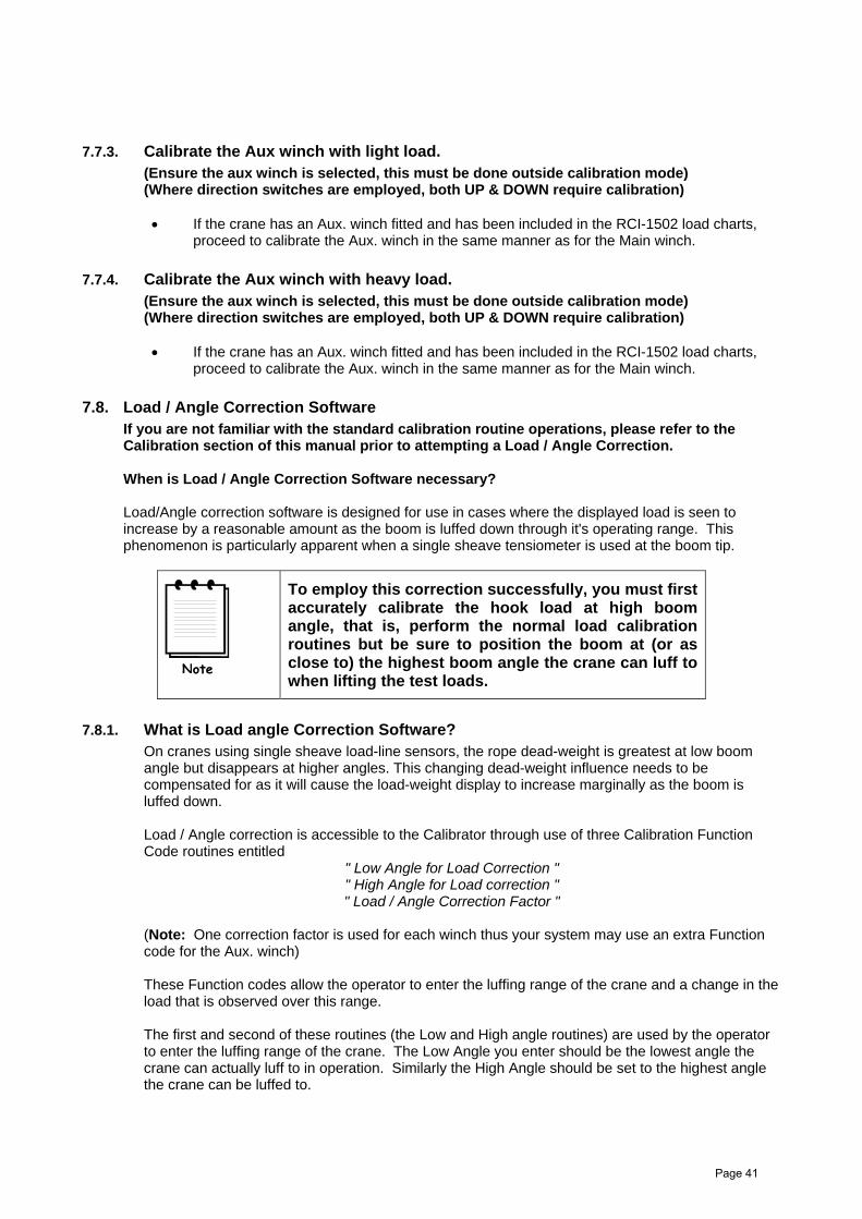
7.7.3. Calibrate the Aux winch with light load. (Ensure the aux winch is selected, this must be done outside calibration mode) (Where direction switches are employed, both UP & DOWN require calibration)
If the crane has an Aux. winch fitted and has been included in the RCI-1502 load charts,proceed to calibrate the Aux. winch in the same manner as for the Main winch.
7.7.4. Calibrate the Aux winch with heavy load. (Ensure the aux winch is selected, this must be done outside calibration mode) (Where direction switches are employed, both UP & DOWN require calibration)
If the crane has an Aux. winch fitted and has been included in the RCI-1502 load charts,proceed to calibrate the Aux. winch in the same manner as for the Main winch.
7.8. Load / Angle Correction Software If you are not familiar with the standard calibration routine operations, please refer to the Calibration section of this manual prior to attempting a Load / Angle Correction.
When is Load / Angle Correction Software necessary?
Load/Angle correction software is designed for use in cases where the displayed load is seen to increase by a reasonable amount as the boom is luffed down through it's operating range. This phenomenon is particularly apparent when a single sheave tensiometer is used at the boom tip.
To employ this correction successfully, you must first accurately calibrate the hook load at high boom angle, that is, perform the normal load calibration routines but be sure to position the boom at (or as close to) the highest boom angle the crane can luff to when lifting the test loads.
7.8.1. What is Load angle Correction Software? On cranes using single sheave load-line sensors, the rope dead-weight is greatest at low boom angle but disappears at higher angles. This changing dead-weight influence needs to be compensated for as it will cause the load-weight display to increase marginally as the boom is luffed down.
Load / Angle correction is accessible to the Calibrator through use of three Calibration Function Code routines entitled
" Low Angle for Load Correction " " High Angle for Load correction " " Load / Angle Correction Factor "
(Note: One correction factor is used for each winch thus your system may use an extra Function code for the Aux. winch)
These Function codes allow the operator to enter the luffing range of the crane and a change in the load that is observed over this range.
The first and second of these routines (the Low and High angle routines) are used by the operator to enter the luffing range of the crane. The Low Angle you enter should be the lowest angle the crane can actually luff to in operation. Similarly the High Angle should be set to the highest angle the crane can be luffed to.
Page 41

7.8.2. How to calculate the Load / Angle Correction Factor The number entered here is a correction value, when this number is 0.0 no correction is being applied (ie. Load / Angle correction is disabled). It expresses the load error (in tonnes) seen when the crane is luffed from the highest angle in the luff range to the lowest angle. This correction is applied progressively from the highest boom angle through to the lowest boom angle.
To determine the error value simply position the boom at the highest boom angle and take note of the load reading. Luff the boom through the entire operating range (taking notice the load value is increasing when luffing lower) and once at the lowest possible boom angle record the load value again. The correction factor is simply the difference between the two load values you have recorded.
Enter the correction value against the appropriate Function Code and luff the crane through it's operating range once again to ensure the correction was successful.
Example: A test weight of 20 t is lifted at the highest possible boom angle (note: it is not necessary to
use a test weight, the hook block alone will suffice for the test). The 20t load is luffed through the entire angle range and the displayed load is seen to rise
to 25.3 t at the lowest possible boom angle The error in this reading is the highest displayed load minus the known test weight ie. 25.3 t
- 20.0 t = 5.3 t error. Hence, in this example, the Load / Angle Correction Factor should be entered as 5.3 t
Page 42

8. MAINTENANCEWhen maintenance is to be performed on the RCI-1550 system, care must be taken to ensure that thelevel of safety is not reduced. Such a reduction in the level of safety can easily be done by thecareless use of tools or test equipment, either directly or by damage to safety components, wiring orclearances. Therefore it is essential that maintenance be performed by competent personnel only.The following are recommendations from the standard on maintenance procedures.
8.1. Check List It is recommended that a checklist similar to the one below be prepared prior to maintenance.
Maintenance Checklist Pre-maintenance Necessary documents are available
All records have been examined. Test gear is available and is satisfactory for use in hazardous areas if applicable. Permission to commence work has been granted. The area is safe to work. Any necessary precautions have been taken.
Maintenance All re-connections have been made. Equipment is functional. Malfunctions have been reported. Installation conforms to drawings and documentation. Any modifications have been approved. Earthing requirements are still valid. General check in accordance with an Inspection and Test Schedule completed.
Post-maintenance Documentation is completed and filed. Inspection report is complete. Company and operator requirements have been satisfied.
8.2. In-cabin items Ensure the display unit mounting is solid and vibration free and that the display cable connection is firmly connected. Ensure the display cable is not pinched or caught or may become suspect to damage on route from the Display Unit to the Controller Unit outside the cabin.
A water dampened cloth is preferred for cleaning general dirt items from the display. Wipe off any build-up of grease and oils. A light mixture of detergent may be used to remove stubborn stains. DO NOT USE SOLVENTS.
8.2.1. Additional detail The RCI-1550 Display case is made of Stainless Steel - Grade 316 and powder coated with high quality DULUX powder coat. High adhesion between metal surface and powder layer ensures excellent resistance to scratches and similar mechanical damages.
Powder coat has increased resistance to chemical agents and UV light. The Stainless steel case ensures resistance to even most aggressive environments such as offshore installations or chemical plants, even when the paint layer is damaged The unit as whole, is designed to comply with the latest EMI and ESD standards.
The front membrane switch panel is made from tough high quality textured polyester film. It offers enhanced chemical resistance and dramatically improved flex life (>5 million switch cycles).
The Acrylic layer is made of CHEMCAST. Acrylic sheet can be used up to 90 °C. It should be cleaned only with household grade detergents or methyl alcohol (30%).
The unit as whole could be used in very hostile environment in temperature range –20 °C to +70 °C
Page 43

8.3. ELECTRICAL EQUIPMENT When any electrical equipment is removed for maintenance, any exposed conductors that remain must be mechanically and electrically secured in a manner to prevent the occurrence of an unsafe condition.
8.4. INSPECTION AFTER MAINTENANCE Robway consider it essential by that a detailed Inspection is performed following any maintenance to ensure that the equipment and installation continue to comply with the documentation. Any deviations to supplied documentation should be updated to inform any future service attendance.
8.5. RECORDS Any details of defects found should be recorded in the crane log book.
Page 44

9. TROULBELSHOOTINGA trouble-shooting or fault-finding section is always a difficult document to write because things that are obvious to one person can be anything but obvious to another. One the other hand, most times when you read such a guide the fault you are trying to solve happens to be the very fault that has been left out! The main purpose of this section is to help both us at Robway and you the reader to find the problem and solve it quickly. Some times this takes patience, which isn’t always easy when are you on the site, your customer is angry because you haven’t fixed it yet, and the Robway guy at the other end of the phone wants you to tell him all over again what you just did!! What we have found many times is that when a situation is described by the service person a couple of times extra details come out in the conversation that are vital to solving the problem. It seems that the more trouble we have finding the faults, the more simple the cause was!
The RCI-1550 system incorporates a number of software features that are designed to help the service person quick identify a fault, however it must be stressed that these features cannot identify everything. They can only be used as a guide to identify additional checks that can be made. Some notes are provided below, followed by some example faults and possible causes.
Identify the symptoms. Take time to find out exactly what is happening to indicate a problem. If possible have the problem demonstrated so you can “describe it in your own words”. Sometimes what someone else has told you is only part of the story.
Leave the calibration alone! Too many times a re-calibration has been attempted in order to rectify a problem before that problem has been correctly identified. This leads to added confusion as the perspective is generally moved from the real fault to “calibration problems’. We have often received a message indicating that our display has “not accepted the calibration data”. Most times this is due to a fault in a cable or sensor which was not identified prior to re-calibration. Re-calibration must only be performed when all physical inputs have been verified for correct operation, and in actual fact is rarely ever needed.
Do you have your simulator with you? A simulator is a very quick way to verify if the fault is external to the display and will save you a lot of heartache. A simulator is purely resistive and hence considered simple apparatus and can be used freely in a hazardous area.
Have you read the manual! When all else fails, read the manual! Your answer may actually be in there.
Know what information you need to gather. If you collect the correct information from the display the job is half done. Before you begin to suspect faults with the system, you must satisfy yourself that the display is correctly configured for the crane environment. In other words, check that the correct duty, falls, slew zone etc. have been selected. Are all of the sensors connected? In general if sensors have been supplied with the system, they must always be connected. The display will check them continuously and issue an error if that sensor cannot be detected. Check your length, angle and radius against the chart to verify that the equipment is permitted to be in that situation. If there is still a problem once these have been checked, then you will need to check the hardware.
The main pieces of useful information obtainable from the displays are the raw counts. The raw counts shows what the actual inputs are doing (ie. like a signal strength indication). These raw counts are manipulated in software according to the calibration data stored in the display to produce the readouts on the Display Unit. If the calibration has been done incorrectly, or the configuration is incorrect, or something else is wrong, then the Display Unit readouts (eg. The LOAD or ANGLE values) may provide you with misleading information.
YOU MUST USE THE “VIEW” FUNCTION CODES TO DETERMINE THE CORRECT OPERATION OF THE EXTERNAL SENSORS.
For correct operation the “raw signal” values must be in the range 33 to 999. Anything outside of this range will produce an error. Refer to the manual for how to access these raw counts.
Page 45

Check the obvious. Once you have found a problem with a sensor for example, check all of the obvious things to do with that sensor such as making sure all of the connectors are tight. Be systematic – make notes about what you have done and what you found. You will find that under pressure you can easily forget what you have checked and it becomes very easy to miss things.
9.1. Error Code List
9.1.1. Example Errors & Possible Causes
Code Description on LCD Fault Description
101 Angle Sensor 1 Sensor is open or short circuit
102 Angle Sensor 2 Sensor is open or short circuit
104 Angle Sensor 3 Sensor is open or short circuit
108 Angle Sensor 4 Sensor is open or short circuit
201 Load Sensor 1 Sensor is open or short circuit
202 Load Sensor 2 Sensor is open or short circuit
204 Load Sensor 3 Sensor is open or short circuit
208 Load Sensor 4 Sensor is open or short circuit
210 Digital Input Digital input error detected
220 ATB Crane is two-blocking
240 Overload Current load exceeds safe working load
280 Linepull Current load exceeds line pull
301 Angle out of allowed range Angle is off the load chart or limit is exceeded
304 Radius out of allowed range Radius is off the load chart or limit is exceeded
308 Height out of allowed range Height is off the load chart or limit is exceeded
310 Slew out of allowed range Crane has been positioned in a non-lifting area
Page 46
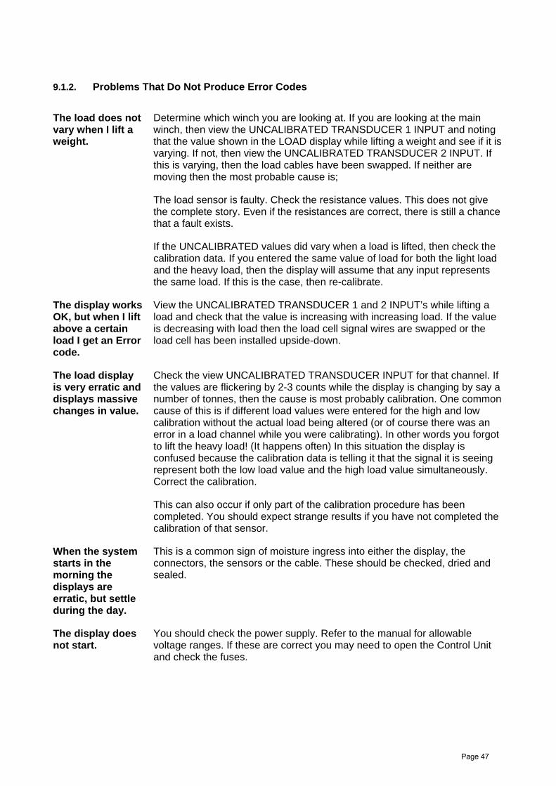
9.1.2. Problems That Do Not Produce Error Codes
The load does not vary when I lift a weight.
Determine which winch you are looking at. If you are looking at the main winch, then view the UNCALIBRATED TRANSDUCER 1 INPUT and noting that the value shown in the LOAD display while lifting a weight and see if it is varying. If not, then view the UNCALIBRATED TRANSDUCER 2 INPUT. If this is varying, then the load cables have been swapped. If neither are moving then the most probable cause is;
The load sensor is faulty. Check the resistance values. This does not give the complete story. Even if the resistances are correct, there is still a chance that a fault exists.
If the UNCALIBRATED values did vary when a load is lifted, then check the calibration data. If you entered the same value of load for both the light load and the heavy load, then the display will assume that any input represents the same load. If this is the case, then re-calibrate.
The display works OK, but when I lift above a certain load I get an Error code.
View the UNCALIBRATED TRANSDUCER 1 and 2 INPUT’s while lifting a load and check that the value is increasing with increasing load. If the value is decreasing with load then the load cell signal wires are swapped or the load cell has been installed upside-down.
The load display is very erratic and displays massive changes in value.
Check the view UNCALIBRATED TRANSDUCER INPUT for that channel. If the values are flickering by 2-3 counts while the display is changing by say a number of tonnes, then the cause is most probably calibration. One common cause of this is if different load values were entered for the high and low calibration without the actual load being altered (or of course there was an error in a load channel while you were calibrating). In other words you forgot to lift the heavy load! (It happens often) In this situation the display is confused because the calibration data is telling it that the signal it is seeing represent both the low load value and the high load value simultaneously. Correct the calibration.
This can also occur if only part of the calibration procedure has been completed. You should expect strange results if you have not completed the calibration of that sensor.
When the system starts in the morning the displays are erratic, but settle during the day.
This is a common sign of moisture ingress into either the display, the connectors, the sensors or the cable. These should be checked, dried and sealed.
The display does not start.
You should check the power supply. Refer to the manual for allowable voltage ranges. If these are correct you may need to open the Control Unit and check the fuses.
Page 47


10. ELECTRICAL SPECIFICATIONS
Controller Automotive alternator DC supply, nominally 12V or 24V DC.
Power Consumption Approximately 20VA (Watts).
Operating Temperature Range
-20C to +60C tested to (-30C to + 70C)
Expected Resistance Values
Load Cells Should have the following nominal resistance values, for a standard 350 ohm cell (note that these values may vary slightly from cell to cell). RED-BLACK 400 ohmsRED-GREEN 290 ohmsRED - WHITE 290 ohms BLACK-GREEN 290 ohms BLACK-WHITE 290 ohms WHITE-GREEN 350 ohms SHIELD to any other wire must be open circuit
Oil Dampened Angle Sensor (When Used)
Across the excitation wires: 1k or 5k ohms Between the signal and each of the excitation wires varying between 0 and 1k or 5k ohms between any of the wires and chassis or shield high ohms, or open circuit
Electronic Angle Sensor
Between any of the wires and chassis or shield high ohms, or open circuit
Length Sensor Across the excitation wires: 500 ohms Between the signal and each of the excitation wires varying between 0 and 500 ohmsBetween any of the wires and chassis or shield high ohms, or open circuit
Voltage Levels Load cell excitation 4.0V Angle excitation 4.0V Length excitation 4.0V Between the chassis and shield 0V
11. Electronic Angle Sensor Specifications:Total range: 120 deg Linear range: 90 deg Threshold and resolution: 0.001 deg Linearity: +/- 1% of angle Null repeatability: 0.05 deg Operating Temperature range: -40C – 65C Temperature coefficient – null: 0.008 deg/C scale: 0.1%/C
Page 48


12.1 Drawings Part A - System Components
Page 50

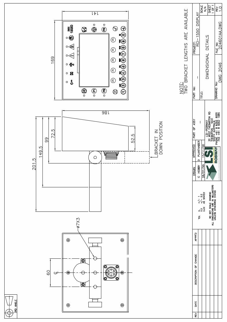


UNCO
NTRO
LLED
COPY
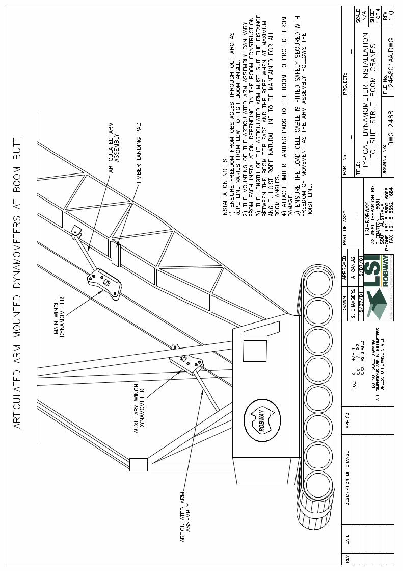

UNCONTROLLED
COPY


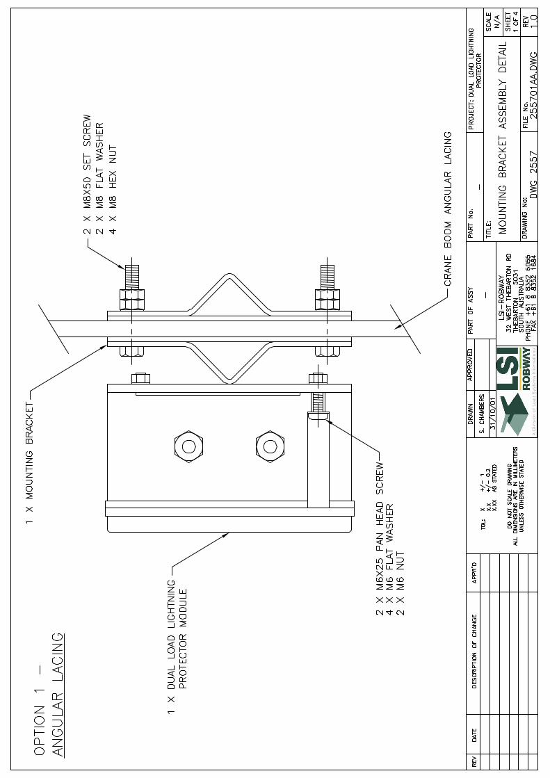

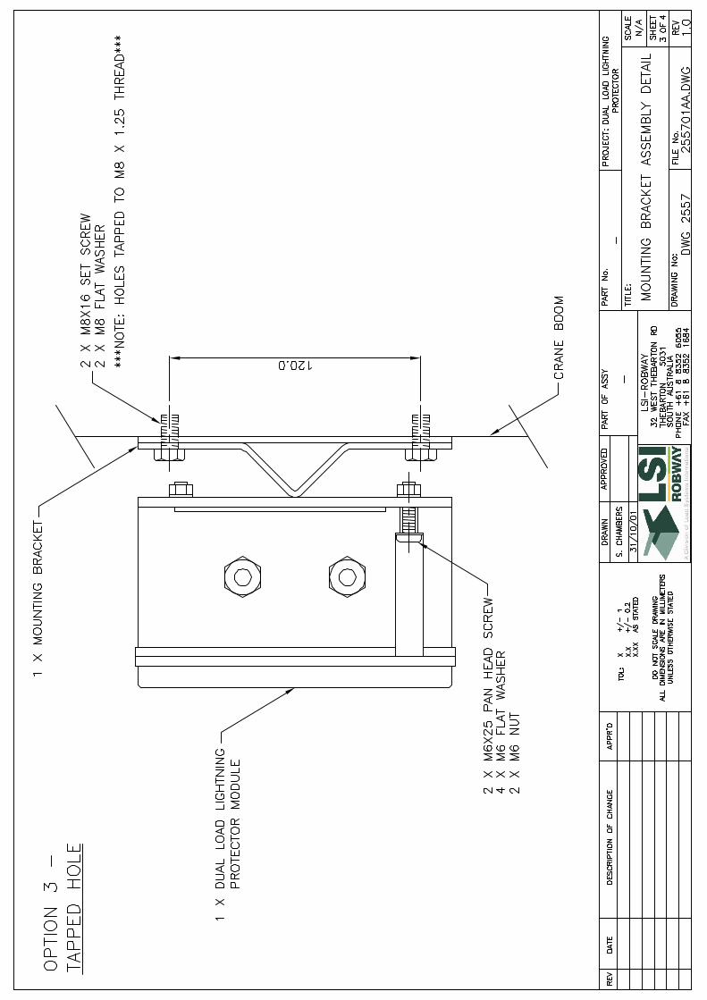
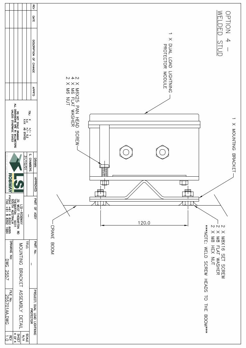


RE
VD
AT
ED
ES
CR
IPTIO
N O
F C
HA
NG
EA
PP
RV
'DD
RA
WN
BY
AP
PR
OV
ED
BY
PA
RT O
F AS
SY
PA
RT N
o:P
RO
JEC
T:
TITLE:
SC
ALE
SH
EE
T
RE
VFILE
No:
DR
AW
ING
No:
OF
web : w
ww
.lsirobway.com
.au
32 West Thebarton R
dT
HE
BA
RTO
NS
OU
TH A
US
TRA
LIA 5031
PH
ON
E: +61 8 8238 3500
FAX
: +61 8 8352 1684 c copyright robw
ay 2005
X.
X.X
X.X
X
TOL:
+/-1+/-0.2+/-0.02
DO
NO
T SC
ALE
DR
AW
ING
ALL D
IME
NS
ION
S A
RE
IN M
ILLIME
TE
RS
UN
LES
S O
THE
RW
ISE
ST
ATE
D
N/A
S. C
HA
MB
ER
S
19/04/2005
1.3293401A
D.idw
AS
SY
, BB
5 DIM
EN
SIO
NA
L DE
TA
IL
SW
IBB
5B
B5 A
TB S
WITC
H
1 2
2934
A. C
AN
LAS
19/04/2005-
3RD
AN
GLE
1.116/07/10
EX
PLO
RE
D V
IEW
AD
DE
D R
EFE
R P
CR
#322A
.A.
1.214/01/2011
RE
FER
TO P
CR
#366A
.A.
1.324-1-14
RE
FER
TO E
CN
543J.H
Parts List
ITEM
QTY
DE
SC
RIP
TIO
ND
WG
No.
PA
RT N
UM
BE
R18
2C
AB
LE TIE
S
TIE200B
K
40�60
40
�9 TH
RU
2 X
4 CO
RE
S
CR
EE
NE
D C
AB
LE
12
22
6
45
257
54
RXXXXXXX
EN
GR
AV
E S
ER
IEL N
O. H
ER
E
AD
D 2 C
AB
LE TIE
S T
O
HO
LD S
PR
ING
IN P
LAC
E
18