Embed Size (px)
Citation preview
8/8/2019 Ravi Main Pages7
http://slidepdf.com/reader/full/ravi-main-pages7 1/15
1
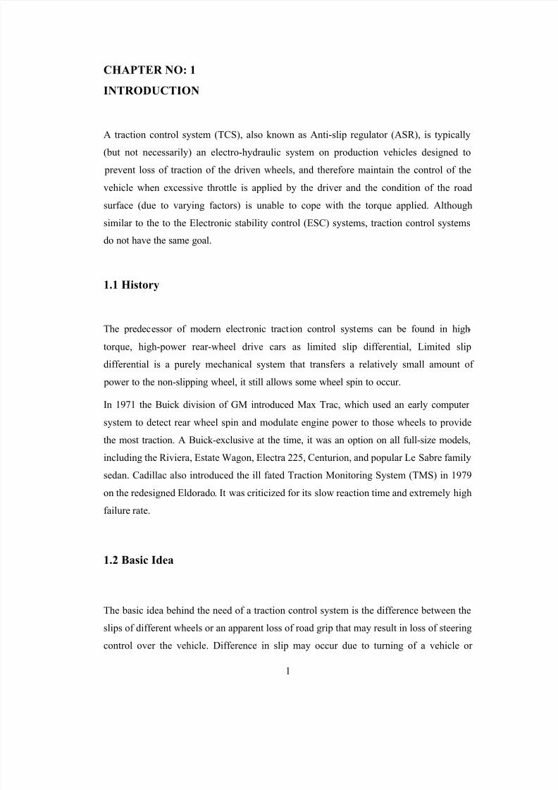
CHAPTER NO: 1
INTRODUCTION
A traction control system (TCS), also known as Anti-slip regulator (ASR), is typically(but not necessarily) an electro-hydraulic system on production vehicles designed to
prevent loss of traction of the driven wheels, and therefore maintain the control of the
vehicle when excessive throttle is applied by the driver and the condition of the road
surface (due to varying factors) is unable to cope with the torque applied. Although
similar to the to the Electronic stability control (ESC) systems, traction control systems
do not have the same goal.
1.1 History
The predecessor of modern electronic traction control systems can be found in high-
torque, high-power rear-wheel drive cars as limited slip differential, Limited slip
differential is a purely mechanical system that transfers a relatively small amount of
power to the non-slipping wheel, it still allows some wheel spin to occur.
In 1971 the Buick division of GM introduced Max Trac, which used an early computer
system to detect rear wheel spin and modulate engine power to those wheels to provide
the most traction. A Buick-exclusive at the time, it was an option on all full-size models,
including the Riviera, Estate Wagon, Electra 225, Centurion, and popular Le Sabre family
sedan. Cadillac also introduced the ill fated Traction Monitoring System (TMS) in 1979
on the redesigned Eldorado. It was criticized for its slow reaction time and extremely high
failure rate.
1.2 Basic Idea
The basic idea behind the need of a traction control system is the difference between the
slips of different wheels or an apparent loss of road grip that may result in loss of steering
control over the vehicle. Difference in slip may occur due to turning of a vehicle or

8/8/2019 Ravi Main Pages7
http://slidepdf.com/reader/full/ravi-main-pages7 2/15
2
differently varying road conditions for different wheels. At high speeds, when a car tends
to turn, its outer and inner wheels are subjected to different speed of rotation that is
conventionally controlled by using a differential. A further enhancement of the
differential is to employ an active differential that can vary the amount of power being
delivered to outer and inner wheels according to the need (for example, if, while turning
right, outward slip (equivalently saying, 'yaw') is sensed, active differential may deliver
more power to the outer wheel, so as to minimize the yaw (that is basically the degree to
which the front and rear wheels of a car are out of line.) Active-differential, in turn, is
controlled by an assembly of electromechanical sensors collaborating with a traction
control unit. The graph 1.1 shown below shows a typical curve which determines the slip
ratios for different surfaces here the slip ratio varies according to the coefficient of
friction. Here it is observed that as the coefficient of friction increases the slip-ratio also
decreases up to a certain limit then afterwards it remains nearly constant afterwards.
Graph 1.1 Coefficient of friction v/s slip ratio

8/8/2019 Ravi Main Pages7
http://slidepdf.com/reader/full/ravi-main-pages7 3/15
3
1.3 Methods of traction control system
y B speed cont ol of t e wheels
1. B cutting the fuel in jector¶s
2.
B appl ing brakes through TR C B ECU y R etard or suppress the spark in the cylinders
y To reduce the fuel supply in the combustion chambers
y In case of turbocharged vehicles reducing the power by activating Boost control
solenoid valve.
y Electronic Throttle control of the engine
Traction controlsystems
Wheel sped type
control systems
Engine type
control system
Mission type (yaw rate
control Method)

8/8/2019 Ravi Main Pages7
http://slidepdf.com/reader/full/ravi-main-pages7 4/15
4
CHAPTER NO: 2
CUTTING FUEL INJECTOR¶S
In this type the traction control is completed by joint efforts of the ABS-TRAC EC &
ECM when the slip occurs the slip of the wheel is detected by the ECM and one of the
cylinders is cut-off by cutting of the injector ultimately reducing the total power produced
by the engine. Once the slippage of the wheels stops then the, the cut-off injector is again
activated, thus the engine again starts producing maximum power.
2.1 Components of the ³fuel injector type system´
a) Wheel speed sensors
b) TRAC pump
c) Solenoid valves
d) TRAC actuator
2.2 Operation
The operation of ³cutting the fuel injector´ type of system is carried out by the ECM of
the automobile. When the speed of the wheels increases the control starting speed then
the wheel speed sensors senses it & sends signals to the ECM, the ECM cuts-off few
injectors, when the speed of the wheel decreases some of the injectors are again
connected, only some injectors are connected to avoid overshooting of the wheel speed
then once the control speed is attained then finally all the injectors are connected to the
engine, thus the engine starts producing maximum power. This is the most simplest of the
all traction control systems, the biggest disadvantage of this kind of control system is that
this system can only be implemented in case of more than 5 cylinder engines.

8/8/2019 Ravi Main Pages7
http://slidepdf.com/reader/full/ravi-main-pages7 5/15
5
CHAPTER NO: 3
BY APPLYING BRAKES THROUGH ABS-TRAC ECU
The ABS/TRAC EC work together, the wheel speed sensor senses the wheel speed
ultimately the speed of the vehicle, then the EC controls the brake of the automobile
ultimately the speed of the engine.
3.1 Components of ³Brake type speed control Traction control unit´
y Solenoid valves 12nos. (2 Master cut-off , 2 Reservoir cut-off, 8 Pressure
regulator)
y TRAC pump
y TRAC actuator
y TRAC EC (electronic control module)
y Wheel speed sensors
y Display unit
3.2 Operation
There are modes of operation in a ³brake type wheel speed control system´ they are as
follows
1. Normal mode of operation
2. Pressure increase mode
3. Pressure holding mode
4. Pressure reduction mode.

8/8/2019 Ravi Main Pages7
http://slidepdf.com/reader/full/ravi-main-pages7 6/15
6
3.2.1Normal mode of operation: When the traction control system is not activated
at all actuator valves are OFF. The Master cut solenoid valve is open allowing the fluid
from master cylinder to flow to the pressure holding valve to the brake cylinder. In this
type the brake just works as that of the system without ABS/TRAC.
(Refer Figure No.3.1)
Table no: 3.1 Normal mode of operation
Part Name Signal from
ABS&TRAC ECU
Operation
Master Cut solenoid Valve OFF Port B Open
Reservoir Cut Solenoid Valve OFF Port H Closed
Pressure Holding Mode OFF Port C Open
Pressure Reduction Valve OFF Port F Closed
Pump OFF Stop
3.2.2 Pressure increase mode: During sudden acceleration or driving on slippery
roads, if the drive wheel suddenly starts to slip the ABS/TRAC EC forces the TRAC
actuator to go into pressure increase mode. The Master solenoid is ON blocking the brakecircuit to the Master cylinder, the reservoir solenoid is open connecting the Master
cylinder to the TRAC pump, the pump is turned ON thus increasing the brake fluid
pressure the pump is connected to the pressure holding valve then to the brake cylinder.
(Refer Figure No. 3.2)
Table no: 3.2 Pressure increase mode
Part Name Signal from
ABS&TRAC ECU
Operation
Master Cut Solenoid valve ON Port B Closed
Reservoir Cut Solenoid Valve ON Port H Open
Pressure Holding Valve OFF Port C Open
Pressure Reduction Valve OFF Port F Closed
Pump ON Rotating

8/8/2019 Ravi Main Pages7
http://slidepdf.com/reader/full/ravi-main-pages7 7/15
7
3.2.3 Pressure holding mode: When fluid pressure in the wheel cylinder circuit is
optimized by an increase or decrease in pressure, the ABS/TRAC EC controls the
system as follows, the pressure holding valve is turned ON blocking the pressure from the
pump, the reservoir cut solenoid valve is turned OFF blocking additional fluid from the
reservoir, though the pumps keeps rotating.
(Refer Figure No. 3.3)
Table No: 3.3 Pressure holding Mode
Part Name Signal From ABS
TRAC ECU
Operation
Master Cut Solenoid Valve ON Port B Closed
Reservoir Cut Solenoid Valve OFF Port H Closed
Pressure Holding Valve ON Port C Closed
Pressure reduction valve OFF Port F Closed
Pump ON Rotating
3.2.4 Pressure reduction mode: When the fluid pressure inside the cylinder is to be
reduced, Reservoir solenoid is turned OFF and the spring loaded valve is kept in theclosed position blocking the fluid from the master cylinder to the pump, Master is cut
from the brake cylinder by turning on the Master cut solenoid valve, the pressure
reduction valve is turned ON, hence reducing the pressure of the brake fluid entering the
brake cylinder.
(Refer Figure No. 3.4)
Table No:3.4 Pressure Reduction Mode
Part Name Signal from ABS &
TRAC ECU
Operation
Master Cut Solenoid Valve ON Port B Closed
Reservoir Cut Solenoid Valve OFF Port H Closed
Pressure Holding Valve ON Port C Closed
Pressure Reduction Valve ON Port F Open
Pump ON Rotating
8/8/2019 Ravi Main Pages7
http://slidepdf.com/reader/full/ravi-main-pages7 8/15
8
CHAPTER NO: 4
THROTTLE VALVE CONTROL SYSTEM
This system is similar to the speed control system the differences are that in this a sub-
throttle actuator is used in front of the throttle valve to control the torque produced by the
engine & there is no brake actuator present in this system.
4.1 Components of ³Throttle valve control traction control system´
y Sub-throttle valve motor
y Sub-throttle position sensor
y Throttle valve
y Acceleration Position sensor
y TRAC ECM (electronic control module)
(Refer Figure No.4.1)
4.2 Operation:
As the accelerator pedal is pressed & when the wheel speed is below 40km/hr the
Acceleration sensor sends signal to the ECM, Whereas simultaneously the Throttle
position sensor sends electronic signals regarding the current position of the throttle
valve, The ECM evaluates the signals received from the sensors and decides the new
required position of the throttle valve and sends signals to the throttle motor to control the
throttle position accordingly. When the slip-ratio is again slowly coming back within the
tolerable limits then the throttle valve is again gradually opened by EC & finally when
there is no slip then the throttle valve operates normally. This kind of system is very
useful in Electric vehicles.
This system is the most widely used system of all the different types of traction
control systems.
(Refer Figure No.4.2)
8/8/2019 Ravi Main Pages7
http://slidepdf.com/reader/full/ravi-main-pages7 9/15
9
4.3 Fail safe operation
The Electronic Throttle Control System has multiple built-in fail-safes and diagnostic
capabilities. If the Electronic Throttle Control System detects a malfunction, the ECM is programmed to initiate a fail safe mode. The following are some examples:
1. If one Accelerator Position Sensor fails, the ECM will illuminate the ³Check
Engine´ light, store diagnostic service information, and limit throttle opening to
about ¼, allowing the vehicle to be driven at reduced power.
2. If both Accelerator Position Sensors fail, or if one Throttle Position Sensor fails,
the ECM will Illuminate the ³Check Engine´ light, store diagnostic service
information and cut power to the throttle, returning the engine to idle speed.
3. If the Throttle Valve binds, the ECM will Illuminate the ³Check Engine´ light,
store diagnostic service information and shut the engine off.

8/8/2019 Ravi Main Pages7
http://slidepdf.com/reader/full/ravi-main-pages7 10/15
10
CHAPTER NO: 5
MISSION TYPE CONTROL SYSTEMS
The mission type control system is a type of traction control system in which the torque
of the slipping wheel is transferred to the non-slipping wheel. Here this is achieved by
braking one of the wheels and simultaneously accelerating other wheel, this kind of
system is very efficient in controlling the yaw-rate, thus can be very effectively used for
avoiding accidents occurring due to slippage of wheels due to under steering or over
steering of wheels at high speeds due to a sudden obstacle on the road. This type of
system is often also known as ESP (electronic stability program) OR ESC (electronic
stability control). Different manufacturers use different nomenclatures to designate this
system, but the functioning of the system is basically the same.
5.1 Components of Mission type Traction control system
y EC (electronic control unit)
y µYaw rate¶ or lateral acceleration sensor
y Steering angle sensor
5.2 Operation
The ESC is active 25 times a second (i.e.) the frequency of the ESC is 25. It compares the
whether the drivers the steering input corresponds to the actual direction of the vehicle in
which the vehicle is moving. If the vehicle moves in direction other then the desired
direction (i.e.) if the vehicle over-steers or under-steers ESC detects critical situation and
reacts accordingly, to do this it uses the vehicle brakes and the throttle, so the mission
type control system is an combination of both the brake type and throttle control type
traction control systems. Specific braking intervention is directed at individual wheels,
such as the inner rear wheel to counter under steer, or the outer front wheel during over
steer. These selective braking interventions generate the desired counteracting force.
ESC not only initiates braking intervention, but can also intervene on the engine side to

8/8/2019 Ravi Main Pages7
http://slidepdf.com/reader/full/ravi-main-pages7 11/15
11
accelerate the driven wheel. There are basically two types of modes or mechanism¶s in-
volved in the operation of the Mission type of traction control system they are
1. Under steer mechanism
2. Over steer mechanism.
(Refer Figure No¶s. 5.1, 5.2)
5.2.1 Under steer mechanism
When a driver takes a hard turn during cornering if the vehicle under steers the steering
angle sensor senses the under steer of wheel it sends signals to the control unit, the
Control unit brakes the inner wheel and simultaneously accelerates the outer front wheel,
So the mission type traction control system is a combination of both brake type as well as
throttle type control system.
(Refer fig No. 5.3)
5.2.2 Over steer correction mechanism
When a driver is trying to avoid an obstacle on the road if he over steers and slippage of
wheels occurs the steering angle sensor senses the over steer the yaw rate sensor senses
the slippage of wheels and it sends signals to the control unit. The control unit controls
the slippage of wheels, by braking the outer rear wheel and simultaneously accelerating
the inner front wheel.
(Refer fig No.5.4)

8/8/2019 Ravi Main Pages7
http://slidepdf.com/reader/full/ravi-main-pages7 12/15
12
CHAPTER NO: 6
BENEFITS & COMPARISONS
6.1 Benefits
Car accidents dominate the transportation industry in regards to the number of deaths that
occur on the road, accounting for 94 percent. With over half a million car wrecks every
year, safety aspects, such as traction control, are being constantly developed to keep
drivers safer. By understanding modern-day safety features, drivers can stay well-
informed of potential aftermarket options for their vehicles to keep them safe.
Goal
1. The traction control system is a relatively modern safety tool. An alternative to
4WD and AWD---the common drive train systems that still dominate the market---traction control works on 2WD vehicles by helping to provide more protection in
dangerous weather, where lack of traction can become dangerous. The majority of
traction control systems work by detecting slips in any of the wheels---a common
occurrence in bad weather---followed by the application of brake pressure to the
wheel that is slipping. Some traction control systems can cut engine power back as
well, to avoid an increase in the amount of spin that the wheel is producing. By
applying pressure to the slipping wheel, power is sent to the drive wheel with the
most grip-restoring control in many cases.
Testing
2. The major concern for most drivers that are thinking of switching their drive train
system, or thinking of purchasing a car with a traction control system, is the
amount of testing that has been done. Traction control systems are built for
durability and created to handle the variable requirements of multiple types
of cars. The system can withstand over 4500 psi on your braking diaphragm and
even has a second seal---ensuring no pressure loss occurs even if the brake
diaphragm fails.
Affordability
3. Traction control systems are a much cheaper, alternative drive train solution for
drivers due to their ability to be manufactured at lower prices.
8/8/2019 Ravi Main Pages7
http://slidepdf.com/reader/full/ravi-main-pages7 13/15
13
Responsiveness
4. Since traction control is a change in your braking system, a change in the feel of
your brakes will occur. Traction control brakes are softer, rather than being
extremely sensitive; however, if you brake hard, you will feel the responsiveness,
just as you would with traditional anti-lock systems that are found on other 4WD
and 2WD vehicles.
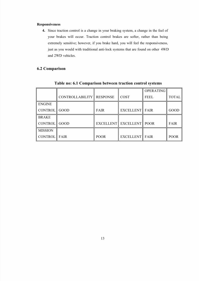
6.2 Comparison
Table no: 6.1 Comparison between traction control systems
CONTROLLABILITY
RESPONSE COST
OPERATING
FEEL TOTAL
ENGINE
CONTROL GOOD FAIR EXCELLENT FAIR GOOD
BRAKE
CONTROL GOOD EXCELLENT EXCELLENT POOR FAIR
MISSION
CONTROL FAIR POOR EXCELLENT FAIR POOR
8/8/2019 Ravi Main Pages7
http://slidepdf.com/reader/full/ravi-main-pages7 14/15

8/8/2019 Ravi Main Pages7
http://slidepdf.com/reader/full/ravi-main-pages7 15/15
15
CHAPTER: 8
CONCLUSION
From the above presentation it can be said that power can be saved by using a traction
control system in an automobile& slippage of an automobile can be avoided during fast
cornering very effectively. Out of the various types Traction control systems studied the
engine type traction control system was found to be most effective type of traction control
system. Due to some practical difficulties faced in the implementation of this kind of
system in automobiles. So brake type traction control system is preferred over the other
types of systems and this type of system is widely used in different automobiles.