Embed Size (px)
Citation preview

R&S®SMCV100BVector Signal GeneratorGetting Started
1432704602Version 03
(>PÔ^2)

This document describes the R&S®SMCV100B, stock no. 1432.7000.02 and itsoptions.
© 2021 Rohde & Schwarz GmbH & Co. KGMühldorfstr. 15, 81671 München, GermanyPhone: +49 89 41 29 - 0Email: [email protected]: www.rohde-schwarz.comSubject to change – data without tolerance limits is not binding.
R&S® is a registered trademark of Rohde & Schwarz GmbH & Co. KG.Trade names are trademarks of the owners.
1432.7046.02 | Version 03 | R&S®SMCV100B
The following abbreviations are used throughout this manual: R&S®SMCV100B is abbreviated asR&S SMCV100B, R&S®WinIQSIM2TM is abbreviated as R&S WinIQSIM2, R&S®VISA is abbreviated asR&S VISA.

ContentsR&S®SMCV100B
3Getting Started 1432.7046.02 ─ 03
Contents1 Safety and Regulatory Information...................................... 7
1.1 Safety Instructions................................................................................7
1.2 Labels on R&S SMCV100B.................................................................10
1.3 Korea Certification Class B................................................................10
2 Documentation Overview....................................................112.1 Getting Started Manual.......................................................................11
2.2 User Manuals and Help.......................................................................11
2.3 Service Manual....................................................................................12
2.4 Instrument Security Procedures....................................................... 12
2.5 Printed Safety Instructions................................................................ 12
2.6 Data Sheets and Brochures............................................................... 12
2.7 Release Notes and Open Source Acknowledgment (OSA).............13
2.8 Application Notes, Application Cards, White Papers, etc...............13
3 Key Features........................................................................ 14
4 Preparing for Use.................................................................154.1 Lifting and Carrying............................................................................15
4.2 Unpacking and Checking................................................................... 15
4.3 Choosing the Operating Site............................................................. 15
4.4 Setting Up the R&S SMCV100B......................................................... 16
4.4.1 Placing the R&S SMCV100B on a Bench Top...................................... 16
4.4.2 Mounting the R&S SMCV100B in a Rack............................................. 17
4.5 Important Aspects for Test Setup......................................................18
4.6 Connecting to Power.......................................................................... 19
4.7 Connecting to LAN............................................................................. 19

ContentsR&S®SMCV100B
4Getting Started 1432.7046.02 ─ 03
4.8 Connecting a Monitor......................................................................... 20
4.9 Connecting USB Devices................................................................... 21
4.10 Connecting to RF 50 Ω....................................................................... 22
4.11 Connecting to Ref In/Ref Out.............................................................23
4.12 Connecting to Dig. IQ HS x................................................................ 23
4.13 Connecting to IP Data Interface.........................................................25
4.14 Switching On or Off............................................................................ 26
5 Instrument Tour................................................................... 285.1 Front Panel Tour..................................................................................28
5.1.1 Touchscreen..........................................................................................29
5.1.2 Keys...................................................................................................... 30
5.1.2.1 On/Standby........................................................................................... 30
5.1.2.2 Utility Keys............................................................................................ 30
5.1.2.3 Function Keys....................................................................................... 30
5.1.2.4 Editing Keys.......................................................................................... 31
5.1.2.5 Navigation Controls...............................................................................31
Rotary Knob.......................................................................................... 31
5.1.3 Connectors............................................................................................32
5.2 Rear Panel Tour...................................................................................32
5.2.1 Connectors............................................................................................33
6 Trying Out the Instrument...................................................366.1 Generating an Unmodulated Carrier................................................. 37
6.2 Generating a Digitally Modulated Signal.......................................... 39
6.3 Triggering the Instrument with an External Signal.......................... 41
6.4 Enabling and Configuring a Marker Signal...................................... 47
6.5 Verifying the Generated Signal with the Graphics Display.............48
6.6 Saving and Recalling Settings...........................................................52

ContentsR&S®SMCV100B
5Getting Started 1432.7046.02 ─ 03
6.7 Generating a DAB Signal................................................................... 55
7 System Overview................................................................. 587.1 Brief Introduction to the Instrument's Concept............................... 58
7.2 Signal Flow at a Glance......................................................................58
7.3 Internal Baseband Source ("Baseband" Block)...............................60
7.4 Digital Baseband Input/Output ("BB Input"/ "I/Q Digital" Block)... 60
7.5 Additional White Gaussian Noise ("AWGN" Block).........................61
7.6 "I/Q Stream Mapper" Block................................................................ 61
7.7 I/Q Modulator ("I/Q Mod" Block)........................................................ 62
7.8 RF ("RF" Block)...................................................................................62
7.9 Applications Examples of the R&S SMCV100B............................... 62
8 Instrument Control.............................................................. 638.1 Possible Ways to Operate the Instrument........................................ 63
8.2 Means of Manual Interaction..............................................................64
8.3 Understanding the Display Information............................................64
8.3.1 Status Bar............................................................................................. 65
8.3.2 Block Diagram.......................................................................................66
8.3.3 Taskbar................................................................................................. 67
8.3.4 Additional Display Characteristics.........................................................68
8.4 Accessing the Functionality.............................................................. 70
8.5 Entering Data.......................................................................................71
8.5.1 Entering Numeric Parameters...............................................................72
8.5.2 Entering Alphanumeric Parameters...................................................... 73
8.5.3 Undo and Redo Actions........................................................................ 73
8.6 Getting Information and Help............................................................ 73
8.7 Remote Control................................................................................... 75

ContentsR&S®SMCV100B
6Getting Started 1432.7046.02 ─ 03
8.8 Remote Operation over VNC..............................................................76
9 Contacting Customer Support........................................... 77
Index..................................................................................... 78

Safety and Regulatory InformationR&S®SMCV100B
7Getting Started 1432.7046.02 ─ 03
1 Safety and Regulatory InformationThe product documentation helps you use the product safely and efficiently. Fol-low the instructions provided here and in the Chapter 1.1, "Safety Instructions",on page 7.
Intended use
The product is intended for the development, production and verification of elec-tronic components and devices in industrial, administrative, and laboratory envi-ronments. Use the product only for its designated purpose. Observe the operatingconditions and performance limits stated in the data sheet.
Where do I find safety information?
Safety information is part of the product documentation. It warns you of potentialdangers and gives instructions on how to prevent personal injury or damagecaused by dangerous situations. Safety information is provided as follows:● In Chapter 1.1, "Safety Instructions", on page 7. The same information is
provided in many languages as printed "Safety Instructions". The printed"Safety Instructions" are delivered with the product.
● Throughout the documentation, safety instructions are provided when youneed to take care during setup or operation.
1.1 Safety Instructions
Products from the Rohde & Schwarz group of companies are manufacturedaccording to the highest technical standards. To use the products safely, followthe instructions provided here and in the product documentation. Keep the prod-uct documentation nearby and offer it to other users.
Use the product only for its intended use and within its performance limits. Inten-ded use and limits are described in the product documentation such as the datasheet, manuals and the printed safety instructions. If you are unsure about theappropriate use, contact Rohde & Schwarz customer service.
Using the product requires specialists or specially trained personnel. These usersalso need sound knowledge of at least one of the languages in which the userinterfaces and the product documentation are available.
Safety Instructions

Safety and Regulatory InformationR&S®SMCV100B
8Getting Started 1432.7046.02 ─ 03
If any part of the product is damaged or broken, stop using the product. Neveropen the casing of the product. Only service personnel authorized byRohde & Schwarz are allowed to repair the product. Contact Rohde & Schwarzcustomer service at http://www.customersupport.rohde-schwarz.com.
Lifting and carrying the product
The maximum weight of the product is provided in the data sheet. To move theproduct safely, you can use lifting or transporting equipment such as lift trucksand forklifts. Follow the instructions provided by the equipment manufacturer.
Choosing the operating site
Only use the product indoors. The product casing is not waterproof. Water thatenters can electrically connect the casing with live parts, which can lead to elec-tric shock, serious personal injury or death if you touch the casing. IfRohde & Schwarz provides a carrying bag designed for your product, you canuse the product outdoors.
Unless otherwise specified, you can operate the product up to an altitude of2000 m above sea level. The product is suitable for pollution degree 2 environ-ments where nonconductive contamination can occur. For more information onenvironmental conditions such as ambient temperature and humidity, see thedata sheet.
Setting up the product
Always place the product on a stable, flat and level surface with the bottom of theproduct facing down. If the product is designed for different positions, secure theproduct so that it cannot fall over.
If the product has foldable feet, always fold the feet completely in or out to ensurestability. The feet can collapse if they are not folded out completely or if the prod-uct is moved without lifting it. The foldable feet are designed to carry the weight ofthe product, but not an extra load.
If stacking is possible, keep in mind that a stack of products can fall over andcause injury.
If you mount products in a rack, ensure that the rack has sufficient load capacityand stability. Observe the specifications of the rack manufacturer. Always installthe products from the bottom shelf to the top shelf so that the rack standssecurely. Secure the product so that it cannot fall off the rack.
Safety Instructions

Safety and Regulatory InformationR&S®SMCV100B
9Getting Started 1432.7046.02 ─ 03
Connecting to power
The product is an overvoltage category II product and has to be connected to afixed installation used to supply energy-consuming equipment such as householdappliances and similar loads. Be aware that electrically powered products haverisks, such as electric shock, fire, personal injury or even death.
Take the following measures for your safety:● Before switching on the product, ensure that the voltage and frequency indica-
ted on the product match the available power source. If the power adapterdoes not adjust automatically, set the correct value and check the rating of thefuse.
● If a product has an exchangeable fuse, its type and characteristics are indica-ted next to the fuse holder. Before changing the fuse, switch off the instrumentand disconnect it from the power source. How to change the fuse is describedin the product documentation.
● Only use the power cable delivered with the product. It complies with country-specific safety requirements. Only insert the plug into an outlet with protectiveconductor terminal.
● Only use intact cables and route them carefully so that they cannot be dam-aged. Check the power cables regularly to ensure that they are undamaged.Also ensure that nobody can trip over loose cables.
● If the product needs an external power supply, use the power supply that isdelivered with the product or that is recommended in the product documenta-tion or a power supply that conforms to the country-specific regulations.
● Only connect the product to a power source with a fuse protection of maxi-mum 20 A.
● Ensure that you can disconnect the product from the power source at anytime. Pull the power plug to disconnect the product. The power plug must beeasily accessible. If the product is integrated into a system that does not meetthese requirements, provide an easily accessible circuit breaker at the systemlevel.
Cleaning the product
Use a dry, lint-free cloth to clean the product. When cleaning, keep in mind thatthe casing is not waterproof. Do not use liquid cleaning agents.
Meaning of safety labels
Safety labels on the product warn against potential hazards.
Safety Instructions

Safety and Regulatory InformationR&S®SMCV100B
10Getting Started 1432.7046.02 ─ 03
Potential hazardRead the product documentation to avoid personal injury or product damage.
Electrical hazardIndicates live parts. Risk of electric shock, fire, personal injury or even death.
Hot surfaceDo not touch. Risk of skin burns. Risk of fire.
Protective conductor terminalConnect this terminal to a grounded external conductor or to protective ground. Thisprotects you against electric shock should an electric problem occur.
1.2 Labels on R&S SMCV100B
Labels on the casing inform about:● Personal safety, see "Connecting to power" on page 9.● Product and environment safety, see Table 1-1.● Identification of the product, see the serial number on the rear panel.
Table 1-1: Labels regarding R&S SMCV100B and environment safety
Labeling in line with EN 50419 for disposal of electrical and electronic equipment afterthe product has come to the end of its service life. For more information, see the prod-uct user manual, chapter "Disposal".
1.3 Korea Certification Class B
이 기기는 가정용(B급) 전자파 적합기기로서 주로 가정에서 사용하는 것을 목적으로 하며, 모든 지역에서 사용할 수 있습니다.
Korea Certification Class B
Documentation OverviewR&S®SMCV100B
11Getting Started 1432.7046.02 ─ 03
2 Documentation OverviewThis section provides an overview of the R&S SMCV100B user documentation.Unless specified otherwise, you find the documents on the R&S SMCV100Bproduct page at:
www.rohde-schwarz.com/manual/smcv100b
2.1 Getting Started Manual
Introduces the R&S SMCV100B and describes how to set up and start workingwith the product. Includes basic operations, typical measurement examples, andgeneral information, e.g. safety instructions, etc. A printed version is deliveredwith the instrument.
2.2 User Manuals and Help
Separate manuals for the base unit and the software options are provided fordownload:● Base unit manual
Contains the description of all instrument modes and functions. It also pro-vides an introduction to remote control, a complete description of the remotecontrol commands with programming examples, and information on mainte-nance, instrument interfaces and error messages. Includes the contents of thegetting started manual.
● Software option manualContains the description of the specific functions of an option. Basic informa-tion on operating the R&S SMCV100B is not included.
The contents of the user manuals are available as help in the R&S SMCV100B.The help offers quick, context-sensitive access to the complete information for thebase unit and the software options.
All user manuals are also available for download or for immediate display on theInternet.
User Manuals and Help

Documentation OverviewR&S®SMCV100B
12Getting Started 1432.7046.02 ─ 03
2.3 Service Manual
Describes the performance test for checking compliance with rated specifications,firmware update, troubleshooting, adjustments, installing options and mainte-nance.
The service manual is available for registered users on the globalRohde & Schwarz information system (GLORIS):
https://gloris.rohde-schwarz.com
2.4 Instrument Security Procedures
Deals with security issues when working with the R&S SMCV100B in secureareas. It is available for download on the Internet.
2.5 Printed Safety Instructions
Provides safety information in many languages. The printed document is deliv-ered with the product.
2.6 Data Sheets and Brochures
The data sheet contains the technical specifications of the R&S SMCV100B. Italso lists the options and their order numbers and optional accessories.
The brochure provides an overview of the instrument and deals with the specificcharacteristics.
See www.rohde-schwarz.com/brochure-datasheet/smcv100b
Data Sheets and Brochures

Documentation OverviewR&S®SMCV100B
13Getting Started 1432.7046.02 ─ 03
2.7 Release Notes and Open Source Acknowledg-ment (OSA)
The release notes list new features, improvements and known issues of the cur-rent firmware version, and describe the firmware installation.
The open-source acknowledgment document provides verbatim license texts ofthe used open source software.
See www.rohde-schwarz.com/firmware/smcv100b
2.8 Application Notes, Application Cards, WhitePapers, etc.
These documents deal with special applications or background information onparticular topics.
See www.rohde-schwarz.com/application/smcv100b
Application Notes, Application Cards, White Papers, etc.

Key FeaturesR&S®SMCV100B
14Getting Started 1432.7046.02 ─ 03
3 Key FeaturesThe R&S SMCV100B is a new signal generator in the economy range developedto meet demanding customer requirements. Offering excellent signal characteris-tic and straightforward and intuitive operation, the signal generator makes signalgeneration fast and easy.
Outstanding key features of the R&S SMCV100B are:
● First multi-standard platform for broadcast, navigation, cellular and wirelessapplications
● Fully software defined vector signal generator● Modern RF signal generation concept from 8 kHz to 7.125 GHz● High RF output power of up to 25 dBm● Modulation bandwidth up to 240 MHz with internal baseband● Powerful internal baseband generator with internal broadcast real-time coder,
Custom Digital Modulation and internal baseband signal generation with ARB● Support of terrestrial, satellite and audio broadcast standards such as ATSC
3.0, ATSC-M/H, DTMB, DVB-T2, DVB-T, ISDB-T, ISDB-TSB, T-DMB/DAB,DVB-S2, DVB-S, DRM/DRM+, Audio AM/FM, RDS/RDBS/DARC
● Support of digital standard waveforms such as 5G NR, LTE includingeMTC/NB-IoT, WLAN IEEE 802.11a/b/g/n/j/p/ac/ax
● Intuitive operation via 5'' touchscreen with block diagram as key element● Graphical signal monitoring at practically every point in the signal flow● SCPI macro recorder and code generator for generating executable remote
control code from manual operating steps (for MATLAB®, CVI, etc.)● Easily extendable with software options● Full remote compatibility with R&S SFE/R&S SFE100
For more information, see data sheet.

Preparing for UseR&S®SMCV100B
15Getting Started 1432.7046.02 ─ 03
4 Preparing for UseHere, you can find basic information about setting up the instrument for the firsttime.
4.1 Lifting and Carrying
See also "Lifting and carrying the product" on page 8.
For mounting the R&S SMCV100B in a rack, see Chapter 4.4.2, "Mounting theR&S SMCV100B in a Rack", on page 17.
4.2 Unpacking and Checking
1. Unpack the R&S SMCV100B carefully.
2. Retain the original packing material. Use it to protect the control elements andconnectors when transporting or shipping the R&S SMCV100B later.See also chapter "Transporting" in the user manual.
3. Using the delivery notes, check the equipment for completeness.
4. Check the equipment for damage.
If the delivery is incomplete or equipment is damaged, contactRohde & Schwarz.
4.3 Choosing the Operating Site
Specific operating conditions ensure proper operation and avoid damage to theproduct and connected devices. For information on environmental conditionssuch as ambient temperature and humidity, see the data sheet.
See also "Choosing the operating site" on page 8.
Choosing the Operating Site

Preparing for UseR&S®SMCV100B
16Getting Started 1432.7046.02 ─ 03
Electromagnetic compatibility classes
The electromagnetic compatibility (EMC) class indicates where you can operatethe product. The EMC class of the product is given in the data sheet under "Gen-eral data".● Class B equipment is suitable for use in:
– Residential environments– Environments that are directly connected to a low-voltage supply network
that supplies residential buildings● Class A equipment is intended for use in industrial environments. It can cause
radio disturbances in residential environments due to possible conducted andradiated disturbances. It is therefore not suitable for class B environments.If class A equipment causes radio disturbances, take appropriate measures toeliminate them.
4.4 Setting Up the R&S SMCV100B
See also:● "Setting up the product" on page 8.● "Intended use" on page 7.
4.4.1 Placing the R&S SMCV100B on a Bench Top
To place the product on a bench top
1. Place the product on a stable, flat and level surface. Ensure that the surfacecan support the weight of the product. For information on the weight, see thedata sheet.
2. CAUTION! Foldable feet can collapse. See "Setting up the product"on page 8.Always fold the feet completely in or out. With folded-out feet, do not placeanything on top or underneath the product.
3. WARNING! A stack of products can fall over and cause injury. Never stackmore than three products on top of each other. Instead, mount them in a rack.Stack as follows:
Setting Up the R&S SMCV100B

Preparing for UseR&S®SMCV100B
17Getting Started 1432.7046.02 ─ 03
● If the products have foldable feet, fold them in completely.● All products must have the same dimensions (width and length).● Do not exceed a total load of 50 kg placed on the product at the bottom of
the stack.
Left = Stacked correctlyMiddle left = Stacked incorrectly, too many productsMiddle right = Stacked incorrectly, different dimensionsRight = Stacked incorrectly, different dimensions, folded-out feet
4. NOTICE! Overheating can damage the product.Prevent overheating as follows:● Keep a minimum distance of 10 cm between the fan openings of the prod-
uct and any object in the vicinity.● Do not place the product next to heat-generating equipment such as radia-
tors or other products.
4.4.2 Mounting the R&S SMCV100B in a Rack
To prepare the rack
1. Observe the requirements and instructions in "Setting up the product"on page 8.
2. NOTICE! Insufficient airflow can cause overheating and damage the product.Design and implement an efficient ventilation concept for the rack.
To mount the R&S SMCV100B in a rack
1. Use an adapter kit that fits the dimensions of the R&S SMCV100B to preparethe instrument for rack mounting. For information on the dimensions, see datasheet.a) Order the rack adapter kit designed for the R&S SMCV100B. For the order
number, see data sheet.
Setting Up the R&S SMCV100B

Preparing for UseR&S®SMCV100B
18Getting Started 1432.7046.02 ─ 03
b) Mount the adapter kit. Follow the assembly instructions provided with theadapter kit.
2. Lift the R&S SMCV100B to shelf height.
3. Push the R&S SMCV100B onto the shelf until the rack brackets fit closely tothe rack.
4. Tighten all screws at the rack brackets with a tightening torque of 1.2 Nm tosecure the R&S SMCV100B at the rack.
To unmount the R&S SMCV100B from a rack
1. Loosen the screws at the rack brackets.
2. Bring the lifting equipment to shelf height.
3. Remove the R&S SMCV100B from the rack.
4. If placing the R&S SMCV100B on a bench top again, unmount the adapter kitfrom the R&S SMCV100B. Follow the instructions provided with the adapterkit.
4.5 Important Aspects for Test Setup
Cable selection and electromagnetic interference (EMI)
Electromagnetic interference (EMI) can affect the measurement results.
To suppress electromagnetic radiation during operation:● Use high-quality shielded cables, especially for the following connector types:
– BNCDouble-shielded BNC cables.
– USBDouble-shielded USB cables.How to: Chapter 4.9, "Connecting USB Devices", on page 21.See also chapter "Troubleshooting and Error Messages" in the user man-ual.
– LANAt least CAT6 STP cables.How to: Chapter 4.7, "Connecting to LAN", on page 19
Important Aspects for Test Setup

Preparing for UseR&S®SMCV100B
19Getting Started 1432.7046.02 ─ 03
● Always terminate open cable ends.● Ensure that connected external devices comply with EMC regulations.● Use the cable R&S DIGIQ-HS for connection to the "Dig. IQ HS x" interfaces
of the instrument. The cable is available under material number 3641.2948.03.How to: Chapter 4.12, "Connecting to Dig. IQ HS x", on page 23
● Use an SFP+ to RJ-45 adapter and an RJ-45 cable for connection to the "IPData" interface of the instrument. We recommend that you use the adapter"FCLF850P2BTL" from Finisar available under material number3627.0570.00.How to: Chapter 4.13, "Connecting to IP Data Interface", on page 25
Signal input and output levels
Information on signal levels is provided in the data sheet. Keep the signal levelswithin the specified ranges to avoid damage to the R&S SMCV100B and connec-ted devices.
4.6 Connecting to Power
For safety information, see "Connecting to power" on page 9.
1. Plug the AC power cable into the AC power connector on the rear panel of theinstrument. Only use the AC power cable delivered with the R&S SMCV100B.
2. Plug the AC power cable into a power outlet with ground contact.The required ratings are listed next to the AC power connector and in the datasheet.
4.7 Connecting to LAN
Network environment
Before connecting the product to a local area network (LAN), consider the follow-ing:● Install the latest firmware to reduce security risks.● For internet or remote access, use secured connections if applicable.
Connecting to LAN

Preparing for UseR&S®SMCV100B
20Getting Started 1432.7046.02 ─ 03
● Ensure that the network settings comply with the security policies of your com-pany. Contact your local system administrator or IT department before con-necting your product to your company LAN.
● When connected to the LAN, the product may potentially be accessed fromthe internet, which may be a security risk. For example, attackers might mis-use or damage the product.
To connect to LAN
The connector is located on the rear panel.
► Connect the LAN socket via an RJ-45 cable to the LAN.
By default, the R&S SMCV100B is configured to use DHCP (dynamic host config-uration protocol) and no static IP address is configured.
If switched on and connected to the LAN, the R&S SMCV100B displays theaddress information on the screen.
Figure 4-1: IP address indication on the screen (example)
See also the chapter "Connecting the Instrument to the Network (LAN)" in theuser manual.
4.8 Connecting a Monitor
This section describes how to connect a monitor for direct operation of theR&S SMCV100B. You can skip the following procedure, if you only operate theR&S SMCV100B remotely.
The connector is located on the rear panel.
► Connect the monitor to the "DVI-D" socket.You can connect the following types of monitor sockets:● DVI-D: Connect it to the "DVI-D" socket.
DVI-A: not supportedDVI-I: not supported
Connecting a Monitor

Preparing for UseR&S®SMCV100B
21Getting Started 1432.7046.02 ─ 03
● HDMI: You need an adapter. Use a passive DVI to HDMI adapter.● VGA: You need an active adapter, DVI to VGA or Display Port to VGA.
Passive adapters do not work.
If the monitor provides touch functionality, an additional connection can berequired, for example, a USB connection. Refer to the documentation of yourmonitor.
4.9 Connecting USB Devices
USB connectors are located on the front panel and rear panel. You can connector disconnect all USB devices from the R&S SMCV100B during operation.
To connect USB storage devices
USB storage devices, such as memory sticks, allow easy data transfer from/to theR&S SMCV100B. You can also use them for firmware updates.
► Connect the USB storage device to any of the USB connectors.
To connect USB devices with external power supply
1. NOTICE! Connected devices with external power supply can feed back cur-rent into the 5 V power supply of the USB interface and thus damage theR&S SMCV100B.Ensure that there is no connection between the positive pole of the powersupply and the +5 V power pin of the USB interface (VBUS).
2. Connect the USB storage device to any of the USB connectors.
To connect a keyboard
► Connect the keyboard to any of the USB connectors.
When connected, the R&S SMCV100B detects the keyboard automatically. Adetected keyboard has the default layout English – US.
To connect a mouse
► Connect the mouse to any of the USB connectors.
Connecting USB Devices

Preparing for UseR&S®SMCV100B
22Getting Started 1432.7046.02 ─ 03
When connected, the R&S SMCV100B detects the mouse automatically.
To connect power sensors
You can connect power sensors of the R&S NRP families to any of the USB con-nectors.
See chapter "Using Power Sensors" in the user manual.
4.10 Connecting to RF 50 Ω
The connector is located on the front panel.
To prepare for connecting to RF 50 Ω
1. NOTICE! Damaged or not clean connections can lead to RF insertion lossand mismatch, and even premature wear of the connectors.Before connecting to the port, inspect the RF connector visually to check thatit is clean, undamaged and mechanically compatible.See the application note 1MA99 for information on how to handle and main-tain the RF port, to minimize measurement deviations and ensure its longevity.
2. NOTICE! Risk of instrument damage. Excessive reverse power or DC voltageat the "RF 50 Ω" connector can damage the instrument.Make sure that the values do not exceed the reverse power and DC limits asgiven in the data sheet.
3. If the R&S SMCV100B is switched on, deactivate the RF output, before con-necting an RF cable to the "RF 50 Ω" connector.In the block diagram, select the block "RF" > "RF Level" > "RF ON > Off".
4. Use a high-quality RF cable that matches the RF connector type.See "Cable selection and electromagnetic interference (EMI)" on page 18.
To connect to non-screwable connectors (BNC)
► To connect the RF cable with the "RF 50 Ω" connector, proceed as follows:a) Carefully align the connector of the cable and the "RF 50 Ω" connector
along a common axis.
Connecting to RF 50 Ω

Preparing for UseR&S®SMCV100B
23Getting Started 1432.7046.02 ─ 03
b) Mate the connectors along the common axis until the male pin of the con-nector of the cable engages with the female socket of the "RF 50 Ω" con-nector.
The connector types listed in this table represent the common connectors provi-ded by Rohde & Schwarz. It is considered as general information and thereforecan contain connector types that do not apply to your instrument.
See "RF 50 Ω" on page 32.
To prevent RF output switch-off
► NOTICE! If you set a too high output level without a load connected to theinstrument, the reverse power can exceed a limit forcing the R&S SMCV100Bto switch off the RF output.Connect a load with sufficient return loss as given in the data sheet.
4.11 Connecting to Ref In/Ref Out
The connector is located on the rear panel.
To connect to Ref In/Ref Out (reference < 1 GHz)
For connection, the R&S SMCV100B provides BNC connectors.
► Follow the instructions in "To connect to non-screwable connectors (BNC)"on page 22.
4.12 Connecting to Dig. IQ HS x
The "Dig. IQ HS x" connector comprises a QSFP+ (Quad Small Form-factor Plug-gable) socket, that has two components: a QSFP+ cage and a QSFP+ connector.The QSFP+ cable is equipped with the QSFP+ plug.
Connecting to Dig. IQ HS x

Preparing for UseR&S®SMCV100B
24Getting Started 1432.7046.02 ─ 03
12
3
1 = QSFP+ plug2 = QSFP+ cage3 = QSFP+ connector
The connector is located on the rear panel.
To connect to Dig. IQ HS x interface
1. For connection, use the QSFP+ cable R&S DIGIQ-HS.See "Cable selection and electromagnetic interference (EMI)" on page 18.
2. Hold the QSFP+ plug of the cable by its panes.
3. Turn the QSFP+ cable, so that the release tab shows upwards.
4. Insert and push the QSFP+ plug into the QSFP+ cage.
To disconnect from Dig. IQ HS x interface
1. NOTICE! If you pull the cable, you can damage the cable and the "Dig. IQ HSx" connector.Pull the release tab.
2. Pull the QSFP+ plug out of the QSFP+ cage.
See also chapters "Digital Baseband Input Settings" and "I/Q Digital Output Set-tings" in the user manual.
Connecting to Dig. IQ HS x

Preparing for UseR&S®SMCV100B
25Getting Started 1432.7046.02 ─ 03
4.13 Connecting to IP Data Interface
The "IP Data" connector comprises an SFP+ (Small Form-factor Pluggable)socket, that has two components an SFP+ cage and an SFP+ connector.
1
2
1 = SFP+ cage2 = SFP+ connector
The connector is located on the rear panel.
To connect to IP Data interface
1. For connection, use an SFP+ to RJ-45 adapter and an RJ-45 cable.See "Cable selection and electromagnetic interference (EMI)" on page 18.
4
3
3a1
22
Figure 4-2: Connecting to the IP Data interface
1 = RJ-45 cable and plug2 = Axis of connection3 = SFP+ to RJ-45 adapter3a = Bracket for mounting and releasing the adapter4 = SFP+ socket of the "IP Data" connector
2. Connect the SFP+ to RJ-45 adapter to the SFP+ socket of the "IP Data" con-nector first (Figure 4-2).a) Turn the adapter, so that the release bracket joints show upwards.b) At the RJ-45 socket of the adapter, open the release bracket, so that the
bracket shows upward.
Connecting to IP Data Interface

Preparing for UseR&S®SMCV100B
26Getting Started 1432.7046.02 ─ 03
c) Insert and push the adapter into the cage of the SFP+ socket of the "IPData" connector.
d) To mount the adapter, push the release bracket down to close the bracket.The adapter is connected to the "IP Data" connector.
3. Plug the RJ-45 cable into the RJ-45 socket of the adapter.
To disconnect from IP Data interface
1. Unplug the RJ-45 cable.
2. Open the release bracket.
3. Carefully pull the SFP+ to RJ-45 adapter out of the SFP+ socket of the "IPData" interface.
Use the "IP Data" interface as input of external coding IP data for broadcast base-band signals.
See also chapter "Local IP Data Network Settings" in the corresponding broad-cast standard user manuals.
4.14 Switching On or Off
The following table provides an overview of power states, LEDs and power switchpositions.
Table 4-1: Overview of power states
State LED Position of power switch
Off gray [0]
Standby orange [I]
Ready green [I]
To switch on the R&S SMCV100B
The R&S SMCV100B is off but connected to power. See Chapter 4.6, "Connect-ing to Power", on page 19.
1. Set the switch on the power supply to position [I].The switch is located on the rear panel.The LED of the [On/Standby] key is orange.
Switching On or Off

Preparing for UseR&S®SMCV100B
27Getting Started 1432.7046.02 ─ 03
2. Wait until the oven-controlled oscillator (OCXO) warms up. For the warm-uptime, see data sheet.
3. Press the [On/Standby] key.Key and LED are located on the front panel.The LED changes to green. The R&S SMCV100B boots.
When starting for the first time, the R&S SMCV100B starts with the defaultsettings. When restarting the instrument, the settings depend on the instru-ment configuration before shut-down.See the chapter "Saving and Recalling Instrument Settings" in the user man-ual.
When the instrument is switched on, it automatically monitors main functions. Youcan query erroneous functions. In addition to automatic monitoring, you can per-form maintenance tasks.
See:● Chapter "Querying Error Messages" in the user manual.● Chapter "Performing Maintenance Tasks" in the user manual.
To shut down the product
The product is in the ready state.
► Press the [On/Standby] key.The operating system shuts down. The LED changes to orange.
In the standby state, the power switch circuits and the OCXO are active. To deac-tivate them, disconnect the instrument from the power supply.
To disconnect from power
The R&S SMCV100B is in the standby state.
1. NOTICE! Risk of data loss. If you disconnect the product from power when itis in the ready state, you can lose settings and data. Shut it down first.Set the toggle switch on the power supply to position [0].The LED of the [On/Standby] key is switched off.
2. Disconnect the R&S SMCV100B from the power source.
Switching On or Off

Instrument TourR&S®SMCV100B
28Getting Started 1432.7046.02 ─ 03
5 Instrument TourThe following topics help you get familiar with the instrument and perform the firststeps:● Front Panel Tour● Rear Panel Tour
This section explains the control elements and the connectors of theR&S SMCV100B with the aid of the front and rear views. For specifications of theinterfaces, refer to the data sheet.
The meanings of the labels on the R&S SMCV100B are described in Chapter 1.2,"Labels on R&S SMCV100B", on page 10.
5.1 Front Panel Tour
This section provides an overview of the control elements and connectors of thefront panel of the R&S SMCV100B. On the rear panel, you find all further connec-tors of the unit.
4 5
2
17
36
Figure 5-1: Front panel view
1 = [On/Standby], see Chapter 5.1.2.1, "On/Standby", on page 302 = "USB" connector, see "USB" on page 323 = Utility keys, see Chapter 5.1.2.2, "Utility Keys", on page 304 = Touchscreen, see Chapter 5.1.1, "Touchscreen", on page 29
Front Panel Tour

Instrument TourR&S®SMCV100B
29Getting Started 1432.7046.02 ─ 03
5 = Rotary knob, see "Rotary Knob" on page 316 = Function keys and editing keys, see Chapter 5.1.2.3, "Function Keys", on page 30 and
Chapter 5.1.2.4, "Editing Keys", on page 317 = "RF 50 Ω" output connector, see Chapter 5.1.3, "Connectors", on page 32
5.1.1 Touchscreen
The block diagram and the most important settings are displayed on the screenon the front panel. Also, the screen display provides status and setting informa-tion and allows you to quickly reconfigure the signal flow. The screen is touch-sensitive, offering an alternative means of user interaction for quick and easyhandling of the instrument.
2
3
1
Figure 5-2: Touchscreen elements
1 = Status bar (frequency and level display)2 = Block diagram3 = Taskbar/softkey bar
Any user interface elements that react to a click by a mouse pointer also react toa tap on the screen, and vice versa. Using the touchscreen, you can perform thefollowing tasks (among others) by the tap of your finger:● Changing a setting● Selecting new settings● Scrolling through a list or a table of parameters● Saving or recalling settings
Front Panel Tour

Instrument TourR&S®SMCV100B
30Getting Started 1432.7046.02 ─ 03
● Opening and closing dialogs
See also:● Chapter 8.2, "Means of Manual Interaction", on page 64, for operating the
touchscreen.● "Maintenance" in the user manual, for instructions on cleaning the screen.
5.1.2 Keys
5.1.2.1 On/Standby
The [On/Standby] key switches the instrument from the standby to the ready stateor vice versa.
The LED below the [On/Standby] key indicates the instrument state, see Chap-ter 4.14, "Switching On or Off", on page 26.
5.1.2.2 Utility Keys
The utility keys cause the R&S SMCV100B to return to a defined instrument stateand provide information on the instrument and assistance.
For more information, refer to chapter "General Instrument Functions" in the usermanual.
Table 5-1: Utility keys
Utility key Assigned functions
[Preset] Sets the instrument to a defined state
[Save/Rcl] Saves and loads instrument settingAccesses the file manager
[Help] Displays context-sensitive help text
5.1.2.3 Function Keys
Function keys provide access to most common generator settings and functions.
A detailed description of the corresponding functions is provided in the user man-ual.
Front Panel Tour
Instrument TourR&S®SMCV100B
31Getting Started 1432.7046.02 ─ 03
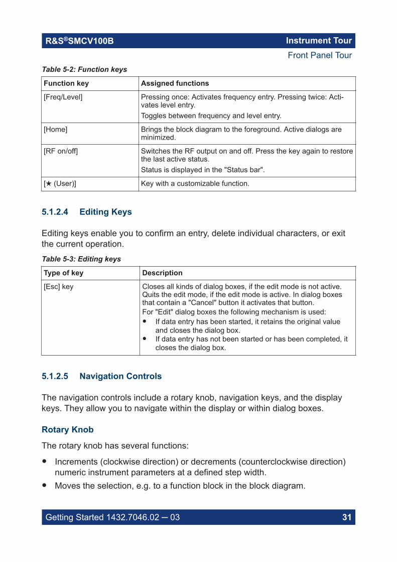
Table 5-2: Function keys
Function key Assigned functions
[Freq/Level] Pressing once: Activates frequency entry. Pressing twice: Acti-vates level entry.Toggles between frequency and level entry.
[Home] Brings the block diagram to the foreground. Active dialogs areminimized.
[RF on/off] Switches the RF output on and off. Press the key again to restorethe last active status.Status is displayed in the "Status bar".
[★ (User)] Key with a customizable function.
5.1.2.4 Editing Keys
Editing keys enable you to confirm an entry, delete individual characters, or exitthe current operation.
Table 5-3: Editing keys
Type of key Description
[Esc] key Closes all kinds of dialog boxes, if the edit mode is not active.Quits the edit mode, if the edit mode is active. In dialog boxesthat contain a "Cancel" button it activates that button.For "Edit" dialog boxes the following mechanism is used:● If data entry has been started, it retains the original value
and closes the dialog box.● If data entry has not been started or has been completed, it
closes the dialog box.
5.1.2.5 Navigation Controls
The navigation controls include a rotary knob, navigation keys, and the displaykeys. They allow you to navigate within the display or within dialog boxes.
Rotary Knob
The rotary knob has several functions:
● Increments (clockwise direction) or decrements (counterclockwise direction)numeric instrument parameters at a defined step width.
● Moves the selection, e.g. to a function block in the block diagram.
Front Panel Tour

Instrument TourR&S®SMCV100B
32Getting Started 1432.7046.02 ─ 03
● Shifts the selection bar within focused areas (e.g. lists).● Activates editing of entries or confirms and terminates entries.● Opens a context-sensitive menu, when it is pressed and held.
5.1.3 Connectors
The "RF 50 Ω" connector and "USB" connector are on the front panel.
USBThere is one female USB (universal serial bus) 2.0 connector of type A (hostUSB) on the front panel. You can connect, for example, a keyboard, a mouse or aUSB memory stick.Further "USB" connectors of type A are available on the rear panel.How to: Chapter 4.9, "Connecting USB Devices", on page 21.
RF 50 ΩOutput of the RF signal (N female connector).How to: Chapter 4.10, "Connecting to RF 50 Ω", on page 22
5.2 Rear Panel Tour
This section provides an overview of the connectors on the rear panel of theinstrument. For technical data of the connectors, refer to the data sheet.
Rear Panel Tour

Instrument TourR&S®SMCV100B
33Getting Started 1432.7046.02 ─ 03
51 2 43
6789
Figure 5-3: Rear panel
1 = AC power supply connection and main power switch, see "AC power supply connector andswitch" on page 33
2 = "DVI-D" connector (output), see "DVI-D" on page 333 = Serial number (six digits in the string 1432.7000.02-<serial number>-<checksum>)4 = "LAN" connector, see "LAN" on page 345 = "USB" connectors, see "USB" on page 346 = "Dig. IQ HS x" connector, see "Dig. IQ HS x" on page 347 = "IP Data" connector, see "IP Data" on page 348 = "User x" connectors, "User x" on page 349 = "Ref In"/"Ref Out" connectors, see "Ref In/Ref Out" on page 35
5.2.1 Connectors
AC power supply connector and switchMains power switch for performing the following tasks:● Connecting the internal power supply to the power source● Disconnecting the internal power supply from the power sourceHow to: Chapter 4.6, "Connecting to Power", on page 19.
DVI-DDVI-D socket. Output for the monitor signal of the built-in computer. The connec-ted computer monitor should provide a resolution of 1024x768 pixels or higher.How to: Chapter 4.8, "Connecting a Monitor", on page 20
Rear Panel Tour

Instrument TourR&S®SMCV100B
34Getting Started 1432.7046.02 ─ 03
LANRJ-45 connector to connect the R&S SMCV100B to a LAN for remote control,remote operation, and data transfer.How to: Chapter 4.7, "Connecting to LAN", on page 19
USBThere are two female USB (universal serial bus) 3.0 connectors of type A (hostUSB) on the rear panel. They have the same functionality as the USB connectorson the front panel, but provide higher data rates. See "USB" on page 32.How to: Chapter 4.9, "Connecting USB Devices", on page 21.
Dig. IQ HS xConnectors for the input/output of high-speed digital I/Q signals, for example,from and to Rohde & Schwarz instruments.Table 5-4 lists the interface designation (input/output) and the required option.For more information, see data sheet.Table 5-4: Overview of Dig. IQ HS x interfaces and required options
Interface Designation Required option
"Dig. IQ HS 1" "BB Input" R&S SMCVB-K19 digital baseband interface
"Dig. IQ HS 2" "I/Q Digital Out"
The interface is a QSFP+ (Quad Small Form-factor Pluggable) module. It sup-ports max. bandwidth of up to 50 Gsample/s with optical active cables.How to: Chapter 4.12, "Connecting to Dig. IQ HS x", on page 23
IP DataInterface for input of IP data for real-time encoding in broadcast baseband sig-nals.The interface comprises a SFP+ (Small Form-factor Pluggable) socket.How to: Chapter 4.13, "Connecting to IP Data Interface", on page 25
User xBNC multipurpose connectors for defining input signals and output signals.Table 5-5 lists the signals assigned to the "User x" connectors in the defaultinstrument state.
Rear Panel Tour

Instrument TourR&S®SMCV100B
35Getting Started 1432.7046.02 ─ 03
Table 5-5: Default configuration of the User x connectors
"User" connector Direction Default assigned signal
1 Output Baseband Marker 1
2 Input Global Clock
A dedicated LED indicates the connector status:● green: an input connector● yellow: an output connector● red: error● no light / gray: the connector is not active● blinking LED: connection indication as result of the "Identify Connector"
functionSee also chapter "Global Connector Settings" in the user manual.
Ref In/Ref OutInput/output for external reference signal.BNC connectors for reference signals from 1 MHz to 100 MHz.How to: Chapter 4.11, "Connecting to Ref In/Ref Out", on page 23
Rear Panel Tour

Trying Out the InstrumentR&S®SMCV100B
36Getting Started 1432.7046.02 ─ 03
6 Trying Out the InstrumentThis chapter introduces the most important functions and settings of theR&S SMCV100B step by step.
The complete description of the functionality and its usage is given in theR&S SMCV100B user manual. Basic instrument operation is described in Chap-ter 8, "Instrument Control", on page 63.
Prerequisites
● R&S SMCV100B equipped with its minimum configuration:– Base unit– Frequency option R&S SMCVB-B103
● The R&S SMCV100B is connected to the power supply, and started up asdescribed in Chapter 4, "Preparing for Use", on page 15.
For the first signal generation tasks, you use the internal baseband and referencesignal, so you do not need any additional signal source. More complex signalgeneration tasks, however, require an instrument equipped with additional optionsand/or external signals. Each task description lists its prerequisites.
The screenshots in this description show a fully equipped instrument. Con-sider that, the block diagram displayed on your particular instrument can dif-fer from the one used in the example.
Touchscreen operation
For detailed information on touchscreen operation, see Chapter 8.2, "Means ofManual Interaction", on page 64.
The following sections provide introductory operation examples using the touch-screen.
● Generating an Unmodulated Carrier............................................................... 37● Generating a Digitally Modulated Signal......................................................... 39● Triggering the Instrument with an External Signal...........................................41● Enabling and Configuring a Marker Signal......................................................47● Verifying the Generated Signal with the Graphics Display..............................48● Saving and Recalling Settings........................................................................ 52● Generating a DAB Signal................................................................................ 55

Trying Out the InstrumentR&S®SMCV100B
37Getting Started 1432.7046.02 ─ 03
6.1 Generating an Unmodulated Carrier
We start out by generating a simple unmodulated signal. The R&S SMCV100Bhas a minimum configuration as in "Prerequisites" on page 36.
1. On the R&S SMCV100B front panel, press the Preset key to start out in adefined instrument configuration.
2. Set the frequency:a) On the "Status Bar", tap the "Frequency" field.b) On the on-screen keypad, enter 1.955 and press the "GHz" key.
The on-screen keypad closes and the frequency value is displayed.
3. On the "Status Bar", tap the "Level" field and enter the level in the same way.
4. Select "Block Diagram > RF Block > On" to enable the output of the generatedunmodulated signal.
Generating an Unmodulated Carrier

Trying Out the InstrumentR&S®SMCV100B
38Getting Started 1432.7046.02 ─ 03
Figure 6-1: Block diagram: Generating an unmodulated signal
The 1.955 GHz signal is output at the "RF 50 Ω" connector at the front panelof the R&S SMCV100B.
Connect "RF 50 Ω" of the R&S SMCV100B to a signal analyzer, for exampleR&S®FSW, to display the generated signal.
Figure 6-2: Simplified test setup
For the required settings of the signal analyzer, refer to its user manual or itsonline help.
Generating an Unmodulated Carrier

Trying Out the InstrumentR&S®SMCV100B
39Getting Started 1432.7046.02 ─ 03
6.2 Generating a Digitally Modulated Signal
This example shows you how to generate a simple WCDMA-3GPP (QPSK 45°offset) signal with the help of the "Custom Digital Modulation" functionality.
Prerequisites
● Minimum configuration as in "Prerequisites" on page 36● Option custom digital modulation R&S SMCVB-K199
The initial situation is not the instrument's preset state but rather the configurationdescribed in Chapter 6.1, "Generating an Unmodulated Carrier", on page 37.
1. In the block diagram, select "Baseband" and navigate to the section "Misc >Custom Digital Mod...".
The "Custom Digital Modulation" dialog opens.
2. In the "Custom Digital Modulation" dialog, select "General > Set according toStandard > WCDMA-3GPP".
3. Select "General > State > On" to enable signal generation.
Generating a Digitally Modulated Signal

Trying Out the InstrumentR&S®SMCV100B
40Getting Started 1432.7046.02 ─ 03
The instrument activates automatically "I/Q Mod", uses the internal trigger andclock signals, and generates a WCDMA-3GPP signal, modulated with aQPSK 45° offset modulation.
Figure 6-3: Block diagram: Generating a digitally modulated signal
Generating a Digitally Modulated Signal

Trying Out the InstrumentR&S®SMCV100B
41Getting Started 1432.7046.02 ─ 03
4. Optionally, select the "Modulation" tab and observe the used "ModulationType".
Figure 6-4: Display of the used modulation type
6.3 Triggering the Instrument with an External Sig-nal
The following configurations are rather theoretical cases, because you rarely usethe R&S SMCV100B as a standalone instrument. Usually, the instrument wouldbe connected to a device under test (DUT) and/or other measurement equipment.
Prerequisites
● Minimum configuration as in "Prerequisites" on page 36● Option custom digital modulation R&S SMCVB-K199
As a rule, whenever a test setup requires two or more devices, provide them witha common reference frequency. Some test setups require control of the signalgeneration start and an exact generation start time, determined by a defined trig-ger event. For example, by triggering the instrument internally or externally fromthe DUT.
The example below illustrates the general principle of external triggering andextends the configuration performed in Chapter 6.2, "Generating a Digitally Modu-lated Signal", on page 39 by the configuration of the required trigger signal andconnector settings.
This test setup requires one signal analyzer, like the R&S®FSW, as additionalequipment.
Triggering the Instrument with an External Signal

Trying Out the InstrumentR&S®SMCV100B
42Getting Started 1432.7046.02 ─ 03
To start signal generation synchronous to an external global trigger signal
The configuration requires three main steps with the following goals:
1. Observe the current connector configuration. Define an input connector for theexternal global trigger signal.See "To verify the current connector configuration" on page 42
2. Configure the baseband to use the external global trigger signal as triggersource.See "To reconfigure the trigger settings" on page 44
3. Connect the instrument and the external trigger source.See "To connect the instrument and the external trigger source" on page 45
To verify the current connector configuration
The R&S SMCV100B is equipped with multipurpose bi-directional "User" connec-tors. Because the signal direction, input or output, and the signal mapping areconfigurable, we recommend that you check the current configuration beforecabling or further instrument's configurations.
1. To display an overview of the current mapping of the logical signals to the con-nectors, perform one of the following:● In the block diagram, select the Trigger/Marker/Clock status LEDs on the
left side of the "Baseband" block.
● Select "Baseband > Trigger Marker Clock".
Triggering the Instrument with an External Signal

Trying Out the InstrumentR&S®SMCV100B
43Getting Started 1432.7046.02 ─ 03
The instrument uses its internal trigger and clock signals, and the default map-ping of the marker signals to the "User" connectors.
2. To access the related connector settings, perform one of the following:● Select "Global Connector Settings"● Tap the connector name, for example select the connector "User 1"
Figure 6-5: Signal mapping to the global connectors
The "Global Connectors" dialog displays the current connectors configuration.The settings are configurable, but in this example we use the default mapping.
3. Alternatively, select "Block Diagram > Baseband > Misc > Custom DigitalMod", select the "Trigger In" tab and select "Global Connector Settings".
In the current mapping, the two global connectors User x on the rear panel areconfigured as follows:● "Baseband Marker" signal is output at the "User 1" connector.
The LED next to the connector is orange.
Triggering the Instrument with an External Signal

Trying Out the InstrumentR&S®SMCV100B
44Getting Started 1432.7046.02 ─ 03
● The "User 2" connector is an input for the "Global Trigger" signal.The LED next to the connector is green.
Find the physical location of each connectorUse the built-in "Trigger Marker Clock > Show " function to display the loca-tion of the selected connector. A blinking marker on the front/rear panel viewalso indicates the selected connector.
To reconfigure the trigger settings
We assume that the instrument is configured as described in Chapter 6.2, "Gen-erating a Digitally Modulated Signal", on page 39 and the default connector map-ping is maintained (see Figure 6-5).
1. In the block diagram, select "Baseband > Misc > Custom Digital Mod > TriggerIn".
2. Select the following settings:a) "Mode > Armed Auto"b) "Source > External Global Trigger".
3. Select "Global Connector Settings > Routing".
4. For "User 2", select "Direction > Input" and "Signal > Global Trigger".
Triggering the Instrument with an External Signal

Trying Out the InstrumentR&S®SMCV100B
45Getting Started 1432.7046.02 ─ 03
The instrument expects an external global trigger event. In the current config-uration, the "Global Trigger" signal has to be supplied at the input connector"User" 2.The Trigger/Marker/Clock status LEDs in the block diagram confirm that anexternal trigger signal is selected; the signal generation is however stopped.
To connect the instrument and the external trigger source
1. Use a suitable cable to connect the external trigger source to the "User" 2connector of the R&S SMCV100B. See Figure 6-6.
Triggering the Instrument with an External Signal

Trying Out the InstrumentR&S®SMCV100B
46Getting Started 1432.7046.02 ─ 03
Figure 6-6: Simplified representation of a test setup**
** = The figure depicts the cabling as a general principle; particular test setups do not requireall connections at the same time
The Figure 6-6 depicts the location of the connectors and explains the con-nection as principle. In practice, you would rather "substitute" the analyzer bya DUT, like a base station (BS).Other than in the example, the DUT can be the source for the reference sig-nal. Instead of using an external trigger source, the DUT can also send, forexample, a frame trigger signal to the R&S SMCV100B. The R&S SMCV100Bacts still as the signal source.
2. Use suitable cables to connect to RF 50 Ω and Ref. In connectors of theR&S SMCV100B to the signal analyzer or the DUT.The R&S®FSW supplies the 10 MHz external reference signal.
Upon the receiving of an external trigger event, the R&S SMCV100B startsthe signal generation and then generates a continuous signal. An "Arm" stopsthe signal generation. A subsequent trigger event causes a restart of the sig-nal generation.
To learn more about this topic, refer to:● Chapter "Baseband Trigger Signals" in the user manual● Chapter "Global Connectors" in the user manual
Triggering the Instrument with an External Signal

Trying Out the InstrumentR&S®SMCV100B
47Getting Started 1432.7046.02 ─ 03
6.4 Enabling and Configuring a Marker Signal
Test setups often require synchronization of an external device with the generateddata stream. For this purpose, the R&S SMCV100B can output maximum twomarker signals (or markers) also to the generated signal.
The R&S SMCV100B provides four regular marker signals. You can output two ofthe marker signals, one to each of the "User"1/2 connectors.
With suitable marker settings for instance, you can mark slot or frame boundariesor mark the start of a particular modulation symbol.
Prerequisites
● Minimum configuration as in "Prerequisites" on page 36● Option custom digital modulation R&S SMCVB-K199
This example extends further the configurations performed in Chapter 6.2, "Gen-erating a Digitally Modulated Signal", on page 39. We assume a default connectormapping (see Figure 6-5).
This test setup requires one oscilloscope, like the R&S®RTO, as additional equip-ment.
1. In the block diagram, select "Block Diagram > Baseband > Misc > CustomDigital Mod > Marker" tab.
2. Select "Marker Mode > Marker 1 > Pulse" and "Divider = 32".Generated is a periodic marker with marker frequency of 120 KHz. The signalis output at the "User" 1 connector of the R&S SMCV100B (see Figure 6-5).
3. Use a suitable cable to connect the "User" 1 connector of theR&S SMCV100B to the monitoring instrument, for example an oscilloscopelike R&S®RTO. See Figure 6-7.
Enabling and Configuring a Marker Signal

Trying Out the InstrumentR&S®SMCV100B
48Getting Started 1432.7046.02 ─ 03
Figure 6-7: Simplified representation of a test setup for signal monitoring**
** = The figure depicts the cabling as a general principle
4. Use a suitable cable to connect the "RF 50 Ω" on page 32 connector of theR&S SMCV100B to the monitoring instrument.
To learn more about this topic, refer to chapter "Regular Marker Output Sig-nals" in the user manual.
6.5 Verifying the Generated Signal with the Graph-ics Display
It is often useful to check the spectra of the configured signals, before you enablethe RF output of the instrument. The R&S SMCV100B has a minimum configura-tion as in "Prerequisites" on page 36
The R&S SMCV100B provides a build-in function to represent the generated sig-nal on a graphical signal display. We demonstrate this feature by showing thecharacteristics at one particular point of the signal processing chain. You can,however, display the signal characteristics at other different stages.
This example shows you how to use this graphical display to verify the generatedsignal. Use the signal generated in Chapter 6.4, "Enabling and Configuring aMarker Signal", on page 47.
Verifying the Generated Signal with the Graphics Display

Trying Out the InstrumentR&S®SMCV100B
49Getting Started 1432.7046.02 ─ 03
To access the graphical signal display functionality
► Perform one of the following:● Select "Taskbar > System Configuration > Graphics".
● On the "Taskbar", tap the wave icon.
The "Graphics Configuration" dialog opens.
To visualize the signal
1. In the "Graphics Configuration" dialog, select "Mode > Constellation".
2. Select "Source > Baseband".
3. Select "Add" to enable signal display.
Verifying the Generated Signal with the Graphics Display

Trying Out the InstrumentR&S®SMCV100B
50Getting Started 1432.7046.02 ─ 03
In the "Summary" tab, you can verify, that "Channel 0" graphic is visible in thetable:
A new thumbnail (minimized view) indicating the active diagram appears inthe "Taskbar".
4. Press the thumbnail graphic.The graphic enlarges and the diagram is displayed in a normal size.
Verifying the Generated Signal with the Graphics Display

Trying Out the InstrumentR&S®SMCV100B
51Getting Started 1432.7046.02 ─ 03
The "Constellation Diagram" displays the 3GPP FDD signal.
5. To retrieve more information, zoom in. In some diagrams you can select"Show Marker" to measure the distance, for example, between two signals.In principle, the zoom in function works like the two-finger pinching for magni-fying images on your cellphone.
6. In the "Constellation Diagram" dialog, select "Configure" to return to the"Graphics Configuration" dialog.Close the "Graphics Configuration" dialog.This action has no effect on the configured graphics but on the dialog itself.
The block diagram displays the current signal routing. It indicates that fre-quency and power offsets are enabled and displays the acquisition points forthe real-time diagrams minimized in the "Taskbar".
Verifying the Generated Signal with the Graphics Display

Trying Out the InstrumentR&S®SMCV100B
52Getting Started 1432.7046.02 ─ 03
6.6 Saving and Recalling Settings
To restore the results of our measurements later, we save the instrument settingsto a file.
To save the instrument settings to a file
We assume, a test configuration as described in Chapter 6.4, "Enabling and Con-figuring a Marker Signal", on page 47.
1. Press the [Save/Rcl] key on the front panel.
2. In the "Save/Recall" dialog box, select "Operation Mode > Save".Tap the "Filename", use the on-screen keyboard, and enter MyTestSignal.
Saving and Recalling Settings

Trying Out the InstrumentR&S®SMCV100B
53Getting Started 1432.7046.02 ─ 03
3. Tap the "Save" button.
The file MyTestSignal.savrcltxt is saved in the default directory /var/user.
To load saved instrument settings
You can restore the settings to the instrument at any time using the settings file.
1. Press the Preset button to restore the default instrument settings.
2. Press the Save/Rcl key.
3. In the "Save/Recall" dialog, select "Recall" operation.Navigate to the directory of the saved file. Select the MyTestSignal file.
Saving and Recalling Settings

Trying Out the InstrumentR&S®SMCV100B
54Getting Started 1432.7046.02 ─ 03
4. Tap the "Recall" button.
All instrument settings are restored and the display resembles the instrumentdisplay right before the settings were saved.
To display all parameters with values different to their preset values
After loading saved instrument setting, visualize all parameters that have beenchanged from their default state.
1. In the block diagram, open the context-sensitive menu:a) Imitate a right-click.b) Tap and hold on an empty space in the block diagram for about one sec-
ond.
2. In the context-sensitive menu, select "Mark All Parameters Changed from Pre-set".
All changed parameters are highlighted.
Saving and Recalling Settings

Trying Out the InstrumentR&S®SMCV100B
55Getting Started 1432.7046.02 ─ 03
See also chapter "File and Data Management" in the user manual.
6.7 Generating a DAB Signal
The main application field of the R&S SMCV100B is the generation of digital sig-nals in accordance with broadcast standards, like DAB, DVB-T2 or ATSC3.0, toname a few. This example uses the digital broadcast standard DAB.
You can access and interact with the instrument and experience the advantagesprovided by the additional options.
Prerequisites
● Minimum configuration as in "Prerequisites" on page 36● Option "Enable broadcast standard" R&S SMCVB-K519● Option DAB/T-DMB R&S SMCVB-K156
To generate a DAB test signal
1. On the R&S SMCV100B front panel, press the Preset key to start out in adefined instrument configuration.
Generating a DAB Signal
Trying Out the InstrumentR&S®SMCV100B
56Getting Started 1432.7046.02 ─ 03
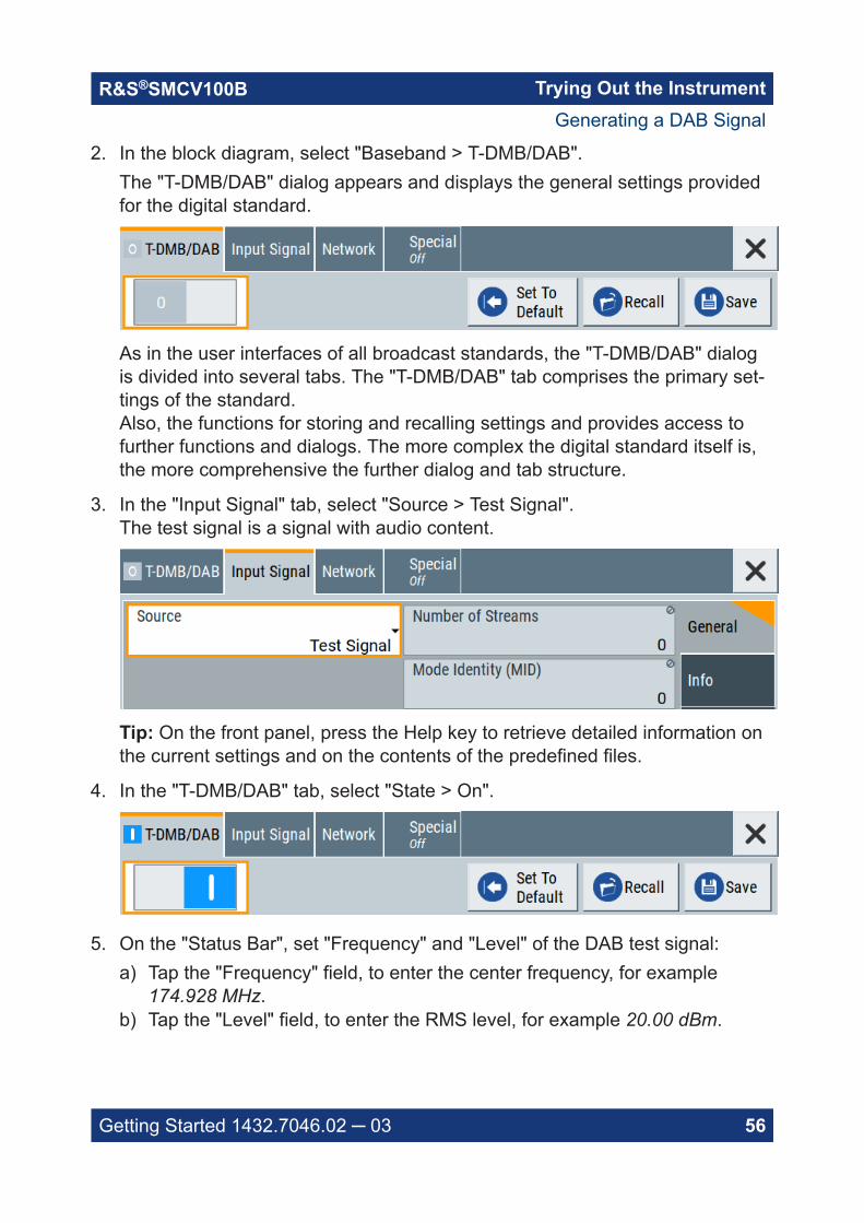
2. In the block diagram, select "Baseband > T-DMB/DAB".The "T-DMB/DAB" dialog appears and displays the general settings providedfor the digital standard.
As in the user interfaces of all broadcast standards, the "T-DMB/DAB" dialogis divided into several tabs. The "T-DMB/DAB" tab comprises the primary set-tings of the standard.Also, the functions for storing and recalling settings and provides access tofurther functions and dialogs. The more complex the digital standard itself is,the more comprehensive the further dialog and tab structure.
3. In the "Input Signal" tab, select "Source > Test Signal".The test signal is a signal with audio content.
Tip: On the front panel, press the Help key to retrieve detailed information onthe current settings and on the contents of the predefined files.
4. In the "T-DMB/DAB" tab, select "State > On".
5. On the "Status Bar", set "Frequency" and "Level" of the DAB test signal:a) Tap the "Frequency" field, to enter the center frequency, for example
174.928 MHz.b) Tap the "Level" field, to enter the RMS level, for example 20.00 dBm.
Generating a DAB Signal
Trying Out the InstrumentR&S®SMCV100B
57Getting Started 1432.7046.02 ─ 03
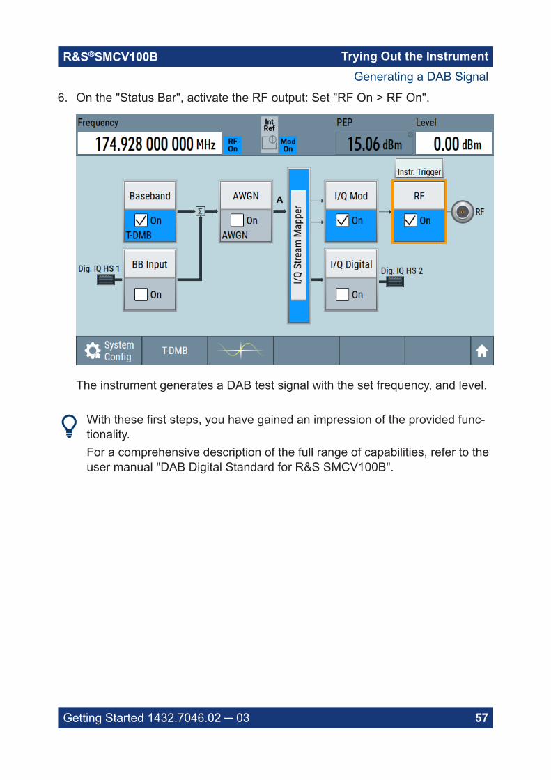
6. On the "Status Bar", activate the RF output: Set "RF On > RF On".
The instrument generates a DAB test signal with the set frequency, and level.
With these first steps, you have gained an impression of the provided func-tionality.For a comprehensive description of the full range of capabilities, refer to theuser manual "DAB Digital Standard for R&S SMCV100B".
Generating a DAB Signal
System OverviewR&S®SMCV100B
58Getting Started 1432.7046.02 ─ 03
7 System OverviewThis section helps you to get familiar with the R&S SMCV100B. It provides anintroduction to the general concept of the instrument. This section also introducesthe main blocks in the signal generation flow.
For information on how to access functions and interact with theR&S SMCV100B, refer to Chapter 8, "Instrument Control", on page 63.
7.1 Brief Introduction to the Instrument's Concept
The R&S SMCV100B offers excellent RF and baseband characteristics. Thebaseband section of the R&S SMCV100B is fully digital. It contains the hardwarefor generating and processing I/Q signals in realtime or generating signals with anarbitrary waveform generator.
7.2 Signal Flow at a Glance
The R&S SMCV100B is equipped with a large touchscreen, that displays a blockdiagram. The block diagram represents the signal flow and the general stages thesignal generation goes through. Depending on the options the R&S SMCV100B isequipped with, the appearance of the block diagram changes.
The following examples do not cover all possible cases but aim to introduce theway the block diagram depicts the installed options.● Minimum configuration example of a base unit and frequency option
R&S SMCVB-B103.
Signal Flow at a Glance

System OverviewR&S®SMCV100B
59Getting Started 1432.7046.02 ─ 03
● An example of a fully equipped instrument.The block diagram displays all blocks for that the required hardware and soft-ware options are fitted. The block diagram shows the signal flow as it is.
The cross-reference between the installed options and the displayed set-tings
The Table 7-1 is an excerpt of the available options and lists only the optionsrequired to display a functional block in the block diagram. The informationassumes R&S SMCV100B minimum configuration comprising base unit and fre-quency option R&S SMCVB-B103.
For exact information on the available options, and on the minimum requirementsand the interdependencies between the provided options, refer to theR&S SMCV100B data sheet.
Signal Flow at a Glance

System OverviewR&S®SMCV100B
60Getting Started 1432.7046.02 ─ 03
Table 7-1: Required options per functional block (excerpt)
Functional block Required option
"Baseband" -
"BB Input" R&S SMCVB-K19
"AWGN" R&S SMCVB-K62
"I/Q Stream Mapper" -
"I/Q Mod" -
"I/Q Digital" R&S SMCVB-K19
"RF" -
7.3 Internal Baseband Source ("Baseband" Block)
The "Baseband" block represents the source of the baseband signals (base-bands).
This functional block is the access point to:● The internal baseband generator
The baseband generator contains modules for real-time signal generation("Custom Digital Modulation" requires R&S SMCVB-K199) and an arbitrarywaveform generator (ARB).
● The available digital standardsGeneration of digital signals in accordance with the supported standardsrequires additional software options. For example, option R&S SMCVB-K162generates signals according to the ATSC 3.0 standard.
● The baseband offsets functionSignals from the baseband generator can be shifted in frequency and phase.
7.4 Digital Baseband Input/Output ("BB Input"/ "I/QDigital" Block)
The "BB Input" and the "I/Q Digital" blocks are the access point to the settings ofthe digital interfaces "Dig. IQ HS x".
Digital Baseband Input/Output ("BB Input"/ "I/Q Digital" Block)

System OverviewR&S®SMCV100B
61Getting Started 1432.7046.02 ─ 03
Equipped with option R&S SMCVB-K19, the R&S SMCV100B is able to receivedigital baseband signals and to output digital baseband signals. You can use bothinterfaces in parallel: "Dig. IQ HS 1" is input and "Dig. IQ HS 2" is output of thedigital baseband signals.
The digital baseband inputs and outputs can be used together with otherRohde & Schwarz instruments, like signal generators. A Rohde & Schwarz signalgenerator for instance can serve as digital signal source in test configurationrequiring two baseband sources.
The "BB Input" block is the access point to the settings of:● The external digital I/Q signals
The external digital I/Q signals are further processed in the baseband section.● The baseband offsets function
The external and internal baseband signals can be shifted in frequency andphase.
The "I/Q Digital" block is the access point to the settings of the digital I/Q outputsignals.
7.5 Additional White Gaussian Noise ("AWGN"Block)
The "AWGN" block is displayed only in instruments equipped with the optionR&S SMCVB-K62. This block controls the additional white Gaussian noise gener-ator (AWGN). An additive white noise is required for measurements of mobileradio base stations.
7.6 "I/Q Stream Mapper" Block
As one of the access points to the system configuration settings, the "I/Q StreamMapper" provides direct access for mapping the generated I/Q streams to theavailable output connectors. That is, to the analog "RF 50 Ω" output connectorand to the digital "Dig. IQ HS 2" output connectors.
"I/Q Stream Mapper" Block

System OverviewR&S®SMCV100B
62Getting Started 1432.7046.02 ─ 03
7.7 I/Q Modulator ("I/Q Mod" Block)
The "I/Q Mod" block represents the I/Q modulator.
This functional block is the access point to:● The I/Q modulation of the internal baseband signal● The digital I/Q impairments
7.8 RF ("RF" Block)
The "RF" block represents the RF settings of the instrument.
This block is the access point to:● RF frequency and level settings, and the reference frequency, user correction,
etc.● The list and sweep modes
7.9 Applications Examples of the R&S SMCV100B
The R&S SMCV100B can be optimally adapted to the requirements of differentapplications:
● Generation of digitally modulated signals using– The internal baseband generator– The externally applied digital baseband signals
● Generation of wanted signals or interfering signals for receiver tests● Generation of signals with up to 240 MHz signal bandwidth
Applications Examples of the R&S SMCV100B

Instrument ControlR&S®SMCV100B
63Getting Started 1432.7046.02 ─ 03
8 Instrument ControlThis chapter provides an overview on how to work with the R&S SMCV100B.
It covers the following topics:
● Possible Ways to Operate the Instrument.......................................................63● Means of Manual Interaction...........................................................................64● Understanding the Display Information........................................................... 64● Accessing the Functionality.............................................................................70● Entering Data.................................................................................................. 71● Getting Information and Help.......................................................................... 73● Remote Control............................................................................................... 75● Remote Operation over VNC.......................................................................... 76
8.1 Possible Ways to Operate the Instrument
There are three ways to operate the R&S SMCV100B:● Manual operation:
Use the touchscreen, hard keys and rotary knob, or an optional mouse and/orkeyboard.The following description shows how to operate the instrument manually.
● Remote control:Create programs to automatize repeating settings, tests and measurements.The instrument is connected to a computer running the program.This way of operation is described in the user manual, chapter "Network andRemote Control Operation".
● Remote operation from a computer:Remote monitoring and control of the instrument from a connected computeris based on the common cross-platform technology VNC (Virtual NetworkComputing). On the remote computer, any standard web browser (supportingJava) or a dedicated VNC client (like Ultr@VNC) can be used. See also Chap-ter 8.8, "Remote Operation over VNC", on page 76.
Possible Ways to Operate the Instrument

Instrument ControlR&S®SMCV100B
64Getting Started 1432.7046.02 ─ 03
8.2 Means of Manual Interaction
For the manual interaction with the R&S SMCV100B, you have several methodsthat you can use as an alternative to perform a task:● Touchscreen:
Touchscreen operation is the most direct way to interact. Almost all controlelements and actions on the screen are based on the standard operating sys-tem concept. You can tap any user interface element to set parameters in dia-log boxes, enter data, scroll within a dialog etc., as if you work with a mousepointer.Tapping the screen works like clicking mouse buttons:– Touch quickly = click: Selects a parameter or provokes an action.– Touch and hold = right-click: Opens a context-sensitive menu.– Touch and swipe = drag: Scrolls through the contents of a display element
larger than the screen, e.g. a list or a table.● Function keys and rotary knob:
The front panel provides nearly all functions and controls to operate the instru-ment in the classic way, without touchscreen.
● Optional mouse and/or keyboard:These devices work like known from PCs. The navigation keys on the frontpanel correspond to the keys on the keyboard.
This manual describes the manual interaction with the instrument via the touch-screen. It mentions the alternative methods using the keys on the instrument orthe on-screen keypads if it deviates from the standard operating procedures. Theusage of the touchscreen and navigation keys is described in Chapter 8.4,"Accessing the Functionality", on page 70.
Throughout the manual, the term "select" refers to any of the described methods,i.e. using a finger on the touchscreen, a mouse pointer in the display, or a key onthe instrument or on a keyboard.
8.3 Understanding the Display Information
The block diagram of the R&S SMCV100B displays all main settings and genera-tor states, divided into three main operation areas.
Understanding the Display Information

Instrument ControlR&S®SMCV100B
65Getting Started 1432.7046.02 ─ 03
2
3
1
Figure 8-1: Block diagram
1 = Status bar (frequency and level display)2 = Block diagram3 = Taskbar/softkey bar
● Status Bar....................................................................................................... 65● Block Diagram.................................................................................................66● Taskbar............................................................................................................67● Additional Display Characteristics...................................................................68
8.3.1 Status Bar
The status bar at the top of the screen indicates the RF frequency and the level ofthe output signal provided to the DUT. You can set both parameters directly here.
1 2 3
1 = Frequency display2 = Status buttons3 = Level display
Understanding the Display Information

Instrument ControlR&S®SMCV100B
66Getting Started 1432.7046.02 ─ 03
The status buttons indicate key parameters that are set for the output signal. Mostof the status buttons are virtual keys you can use to open a corresponding menuor dialog.
8.3.2 Block Diagram
The block diagram shows the current configuration and the signal flow in the gen-erator with the aid of function blocks, connected by signal lines. The following fig-ure displays the most common elements that can appear in the block diagram.However, it does not necessarily represent a useful configuration.
Baseband domain, digital RF domain, analog
3 4
1a
5a 5b 7 2b
1c
2a1b
6
1a / 1b / 1c = Connector icons (digital, RF)2a / 2b = Control signal block3 = Status indicator4 = Functional block5a / 5b = Graphics indicator6 = Signal line (digital)7 = Signal line (analog)
Starting from left up to the "I/Q Mod" functional block, you can see the functionalblocks provided in the baseband domain. After the I/Q modulation on the analogRF carrier, the analog section implies the routing to the "RF" functional block.
Understanding the Display Information

Instrument ControlR&S®SMCV100B
67Getting Started 1432.7046.02 ─ 03
Legend Item Description
1 Connector icons Represent the interfaces for signal input and output.● Digital I/Q HS signal connector input and output (1a, 1c)● RF signal connector output (1b)
Icons vary depending on the frequency.
2 Control signalblock
Indicates information on the control signals like signal content,input or output and provides quick access to the correspondingconfiguration dialog.A dedicated control block is displayed for the baseband block(3a) and RF block (3b).
3 Status indicator Indicates whether the signal is running or waiting for a trigger.
4 Functional block Represents a basic task in signal generation.The push button provides access to any number of associatedactions to accomplish the task.The On/Off (checkbox) and the block label quickly activates thebasic task.
5 Graphics indicator Denotes that the signal is displayed graphically (5a/5b).
6, 7 Signal lines● digital● analog
Show the currently configured signal flow:● Thick lines represent digital I/Q streams (6).● Thin lines represent analog signals (7).
8.3.3 Taskbar
The "Taskbar" contains labeled softkeys and minimized views (thumbnails) ofactive graphics and dialogs.
Initially, it shows the permanently assigned softkeys. The softkey with the sinewave denotes that no signal is activated for graphical representation.
Figure 8-2: Taskbar in default state
Whenever you open a settings or graphics dialog, it is automatically assigned tothe "Taskbar". The softkeys shown in the following figure represent the variants.
Understanding the Display Information

Instrument ControlR&S®SMCV100B
68Getting Started 1432.7046.02 ─ 03
1 2 3 54
Figure 8-3: Taskbar fully assigned
1 = System configuration2 = Graphics3 = Remote control connections4 = Dialogs5 = Diagram / more
1 SystemConfig Provides access to general system configurationslike setup, display, or remote.
2 Graphics Shows that a signal is represented graphically.
3 Remote Shows the established remote connections whenthe instrument is remotely controlled.Tip: An indicator in the status bar shows the currentremote control status.
4 Dialogs Shows a dialog as a thumbnail, the dialog name,and the name of signal channel.
5 Diagram / more The diagram icon as shown in Figure 8-2 minimizesall dialogs indicated on the screen. The block dia-gram is in the foreground.The "More" softkey indicates that more dialogs areopen than can be displayed in the taskbar. Use thissoftkey to open a selection list with the remainingactive dialogs, and the "Diagram" function.
8.3.4 Additional Display Characteristics
The following section provides a short insight on the indication of the screen ingeneral, and significant elements that you see under specific operating modes, indialogs or settings.
● Appearance of active elements– Active elements like On/Off switches, state buttons have a blue back-
ground.– Selected elements are framed or highlighted orange.– Inactive elements are gray.
● On-Screen keypads
Understanding the Display Information

Instrument ControlR&S®SMCV100B
69Getting Started 1432.7046.02 ─ 03
As additional means of interacting with the instrument without having to con-nect an external keyboard, either a numerical or alphanumerical on-screenkeypad appears when you activate an entry field (see Chapter 8.5, "EnteringData", on page 71).
● Info lineThe "Info line" shows brief status information and error messages. It appearswhen an event generates a message.
● Key parameters indicated in tab labelsMost dialogs are divided into tabs with logically grouped parameters. The tablabel expresses the content and can also contain status indicators or the setvalue of a key parameter.
1 1
2 2 2 2
1 = Status indicators2 = Key parameter values
● Scroll bar handleAn arrow icon that appears when you touch a scroll bar helps you to scroll in adialog or list.
● Progress indicatorsA busy icon indicates a currently running process. If a process takes sometime, a progress bar shows the current state.
● Context-sensitive menusWithin the entire screen display, including single parameters, you can accesscontext-sensitive menus that provide some additional functions.
Understanding the Display Information

Instrument ControlR&S®SMCV100B
70Getting Started 1432.7046.02 ─ 03
8.4 Accessing the Functionality
All functionalities are provided in dialog boxes as known from computer pro-grams. You can control the instrument intuitively with the touchscreen. This sec-tion provides an overview of the accessing methods.
The instrument's functions and settings can be accessed by selecting one of thefollowing elements:● System and function keys on the front panel of the instrument● Taskbar/softkeys on the touchscreen● Context-sensitive menus for specific elements on the touchscreen, or with the
rotary knob (press and hold).● Elements on the status bar in the touchscreen● Displayed setting on the touchscreen, that means block diagram and all set-
tings available in dialogs.
To open a dialog box
► Perform one of the following actions:
Accessing the Functionality

Instrument ControlR&S®SMCV100B
71Getting Started 1432.7046.02 ─ 03
● Tap the required block, and then the menu entry.● Tap the minimized view (thumbnail) on the taskbar.
Some of the utility keys access a dedicated dialog, too.
To minimize a dialog box
► To return to the block diagram, tap the "Home" button.
To close a dialog box
To close a dialog box, you have the same controls as you know from computersor devices with touchscreen.
► Perform one of the following actions:● Tap the "Close" icon in the upper right corner.● Press the [Esc] key on the front panel.● Drag and drop a minimized dialog from the taskbar to the block diagram.
To select an option in a dialog box
► Tap the required option.
To select an option in a list
If many options are available - for example, for the trigger mode - the options areprovided in a list. The current selection is shown on the list button.
1. Tap in the list.
2. To navigate through the list, try out the following:● Using a mouse, scroll in the list, tap the required option.● Use the rotary knob.
8.5 Entering Data
Some parameters have their own key on the front panel.
For data input in dialog boxes, the instrument provides on-screen keypads forentering numeric and alphanumeric values. Thus, you can always set the param-eters via the touchscreen, the front panel, or an external keyboard.
Entering Data

Instrument ControlR&S®SMCV100B
72Getting Started 1432.7046.02 ─ 03
To correct an entry
1. Using the arrow keys, move the cursor to the right of the entry you want todelete.
2. On the on-screen keyboard, press "Clear".
3. Enter your correction.
To complete the entry
► On the on-screen keyboard, press "Enter" .
To abort the entry
► Press the [Esc] key.The dialog box closes without changing the settings.
8.5.1 Entering Numeric Parameters
To enter values with the on-screen keypad
For numeric settings, the instrument displays the numeric keypad. The unitsspecified correspond to the units of the parameter.
1. Enter the numeric value.Tip: For quick entry, you can enter a value in exponential representation, e.g.1e7 for 10000000.
2. Tap the unit button to complete the entry.The unit is added to the entry.Tip: For quick unit change, you can enter shortcuts, e.g. for a frequency value1e8h for 100 MHz.For an overview of shortcuts supported by the R&S SMCV100B, see chapter"Unit Shortcuts" in the appendix of the user manual.
3. If the parameter does not require a unit, confirm the entered value by pressing"Enter".
If you edit numeric data in tables, the entry field must be in edit mode: Press therotary knob to activate the edit mode.
Entering Data

Instrument ControlR&S®SMCV100B
73Getting Started 1432.7046.02 ─ 03
8.5.2 Entering Alphanumeric Parameters
If a field requires alphanumeric input, you can use the on-screen keyboard toenter letters and (special) characters.
8.5.3 Undo and Redo Actions
Accessed via the context-sensitive menus, "Undo" allows you to restore one ormore actions on the instrument. Depending on the available memory, the "Undo"steps can restore all actions.
"Redo" restores a previously undone action.
8.6 Getting Information and Help
In some dialog boxes, graphics are included to explain the way a setting works.
For further information, you can use the following sources:● Tooltips give the value range of the parameter.● The context help provides functional description on a setting.● The general help explains a dialog box, provides instructions, and general
information.
To display context help
► To access a help topic, perform one of the following:a) Tap and hold the parameter for which you need information and tap "Help"
in the context menu.b) Tap the parameter and press the [Help] key.The "Help" dialog opens. You can browse the help for further information.
Getting Information and Help
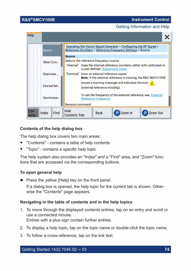
Instrument ControlR&S®SMCV100B
74Getting Started 1432.7046.02 ─ 03
Contents of the help dialog box
The help dialog box covers two main areas:● "Contents" - contains a table of help contents● "Topic" - contains a specific help topic
The help system also provides an "Index" and a "Find" area, and "Zoom" func-tions that are accessed via the corresponding buttons.
To open general help
► Press the yellow [Help] key on the front panel.If a dialog box is opened, the help topic for the current tab is shown. Other-wise the "Contents" page appears.
Navigating in the table of contents and in the help topics
1. To move through the displayed contents entries, tap on an entry and scroll oruse a connected mouse.Entries with a plus sign contain further entries.
2. To display a help topic, tap on the topic name or double-click the topic name.
3. To follow a cross-reference, tap on the link text.
Getting Information and Help

Instrument ControlR&S®SMCV100B
75Getting Started 1432.7046.02 ─ 03
4. To return to the previous page, select "Back".This function scrolls back all steps you have performed before.
5. Use the "scroll bars" to shift the visible section of content shown.
6. To maximize the "Topics" area, tap the "Hide Contents Tree" button to hide thecontents tree.
Using the index
1. Select the "Index" button.
2. Enter the first characters of the topic you are interested in.The entries starting with these characters are displayed.
3. Tap on the index entry.
The corresponding help topic is displayed.
8.7 Remote Control
In addition to working with the R&S SMCV100B interactively, located directly atthe instrument, it is also possible to operate and control it from a remote PC.
The R&S SMCV100B supports various methods for remote control:● Connecting the instrument to a LAN (see Chapter 4.7, "Connecting to LAN",
on page 19)● Using the LXI browser interface in a LAN
For remote control, you can use the R&S VISA (Virtual Instrument SoftwareArchitecture) library provided for download at the Rohde & Schwarz websitehttp://www.rohde-schwarz.com/rsvisa.
How to configure the remote control interfaces is described in the user manual,chapter "Network and Remote Control Operation".
Remote Control

Instrument ControlR&S®SMCV100B
76Getting Started 1432.7046.02 ─ 03
8.8 Remote Operation over VNC
The VNC is an application which can be used to access and control the instru-ment from a remote computer through a LAN connection. While the instrument isin operation, the instrument screen contents are displayed on the remote com-puter, and VNC provides access to all applications, files, and network resourcesof the instrument. Thus, remote operation of the instrument is possible.
Instrument control from a remote computerTo access the basic utility functions of the R&S SMCV100B, perform a rightmouse click the block diagram and select "Key Emulation".A key panel to the right of the block diagram gives access to the utility func-tions provided by the front panel keys.
The VNC is an add-on program, included in operating system Linux/Unix, andavailable as a free-of-charge download on the internet.
For more information, refer to the R&S SMCV100B user manual, chapter "How toSet Up Remote Operation via VNC".
Remote Operation over VNC

Contacting Customer SupportR&S®SMCV100B
77Getting Started 1432.7046.02 ─ 03
9 Contacting Customer SupportTechnical support – where and when you need it
For quick, expert help with any Rohde & Schwarz product, contact our customersupport center. A team of highly qualified engineers provides support and workswith you to find a solution to your query on any aspect of the operation, program-ming or applications of Rohde & Schwarz products.
Contact information
Contact our customer support center at www.rohde-schwarz.com/support, or fol-low this QR code:
Figure 9-1: QR code to the Rohde & Schwarz support page

IndexR&S®SMCV100B
78Getting Started 1432.7046.02 ─ 03
Index
A
Active elements ....................................... 68Alphanumeric parameters ....................... 73Application cards ..................................... 13Application notes ..................................... 13ARB ......................................................... 60
B
BasebandInput ....................................................60Output ................................................. 60
Baseband generator ................................ 60BB input ................................................... 60BB output .................................................60Bench top, placing ................................... 16Block diagram
Display ................................................ 66Brochures ................................................ 12
C
Carrying the instrument ........................... 15Checking the instrument ..........................15Connecting
Keyboard ............................................ 21LAN .....................................................19Memory stick .......................................21Monitor ................................................20Mouse ................................................. 21Power ..................................................19To Dig. IQ HS x ................................... 23To IP Data ........................................... 25To Ref In/Ref Out ................................ 23To RF .................................................. 22USB devices ....................................... 21
ConnectorAC power supply .................................33DVI-D .................................................. 33High-speed digital IQ .......................... 34IP data ................................................ 34LAN .....................................................34Ref In .................................................. 35Ref Out ............................................... 35RF 50 Ω .............................................. 32USB .............................................. 32, 34USER ..................................................34
Context-sensitive menu ........................... 68
Custom digital modulation ....................... 60Customer support .................................... 77
D
Data entry ................................................ 71Data sheets ............................................. 12Dialog boxes ............................................70Digital standard ....................................... 60Display
Active elements .................................. 68Block diagram ..................................... 66Context-sensitive menu ...................... 68Info line ............................................... 68Information ..........................................64On-screen keypad .............................. 68Status bar ........................................... 65Tab labels ............................................68Taskbar ............................................... 67
Documentation overview ......................... 11DVI-D .......................................................33
E
Emulating front panel keys ...................... 76External monitor
Connectors ......................................... 33
F
Firmware optionssee software options ...........................60
Front panelConnectors ......................................... 32Overview .............................................28
Function keysDetails - see user manual ................... 30Overview .............................................30
G
Getting started ......................................... 11
H
Head panelsee Status bar .....................................29
Headersee Status bar .....................................29
Help ................................................... 11, 73Hotspot .................................................... 67

IndexR&S®SMCV100B
79Getting Started 1432.7046.02 ─ 03
I
Info line .................................................... 68Input connector ........................................34Instrument
Carrying .............................................. 15Checking .............................................15Lifting .................................................. 15Operating site ............................... 15, 16Unpacking ...........................................15
Instrument control ....................................63Instrument help ........................................ 11Instrument security procedures ............... 12
K
Key★ (User) .............................................. 31Access on a remote computer ............ 76Emulation ............................................76Esc ......................................................31Freq/Level ...........................................31Help .................................................... 30Home .................................................. 31Mod On/Off ......................................... 31On/Off Toggle ......................................31On/Standby .........................................30Preset ................................................. 30RF on/off ............................................. 31Save/Rcl ............................................. 30
KeyboardOn-screen ........................................... 71Usage ................................................. 64
KeypadOn-screen ........................................... 71
L
LANConnecting ..........................................19Environment ........................................19
Lifting the instrument ............................... 15Loading
Trying out ............................................ 53
M
Manual interaction ................................... 64Mounting, in a rack .................................. 17Mouse
Usage ................................................. 64
N
NetworkEnvironment ........................................19
Numeric data entry .................................. 71Numeric parameters ................................ 72
O
On-screen keyboard ................................ 73On-screen keypad ................................... 68Open source acknowledgment (OSA) ..... 13Operating site
Choosing .............................................15Setting up the instrument ....................16
OperationManual ................................................ 64
Optionssee user manual ................................. 60
Output connector ..................................... 34Output connectors
RF 50 Ω .............................................. 32
P
ParametersEntering ........................................ 72, 73
Placing, on a bench top ........................... 16Power
Connecting the instrument ..................19Power on
Key ......................................................30Power supply
Connector ........................................... 33Preparing for use ..................................... 15
R
Rack, mounting ....................................... 17Rear panel
Overview .............................................32Release notes ......................................... 13Remote access
see Remote operation from a computer............................................................63
Remote control ........................................ 75Remote operation .................................... 76RF 50 Ω connector .................................. 32Rotary knob ............................................. 31
S
Safety instructions ................................... 12

IndexR&S®SMCV100B
80Getting Started 1432.7046.02 ─ 03
SavingTrying out ............................................ 52
Security procedures ................................ 12Serial number .......................................... 33Service manual ........................................12Softkey bar
see Taskbar ........................................ 67Software options ......................................60Standby
Key ......................................................30Status bar
Display ................................................ 65Switching
On or off .............................................. 26
T
Tab labels ................................................ 68Text entry ................................................. 71Tooltips
Show ...................................................73Touchscreen
Compared with mouse ........................64Overview .............................................29Usage ................................................. 64
U
Unpacking the instrument ........................15User manual ............................................ 11Utility keys
Details - see user manual ................... 30Overview .............................................30
V
VNCUsing in a LAN ....................................76
W
White papers ........................................... 13