Embed Size (px)
Citation preview
Data Sheet Version 10.00
Specifications
GNSS AND AVIONICS SIMULATION FOR ROHDE & SCHWARZ SIGNAL GENERATORS
R&S®SMBV100B Vector Signal Generator R&S®SMW200A Vector Signal Generator
Version 10.00, July 2020
Rohde & Schwarz GNSS and Avionics Simulation for Rohde & Schwarz Signal Generators 2
CONTENTS Definitions ....................................................................................................................................................................... 3
Overview .......................................................................................................................................................................... 4
Abbreviations ..................................................................................................................................................................................... 5
GNSS testing with the R&S®SMW200A ............................................................................................................................................. 5
Minimum instrument configuration for GNSS testing .......................................................................................................................... 6
Minimum instrument configuration for avionics testing ....................................................................................................................... 6
Global navigation satellite systems (GNSS) ................................................................................................................. 7
Addressed GNSS applications ........................................................................................................................................................... 7
Signals and systems .......................................................................................................................................................................... 8
Key features ...................................................................................................................................................................................... 9
Common specifications for all GNSS options ................................................................................................................................... 10
Specifications for GNSS options ...................................................................................................................................................... 13
Channel allocation ........................................................................................................................................................................... 20
Avionics systems .......................................................................................................................................................... 23
Key features .................................................................................................................................................................................... 23
Specifications for avionics options ................................................................................................................................................... 23
Ordering information .................................................................................................................................................... 28
R&S®SMBV100B ............................................................................................................................................................................. 28
R&S®SMW200A .............................................................................................................................................................................. 29
Version 10.00, July 2020
Rohde & Schwarz GNSS and Avionics Simulation for Rohde & Schwarz Signal Generators 3
Definitions General
Product data applies under the following conditions:
• Three hours storage at ambient temperature followed by 30 minutes warm-up operation
• Specified environmental conditions met
• Recommended calibration interval adhered to
• All internal automatic adjustments performed, if applicable
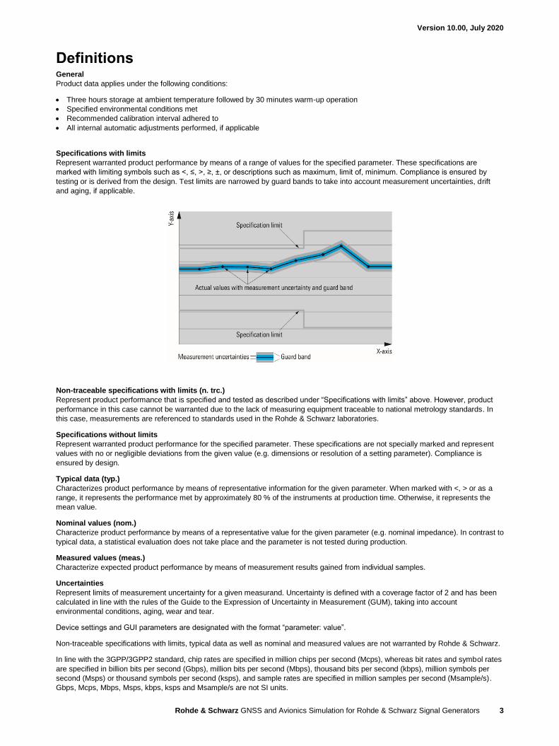
Specifications with limits
Represent warranted product performance by means of a range of values for the specified parameter. These specifications are
marked with limiting symbols such as <, ≤, >, ≥, ±, or descriptions such as maximum, limit of, minimum. Compliance is ensured by
testing or is derived from the design. Test limits are narrowed by guard bands to take into account measurement uncertainties, drift
and aging, if applicable.
Non-traceable specifications with limits (n. trc.)
Represent product performance that is specified and tested as described under “Specifications with limits” above. However, product
performance in this case cannot be warranted due to the lack of measuring equipment traceable to national metrology standards. In
this case, measurements are referenced to standards used in the Rohde & Schwarz laboratories.
Specifications without limits
Represent warranted product performance for the specified parameter. These specifications are not specially marked and represent
values with no or negligible deviations from the given value (e.g. dimensions or resolution of a setting parameter). Compliance is
ensured by design.
Typical data (typ.)
Characterizes product performance by means of representative information for the given parameter. When marked with <, > or as a
range, it represents the performance met by approximately 80 % of the instruments at production time. Otherwise, it represents the
mean value.
Nominal values (nom.)
Characterize product performance by means of a representative value for the given parameter (e.g. nominal impedance). In contrast to
typical data, a statistical evaluation does not take place and the parameter is not tested during production.
Measured values (meas.)
Characterize expected product performance by means of measurement results gained from individual samples.
Uncertainties
Represent limits of measurement uncertainty for a given measurand. Uncertainty is defined with a coverage factor of 2 and has been
calculated in line with the rules of the Guide to the Expression of Uncertainty in Measurement (GUM), taking into account
environmental conditions, aging, wear and tear.
Device settings and GUI parameters are designated with the format “parameter: value”.
Non-traceable specifications with limits, typical data as well as nominal and measured values are not warranted by Rohde & Schwarz.
In line with the 3GPP/3GPP2 standard, chip rates are specified in million chips per second (Mcps), whereas bit rates and symbol rates
are specified in billion bits per second (Gbps), million bits per second (Mbps), thousand bits per second (kbps), million symbols per
second (Msps) or thousand symbols per second (ksps), and sample rates are specified in million samples per second (Msample/s).
Gbps, Mcps, Mbps, Msps, kbps, ksps and Msample/s are not SI units.

Version 10.00, July 2020
Rohde & Schwarz GNSS and Avionics Simulation for Rohde & Schwarz Signal Generators 4
Overview With the GNSS and avionics simulation solutions for the R&S®SMBV100B and the R&S®SMW200A, dynamic scenarios with
GPS/SBAS/QZSS, Galileo, GLONASS and BeiDou signals can be generated in real-time including moving scenarios, multipath,
dynamic power control and atmospheric modeling. For moving scenarios, the effects of antenna pattern and vehicle body mask can be
simulated in real-time with dynamic variation of the vehicle’s attitude. Above and beyond GNSS signal generation, the
R&S®SMBV100B and the R&S®SMW200A are flexible vector signal generators with excellent RF performance. They offer options for
generating standard-compliant signals for all important digital communications standards (GSM, WCDMA, HSPA+, LTE, WiMAXTM,
WLAN, etc.). This versatility allows mobile phone or car infotainment system manufacturers that integrate GNSS modules into their
products to test the GNSS functionality and the normal functionality of their products with only one instrument.
This document contains the functional specifications of the GNSS-related software options for the R&S®SMBV100B and the
R&S®SMW200A:
Option R&S®SMBV100B R&S®SMW200A
GNSS
GPS R&S®SMBVB-K44 R&S®SMW-K44
Modernized GPS R&S®SMBVB-K98 R&S®SMW-K98
Galileo R&S®SMBVB-K66 R&S®SMW-K66
GLONASS R&S®SMBVB-K94 R&S®SMW-K94
BeiDou R&S®SMBVB-K107 R&S®SMW-K107
Modernized BeiDou R&S®SMBVB-K132 R&S®SMW-K132
SBAS/QZSS R&S®SMBVB-K106 R&S®SMW-K106
Real world scenarios R&S®SMBVB-K108 R&S®SMW-K108
Real-time GNSS interfaces R&S®SMBVB-K109 R&S®SMW-K109
Single-satellite GNSS R&S®SMBVB-K133 –
Upgrade to dual-frequency GNSS R&S®SMBVB-K134 R&S®SMW-K134
Upgrade to triple-frequency GNSS R&S®SMBVB-K135 R&S®SMW-K135
Add 6 GNSS channels R&S®SMBVB-K136 R&S®SMW-K136
Add 12 GNSS channels R&S®SMBVB-K137 R&S®SMW-K137
Add 24 GNSS channels – R&S®SMW-K138
Add 48 GNSS channels – R&S®SMW-K139
ERA-GLONASS test suite R&S®SMBVB-K360 R&S®SMW-K360
eCall test suite R&S®SMBVB-K361 R&S®SMW-K361
Extension to 48 GNSS channels per
baseband (in combination with
R&S®SMW-B10(F))
– R&S®SMW-K99
Advanced GNSS applications (in
combination with R&S®SMW-B10)
– R&S®SMW-K120
Avionics
GBAS R&S®SMBVB-K111 –
ILS R&S®SMBVB-K151 –
VOR R&S®SMBVB-K152 –
DME R&S®SMBVB-K153 –
For information on other digital standards or signal quality such as phase noise or spurious,
see the following Rohde & Schwarz documents:
• R&S®SMBV100B data sheet, PD 3607.8201.22 • R&S®SMBV100B product brochure, PD 3607.8201.12 • R&S®SMW200A data sheet, PD 5214.1114.22
• R&S®SMW200A product brochure, PD 5214.1114.12
• Digital standards for signal generators data sheet, PD 5213.9434.22
Version 10.00, July 2020
Rohde & Schwarz GNSS and Avionics Simulation for Rohde & Schwarz Signal Generators 5
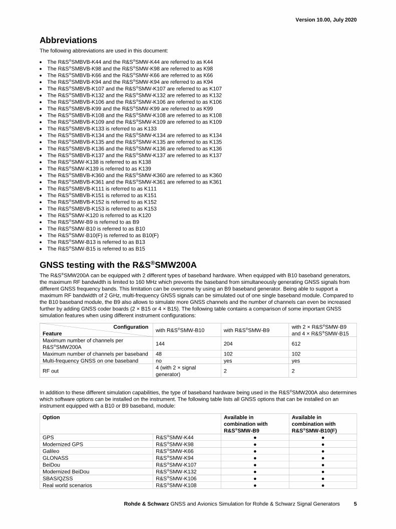
Abbreviations The following abbreviations are used in this document:
• The R&S®SMBVB-K44 and the R&S®SMW-K44 are referred to as K44
• The R&S®SMBVB-K98 and the R&S®SMW-K98 are referred to as K98
• The R&S®SMBVB-K66 and the R&S®SMW-K66 are referred to as K66
• The R&S®SMBVB-K94 and the R&S®SMW-K94 are referred to as K94
• The R&S®SMBVB-K107 and the R&S®SMW-K107 are referred to as K107
• The R&S®SMBVB-K132 and the R&S®SMW-K132 are referred to as K132
• The R&S®SMBVB-K106 and the R&S®SMW-K106 are referred to as K106
• The R&S®SMBVB-K99 and the R&S®SMW-K99 are referred to as K99
• The R&S®SMBVB-K108 and the R&S®SMW-K108 are referred to as K108
• The R&S®SMBVB-K109 and the R&S®SMW-K109 are referred to as K109
• The R&S®SMBVB-K133 is referred to as K133
• The R&S®SMBVB-K134 and the R&S®SMW-K134 are referred to as K134
• The R&S®SMBVB-K135 and the R&S®SMW-K135 are referred to as K135
• The R&S®SMBVB-K136 and the R&S®SMW-K136 are referred to as K136
• The R&S®SMBVB-K137 and the R&S®SMW-K137 are referred to as K137
• The R&S®SMW-K138 is referred to as K138
• The R&S®SMW-K139 is referred to as K139
• The R&S®SMBVB-K360 and the R&S®SMW-K360 are referred to as K360
• The R&S®SMBVB-K361 and the R&S®SMW-K361 are referred to as K361
• The R&S®SMBVB-K111 is referred to as K111
• The R&S®SMBVB-K151 is referred to as K151
• The R&S®SMBVB-K152 is referred to as K152
• The R&S®SMBVB-K153 is referred to as K153
• The R&S®SMW-K120 is referred to as K120
• The R&S®SMW-B9 is referred to as B9
• The R&S®SMW-B10 is referred to as B10
• The R&S®SMW-B10(F) is referred to as B10(F)
• The R&S®SMW-B13 is referred to as B13
• The R&S®SMW-B15 is referred to as B15
GNSS testing with the R&S®SMW200A The R&S®SMW200A can be equipped with 2 different types of baseband hardware. When equipped with B10 baseband generators,
the maximum RF bandwidth is limited to 160 MHz which prevents the baseband from simultaneously generating GNSS signals from
different GNSS frequency bands. This limitation can be overcome by using an B9 baseband generator. Being able to support a
maximum RF bandwidth of 2 GHz, multi-frequency GNSS signals can be simulated out of one single baseband module. Compared to
the B10 baseband module, the B9 also allows to simulate more GNSS channels and the number of channels can even be increased
further by adding GNSS coder boards (2 × B15 or 4 × B15). The following table contains a comparison of some important GNSS
simulation features when using different instrument configurations:
Configuration
Feature with R&S®SMW-B10 with R&S®SMW-B9
with 2 × R&S®SMW-B9
and 4 × R&S®SMW-B15
Maximum number of channels per
R&S®SMW200A 144 204 612
Maximum number of channels per baseband 48 102 102
Multi-frequency GNSS on one baseband no yes yes
RF out 4 (with 2 × signal
generator) 2 2
In addition to these different simulation capabilities, the type of baseband hardware being used in the R&S®SMW200A also determines
which software options can be installed on the instrument. The following table lists all GNSS options that can be installed on an
instrument equipped with a B10 or B9 baseband, module:
Option Available in
combination with
R&S®SMW-B9
Available in
combination with
R&S®SMW-B10(F)
GPS R&S®SMW-K44 ● ●
Modernized GPS R&S®SMW-K98 ● ●
Galileo R&S®SMW-K66 ● ●
GLONASS R&S®SMW-K94 ● ●
BeiDou R&S®SMW-K107 ● ●
Modernized BeiDou R&S®SMW-K132 ● ●
SBAS/QZSS R&S®SMW-K106 ● ●
Real world scenarios R&S®SMW-K108 ● ●
Version 10.00, July 2020
Rohde & Schwarz GNSS and Avionics Simulation for Rohde & Schwarz Signal Generators 6
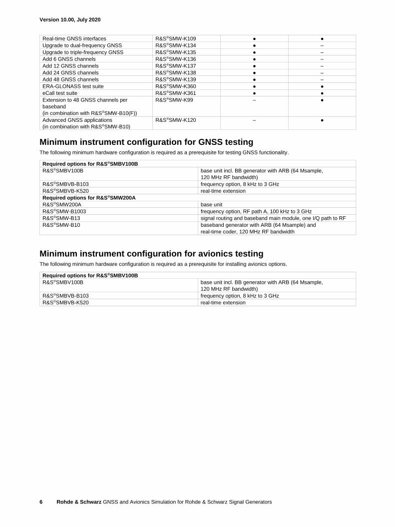
Real-time GNSS interfaces R&S®SMW-K109 ● ●
Upgrade to dual-frequency GNSS R&S®SMW-K134 ● –
Upgrade to triple-frequency GNSS R&S®SMW-K135 ● –
Add 6 GNSS channels R&S®SMW-K136 ● –
Add 12 GNSS channels R&S®SMW-K137 ● –
Add 24 GNSS channels R&S®SMW-K138 ● –
Add 48 GNSS channels R&S®SMW-K139 ● –
ERA-GLONASS test suite R&S®SMW-K360 ● ●
eCall test suite R&S®SMW-K361 ● ●
Extension to 48 GNSS channels per
baseband
(in combination with R&S®SMW-B10(F))
R&S®SMW-K99 – ●
Advanced GNSS applications
(in combination with R&S®SMW-B10)
R&S®SMW-K120 – ●
Minimum instrument configuration for GNSS testing The following minimum hardware configuration is required as a prerequisite for testing GNSS functionality.
Required options for R&S®SMBV100B
R&S®SMBV100B base unit incl. BB generator with ARB (64 Msample,
120 MHz RF bandwidth)
R&S®SMBVB-B103 frequency option, 8 kHz to 3 GHz
R&S®SMBVB-K520 real-time extension
Required options for R&S®SMW200A
R&S®SMW200A base unit
R&S®SMW-B1003 frequency option, RF path A, 100 kHz to 3 GHz
R&S®SMW-B13 signal routing and baseband main module, one I/Q path to RF
R&S®SMW-B10 baseband generator with ARB (64 Msample) and
real-time coder, 120 MHz RF bandwidth
Minimum instrument configuration for avionics testing The following minimum hardware configuration is required as a prerequisite for installing avionics options.
Required options for R&S®SMBV100B
R&S®SMBV100B base unit incl. BB generator with ARB (64 Msample,
120 MHz RF bandwidth)
R&S®SMBVB-B103 frequency option, 8 kHz to 3 GHz
R&S®SMBVB-K520 real-time extension
Version 10.00, July 2020
Rohde & Schwarz GNSS and Avionics Simulation for Rohde & Schwarz Signal Generators 7
Global navigation satellite systems (GNSS)
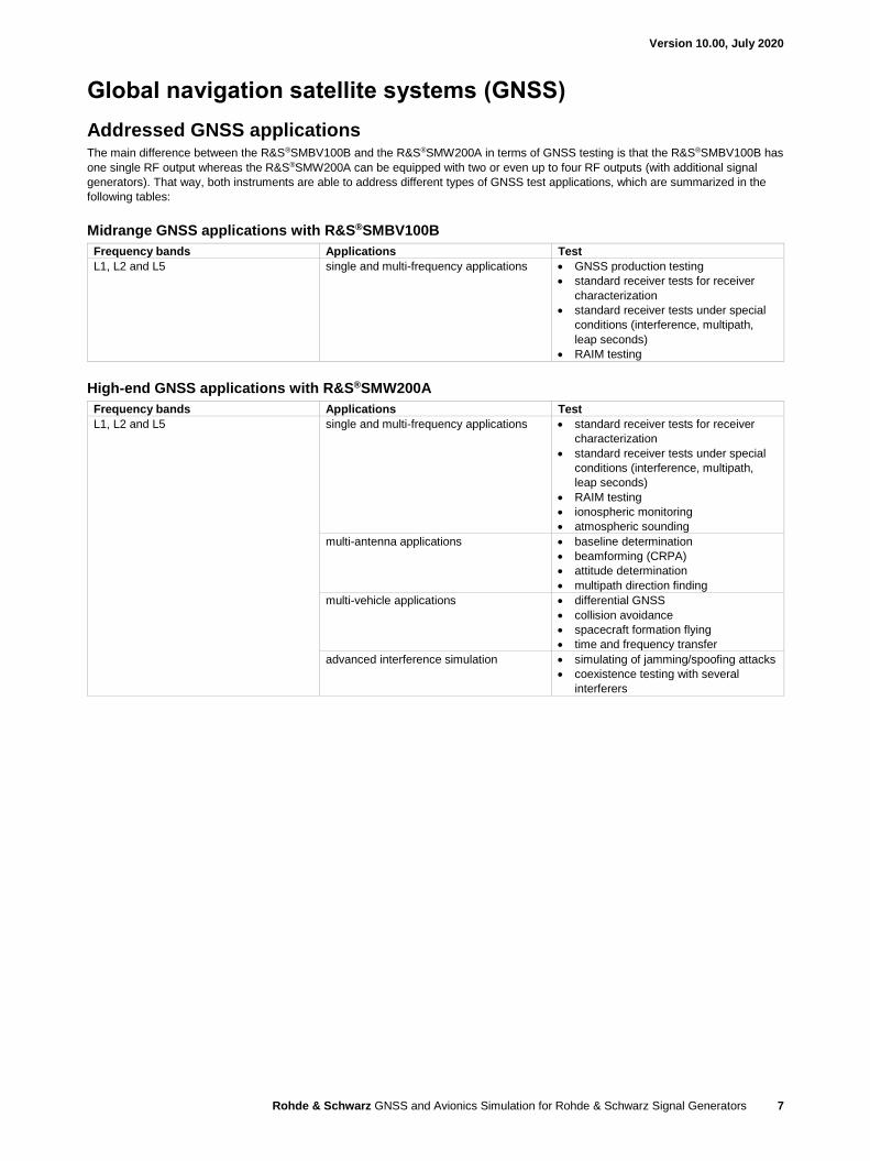
Addressed GNSS applications The main difference between the R&S®SMBV100B and the R&S®SMW200A in terms of GNSS testing is that the R&S®SMBV100B has
one single RF output whereas the R&S®SMW200A can be equipped with two or even up to four RF outputs (with additional signal
generators). That way, both instruments are able to address different types of GNSS test applications, which are summarized in the
following tables:
Midrange GNSS applications with R&S®SMBV100B
Frequency bands Applications Test
L1, L2 and L5 single and multi-frequency applications • GNSS production testing
• standard receiver tests for receiver
characterization
• standard receiver tests under special
conditions (interference, multipath,
leap seconds)
• RAIM testing
High-end GNSS applications with R&S®SMW200A
Frequency bands Applications Test
L1, L2 and L5 single and multi-frequency applications • standard receiver tests for receiver
characterization
• standard receiver tests under special
conditions (interference, multipath,
leap seconds)
• RAIM testing
• ionospheric monitoring
• atmospheric sounding
multi-antenna applications • baseline determination
• beamforming (CRPA)
• attitude determination
• multipath direction finding
multi-vehicle applications • differential GNSS
• collision avoidance
• spacecraft formation flying
• time and frequency transfer
advanced interference simulation • simulating of jamming/spoofing attacks
• coexistence testing with several
interferers
Version 10.00, July 2020
Rohde & Schwarz GNSS and Avionics Simulation for Rohde & Schwarz Signal Generators 8
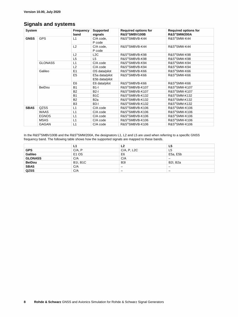
Signals and systems System Frequency
band
Supported
signals
Required options for
R&S®SMBV100B
Required options for
R&S®SMW200A
GNSS GPS L1 C/A code,
P code
R&S®SMBVB-K44 R&S®SMW-K44
L2 C/A code,
P code
R&S®SMBVB-K44 R&S®SMW-K44
L2 L2C R&S®SMBVB-K98 R&S®SMW-K98
L5 L5 R&S®SMBVB-K98 R&S®SMW-K98
GLONASS L1 C/A code R&S®SMBVB-K94 R&S®SMW-K94
L2 C/A code R&S®SMBVB-K94 R&S®SMW-K94
Galileo E1 OS data/pilot R&S®SMBVB-K66 R&S®SMW-K66
E5 E5a data/pilot
E5b data/pilot
R&S®SMBVB-K66 R&S®SMW-K66
E6 E6 data/pilot R&S®SMBVB-K66 R&S®SMW-K66
BeiDou B1 B1-I R&S®SMBVB-K107 R&S®SMW-K107
B2 B2-I R&S®SMBVB-K107 R&S®SMW-K107
B1 B1C R&S®SMBVB-K132 R&S®SMM-K132
B2 B2a R&S®SMBVB-K132 R&S®SMM-K132
B3 B3-I R&S®SMBVB-K132 R&S®SMM-K132
SBAS QZSS L1 C/A code R&S®SMBVB-K106 R&S®SMW-K106
WAAS L1 C/A code R&S®SMBVB-K106 R&S®SMW-K106
EGNOS L1 C/A code R&S®SMBVB-K106 R&S®SMW-K106
MSAS L1 C/A code R&S®SMBVB-K106 R&S®SMW-K106
GAGAN L1 C/A code R&S®SMBVB-K106 R&S®SMW-K106
In the R&S®SMBV100B and the R&S®SMW200A, the designators L1, L2 and L5 are used when referring to a specific GNSS
frequency band. The following table shows how the supported signals are mapped to these bands.
L1 L2 L5
GPS C/A, P C/A, P, L2C L5
Galileo E1 OS E6 E5a, E5b
GLONASS C/A C/A –
BeiDou B1I, B1C B3I B2I, B2a
SBAS C/A – –
QZSS C/A – –
Version 10.00, July 2020
Rohde & Schwarz GNSS and Avionics Simulation for Rohde & Schwarz Signal Generators 9
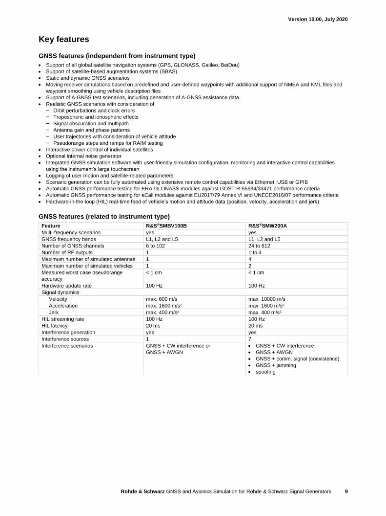
Key features
GNSS features (independent from instrument type)
• Support of all global satellite navigation systems (GPS, GLONASS, Galileo, BeiDou)
• Support of satellite-based augmentation systems (SBAS)
• Static and dynamic GNSS scenarios
• Moving receiver simulations based on predefined and user-defined waypoints with additional support of NMEA and KML files and
waypoint smoothing using vehicle description files
• Support of A-GNSS test scenarios, including generation of A-GNSS assistance data
• Realistic GNSS scenarios with consideration of
− Orbit perturbations and clock errors
− Tropospheric and ionospheric effects
− Signal obscuration and multipath
− Antenna gain and phase patterns
− User trajectories with consideration of vehicle attitude
− Pseudorange steps and ramps for RAIM testing
• Interactive power control of individual satellites
• Optional internal noise generator
• Integrated GNSS simulation software with user-friendly simulation configuration, monitoring and interactive control capabilities
using the instrument’s large touchscreen
• Logging of user motion and satellite-related parameters
• Scenario generation can be fully automated using extensive remote control capabilities via Ethernet, USB or GPIB
• Automatic GNSS performance testing for ERA-GLONASS modules against GOST-R-55534/33471 performance criteria
• Automatic GNSS performance testing for eCall modules against EU2017/79 Annex VI and UNECE2016/07 performance criteria
• Hardware-in-the-loop (HIL) real-time feed of vehicle’s motion and attitude data (position, velocity, acceleration and jerk)
GNSS features (related to instrument type)
Feature R&S®SMBV100B R&S®SMW200A
Multi-frequency scenarios yes yes
GNSS frequency bands L1, L2 and L5 L1, L2 and L5
Number of GNSS channels 6 to 102 24 to 612
Number of RF outputs 1 1 to 4
Maximum number of simulated antennas 1 4
Maximum number of simulated vehicles 1 2
Measured worst case pseudorange
accuracy
< 1 cm < 1 cm
Hardware update rate 100 Hz 100 Hz
Signal dynamics
Velocity max. 600 m/s max. 10000 m/s
Acceleration max. 1600 m/s² max. 1600 m/s²
Jerk max. 400 m/s³ max. 400 m/s³
HIL streaming rate 100 Hz 100 Hz
HIL latency 20 ms 20 ms
Interference generation yes yes
Interference sources 1 7
Interference scenarios GNSS + CW interference or
GNSS + AWGN
• GNSS + CW interference
• GNSS + AWGN
• GNSS + comm. signal (coexistence)
• GNSS + jamming
• spoofing
Version 10.00, July 2020
Rohde & Schwarz GNSS and Avionics Simulation for Rohde & Schwarz Signal Generators 10
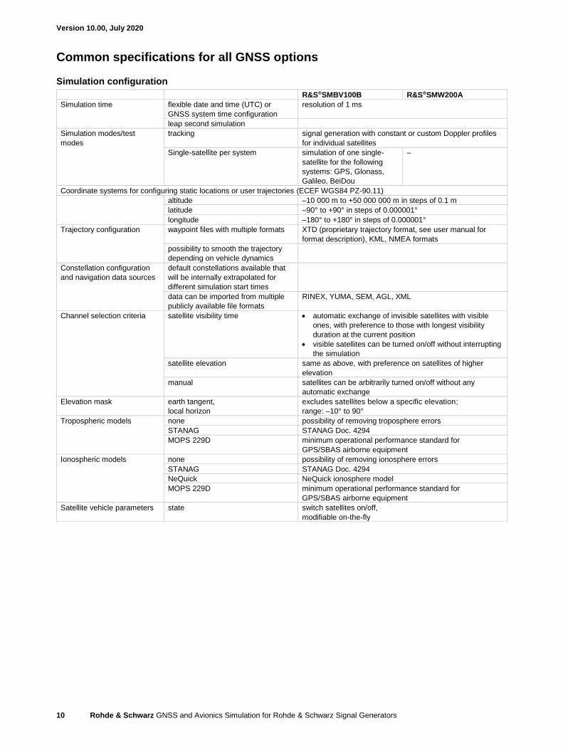
Common specifications for all GNSS options
Simulation configuration
R&S®SMBV100B R&S®SMW200A
Simulation time flexible date and time (UTC) or
GNSS system time configuration
resolution of 1 ms
leap second simulation
Simulation modes/test
modes
tracking signal generation with constant or custom Doppler profiles
for individual satellites
Single-satellite per system simulation of one single-
satellite for the following
systems: GPS, Glonass,
Galileo, BeiDou
–
Coordinate systems for configuring static locations or user trajectories (ECEF WGS84 PZ-90.11)
altitude –10 000 m to +50 000 000 m in steps of 0.1 m
latitude –90° to +90° in steps of 0.000001°
longitude –180° to +180° in steps of 0.000001°
Trajectory configuration waypoint files with multiple formats XTD (proprietary trajectory format, see user manual for
format description), KML, NMEA formats
possibility to smooth the trajectory
depending on vehicle dynamics
Constellation configuration
and navigation data sources
default constellations available that
will be internally extrapolated for
different simulation start times
data can be imported from multiple
publicly available file formats
RINEX, YUMA, SEM, AGL, XML
Channel selection criteria satellite visibility time • automatic exchange of invisible satellites with visible
ones, with preference to those with longest visibility
duration at the current position
• visible satellites can be turned on/off without interrupting
the simulation
satellite elevation same as above, with preference on satellites of higher
elevation
manual satellites can be arbitrarily turned on/off without any
automatic exchange
Elevation mask earth tangent,
local horizon
excludes satellites below a specific elevation;
range: –10° to 90°
Tropospheric models none possibility of removing troposphere errors
STANAG STANAG Doc. 4294
MOPS 229D minimum operational performance standard for
GPS/SBAS airborne equipment
Ionospheric models none possibility of removing ionosphere errors
STANAG STANAG Doc. 4294
NeQuick NeQuick ionosphere model
MOPS 229D minimum operational performance standard for
GPS/SBAS airborne equipment
Satellite vehicle parameters state switch satellites on/off,
modifiable on-the-fly
Version 10.00, July 2020
Rohde & Schwarz GNSS and Avionics Simulation for Rohde & Schwarz Signal Generators 11
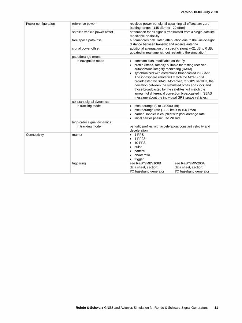
Power configuration reference power received power per signal assuming all offsets are zero
(setting range: –145 dBm to –20 dBm)
satellite vehicle power offset attenuation for all signals transmitted from a single-satellite,
modifiable on-the-fly
free space path-loss automatically calculated attenuation due to the line-of-sight
distance between transmit and receive antenna
signal power offset additional attenuation of a specific signal (–21 dB to 0 dB,
updated in real-time without restarting the simulation)
pseudorange errors
in navigation mode • constant bias, modifiable on-the-fly
• profile (steps, ramps): suitable for testing receiver
autonomous integrity monitoring (RAIM)
• synchronized with corrections broadcasted in SBAS:
The ionosphere errors will match the MOPS grid
broadcasted by SBAS. Moreover, for GPS satellite, the
deviation between the simulated orbits and clock and
those broadcasted by the satellites will match the
amount of differential correction broadcasted in SBAS
message about the individual GPS space vehicles.
constant signal dynamics
in tracking mode • pseudorange (0 to 119900 km)
• pseudorange rate (–100 km/s to 100 km/s)
• carrier Doppler is coupled with pseudorange rate
• initial carrier phase: 0 to 2π rad
high-order signal dynamics
in tracking mode periodic profiles with acceleration, constant velocity and
deceleration
Connectivity marker • 1 PPS
• 1 PP2S
• 10 PPS
• pulse
• pattern
• on/off ratio
• trigger
triggering see R&S®SMBV100B
data sheet, section:
I/Q baseband generator
see R&S®SMW200A
data sheet, section:
I/Q baseband generator
Version 10.00, July 2020
Rohde & Schwarz GNSS and Avionics Simulation for Rohde & Schwarz Signal Generators 12
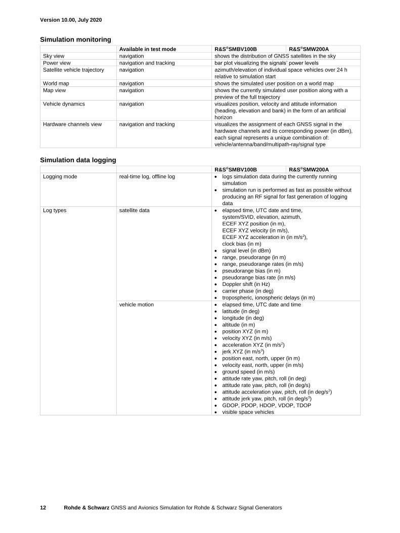
Simulation monitoring
Available in test mode R&S®SMBV100B R&S®SMW200A
Sky view navigation shows the distribution of GNSS satellites in the sky
Power view navigation and tracking bar plot visualizing the signals’ power levels
Satellite vehicle trajectory navigation azimuth/elevation of individual space vehicles over 24 h
relative to simulation start
World map navigation shows the simulated user position on a world map
Map view navigation shows the currently simulated user position along with a
preview of the full trajectory
Vehicle dynamics navigation visualizes position, velocity and attitude information
(heading, elevation and bank) in the form of an artificial
horizon
Hardware channels view navigation and tracking visualizes the assignment of each GNSS signal in the
hardware channels and its corresponding power (in dBm),
each signal represents a unique combination of:
vehicle/antenna/band/multipath-ray/signal type
Simulation data logging
R&S®SMBV100B R&S®SMW200A
Logging mode real-time log, offline log • logs simulation data during the currently running
simulation
• simulation run is performed as fast as possible without
producing an RF signal for fast generation of logging
data
Log types satellite data • elapsed time, UTC date and time,
system/SVID, elevation, azimuth,
ECEF XYZ position (in m),
ECEF XYZ velocity (in m/s),
ECEF XYZ acceleration in (in m/s2),
clock bias (in m)
• signal level (in dBm)
• range, pseudorange (in m)
• range, pseudorange rates (in m/s)
• pseudorange bias (in m)
• pseudorange bias rate (in m/s)
• Doppler shift (in Hz)
• carrier phase (in deg)
• tropospheric, ionospheric delays (in m)
vehicle motion • elapsed time, UTC date and time
• latitude (in deg)
• longitude (in deg)
• altitude (in m)
• position XYZ (in m)
• velocity XYZ (in m/s)
• acceleration XYZ (in m/s2)
• jerk XYZ (in m/s3)
• position east, north, upper (in m)
• velocity east, north, upper (in m/s)
• ground speed (in m/s)
• attitude rate yaw, pitch, roll (in deg)
• attitude rate yaw, pitch, roll (in deg/s)
• attitude acceleration yaw, pitch, roll (in deg/s2)
• attitude jerk yaw, pitch, roll (in deg/s3)
• GDOP, PDOP, HDOP, VDOP, TDOP
• visible space vehicles
Version 10.00, July 2020
Rohde & Schwarz GNSS and Avionics Simulation for Rohde & Schwarz Signal Generators 13
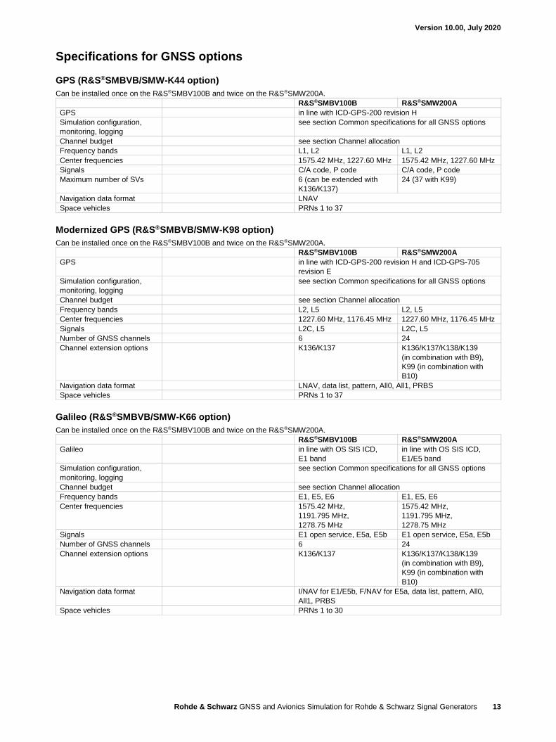
Specifications for GNSS options
GPS (R&S®SMBVB/SMW-K44 option)
Can be installed once on the R&S®SMBV100B and twice on the R&S®SMW200A.
R&S®SMBV100B R&S®SMW200A
GPS in line with ICD-GPS-200 revision H
Simulation configuration,
monitoring, logging
see section Common specifications for all GNSS options
Channel budget see section Channel allocation
Frequency bands L1, L2 L1, L2
Center frequencies 1575.42 MHz, 1227.60 MHz 1575.42 MHz, 1227.60 MHz
Signals C/A code, P code C/A code, P code
Maximum number of SVs 6 (can be extended with
K136/K137)
24 (37 with K99)
Navigation data format LNAV
Space vehicles PRNs 1 to 37
Modernized GPS (R&S®SMBVB/SMW-K98 option)
Can be installed once on the R&S®SMBV100B and twice on the R&S®SMW200A.
R&S®SMBV100B R&S®SMW200A
GPS in line with ICD-GPS-200 revision H and ICD-GPS-705
revision E
Simulation configuration,
monitoring, logging
see section Common specifications for all GNSS options
Channel budget see section Channel allocation
Frequency bands L2, L5 L2, L5
Center frequencies 1227.60 MHz, 1176.45 MHz 1227.60 MHz, 1176.45 MHz
Signals L2C, L5 L2C, L5
Number of GNSS channels 6 24
Channel extension options K136/K137 K136/K137/K138/K139
(in combination with B9),
K99 (in combination with
B10)
Navigation data format LNAV, data list, pattern, All0, All1, PRBS
Space vehicles PRNs 1 to 37
Galileo (R&S®SMBVB/SMW-K66 option)
Can be installed once on the R&S®SMBV100B and twice on the R&S®SMW200A.
R&S®SMBV100B R&S®SMW200A
Galileo in line with OS SIS ICD,
E1 band
in line with OS SIS ICD,
E1/E5 band
Simulation configuration,
monitoring, logging
see section Common specifications for all GNSS options
Channel budget see section Channel allocation
Frequency bands E1, E5, E6 E1, E5, E6
Center frequencies 1575.42 MHz,
1191.795 MHz,
1278.75 MHz
1575.42 MHz,
1191.795 MHz,
1278.75 MHz
Signals E1 open service, E5a, E5b E1 open service, E5a, E5b
Number of GNSS channels 6 24
Channel extension options K136/K137 K136/K137/K138/K139
(in combination with B9),
K99 (in combination with
B10)
Navigation data format I/NAV for E1/E5b, F/NAV for E5a, data list, pattern, All0,
All1, PRBS
Space vehicles PRNs 1 to 30
Version 10.00, July 2020
Rohde & Schwarz GNSS and Avionics Simulation for Rohde & Schwarz Signal Generators 14
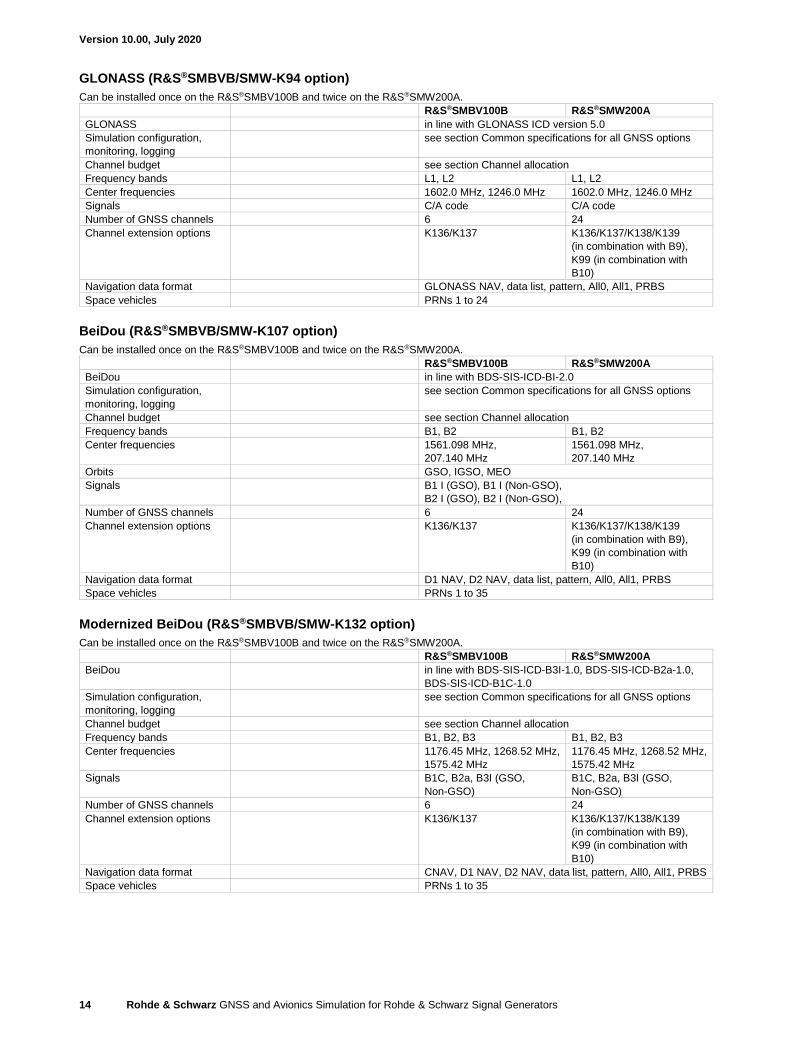
GLONASS (R&S®SMBVB/SMW-K94 option)
Can be installed once on the R&S®SMBV100B and twice on the R&S®SMW200A.
R&S®SMBV100B R&S®SMW200A
GLONASS in line with GLONASS ICD version 5.0
Simulation configuration,
monitoring, logging
see section Common specifications for all GNSS options
Channel budget see section Channel allocation
Frequency bands L1, L2 L1, L2
Center frequencies 1602.0 MHz, 1246.0 MHz 1602.0 MHz, 1246.0 MHz
Signals C/A code C/A code
Number of GNSS channels 6 24
Channel extension options K136/K137 K136/K137/K138/K139
(in combination with B9),
K99 (in combination with
B10)
Navigation data format GLONASS NAV, data list, pattern, All0, All1, PRBS
Space vehicles PRNs 1 to 24
BeiDou (R&S®SMBVB/SMW-K107 option)
Can be installed once on the R&S®SMBV100B and twice on the R&S®SMW200A.
R&S®SMBV100B R&S®SMW200A
BeiDou in line with BDS-SIS-ICD-BI-2.0
Simulation configuration,
monitoring, logging
see section Common specifications for all GNSS options
Channel budget see section Channel allocation
Frequency bands B1, B2 B1, B2
Center frequencies 1561.098 MHz,
207.140 MHz
1561.098 MHz,
207.140 MHz
Orbits GSO, IGSO, MEO
Signals B1 I (GSO), B1 I (Non-GSO),
B2 I (GSO), B2 I (Non-GSO),
Number of GNSS channels 6 24
Channel extension options K136/K137 K136/K137/K138/K139
(in combination with B9),
K99 (in combination with
B10)
Navigation data format D1 NAV, D2 NAV, data list, pattern, All0, All1, PRBS
Space vehicles PRNs 1 to 35
Modernized BeiDou (R&S®SMBVB/SMW-K132 option)
Can be installed once on the R&S®SMBV100B and twice on the R&S®SMW200A.
R&S®SMBV100B R&S®SMW200A
BeiDou in line with BDS-SIS-ICD-B3I-1.0, BDS-SIS-ICD-B2a-1.0,
BDS-SIS-ICD-B1C-1.0
Simulation configuration,
monitoring, logging
see section Common specifications for all GNSS options
Channel budget see section Channel allocation
Frequency bands B1, B2, B3 B1, B2, B3
Center frequencies 1176.45 MHz, 1268.52 MHz,
1575.42 MHz
1176.45 MHz, 1268.52 MHz,
1575.42 MHz
Signals B1C, B2a, B3I (GSO,
Non-GSO)
B1C, B2a, B3I (GSO,
Non-GSO)
Number of GNSS channels 6 24
Channel extension options K136/K137 K136/K137/K138/K139
(in combination with B9),
K99 (in combination with
B10)
Navigation data format CNAV, D1 NAV, D2 NAV, data list, pattern, All0, All1, PRBS
Space vehicles PRNs 1 to 35
Version 10.00, July 2020
Rohde & Schwarz GNSS and Avionics Simulation for Rohde & Schwarz Signal Generators 15
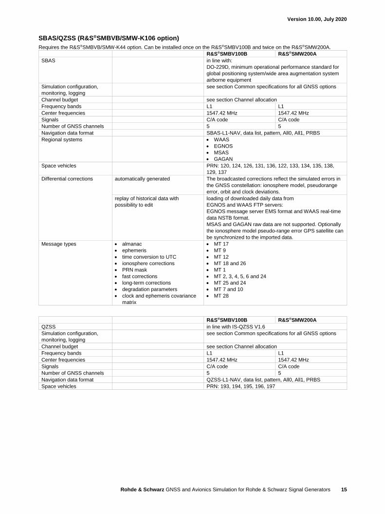
SBAS/QZSS (R&S®SMBVB/SMW-K106 option)
Requires the R&S®SMBVB/SMW-K44 option. Can be installed once on the R&S®SMBV100B and twice on the R&S®SMW200A.
R&S®SMBV100B R&S®SMW200A
SBAS in line with:
DO-229D, minimum operational performance standard for
global positioning system/wide area augmentation system
airborne equipment
Simulation configuration,
monitoring, logging
see section Common specifications for all GNSS options
Channel budget see section Channel allocation
Frequency bands L1 L1
Center frequencies 1547.42 MHz 1547.42 MHz
Signals C/A code C/A code
Number of GNSS channels 5 5
Navigation data format SBAS-L1-NAV, data list, pattern, All0, All1, PRBS
Regional systems • WAAS
• EGNOS
• MSAS
• GAGAN
Space vehicles PRN: 120, 124, 126, 131, 136, 122, 133, 134, 135, 138,
129, 137
Differential corrections automatically generated The broadcasted corrections reflect the simulated errors in
the GNSS constellation: ionosphere model, pseudorange
error, orbit and clock deviations.
replay of historical data with
possibility to edit
loading of downloaded daily data from
EGNOS and WAAS FTP servers:
EGNOS message server EMS format and WAAS real-time
data NSTB format.
MSAS and GAGAN raw data are not supported. Optionally
the ionosphere model pseudo-range error GPS satellite can
be synchronized to the imported data.
Message types • almanac
• ephemeris
• time conversion to UTC
• ionosphere corrections
• PRN mask
• fast corrections
• long-term corrections
• degradation parameters
• clock and ephemeris covariance
matrix
• MT 17
• MT 9
• MT 12
• MT 18 and 26
• MT 1
• MT 2, 3, 4, 5, 6 and 24
• MT 25 and 24
• MT 7 and 10
• MT 28
R&S®SMBV100B R&S®SMW200A
QZSS in line with IS-QZSS V1.6
Simulation configuration,
monitoring, logging
see section Common specifications for all GNSS options
Channel budget see section Channel allocation
Frequency bands L1 L1
Center frequencies 1547.42 MHz 1547.42 MHz
Signals C/A code C/A code
Number of GNSS channels 5 5
Navigation data format QZSS-L1-NAV, data list, pattern, All0, All1, PRBS
Space vehicles PRN: 193, 194, 195, 196, 197
Version 10.00, July 2020
Rohde & Schwarz GNSS and Avionics Simulation for Rohde & Schwarz Signal Generators 16
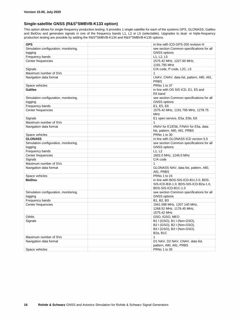
Single-satellite GNSS (R&S®SMBVB-K133 option)
This option allows for single-frequency production testing. It provides 1 single-satellite for each of the systems GPS, GLONASS, Galileo
and BeiDou and generates signals in one of the frequency bands L1, L2 or L5 (selectable). Upgrades to dual- or triple-frequency
production testing are possible by adding the R&S®SMBVB-K134 and R&S®SMBVB-K135 options.
GPS in line with ICD-GPS-200 revision H
Simulation configuration, monitoring,
logging
see section Common specifications for all
GNSS options
Frequency bands L1, L2, L5
Center frequencies 1575.42 MHz, 1227.60 MHz,
1191.795 MHz
Signals C/A code, P code, L2C, L5
Maximum number of SVs 1
Navigation data format LNAV, CNAV, data list, pattern, All0, All1,
PRBS
Space vehicles PRNs 1 to 37
Galileo in line with OS SIS ICD, E1, E5 and
E6 band
Simulation configuration, monitoring,
logging
see section Common specifications for all
GNSS options
Frequency bands E1, E5, E6
Center frequencies 1575.42 MHz, 1191.795 MHz, 1278.75
MHz
Signals E1 open service, E5a, E5b, E6
Maximum number of SVs 1
Navigation data format I/NAV for E1/E5b, F/NAV for E5a, data
list, pattern, All0, All1, PRBS
Space vehicles PRNs 1 to 30
GLONASS in line with GLONASS ICD version 5.0
Simulation configuration, monitoring,
logging
see section Common specifications for all
GNSS options
Frequency bands L1, L2
Center frequencies 1602.0 MHz, 1246.0 MHz
Signals C/A code
Maximum number of SVs 1
Navigation data format GLONASS NAV, data list, pattern, All0,
All1, PRBS
Space vehicles PRNs 1 to 24
BeiDou in line with BDS-SIS-ICD-B1I-2.0, BDS-
SIS-ICD-B3I-1.0, BDS-SIS-ICD-B2a-1.0,
BDS-SIS-ICD-B1C-1.0
Simulation configuration, monitoring,
logging
see section Common specifications for all
GNSS options
Frequency bands B1, B2, B3
Center frequencies 1561.098 MHz, 1207.140 MHz,
1268.52 MHz, 1176.45 MHz,
1575.42 MHz
Orbits GSO, IGSO, MEO
Signals B1 I (GSO), B1 I (Non-GSO),
B2 I (GSO), B2 I (Non-GSO),
B3 I (GSO), B3 I (Non-GSO),
B2a, B1C
Maximum number of SVs 1
Navigation data format D1 NAV, D2 NAV, CNAV, data list,
pattern, All0, All1, PRBS
Space vehicles PRNs 1 to 35
Version 10.00, July 2020
Rohde & Schwarz GNSS and Avionics Simulation for Rohde & Schwarz Signal Generators 17
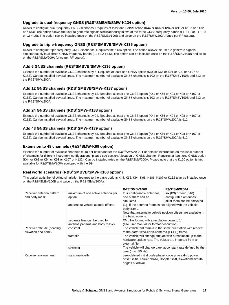
Upgrade to dual-frequency GNSS (R&S®SMBVB/SMW-K134 option)
Allows to configure dual-frequency GNSS scenarios. Requires at least one GNSS option (K44 or K66 or K94 or K98 or K107 or K132
or K133). The option allows the user to generate signals simultaneously in two of the three GNSS frequency bands (L1 + L2 or L1 + L5
or L2 + L5). The option can be installed once on the R&S®SMBV100B and twice on the R&S®SMW200A (once per RF output).
Upgrade to triple-frequency GNSS (R&S®SMBVB/SMW-K135 option)
Allows to configure triple-frequency GNSS scenarios. Requires the K134 option. The option allows the user to generate signals
simultaneously in all three GNSS frequency bands (L1 + L2 + L5). The option can be installed once on the R&S®SMBV100B and twice
on the R&S®SMW200A (once per RF output).
Add 6 GNSS channels (R&S®SMBVB/SMW-K136 option)
Extends the number of available GNSS channels by 6. Requires at least one GNSS option (K44 or K66 or K94 or K98 or K107 or
K132). Can be installed several times. The maximum number of available GNSS channels is 102 on the R&S®SMBV100B and 612 on
the R&S®SMW200A.
Add 12 GNSS channels (R&S®SMBVB/SMW-K137 option)
Extends the number of available GNSS channels by 12. Requires at least one GNSS option (K44 or K66 or K94 or K98 or K107 or
K132). Can be installed several times. The maximum number of available GNSS channels is 102 on the R&S®SMBV100B and 612 on
the R&S®SMW200A.
Add 24 GNSS channels (R&S®SMW-K138 option)
Extends the number of available GNSS channels by 24. Requires at least one GNSS option (K44 or K66 or K94 or K98 or K107 or
K132). Can be installed several times. The maximum number of available GNSS channels on the R&S®SMW200A is 612.
Add 48 GNSS channels (R&S®SMW-K139 option)
Extends the number of available GNSS channels by 48. Requires at least one GNSS option (K44 or K66 or K94 or K98 or K107 or
K132). Can be installed several times. The maximum number of available GNSS channels on the R&S®SMW200A is 612.
Extension to 48 channels (R&S®SMW-K99 option)
Extends the number of available channels to 48 per baseband for the R&S®SMW200A. For detailed information on available number
of channels for different instrument configurations, please see section Allocation of GNSS channel. Requires at least one GNSS option
(K44 or K66 or K94 or K98 or K107 or K132). Can be installed twice on the R&S®SMW200A. Please note that the K120 option is not
available for R&S®SMW200A equipped with the B9.
Real world scenarios (R&S®SMBVB/SMW-K108 option)
This option adds the following simulation features to the basic options K44, K66, K94, K98, K106, K107 or K132 (can be installed once
on the R&S®SMBV100B and twice on the R&S®SMW200A).
R&S®SMBV100B R&S®SMW200A
Receiver antenna pattern
and body mask
maximum of one active antenna per
option
four configurable antennas,
one of them can be
simulated
six (B9) or four (B10)
configurable antennas,
all of them can be activated
antenna to vehicle attitude offsets E.g. if the antenna frame is not aligned with the vehicle
body frame.
Note that antenna to vehicle position offsets are available in
the basic options.
separate files can be used for
antenna patterns and body masks
XML file format with a resolution down to 1°
(see user manual for format description)
Receiver attitude (heading,
elevation and bank)
constant The vehicle will remain in the same orientation with respect
to the earth-fixed-earth-centered (ECEF) frame.
from file The vehicle will change attitude with a resolution up to the
hardware update rate. The values are imported from an
external file.
spinning The vehicle will change bank at constant rate defined by the
user (max. 50 Hz).
Receiver environment static multipath user-defined initial code phase, code phase drift, power
offset, initial carrier phase, Doppler shift, elevation/azimuth
angles of arrival
Version 10.00, July 2020
Rohde & Schwarz GNSS and Avionics Simulation for Rohde & Schwarz Signal Generators 18
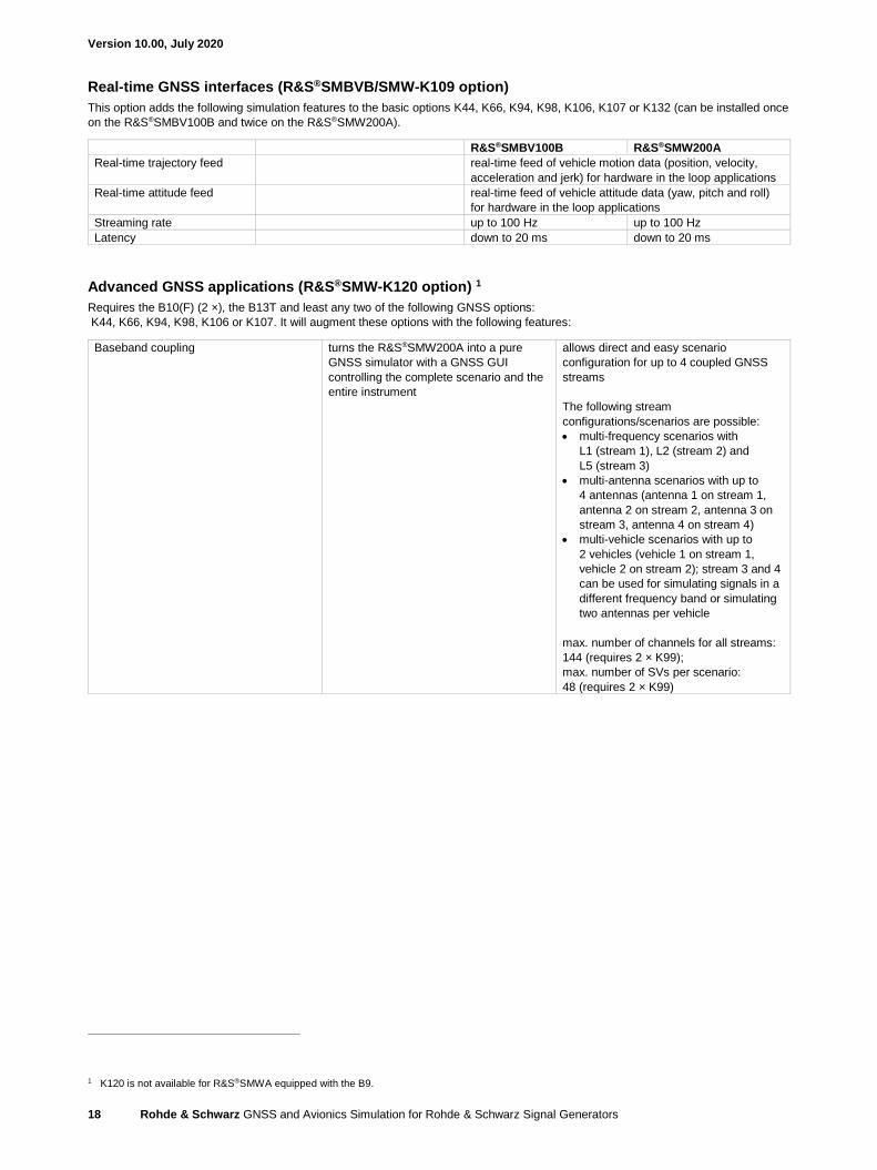
Real-time GNSS interfaces (R&S®SMBVB/SMW-K109 option)
This option adds the following simulation features to the basic options K44, K66, K94, K98, K106, K107 or K132 (can be installed once
on the R&S®SMBV100B and twice on the R&S®SMW200A).
R&S®SMBV100B R&S®SMW200A
Real-time trajectory feed real-time feed of vehicle motion data (position, velocity,
acceleration and jerk) for hardware in the loop applications
Real-time attitude feed real-time feed of vehicle attitude data (yaw, pitch and roll)
for hardware in the loop applications
Streaming rate up to 100 Hz up to 100 Hz
Latency down to 20 ms down to 20 ms
Advanced GNSS applications (R&S®SMW-K120 option) 1
Requires the B10(F) (2 ×), the B13T and least any two of the following GNSS options:
K44, K66, K94, K98, K106 or K107. It will augment these options with the following features:
Baseband coupling turns the R&S®SMW200A into a pure
GNSS simulator with a GNSS GUI
controlling the complete scenario and the
entire instrument
allows direct and easy scenario
configuration for up to 4 coupled GNSS
streams
The following stream
configurations/scenarios are possible:
• multi-frequency scenarios with
L1 (stream 1), L2 (stream 2) and
L5 (stream 3)
• multi-antenna scenarios with up to
4 antennas (antenna 1 on stream 1,
antenna 2 on stream 2, antenna 3 on
stream 3, antenna 4 on stream 4)
• multi-vehicle scenarios with up to
2 vehicles (vehicle 1 on stream 1,
vehicle 2 on stream 2); stream 3 and 4
can be used for simulating signals in a
different frequency band or simulating
two antennas per vehicle
max. number of channels for all streams:
144 (requires 2 × K99);
max. number of SVs per scenario:
48 (requires 2 × K99)
1 K120 is not available for R&S®SMWA equipped with the B9.
Version 10.00, July 2020
Rohde & Schwarz GNSS and Avionics Simulation for Rohde & Schwarz Signal Generators 19
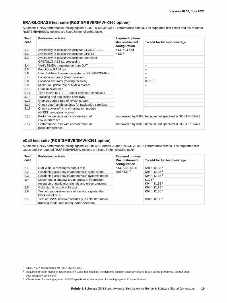
ERA-GLONASS test suite (R&S®SMBVB/SMW-K360 option)
Automatic GNSS performance testing against GOST-R-55534/33471 performance criteria. The supported test cases and the required
R&S®SMBVB/SMW options are listed in the following table:
Test
case
Performance tests Required options
Min. instrument
configuration
To add for full test coverage
5.1 Availability of position/velocity for GLONASS L1 K44, K94 and
K137 2
–
5.2 Availability of position/velocity for GPS L1 –
5.3 Availability of position/velocity for combined
GPS/GLONASS L1 processing –
5.4 Verify NMEA transmission from DUT –
5.5 Functional RAIM test –
5.6 Use of different reference systems (PZ-90/WGS-84) –
5.7 Location accuracy (static receiver) –
5.8 Location accuracy (moving receiver) K108 3
5.9 Minimum update rate of NMEA stream –
5.10 Reacquisition time –
5.11 Time to first fix (TTFF) under cold start conditions –
5.12 Tracking and acquisition sensitivity –
5.13 Change update rate of NMEA stream –
5.14 Check cutoff angle settings for navigation satellites –
5.15 Check power-off time of navigation module
(GNSS navigation receiver)
5.16 Performance tests with consideration of
CW interference
not covered by K360, because not specified in GOST-R-33471
5.17 Performance tests with consideration of
pulse interference
not covered by K360, because not specified in GOST-R-33471
eCall test suite (R&S®SMBVB/SMW-K361 option)
Automatic GNSS performance testing against EU2017/79, Annex VI and UNECE 2016/07 performance criteria. The supported test
cases and the required R&S®SMBVB/SMW options are listed in the following table:
Test
case
Performance tests Required options
Min. instrument
configuration
To add for full test coverage
2.1 NMEA-0183 messages output test K44, K66, K106
and K137 2
K94 4, K136 1
2.2 Positioning accuracy in autonomous static mode K94 4, K136 1
2.3 Positioning accuracy in autonomous dynamic mode K94 4, K136 1
2.4 Movement in shadow areas, areas of intermittent
reception of navigation signals and urban canyons
K108 3
K94 4, K136 1
2.5 Cold start time to first fix test K94 4, K136 1
2.6 Test of reacquisition time of tracking signals after
block out of 60 s
K94 3, K136 1
2.7 Test of GNSS receiver sensitivity in cold start mode,
tracking mode, and reacquisition scenario
K94 4, K136 1
2 K136, K137 only required for R&S®SMBV100B. 3 Required for poor reception test mode; if K108 is not installed, the dynamic location accuracy test (5.8) can still be performed, but not under
poor reception conditions. 4 K94 required for testing against UNECE specification, not required for testing against EU specification.
Version 10.00, July 2020
Rohde & Schwarz GNSS and Avionics Simulation for Rohde & Schwarz Signal Generators 20
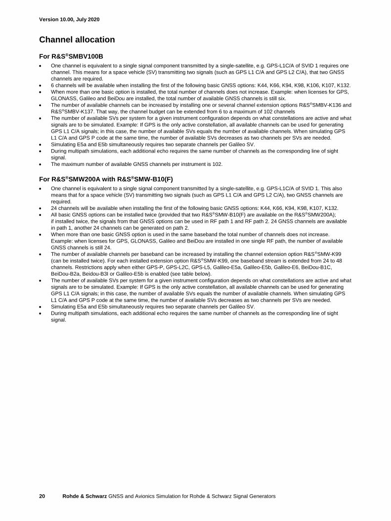
Channel allocation
For R&S®SMBV100B
• One channel is equivalent to a single signal component transmitted by a single-satellite, e.g. GPS-L1C/A of SVID 1 requires one
channel. This means for a space vehicle (SV) transmitting two signals (such as GPS L1 C/A and GPS L2 C/A), that two GNSS
channels are required.
• 6 channels will be available when installing the first of the following basic GNSS options: K44, K66, K94, K98, K106, K107, K132.
• When more than one basic option is installed, the total number of channels does not increase. Example: when licenses for GPS,
GLONASS, Galileo and BeiDou are installed, the total number of available GNSS channels is still six.
• The number of available channels can be increased by installing one or several channel extension options R&S®SMBV-K136 and
R&S®SMBV-K137. That way, the channel budget can be extended from 6 to a maximum of 102 channels
• The number of available SVs per system for a given instrument configuration depends on what constellations are active and what
signals are to be simulated. Example: If GPS is the only active constellation, all available channels can be used for generating
GPS L1 C/A signals; in this case, the number of available SVs equals the number of available channels. When simulating GPS
L1 C/A and GPS P code at the same time, the number of available SVs decreases as two channels per SVs are needed.
• Simulating E5a and E5b simultaneously requires two separate channels per Galileo SV.
• During multipath simulations, each additional echo requires the same number of channels as the corresponding line of sight
signal.
• The maximum number of available GNSS channels per instrument is 102.
For R&S®SMW200A with R&S®SMW-B10(F)
• One channel is equivalent to a single signal component transmitted by a single-satellite, e.g. GPS-L1C/A of SVID 1. This also
means that for a space vehicle (SV) transmitting two signals (such as GPS L1 C/A and GPS L2 C/A), two GNSS channels are
required.
• 24 channels will be available when installing the first of the following basic GNSS options: K44, K66, K94, K98, K107, K132.
• All basic GNSS options can be installed twice (provided that two R&S®SMW-B10(F) are available on the R&S®SMW200A);
if installed twice, the signals from that GNSS options can be used in RF path 1 and RF path 2. 24 GNSS channels are available
in path 1, another 24 channels can be generated on path 2.
• When more than one basic GNSS option is used in the same baseband the total number of channels does not increase.
Example: when licenses for GPS, GLONASS, Galileo and BeiDou are installed in one single RF path, the number of available
GNSS channels is still 24.
• The number of available channels per baseband can be increased by installing the channel extension option R&S®SMW-K99
(can be installed twice). For each installed extension option R&S®SMW-K99, one baseband stream is extended from 24 to 48
channels. Restrictions apply when either GPS-P, GPS-L2C, GPS-L5, Galileo-E5a, Galileo-E5b, Galileo-E6, BeiDou-B1C,
BeiDou-B2a, Beidou-B3I or Galileo-E5b is enabled (see table below).
• The number of available SVs per system for a given instrument configuration depends on what constellations are active and what
signals are to be simulated. Example: If GPS is the only active constellation, all available channels can be used for generating
GPS L1 C/A signals; in this case, the number of available SVs equals the number of available channels. When simulating GPS
L1 C/A and GPS P code at the same time, the number of available SVs decreases as two channels per SVs are needed.
• Simulating E5a and E5b simultaneously requires two separate channels per Galileo SV.
• During multipath simulations, each additional echo requires the same number of channels as the corresponding line of sight
signal.
Version 10.00, July 2020
Rohde & Schwarz GNSS and Avionics Simulation for Rohde & Schwarz Signal Generators 21
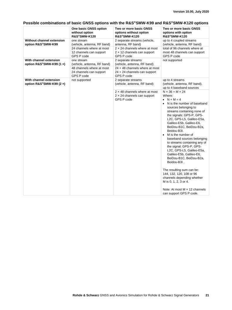
Possible combinations of basic GNSS options with the R&S®SMW-K99 and R&S®SMW-K120 options
One basic GNSS option
without option
R&S®SMW-K120
Two or more basic GNSS
options without option
R&S®SMW-K120
Two or more basic GNSS
options with option
R&S®SMW-K120
Without channel extension
option R&S®SMW-K99
one stream
(vehicle, antenna, RF band)
2 separate streams (vehicle,
antenna, RF band)
up to 4 coupled streams
(vehicle, antenna, RF band)
24 channels where at most
12 channels can support
GPS P code
2 × 24 channels where at most
2 × 12 channels can support
GPS P code
total of 96 channels where at
most 48 channels can support
GPS P code
With channel extension
option R&S®SMW-K99 (1 ×)
one stream
(vehicle, antenna, RF band)
2 separate streams
(vehicle, antenna, RF band)
not supported
48 channels where at most
24 channels can support
GPS P code
24 + 48 channels where at most
24 + 24 channels can support
GPS P code
With channel extension
option R&S®SMW-K99 (2 ×)
not supported 2 separate streams
(vehicle, antenna, RF band)
up to 4 streams
(vehicle, antenna, RF band),
up to 4 baseband sources
2 × 48 channels where at most
2 × 24 channels can support
GPS P code
N × 36 + M × 24
Where:
• N + M = 4
• N is the number of baseband
sources belonging to
streams containing none of
the signals: GPS-P, GPS-
L2C, GPS-L5, Galileo-E5a,
Galileo-E5b, Galileo-E6,
BeiDou-B1C, BeiDou-B2a,
Beidou-B3I.
• M is the number of
baseband sources belonging
to streams containing any of
the signal: GPS-P, GPS-
L2C, GPS-L5, Galileo-E5a,
Galileo-E5b, Galileo-E6,
BeiDou-B1C, BeiDou-B2a,
Beidou-B3I .
The resulting sum can be:
144, 132, 120, 108 or 96
channels depending whether
M is 0, 1, 2, 3 or 4.
Note: At most M × 12 channels
can support GPS P code.
Version 10.00, July 2020
Rohde & Schwarz GNSS and Avionics Simulation for Rohde & Schwarz Signal Generators 22
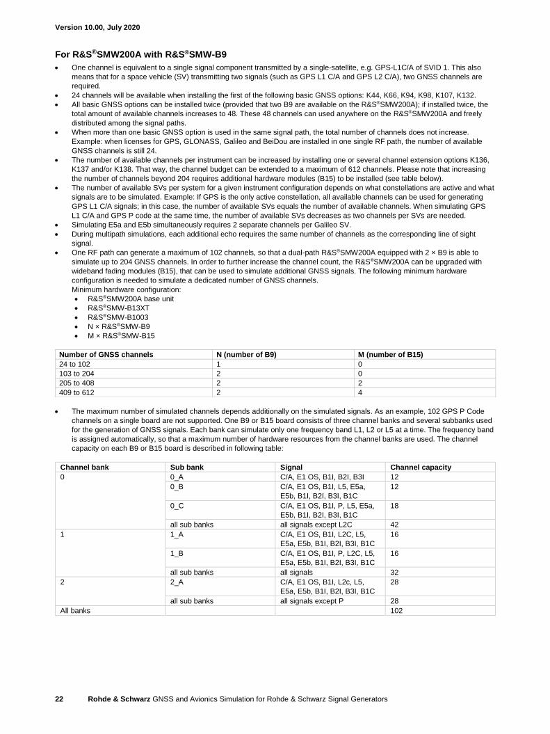
For R&S®SMW200A with R&S®SMW-B9
• One channel is equivalent to a single signal component transmitted by a single-satellite, e.g. GPS-L1C/A of SVID 1. This also
means that for a space vehicle (SV) transmitting two signals (such as GPS L1 C/A and GPS L2 C/A), two GNSS channels are
required.
• 24 channels will be available when installing the first of the following basic GNSS options: K44, K66, K94, K98, K107, K132.
• All basic GNSS options can be installed twice (provided that two B9 are available on the R&S®SMW200A); if installed twice, the
total amount of available channels increases to 48. These 48 channels can used anywhere on the R&S®SMW200A and freely
distributed among the signal paths.
• When more than one basic GNSS option is used in the same signal path, the total number of channels does not increase.
Example: when licenses for GPS, GLONASS, Galileo and BeiDou are installed in one single RF path, the number of available
GNSS channels is still 24.
• The number of available channels per instrument can be increased by installing one or several channel extension options K136,
K137 and/or K138. That way, the channel budget can be extended to a maximum of 612 channels. Please note that increasing
the number of channels beyond 204 requires additional hardware modules (B15) to be installed (see table below).
• The number of available SVs per system for a given instrument configuration depends on what constellations are active and what
signals are to be simulated. Example: If GPS is the only active constellation, all available channels can be used for generating
GPS L1 C/A signals; in this case, the number of available SVs equals the number of available channels. When simulating GPS
L1 C/A and GPS P code at the same time, the number of available SVs decreases as two channels per SVs are needed.
• Simulating E5a and E5b simultaneously requires 2 separate channels per Galileo SV.
• During multipath simulations, each additional echo requires the same number of channels as the corresponding line of sight
signal.
• One RF path can generate a maximum of 102 channels, so that a dual-path R&S®SMW200A equipped with 2 × B9 is able to
simulate up to 204 GNSS channels. In order to further increase the channel count, the R&S®SMW200A can be upgraded with
wideband fading modules (B15), that can be used to simulate additional GNSS signals. The following minimum hardware
configuration is needed to simulate a dedicated number of GNSS channels.
Minimum hardware configuration:
• R&S®SMW200A base unit
• R&S®SMW-B13XT
• R&S®SMW-B1003
• N × R&S®SMW-B9
• M × R&S®SMW-B15
Number of GNSS channels N (number of B9) M (number of B15)
24 to 102 1 0
103 to 204 2 0
205 to 408 2 2
409 to 612 2 4
• The maximum number of simulated channels depends additionally on the simulated signals. As an example, 102 GPS P Code
channels on a single board are not supported. One B9 or B15 board consists of three channel banks and several subbanks used
for the generation of GNSS signals. Each bank can simulate only one frequency band L1, L2 or L5 at a time. The frequency band
is assigned automatically, so that a maximum number of hardware resources from the channel banks are used. The channel
capacity on each B9 or B15 board is described in following table:
Channel bank Sub bank Signal Channel capacity
0 0_A C/A, E1 OS, B1I, B2I, B3I 12
0_B C/A, E1 OS, B1I, L5, E5a,
E5b, B1I, B2I, B3I, B1C
12
0_C C/A, E1 OS, B1I, P, L5, E5a,
E5b, B1I, B2I, B3I, B1C
18
all sub banks all signals except L2C 42
1 1_A C/A, E1 OS, B1I, L2C, L5,
E5a, E5b, B1I, B2I, B3I, B1C
16
1_B C/A, E1 OS, B1I, P, L2C, L5,
E5a, E5b, B1I, B2I, B3I, B1C
16
all sub banks all signals 32
2 2_A C/A, E1 OS, B1I, L2c, L5,
E5a, E5b, B1I, B2I, B3I, B1C
28
all sub banks all signals except P 28
All banks 102
Version 10.00, July 2020
Rohde & Schwarz GNSS and Avionics Simulation for Rohde & Schwarz Signal Generators 23
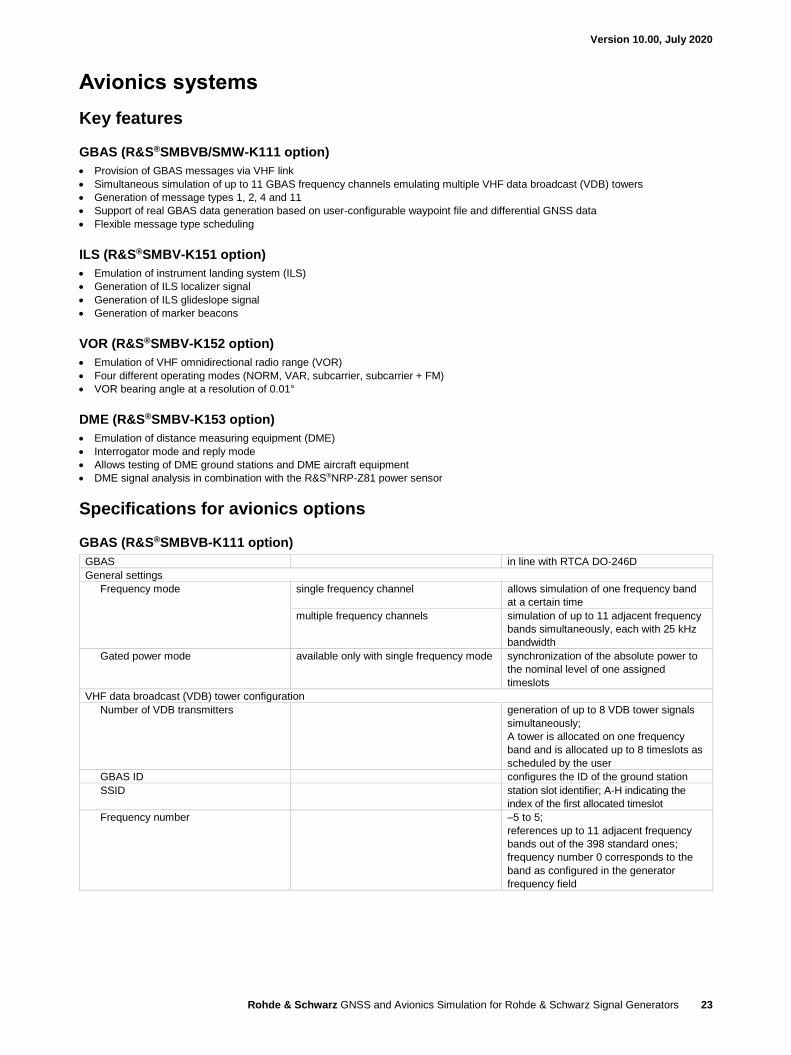
Avionics systems
Key features
GBAS (R&S®SMBVB/SMW-K111 option)
• Provision of GBAS messages via VHF link
• Simultaneous simulation of up to 11 GBAS frequency channels emulating multiple VHF data broadcast (VDB) towers
• Generation of message types 1, 2, 4 and 11
• Support of real GBAS data generation based on user-configurable waypoint file and differential GNSS data
• Flexible message type scheduling
ILS (R&S®SMBV-K151 option)
• Emulation of instrument landing system (ILS)
• Generation of ILS localizer signal
• Generation of ILS glideslope signal
• Generation of marker beacons
VOR (R&S®SMBV-K152 option)
• Emulation of VHF omnidirectional radio range (VOR)
• Four different operating modes (NORM, VAR, subcarrier, subcarrier + FM)
• VOR bearing angle at a resolution of 0.01°
DME (R&S®SMBV-K153 option)
• Emulation of distance measuring equipment (DME)
• Interrogator mode and reply mode
• Allows testing of DME ground stations and DME aircraft equipment
• DME signal analysis in combination with the R&S®NRP-Z81 power sensor
Specifications for avionics options
GBAS (R&S®SMBVB-K111 option)
GBAS in line with RTCA DO-246D
General settings
Frequency mode single frequency channel allows simulation of one frequency band
at a certain time
multiple frequency channels simulation of up to 11 adjacent frequency
bands simultaneously, each with 25 kHz
bandwidth
Gated power mode available only with single frequency mode synchronization of the absolute power to
the nominal level of one assigned
timeslots
VHF data broadcast (VDB) tower configuration
Number of VDB transmitters generation of up to 8 VDB tower signals
simultaneously;
A tower is allocated on one frequency
band and is allocated up to 8 timeslots as
scheduled by the user
GBAS ID configures the ID of the ground station
SSID station slot identifier; A-H indicating the
index of the first allocated timeslot
Frequency number –5 to 5;
references up to 11 adjacent frequency
bands out of the 398 standard ones;
frequency number 0 corresponds to the
band as configured in the generator
frequency field
Version 10.00, July 2020
Rohde & Schwarz GNSS and Avionics Simulation for Rohde & Schwarz Signal Generators 24
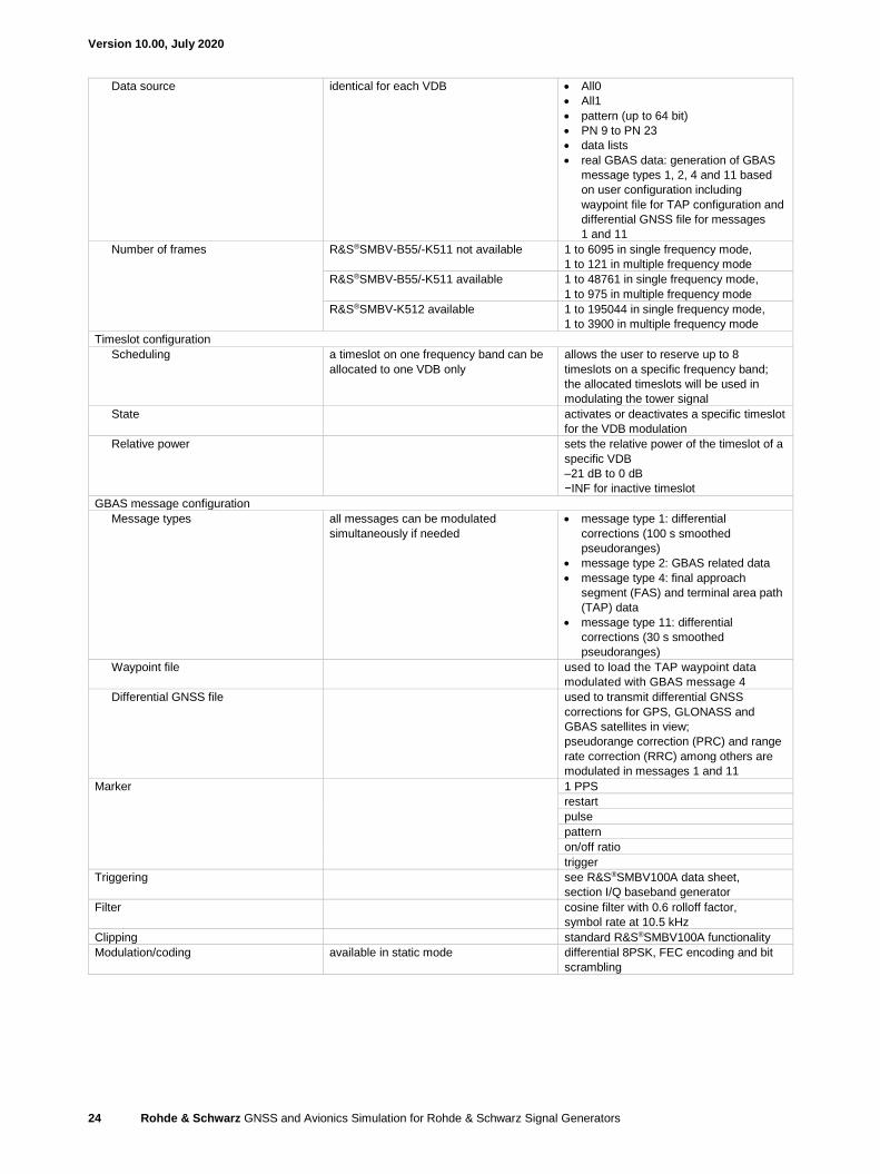
Data source identical for each VDB • All0
• All1
• pattern (up to 64 bit)
• PN 9 to PN 23
• data lists
• real GBAS data: generation of GBAS
message types 1, 2, 4 and 11 based
on user configuration including
waypoint file for TAP configuration and
differential GNSS file for messages
1 and 11
Number of frames R&S®SMBV-B55/-K511 not available 1 to 6095 in single frequency mode,
1 to 121 in multiple frequency mode
R&S®SMBV-B55/-K511 available 1 to 48761 in single frequency mode,
1 to 975 in multiple frequency mode
R&S®SMBV-K512 available 1 to 195044 in single frequency mode,
1 to 3900 in multiple frequency mode
Timeslot configuration
Scheduling a timeslot on one frequency band can be
allocated to one VDB only
allows the user to reserve up to 8
timeslots on a specific frequency band;
the allocated timeslots will be used in
modulating the tower signal
State activates or deactivates a specific timeslot
for the VDB modulation
Relative power sets the relative power of the timeslot of a
specific VDB
–21 dB to 0 dB
−INF for inactive timeslot
GBAS message configuration
Message types all messages can be modulated
simultaneously if needed
• message type 1: differential
corrections (100 s smoothed
pseudoranges)
• message type 2: GBAS related data
• message type 4: final approach
segment (FAS) and terminal area path
(TAP) data
• message type 11: differential
corrections (30 s smoothed
pseudoranges)
Waypoint file used to load the TAP waypoint data
modulated with GBAS message 4
Differential GNSS file used to transmit differential GNSS
corrections for GPS, GLONASS and
GBAS satellites in view;
pseudorange correction (PRC) and range
rate correction (RRC) among others are
modulated in messages 1 and 11
Marker 1 PPS
restart
pulse
pattern
on/off ratio
trigger
Triggering see R&S®SMBV100A data sheet,
section I/Q baseband generator
Filter cosine filter with 0.6 rolloff factor,
symbol rate at 10.5 kHz
Clipping standard R&S®SMBV100A functionality
Modulation/coding available in static mode differential 8PSK, FEC encoding and bit
scrambling
Version 10.00, July 2020
Rohde & Schwarz GNSS and Avionics Simulation for Rohde & Schwarz Signal Generators 25
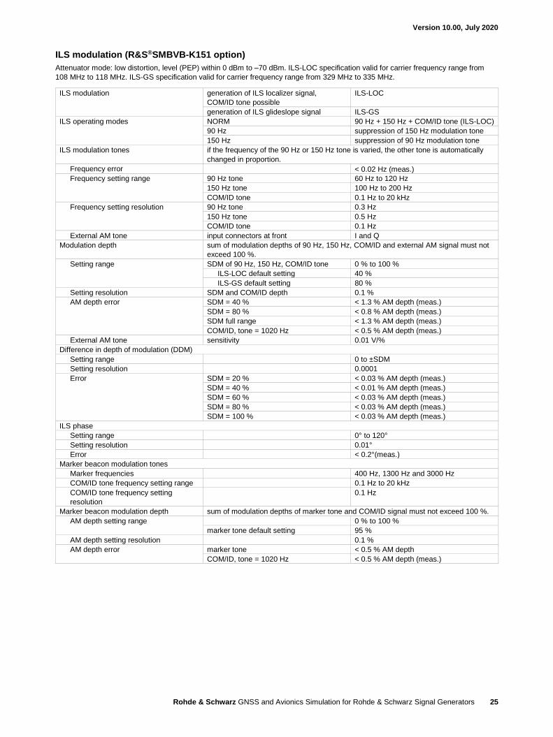
ILS modulation (R&S®SMBVB-K151 option)
Attenuator mode: low distortion, level (PEP) within 0 dBm to –70 dBm. ILS-LOC specification valid for carrier frequency range from
108 MHz to 118 MHz. ILS-GS specification valid for carrier frequency range from 329 MHz to 335 MHz.
ILS modulation generation of ILS localizer signal,
COM/ID tone possible
ILS-LOC
generation of ILS glideslope signal ILS-GS
ILS operating modes NORM 90 Hz + 150 Hz + COM/ID tone (ILS-LOC)
90 Hz suppression of 150 Hz modulation tone
150 Hz suppression of 90 Hz modulation tone
ILS modulation tones if the frequency of the 90 Hz or 150 Hz tone is varied, the other tone is automatically
changed in proportion.
Frequency error < 0.02 Hz (meas.)
Frequency setting range 90 Hz tone 60 Hz to 120 Hz
150 Hz tone 100 Hz to 200 Hz
COM/ID tone 0.1 Hz to 20 kHz
Frequency setting resolution 90 Hz tone 0.3 Hz
150 Hz tone 0.5 Hz
COM/ID tone 0.1 Hz
External AM tone input connectors at front I and Q
Modulation depth sum of modulation depths of 90 Hz, 150 Hz, COM/ID and external AM signal must not
exceed 100 %.
Setting range SDM of 90 Hz, 150 Hz, COM/ID tone 0 % to 100 %
ILS-LOC default setting 40 %
ILS-GS default setting 80 %
Setting resolution SDM and COM/ID depth 0.1 %
AM depth error SDM = 40 % < 1.3 % AM depth (meas.)
SDM = 80 % < 0.8 % AM depth (meas.)
SDM full range < 1.3 % AM depth (meas.)
COM/ID, tone = 1020 Hz < 0.5 % AM depth (meas.)
External AM tone sensitivity 0.01 V/%
Difference in depth of modulation (DDM)
Setting range 0 to ±SDM
Setting resolution 0.0001
Error SDM = 20 % < 0.03 % AM depth (meas.)
SDM = 40 % < 0.01 % AM depth (meas.)
SDM = 60 % < 0.03 % AM depth (meas.)
SDM = 80 % < 0.03 % AM depth (meas.)
SDM = 100 % < 0.03 % AM depth (meas.)
ILS phase
Setting range 0° to 120°
Setting resolution 0.01°
Error < 0.2°(meas.)
Marker beacon modulation tones
Marker frequencies 400 Hz, 1300 Hz and 3000 Hz
COM/ID tone frequency setting range 0.1 Hz to 20 kHz
COM/ID tone frequency setting
resolution
0.1 Hz
Marker beacon modulation depth sum of modulation depths of marker tone and COM/ID signal must not exceed 100 %.
AM depth setting range 0 % to 100 %
marker tone default setting 95 %
AM depth setting resolution 0.1 %
AM depth error marker tone < 0.5 % AM depth
COM/ID, tone = 1020 Hz < 0.5 % AM depth (meas.)
Version 10.00, July 2020
Rohde & Schwarz GNSS and Avionics Simulation for Rohde & Schwarz Signal Generators 26
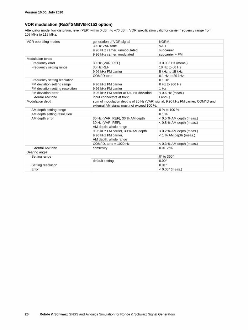
VOR modulation (R&S®SMBVB-K152 option)
Attenuator mode: low distortion, level (PEP) within 0 dBm to –70 dBm. VOR specification valid for carrier frequency range from
108 MHz to 118 MHz.
VOR operating modes generation of VOR signal NORM
30 Hz VAR tone VAR
9.96 kHz carrier, unmodulated subcarrier
9.96 kHz carrier, modulated subcarrier + FM
Modulation tones
Frequency error 30 Hz (VAR, REF) < 0.003 Hz (meas.)
Frequency setting range 30 Hz REF 10 Hz to 60 Hz
9.96 kHz FM carrier 5 kHz to 15 kHz
COM/ID tone 0.1 Hz to 20 kHz
Frequency setting resolution 0.1 Hz
FM deviation setting range 9.96 kHz FM carrier 0 Hz to 960 Hz
FM deviation setting resolution 9.96 kHz FM carrier 1 Hz
FM deviation error 9.96 kHz FM carrier at 480 Hz deviation < 0.5 Hz (meas.)
External AM tone input connectors at front I and Q
Modulation depth sum of modulation depths of 30 Hz (VAR) signal, 9.96 kHz FM carrier, COM/ID and
external AM signal must not exceed 100 %.
AM depth setting range 0 % to 100 %
AM depth setting resolution 0.1 %
AM depth error 30 Hz (VAR, REF), 30 % AM depth < 0.5 % AM depth (meas.)
30 Hz (VAR, REF),
AM depth: whole range
< 0.8 % AM depth (meas.)
9.96 kHz FM carrier, 30 % AM depth < 0.2 % AM depth (meas.)
9.96 kHz FM carrier,
AM depth: whole range
< 1 % AM depth (meas.)
COM/ID, tone = 1020 Hz < 0.3 % AM depth (meas.)
External AM tone sensitivity 0.01 V/%
Bearing angle
Setting range 0° to 360°
default setting 0.00°
Setting resolution 0.01°
Error < 0.05° (meas.)
Version 10.00, July 2020
Rohde & Schwarz GNSS and Avionics Simulation for Rohde & Schwarz Signal Generators 27
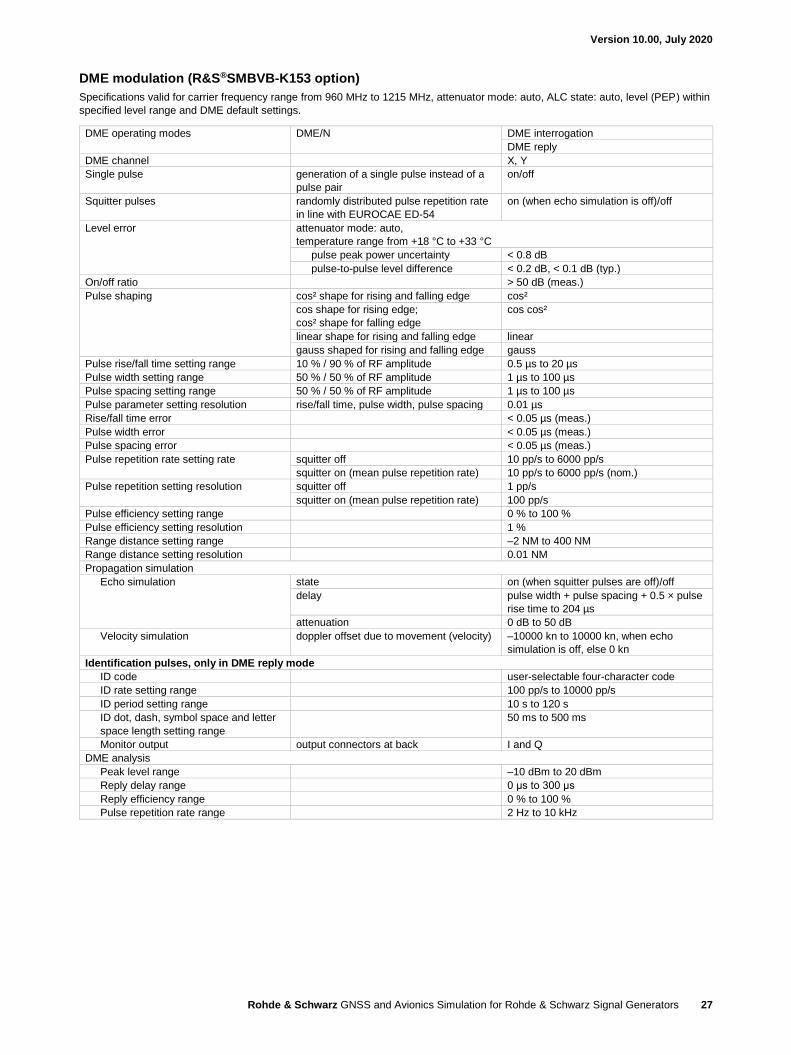
DME modulation (R&S®SMBVB-K153 option)
Specifications valid for carrier frequency range from 960 MHz to 1215 MHz, attenuator mode: auto, ALC state: auto, level (PEP) within
specified level range and DME default settings.
DME operating modes DME/N DME interrogation
DME reply
DME channel X, Y
Single pulse generation of a single pulse instead of a
pulse pair
on/off
Squitter pulses randomly distributed pulse repetition rate
in line with EUROCAE ED-54
on (when echo simulation is off)/off
Level error attenuator mode: auto,
temperature range from +18 °C to +33 °C
pulse peak power uncertainty < 0.8 dB
pulse-to-pulse level difference < 0.2 dB, < 0.1 dB (typ.)
On/off ratio > 50 dB (meas.)
Pulse shaping cos² shape for rising and falling edge cos²
cos shape for rising edge;
cos² shape for falling edge
cos cos²
linear shape for rising and falling edge linear
gauss shaped for rising and falling edge gauss
Pulse rise/fall time setting range 10 % / 90 % of RF amplitude 0.5 µs to 20 µs
Pulse width setting range 50 % / 50 % of RF amplitude 1 µs to 100 µs
Pulse spacing setting range 50 % / 50 % of RF amplitude 1 µs to 100 µs
Pulse parameter setting resolution rise/fall time, pulse width, pulse spacing 0.01 µs
Rise/fall time error < 0.05 µs (meas.)
Pulse width error < 0.05 µs (meas.)
Pulse spacing error < 0.05 µs (meas.)
Pulse repetition rate setting rate squitter off 10 pp/s to 6000 pp/s
squitter on (mean pulse repetition rate) 10 pp/s to 6000 pp/s (nom.)
Pulse repetition setting resolution squitter off 1 pp/s
squitter on (mean pulse repetition rate) 100 pp/s
Pulse efficiency setting range 0 % to 100 %
Pulse efficiency setting resolution 1 %
Range distance setting range –2 NM to 400 NM
Range distance setting resolution 0.01 NM
Propagation simulation
Echo simulation state on (when squitter pulses are off)/off
delay pulse width + pulse spacing + 0.5 × pulse
rise time to 204 µs
attenuation 0 dB to 50 dB
Velocity simulation doppler offset due to movement (velocity) –10000 kn to 10000 kn, when echo
simulation is off, else 0 kn
Identification pulses, only in DME reply mode
ID code user-selectable four-character code
ID rate setting range 100 pp/s to 10000 pp/s
ID period setting range 10 s to 120 s
ID dot, dash, symbol space and letter
space length setting range
50 ms to 500 ms
Monitor output output connectors at back I and Q
DME analysis
Peak level range –10 dBm to 20 dBm
Reply delay range 0 μs to 300 μs
Reply efficiency range 0 % to 100 %
Pulse repetition rate range 2 Hz to 10 kHz
Version 10.00, July 2020
Rohde & Schwarz GNSS and Avionics Simulation for Rohde & Schwarz Signal Generators 28
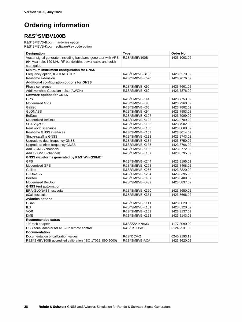
Ordering information
R&S®SMBV100B
R&S®SMBVB-Bxxx = hardware option
R&S®SMBVB-Kxxx = software/key code option
Designation Type Order No.
Vector signal generator, including baseband generator with ARB
(64 Msample, 120 MHz RF bandwidth), power cable and quick
start guide
R&S®SMBV100B 1423.1003.02
Minimum instrument configuration for GNSS
Frequency option, 8 kHz to 3 GHz R&S®SMBVB-B103 1423.6270.02
Real-time extension R&S®SMBVB-K520 1423.7676.02
Additional configuration options for GNSS
Phase coherence R&S®SMBVB-K90 1423.7601.02
Additive white Gaussian noise (AWGN) R&S®SMBVB-K62 1423.7876.02
Software options for GNSS
GPS R&S®SMBVB-K44 1423.7753.02
Modernized GPS R&S®SMBVB-K98 1423.7960.02
Galileo R&S®SMBVB-K66 1423.7882.02
GLONASS R&S®SMBVB-K94 1423.7953.02
BeiDou R&S®SMBVB-K107 1423.7999.02
Modernized BeiDou R&S®SMBVB-K132 1423.8789.02
SBAS/QZSS R&S®SMBVB-K106 1423.7982.02
Real world scenarios R&S®SMBVB-K108 1423.8008.02
Real-time GNSS interfaces R&S®SMBVB-K109 1423.8014.02
Single-satellite GNSS R&S®SMBVB-K133 1423.8743.02
Upgrade to dual-frequency GNSS R&S®SMBVB-K134 1423.8750.02
Upgrade to triple-frequency GNSS R&S®SMBVB-K135 1423.8766.02
Add 6 GNSS channels R&S®SMBVB-K136 1423.8772.02
Add 12 GNSS channels R&S®SMBVB-K137 1423.8795.02
GNSS waveforms generated by R&S®WinIQSIM2™
GPS R&S®SMBVB-K244 1423.8195.02
Modernized GPS R&S®SMBVB-K298 1423.8408.02
Galileo R&S®SMBVB-K266 1423.8320.02
GLONASS R&S®SMBVB-K294 1423.8395.02
BeiDou R&S®SMBVB-K407 1423.8489.02
Modernized BeiDou R&S®SMBVB-K432 1423.8837.02
GNSS test automation
ERA-GLONASS test suite R&S®SMBVB-K360 1423.8650.02
eCall test suite R&S®SMBVB-K361 1423.8666.02
Avionics options
GBAS R&S®SMBVB-K111 1423.8020.02
ILS R&S®SMBVB-K151 1423.8120.02
VOR R&S®SMBVB-K152 1423.8137.02
DME R&S®SMBVB-K153 1423.8143.02
Recommended extras
19" rack adapter R&S®ZZA-KNA33 1177.8090.00
USB serial adapter for RS-232 remote control R&S®TS-USB1 6124.2531.00
Documentation
Documentation of calibration values R&S®DCV-2 0240.2193.18
R&S®SMBV100B accredited calibration (ISO 17025, ISO 9000) R&S®SMBVB-ACA 1423.8620.02
Version 10.00, July 2020
Rohde & Schwarz GNSS and Avionics Simulation for Rohde & Schwarz Signal Generators 29
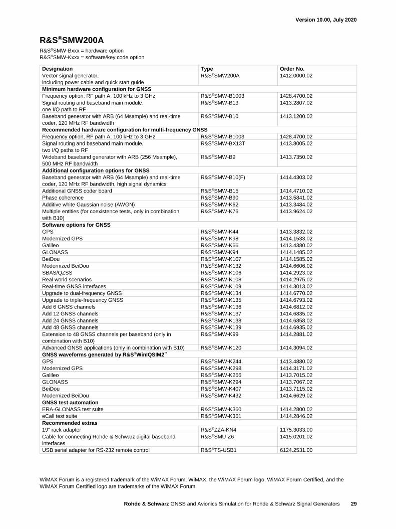
R&S®SMW200A
R&S®SMW-Bxxx = hardware option
R&S®SMW-Kxxx = software/key code option
Designation Type Order No.
Vector signal generator,
including power cable and quick start guide
R&S®SMW200A 1412.0000.02
Minimum hardware configuration for GNSS
Frequency option, RF path A, 100 kHz to 3 GHz R&S®SMW-B1003 1428.4700.02
Signal routing and baseband main module,
one I/Q path to RF
R&S®SMW-B13 1413.2807.02
Baseband generator with ARB (64 Msample) and real-time
coder, 120 MHz RF bandwidth
R&S®SMW-B10 1413.1200.02
Recommended hardware configuration for multi-frequency GNSS
Frequency option, RF path A, 100 kHz to 3 GHz R&S®SMW-B1003 1428.4700.02
Signal routing and baseband main module,
two I/Q paths to RF
R&S®SMW-BX13T 1413.8005.02
Wideband baseband generator with ARB (256 Msample),
500 MHz RF bandwidth
R&S®SMW-B9 1413.7350.02
Additional configuration options for GNSS
Baseband generator with ARB (64 Msample) and real-time
coder, 120 MHz RF bandwidth, high signal dynamics
R&S®SMW-B10(F) 1414.4303.02
Additional GNSS coder board R&S®SMW-B15 1414.4710.02
Phase coherence R&S®SMW-B90 1413.5841.02
Additive white Gaussian noise (AWGN) R&S®SMW-K62 1413.3484.02
Multiple entities (for coexistence tests, only in combination
with B10)
R&S®SMW-K76 1413.9624.02
Software options for GNSS
GPS R&S®SMW-K44 1413.3832.02
Modernized GPS R&S®SMW-K98 1414.1533.02
Galileo R&S®SMW-K66 1413.4380.02
GLONASS R&S®SMW-K94 1414.1485.02
BeiDou R&S®SMW-K107 1414.1585.02
Modernized BeiDou R&S®SMW-K132 1414.6606.02
SBAS/QZSS R&S®SMW-K106 1414.2923.02
Real world scenarios R&S®SMW-K108 1414.2975.02
Real-time GNSS interfaces R&S®SMW-K109 1414.3013.02
Upgrade to dual-frequency GNSS R&S®SMW-K134 1414.6770.02
Upgrade to triple-frequency GNSS R&S®SMW-K135 1414.6793.02
Add 6 GNSS channels R&S®SMW-K136 1414.6812.02
Add 12 GNSS channels R&S®SMW-K137 1414.6835.02
Add 24 GNSS channels R&S®SMW-K138 1414.6858.02
Add 48 GNSS channels R&S®SMW-K139 1414.6935.02
Extension to 48 GNSS channels per baseband (only in
combination with B10)
R&S®SMW-K99 1414.2881.02
Advanced GNSS applications (only in combination with B10) R&S®SMW-K120 1414.3094.02
GNSS waveforms generated by R&S®WinIQSIM2™
GPS R&S®SMW-K244 1413.4880.02
Modernized GPS R&S®SMW-K298 1414.3171.02
Galileo R&S®SMW-K266 1413.7015.02
GLONASS R&S®SMW-K294 1413.7067.02
BeiDou R&S®SMW-K407 1413.7115.02
Modernized BeiDou R&S®SMW-K432 1414.6629.02
GNSS test automation
ERA-GLONASS test suite R&S®SMW-K360 1414.2800.02
eCall test suite R&S®SMW-K361 1414.2846.02
Recommended extras
19" rack adapter R&S®ZZA-KN4 1175.3033.00
Cable for connecting Rohde & Schwarz digital baseband
interfaces
R&S®SMU-Z6 1415.0201.02
USB serial adapter for RS-232 remote control R&S®TS-USB1 6124.2531.00
WiMAX Forum is a registered trademark of the WiMAX Forum. WiMAX, the WiMAX Forum logo, WiMAX Forum Certified, and the
WiMAX Forum Certified logo are trademarks of the WiMAX Forum.

Version 10.00, July 2020
Rohde & Schwarz GNSS and Avionics Simulation for Rohde & Schwarz Signal Generators 30

Version 10.00, July 2020
Rohde & Schwarz GNSS and Avionics Simulation for Rohde & Schwarz Signal Generators 31
Service that adds value► Worldwide► Local und personalized► Customized and flexible► Uncompromising quality► Long-term dependability
3607
.689
6.22
10.
00 P
DP
1 e
n
R&S® is a registered trademark of Rohde & Schwarz GmbH & Co. KG Trade names are trademarks of the owners PD 3607.6896.22 | Version 10.00 | July 2020 (ja) GNSS and Avionics Simulation for Rohde & Schwarz Signal Generators Data without tolerance limits is not binding | Subject to change © 2017 - 2020 Rohde & Schwarz GmbH & Co. KG | 81671 Munich, Germany
Sustainable product design ► Environmental compatibility and eco-footprint ► Energy efficiency and low emissions ► Longevity and optimized total cost of ownership
Certified Quality Management
ISO 9001
Rohde & Schwarz customer supportwww.rohde-schwarz.com/support
Rohde & SchwarzThe Rohde & Schwarz electronics group offers innovative solutions in the following business fields: test and mea-surement, broadcast and media, secure communications, cybersecurity, monitoring and network testing. Founded more than 80 years ago, the independent company which is headquartered in Munich, Germany, has an extensive sales and service network with locations in more than 70 countries.
www.rohde-schwarz.com
Rohde & Schwarz trainingwww.training.rohde-schwarz.com
Certified Environmental Management
ISO 14001
3607689622