Embed Size (px)
Citation preview
Publication: MAN1014C Revision Date: 09/01/08
MAC EQUIPMENT, INC. P.O. BOX 205
SABETHA, KS 66534
SALES, PARTS & SERVICE: 1-888-821-2476 www.macequipment.com
RAM AIRLOCK
INSTALLATION, OPERATION
& MAINTENANCE MANUAL


Publication: MAN1014C MAC Equipment Inc. 1
TABLE OF CONTENTS
DESCRIPTION PAGE
General Introduction.............................................................. 2
Safety ................................................................................... 2
Principle of Operation............................................................ 5
Installation............................................................................. 6
Initial Start-Up Procedure...................................................... 10
Maintenance .................................................................... 11
Troubleshooting .................................................................... 13
Spare Parts........................................................................... 15
LIST OF FIGURES Page Figure 1-1 Proper Handling of the Airlock .............................2
Figure 1-2 Typical RAM Airlock.............................................2
Figure 2-1 Lockout and Tagout of
Electrical Service and Compressed Air.................3
Figure 2-2 Shear Hazard.......................................................3
Figure 2-3 Shear Hazard Points............................................3
Figure 2-4 Chain Drive Hazard..............................................3
Figure 2-5 Open Inlet and Outlet Throats..............................4
Figure 2-6 Typical Location of Safety Decals ........................4
Figure 3-1 Principle of Operation ..........................................5
Figure 3-2 Open End and Closed End Rotors .......................6
Figure 4-1 Connecting the Airlock
to Feed and Discharge Devices...........................6
Figure 4-2 Typical Discharge Guard .....................................6
Figure 4-3 Shear Protector....................................................7
Figure 4-4 Vented Shear Protector .......................................7
Figure 4-5 Maintenance Gate ...............................................8
Figure 4-6 Adjusting the Motion Switch.................................8
Figure 4-7 Typical Air Purge System.....................................9
Figure 4-8 Typical Discharge Guard .....................................9
Figure 4-9 Blow-thru Adapter and Surge Hopper ..................9
Figure 4-10 Installation of the Blow-thru
Adapter and Surge Hopper ...............................10
Figure 6-1 Checking Rotor Clearances ...............................11
Figure 6-2 Adjustable Rotor Tips ........................................11
Figure 6-3 Removing the Rotor...........................................11
Figure 6-4 Replacing Bearings and Seals ...........................12
Figure 6-5 Adjusting the Drive Chain ..................................12
It is the owner's responsibility to maintain the safety features included with this equipment. The safety features may include, but not necessarily be limited to: guards, access doors and covers, explosion vents, warning decals, caution decals, and advisory decals. Replacement safety features are available from MAC Equipment, Inc.
DO NOT attempt to operate this equipment until you have read and understood the contents of this manual. If you do not understand the contents of the manual bring it to the attention of your supervisor. This manual contains important safety instructions concerning the maintenance, use, and operation of this product. Failure to follow these instructions may result in serious injury or death.
NO haga funcionar este equipo hasta haber leido y comprehendido el contenido de este manual. Si aiguna partre del contenido del manual queda sin comprehender, notifiqueselo a su supervisor. Este manual contiene instrucciones importantes en cuanto al anterimiento, uso, y funcionamiento sequros de este producto. El no seguir las instrucciones contenidas en este manual podria ocasionar lesiones graves.

Publication: MAN1014C MAC Equipment Inc. 2
GENERAL INTRODUCTION Congratulations on your selection of a MAC RAM Airlock. As the owner/operator of this unit you have an important responsibility to see that it is operated and maintained in a safe manner. The unit will require very little attention to keep it in good operating condition. This manual has been prepared to aid you in that effort.
RECEIVING YOUR EQUIPMENT
As soon as the equipment is received, it should be carefully inspected to make certain the unit is in good condition and all items listed on the packing list are received. Even though the equipment is mounted on heavy shipping skids at our plant it is possible for it to be damaged in shipment. All damage or shortages should be noted on the Bill of Lading. The purchaser must take immediate steps to file reports and damage claims with the carrier. All damages incurred to the unit in transit are the responsibility of the common carrier since it is the policy of MAC Equipment, Inc. to make shipment F.O.B. from its factory. Ownership passes to purchaser when the unit is loaded and accepted by carrier. Any claims for in transit damage or shortage must be brought against the carrier by the purchaser.
Handling and Storage of your Equipment
If the unit is not going to be assembled and installed soon after arrival, it should be stored in a warm, dry location to protect against rust and corrosion.
The airlock is shipped from our factory mounted on a heavy shipping skid and generally has an inlet throat cover to prevent foreign materials from entering the airlock during shipping. It is recommended that the airlock remain bolted to the skid with the throat cover in place until just prior to installation.
Transport the airlock from the unloading site to the installation or storage site by using a forklift or hand-truck to pick it up by the skid. Do not lift the airlock by it�s flanges.
THIS! NOT THIS!
Figure 1-1 Proper Handling of the Airlock
Getting to Know Your Airlock
Throughout this manual, reference may be made to various components which may or may not be part of your particular system. They are included in the interest of fully describing typical MD Airlocks.
Figure 1-2 Typical RAM Airlock
Terms and Definitions
Throughout this manual you will see several terms that apply to your airlock. The following terms and definitions may be helpful:
RAM RAM is an airlock model designation. This model incorporates TS-4 shaft seals at each endplate.
C.F.R. Cubic Feet per Revolution, or the displaced volume of material that the airlock would move from the inlet throat to the outlet throat during one complete (360°)
revolution of the rotor.
C.F.R. is calculated assuming that the rotor pockets are 100% filled; actual C.F.R. may vary due to pocket fill efficiency and rotor speed.
RAM10 The number after the model designation indicates the Inlet & Outlet flange size. Thus RAM08 airlock has a 8� 150# flange pattern. The table shows the C.F.R. ratings of available airlock models.
Airlock C.F.R. Ratings
Approximate Cubic Feet Per Revolution C.F.R.
Model
OE Rotor CE Rotor
Typical Horsepower
Range
RAM06 .19 .17 3/4
RAM08 .36 .32 3/4
RAM10 .70 64 1
RAM12 1.47 1.36 1 1/2
RAM14 2.39 2.25 3
RAM16 3.11 2.90 3
Temperature Ratings The standard temperature rating for RAM airlocks is 200 F. Special high-temperature airlocks rated 200 to 450 are available on special order. Refer to the Order Acknowledgment for the temperature rating of your airlock.
SAFETY INFORMATION
WARNING !
Recognize Safety Information
Understand Signal Words DANGER ! Indicates an imminently hazardous situation which, if not avoided, will result in death or serious injury.
WARNING!
Indicates a potentially hazardous situation which, if not avoided, could result in death or serious injury.
CAUTION!
Indicates a potentially hazardous situation which, if not avoided, may result in minor or moderate injury and/or property damage.
Warning decals and guards
This piece of equipment contains several warning decals located in many different locations. It is the owner/operator�s responsibility to maintain the integrity of these decals and to ensure that all
operators of the equipment are aware of them and understand their meaning. Replacement decals are available free of charge from your MAC Equipment Service Representative, or by calling MAC Equipment Inc. at 1-888-821-2476.
This piece of equipment may contain one or more safety guards to protect the operator(s) from injury. It is the owner/operator�s responsibility to maintain the integrity of these guards and
ensure that they are in place when the equipment is in operation.
Lockout-Tagout Requirements
The symbol at left is used to alert you to important safety messages located throughout this manual. It also appears on the equipment to alert you to potential hazards. When you see this symbol you must read, understand, and heed the information that accompanies it.
Do not attempt to operate or maintain this piece of equipment until you have read and thoroughly understood all of the safety information contained in this manual. All such information must be taken seriously. This piece of equipment contains moving parts and potential pinch points which can cause serious injury or death. If you do not understand anything in this manual seek assistance from your supervisor before operating this equipment.
Before inspecting or servicing this equipment perform an approved lockout-tagout procedure on the electrical service, the compressed air (or other gas) supply, or any other energy source.
DO NOT attempt to operate this equipment with any guard removed. Replace damaged guards.

Publication: MAN1014C MAC Equipment Inc. 3
ELECTRICAL POWER COMPRESSED AIR OR GAS
Figure 2-1 Lockout and Tagout of Electrical Service and Compressed Air (or other gas)
Control of this equipment must be in accordance with OSHA Standard 1910.147 "The control of hazardous energy (lockout-tagout)". This standard "requires employers to establish a program and utilize procedures for affixing appropriate lockout devices or tagout devices to energy isolating devices and to otherwise disable machines or equipment to prevent unexpected energizing, start-up or release of stored energy in order to prevent injury to employees".
For further information on Lockout-Tagout requirements, see your company's Safety Director or refer to OSHA Standard 1910.147.
Hazard Review & Safety Instructions The most common airlock hazards and their potential injuries are described below. Although this is not an exhaustive list, it does cover those hazards which are most likely to be encountered.
Shear Hazard
Figure 2-2 Shear Hazard
Figure 2-3 Shear Hazard Points 1. Shear Point 4. Rotor 2. Inlet Throat 5. Access Door 3. Outlet Throat 6. Discharge Guard Eliminate or avoid amputation and shear hazards by: 1. Performing Lockout/Tagout before inspecting, cleaning or servicing the airlock 2. Never reaching into an airlock that is not locked out. 3. Guarding or interlocking access doors or ports with reach-in access to the rotor. 4. Blocking the rotor from turning if the drive chain is disconnected.
Drive Chain Hazard
Another shear/pinch hazard point exists when a chain or belt drive is exposed. Typically, operators are at greatest risk of a drive chain accident when the guard is removed and they are performing maintenance on the drive components. This shear/pinch hazard does not exist when all appropriate guards are in place. Warning labels must be on and behind the drive guard to remind operators of this hazard.
Figure 2-4 Chain Drive Hazard 1. Shear/Pinch Point 2. Warning label behind guard Eliminate or avoid this hazard by: 1. Never operating the airlock with the guard removed. 2. Performing Lockout/Tagout before removing the guard.
Entanglement Hazard
An entanglement hazard exists where rotating shafts are exposed. Exposed locations can include the tail shaft and seal access points. The tail shaft is typically guarded if the exposed shaft extends more than 1 inch beyond the endplate. Eliminate or avoid this hazard by: 1. Never operating the airlock with tail shaft guard removed. 2. Not touching a rotating shaft. 3. Not wearing loose clothing or jewelry and keeping hair tied up. 4. Guarding an exposed extended tail shaft.
Electrocution Hazard
Electrocution accidents are most likely to occur during maintenance of the electrical system or when working on or near exposed high voltage wiring. This hazard does not exist when the electrical power has been disconnected, properly locked and tagged out.
Eliminate or avoid this hazard by: 1. Performing Lockout/Tagout before inspecting or servicing electrical devices.
Cut Hazard
Eliminate or avoid this hazard by:
1. Do not slide fingers, hands or other body parts against sharp edges.
Airlocks contain parts that are sharp and therefore can cut fingers, hands or other body parts.
Airlocks contain moving parts that will catch objects and shear them off. Contact with moving rotor blades will amputate fingers, hands, arms or legs and may result in death.
Shear hazards are very serious. The shear hazard points are located wherever a rotor and housing meet. Safety guarding to prevent injury is normally not possible since the guard would block the flow of material through the airlock, thus preventing the airlock from performing its primary function. Warning labels must be located on the airlock and adjacent access ports to remind personnel of this hazard.
Shear accidents can also occur when operators reach into upstream or downstream equipment such as hoppers or chutes through access doors, discharge chutes or similar openings, inadvertently contacting a moving rotor. Operators are most prone to make this mistake when attempting to dislodge material from areas immediately above or below the airlock.
Moving drive parts can cut and crush. Contact with moving drive components will amputate or crush fingers, hands or arms.
Shown with Guard Removed For Clarity. Do Not Operate with Guard Removed.
Airlocks contain rotating shafts that may catch objects and crush or tear them off. Contact with a rotating shaft may mangle or amputate fingers, hands or arms.
Severe burns or death may result from contact with exposed high voltage sources.

Publication: MAN1014C MAC Equipment Inc. 4
Automatic Start Hazard
Airlocks are usually controlled by an automated system and may start without warning. However, automatic startup by itself is not a hazard. Failure to properly disconnect, lockout and tagout all energy sources while inspecting, servicing or attempting to dislodge material creates a very hazardous situation. Serious personal injury may result. Eliminate or avoid this hazard by: 1. Performing Lockout/Tagout before inspecting, cleaning or servicing the airlock.
Compressed Air Hazard
Puncture injuries may occur when flying debris is propelled by the uncontrolled release of compressed air. This can occur when compressed air lines are disconnected or severed.
Eliminate or avoid this hazard by: 1. Performing Lockout/Tagout and slowly bleeding off compressed air before inspecting or
servicing pressurized devices. 2. Wearing safety glasses.
Lifting Hazard
Eliminate or avoid this hazard by: 1. Using proper lifting techniques when lifting airlocks or disassembled parts. 2. Using appropriate equipment and tie off techniques for all parts that are unsafe to lift
manually. 3. Consulting the plant safety director for safe lifting limits.
Safety Precautions
Figure 2-5 Open Inlet and Outlet Throats
The airlock will be operated only by properly qualified, properly trained personnel who
have read and fully understand this manual.
Guards, access doors, and covers are in place and secure.
The equipment has been wired and grounded in accordance with all applicable codes.
The characteristics of the material being processed are known, and appropriate safety measures have been taken to protect personnel and property. Possible hazards include (but are not necessarily limited to): toxicity, high temperatures, explosive potential, chemical hazard, abrasion hazard, etc. Refer to applicable Material Safety Data Sheets (MSDS�s) or consult your supplier for the properties of the material being processed.
An approved lockout-tagout procedure has been followed before the equipment is inspected, disassembled, and/or serviced. The equipment is automatically controlled and may start without warning unless energy supplies are properly disconnected and locked out-tagged out.
The inlet and outlet throats are made inaccessible. An open inlet or outlet throat exposes the rotor blades. These blades will catch loose clothing, jewelry, long hair, etc. Anything entering the rotating blades of the airlock will be sheared off. Never reach into the inlet or outlet throat while the airlock is in operation; the probability of severe injury to fingers and hand is very high.
If an airlock is to be a point where product is added to the system, or is to discharge product into an open container, always protect the inlet throat with a guard.
Inlet and outlet guards are available from MAC Equipment, Inc.
Never reach around the airlock�s rotor shaft or drive components unless the equipment is
properly locked out and tagged out. Moving components can catch loose clothing, long hair, jewelry, etc.
Do not cut, weld or grind on or near the airlock while it is in operation; dust laden air may be highly explosive. Refer to the proper National Fire Protection Association Manual for information on cutting, welding or grinding in hazardous areas.
The work area is clean and orderly, free of debris, materials, tools, etc.
Operating personnel are wearing proper ear and eye protection and have secured loose hair, clothing, jewelry, etc
Read and Understand Safety Decals
Several safety labels are located on this piece of equipment to warn the operator(s) of potentially hazardous situations.
Decal Locations The following figure shows typical locations for safety decals on an airlock. The locations of decals for your particular airlock may vary from those indicated. Inspect your airlock for locations of all decals.
Figure 2-6 Typical Locations of Safety Decals (below is a description of decals)
Flying debris propelled by escaping compressed air may puncture skin or eyes.
Airlocks and their disassembled parts are heavy. Lifting heavy objects can cause muscle strain or severe back injury.
A.
Airlocks contain moving parts that will catch objects and shear them off. Contact with moving rotor blades will cause serious personal injury and/or property damage!
Do not operate, inspect, or service this equipment unless all the following safety precautions are in effect:
Failure to follow these instructions may result in death, personal injury, and/or property damage!
This indicates the direction that the rotor must rotate. If the unit is rotating the wrong direction, possible damage to the unit may result.
This airlock may start without warning causing serious injury. STAY CLEAR.
Publication: MAN1014C MAC Equipment Inc. 5
The following ISO decals may appear on your airlock:
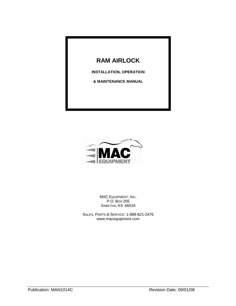
PRINCIPLE OF OPERATION The airlock is a device which transfers a granular or powdered material into or out of a pressurized system. It allows transfer of the product without loss of pressure to the atmosphere. The airlock can maintain either positive or negative pressures.
The airlock functions in a manner similar to a revolving door in a building - particles move across the pressure barrier, but airflow is blocked. The basic principle of operation is shown in Figure 3-1 below.
1
3
2
4
4
5 5
66
788
7
Non-Vented Vented
A
B
9
Figure 3-1 Principle of Operation
1. Each rotor pocket is filled with product (from a hopper, filter, sifter, or other feeding device) at the high point of its rotation.
2. Each pocket empties into downstream equipment (such as tote bin or conveyor) at the low point of its rotation.
3. Some air is returned to the material inlet as the empty pockets rotate upwards. This amount of air (blow-by) assists in maintaining a continuous flow of product into the inlet. In some applications this air can hinder product flow; if so it can be vented to the atmosphere or into a dust collector, using optional equipment.
The airlock rotor and housing are precision machined to obtain a high degree of accuracy and close tolerances.
Rotors are available with either fixed or adjustable tips. Generally clearances at the tips and ends of the rotor are small to prevent excessive air leakage.
Most airlock models are available with either open or closed end rotors. With open end rotors, the product comes in contact with the endplates of the housing. With closed end rotors, the product is confined within the endplates of the rotor.
C.
Check lubricant level in the reducer before initial start-up. Some units may be factory lubricated. Refer to manufacturers lubrication data.
Typical MAC Equipment Logo
Moving drive components can cause injury
Equipment may be remotely controlled. Rotating parts may cause injury
Typical MAC Equipment nameplate
Moving blades will cause serious injury.
Do not operate equipment with guards removed.
Disconnect, lockout and tagout electrical and all other energy sources before inspecting, cleaning or performing maintenance on this airlock.
This warning sign reminds operators and other users that they must read and understand the Operator Manual before storing, installing, inspecting, cleaning or servicing the airlock.
This airlock may be remotely controlled. It can start without warning unless it is properly locked out at the motor starter or local disconnect. Do not rely on the control system for safe lockout.
Serious injuries including amputations will occur if you become entangled in moving drive parts behind this guard. Do not operate without the guard in place. Lock out all power before removing the guard.
B.
D.
E.
F.
G.
H.
Contact with rotating blades will amputate fingers, hands, arms or other body parts. Do not reach into an airlock that is not properly locked out.

Publication: MAN1014C MAC Equipment Inc. 6
Figure 3-2 Open End and Closed End Rotors
INSTALLATION The RAM Airlock is shipped with internal components factory assembled. Installation consists of:
Inspecting the airlock,
Connecting the airlock to feed and/or discharge devices,
Mounting any optional accessories,
Wiring the airlock and accessories.
Inspecting the Airlock
Make an inspection of the airlock before proceeding with the installation:
1. Remove the packing material. The rotor has been coated with a food grade corrosion inhibitor. If the airlock is mounted on a shipping skid, leave the skid in place temporarily.
2. Check drive components. Remove the chain guard (or belt guard on airlocks so equipped.) Disconnect the drive chain (or belt.) Rotate the airlock by hand; the rotor should rotate freely without binding. If the airlock has been in storage for an extended period of time some corrosion (rust) may have occurred causing the rotor to bind. If so, attach a pipe wrench to the hub of the sprocket and break the rotor loose. Do not attach the wrench directly to the rotor shaft. Once the rotor is free, rotate it several times by hand until it turns freely. Reinstall the chain.
3. Adjust the chain tension as described on page 9. Replace the guard.
4. Check the oil level in the drive gearbox and top off if necessary. (Most units are shipped with the gearbox dry and must be filled.)
Connecting the Airlock to Feed and Discharge Devices
The airlock can be connected to many different types of feeding devices, such as bins, hoppers, mixers, screw conveyors, and sifters. Except in the case of sifters (or other moving feed devices), the airlock is attached rigidly to the device; sifters require a flexible connection.
Accessories:
Refer to the information on installation of accessories later in this section. Depending on your application, it may be necessary to mount some inlet accessories (such as the shear protector or maintenance gate) before connecting the airlock to feed and/or downstream components.
Support:
In most cases the weight of the airlock can be supported by the feed device. Verify that your feed device is sufficiently strong to support the airlock. If it is not, some type of structural support for the airlock must be provided.
Do not support the weight of the feed device or the discharge device on the airlock. The weight can distort the airlock housing and cause a loss of required clearances between rotor and housing. This will result in excess noise, binding, and damage to the airlock.
The mating flanges of all feed and downstream components must be flat and true. The airlock must not be forced to conform to a warped flange, as this will cause distortion of the housing.
Refer to Figure 4-1. Connect the airlock as follows:
INLETADAPTER
FLEXIBLECONNECTION
2-3" MIN.
FEEDHOPPER
SEALANT
INLETFLANGE
AIRLOCKHOUSING
ROTOR
RIGID MOUNTING SIFTER MOUNTING Figure 4-1 Connecting the Airlock to Feed and Discharge Devices
1. Lift the airlock to the underside of the supporting device to check fit and position. Use the shipping skid and a forklift or other properly rated lifting device to lift the airlock. Do not support the weight of the airlock from the rotor shaft, drive assembly, or drive motor.
2. Make sure the flanges of the airlock and feed device are clean. Apply silicone sealant to the inlet flange of the airlock, (or use a ¼" thick soft closed-cell sponge gasket.) Bolt the airlock into place using bolts, nuts, and lockwashers. The table below indicates the type and number of bolts needed for available airlock models. The bolt length varies depending upon the thickness of the flanges on the feed and downstream components. The number shown includes bolts for inlet and outlet flanges. Tighten the bolts and verify that the seal is airtight. Remove the shipping skid.
Model Flange Bolt Required
Flange Size ANSI Drilling
Flange Bolt Size
RAM06 8 6� 150# 3/4-10NC
RAM08 8 8� 150# 7/8-9NC
RAM10 12 10� 150# 7/8-9NC
RAM12 12 12� 150# 1-8NC
RAM14 12 14� 150# 1-8NC
RAM16 16 16� 150# 1-8NC
3. If the airlock is to be fastened to a discharge device, apply silicone sealant to the flange and bolt in place as above.
MATERIAL STORAGE
AIRLOCK
DISCHARGE GUARDWITH SAFETY GRATEON BOTTOM
Figure 4-2 Typical Discharge Guard
The airlock has moving parts which can cause severe injury. Anything entering the blades of the airlock will be sheared off. If either the inlet or outlet throat of the airlock will be exposed an appropriate guard must be installed. Do not operate the airlock with an exposed inlet or outlet throat. Refer to the Installation of Accessories section later in this section.

Publication: MAN1014C MAC Equipment Inc. 7
Wiring the Airlock
The airlock motor must be wired in accordance with local, state and national electrical codes to the appropriate power circuits before it can be operated. This installation is the responsibility of the airlock owner. Installation must be done by qualified personnel who are familiar with proper installation practices of the equipment and with the control functions of the devices they are installing.
The electrical codes dictate many specific requirements that must be followed precisely. However, in some cases, the codes allow the installer to choose from several options and still comply with the code. Such choices must be made with N.E.C. section 430-102 regarding individual disconnecting means. MAC Equipment recommends that an individual disconnecting means, capable of being locked, be installed on or within reach of the airlock. Suitable disconnecting devices are available from MAC Equipment.
Motor Procedure 1. Refer to the motor/gear motor manufacturer's instructions for special installation or safety
instructions. Follow these recommendations. 2. Refer to the nameplate on the side of the drive motor for power requirements. 3. Connect power to the airlock and to the starter or control panel. 4. Energize the airlock. Jog the drive motor on and off quickly to check direction of rotation.
The proper direction is indicated by a sign on the airlock and/or drive guard. 5. If rotation is in the wrong direction:
a. Disconnect, lockout and tagout electrical and all other energy sources. b. Swap any two of the three phase wires. c. Re-energize the system. d. Repeat step three to verify proper operation.
Installation of Accessories
Some or all of the accessories described in the following pages may be part of your system. This section describes the basic function and installation of these accessories.
Shear Protector
Materials can adhere to the rotor tips and be sheared off as the rotor turns, resulting in unwanted size reduction of the material or binding of the airlock. The shear protector wipes the rotor tips clean and prevents shearing.
The shear protector is mounted between the feed device and the inlet flange of the airlock. Refer to Figure 4-3 below.
ORIENTATION NOTCHWIPER
SHEARPOINT
SEALANT
FEEDHOPPER
SHEAR PROTECTOR
INLETFLANGE
ROTATION
SEALANT
Figure 4-3 Shear Protector
1. Before installing the airlock, apply silicone sealant to the inlet flange. Place the shear protector over the flange. The orientation notches should be aligned as shown.
2. Apply silicone sealant to the flange of the shear protector. Bolt the airlock and shear protector to the feed hopper or other feed device as described earlier in this section.
Vented Shear Protector
The function of the vented shear protector is similar to the above, with the added capability of venting blow-by air from the empty rotor pockets to the outside. A vent connection is provided for attaching a vent sock or connecting to a dust system. The vented shear protector is often used in conjunction with pneumatic conveying lines where pressure from the discharge side can disrupt flow of material into the airlock.
The vented shear protector is mounted between the feed device and the inlet throat of the airlock. Refer to Figure 4-4 below.
VENTED SHEAR PROTECTOR
INLET FLANGE
SEALANT
SEALANT
VENT STUB
Figure 4-4 Vented Shear Protector
1. Before installing the airlock, apply silicone sealant to the inlet flange. Place the vented shear protector over the inlet flange. The vent stub must be aligned as shown.
2. Apply silicone sealant to the flange of the vented shear protector. Bolt the airlock and shear protector to the feed hopper or other feed device as described earlier in this section.
Maintenance Gate
The maintenance gate is a simple shut-off device which allows the airlock to be removed or serviced without removing material from the feed hopper. A slide is inserted into a slot in the gate to block product flow.
The maintenance gate is installed between the inlet throat of the airlock and the feed device. The gate may be oriented for easiest access. Refer to Figure 4-5 below.
Only trained and authorized persons should be permitted to install, service, or maintain electrical components. It is the buyer�s/installer�s responsibility to provide control circuits to ensure that the airlock and all accessories are energized and controlled in a manner appropriate to the application and use of the airlock.
Only trained and authorized persons should be permitted to install, service, or maintain electrical components. It is the buyer�s/installer�s responsibility to ensure that all applicable electrical codes are met.
Before installing any accessories on this equipment perform an approved lockout-tagout procedure on the electrical service, the compressed air (or other gas) supply, or any other energy source.
Some control devices have safety related functions. Do not ignore, bypass or circumvent these devices.
It is the buyer�s/installer�s responsibility to provide control circuits to ensure that the airlock and all accessories are energized and controlled in a manner appropriate to the application and use of the airlock.
Ensure that all devices are properly grounded.
Disconnect, lockout and tagout electrical and all other energy sources before wiring this airlock.
Publication: MAN1014C MAC Equipment Inc. 8
Figure 4-5 Maintenance Gate
1. Before installing the airlock, apply silicone sealant to the inlet flange. Place the maintenance gate over the inlet flange.
2. Apply silicone sealant to the flange of the maintenance gate. Bolt the airlock and maintenance gate to the feed hopper or other feed device as described earlier in this section.
Motion Switch - Electro Sensor # M100 The optional motion switch is mounted on the tailshaft of the airlock. Normally open (n.o.) and normally closed (n.c.) contacts are provided. The switch provides both contact closure and contact opening to the system controls when the speed of the airlock drops below an adjustable set point.
The enclosure of the switch is U.L. and CSA approved, and is rated for Hazardous Location Class 1 Group C and D, Class 2 Group E, F and G, and Class 3. In its standard configuration it meets NEMA ratings of 1, 7, and 9. For water-tight installations a gasket must be between the body and cover which conforms the switch to NEMA 2, 3, 4, and 12.
The switch is fail-safe. Any malfunction during operation will de-energize the switch and provide the contact closure and contact opening.
The switch contains a green LED inside its enclosure which indicates its status.
Control Logic:
The following table summarizes the logical functions of the switch and the contacts which it provides. It is the responsibility of the customer to provide the control circuits necessary to respond appropriately to contacts in the switch.
Operating Condition Switch Relay Status
LED State N.O. Contacts (red lead)
N.C. Contacts (blue lead)
Shaft speed above setpoint.
Energized Shows green
closed open
Shaft speed drops below setpoint
De-energized Off open closed
Stoppage De-energized Off open closed
Installation:
The motion switch is factory installed on the tailshaft of the airlock. It must be adjusted and wired.
To adjust the motion switch:
The motion switch has been shipped set for zero speed, and until adjusted will provide the contact closure/contact opening to the control circuits only when the airlock has completely stopped. Normally the switch should be adjusted. Usually the appropriate set-point is somewhat slower than normal operating speed of the airlock. Then, if the airlock slows slightly due to a minor voltage drop or load variation, the switch will not trip. However, a significant slowdown or complete stoppage will cause the switch to trip and send the contact closure and/or contact opening to the control circuits.
The switch must be adjusted before being permanently wired to the control circuits.
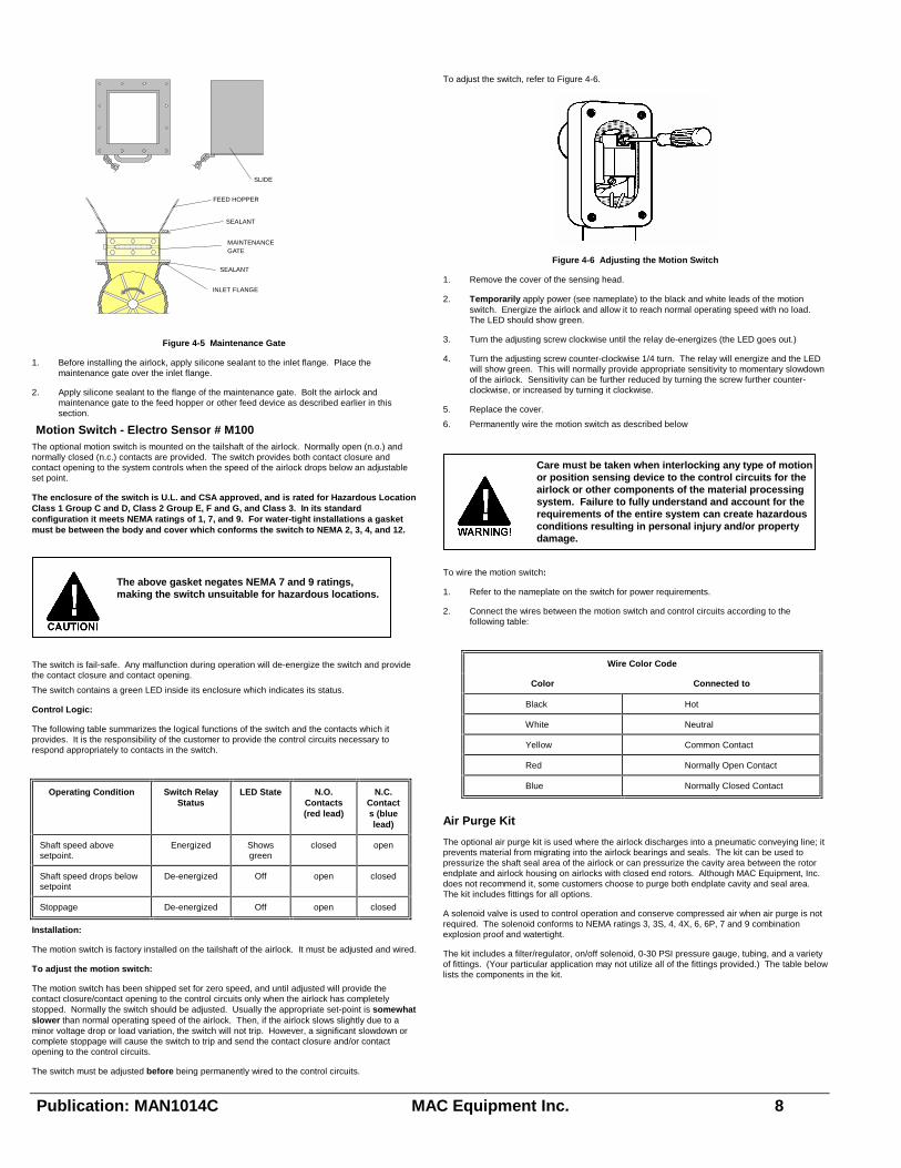
To adjust the switch, refer to Figure 4-6.
Figure 4-6 Adjusting the Motion Switch
1. Remove the cover of the sensing head.
2. Temporarily apply power (see nameplate) to the black and white leads of the motion switch. Energize the airlock and allow it to reach normal operating speed with no load. The LED should show green.
3. Turn the adjusting screw clockwise until the relay de-energizes (the LED goes out.)
4. Turn the adjusting screw counter-clockwise 1/4 turn. The relay will energize and the LED will show green. This will normally provide appropriate sensitivity to momentary slowdown of the airlock. Sensitivity can be further reduced by turning the screw further counter-clockwise, or increased by turning it clockwise.
5. Replace the cover.
6. Permanently wire the motion switch as described below
To wire the motion switch:
1. Refer to the nameplate on the switch for power requirements.
2. Connect the wires between the motion switch and control circuits according to the following table:
Wire Color Code
Color Connected to
Black Hot
White Neutral
Yellow Common Contact
Red Normally Open Contact
Blue Normally Closed Contact
Air Purge Kit
The optional air purge kit is used where the airlock discharges into a pneumatic conveying line; it prevents material from migrating into the airlock bearings and seals. The kit can be used to pressurize the shaft seal area of the airlock or can pressurize the cavity area between the rotor endplate and airlock housing on airlocks with closed end rotors. Although MAC Equipment, Inc. does not recommend it, some customers choose to purge both endplate cavity and seal area. The kit includes fittings for all options.
A solenoid valve is used to control operation and conserve compressed air when air purge is not required. The solenoid conforms to NEMA ratings 3, 3S, 4, 4X, 6, 6P, 7 and 9 combination explosion proof and watertight.
The kit includes a filter/regulator, on/off solenoid, 0-30 PSI pressure gauge, tubing, and a variety of fittings. (Your particular application may not utilize all of the fittings provided.) The table below lists the components in the kit.
Care must be taken when interlocking any type of motion or position sensing device to the control circuits for the airlock or other components of the material processing system. Failure to fully understand and account for the requirements of the entire system can create hazardous conditions resulting in personal injury and/or property damage.
SLIDE
FEED HOPPER
SEALANT
MAINTENANCEGATE
SEALANT
INLET FLANGE
The above gasket negates NEMA 7 and 9 ratings, making the switch unsuitable for hazardous locations.

Publication: MAN1014C MAC Equipment Inc. 9
QUANTITY
DESCRIPTION OF ITEM Shaft Seal Purge Only
Endplate Purge Only
Seal & Endplate Purges
1 3/8� Filter/Regulator 1 1 1
2 3/8� On-Off Solenoid 1 1 1
3 3/8� O.D. Poly-Flo Tubing 8 ft. 8 ft. 8 ft.
4 3/8� Poly-Flo - 1/4� MNPT
Connector 2 -- 2
5 3/8� Poly-Flo - 3/8� MNPT
Connector 2 4 4
6 3/8� Poly-Flo Union Tee -- -- 2
7 1/2� x 3/8� Galvanized
Reducer 1 1 1
8 Filter/Regulator Mount Bracket
1 1 1
9 3/8� x 2� Lg. Galvanized Nipple
3 3 3
10 3/8� NPT Galvanized Tee 1 1 1
11 Pressure Gauge, 0-30 PSI
1 1 1
Items 1, 2, 7, 8, 9, 10, and 11 are pre-assembled.
Install the air purge kit as described below. Refer to Figure 4-7 below.
3/8" POLY-FLO UNION TEE (6) -- POSITION AS CLOSE TO ENDPLATE AS POSSIBLE
VIEW SHOWING AIR PURGE TO BOTH PORTS
SOLENOID (2)
PRESSURE GAUGE (11)
1/2" FNPT COMPRESSED AIR CONNECTION (7)
FILTER/REGULATOR (1)
VIEW SHOWING AIR PURGE TO SHAFT SEAL PORTS ONLY
3/8" POLY FLOTUBING (3) - LEGSEQUAL LENGTH
VIEW SHOWING AIR PURGE TO ENDPLATE CAVITY PORT ONLY
SHAFT SEAL PORT
ENDPLATE CAVITY PORT
(4)
(4)
(4)
(5 )(4)
(5)
Figure 4-7 Typical Air Purge System
1. Mount the filter/regulator within 2 feet of the airlock and connect to compressed air supply.
2. Wire the solenoid to a controlled power source (see nameplate); the solenoid is normally closed, and must be energized to open and supply purge air whenever the pneumatic conveying line is pressurized or the airlock is running. If your system uses an air diverter valve to isolate the conveying air supply line, the solenoid must be energized whenever the diverter valve closes and air is supplied to the conveying line.
3. Connect 3/8� Poly-Flo tubing to the two shaft seal ports, one at each end of the airlock shaft. The legs to the two ports must be of equal length. Connect to the ports with the adapter fittings supplied.
The air purge system may also be connected in alternative configurations, as shown in Figure 4-7.
Pressure setting:
When the air purge system is operating, the filter/regulator pressure should be set at slightly above the pneumatic conveying line system pressure, according the chart below as a starting point. The final setting may be higher due to the particular application. The settings apply to both pressure and vacuum systems.
MODEL REGULATOR SETTING ABOVE PNEUMATIC CONVEYING LINE PRESSURE
Class 1 Rotor Clearance Class 2 Rotor Clearance
RAM06, RAM08
5 PSIG (14-18 SCFM)
5 PSIG (14-18 SCFM)
RAM10, RAM12
5 PSIG (14-18 SCFM)
10 PSIG (20-24 SCFM)
RAM14, RAM16
5 PSIG (14-18 SCFM)
15 PSIG (25-30 SCFM)
Safety Guard
The safety guard is used to block access to an exposed inlet or outlet throat.
Refer to Figure 4-8. A similar guard is available to protect an exposed inlet throat.
MATERIAL STORAGE
AIRLOCK
DISCHARGE GUARDWITH SAFETY GRATEON BOTTOM
DISCHARGE BIN ORTRUCK LOAD-OUT
Figure 4-8 Typical Discharge Guard.
1. Bolt the discharge guard onto the outlet throat of the airlock as shown.
Blow-thru adapter and surge hopper
INLETSTUB
OPTIONALFILTER
SUPPORTROD
VENTSOCK
SURGEHOPPER
AIRLOCK
BLOW-THRUADAPTER WITH LEGS
Figure 4-9 Blow-thru Adapter and Surge Hopper
Airlocks contain moving parts that will catch objects and shear them off. Contact with moving rotor blades will cause serious personal injury and/or property damage!

Publication: MAN1014C MAC Equipment Inc. 10
Blow Thru Adapter
The blow-thru adapter provides a transition between a pneumatic conveying line and the outlet throat of the airlock. It allows the airlock to discharge into the conveying line without loss of pressure.
The blow-thru adapter may be used with or without legs and surge hopper.
Support:
The blow-thru adapter with legs is normally capable of supporting the weight of the airlock, surge hopper, and typical accessories. If the airlock is properly supported by the feed device or other means, the blow-thru adapter may be supported by the airlock.
Surge Hopper
The surge hopper is used in applications where it is necessary to even-out the flow of product into the airlock. Such applications are: under screeners, sifters, screw conveyors, or tanks. Vent socks are mounted on the top of the surge hopper to control dusting from infeed of material. Vent socks also control blow-by air from a pneumatic conveying line. A filter may be used in lieu of the vent socks.
Support:
The surge hopper is installed on top of the inlet throat of the airlock and may be supported by the airlock.
To install the blow-thru adapter and surge hopper refer to Figure 4-9 and Figure 4-10.
SURGEHOPPER
BLOW-THRUADAPTER
PNEUMATICCONVEYING LINE
DIRECTIONOF ROTATION
SEALANT
SEALANT
AIRLOCK
Figure 4-10 Installation of the Blow-thru Adapter and Surge Hopper
1. Mount the blow-thru adapter to the floor (or other structural support capable of carrying the weight of the adapter, airlock, and all accessories to be used.)
2. Connect the adapter to other elements of the pneumatic conveying line.
3. Apply silicone sealant to the upper flange of the blow-thru adapter. Orient the airlock as shown, with the shaft perpendicular to the pneumatic conveying line. Bolt the outlet flange to the blow-thru adapter.
4. Apply silicone sealant to the inlet flange of the airlock. Orient the surge hopper with the inlet stub on the same side as the rotation of the airlock, as shown in Figure 4-9 and 4-10. Bolt the inlet flange of the airlock to the outlet flange of the surge hopper.
5. Connect the inlet stub of the surge hopper to the outlet of the screw feeder or other feed device. If the feed device is of a vibrating type, a flexible transition must be used. Do not support the weight of the feed device on the surge hopper; separate structural supports are required for the feed device and any related ductwork.
6. Install vent socks or optional filter on the top of the surge hopper. Fold the snap band on the vent sock to insert the sock into the hole on the surge hopper top. Fit the groove of the snap band to the edge of the hole and allow the band to snap in place. Repeat for each vent sock. Support the vent socks from the support rod.
INITIAL START-UP PROCEDURE
Pre-start checklist
1. Remove the drive guard. Make sure that the drive chain (or belt) is properly tensioned, (see "Checking and Adjusting Drive Chain").
2. Make sure the chain is properly lubricated.
3. Check the oil level in the drive gearbox and top off if necessary. Refer to the manufacturer�s instructions included with this manual.
4. Check that all pneumatic conveying line connections (if any) are tight. Check that all components of the conveying line are firmly anchored and properly supported.
5. Make sure that the airlock, feed device, and conveying line are free of foreign material.
6. Verify that all electrical connections have been properly made.
7. Replace all guards and covers.
Start-up
1. Energize the electrical service (and compressed air service if applicable.)
2. Jog the airlock quickly on and off. Verify that rotation occurs and that the direction of rotation is correct. Listen for sounds of unwanted mechanical contact. Investigate and correct if necessary.
3. Start the airlock and operate it for 15 minutes with no load. Check for excessive noise or other indications of improper operation. Investigate and correct if necessary.
4. Fill the feed hopper (or start other feed device). As material flows into the airlock, listen for excessive noise or other indications of improper operation. Investigate and correct if necessary. Observe the airlock carefully for the first hour of operation.
5. Verify that the current draw of the motor does not exceed its full load amp rating. (Refer to the nameplate on the motor for the rating.)
6. While the system is in operation, investigate for any apparent air leaks. Investigate and correct if necessary.
Normal Operation
Normal Operating Check List
Do not operate the airlock unless the following items have been checked and found to be satisfactory.
1. Airlock, feed devices, discharge devices, and all accessories are properly supported and securely fastened in place.
2. Connections to feed and discharge devices are secure and airtight.
3. The gearbox lubricant is in good condition and full.
4. The drive chain is properly lubricated.
5. All electrical devices and compressed air are properly connected and are undamaged.
6. All guards are properly in place and secure.
Normal Operating Parameters Use the form on the back page to record system information and operating conditions once start-up has been completed and the system is operating normally. Record changes in this information as they occur. This information will be useful to you and service personnel when troubleshooting the system or monitoring its performance.
Before inspecting or servicing this equipment perform an approved lockout-tagout procedure on the electrical service, the compressed air (or other gas) supply, or any other energy source.

Publication: MAN1014C MAC Equipment Inc. 11
MAINTENANCE AND ADJUSTMENT A regular program of maintenance and adjustment is essential to the proper operation and long life of your airlock.
Inspect the airlock regularly, or if excessive noise, binding, or other operating problems occur. Items which require inspection, maintenance, and adjustment include:
Rotors and rotor tips.
Seals and bearings.
Drive motor, drive gearbox, and drive chain.
Checking Rotor Clearances
Rotor clearances should be checked as part of a regular maintenance program. Rotor clearances must be within the allowable range as determined by �manufacturing class.� Each
airlock is built to a specific manufacturing class depending upon its size and operating conditions. Refer to the original Order Acknowledgment for the class of your airlock.
The table below shows the allowable clearances for each class.
Manufacturing Class Clearance Range Notes
Class 1 0.004� - 0.007� Standard Class for RAM Airlocks
Class 2 0.008� - 0.011� Standard Class for High Temperature Applications.
Class 3 0.012� - 0.018�
Class 4 0.019� - 0.024�
Check rotor clearance as follows. Refer to Figure 6-1
Figure 6-1 Checking Rotor Clearances
Disconnect the airlock from the feed and discharge devices to expose the inlet throat. It may be necessary to provide temporary support for the airlock or move it to a work area.
Remove the drive guard and disconnect the drive chain.
Mark each rotor blade with a number. Typically there are eight blades.
Insert a feeler gauge between the rotor tip and the airlock housing as shown in Figure 6-1. Check the clearance at each end of the blade and in the center. Check clearances at both the inlet and outlet throats of the airlock.
When all blades have been checked, reconnect the drive chain, replace the drive guard, and reinstall the airlock.
Adjusting Rotor Clearance
Some airlocks are furnished with rotor tips which can be adjusted, as follows. Refer to Figure 6-2 below.
Figure 6-2 Adjustable Rotor Tips.
1. Open the airlock, remove the drive guard and drive chain, and mark the rotor blades as described above under �Checking Rotor Clearance.�
2. Loosen but do not remove the anchor bolts holding the rotor tip to the blade.
3. Using two feeler gauges, insert one at each end of the blade between the rotor tip and the airlock housing on the inlet side.
4. Push rotor tip tight against the feeler gauges and tighten the anchor bolts.
5. Rotate the airlock so that the same blade appears on the outlet side. Check clearances at this location and adjust if necessary as described above in steps 3 and 4. One side or the other may be �tighter� than the other.
6. Adjust each of the remaining blades. Adjustment should be made at whichever side of the airlock is �tighter.�
7. Make a final check of clearances by rotating the rotor and checking each blade at each end and in the center. Check clearance at both sides of the housing.
8. When all blades have been checked, reconnect the drive chain, replace the drive guard, and reinstall the airlock.
Removing the RAM Rotor
The rotor must be removed and replaced if it is damaged or if clearances are out of specifications on airlocks with fixed tips.
Figure 6-3 Removing the Rotor
1. Determine which side of the airlock the rotor will be removed from. Normally this will be the drive side, but the procedure is similar for both sides.
2. Disconnect the airlock from the feed hopper or other feed device to expose the inlet throat. It may be necessary to disconnect discharge devices also and provide temporary support for the airlock.
3. Remove the drive guard and disconnect the drive chain. Remove the drive sprocket.
4. If the airlock has a motion switch on the tailshaft, remove it. Remove air purge piping from the drive end (if so equipped.)
5. Loosen and remove the bearing lock collar on the tailshaft. Remove the allen set screw from the collar. Loosen the collar by rotating in the direction opposite to shaft rotation. Use a drift pin in the plain hole (not the threaded set screw hole) and tap with a hammer to rotate the collar. Slide the bearing collar off the shaft. If the collar has made a groove on the shaft use emery cloth to remove it.
6. Loosen the shaft seal collar on the tailshaft. It is accessible through the opening in the endplate.
7. Remove the bolts holding the drive side endplate.
Before inspecting or servicing this equipment perform an approved lockout-tagout procedure on the electrical service, the compressed air (or other gas) supply, or any other energy source.
OUTLET THROAT
ROTOR
AIRLOCKHOUSING
INLET THROAT FEELER GAUGE
FEELER GAUGE

Publication: MAN1014C MAC Equipment Inc. 12
8. Thread three jack bolts in the three threaded holes in the endplate. Three of the endplate bolts can be used in an emergency. Three longer grade 5 or 8 bolts are recommended.
9. Tighten the jack bolts slowly and evenly in an alternating pattern until the endplate offset shoulder is pulled free of housing bore. Remove the endplate carefully so as not to damage the bearing and seals.
10. Carefully remove the rotor from the housing to avoid damage to rotor or housing.
NOTE: If the rotor is to be removed from the tail end, the same procedure will apply except that the drive sprocket will need to be removed also.
Replacing the Rotor
Refer to Figure 6-3.
1. Inspect the blade tips, shrouds, housing bore, endplate faces, rotor shaft, and keyway for burrs. If any burrs are found, file them smooth using a fine file and polish with an emery cloth.
2. Blow rotor, housing bore, and endplate faces clean of any foreign material.
3. Gently slide the rotor into the housing bore. Normally the rotor will not slide all of the way in freely. When the shaft is properly aligned pound on the end with a large rubber mallet; drive the rotor inwards just far enough to start the drive side endplate bolts. Once the bolts are started, tighten them evenly (in an alternating pattern) to pull the rotor and the endplate the rest of the way in.
4. Check the rotor to see if it is centered side to side in the housing. If it is not, tap the shaft to center the rotor. It may be necessary to loosen and reposition the bearing lock collars; re-tighten the collars.
5. Reposition and tighten the shaft seal collar. Tighten the allen screw first and then the two set screws. (For units with high temperature seals, refer to Figure 6-4.)
6. Turn the rotor by hand and make sure it rotates freely. Check the rotor clearances as described earlier in this section, and adjust if necessary.
7. Reconnect the drive chain, replace the drive guard, and reinstall the airlock. Reinstall air purge piping and motion switch (if so equipped.)
Replacing Bearings and TS-4 Seals
The MD Airlock uses the Imperial (ip) Adapter Mounted Dodge Unitized Sperical Roller Bearing Inserts. The bearings are regreaseable. See Dodge Information enclosed for proper grease selection. Operating temperature over 250^ requires high temperature grease, MAC part number: 328681.
Always replace seals and bearings at the same time. Seals should be replaced whenever the bearings are replaced, and vice versa.
Refer to Figure 6-4.
STANDARD ASSEMBLY HIGH TEMPERATUREASSEMBLY
STAINLESS STEEL SLEEVE
.015" MIN
.050" MAX
O-RING
SHAFT
QUADRINGS
ENDPLATE
TEFLONSLEEVE
BEARING
BEARINGLOCK COLLAR
SHAFT SEALCOLLAR
Figure 6-4 Replacing Bearings and Seals
1. Disconnect the airlock from the feed hopper or other feed device to expose the inlet throat. It may be necessary to disconnect discharge devices also and provide temporary support for the airlock.
2. Remove the drive guard and disconnect the drive chain. Remove motion switch and air purge piping (if so equipped.)
3. Remove the drive sprocket. Loosen bolts holding the back plate of the drive guard, slip it off the shaft, and swing it out of the way.
4. Loosen and remove the bearing lock collar on whichever end requires service. Remove the allen set screw from the collar. Loosen the collar by rotating in the direction opposite to shaft rotation. Use a drift pin in the plain hole (not the treaded set screw hole) and tap with a hammer to rotate the collar. Slide the bearing collar off the shaft. If the collar has made a groove on the shaft use emery cloth to remove it.
5. Loosen the shaft seal collar. It is accessible through the opening in the endplate.
6. Remove the bolts holding the endplate. Slide the endplate off the rotor shaft, using a puller if necessary. The bearing, shaft seal collar, Teflon sleeve, and quad ring seals will come out with the endplate.
7. Press the bearing out of the endplate; tap out the shaft seal collar and Teflon sleeve.
8. Remove the three quad ring seals.
9. Install new quad seals in the endplate. Install new Teflon seal and shaft seal collar by gently tapping them into place in the endplate.
10. Press a new bearing into the endplate.
11. Slide the endplate over the shaft; replace and tighten the bolts.
12. Replace and tighten the bearing lock collar.
13. Position the Teflon sleeve and shaft seal collar. Tighten the collar.
14. Replace the sprocket, reconnect the drive chain, replace the drive guard, and reinstall the airlock. Reinstall air purge piping and motion switch (if so equipped.)
Note: Installation of the high temperature assembly is similar to the above, except that a machined stainless steel sleeve replaces the shaft seal collar and Teflon sleeve
Checking and Adjusting Drive Chain
Check tension in the roller drive chain after every 200 hours of use. New chains will loosen as joints seat themselves, causing an initial elongation. Tension in all chains may change due to normal wear.
Refer to Figure 6-5 below.
Figure 6-5 Adjusting the Drive Chain
1. Remove the drive guard.
2. Check tension in chain. It should be installed fairly tight, with a slight amount of slack.
3. To adjust tension loosen the adjusting bolts and rotate the reducer mount. Adjust tension so that there is 3/8� to 1/2� deflection in the top of the chain when the bottom is tight.
Tighten the adjusting bolts.
4. Check alignment of sprockets. Place a straightedge along their finished sides. If they are not aligned, loosen the set screw on either sprocket and slide forwards or backwards on its shaft until alignment is correct.
5. Replace the drive guard.
Drive Motor and Gearbox
Inspect, lubricate, and service the drive motor and gearbox in accordance with the manufacturer�s
instructions included with this manual.
The gearbox is normally shipped dry and must be filled prior to operation of the airlock.

Publication: MAN1014C MAC Equipment Inc. 13
TROUBLESHOOTING
Requesting Service Help
If a problem arises, it is recommended that the customer first troubleshoot the system using the guide that follows.
Under some circumstances, service assistance may be required. If it becomes necessary to request service help call the MAC Equipment Service Manager at 1-888-821-2476.
When calling to request service help, please have the following information ready:
Essential Information:
1. MAC Equipment job number (located on the Order Acknowledgment)
2. Equipment model number(s)
3. Equipment serial number(s)
4. Operating temperature
5. Type of material being conveyed
6. Airlock RPM
7. Method of feeding the valve
8. Drive motor amperage reading
Other Pertinent Information:
9. Blower speed
10. Blower pressure switch setting
11. Blower motor amperage reading
12. Vacuum or pressure gauge reading
13. Conveying line run length
a. Horizontal Run
b. Vertical Run
c. Number of elbows.
Occasionally, a service trip may be necessary. There will be a charge for such a trip unless it is a warranty trip or covered by a pre-paid start-up agreement. The service department can provide information on service trip rates and billing procedures.
Troubleshooting Guide
POSSIBLE CAUSE SOLUTION
1. Squealing during operation
a) Incorrect direction of rotation
Check decals on airlock housing and/or drive guard for correct direction. Rewire motor if necessary to correct.
b) Insufficient rotor clearance
Check clearance and adjust as necessary as described in section "Checking Rotor Clearances".
c) Drive chain rubbing on guard
Adjust guard and/or sprocket position.
d) Drive shaft rubbing on guard
Adjust guard position.
e) Bearing failure Remove and inspect bearings. Replace if necessary as described in section "Replacing Bearings and Seals".
f) Rotor incorrectly positioned axially in housing
Inspect and adjust rotor position as described in section "Checking Rotor Clearance". If rotor position is changed, sprockets must be realigned.
g) None of the above
Call for service assistance.
2. Airlock does not rotate
a) No power to airlock
b) Faulty motor
Check fuses.
Check motor heater settings.
Check motor starter operation.
Check motor for open windings; replace if necessary.
c) Chain not connected
Check chain for broken link; repair link or replace chain and reconnect.
d) Foreign object caught in inlet throat
Inspect and remove.
e) Faulty or damaged gearbox
f) None of the above
Check to see if motor is turning, but gearbox is not. If so, replace gearbox.
Call for service assistance.
3. Material will not flow through the airlock
a) Supply source or feed device plugged, empty, or not operating
Check supply source.
b) Airlock turning too fast
Replace sprockets to achieve proper RPM.
c) Airlock not rotating
d) Excessive moisture in Product
See item 2 above.
Check flange connections for proper seal.
Check process for proper product condition.
e) Excessive blow-by air
Check and adjust rotor clearances.
Install vented shear protector.
f) None of the above
Call for service assistance.
4. Short seal life
a). Airlock is not oriented correctly to conveying line
Reinstall airlock with correct orientation, as described in section "Installation of Blow Thru Adapter".
b). Incorrect air purge pressure
Adjust air purge pressure as described in section "Air Purge Kit".
c). Seal out of position
Inspect and reposition seal.
d). None of the above
Call for service assistance.
Before inspecting or servicing this equipment perform an approved lockout-tagout procedure on both the electrical service and the compressed air (or other gas) supply.

Publication: MAN1014C MAC Equipment Inc. 14
ORDERING SPARE PARTS To order by Phone, dial 1-888-821-2476. When placing an order for spare parts always give the
following:
1. Model Number
2. Serial Number
3. Part Description
4. Part Number
5. Quantity Required
6. MAC Job Number (or Sales Order Number)
Order Acknowledgement
JOB INFORMATION
MAC Equipment Job No. ____________________________ Customer Purchase Order No.: _______________________ Purchased Date: __________________________________ Customer Drawing No.: _____________________________ (If Supplied)
AIRLOCK INFORMATION
Airlock Model No:__________________________________ Airlock Rotor Style: ________________________________ Airlock Drive Supplied by MAC Equipment? Yes No Airlock Drive H.P.__________________Airlock Drive RPM: ________ Airlock Air Purge: __________________________________ Seal Only Cavity Only Seal and Cavity Purge PSIG: ______ Airlock Serial No(s).: _______________________________ Airlock Tag No(s).: _________________________________
CONVEYING LINE INFORMATION
Material Conveyed: ________________________________ Conveying Line Size: _______________________________ Line Pressure (PSIG) or Vacuum (� HG): _______________
MODIFICATIONS & NOTES
______________________________________ ______________________________________ ______________________________________
SALES ORDER NO.
RVSN
DATE
PAGE
CUSTOMER ORDER NO.
ORDER DATE
SALES CAT.
TAXABLE
METHOD OF SHIPMENT
F.O.B.
PPD
S.A.
TERMS

Publication: MAN1014C MAC Equipment Inc. 15
SPARE PARTSAirlock
Item
Description Part Number
1 Airlock Housing - - - - - - - - - - - - - - - - - - - - - - - -
2 End Plate - - - - - - - - - - - - - - - - - - - - - - - -
TS-4 Seal Assembly (items 3 through 5)
3 Sleeve - - - - - - - - - - - - - - - - - - - - - - - -
4 Quad Rings - - - - - - - - - - - - - - - - - - - - - - - -
5 Shaft Seal Collar - - - - - - - - - - - - - - - - - - - - - - - -
6 Bearing with Lock Collar
7 Rotor - standard - - - - - - - - - - - - - - - - - - - - - - - -
adjustable tip - - - - - - - - - - - - - - - - - - - - - - - -
closed end - - - - - - - - - - - - - - - - - - - - - - - -
8 Adjustable Rotor Tips
9 Mount Channel - - - - - - - - - - - - - - - - - - - - - - - -
10 Reducer Plate - - - - - - - - - - - - - - - - - - - - - - - -
11 Gearmotor - - - - - - - - - - - - - - - - - - - - - - - -
12 Guard Back - - - - - - - - - - - - - - - - - - - - - - - -
13 Guard Front - - - - - - - - - - - - - - - - - - - - - - - -


![Investigation of Purging and Airlock Contamination of ... · NIOSH [2014]. Investigation of Purging and Airlock Contamination of Mobile Refuge Alternatives. By Bauer ER, Matty TJ,](https://img.dokumen.tips/doc/110x75/5ed07f145eaa90553a7cafb9/investigation-of-purging-and-airlock-contamination-of-niosh-2014-investigation.jpg)