Embed Size (px)
Citation preview

MASSACRUSE1.'TS -BAY TR.!--1.~SPO R TATIO N AUTHORITY
RAILROAD OPERATIONS DIRECTORATE
The :lttached Specifications are required for any construction and/or related activities on~ over7 under7 within or adjacent to railroad "property owned or controlled by the Massachusetts Bay Transportation AlIthonty. They are intended to provide general guidelines and safeguards. "~hmen /\." of Construction Guidelines and Procedures contains a summa.ry:.:-of' MBT A Railroad Operations SEecifications which may be req~ireiL tn: is the responsibility of the Contractor:.t~ obtain all the necessary sp.ecifications" for each project. " .."
"'"'''Y'OQ" ~ . .,., ...
AOO898 -J77

1
n.
.---GWDELJNES AND PROCEDURES FOR CONSTRUCUON ON META RAILROAD PROPERTY .
This general specifiCltion outlines the immediate design requirements and methodology for progressing construction activities on MBT A Railroad Property.
MAI1'ITENANCE AND PROTECTION OF RAILROAD TRAFFIC
This specifiCltion will be included in AI I. work requirements on h-fBTA Railroad Property, and covers rules. requirements, and protective services for any construction-related activity on MBTA Railroad Property. Supplememal specifications are listed below:
m. INStJRANCE SPECIFTCA nONS
This ~ecification details required insurance coverages and limits of the MBTA and Railroad Company(s).
IV. PTPELThiE OCCUPANCX SPECIFTCA TIONS
v.
This specification details requirements for all pipeline borings/jackings and open C.ltS on or adjacent to MBTA Railroad Property, as well as requirements for plan submittals.
SPECTFTCA nONS FOR WIRE. CONDUIT AND CABLE OCCupA nONS
This specIfication details requirements for clearances and installationS of parallel and overhead crossings on MBT A Railroad Property, as well as requirements for plan submittals.
A00898 - 178

VI. BRIDGE ERECTION. DEMOLmON AND HOISTING OPERATIONS
This specification details plan preparation for demolition and/or hoisting and erection of strucrures on and over MBT A Railroad Property.
vn. TEMPORARY SHEETING AND SHORING
This specification details requirements for plan preparation and calculations necessary for sheeting and shoring for construction on or adjacent to MBTA Railroad Property.
vm. BLASTING SPECIFfCATIONS
This specification outlines submittals. details and requirements for blasting on or adjacent to MBTA Railroad Property.
IX. TEMPORARY PROTECTION SHIELDS FOR DEMOLmON AND CONSTRUcnON
x
. , This specification outlines criteria for plan prep~-ation related to protection of MBTA Railroad Property when work takes place on overhead strUctures.
INDUSTRIAL SIDE TRACK SPECIFICA TrONS
This specification outlines minimal requirements for materials and installation submission for private railroad side tracks up to MBT A property line andlor clearance point. Other provisions. site-specific, may be required, including signal protection maintenance and protection of railroad traffic.
XI. RIGHT OF WAY FENCING SPECIFICA nONS
This specific:ltion details the requirements for the materials. construction and installation of standard right of way fence.
XII. TEST BORING SPECIFICA nONS
This specification outlines procedures ana re"quirements for the performance of test borings on ~IBTA Railroad Property.
A00898 -179

XIII.
XIV.
FIBER OPTIC CABT E spECIFICA TrONS
This specification details requirementS for design and instal1ation of fiber optic cables on MBTA Railroad Property; and is modified by site-spedfic requirements, including the construction methodology. location and type of fiber optic cables and protection conduits.
RAILROAD OPERATIONS BOOK OF STANDARD PLANS, TRACK AND ROADWAY, MW-l SPECIFICATIONS FOR CONSTRUCOON AND MAINTENANCE OF TRACK.
Certain coDStnlction activities may require obtaining this comprebensive package if rail construction details and requirements are related to the track operation.
xv. COMMUTER RAIL DESIGN STANDARDS
. .
A00898-180

MASSACHUSETTS BAY TRANSPORTATION AUTHORITY
RAILROAD OPERATIONS DIRECTORATE
I
GUIDELINES AND PROCEDURES
FOR CONSTRUCTION ON
MBTA RAILROAD PROPERTY
MAY 1994
SECTION 1. SCOPE
1.01 These specifications provide general safeguards to railroad property owned or controlled by the Massachusetts Bay Transportation Authority and to railroad operations upon that property during the performance of construction and/or related activities on, over, under, within or adjacent to the railroad property. They are intended as guidelines and do not represent all legal requirements which are or may be associated with construction and/or related activities. The MBTA reserves the right to require additional information and clarification and to make unilateral changes to these specifications at any time, at its sole discretion.
SECTION 2 PEFINlTIONS
MBTA
RAILROAD COMPANY
MBTA RAILROAD PROPERTY
OWNER
U11UTY
GOVERNMENT
Massachusetts Bay Transportation Authority
The particular reference for the purpose of these specifications is the railroad company which maintains and/or operates or has trackage rights on the subject MBTA Railroad Property, including, but not limited to:
-Massachusetts Bay Transportation Authority ("MBTA") -Providence and Worcester Railroad ("P&W") -National Railroad Passenger Corporation ("Amtrak") -Consolidated Rail Corporation ("Conrail") -The Boston and Maine Corporation, The Springfield Terminal Railway Company, its affiliates, successors and assigns ("B&M")
-Bay Colony Railroad Corporation ("Bay Colony")
All railroad rights of way and adjacent lands owned and/or controlled by the MBTA.
The individual, utility, government, or corporation having title to the structure to be constructed upon, over or adjacent to railroad property owned or controlled by the MBT A.
Public or private communication, water, sewer, electric, gas and petroleum companies or other entity governed by the Massachusetts Department of Public Utilities.
Federal, State, Town, City, County and other forms of government.
AOO898- 182

CORPORATION
INDIVIDUAL
CONfRACTOR
OWNER OR ITS CONTRACTOR
Any firm duly incorporated under laws of a state government.
Any party not defined by "Owner, Utility, Government or Corporation".
The individual, partnership, firm, corporation or any combination thereof, or joint venture, contracting with a Utility, Government, Firm, Company, Corporation or Individual for work to be done on, over, under, within or adjacent to MBTA Railroad Property.
As used in these specifications, does not affect the responsibilities of either party for work conducted on, over, under, within or adjacent to MBTA Railroad Property.
SECTION 3. SUBMITI' AI.S
3.01 INlTIAL CONTACT
A The MBTA owns the majority of the railroad lines in eastern Massachusetts. Many of these railroad lines are operated for passenger service, using a Railroad Company as an operating and maintaining contractor. Some of the railroad lines are used for freight-only service, operated and maintained by other Railroad Company(s). In most instances, both passenger and freight service are operated over the same railroad lines.
B. All of the MBT A railroad lines are maintained by a designated Railroad Company(s), excepting rapid transit and light rail lines. The maintaining Railroad Company(s) has rights and responsibilities, in addition to the MBT A's property owner's rights.
C. To obtain further information concerning License Agreements, Easements, Licenses for Entry, and performance of construction-related activities which affect MBTA Railroad Property, a written request must be forwarded to:
Director of Real Estate Ten Park Plaza Boston, MA 02116
The Director of Real Estate is also the contact person for information concerning rapid transit and light rail lines. However, no part of these instructions or specifications are appJicable to rapid transit or light rail lines.
A00898 - 183

SECTION 4. PLANS AND SPECIFICA nONS
4.01 SCOPE: It is the intent of the MBTA to eliminate or minimize any risk involved with construction or related activities on, over, under, within or adjacent to MBTA Railroad Property. Therefore, MBTA approval and frequently one or more Railroad Company(s) approval of construction plans and specifications for all phases of a proposed project affecting MBTA Railroad Property is required.
4.02 GENERAL: The applicant must provide six (6) sets of plans and specifications to the Director of Real Estate. These plans and specifications must meet the approval of the Railroad Company(s) and the MBTA prior to the start of construction. These plans are to be prepared in sizes as small as possible and are to be folded to an 8-1/2 inch by 11 inch size (folded dimensions) with a 1-1/2 inch margin on the left side and a 1 inch margin on the top.
A After folding, the title block and other identification of the plans shall be visible at the lower right comer, without the necessity of unfolding. Each plan shall bear an individually identifying number and an original date, together with subsequent revision dates, clearly identified on the plan.
B. All plans are to be individually folded or rolled and where more than one plan is involved, they shall be assembled into complete sets before submission to the MBTA
4.03 PlANS: The plans are to show all the work which may affect MBTA Railroad Property, and contain a location map and plan view of the project, with appropriate cross sections and sufficient details. The proposed construction or related activities must be located with respect to top of rail (vertical) and center line of track (horizontal). The plan must also include railroad stationing, property lines and subsurface soil conditions. The subsurface information is to be in the form of boring logs with the borings located on the plan view. (The purchase of railroad valuation plans may be arranged by contacting MBTA Engineering offices at 722-3448).
4.04 SPECIFICATIONS: The specifications summarized on Attachment "A" attached hereto are the Standard Specifications of the MBTA Railroad Operations Department and apply to all types of construction work affecting MBTA Railroad Property.
A In addition to "Maintenance and Protection of Railroad Traffic" and "Insurance Specifications" which are required for all work on, over,
A00898-184

under, within or adjacent to MBTA Railroad Property, certain other Specifications contained in Attachment "A" shall be incorporated into construction/engineering submittals when deemed necessary by the MBTA and/or Railroad Company(s). (The purchase of additional specifications may be arranged by contacting MBTA offices at 722-3448).
SECTION 5. SUBMISSION IREVIEW
5.01 An initial submission of six (6) sets of plans and specifications for MBTA review must be forwarded to the Director of Real Estate, along with a completed MBTA Application for Enny (Attachment "B"). The submission will be circulated for review and comment to MBTA departments which may be impacted by the proposed project. If approved by the MBT A, an additional submission for the Railroad Company(s) review may be requested by the Director of Real Estate or his designee.
5.02 The applicant is advised that the MBTA's initial review process requires a minimum forty-five (45) day period, prior to the Railroad Company(s) involvement, and additional processing time may be required for specific documents (See Section 9).
SECTION 6. INSPECI10NS/PAYMENTS
6.01 The MBTA may inspect all projects affecting MBTA Railroad Property at least twice, at the applicant's sole expense. The actual number of MBTA inspections will depend on the size and complexity of the project.
6.02 The MBTA may utilize Railroad Company inspectors and flagmen for daily inspection and protection of rail traffic during the term of the construction period or related activities. The Owner or Contractor will be responsible for advance payment of all associated fees.
6.03 Advance payments to the MBTA for construction/engineering review of plans and specifications by MBTA staff must be submitted when initial contact is made with the Director of Real Estate. Payments shall be in the form of check or money order, made payable to the Massachusetts Bay Transportation Authority.
AOO89S-1S5

6.04 Advance payments covenng the services for Railroad Company(s) construction/ engineering review of plans and specifications, or services of an inspector or flagman, will be paid directlv to the Railroad Company(s). The MBTA will advise when such services are required, and the Railroad Company(s) will advise of the amount of the required advance payment.
SECTION 7. EXAMINA nON OF PLANS OR PROPERTY
7.01 The Contractor/Applicant shall have no claim for any differences between MBTA valuation plans and the actual conditions encountered in the field.
SECTION 8. INSURANCE AND INDEMNlFICA nON
8.01 Prior to entry upon MBTA Railroad Property, insurance will be provided to and approved by the MBT A and affected Railroad Company( s), as outlined in "Insurance Specifications. "
8.02 Additionally, all MBTA Licenses and Letters of Authorization contain a clause for indemnifying MBTA and the Railroad Company( s) from and against any and all liabilities, losses, damages, costs, expenses, causes of action, suits, claims, demands and/or judgments of any nature whatsoever that may be imposed upon or incurred by or assened against the MBTA or the Railroad Company(s).
SECTION 9. LEGAL DOCUMENTS FOR TEMPORARY AND PERMANENT INSTALLA nONS
9.01 The nature of entry upon or installation within MBTA Railroad Property will determine the authorizing document to be issued. listed below are brief descriptions of MBTA documents:
A License for En to': Authorizes shon-term entry for purposes of survey, inspection, test borings, access, etc. One-time administrative/engineering/legal review fee.
B. License Agreement: Authorizes installations, subject to termination clause, if Applicant chooses not to pursue an Easement. One-time administrative/engineering/legal review fee as well as annual rental fee.
A00898 - 186

C. Easement: Authorizes permanent installations in form suitable for recording at Regisny Deeds. All easements are non-exclusive and subject to relocation at the Owner's expense, for mass transportation purposes.
1. Easements must receive MBTA Board of Directors approval, which involves considerable time. Once approved by the Board of Directors and upon payment in full to the MBTA, a License for Construction is issued. Upon final inspection and acceptance of the installation by the MBTA the Easement document is issued.
2. Permanent Subsurface Easement widths are limited to a maximum three-foot distance on either side of the occupation.
3. a) A one-time administrative/engineering/legal review fee, in addition to value of easement, as established by independent appraisal conducted at the Applicant's expense.
b) If easement size is minimal, as determined by the MBT A, a fIXed fee, encompassing administrative/ engineering/legal review fees and value of easement shall be assessed.
D. Letter of Authorization: Authorizes installations and construction activities within the confines of a public way over or under which MBTA railroad tracks cross. One-time administrative/engineering/legal review fee.
AOO898 -187

I.
II.
ATTACHMENT "A"
SUMMARY OF MBTA RAILROAD OPERATIONS SPECIFICATIONS
GUIDELINES AND PROCEDURES FOR CONSTRUCTION ON MBTA RAILROAD PROPERTY
This general specification outlines the immediate design requirements and methodology for progressing construction activities on MBT A Railroad Property.
MAINlENANCE AND PROTECTION OF RAILROAD TRAFFIC
This specification will be included in ALL work requirements on MBTA Railroad Property, and covers rules, requirements, and protective services for any construction-related activity on MBTA Railroad Property. Supplemental specifications are listed below.
Ill. INSURANCE SPECIFICATIONS
This specification details required insurance coverages and limits of the MBTA and Railroad Company(s).
IV. PIPELINE OCCUPANCY SPECIFICATIONS
V.
This specification details requirements for all pipeline borings/jackings and open cuts on or adjacent to MBTA Railroad Property, as well as requirements for plan submittals.
SPECIFICA nONS FOR WIRE. CONDUIT AND CABLE OCCUPA nONS
This specification details requirements for clearances and installations of parallel and overhead crossings on MBTA Railroad Property, as well as requirements for plan submittals.
AOO898 -188

VI. BRIDGE ERECI10N. DEMOLITION AND HOISTING OPERATIONS
This specification details plan preparation for demolition and/or hoisting and erection of structures on and over MBTA Railroad Property.
VII. TEMPORARY SHEETING AND SHORING
This specification details requirements for plan preparation and calculations necessary for sheeting and shoring for construction on or adjacent to MBTA Railroad Property.
vm. BLASTING SPECIFICATIONS
This specification outlines submittals, details and requirements for blasting on or adjacent to MBTA Railroad Property.
IX. TEMPORARY PROTECTION SHIELDS FOR DEMOLmON AND CONSTRUCTION
x
This specification outlines criteria for plan preparation related to protection of MBTA Railroad Property when work takes place on overhead structures.
INDUSTRIAL SIDE TRACK SPECIFICA nONS
This specification outlines minimal requirements for materials and installation submission for private railroad side tracks up to MBTA property line and/or clearance point. Other provisions, site-specific, may be required, including signal protection maintenance and protection of railroad traffic.
XI. RIGHT OF WAY FENCING SPECIFICA nONS
This specification details the requirements for the materials, construction and installation of standard right of way fence.
XII. TEST BORING SPECIFICA nONS
This specification outlines procedures and requirements for the performance of test borings on MBT A Railroad Property.
A00898-189

XIll. FIBER OPTIC CABLE SPECIFICA nONS
This specification details requirements for design and installation of fiber optic cables on MBT A Railroad Property; and is modified by site-specific requirements, including the construction methodology, location and type of fiber optic cables and protection conduits.
XIV. RAILROAD OPERATIONS BOOK OF STANDARD PLANS. mACK AND ROADWAY. MW-l SPECIFICA nONS FOR CONSTRUCTION AND MAINTENANCE OF TRACK
Certain construction activities may require obtaining this comprehensive package if rail construction details and requirements are related to the track operation.
XV. COMMUTER RAIL DESIGN STANDARDS
A00898 - 190

ATTACBKEN'l' "B"
MASSACHUSETTS BAY TRANSPORTATION AUTHORITY APPLICATION FOR ENTRY UPON MBTA RAILROAD PROPERTY
1. Name of Applicant:
2. Type of Entity (Partnership, corporation, Proprietorship, Public Authority, etc.):
3. Hailing Address:
4. If incorporated, state of incorporation:
5. Proposed license term commencement date:
6. Proposed license term:
7. Brief description of construction (Including types of pipes and other attachments or ancillary facilities to be installed on HBTA Railroad Property) :
8. Brief description of purpose of entry and/or installation:
9. Nearest KBTA station:
10. County:
11. State:
12. Agents for licensee (applicant) for service of notice or process:
13. If applicant is self-insured, please provide limits of self-insurance and attach copies of authorizing legislation or certification thereof:
14. If applicant is authorized by public authority to enter into such license
AOO898 -191

agreement, please provide:
Motion, Resolution, or Ordinance No.:
Date of Adoption:
Adopted by:
15. Name and title of L~censee's officer authorized to sign agreement:
16. Is this occupancy within l~its of public road? Attach copies of applicant's franchise to occupy such space.
17. If occupancy is under, over, through or attached to undergrade or overhead bridge, who owns such bridge?
18. Type of occupancy (facility):
a) Exact length of HBTA Railroad Property to be burdened by occupancy:
b) Width of excavation facility on MBTA Railroad Property:
c) Number of manholes:
A. Aeri.al or 1Ulderground wi.re and cable:
(1) Telephone and other communication cables:
Number of cables:
Number of pairs/cable:
Are these composite coaxial cables?
(2) Power cables:
Number of cables/size:
Number of volts per conductor:
Are these pipe-type cables consisting of 1 or more high voltage cables encased in steel pipe under inert oil pressure?
(3) Fiber optic cables:
Number of cables:
Number of distribution cables:
Number of transmission cables:
AOO898-192

Number of strands in each cable:
Number of repeater stations on MBTA Railroad Property:
Systems (Check one)
Transmission Distribution Sensor
(4) Number of spare or unoccupied ducts to be installed:
B. Pipes and Sewers
(1) Circular line carrying no pressure:
Number of pipes:
Number of inches of inside nominal diameter per pipe:
(2) Circular lines under pressure and carrying nonflammable, non-explosive, or non-combustible supporting materials, except coal and slurry:
Number of pipes:
Number of inches of inside nominal diameter per pipe:
(3) Circular lines under pressure and carrying flammable, explosive or combustible supporting material:
Number of pipes:
Number of inches of inside nominal diameter per pipe:
(4) Non-circular pipe:
(5) Will a pipe tunnel be constructed:
(6) Will pipe be supported by MBTA structures, bridges etc.?
Explain:
(7) Will pipe be attached to MBTA structures, bridges?
Explain:
A00898 - 193

c. Ancillary Facilities
NUJIIber of wooden poles to be installed on MBTA Railroad Property:
other wooden supporting. structures:
Steel supporting structures:
Explain:
Number of braces, stub poles:
Number of guy wires anchored on KBTA Railroad Property:
Number of span guy wires crossing MBTA Railroad Property:
D. Attachments
(1) Attachment of aerial wires and cables to poles or other structures of MBTA used in wire line construction or support:
Number of wires attached to MBTA cross-arm:
Voltage of wire:
Number of wires attached to Licensee's cross-arm or bracket:
Voltage of wire:
Number of cross-arms or brackets attached to MBTA poles:
(2) Attachment of aerial wires and cables to buildings or structures other than those used in wire line construction or support.
Number of wires or cables attached to MBTA' s building or structures:
(3) Attachment of cable terminals to poles, buildings, or structures including highway bridges railroad bridges over highways or other bridges of MBTA.
Number of cable terminals, loading coils, transformers or like devices attached:
Explain:
E. Guy wire crossings aDd overhanging cross-axms aDd power wires of pole lines outside MB~ right-of-way.
AOO898 -194

Number of guy wires crossing HBTA Railroad Property but not anchored thereon:
Number of cross-arms overhanging KBTA Railroad Property from poles located outside thereof:
Number of cross-arms on any pole:
It is hereby understood and agreed that the undersigned applicant will bear any and all costs associated with KBTA's preliminary and final engineering reV1ew in connection with this application. Any charges in excess of the initial advance payment will be billed directly to the address indicated in item #3.
Agent:
For: Name of Applicant
BY:
(Title)
(Date)
AOO898-195

ATIACHMENT "C"
REFERENCED STANDARDS AND SPECIFICATIONS
A Wherever standards or specifications issued by a recognized industry association or regulatory body are referenced in these Specificatio~ the reference shall be interpreted as incorporating the referenced standard or specification in total into these Specifications as applicable. In the event of a difference between referenced standard or specifications and these Specifications, the latter shall govern.
B. Technical Reference Abbreviations - References are made to recognized standards by use of the acronyms listed below. Addresses are included for convenience, and the accuracy of the addresses is not warranted:
AA The Aluminum Association 900 19th Street NW Washington, DC 20006
AAR The Association of American Railroads American Railroads Building 50 F Street NW Washington, DC 20001
AASHTO American Association of State Highway and Transportation Officials
444 North Capitol Street NW Suite 249 Washington, DC 20001
ACGIH American Conference of Governmental Industrial Hygienists
1330 Kemper Meadow Drive Cincinnati, OH 45240
ACI American Concrete Institute P.O. Box 19150 Detroit, MI48219
AOO898 -196

AFPA
AlA
AlSC
AlSI
AITC
ANSI
APA
APHA
AREA
ASCE
American Forest and Paper Association 1111 19th Street, NW Suite 700 Washington, DC 20036
American Insurance Association 1130 Connecticut Avenue NW Washington, DC 20036
American Institute of Steel Construction Inc. 1 East Wacker Drive Suite 1300 Chicago,IL 60601
American Iron and Steel Institute 1101 17th Street NW Suite 1300 Washington, DC 20036-4700
American Institute of Timber Construction 7012 South Revere Parkway Suite 140 Englewood, CO 80112
American National Standards Institute 11 West 42nd Street New York, NY 10036
American Plywood Association P.O. Box 11700 Tacoma, WA 98411
American Public Health Association 1015 15th Street NW Washington, DC 20005
American Railway Engineering Association 50 F Street N. W. Washington, D.C. 20001
American Society of Civil Engineers 345 East 47th Street New York, NY 10017
A00898 -197

ASHRAE American Society of Heating, Refrigerating and Air Conditioning Engineers
1791 Tullie Circle, NE Atlanta, GA 30329
ASME American Society of Mechanical Engineers 345 East 47th Street New York, NY 10017
ASTM American Society for Testing and Materials 1916 Race Street Philadelphia, PA 19103
AWPA American Wood Preservers' Association P.O. Box 286 Woodstock, MD 21163-0286
A WS American Welding Society 550 NW 42nd Avenue Miami, FL 33126
A WW A American Water Works Association, Inc. 6666 W. Quincy Avenue Denver, CO 80235
CSI Construction Specifications Institute 601 Madison Avenue Alexandria, VA 22314-1791
FHA Federal Highway Administration 400 7th Street SW Washington, DC 20590
FRA Federal Railroad Administration 400 7th Street SW Washington, DC 20590
ICBO International Conference of Building Officials 5360 Workman Mill Road Whittier, CA 90601
IIA Incinerator Institute of America 60 East 42nd Street New York, NY 10017
AOO898 -198

Mass-DEP Massachusetts Department of Environmental Protection 1 Winter Street Boston, MA 02018
Mass-DPS Massachusetts Department of Public Safety 1 Ashburton Place Boston, MA 02108
Mass-DPU Massachusetts Department of Public Utilities 100 Cambridge Street Boston, MA 02202
Mass-FPR Massachusetts Fire Prevention Regulation 1010 Commonwealth Avenue Boston, MA 02215
MHD Massachusetts Highway Department 10 Park Plaza Boston, MA 02116
NACE The National Association of Corrosion Engineers P.o. Box 218340 Houston, TX 77218-8340
NCMA National Concrete Masonry Association 2302 Horse Pen Road Herndon, VA 22071
NFP A National Fire Protection Association 1 Batterymarch Park Quincy, MA 02269
NSWMA National Solid Wastes Management Association 4301 Connecticut Avenue NW Suite 300 Washington, DC 20008
SJI Steel loist Institute 1205 48th Ave. North Suite A . Myrtle Beach, S.c. 29577
A00898 - 199

UL
USCG
Underwriter's Laboratories, Inc. 207 East Ohio Street Chicago, IL 60611
United States Coast Guard 2100 Second Street SW Washington, DC 20593-0001
When reference is made to the specifications or standards of any of the above organizations, federal agencies, trade associations, or others, it is made to the edition current.as of the date of approval of application.
A00898 -200

MASSACHUSETTS BAY TRANSPORTATION AUTHORITY
RAILROAD OPERATIONS DIRECTORATE
II
MAINTENANCE AND PROTECTION OF RAILROAD TRAFFIC
MAY 1994
AOO898-201

SECTION 1. GENERAL
1.01 The contractor should note that these specifications govern proposed work that involves construction on, over, under, within or adjacent to MBTA Railroad Property. Requirements must be strictly observed whenever the tracks, structures, or properties of the MBTA are involved or affected.
1.02 If the tracks or other facilities of the MBTA are endangered, the Contractor shall immediately perform such work as directed by the Railroad Company(s), and upon failure of the Contractor to carry out such orders immediately, the Railroad Company(s) may take whatever steps are necessary to restore safe conditions. The cost and expense to the Railroad Company(s) and/or MBTA of restoring safe conditions or of any damage to the MBTA's trains, tracks, or other facilities caused by the Contractors' or subcontractors' operations, shall be at the sole expense of the Contractor and will be collected as appropriate. This cost shall be paid for by the Contractor and may be deducted from any monies due and that may become due to the Contractor.
1.03 Before entering upon MBTA Railroad Property:
A. The Owner or its Contractor shall be fully informed of all requirements of the MBTA pertaining to the specific project and shall conduct all his work accordingly. Any questions relating to the requirements of the MBTA should be directed to the Chief Engineering Officer of the MBTA or his authorized representative.
B. The Owner or its Contractor shall execute an MBT A license for Entry, and shall provide the MBTA and Railroad Company(s) witb the information required in the "Insurance Specifications".
C. The Owner or its Contractor shall take note that if an excavation is to be made within a 2 to 1 slope line commencing 5.5 feet from the centerline of track, he shall submit the proposed method of soil stabilization for approval by the Chief Engineering Officer of the MBT A.
D. The Owner or its Contractor shall furnish detailed plans, for falsework, bracing, sheeting, or other supports adjacent to the tracks for approval by the Chief Engineering Officer of the MBTA and the Railroad Company(s), and the work shall be performed in accordance with "Temporary Sheeting and Shoring". All plans and calculations shall be stamped by a Registered Professional Engineer.
E. The Owner or its Contractor shall give written notice to the Chief Engineering Officer of the MBTA and the applicable Railroad Company(s)
AOO898 -202

at least 21 days in advance of starting work or locating equipment at the site.
F. The Owner or its Contractor shall make all necessary arrangements with the MBTA before entering upon MBTA Railroad Property.
1.04 After entering upon MBTA Railroad Property:
A The Owner or its Contractor shall have in his possession on the job site the contract plans and specifications which bear the stamp of approval of the MBTA Chief Engineering Officer or Railroad Company(s). The Owner or its Contractor shall conduct all his work according to these plans and specifications.
B. All work shall be performed and completed in a manner fully satisfactory to the MBTA Chief Engineering Officer or authorized representative(s). Railroad Company(s) inspection of the work shall be conducted at any time and the Owner or its Contractor shall cooperate fully with the MBTA and Railroad Company(s) representatives.
C. All equipment used by the Owner or its Contractor on MBTA Railroad Property may be inspected by the Railroad Company(s) and shall not be used if considered unsatisfactory by the Railroad Company(s) representative. Equipment of the Owner or its Contractor to be used adjacent to tracks shall be in first class condition so as to positively prevent any failure that would cause delay in the operation of trains or damage to MBTA or railroad facilities. Equipment shall not be placed or put into operation adjacent to a track without first obtaining the permission of the Railroad Company(s).
D. Operators of such equipment must be properly licensed and may be examined by the Railroad Company(s) representative to determine their fitness. If it is determined that they are unfit to work, then the Owner or its Contractor shall remove them from MBT A Railroad Property.
E. If the Chief Engineering Officer of the MBTA deems it necessary, the Owner or its Contractor shall furnish and erect in close proximity to the site of the work a suitable, furnished shelter with lights, heat, telephone, etc., for use by Railroad Company(s) personnel providing services to the Owner's or Contractor's work.
F. The Owner or its Contractor's work shall be performed in such manner that the tracks, train operations and appurtenances of the MBT A and the Railroad Company(s) will be safeguarded.
AOO898 -203
G. Open excavations shall be suitably planked and safeguarded when construction operations are not in progress.
H. Blasting will be permitted under or adjacent to tracks only after proof that blasting is required and all methods have been approved by the MBT A's Chief Engineering Officer and the Railroad Company(s). All blasting operations must comply with the MBTA's "Blasting Specifications".
I. The Owner or its Contractor shall be fully responsible for all damages arising from their failure to comply with the requirements of these specifications. Failure to comply may result in their removal from MBTA Railroad Property, at the MBTA's sole discretion.
SECI10N 2. RULES. REGULA nONS. ETC.
2.01 Railroad traffic shall be maintained at all times with safety and continuity, and the Contractor shall conduct all operations on, over, under, within or adjacent to MBTA Railroad Property within the rules, regulations, and requirements of the Railroad Company(s) and/or MBTA The Contractor shall be responsible for acquainting himself with such requirements as the Railroad Company(s) and/or MBTA may demand.
2.02 The Contractor shall obtain verification of the time and schedule of track occupancy from the Railroad Company(s) before proceeding with any construction or demolition work on, over, under, within or adjacent to MBTA Railroad Property. The work shall not proceed until the plans and method of procedure have been approved by the Chief Engineering Officer of the MBTA or his authorized representative.
2.03 All work to be done on, over, under, within or adjacent to MBTA Railroad Property shall be performed by the Contractor in a manner satisfactory to the MBTA and the Railroad Company(s), and shall be performed at such times and in such manner, as to not interfere with the movement of trains or operations upon the tracks of the MBTA The Contractor shall use all necessary care and precaution in order to avoid accidents, delay or interference with the MBTA's trains or other property.
2.04 The Contractor shall give written notice to the Railroad Company(s) at least twentyone (21) days prior to the commencement of any work, or any portion of the work, by the Contractor or his subcontractors on, over, under, within or adjacent to MBTA
AOO898 - 204

Railroad Property, in order that necessary arrangements may be made by the Railroad Company(s) to protect railroad operations.
2.05 If deemed necessary by the Railroad Company(s), it may assign an inspector and/or engineer who will be placed on the work site during the time the Contractor or any subcontractor is performing work on, over, under, within or adjacent to MBTA Railroad Property. The cost and expense will be paid directly by the contracting party with an advance deposit to the Railroad Company( s), unless otherwise approved.
2.06 Before proceeding with any construction or demolition work, on, over, under, within or adjacent to the MBT A's Railroad Property, a preconstruction meeting shall be held at which time the Contractor shall submit for approval of the MBTA and Railroad Company(s), plans, computations, and a detailed description of the method for accomplishing the construction work, including methods of protecting railroad operations. Such approval shall not serve in any way to relieve the Contractor of complete responsibility for the adequacy and safety of the referenced methods.
2.07 During any demolition procedure, the Contractor must provide an approved shield to prohibit all debris from falling onto MBTA Railroad Property. A protective fence must be erected at both ends of the project to prohibit trespassers from entering MBTA Railroad Property.
2.08 Cranes, shovels, or any other equipment shall be considered to be fouling the track when located in such position that failure of same with or without load, brings the equipment within the fouling limit. The Contractor's employees and equipment will not be permitted to work near overhead wires or apparatus.
2.09 The Contractor shall conduct his work and handle his equipment and materials so that no part of any equipment should foul an operated track or wire line without the written permission of the Railroad Company( s). When it becomes necessary for the Contractor to foul any track, he must give the Railroad Company( s) written notice of his intentions twenty-one (21) days in advance, so that if approved, arrangements may be made for proper protection of the Railroad Company(s).
2.10 The Contractor's equipment shall not be placed or put into operation adjacent to tracks without first obtaining permission from the Railroad Company(s). Under no circumstances shall any equipment or materials be placed or stored within fifteen
A00898 - 205

(15) feet from the centerline of the closest track.
2.11 Materials and equipment belonging to the Contractor shall not be stored on MBT A Railroad Property without first having obtained permission from the Railroad Company(s), and such permission will be on the condition that the MBTA and/or Railroad Company(s) will not be liable for damage to such materials and equipment from any cause. The Contractor shall keep the tracks adjacent to the site clear of all refuse and debris that may accumulate from construction operatio~ and shall leave the MBTA Railroad Property in the condition existing before construction commencement. Equipment repair, refueling or extended storage is prohibited on MBTA Railroad Property.
2.12 The Contractor shall consult the Railroad Company(s) in order to determine the type of protection required to insure safety and continuity of railroad operations. The railroad field engineer may assign track foremen, flagmen, signalmen or other employees deemed necessary for protective services by the Railroad Company(s), to insure the safety of trains and MBT A Railroad Property. The cost of same shall be paid directly by the contracting pany with an advance deposit to the Railroad Company(s), unless otherwise approved.
2.13 The provision of such protective services, and other precautionary measures, shall not relieve the Contractor from liability for the cost of any and all damages caused by his operations.
2.14 The Railroad Company(s) will require protection during all periods when the Contractor is working on, over, under, within or adjacent to MBT A Railroad Property or as may be deemed necessary. When protection is required, the Contractor shall make the request in writing to the Railroad Company( s) at least twenty-one (21) days before such protection is required.
2.15 The Contractor shall not bill the Railroad Company(s) or MBTA for any work which he may perform, unless the Railroad Company(s) or MBTA authorizes the said work in writing. This work must be to the benefit of the MBTA or Railroad Company(s).
2.16 The Contractor, subcontractor and respective employees who will come within the limits of the MBTA Railroad Property, must first attend the Railroad Company(s) Safety Orientation Class. They are required to comply with the Railroad Company(s) Safety Requirements throughout the entire construction period. All costs associated
}\00898 - 206

with compliance of the Railroad Company(s) Safety Requirements will be at the sole expense of the Contractor and subcontractors.
A The Contractor for the project must appoint a qualified person who will be designated as a Safety Representative. He must be approved by the Railroad Company(s) Safety Representative. The Contractor's designee will be responsible to give Safety Orientation to the Contractor's/subcontractor's employees who will come onto the MBTA's Railroad Property for short periods of time after the initial Safety Orientation Class has been given by the Railroad Company(s). The Contractor's designee will keep the Railroad Company(s) Safety Representative informed of the temporary employees who received Safety Orientation. The Railroad Company(s) Safety Orientation aass will be repeated when employee turnover or groups of Contractor's and subcontractor's employees are such that another Railroad Company(s) Safety Orientation Qass is justified.
B. Contractors will follow established safety procedures and remain 15 feet or more from the centerline of the closest track. When it becomes necessary for Contractors to encroach on this 15 foot limitation, the proper fouling procedures will be arranged with the Railroad Company(s).
C. Contractors will establish the 15 foot foul line by installing stakes and taping off the area prior to beginning work.
2.17 Upon completion of the work, the Contractor shall remove from the MBT A Railroad Property, all machinery, equipment, surplus materials, falsework, rubbish, temporary buildings and other property of the Contractor, or any subcontractor, and shall leave MBTA Railroad Property in a condition satisfactory to the MBTA and Railroad Company(s). Failure to comply will result in Railroad Company(s) forces restoring MBTA Railroad Property at the Contractor's expense.
2.18 The Contractor will pay the Railroad Company(s) directly, for all protective services unless otherwise approved. The services are performed to insure safe operation of trains when construction work WOUld, in the Railroad Company(s) opinion, be a hazard.
SECIlON 3. DEFINITION OF HAZARD
3.01 Protection Services will be required whenever the Contractor is performing work on, over, under, within or adjacent to MBTA Railroad Property. This will include
AOO898-207

excavating, sheeting, shoring, erection, removal of forms, handling material, using equipment which by swinging or by failure could foul the track, and when any other type of work being performed, in the opinion of the Railroad Company(s), requires such service.
3.02 Railroad operations will be considered subject to hazard when explosives are used in the vicinity of MBTA Railroad Property during the driving or pulling of sheeting for footings adjacent to a track, when erecting structural steel across or adjacent to a track, when operations involve swinging booms or chutes that could in any way come doser than 15 feet to the center line of a track or wire line. None of these or similar operations, shall be carried on without Railroad Company(s) protective services personnel on site.
3.03 A signal line or communication line shall be considered fouled and subject to hazard when any object is brought closer than ten (10) feet to any wire or cable. An electrical supply line shall be considered fouled and subject to hazard when any object is brought closer than ten (10) feet to any wire of the line.
3.04 As excavation approaches pipes, conduits, or other underground structures on or adjacent to MBTA Railroad Property, digging by machinery shall be discontinued and the excavation shall continue by means of hand tools. AlI existing pipes, poles, wires, fences, property line markers, and other structures, which the MBTA and/or Railroad Company(s) decides must be preserved in place, -shall be carefully protected from damage by the Contractor or its Owner. Should such items be damaged, they shall be restored by the Railroad Company(s), at the Owner's or Contractor's sole expense to the original condition prior to construction commencement. If any excavation is taken beyond the work limit indicated on the approved plans or prescribed herein, the Owner or its Contractor shall backfilI and compact to the satisfaction of the Railroad Company(s) at his own expense.
SECTION 4. BACKFILL
4.01 Backfilling
A All backfill material adjacent to any Railroad Company(s) facility shall be approved by the Railroad Company(s). Backfill material shall be free from hard lumps and clods larger than 3 inches in diameter, and free from large rocks or stumps. Uniformly fine material shall be placed next to any pipe liable to dent or break.
AOO898-208

B. All backfill material shall be compacted at near optimum moisture content, in layers not exceeding 6 inches in compacted thickness by pneumatic tampers, vibrator compactors, or other approved means to the base of the railroad subgrade. Material shall be compacted to not less than 95 percent of AASHTO T 99, Method C. The Contractor will be required to supply to the job site, ballast stone (AREA #4) to be installed by the Railroad Company(s).
4.02 Certification
The Owner or its Contractor shall provide testing, through the use of a testing lab or Professional Engineer, to insure that the inplace density of the backfill meets or exceeds the requirements of Section 4.01(B). Written certification of the tests shall be given to the Railroad Company(s) immediately upon completion of the test.
4.03 Alternate
In the case of an open cut crossing of the MBTA Railroad Property, the Owner or its Contractor may backfill with concrete having a three-day compressive strength of 1000 psi to the base of the track subgrade. This may be used in lieu of providing the cenification of proper compaction when using gravel backfill. The Owner or its Contractor will be required to supply to the job site, ballast stone (AREA #4) to be installed by the Railroad Company(s).
SECIlON 5. CLEARANCES
5.01 Staging, falsework, or forms shall at all times be maintained with a minimum vertical clearance of 22'6" above top of the high rail and a minimum horizontal clearance of 15' from the center line of track.
SECIlON 6. PROTECTION SERVICES
6.01 The MBTA shall require railroad inspection and may require railroad flagging. Prior to start of any work on MBTA Railroad Property, the Owner or its Contractor shall submit a deposit in the amount required by the Railroad Company(s). If Railroad Company(s) expenses are greater than the amount of deposit, the Owner or its Contractor shall reimburse the Railroad Company(s) for the balance when billed, and, if the Railroad Company(s) expenses are less than the amount of deposit, the
AOO898 ·209

" Railroad Company(s) will refund the balance to the Owner or its Contractor. The Railroad Company(s) reserves the right to request additional deposits as project work progresses.
6.02 If the MBTA or Railroad Company(s) determines that flagmen are necessary, the number required shall be on duty at the site during the hours of hazard described under Section 3. No work shan be performed if fla&men are required but are not on duty.
6.03 It shall be the responsibility of the Owner or its Contractor to keep the MBTA and Railroad Company(s) informed at all times when the Owner or its Contractor shall be working on, over, under, within or adjacent to MBTA Railroad Property and creating the hazards described under Section 3. Failure of the Owner or its Contractor to give the MBTA and Railroad Company(s) suitable advance notice of hazardous operation shall result in the shut down of the work by the Railroad Company(s}, until such time as sufficient number of flagmen are on duty at the site. If this becomes a repeat occurrence, the Contractor will be removed from the project.
6.04 The Railroad Company(s) will make its best effort to provide protective services personnel. Should the situation arise where such personnel are not available, Contractor operations must cease. The Railroad Company(s) is not liable for any monetary claims incurred during the absence of protective services personnel.
SECTION 7. INSPECTION
7.01 If deemed necessary by the Chief Engineering Officer of the MBTA, the MBTA will furnish and assign an engineer(s) for inspection and the Railroad Company(s) will furnish an appropriate inspector for general inspection purposes or for general protection of MBTA Railroad Property and operations during construction. All protection services will be at the expense of the Owner or its Contractor.
SECTION 8. EXTRA-COl\T'fRACf SERVICES
8.01 Temporary and permanent changes of tracks and all railroad utilities made necessary by the work of the Contractor, will be made by the MBTA or Railroad Company(s)
AOO898-210

at the expense of the Owner or its Contractor.
8.02 All other changes made or services furnished by the Railroad Company(s), at the request of the Owner or its Contractor will be at the Owner's or its Contractor's expense.
AOO898 - 211

MASSACHUSETTS BAY TRANSPORTATION AUTHORITY
RAILROAD OPERATIONS DIRECTORATE
III
INSURANCE SPECIFICATIONS
MAY 1994
A00898 - 212

The insurance outlined in these Specifications is required of the Owner or Contractor, and shall be provided by or in behalf of all subcontractors performing any portion of the work. The Owner or Contractor shall be responsible for any modifications, deviations or omissions of the required insurance as it applies to subcontractors.
All insurance policies, unless otherwise specified under Railroad Protective Liability Insurance, are to be written either on an occurrence basis or, if a claims-made form., applicable renewals must have a date retroactive to the construction start date and shall be maintained in force for one year following the acceptance of the work by the MBTA or its duly authorized representative.
With the exception of Railroad Protective Liability Insurance, all insurance policies must name the MBT A as an additional insured as its interest appears and waive any rights of subrogation against the MBT A
Cenificates of Insurance evidencing (1) either the claims-made or occurrence form coverage, (2) work description/location, (3) Owner or Contractor's corporate name, and (4) individual, company, government agency or municipality for which the work is being performed, are to be furnished to the MBTA prior to work commencement, and within fifteen (15) days of expiration of the insurance coverage, when applicable.
All policies must contain a minimum thirty (30) day written notice of cancellation clause, and provide that the Insurance Company shall notify the Owner, Contractor, MBTA and Railroad Company(s), via registered mail, of any cancellation, change .or expiration of the policy.
Original Insurance Certificate(s) shall be received and approved by the MBTA before the Owner or Contractor will be allowed entry upon MBT A Railroad Property. Certificates, including any required endorsements, shall be furnished to the MBTA, c/o Risk Manager, Office of the Treasurer-Controller, Ten Park Plaza, Room 8450, Boston, MA 02116, and shall provide stated coverage and a provision that Notice of Accident (occurrence) and Notice of Claim shall be given to the Insurance Company as soon as practicable after notice to the insured(s).
Original Insurance Binders reflecting Railroad Protective Insurance shall be received and approved by the MBTA and the appropriate Railroad Company(s) prior to entry upon MBTA Railroad Property. Mailing addresses for transmittal of original Insurance Binders to the named insured Railroad Company(s) are contained on Page Four of these Specifications.
The Owner or Contractor shall indemnify, defend and save harmless the MBTA and the appropriate Railroad Company(s) from and against any and all liabilities, losses (including losses of revenue), claims, costs, damages and expenses (including reasonable attorney's fees and expenses) that may be asserted against or incurred by the MBTA and the Railroad Company(s) arising from or as a result of the Owner or Contractor's work, or its use of adjacent land. Said indemnification shall include claims, whether covered by
AOO898 -213

insurance or n04 including, but not limited to Worker's Compensation and similar insurance.
The Owner or Contractor shall maintain, during the life of the contraC4 from company(s) authorized to do business in the Commonwealth of Massachusetts and satisfactory to the MBTA:
A. COMMERCIAL GENERAL LIABILI1Y INSURANCE for personal injury, bodily injury and property damage in an amount not less than $1,000,000 per occurrence and $3,000,000 in the aggregate covering all work performed on over or adjacent to MBTA Railroad Property (the "work"), including:
1. All operations;
2. Contractual liability;
3. Coverage for the so-called "x, C, U" hazards, i.e., collapse of building, blasting, and damage to underground property;
4. Asbestos abatement, when applicable.
B. AUTOMOBILE LIABILITY INSURANCE, including the use of all vehicles owned, non-owned, leased and hired, in an amount not less than $2,000,000 combined single limit covering all the work.
C. WORKER'S COMPENSATION INSURANCE including Employees Liability Insurance. as provided by Massachusetts General Laws, Chapter 152, as amended, covering all the work.
D. UMBRELLA LIABILITY COVERAGE, in an amount not less than $5,000,000 per occurrence covering all the work.
E. HAZARDOUS MATERIALS INSURANCE if the work involves hazardous materials, the following coverage is required:
1. Pollution Liabilitv Insurance for sudden and gradual occurrences in an amount not less than $1,000,000 per occurrence and $5,000,000 in the aggregate arising out of the work, including but not limited to all hazardous materials identified in the contract.
A00898 - 214

2. When applicable, the Owner or Contractor shall designate the disposal site and furnish a Certificate of Insurance from the Disposal Facility for Environmental Impairment liability Insurance for (a) sudden and accidental occurrences in an amount not less than $3,000,000 per occurrence and $6,000,000 in the aggregate and (b) non-sudden occurrences in an amount not less than $5,000,000 per occurrence and $10,000,000 in the aggregate.
4. Certificates of Insurance shall clearly state the hazardous materials exposure work being performed.
F. RAILROAD PROTEcrJVE LIABILI1Y INSURANCE is specifically designed for insuring Railroads, and is purchased by the Owner or Contractor in the name of the MBTA and the Railroad Company(s). The Railroad Company(s) is the named insured on the polig. Railroad Protective liability Insurance is required for any work performed within fifty (50) feet from center line of the nearest railroad track; it is not a substitute for any types of insurance outlined in these Specifications. Required limits are:
Bodily Injurv: not less than $2,000,000 for all damages arising out of bodily injuries to or death of one person, and subject to that limit for each person, a total limit of $6,000,000 for all damages arising out of bodily injury to or death of two or more persons in anyone accident;
PropertY Dama&e: not less than $2,000,000 for all damages arising out of injury to or destruction of MBTA property in anyone accident, and subject to that limit per accident, a total of $6,000,000 in the aggregate for all damages arising out of injury to or destruction of MBT A property.
Questions regarding insurance should be directed to MBTA's Risk Manager at (617) 722-4447.
Questions regarding train counts and train speeds should be directed to the appropriate Railroad Company(s) listed on Page Four.
AOO898 -215

PROOF OF INSURANCE MAILING ADDRESSES :
MBTA
National Railroad Passenger Corporation (Amtrak)
Conso1idated Rail Corporation
Bav Colony Railroad Corporation
Boston and Maine Corporation and Springfield Terminal Railwav Co.
Providence and Worcester Railroad Company
Risk Manager c/o Treasurer-Controller 10 Park Plaza Boston, MA 02116 cc: MBTA Real Estate Management
Boston Division Office c/o Division Engineer 32 Cobblehill Road Somerville, MA 02143
Chief Engineer Design and Construction 2201 Market Street - HC P.O. Box 41411 Philadelphia, PA 19101
General Manager 4 Freight House Road East Wareham, MA 02571
Chief Engineer 402 Amherst Street Suite 300 Nashua, NH 03063-1287
P.O. Box 1188 Worcester, MA 01601
AOO898 -216

MASSACHUSETTS BAY· TRANSPORTATION AUTHORITY
RAILROAD OPERATIONS DIRECTORATE
IV
PIPELINE OCCUPANCY SPECIFICATIONS
MAY 1994
AOO898·217

INDEX
SUBJEcr
SECTION 1. GENERAL REOUIREMENTS
1.01 Description of Work and Location
1.02 license to Enter Railroad Company(s) Property
1.03 Work on Railroad Property
1.04 Coordination
1.05 Layout of Work
1.06 Indemnification
1.07 Scientific or Historic Artifacts
1.08 Record Documents
SECTION 2. SUBMITI ALS
2.01 Application for Occupancy
2.02 Submission of Construction Plans and Specifications
SECTION 3. TEMPORARY FACILITIES AND CONTROLS
3.01 Requirements of Regulatory Agencies
3.02 Installation and Coordination - General
3.03 Sanitary Facilities
3.04 light and Power
3.05 Temporary Water
3.06 Temporary Traffic Controls
A00898 -218
PAGE
1
1
1
3
3
3
3
3
5
5
8
8
9
9
9
9

SUBJECT PAGE
3.07 Temporary Work and Storage Areas 9
3.08 Pollution Abatement Controls 10
3.09 Protection of Persons and Properties 11
3.10 Vermin Control 12
3.11 Rubbish and Debris Removal 13
SECTION 4. PIPELINE OCCUPANCY GENERAL CRITERIA
4.01 Method of Installation 14
4.02 General Requirements 15
4.03 Inspection and Testing 16
4.04 Cathodic Protection 16
4.05 Soil Investigations 17
4.06 Ground Stabilization 18
4.07 Support of Tracks 18
4.08 Geotech Monitoring 19
4.09 Pipelines On Bridges 23
4.10 Bonding and Grounding of Pipelines 23 In Electrified Territory
4.11 Abandoned Pipelines or Facilities 23
4.12 Drainage 24
A00898 - 219

SUBJECf PAGE
SECTION 5. CARRIER PIPE
5.01 Design Criteria - General 25
5.02 General - Products 25
5.03 Oil and Gas Pipes 26
5.04 Cast Iron Pipe 26
5.05 Vitrified Clay Pipe 26
5.06 Corrugated Metal Pipe 26
5.07 Asbestos Cement Pipe 27
5.08 Other 27
5.09 Shut-Off Valve 27
5.10 Signs 27
5.11 Installation - Execution 28
SECl10N 6. CASING PIPE
6.01 Design Criteria - General 29
6.02 Protection at Ends of Casing 30
6.03 Vents 30
6.04 Steel Pipe - Products 31
6.05 Cast Iron Pipe 31
6.06 Corrugated Metal Pipe and Corrugated 31 Structural Plate Pipe
6.07 Reinforced Concrete Pipe 31
6.08 Tunnel liner Plates 32
A00898 -220

SUBJECT
6.09 Depth of Installation - Execution
6.10 Method of Installation
6.11 Construction
PLATES
Plate I Pipe Crossing
Plate II Pipe Crossing
Plate III Longitudinal Occupancy
Plate IV Pipe Crossing Data Sheet
Plate V Table of Minimum Wall Thickness
A00898 -221
PAGE
32
33
33
PAGE
39
40
41
42
43

SECIlON 1. GENERAL REOUIREMENTS
1.01 DESCRIPTION OF WORK AND LOCATION
These specifications apply to the design and construction of pipelines carrying flammable and non-flammable substances and to casings over 4-inches in diameter containing wires and cables, under, across or along MBTA Railroad Property, facilities and tracks.
1.02 UCENSE TO ENlER RAILROAD PROPERTY
A Entry upon MBTA Railroad Property for the purpose of conducting surveys, field inspections, obtaining soil information, or any other purpose associated with the design and engineering of the proposed occupancy, will be authorized by an MBT A License for Entry (See "Guidelines and Procedures for Construction on MBTA Railroad Property").
B. Issuance of the License does not constitute authority to proceed with the actual construction.
1.03 WORK ON RAILROAD PROPERTY
A The safety and continuity of train operations shall be the Imt priority. The Applicant shall arrange the work so that the trains will be protected and safeguarded at all times. Whenever the work may affect the safety and movement of trains, the method, sequence and time schedule of performing such work shall be submitted to the MBT A's Chief Engineering Officer or his authorized representative for approval.
B. The Applicant waives all claims against the Railroad Company(s) and/or the MBT A for delays or any interference occasioned by railroad traffic or railroad maintenance.
C All Applicant-designed temporary construction on MBTA Railroad Property, shall be designed in accordance with the appropriate railroad criteria and all construction performed on, over, under, within or adjacent to MBTA Railroad Property will be subject to the inspection and approval of the Railroad Company(s) and/or MBTA.
D. A minimum of founeen (14) days advance written notice shall be given to the
AOO898-222

Railroad Company(s) prior to construction related activities.
E. The Railroad Company(s) will furnish such qualified flagmen, signalmen or protection men as may be required to insure complete protection of train operations and railroad facilities. The need for this type of service will be determined by the Railroad Company(s) on the basis of railroad regulations and the Applicant's approved construction schedule. No work shall proceed without proper protection on the site.
F. All expenses incurred in connection with protection of railroad facilities by Railroad Company(s) employees will be borne by the Applicant. Billings for such service or expense, including labor, materials and equipment will be made directly to the Applicant for payment.
G. Ouring construction, railroad traffic shall be maintained at all times without interruption, except when approved in advance, in writing, by the Chief Engineering Officer or his authorized representative.
H. All construction operations shall be conducted so as not to interfere with, interrupt, or endanger the operation of trains, nor damage, destroy, or endanger the integrity of railroad facilities. All work on or near MBTA Railroad Property shall be conducted in accordance with the Railroad safety rules and regulations. The Applicant shall secure and comply with the Railroad safety rules and shall give written acknowledgement to the Railroad Company(s) that they have been received, read, and understood by the Applicant and his employees. Construction operations will be subject to Railroad Company(s) inspection at any and all times.
I. All cranes, lifts, or other equipment that will be operated in the vicinity of the MBT A's electrification and power transmission facilities shall be electrically grounded as directed by the Railroad Company(s).
J. At all times when the work is progressing, a field supervisor for the work with no less than twelve (12) months experience in the operation of the equipment being used shall be present. Cenification of the above must be submitted to the Railroad Company(s).
K. Whenever equipment or personnel are working closer than fifteen (IS) feet to the centerline of an adjacent track, that track shall be considered as being obstructed. Insofar as possible, all construction operations shall be conducted no less than this distance. Construction operations closer than fifteen (IS) feet to the centerline of a track shall be conducted only with the permission of, and as directed by, a qualified Railroad Company(s) employee present at the work site.
AOO898-223

L Crossing of tracks at grade by equipment and personnel is prohibited except by prior arrangement with, and as directed by, the Chief Engineering Officer or his authorized representative.
M. All tunneling, jacking and boring operations within railroad influence lines will be done on a 24-hour per day basis to minimize Railroad exposure to construction hazards.
1.04 COORDINATION
The Applicant shall coordinate his work with his contractors, subcontractors, utility companies, governmental units, and any affected Railroad Company(s) with regard to site access, establishment and use of temporary facilities, work schedules, and other elements of the specified work which require interfacing with others.
1.05 LA YOlIT OF WORK
The Applicant shall lay out his work true to lines and grades indicated on the drawings and shall be responsible for all measurements in connection therewith. The Applicant will be held responsible for the execution of the work to such lines and grades indicated on the approved construction drawings or such other lines and grades as may be directed or established by the Chief Engineering Officer or his authorized representative.
1.06 INDEMNIFICATION AND INSURANCE
See requirements in "Guidelines and Procedures for Construction on MBTA Railroad Property" and "Insurance Specifications. It
1.07 SCIENTIFIC OR HISTORIC ARTIFACfS
The Applicant shall immediately notify the Chief Engineering Officer of the discovery of scientific or historical artifacts and shan protect same until identified and removed by the appropriate Authorities exercising jurisdiction.
1.08 RECORD DOCUMENTS
A The Applicant shall furnish the Railroad Company(s) and the MBTA with one
AOO898-224

reproducible "As Built" copy of each approved Construction Drawing, marked to indicate all changes and deviations from same.
B. All project record documents shall be received and accepted by the MBTA and the Railroad Company(s) prior to final inspection.
AOO898-22S

SECTION 2. SUBMITIALS
2.01 APPliCATION FOR OCCUPANCY
The Applicant must agree, upon approval of the construction details by the Chief Engineering Officer, to execute the MBTA Pipeline Occupancy Agreement and pay any required fees and/or rentals outlined therein. Refer to "Guidelines and Procedures for Construction on MBTA Railroad Property" for application policy.
2.02 SUBMISSION OF CONSTRUCTION PLANS AND SPECIFICATIONS
A Six (6) sets of plans and specifications for proposed pipeline occupations shall be submitted to the Director of Real Estate and meet the approval of the Railroad Company(s) and the MBT A prior to the start of construction. These plans are to be prepared in sizes as small as possible and are to be folded to an 8-1/2 inch by ll-inch size (folded dimensions) with a 1-1/2 inch margin on the left side and a I-inch margin on the top.
1. After folding, the title block and other identification of the plans shall be visible at the lower right corner, without the necessity of unfolding. Each plan shall bear an individually identifying number and an original date, together with subsequent revision dates, clearly identified on the plan.
2. All plans are to be individually folded or rolled and where more than one plan is involved, they shall be assembled into complete sets before submission to the MBTA.
B. Draw plans to scale and show the following (see attached Plates).
1. Plan view of proposed pipeline in relation to all railroad facilities.
2. Location of pipe (in feet) from nearest railroad milepost, centerline of a railroad bridge (giving bridge number), or centerline of an existing or former passenger station, or other fIXed point. In all cases, the name of the City or Town and County in which the proposed facilities are located must be shown.
3. Profile of ground on centerline of pipe from field survey showing relationship of pipe and casing to ground level, tracks and other facilities. For longitudinal occupations. the profile of adjacent track(s)
A00898-226

must be shown.
4. All MBTA property lines. If pipeline is in a public highway, the limits of the right-of-way for the highway shall be clearly indicated with dimensions from centerline.
5. The angle of crossings in relation to centerline of tracks.
6. Location of valves or control stations of the pipeline.
7. "Pipe Crossing Data Sheet" completed and put on plan.
C. The plan must be specific (both on MBTA Railroad Property and under tracks that are not on MBTA Railroad Property) as to:
1. Method of installations. 2. Size and material of casing pipe. 3. Size and material of carrier pipe.
These items shan not have an alternative.
D. Once an application is approved by the Chief Engineering Officer or his authorized representative, proposed variances from the approved plans, specifications, method of construction, etc., will be resubmitted for approval.
E. Location and dimensions of jacking, boring, or tunneling pits shall be shown with details of their sheeting and shoring. If the bottom of the pit excavation nearest the adjacent track intersects a line from a point 5.5 feet horizontally from center line of adjacent track at the plane of the base of rail drawn on a slope of 2 horizontal to 1 vertical, submit design and details of the pit construction to the MBTA for approval, complete with computations prepared by a Registered Professional Engineer. In any event, the face of the pit shall be no less than 25 feet from adjacent track, unless otherwise approved by the Chief Engineering Officer or his authorized representative. Pits shall be fenced, lighted, and otherwise protected as directed by the Railroad Company(s).
F. All plans and computations, including those submitted by contractors, must bear the seal of a Registered Professional Engineer.
G. Computations for all structures involving the support or protection of railroad track, embankment and facilities must be prepared by and bear the seal of a Registered Professional Engineer and shall be submitted within the construction plans.
A00898 -227

H. When computer calculations are included with design calculations, the following documentation shall be furnished:
1. A synopsis of the computer program(s) stating briefly required input, method of solution, approximations used, second order analysis incorporated, specifications or codes used, cases considered, output generated, extent of previous usage of certification ofprogram(s) and program(s) author.
2. Identification by number, indexing and cross-referencing of all calculation sheets, including supplemental "long-band" calculation sheets.
3. Fully identified, dimensioned, and annotated diagram of each member or structure being considered.
4. Oear identification and printing of all input and output values, including intermediate values if such values are necessary for orderly review.
5. Identification of tbe processing unit, input/output devices, storage requirements, etc., if such supplemental information is significant and necessary for evaluation of the submittal.
I. Specifications shall conform to Construction Specifications Institute (CSI) 16 Division, 3-part Section Format.
J. If other than American Railway Engineering Association (AREA), American Society for Testing and Materials (ASTM), or American National Standards Institute (ANSI) specifications are referred to for design, materials or workmanship on the construction plans and specifications for the work, then copies of the applicable sections of such other specifications referred to shall accompany the construction plans and specifications for the work.
AOO898-228

SEmON 3. TEMPORARY FACILmES AND CONTROLS
3.01 REQUIREMENTS OF REGULATORY AGENCIES
Applicant shall:
A Obtain and pay all costs for required permits for installation and maintenance of temporary facilities and controls.
B. Comply with all applicable Federal, State and local codes, regulations and ordinances.
C. Comply with regulations and requirements of all utility or service companies from which temporary utilities or services are obtained, and pay all costs incurred therewith.
3.02 INSTALLATION AND COORDINATION - GENERAL
Applicant shall:
A Install all temporary facilities and controls in a neat and orderly manner.
B. Make all temporary facilities structurally and functionaJly sound throughout.
C. Construct temporary facilities and controls to give continuous service and to provide safe working conditions.
1. Enforce conformance with applicable standards 2. Enforce safe practices.
D. Modify, extend or relocate temporary facilities and controls as work progress requires.
E. Locate temporary facilities and controls to avoid interference with, or hazards to:
1. Work or movement of railroad personnel or traffic. 2 Vehicular traffic. 3. General Public. 4. Work of other contracts. 5. Railroad Passengers
AOO898-229

F. Obtain easements as may be required across non-MBTA Railroad Property.
G. Provide materials for temporary facilities and controls for the purpose intended and shall not violate requirements of applicable codes and shall not create unsafe conditions.
3.03 SANITARY FACIllTlES
Prior to the start of work, the Applicant shall furnish necessazy toilet conveniences, secluded from public observation. They shall be kept in a clean and sanitary condition and comply with the requirements and regulations of the area in which the work is performed.
3.04 UGHT AND POWER
Applicant shall make his own arrangements for obtaining temporary light and power as required for the work, and shall maintain such temporary facilities in a proper and safe condition, including compliance with applicable codes.
3.05 1EMPORARY WA1ER
Applicant shall make his own arrangements for obtaining all temporary water service as required for the work.
3.06 1EMPORARY 1RAFFIC CONTROLS
Applicant shall cooperate with the directives of the MBTA and/or Railroad Company{s) regarding vehicular traffic control and provide any temporary controls or devices required to eliminate or minimize congestion or obstruction of vehicular traffic caused by the work, including use of designated routes of ingress and egress from the work area.
3.07 lEMPORARY WORK. AND STORAGE AREAS
A. The areas designated by the MBTA as the temporary parking, work and storage area(s) will be provided to the Applicant in accordance with the terms of the MBTA License Agreement.
B. All designated temporary parking, work and storage areas used by the
AOO898 -230

Applicant shall be restored to their original condition prior to completion of the work, subject to inspection and approval of the MBTA and the Railroad Company(s).
3.08 POlLUTION ABATEMENT CONTROLS
Applicant shall:
A. Conduct operations in a manner to minimize pollution of the environment surrounding the area of work by every means possible. Specific controls shall be provided as follows:
1. Vehicles: All vehicles and material transport trucks leaving the site and entering paved public streets shall be cleaned of mud and dirt clinging to the body and wheels of the vehicle. Trucks arriving at or leaving the site with materials shall be loaded in a manner which will prevent dropping of materials or debris on the streets. Spills of materials in public areas shall be removed immediately at no cost to the MBTA or Railroad Company(s).
2. Waste Materials: No waste or erosion materials shall be allowed to enter natural or man-made water or sewage removal systems. Erosion materials from excavations, borrow areas or stockpiled fill shall be contained within the work area. The Applicant shall develop methods for control of waste and erosion which shall include such means as filtration, settlement and manual removal to satisfy the above requirements. Do not dispose of machinery lubricants, fuels, coolants and solvents on the site. If hazardous waste is encountered, the Applicant shall dispose of it in accordance with all federal, state and local codes. Verification of proper disposal must be provided, in writing, to the MBTA and the Railroad Company(s).
3. Burning: No burning of waste shall be allowed without prior written permission. In cases where permission is granted, burning shall be conducted in accordance with the regulations of the appropriate jurisdictional agency.
4. Dust Control: The Applicant shall at all times control the generation of dust by his operations. Control of dust is mandatory and shall be accomplished by water sprinkling or by other methods approved by the MBTA or Railroad Company(s).
5. Noise Control: The Applicant shall take every action possible to
AOO898 -231

mlmmIZe the noise caused by his operation. When required by agencies having jurisdiction, noise producing work shall be performed during less sensitive hours of the day or week as directed by the MBTA or Railroad Company(s) or as required by local ordinance.
6. Environmental: All local and state environmental laws will be strictly adhered to. All applications, permits, licenses, approvals, etc., will be the sole responsibility of the applicant.
B. Submit a program for pollution control with applicable licenses and permits for all piping carrying non-potable liquids, gases or other pollutants.
3.09 PROTECIlON OF PERSONS AND PROPERTY
A Safety Requirements
1. The Applicant must adhere to the most stringent provisions of the applicable statutes and regulations of the political subdivision in which the work is being performed. The Applicant must also observe the Department of Labor-Occupational Safety, Health Administration provision, pertaining to the safe performance of the work, and further, the methods of performing the work must not involve undue danger to the personnel employed thereon, Railroad Company(s) employees, the public, or to public and private propeny. Should charges of violation of any of the above be issued to the Applicant in the course of the work, a copy of each charge shall immediately be forwarded to the Railroad Company(s). The Applicant shall pay all fines and penalties levied against him. .
2. The Applicant shall erect and maintain, as required by existing conditions and progress of the work, all reasonable safeguards for safety and protection. This includes posting danger signs and other warnings against hazards, promulgating safety regulations and notifying owners and users of adjacent utilities.
B. Safety of Persons and Propenv - The Applicant shall take all reasonable precautions for the safety of, and shall provide all reasonable protection to prevent damage, .injury or loss to:
1. All employees on the work site and all other persons who may be affected.
2. All materials and equipment, whether in storage on or off the site,
AOO89, -232

under the care, custody or control of the Contractor or any of his subcontractors.
3. Other property at the site or adjacent thereto, including walks, pavements, roadways, structures, and utilities not designated for removal, relocation or replacement in the course of construction. Any damage to such items shall be restored to original condition by the Applicant at no cost to the MBTA or Railroad Company(s).
C. First Aid
The Applicant shall maintain adequate first aid supplies at the site as prescribed by Federal, State or Local codes and regulations.
D. Use of Explosives
Non blasting methods are preferred. See "Blasting Specifications".
E. Site Security
The Applicant shall:
1. Maintain a secure work site protecting the MBTA and the Railroad Company(s) interests and property from claims arising from trespass, theft and vandalism.
2. Permit access to the work site only to employees, contractors and those persons having business related to the work.
3. Provide security measures as required to protect his or his subcontractor's tools, equipment and property from damage, theft or vandalism.
4. Assume all costs for any MBTA and/or local police details required by the work.
3.10 VERMIN CONlROL
A Do not permit food scraps, lunch bags, food wrappers or other items which would attract rats or other vermin to be left lying around the site. Deposit such items in closed, rat-proof metal containers for disposal on a regular basis.
Ao0898-233

B. The Applicant must provide vermin control as required by the MBTA or Railroad Company(s).
3.11 RUBBISH AND DEBRIS REMOVAL
A Rubbish and debris resulting from the work must be neatly piled in a single location and legally disposed of at least once a week. If rubbish or debris interferes with railroad activities, or creates a fire or safety hazard, it must be removed on a more frequent basis.
B. Volatile waste such as mineral spirits, oil, or paint thinner shall not be disposed of in storm or sanitary drains, streams or waterways or any location upon the site.
AOO898-234

SECTION 4. PIPELINE OCCUPANCY GENERAL CRITERIA
GENERAL:
4.01 MEmOD OF INSTAllATION:
A In a public way:
1. No work shall be done without a Railroad Company(s) Inspector present.
2. Open cuts will not be allowed in or immediately adjacent to an at grade crossing. Sleeves will be installed by the jacking method, unless otherwise approved by the Chief Engineering Officer.
3. Jacking is the preferred method of installation in or immediately adjacent to an at grade crossing. The sleeve may be installed by the open cut method with the Applicant paying for the complete rebuilding of the crossing, pending approval of MBTA's Chief Engineering Officer. Approval will be given only under vel)' unusual circumstances.
4. Jacking is the preferred method of installation in or immediately adjacent to an at grade crossing scheduled for rebuilding. The sleeve may be installed by the open cut method within seven (7) calendar days of the scheduled date of the crossing reconstruction. In the case of any open cut, strict adherence shall be made to the backfill specifications which provide the MBTA with written certification from a testing lab or Professional Engineer, that the backfill density requirements of the MBTA specifications have been met or exceeded.
B. Not within a Public Way:
The preferred method of crossing the railroad is by jacking of a pipe sleeve under the railroad. Only upon written request, will an alternate of open cut be given consideration. The engineering decision shall be based upon, but not limited to, the following: (1) track usage, (2) depth of cut, (3) soil conditions, (4) physical restraints. In the event an open cut is allowed, the following items shall be adhered to: and (5) any other circumstances which may necessitate an open cut.
1. The installation is to be a continuous operation and performed according to an MBT A approved schedule.
AOO898 -235

2. No work shall be done without a Railroad Company(s) Inspector present.
3. MBTA backfill specifications by the Owner or its Contractor.
4. The Owner or its Contractor may be required to provide a nonrefundable lump sum payment for "after the fact maintenance." The determination of this amount is based on the individual situation. No work will be allowed until this payment is received. This payment is not to be confused with payments for plans and specification review, flagging, inspection, etc. (also required from the Owner or its Contractor before he enters upon MBTA property.)
4.02 GENERAL REQUIREMENTS
A Pipelines under or across MBT A tracks on rights-of-way shall be encased in a larger pipe or conduit called the casing pipe as indicated in Plate II.
B. Casing pipe will be required for all pipelines carrying oil, gas, petroleum products, or other flammable, highly volatile substances which, from their nature or pressure, might cause damage if escaping on or near MBTA Railroad Property.
C. For non-pressure sewer or drainage crossings where the installation can be made without interference to railroad operations, the casing pipe may be omitted when the pipe strength is capable of withstanding railroad loading. This type of installation must be approved by the MBTA's Chief Engineering Officer.
D. The casing pipe shall be laid across the entire width of the riiht-of-way. Casing pipe shall extend beyond the right-of-way when the right-of-way line on either side of the tracks is less than the minimum length of casing specified in Section 6, Para. 6.01(E).
E. Pipelines laid longitudinally on railroad right-of-way shall be located in accordance with Plate III. If located within 25 feet of the centerline of any track or closer than 45 feet to nearest point of any bridge, building or other structure, the carrier pipe shall be encased.
F. Where practicable, pipelines shall be located to cross the tracks at approximate right angles, but preferably at not less than 45 degrees.
G. Pipelines shall not be placed within a culvert, under railroad bridges, or closer
AOO898 -236

than 45 feet to any portion of a railroad bridge, building, or other structure, except in special cases, and then by special design, as approved by the Chief Engineering Officer.
H. Pipelines carrying liquified petroleum gas shall, where practicable, cross the railroad where tracks are carried on embankment.
I. Any replacement or modification of an existing carrier pipe and/or casing shall be considered a new installation, subject to the requirements of these Specifications.
J. Where laws or orders of public authority prescribe a higher degree of protection than specified herein, the higher degree so prescribed shall be deemed a part of these Specifications.
K. Pipelines and casings shall be suitably insulated from underground conduits carrying electric wires on MBT A Railroad Property.
4.03 INSPECTION AND TESTING
For pipelines carrying flammable or hazardous materials, ANSI Codes B 31.8 and B 31.4, current at time of constructing the pipeline, shall govern the inspection and testing of the facility on MBTA Railroad Property, except that proof-testing of strength of carrier pipe shall be in accordance with the requirements of ANSI Code B 31.4, as applicable, for all pipelines carrying all, liquified petroleum gas, natural or manufactured gas, and other flammable substances.
4.04 CATIIODIC PROTEcnON
A Cathodic protection shall be applied to all pipelines and casings carrying flammable substances.
B. Where casing and/or carrier pipe is cathodically protected by other than anodes, the Chief Engineering Officer shall be notified and suitable testing shall be made. This testing shaH be witnessed by the Railroad Company(s) to insure that other railroad structures and facilities are adequately protected from the cathodic current in accordance with the recommendations of Reports of Correlating Committee on Cathodic Protection, current issue by the National Association of Corrosion Engineers.
AOO898 -237

4.05 SOIL INVESTIGATIONS
A Soil borings (or other soil investigations approved by the Railroad Company(s) will be performed to determine the nature of the underlying material for all pipe crossings under tracks. See "Test Boring Specifications".
B. Borings shall be made on each side of the tracks, on the centerline of the pipe crossing, and as close to the tracks as practicable.
C. Soil borings shall be in accordance with the current issue of the American Railway Engineering Association Specifications, Chapter 1, Part 1, "Specifications for Test Borings". Soils shall be investigated by the split-spoon and/or thin-walled tube method and rock shall be investigated by the Coring method specified therein.
D. Soil boring logs shall clearly indicate all of the following:
1. Boring number as shown on boring location plan. 2. Elevation of ground at boring, using same datum as the pipeline
construction plans. 3. Description or soil classification of soils and rock encountered. 4. Elevations or depth from surface for each change in strata. 5. Identification of where samples were taken and percentage of recovery. 6. Location of ground water at time of sampling and, if available,
subsequent readings. 7. Natural dry density in Ibs./sq. ft. for all strata. 8. Unconfined compressive strength in tons/sq. ft. for all strata. 9. Water content (percent). Liquid limit (percent) and plastic limit
(percent). 10. Standard penetration in blows/ft.
E. The location of the carrier pipe and casing shall be superimposed on the boring logs before submission to the Chief Engineering Officer.
F. Soil investigation by auger, wash, or rotary drilling methods are not acceptable.
G. Soil boring logs shall be accompanied by a plan drawn to scale showing location of borings in relation to the tracks and the proposed pipe location, the elevation of ground surface at each boring, and the elevation of the base of rail of the tracks.
AOO898- 238

4.06 GROUND STABIUZATION
Soil stabilization shall take place prior to the start of jacking. Stabilization shall be achieved by dewatering, grouting or a combination of both to maintain the stability of the face of the heading.
A The Owner or its Contractor shall lower and maintain the ground water level a minimum of two (2) feet below the invert at all times during construction by well points, vacuum well points, or deep wells to prevent inflow of water and/or soil into the heading. Ground water observation wells shall be installed in the area to be dewatered to demonstrate that the dewatering requirements are being complied with.
B. The grouting contractor shall be a specialist in the field with a minimum of five (5) continuous years of successfully grouting soils. All granular soils (silty sands, sand or sand and gravel) shall be stabilized by injection of a cement or chemical grout from the ground surface or from the pipe heading. The stabilization shall extend as far as necessary outside the periphery of the casing pipe in order to maintain a stable face at the heading.
c. Railroad Company(s) forces will survey the crossing prior to, during and after construction. If it is necessary to align or surface the tracks as a result of construction, the Railroad Company(s) will perform the work at the expense of the Owner or the Owner's Contractor.
4.07 SUPPORT OF mACKS
A When jacking, boring, or tunneling, temporary track support structures will be installed. The track support structures will be provided by the Applicant and installed by the Railroad Company(s) at the Applicant's expense. The type of temporary track support structures shall be approved by the Railroad Company(s).
B. All work involving rail, signals, ties and other track material will be performed by the Railroad Company(s) at the Applicant's expense.
C. The Applicant shall deliver the track support structures to a site approved by the Railroad Company(s). Provisions for unloading will be provided by the Applicant at no expense to the Railroad Company(s) and the Applicant will provide the necessary labor to handle the material for pre-installation inventory.
AOO898- 239

4.08 GEOTECH MONITORING
THE FOLLOWING SPECIFICATIONS ARE REQUIRED FOR ALL PIPE JACKING OPERATIONS.
A. Jacking will be on a continuous basis, 24 hours per day, 7 days per week.
B. The monitoring points will be set up one week before the jacking operation begins. The MBTA and Railroad Company(s) shall be notified. Elevation readings shall begin two days prior to the start of jacking and continue for a minimum of two weeks after the completion of the jacking operation. Initial readings immediately after any surfacing operations shall serve as new baseline figures. All future elevation readings shall be compared to the adjusted baseline. If the track deviates to a condition not acceptable to the MBTA or Railroad"Company(s), corrections will be made at the proponent's expense.
C. Elevation readings will be taken from the top rail of each track.
D. Elevation readings will be taken every four hours or two times per shift, i.e.: six times per day. The readings will be faxed to the MBTA and Railroad Company(s) on a daily basis and all information is to be presented in legible print. Additional readings may be required by the MBT A or Railroad Company(s).
E. Stations will be spaced at 15-1/2 foot intervals. The number of stations required will be determined by the depth of the pipe. There will be a minimum of two stations on either side of the centerline jacking. Additional stations may be required by the MBTA or Railroad Company(s).
F. Elevation readings must show the date, time, weather conditions and temperature. Each reading must also provide the following information: track number, compass direction, station number, base elevation (with date), static elevation, change in elevation (recorded in hundredths and in inches), dynamic reading and total deflection in inches. See sample sheet attached.
G. Station "0" will be located at the centerline of the pipe jacking with Stations 1 and being to the right and Stations -1 and -2 being to the left when standing in the gauge of the near track and looking at the receiving pit. In multiple track areas the stations as determined herein are to be carried across each track perpendicular to the near track.
H. At each monitoring station a dynamic load measurement will also be taken. The dynamic load measurement device will consist of a wooden stake placed
-AOOS9S·240

loaded measurement is the resultant gap between the bottom of the rail and the top of the stake caused by the deflection of the rail under the load of a passing train.
1. Elevation readings taken from the top of the rail for static measurement and the dynamic readings shall be combined and the sum compared to the adjusted baseline. This reading will demonstrate the difference in elevation caused by the jacking operation.
J. The MBTA requires that the track be maintained at all times within established criteria for the specific track classification. At the completion of the project the requirement for tamping and realigning the trac~ caused by the settlement from the construction activity, remains with the proponent for the duration as specified by the MBT A in their initial review of the work plans. This tamping and track realignment will be performed by the MBTA or Railroad Company(s) at the sole expense of the proponent.
AOO898 -241

:0-
S o o o
.J :.. .J
GEOTECH MONITORING - SAMPLE SHEET
I)A'111: 1/13/94 WEA'I1IEIt: CLOUDY
l1ME: 8:30 AM lEMl'mtA 1lJltE: 21°
-- --. --. . .. --- ----- ----- - ---- --- --- ----------llase[!lev. . . '. 'StaliQ . . . . " , :' Ch~lig¢ iii. . DYIiRmic Total
Track # Station # 1/12/94 (A).. nievatiori (8). . . .. ~~~v~Ht,iI (0) Reading (0) Deflection (l!) N RAIL S RAIL N ItAIL S RAIL N ItAIL S RAIL N RAIL S RAIL N RAIL S RAIL
.- -- - ---- -- ------ --- - -- -------- -- ----~- ------- - -------.-- -- ---- --- --------- ---~ t -2 107.891 101.890 107.891 107.890 0.000 0 0.000 0 0 0 0 0 - ---1---- ------- ---_ .. -
107:862- -107.865- :=!Q1.84f 0,021 -1/4"- --='0.021 -ii4" ------ --=-i/8" ---::"'jis-- -----------I 101.844 -1/8 -3/8" - ---- ---- ------- -------,-
-101.835 -----..;,.~ - 0.042-=1/2" -=0.042-.-jiii--- _~74" _ J 0 101.834 107.192 101.193 -1/2 - 1/4" -I ----- ------- -101.800- ----- --107.781 M21 -1/4" --'=0:021 1/4" -1/4 - __ -1/8" - ---=172 I I 107.802 107.779 -3/8" --i---- ---2-- 107:175 107.780 107.775 107.780 0.000 0 0.000 0 0 0 0 o I ----- -.-------- --- - -
I
------ ------ ------- . I
-- - - ----I
----- -----
E = (D+C)-A
TilE OPERATION OF THE TRACKS IN TillS EXAMPLE IS EAST TO WEST

• RECEIVING PIT
o I I I
I I I
, North
~
TRA~ I I: -N2 ____ ---N~'------~:~I~'--------~~-'--------~N~2--------------~N~O~RTH RAIL
~ STATlO+~;MARKED ON WEB OF RAil
TRACK # 2 ~ __ --:s+I,----;r-. ~-:----=s'~,-----:s:!:k:-------C:SrniOUTH RAIL
~ I I I
I I
TRACK #3 ~S.S'
15.5' I 15.5' I
'5.5'
• - left
• ! .
JACKING PIT
t Right -Looking in Direction of Pipe Jacking (From .JacKing Pit to Receiving Pit)
I TOP RAil
• PROFilE OF PIPE .
'* This monitoring method will be used.
for driving Diles within , 5' of center
line of track.
AOORQR - ?.t~
Revised: 3-18-94

4.09 PIPEUNES ON BRIDGES
A Pipelines carrying flammable or non-flammable substances which by their nature might cause damage if escaping on or near railroad facilities or personnel, shall not be installed on bridges over railroad tracks or bridges carrying railroad tracks.
B. The Chief Engineering Officer may approve such an installation when it is demonstrated that no practicable alternative is available.
C. When allowed by the Chief Engineering Officer, pipelines on bridges shall be located as to minimize the possibility of damage from vehicles, railroad equipment, vandalism and other external causes. Pipelines on bridges may be installed in a utility bay that is constructed between the girders of the bridge. The utility bay will be protected from the environment by a removable shield bolted to the girders. This will allow utility companies to comply with the Code of Federal Regulations for Periodic Inspection.
D. In the event of pipe relocation due to the reconstruction of a bridge, the installation of the new pipe must comply with the requirements in these Specifications.
4.10 BONDING AND GROUNDING OF PIPEUNES IN ElECIRIFIED 1ERRITORY
A Carrier pipe shall be enclosed in a metal casing that is isolated from carrier pipe by approved insulators having a dielectric value of not less than 2S k.v. that provide an air gap between carrier pipe and casing of not less than 2 inches.
B. Carrier pipe supporting hangers, mountings or cradles shall provide an insulation value of not less than 25 k.v. and an air gap of not less than 2 inches between casing and. any portion of mounting assembly.
C. Any grounding or isolation methods used must have a minimum dielectric of 25,000 volts.
4.11 ABANDONED PIPEUNES OR FACIUTIES
A. For all pipeline occupations on the railroad right-of-way, the owner of the pipeline shall notify the MBT A, in writing, of the intention to abandon the pipeline. Upon abandonment, the carrier pipe shall be removed and the
AOO898-244

casing shall be filled with cement grout, compacted sand or other material approved by the Chief Engineering Officer. If it is impractical to remove the carrier pipe, then the carrier must be filled along with the annular space between the casing and carrier.
B. Facilities other than pipelines will be removed or altered at abandonment to the satisfaction of the Chief Engineering Officer.
4.12 DRAINAGE
A Occupancies shall be designed, and constructed, so that adequate and uninterrupted drainage of railroad right-of-way is maintained. If it becomes necessary to block a ditch, pipe or other drainage facility, the applicant shall install temporary pipes, ditches or other drainage facilities as required to maintain adequate drainage, as approved by the MBT A or Railroad Company(s). Upon completion of the work, the temporary drainage facilities shall be removed and the permanent facilities restored.
B. Water may not be pumped or disposed of onto railroad rights-of-way unless discharged into an existing drainage facility, providing discharge does not cause erosion or leave sediment.
C. When water runoff is disposed of onto MBTA Railroad Property, it must be demonstrated to the Railroad Company(s) that the existing drainage facility can accommodate the increased runoff. Drainage calculations stamped by a Registered Professional Engineer must accompany all requests to use railroad culverts or drainage ditches.
D. If, in the estimation of the Chief Engineering Officer or his authorized representative, the railroad culvert or drainage ditch has to be cleaned in order to allow the increased flow to safely pass through the culvert, it must be cleaned at the expense of the applicant.
A00898-24S

SECTION 5. CARRIER PIPE
GENERAL:
5.01 DESIGN CRITERIA
A If the maximum allowable stress in the carrier pipe on either side of the occupancy of MBTA Railroad Property is less than specified herein, the carrier pipe on MBTA Railroad Property shall be designed at the same stress as the adjacent carrier pipe.
B. Requirements for carrier pipe under railroad tracks shall apply for a minimum distance equal to that of the casing pipe.
C. Carrier pipes within a casing shall be designed for railroad live loads as if they were not encased.
D. All pipes, ditches and other structures carrying surface drainage on MBTA Railroad Property and/or crossing under railroad tracks shall be designed to carry the run-off from a one hundred (100) year storm. Computations indicating this design and suitable topographic plans, prepared by a Registered Professional Engineer, shall be submitted to the Chief Engineering Officer, or his authorized representative, for approval. If the drainage is to discharge into an existing drainage channel on railroad right-of-way and/or under railroad tracks, the computations should include the hydraulic analysis of any existing structures. Submitted with the computations should be formal approval of the proposed design by the appropriate governmental agency.
PRODUcrs:
5.02 GENERAL
A All pipes shall be designed for the external and internal loads to which they will be subjected. The dead load of earth shall be considered 120 pounds per cubic foot. Railroad live loading shall be Cooper's E-80 with 50% added for impact. On railroad right-of-way or where railroad loading win be experienced, the following shall be the minimum requirements for carrier pIpes:
1. Reinforced concrete pipe - ASTM Spec. C-76, Class V, Wall C.
2. Ductile Iron Pipe - For Culvens and Gravity Sewers - ASTM Spec. A-142 Extra Heavy.
AOO898-246

5.03 OIL AND GAS PIPES
A Pipelines carrying oil, liquified petroleum gas, natural or manufactured gas and other flammable products shall conform to the requirements of the current ANSI B 31.4, with Addenda, "Liquified Petroleum Transportation Piping Systems, n ANSI B 31.8, "Gas Transmission and Distribution Piping Systems," and other applicable ANSI codes, except that the maximum allowable stresses for the design of steel pipe shall not exceed the following percentages of the specified minimum yield strength (multiplied by the longitudinal joint factor) of the pipe as defined in the ANSI Codes:
1. Steel pipe within a casing, under, across and longitudinally on MBTA Railroad Property. (The following percentages apply to hoop stress):
a. Seventy-two percent for installation on oil pipelines. b. Fifty percent for pipelines carrying liquified petroleum gas and
other flammable liquids with low flash point. c. Sixty percent for installations on gas pipelines.
2. Steel pipe without a casing laid longitudinally on MBTA Railroad Property. (The following percentages apply to hoop stress):
a. Sixty percent for installations on oil pipelines. b. Forty percent for pipelines carrying liquified petroleum gas and
other flammable liquids with low flash point. c. Fony percent for installations on gas pipelines.
B. Design computations showing compliance with the requirements of Paragraph 5.03(A) above, and prepared by a Registered Professional Engineer, shall accompany the application for occupancy.
5.04 CAST IRON PIPE: for water and other materials under pressure, shall conform to the current ANSI specifications A-21 Series 21/45 Iron strength with plain end, compression type or mechanical joints. The strength to sustain external railroad and other loadings shall be computed in accordance with the current ANSI A-21.1 'Thickness Design of Cast Iron Pipe."
5.05 VITRIFIED CLA Y PIPE: ASTM Spec. C-700, Extra Strength.
5.06 CORRUGATED METAL PIPE: AREA Spec. Chapter 1, Part 4.
AOO898 -247

5.07 ASBESTOS CEMENT PIPE (Non-pressure): ASTM Spec. C-428, Cl. 5000 Min. Pressure: A WW A Spec. C-400, Cl. 150 Min.
5.08 OTHER: Other miscellaneous piping not specified above shall be submitted for approval by the Chief Engineering Officer.
5.09 SHUT -OFF VALVE
A Provide accessible emergency shut-off valves at each side of the railroad within distances and at locations as directed by the Chief Engineering Officer.
B. Where pipelines are provided with automatic control stations and within distances approved by the Chief Engineering Officer, no additional valves will be required.
5.10 SIGNS
A Prominently identify all pipelines at rights-of-way by durable, weatherproof signs located over the centerline of the pipe. Mark pipelines at undercrossings on both sides of track. Signs shall display the following:
1. Name and address of pipeline Owner. 2 Contents of Pipe. 3. Pressure in Pipe. 4. Depth below grade at point of sign. 5. Emergency telephone in event of pipe rupture. 6. Railroad File Number.
B. For pipelines running longitudinally on MBTA Railroad Property, place signs over the pipe (or offset and appropriately mark) at all changes in direction of the pipeline. Locate signs so that when standing at one sign, the next adjacent marker in either direction is visible. In no event shall pipeline identification signs be placed more than 500 feet apart, unless otherwise directed by the Chief Engineering Officer.
C. Submit details of signs (materials, size, methods of support, etc.) to the Chief Engineering Officer for approval.
AOO898 -248

EXECUTION:
5.11 INSTALLATION:
A Install carrier pipes in accordance with approved Construction Drawings, requirements of this specification, and all applicable codes and ordinances.
B. Install carrier pipes with sufficient slack so they are not in tension.
AOO898 -249

SEmON 6. CASING PIPE
GENERAL:
6.01 DESIGN CRITERIA
A. Casing pipe and joints shall be of metal and of leakproof construction.
B. Casing pipe shall be designed for the earth and/or other pressures present, and for railroad live load. The dead load of earth shall be considered 120 pounds per cubic foot. Railroad live load shall be Cooper E-80 with 50% added for impact.
C. The inside diameter of the casing pipe shall be such as to allow the carrier pipe to be removed subsequently without disturbing the casing or the roadbed. For carrier pipe less than six (6) inches in diameter, the inside diameter of the casing pipe shall be at least two (2) inches greater than the largest outside diameter of the carrier pipe joints or couplings. For carrier pipe six (6) inches and over in diameter, the inside diameter of the carrier pipe shall be at least four (4) inches greater than the largest outside diameter of the carrier pipe joints or couplings.
D. For flexible casing pipe, a minimum vertical deflection of 3 percent of its diameter, plus 1/2 inch, shall be provided so that no loads from the roadbed, track, traffic or casing pipe itself are transmitted to the carrier pipe. When insulators are used on the carrier pipe, the inside diameter of the flexible casing pipe shall be at least two (2) inches greater than the outside diameter of the carrier pipe for pipe less than eight (8) inches in diameter; at least 3-1/4 inches greater for pipe 8 to 16 inches in diameter; and at least 4-1/2 inches greater for pipe 18 inches and over in diameter. In no event shall the casing pipe diameter be greater than is necessary to permit the insertion of the carrier pipe.
E. Casing pipe under railroad tracks and across MBT A Railroad Property shall extend the Greater of the following distances, measured at right angles to centerline of track:
1. Across the entire width of MBT A Railroad Property. 2. Two (2) feet beyond ditch line. 3. Three (3) feet beyond toe of slope. 4. A minimum distance of 25 feet each side from centerline of outside
track when casing is sealed at both ends. 5. A minimum distance of 45 feet from centerline of outside track when
casing is open at both ends.
AOO898-2S0

F. If additional tracks are constructed in the future, the casing shall be extended at the expense of the Applicant.
G. Table of Live Loads
LIVE LOADS. INCLUDING IMPACf. FOR VARIOUS HEIGHTS OF COVER FOR COOPER E- 80
COVER(FJ') LOAD(PSF) COVER(FT) LOAD (PSF) COVER(Ff) LOAD(PSF) 2 ...... 3800 10 ...... 1100 20 ...... 300 5 ...... 2400 12 ...... 800 30 ...... 100 8 ...... 1600 15 ...... 600
6.02 PROTECTION AT ENDS OF CASING
A Casings for carriers of flammable substances shall be sealed to the outside of the carrier pipe. Details of seals shall be shown on the plans.
B. Casings for carriers of non-flammable substances shall have both ends of the casing blocked in such a way as to prevent the entrance of foreign material, but allowing leakage to pass in the event of a carrier break.
C. Where ends of casing are at or above ground surface and above high water level, they may be left open, provided drainage is afforded in such a manner that leakage will be conducted away from railroad tracks and structures.
6.03 VENrS
A Sealed casings for flammable substances shall be properly vented. Vent pipes shall be of sufficient diameter, but in no case less than two (2) inches in diameter, and shall be attached near each end of the casing and project through the ground surface at right-of-way lines or not less than 45 feet (measured at right angles from centerline of nearest track).
B. Vent pipes shaH extend at least four (4) feet above the ground surface. Top of vent pipe shall have a down-turned elbow, properly screened, or a relief valve. Vents in locations subject to high water shall be extended above the maximum elevation of high water and shall be supponed and protected in a manner approved by the Chief Engineering Officer.
AOO898 - 251

C. Vent pipes shall be at least four (4) feet from the closest aerial electric wires.
D. When the pipeline is in a public highway, street-type vents shall be installed.
PRODUCTS:
6.04 STEEL PIPE
The minimum yield strength for steel pipe will be 35,OOOpsi. Smooth wall pipes with a nominal diameter greater than 70 inches require special approval by the Chief Engineering Officer. See Plate V, "Table of Minimal Wall Thickness for Steel Casing Pipe."
6.05 CAST IRON PIPE
May be used for a casing, provided the method of installation is by open trench. Cast iron pipe shall conform to ASTM Specification A-142, Extra Heavy. The pipe shall be of the mechanical joint type or plain end type with compression type couplings.
6.06 CORRUGATED METAL PIPE AND CORRUGATED STRUCIURAL PLA1E PIPE
May be used for casing only when emplaced by the open-cut method. Jacking or boring through railroad embankment is not permitted. Pipe shall be bituminous coated and shall conform to AREA Specifications Chapter 1, Part 4.
. 6.07 REINFORCED CONCRETE PIPE
Shall conform to ASTM Specification C-76, Oass V, Wall C. It shall be used only in the open cut and jacking methods of installation. If concrete pipe is to be jacked into place, grout holes tapped for at least 1-1/2 inch pipe spaced at approximately 3 feet around the circumference and approximately 4 feet longitudinally shall be cast into the pipe at manufacture. Immediately upon completion of jacking operations, the installation shall be pressure grouted.
6.08 TUNNEL UNER PLATES
AOO898-2S2

6.08 TUNNEL LINER PLATES
Shall be four flange and otherwise conform to American Railway Engineering Association Specifications Chapter 1, Part 4. In no event shall the liner plate thickness be less than 0.1046 inches. Tunnel liner plates are to be used only to maintain a tunneled opening until the carrier pipe is installed. After installation the annular space between the carrier and liner must be filled with 1:6 cement grout or lined with 6 inches of concrete, reinforced with 6x6-6/6 wire mesh for tunnels up to 108 inches in diameter. Required thickness of lining for larger tunnels will be determined by span and structural analysis. Manufacturer's Shop Detail plans and manufacturer's computations showing the ability of the tunnel liner plates to resist the jacking stresses shall be submitted to the Chief Engineering Officer for approvaL
EXECUTION:
6.09 DEPTH OF INSTALLATION:
A Casing pipe under railroad tracks and across MBTA Railroad Property shall be at least 6-1/2 feet from top of rail to top of casing at its closest point. Under secondary or industrial tracks this distance will be at least 5-1/2 feet. On other portions of MBT A Railroad Property where casing is not directly beneath any track, the depth from ground surface or from bottom of ditches to top of casing shall be at least four (4) feet, unless otherwise specified herein.
B. Pipelines laid longitudinally on MBTA Railroad Property 50 feet or less from centerline of track, shall be buried not less than five (5) feet from ground surface to top of pipe. This applies to all pipelines carrying oil, gas, petroleum products, or other flammable or highly volatile substances under pressure, and all non-flammable substances which by their nature or presence in the judgement of the Chief Engineering Officer may be hazardous to life or property. For pipelines carrying water, sewage and non-flammable substances, the distance from surface of ground to top of pipe shall not be less than four (4) feet.
C. Pipelines located within the line of track live load influence (as shown on Plates II and III) are subject to railroad loading and require a casing or are to be of special design approved by the Chief Engineering Officer. All longitudinal occupation locations must be approved by the Chief Engineering Officer.
D. The minimum cover shall be at least three (3) feet when pipeline is laid more
AOO898 -253

than 50 feet from center line of track.
E. Pipelines installed under or adjacent to any overhead structure must be a minimum of 29 feet from the bottom of the structure to the top of the casing. Such installations must comply with the above requirements.
6.10 METIlOD OF INSTAl.lATION
A The Owner or its Contractor shall submit to the Chief Engineering Officer, data and information demonstrating that he or his subcontractor has had successful previous experience in jacking, or using the proposed method of installation, in similar situations.
B. Before any work is begun within the limits of jacking, the Owner or its Contractor shall have assembled all tools, materials, and equipment which will be required. When the Owner or its Contractor has started the jacking operation, he will proceed in a continuous operation without stoppi~g. This will minimize the tendency of the material to freeze around the pipe.
C. A jacking shield shall be used and jacked ahead of the casing pipe. The excavation within the jacking pipe should not advance beyond the head of the pipe shield. If the stability at the face needs to be maintained from raveling or running soil, suitable temporary bulkheads, struts, and bracing shall be required. After completion of the sleeve installation the annular space around it shall be completely grouted with cement grout under pressure.
D. Casing pipe ends shall be beveled with a single V-groove for field welding. Pipe joints shall be butt welded and shall be a full penetration on the outside circumference of the pipe. The single V -groove butt weld shall conform to the latest A.W.S. Welding Code. All joints of the casing pipe shall be butt welded, by a certified welder, prior to being subject to the jacking operation.
Alternate method: The casing pipe may be jacked without being butt welded through the use of a continuous 1/2"x12" interior collar plate. The collar plate shall be welded completely upon completion of the jacking operation. All welding shall conform to the latest A.W.S. Welding Code, and shall be performed by a cenified welder.
6.11 CONSTRUcnON:
A The casing pipe shall be constructed so as to prevent leakage of any substance from the casing throughout its length, except where the ends are left open, or
AOO898-254

through vent pipes when the ends are sealed. The casing shall be installed so as to prevent the formation of a waterway under the railroad, shall have an even bearing throughout its length, and shall slope to one end (except for longitudinal occupancy).
B. Casing pipes shall be installed by the following methods:
1. Jacking
a. This method shall be in accordance with the most current edition of the American Railway Engineering Association Specifications, "Jacking Culvert Pipe Through Fills." This operation shall be conducted without handmining ahead of the pipe and without the use of any type of boring, auguring, or drilling equipment.
b. Bracing and backstops shall be designed and jacks of sufficient rating used so that the jacking will be continuous.
2. Drilling
This method employs the use of an oil field type rock roller bit or a plate bit made up of individual roller cutter units which is welded to the pipe casing being installed and which is turned as it is advanced. The pipe is turned for its entire length from the drilling machine to the ground being drilled. A high density slurry is injected through a small supply line to the head which acts as a cutter lubricant. This slurry is injected at the rear of the cutter units to prevent any jetting action ahead of the pipe. The drilling machine runs on a set of steel rails and is advanced (thUS advancing the pipe) by a set of hydraulic jacks. The method is the same whether earth or rock is being drilled. Any other drilling methods shall be submitted to the Chief Engineering Officer for approval.
3. Tunneling
a. Tunneling operations shall be conducted as approved by the Railroad Company( s). Care shall be exercised in trimming the surface of the excavated section in order that the steel liner plates fit snugly against the undisturbed material. Excavation shall not be advanced ahead of the previously installed liner plates any more than is necessary for the installation of the succeeding liner plate. The vertical face of the excavation shall
AOO898 -255

be supported as necessary to prevent sloughing. At any interruption of the tunneling operation, the heading shall be completely bulkheaded. Tunneling shall be conducted continuously, on a 24-hour basis until the tunnel liners extend at least one foot beyond the railroad line of influence.
b. When tunneling, tight breasting must be maintained around the entire face. On any shutdowns (under or beyond railroad influence line, see Plate n), the entire face will be fully breasted and packed with hay.
c. The tail void shall be filled with pea stone (or other approved material) simultaneously with each advancement of the shield.
d. An ample supply of hay and/or sandbags must be kept at the site to fill any voids caused by the removal of large stones or other obstructions extending outside the shield.
e. A uniform mixture of 1:6 cement grout shall be placed under pressure behind the liner plates, in addition to the previously placed pea stone. Grout holes, tapped for at least 1-1/2 inch pipe and spaced 3 feet .±. around the tunnel liner, shall be placed in every other ring. Grouting shall start at the lowest hole and proceed upwards. A threaded plug shall be installed in each grout hole as the grouting is completed at that hole.
f. Grouting shall be kept as close to the heading as possible, using grout stops behind the liner plates, if necessary. Grouting shall proceed as directed by the Railroad Company(s), but in no event shall more than six lineal feet of tunnel be progressed beyond the grouting.
4. Tunneling Shields
a. All pipes 70 inches and larger in diameter shall be emplaced with the use of a tunneling shield, unless otherwise approved by the Chief Engineering Officer. Pipes of smaller diameter may also require a shield when, at the sole discretion of the Chief Engineering Officer, soil, or other conditions indicate its need.
b. The shield shall be of steel construction, designed to support railroad track loading as specified in Paragraph 6.01 B herein, in addition to, other loadings it must sustain. The advancing face shall be provided with a hood, extending no less than 20
AOO898-2S6

inches beyond the face and extending around no less than the upper 240 degrees of the total circumference. Installations made with linear plates shall be provided with a full 360 degree shield. It shall be of sufficient length to permit the installation of at least one complete ring of liner plates within the shield before it is advanced for the installation of the next ring of liner plates. It shall conform to and not exceed the outside dimensions of the pipe being emplaced by more than one inch at any point in the periphery.
c. The shield must be adequately braced and provided with necessary appurtenances for completely bulkbeading the face with horizontal breastboards, and arrange so that the excavation can be benched as may be necessary. Excavation shall not be advanced beyond the edge of the hood, unless otherwise approved by the Railroad Company(s).
d. Manufacturer's Shop Detail plans and computations showing the ability of the tunnel liner plates to resist the jacking stresses shall be submitted to the Chief Engineering Officer for approval.
e. For jacking reinforced concrete pipe, the shield shall be fabricated as a special section of reinforced concrete pipe with the steel cutting edge, hood, breasting attachments, etc., cast into the pipe. The wall thickness and reinforcing shall be designed for the jacking stresses.
f. Grout holes tapped for no less than 1-1/2 inch pipe, spaced at approximately 3 foot centers around the circumference of the shield (or the aforementioned special reinforced concrete section) and no more than 4 foot centers longitudinally shall be provided.
g. Detail plans sufficient to determine the adequacy of the shield, accompanied with design calculations prepared by a Registered Professional Engineer, shall be submitted to the Chief Engineering Officer for approval and no work shall proceed until such approval is obtained.
AOO898-257

5. Boring
a. This method consists of pushing the pipe into the fill with a boring auger rotating within the pipe to remove the spoil. When augers, or similar devices, are used for pipe emplacement, the front of the pipe shall be provided with mechanical arrangements or devices that will positively prevent the auger and cutting head from leading the pipe so that there will be no unsupported excavation ahead of the pipe. The auger and cutting head arrangement shall be removable from within the pipe in the event an obstruction is encountered. The over-cut by the cutting head shall not exceed the outside diameter of the pipe by more than one-half inch. The face of the cutting head shall be arranged to provide reasonable obstruction to the free flow of soft or poor material.
b. Plans and descriptions of the auger stop arrangement to be used shall be submitted to the Chief Engineering Officer for approval, and no work shall proceed until such approval is obtained and the arrangement is inspected in the field by the Railroad Company(s).
c. The use of water or other liquids to facilitate casing emplacement and/or spoil removal is prohibited.
d. Any method which employs simultaneous boring and jacking or drilling and jacking for pipes over 8 inches in diameter which does not have the above approved arrangement WIlL NOT BE PERMI1TED. For pipes 8 inches and less in diameter, auguring or boring without this arrangement may be considered for use on1yas approved by the Chief Engineering Officer.
C. If an obstruction is encountered during the installation which stops the forward action of the pipe, and it becomes evident that it is impossible to advance the pipe, operations will cease and the pipe shall be abandoned in place and filled completely with grout, in accordance with Section 4, Paragraph 4.10.
D. Bored or jacked installations shall have a bored hole essentially the same as the outside diameter of the pipe plus the thickness of the protective coating. If voids should develop or if the bored hole diameter is greater than the outside diameter of the pipe (plus coating) by more than 1 inch, grouting or other methods approved by the Railroad Company(s) shall be employed to fill such voids.
AOO898-2S8

E. Pressure grouting or freezing of the soils before or during jacking, boring, or tunneling may be required at the direction of the Railroad Company(s) to stabilize the soils, control water, prevent loss of material and prevent settlement or displacement of the embankment and/or tracks. Grout shall be cement, chemical or other special injection material selected to accomplish the necessary stabilization.
F. The materials to be used and the method of injection shall be prepared by a Registered Professional Engineer (Geotechnical), or by an experienced and qualified company specializing in this work and submitted for approval to the Railroad Company(s) before the start of work. Proof of experience and competency shall accompany the submission.
G. When water is expected to be encountered, pumps of sufficient capacity shall be provided and maintained at the site, and continually attended on a 24-hour basis, until in the sole judgement of the Railroad Company(s), their operation can be safely halted. When dewatering, close observation shall be maintained to detect any settlement or displacement of railroad embankment, tracks, and facilities.
H. Proposed methods of dewatering must be submitted to the Railroad Company(s) for approval prior to implementation. The discharge from the dewatering operations in the vicinity of the railroad shall be carefully monitored. If in the opinion of the Railroad Company(s), there is an excessive loss of fine soil panicles at any time during the dewatering process, the dewatering will be halted immediately. The dewatering operation cannot resume until the unsatisfactory condition is remedied to the satisfaction of the Railroad Company(s).
AOO898-259

[ I !
-----------------------------------------------PLATE I
PIPE CROSSING
L~ORMATION TO BE SHO~ ON PLAN SECTION OF DRAWING
SHOW NORTH ARROW TRUE LOCATION
r- RAILROAD PROPERTY T L~ _____ __
PROPOSED PIPE
.. TO?
VENT AND SIGN SEE PARA. 5.09&5.1 PAGE 23
J TRACKS
HIGHWAY LIMITS SEE PARA. 2.02(B) PAGE 5-6
TO ?---..,;~~
RAILROAD C&S POLE DUCT LINE -----~~~~~~~~--+--+
'- RAII.ROAD PROPERTY '.
LINE
NOTE:
SHOW DISTANCE FROM PIPE TO FIRST POLE ON EITHER SIDE
2.02(B) PAGES 5&7
(SCALE OF DRAWING TO BE SH~)
IF MANHOLES ARE PLACED ON MBTA RAILROAD PROPER'l'Y. DETAILS OF SAME. WITH CLEARANCES TO THE CEN'l'E1U.INE OF THE NEAREST TRACK ARE TO BE SHOWN ON THE DRAWINGS.
IF l'RE PROPOSED PIPE IS TO SERVE A NEW DEVELOPMENT. A MAP SHOWING IRE AREA IN Ll:"I.ATION TO ESTABLISHED AREAS AND ROADS IS TO BE SENT WITH THE REQUEST.
IF THE PROPOSED PIPE IS NOT WHOLLY WITHIN HIGHWAY LLliITS. THE SAME INFORMATION IS REQUI~ AS SHOWN ON THIS PLATE.
AOORQR - ,~o
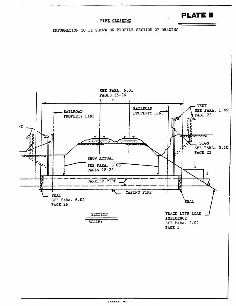
_ ... _ .. _-_. __ ._ ... ---- ...... _----------------------PLATE II
PIPE CROSSING
INFORMATION TO BE SHOWN ON PROFILE SECTION OF DRAWING
SEE PARA. 6.01 PAGES 25-26
?
RAILROAD PROPERTY LI J..-- RAILROAD I PROPERTY LINE
SHOW ACTUAL
SEE PARA. 6:i.0)!5'----_J PAGES 28-29
-----CAiiIERPffi -y---------------~-----
SEAL SEE PARA. 6.02 PAGE 26
CASING PIPE
SECTION
SCALE:
... nftDnO ...,,c1
2
TRACK LIVE LOAD INFLUENCE SEE PARA. 2.02 PAGE 5
5.09
5.10

_ BAD.R.OAD PROPERTY LINE
I
PLATE III
LONGITUDINAL OCCUPANCY
SEE PARA. I PAGE 15
4.02(E) I I
'I L RA.ILROAD PROPERTY LINE
R. R. DUCT LINE --+---.l::J EE PARA. 6.09
PAGES 28-29
TB.i.CK l.IVE LOAD INFLUENCE SEE PARA. 2.02(E) PAGE 5
PROFII.E OF GROUND ALONG CENtERLINE
2
1
____ Jl-=:===:::I~~~~~~~~;;~;~OF~P~I~PE~:3F=~~----+_------------ 130 -1l.Q...
4+00 3+50 3+00 2+50 2+00
STATIONING
PROFIl.E - SEE PARA. 2.02 PAGES 5-7
SCALE - BOR: VER.:
-.A nnROR _ ?/;.?
1+50

PLATE IV PIPE CROSSING DATA SHEET
In acldjtion to plan and profile of crcssing. dmwings submitted for the Rail%cad Compauy(s) approval shall contain the following infOftDation:
Contents To Be Handled
Normal Opercuing Pressure
Normal Size of Pipe
0.5. Diameter
LS. Diameter
Weigbt Per Foot
~ofMan~
iradc or Oass
)pc of Joint
yPe of Coating
oetails of Cathodic PmtectioD.
etaiJs of Seal or Protecticm at Ends of Casing
:ethod of Installation
l8%aCtCr of Subsmface Material At the Cmssing Location
'Proximate Ground Water Level
urcc of InfonnatiOD on Subsurface conditions (Test Pits, Borings or Other)
Pipe Date
CanierPipe Casing Pipe
)TE: Any soil investigation made on MBTA Railroad Property or adjacent to ttacks sball be carried on under the supervision of the Railroad Company(s).
A00898 -263

PLATE
TABLE OF MINIMUM WALL THICKNESS FOR STEEL CASING PIPE (FOR INFORMATION ONLY)
PROTECTED WALL THICKNESS
I:::·:·" .': ':::
:::~PIPE':,SIZE:,.,:,:.···.·,,:::::? · .j·,.!~·\V~~~:g~~~~:I':~'~i' "JitiJCHESY',:.·;::<,:}?
10 0.375 12 0.375 14 0.375 16 I 0.375 18 i 0.375 I 20 I 0.375 22 0.375 24 0.375 26 0.375 28 0.406 30 0.469 32 . 0.501 34 0.532 36 0.532 38 0.569 40 0.569 42 0.569 44 0.594 46 0.688 48 0.688 50 0.688 52 0.813 54 0.813 56 0.876 58 0.876 60 0.876 62 0.876 64 0.876 66 0.876 68 0.876 70 I 0.906
NOTE: FOR UNPROTECTED PIPE 26- AND UNDER ADD 0.032- TO PROTECTED WALL THICKNESS. FOR UNPROTECTED PIPE 28- AND OVER ADD 0.063- TO PROTECTED WALL THICKNESS.
A0089~ -264

MASSACHUSETTS BAY TRANSPORTATION AUTHORITY
RAILROAD OPERATIONS DIRECTORATE
v SPECIFICATIONS FOR WIRE. CONDUIT
AND CABLE OCCUPATIONS
MAY 1994
AOO898 -265

SECI10N 1. SCOPE
1.01 These specifications apply to the design of electric transmission wires and cables (power and communication) which are to be located over, under, across or upon property, facilities, and tracks owned by the MBT A
SECI10N 2. LICENSE TO ENTER MBTA RAILROAD PROPERTY
2.01 Individuals, corporations, or municipalities desiring wire or cable occupations must agree, upon approval of the construction details by the Chief Engineering Officer, to execute an appropriate occupational agreement and pay any required fees and/or rentals outlined therein.
2.02 Application for an occupancy shall be submitted in writing to:
Director of Real Estate MBTA, 10 Park Plaza Boston, Massachusetts 02116
See "Guidelines and Procedures for Construction on MBTA Railroad Property."
2.03 All applications shall be accompanied with six (6) copies of all construction plans, specifications and computations concerning the proposed occupancy.
SECI10N 3. APPROVAL OF PLANS
3.01 Entry upon MBTA Railroad Property for the purpose of conducting surveys, field inspections, obtaining soil information, or any other purpose associated with the design and engineering of the proposed occupancy, will be permitted only with a proper entry permit prepared by the MBT A Real Estate Department. The issuance of such a permit does not constitute authority to proceed with the actual construction. Construction cannot begin until the proper insurance certificate is received and a formal agreement is executed by the MBT A and permission is received by the Railroad Company(s).
3.02 Plans shall be drawn to scale and show the following: (See attached plates I - VI).
A. Plan view of crossing or occupation in relation to all Railroad Company(s) facilities. (See Plate I)
B. Location of wire or cable (in feet) from nearest railroad mile post,
A00898 -266
center line of a railroad bridge (giving bridge number), or center line of a passenger station. In all cases, the name of the County and City or Town in which the proposed facilities are located must be shown.
C. Profile of ground on center line of pole or tower line, showing clearances between top of rail and bottom of sag, as well as clearances from bottom wire or cable to top wire or cable of the MBTA's transmission, signal and communication lines and catenary. If none of these facilities are in existence at the point of crossing, the plan should so indicate. Actual under-clearances are to be shown. (See Plate V for the required clearances).
D. Show all known property lines. If wires, cables or conduits are within public highway limits, such limits should be clearly indicated with dimensions from center line.
E. The plan must be specific as to:
NOTE:
1. Base diameter, height, class and bury of poles. Poles shall be set no closer than 13'6" from face of pole to center line of nearest track. When necessary, however, each location will be analyzed to consider speed, traffic, access, etc.
2. Number, size and material of power wires, as well as number of pairs in communication cables.
3. Nominal voltage of line, type of current and frequency.
4. Number, location, size and material of anchors and all guying for poles and arms.
Double cross-arms are required on poles adjacent to track. AIly tower designs must be accompanied by engineering computations and data.
A00898 -267

SEcnON 4. CONSTRUCTION REQUIREMENTS
4.01 Power and communication lines shall be constructed in accordance with "Safety Rules for the Installation and Maintenance of Electric Supply and Communication lines, National Electrical Safety Code Handbook, Part 2" (current issue), with the following exceptions:
A Item 3 (c), page 2.
B. Casing pipes to contain power or communication wires or cables having an outside diameter of over four (4) inches shall be constructed in accordance with the current issue of MBTA Railroad Operations "Pipeline Occupancy Specifications".
SEcnON 5. LONGITIJDINAL OCCUPA nONS
5.01 Wires and cables running longitudinally along railroad right-of-way shall be constructed as close to MBT A property lines as possible in accordance with Plate m. For electrical power lines and cables with voltages of 34,500 or over and communication cables containing over 180 pairs, the following information must be submitted in addition to the detail of the pole top configuration as called for on Plate IV of these specifications:
A Voltage of circuit(s) or number of pairs. B. Phase of electrical circuit(s). C. Number of electrical circuits. D. Size (A WG or CM) and material of wires and cables.
5.02 Any facilities overhanging MBT A Railroad Property must have approval of the MBT A and appropriate rental charges will be applied.
SEcnON 6. INDUCTIVE INTERFERENCE
6.01 On agreements covering longitudinal occupations, provisions will be included that the applicant will provide appropriate remedies, at his own expense, to correct any inductive interference with MBT A facilities.
AOO898-268

VOLTAGE
0-750 750 - 15,000
15,000 - 50,000 69,000
115,000 138,000 345,000 500,000 745,000 765,000
Other than power lines
OVERHEAD CLEARANCE (Top of Rail to Bottom of Sag)
27'0" 28'0" 30'0" 30'8" 32'2" 33'0" 39'10" 45'0" 53'2" 53'10" 27'0"
At 1200 Ambient
Temperature
(Calculation is 30'0" + 0.4" per 1,000 volts over 50,000 volts)
A00898 -269
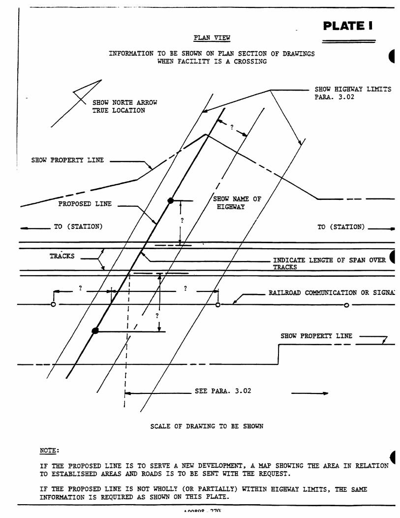
-------- .-. -_ ..... _ .. _---------------------------
PLAN VIEW
INFORMATION TO BE SHOWN ON PLAN SECTION OF DRAWINGS WHEN FACILITY IS A CROSSING
SHOW NORTH ARROW TRUE LOCATION
SHOW PROPERTY LINE
----~ROPOSED LINE
.. ____ TO (STATION)
PLATE I
SHOll BIGmlAY LIMITS PARA. 3.02
TO (STATION) __ ••
. TRACKS ---+------+--__ INDICATE lENGTH OF SPAN OVER 4
TRACKS
? ? r -+-.... ttI-...... --+fo-- RAILROAD COMMUNICATION OR SIGN..-\:
------O----~~~~~--_r_+--------~~-~~~------------------~O------
SHOll PROPERTY LINE I
,.... __ --1-______ SEE PARA. 3.02
SCALE OF DRAWING TO BE SHOWN
NOTE:
IF THE PROPOSED LINE IS TO SERVE A NEW DEVElOPMENT, A MAP SHOWING '!'HE AREA IN RELATION 4 TO ESTABLISHED AREAS AND ROADS IS TO BE SENT WITH THE REQUEST.
IF THE PROPOSED LINE IS NOT WOLLY (OR PARTIALLY) WITHIN HIGmlAY LIMITS, THE SAME INFORMATION IS REQUIRED AS SHOWN ON THIS PLATE.
A nnODO _ ,,)'7n:

PROFILE VIEW
INFORMATION TO BE SHOWN ON PROFILE SECTION OF DRAWINGS - IN CASES OF CROSSINGS
.--__ PROPERTY LINE PROERTY LINE
PLATE II
SHOW NUMBER OF WIRES IN PROPER PROSPECTIVE, VOLTAGE, POWER, GROUND, AND NEUTRAI.WIRES, ETC.
BOTTOM OF SAG, 60 0 r SEE NOTE
? SEE PARA. 3.02(C)
1
-l~1. l?~
~ ~ SEE PARA. 0 0 3.02(C) ~ ~ e- e- ? f:.. ""' 0 0
fzJ r..l z; z; 1-1 ..... TOP OF ...:l ...:l
~J c::: HIGHEST ~I RAIL
fzJl ~, 0 0
I r RAILROAD POLE LINE
*AS MEASURED AT RIGBl' ANGLES TO TRACK
SECTION LOOKING
SCALE: H
V
(DIRECTION)
c::=:t:;:=!:l~ ~ LENG'IE OF X ARM
~ POLE TOP CONFIGURATION TO BE SHOWN
NOTE:
ALL TRANSMISSION, SIGNAL, COMMUNICATION LINES, AND THIRD RAIL SHOULD BE INDICATED AND PROPER CLEARANCES SHOWN.
SHOW MAXIMUM SAG INCREASE OF POWER WIRES OVER TRACKS IF SPAN EXCEEDS 175 FEET IN LENGTH.

PROFILE VIEW
INFORMATION TO BE SHOWN ON PROFILE SECTION OF DRAWINGS IN CASES OF LONGITUDINAL OCCUPATIONS
__ POLE NUMBERS
PLATE III
APPAREN'l' SAG AT 65° F
?
ELEVATION ~ DISTANCE BETWEEN POLES TO BE SHOWN
LENGTH OF ? CROSS AiMS ----
POLE TOP CONFIGURATION TO BE SHOWN SIMILAR TO SAMPLES ABOVE
NOTE: IF POWER LINE CROSSES ~"Y TRACK, THEN INFORMATION SHOW ON PLATE II IS ALSO REQUIRED.
A nnvov _ ".,,,
f., r

• OR BRIDGE PIER OR ABU'l'MENT, RE!.AINING WALLS AND 0 OBSTRUCTIONS INCLUDING TEMPORAR
I BARRICADES FOR CONSTRUCTION, ETC.
HIGH OR LOW
STANDARD SIDE CLEARANCES - TANGENT TRACK
(FOR OBSTRUCTIONS OTHER THAN PASSENGER STATIONS)
C
A D
i •
B
E
PLATE IV
'l'El.EPBONE , ELECTRICAL
I SIGNAL I COMMUNICA
TIONS POLE LINES
FLANGER MARKER, SLOW BOARD WHISTLE POST I
ETC. SWITCH STAND OR ~ ELECTRIC SWITCH _""1-_ ...
MILE POST OR J KILOMEl'ER POST I LOCK 1:~ c=~-:.t-:..-:..~~---
_ 10'-0" j 1IIIIIIIlIJIIINTENANCE RD. NOTE: FOR MAINTENANCE ROAD SECTION DIMENSIONS (A) & (C) TO BE
INCREASED ACCORDINGLY - DIMENSIONS (D) & (E) MAY BE REDUCED TO 8' -6" CLEARANCE.
(WHERE PRACTICAL)
DIMENSION
A
B
C
D
E
• F
DESCRIPTION
GENERAL MINIMUM SIDE CLEARANCE OVERHEAD BRIDGE PIERS 6: ABtJ"l'MEl.'1', RETAINING WALLS 6: OTHER EXISTING STRUCTURES
LOW SWITCH STANDS (3 '_0" MAX REIGH'l') RIGH SWITCH STANDS (OVER 3' -0" HEIGHT) ELECTRIC SWITCH LOCKS
POLE LINES - 'l'El.EPHONE, ELECTRIC, SIGNAL COMMUNICATIONS (MIN)
CENTERLINE WHISTLE POSTS, FLANGER. MARKERS, SLOW' OR SPEED BOARDS AND Ol'HRE WAYSIDE SIGNS AUTOMATIC HIGHWAY CROSSING PROTECTION (MIN) AUTOMATIC HIGHWAY CROSSING PROTECTION (DESIRED)
MILE POSTS - HORIZONTAL
MILE POSTS - VERTICAL
G DEPRESSION OF MAINTENANCE ROAD
.. .n.n.ono ",..,'"
8'_6" 8'-6"
6'-6" 9'-0" 6'-6"
13'-6"
12'-0"
8'-6" 15'-0"
13'-6"
7'_0"

VOLTAGE
0-750 750 - 15,000
15,000 - 50,000 69,000
115,000 138,000 345,000 500,000 745,000 765,000
Other than power lines . .
PLATE V
OVERHEAD CLEARANCE (Top of Rail to Bottom of Sa~)
27fT 28'0" 30'0" 30'8" 32'2" 33'0" 39'10" 45'0" 53'2" 53'10" 27fT
At 120°F Ambient Temperature
(Calculation is 30'0" + 0.4" per 1,000 volts over 50,000 volts)
AOO898 -274
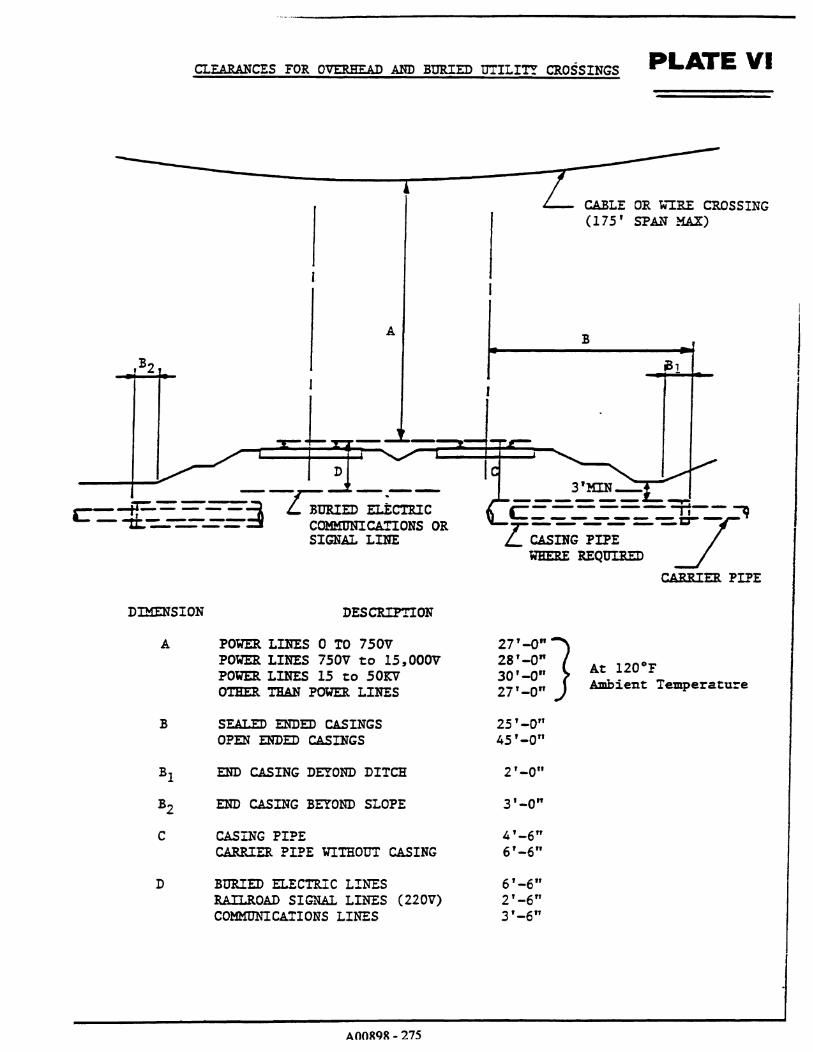
CLEARANCES FOR OVERHEAD AND BURIED UTILITY CROSSINGS PLATE VI
--~~----~--~~~
I L I
A
B2
D
c=~~-=-=~L BURIED ~~~ ~ - - - - :i COMKONICAl'IONS OR
SIGNAL LINE
DIMENSION
A
B
D
DESCRIP'l'ION
POWER LINES 0 TO 750V POWER LINES 750V to 15,OOOV POWER LINES 15 to 50KV OTHER '!BAN Pmm:R LINES
SEALED ENDED CASINGS OPEN ENDED CASINGS
END CASING DEYOND DITCH
END CASING BEYOND SLOPE
CASING PIPE CARRIER PIPE YI'IHOUT CASING
BURIED ELECTR.!C LINES RAILROAD SIGNAl LINES (220V) COMMUNICATIONS LINES
AOOR9R - 275
27'-0" ] 28'-0" 30'-0" 27'-0"
25'-0" 45'-0"
2'_0"
3'-0"
4'-6" 6'-6"
6'-6" 2'-6" 3'-6"
CABLE OR 'W'"IRE CROSSING (175' SP AJ.'l MAX)
At 120°F Ambient Temperature

MASSACHUSETTS BAY TRANSPORTATION AUTHORITY
RAILROAD OPERATIONS DIRECTORATE
VI
BRIDGE ERECTION, DEMOLITION AND HOISTING OPERATIONS
MAY 199~
AOO898-276

Submittals for bridge erection, demolition, or other hoisting operations shall be prepared and stamped by a Registered Professional Engineer and must include the following:
1. Plan view showing locations of crane or cranes, operating radii, with delivery or disposal locations shown.
2 Crane rating sheets showing cranes to be adequate for 150% of the lift. Crane and boom nomenclature is to be indicated.
3. Plans and computations showing weight of picks.
4. Location plan showing obstructions, indicating that the proposed swing is possible.
5. Data sheet listing type and size of slings or other connecting equipmenL Include copies of catalog cuts or information sheets of specialized equipmenL The method of attachment must be detailed on the erection plan. All lifting components must be adequate for 150% of the lift.
6. A complete procedure indicating the order of lifts and any repositioning or rehitching of the crane or cranes.
7. Plans detailing temporary support of any components or intermediate stages.
8. A time schedule (by hour and day) of the various stages, as well as a schedule for the entire lifting procedure.
AOO898 -277

MASSACHUSETTS BAY TRANSPORTATION AUTHORITY
RAILROAD OPERATIONS DIRECTORATE
VII
TEMPORARY SHEETING AND SHORING
MAY 199
A00898 -278

The following items are to be included in the design and construction procedures for all permanent and temporary facilities on, over, under, within or adjacent to MBTA Railroad Property:
1. Footings for all piers, columns, walls or other facilities shall be located and designed so that any temporary sheeting and shoring for support of adjacent track or tracks during construction will not be closer than toe of ballast slope. (See dimensions in the MBTA's Book of Standard Plans, #1000 and #1002 for tangent and curved track). Sheeting will be required when excavation is inside of a line which extends horizontally from 55 feet off center line of adjacent track, then on a 2 (horizontal) to 1 (vertical) slope. This is known as the zone of influence.
2 Where physical condition of design impose insurmountable restrictions requiring the placing of sheeting closer than specified above, the matter must be submitted to the Chief Engineering Officer for approval of any modifications.
3. When support of track or tracks is necessary during construction of above mentioned facilities, interlocking steel sheeting adequately braced and designed to carry E-80 live load plus 50% impact is required. Soldier piles and lagging will be permitted for supporting adjacent track or tracks on Iv when required penetration of steel sheet piling cannot be obtained or when in the opinion of the Chief Engineering Officer, or his authorized representative, steel sheet piling would be impracticable to place.
4. Exploratory trenches, three (3) feet deep and fIfteen (15) inches wide in the form of an liB" with outside dimensions matching the outside of sheeting dimensions are to be hand dug, prior to placing and driving steel sheeting, in areas where railroad underground installations are known to exist. These trenches are for exploratory purposes on1y and are to be backfilled and compacted immediately. This work must be done in the presence of a railroad inspector.
5. Absolute use of track is required while driving sheeting adjacent to any track. Procedure for arranging the use of track shall be through the Railroad Company(s) representative on the project.
6. Cavities adjacent to sheet piling, created by driving of sheet piling, shall be filled with sand and any disturbed ballast must be restored and tamped immediately as required by the Railroad Company(s).
7. Sheet piling shall be cut off at top of tie during construction. After construction and backfilling has been completed, the piling within twelve (12) feet from centerline of track will be cut off 24" below bottom of tie or 24" below finished grade, whichever is greater. Sheeting, used as a form on a permanent structure, will be cut as directed by the Railroad Company(s).
AOO898 -279

8. The excavation adjacent to the track shall be covered and protected by handrails and barricades, warning lights shall be provided by the Contractor as directed by the Railroad Company(s).
9. Graded backfill material shall be compacted at near optimum moisture content, in layers not exceeding 6 inches in compacted thickness, by pneumatic tampers, vibrator compactors, or other approved means to the base of the railroad subgrade. Material in the vicinity of sheet pile shall be compacted to not less than 95 percent of AASHTO T 99, Method C. The Contractor will be required to supply, to the job site, ballast stone as prescribed herein to be installed by the Railroad Company(s).
10. The Contractor is to advise the Railroad Company(s) of the time schedule of each operation and obtain approval of the Railroad Company(s) for all work to be performed adjacent to MBTA tracks so that it may be properly supervised by railroad personnel.
1l. All drawings for temporary sheeting and shoring shall be prepared and stamped by a Registered Professional Engineer and shall be accompanied by complete design computations when submitted for approval.
12 Particular care shall be taken to avoid erosion or filling of the Railroad Company(s) drainage facilities. Erosion and sediment control in the vicinity of the railroad shall be as approved by the Chief Engineering Officer. Correction of disrupted Railroad Company(s) drainage facilities shall be at the Contractor's sole expense.
AOO898-280
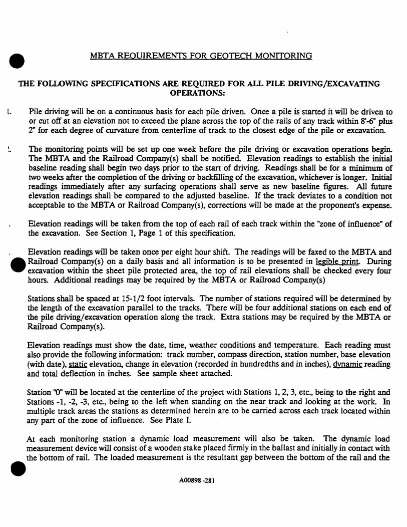
• MBTA REOUIREMENTS FOR GEOTECH MONITORING
DIE FOLLOWING SPECIFICATIONS ARE REQUIRED FOR ALL PILE DRMNG/EXCAVATING OPERATIONS:
L Pile driving will be on a continuous basis for each pile driven. Once a pile is started it will be driven to or cut off at an elevation not to exceed the plane across the top of the rails of any track within 8'-6" plus 2" for each degree of curvature from centerline of track to the closest edge of the pile or excavation.
The monitoring points will be set up one week before the pile driving or excavation operations begin. The MBTA and the Railroad Company(s) shall be notified. Elevation readings to establish the initial baseline reading shall begin two days prior to the stan of driving. Readings shall be for a minimum of two weeks after the completion of the driving or backfilling of the excavation, whichever is longer. Initial readings immediately after any surfacing operations shall serve as new baseline figures. All future elevation readings shall be compared to the adjusted baseline. If the track deviates to a condition not acceptable to the MBTA or Railroad Company(s), corrections will be made at the proponent's expense.
Elevation readings will be taken from the top of each rail of each track within the "zone of influence" of the excavation. See Section 1, Page 1 of this specification.
Elevation readings will be taken once per eight hour shift. The readings will be faxed to the MBTA and
• Railroad Company(s) on a daily basis and all information is to be presented in legible print. During excavation within the sheet pile protected area, the top of rail elevations shall be checked every four hours. Additional readings may be required by the MBTA or Railroad Company(s)
•
Stations shall be spaced at 15-1/2 foot intervals. The numQer of stations required will be determined by the length of the excavation parallel to the tracks. There will be four additional stations on each end of the pile driving/excavation operation along the track. Extra stations may be required by the MBTA or Railroad Company(s).
Elevation readings must show the date, time, weather conditions and temperature. Each reading must also provide the following information: track number, compass direction, station number, base elevation (with date), static elevation, change in elevation (recorded in hundredths and in inches), dvnamic reading and total deflection in inches. See sample sheet attached.
Station "0" will be located at the centerline of the project with Stations 1, 2, 3, etc., being to the right and Stations -1, -2, -3, etc., being to the left when standing on the near track and looking at the work. In multiple track areas the stations as determined herein are to be carried across each track located within any part of the zone of influence. See Plate I.
At each monitoring station a dynamic load measurement will also be taken. The dynamic load measurement device will consist of a wooden stake placed firmly in the ballast and initially in contact with the bottom of rail. The loaded measurement is the resultant gap between the bottom of the rail and the
AOO898-281

top of the stake caused by the deflection of the rail under the load of a passing train. Based on filii observations of the excavation, and at the option of the MBTA or railroad company(s), this requireml may be reduced.
9. Elevation readings taken from the top of rail for static measurement and the dynamic reading shall 1 combined and the sum compared to the adjusted baseline. This reading will demonstrate the differenl in elevation caused by the excavation.
10. The MBTA requires that the track be maintained at all times within established criteria for the specii track classification. At the completion of the project the requirement for tamping and realigning t1 tracks, caused by the settlement from the construction activity, remains with the proponent for t1 duration as specified by the MBTA in their initial review of the work plans. This tamping and tral realignment will be performed by the MBT A or railroad company(s) at the sole expense of the proponent.
AOO898-282

MASSACHUSETTS BAY TRANSPORTATION AUTHORITY
RAILROAD OPERATIONS DIRECTORATE
VIII
BLASTING SPECIFICATIONS
MAY 1994
AOO898 -283

Blasting on, over, under, within or adjacent to MBTA Railroad Property will be permitted only in special cases where it is demonstrated to the MBT A's Chief Engineering Officer that there is no practicable alternative to perform the work.
In such cases when blasting is permitted, the Contractor must submit a detailed blasting program to the MBTA and Railroad Company(~) for approval prior to the commencement of any work. The blasting program must contain the following information:
a. Site plan with location of nearest MBTA structure. b. Plan of each blast showing hole spacing and delay pattern. c. Diameter and depth of each hole. d. Amount of explosives per hole. e. Total pounds of explosives per day. f. Total amount of explosives per blast. g. Type of non-electric delays to be used. h. Amount of stemming in each hole. 1. Type of explosive to be used. J. Soil and rock profile in blast zone. k. Scaled distance to the nearest MBT A facility. L Type and location of seismograph to be used. m. Size of blasting mats to be used. n. Safety precautions to be followed.
The following general requirements are to be adhered to:
a. Obtain the services of a qualified vibration and blasting consultant to monitor the blasting.
b. Use a non-electric detonation system whenever possible. If electric caps are used, a check must be made for stray currents, induced current and radio frequency energy to insure that this hazardous extraneous electricity is at an acceptable safe level.
c. Provide an open face for maximum relief of burden. d. Limit the maximum peak particle velocity to 1 inch per second. Depending
on existing conditions, this may be modified to 2 inches per second. e. Maintain an initial scale distance of 60 ft. per 1-1/21bs. After initial blasting,
scale distance may be modified to a minimum of 50 ft. per 1-1/2 lbs. if conditions permit.
Scale distance = Distance from blast to structure (in feet)
\/Wei2ht of explosives per delay (in pounds)
The contractor shall provide for a pre-blast and post-blast survey, including photographs. An inspection of all nearby MBT A facilities shall be made to determine any changes that may occur due to blasting operations.
A00898 -284

The contractor shall coordinate all blasting with the MBTA and Railroad Company( s) in advance to determine when the charges may be set. The contractor is advised that the MBTA and Railroad Company(s) use two-way radios for train control. The radios operate in the 160 Mhz area. These radios cannot be turned off at any time.
A00898 -285
MASSACHUSETTS BAY TRANSPORTATION AUTHORITY
RAILROAD OPERATIONS DIRECTORATE
IX
TEMPORARY PROTECTION SHIELDS FOR DEMOLITION AND CONSTRUCTION
A00898 -286

The Railroad Company( s) will determine when and where protection shields are required. The design and construction of temporary protection shields must adhere to the following specifications:
1. The construction of temporary protection shields will be designed to prevent any dust, debris, concrete, formwork, paint, or tools from falling on MBTA Railroad Property below.
2. The temporary protection shields shall be erected prior to the start of work. The Railroad Company(s) will determine whether or not sufficient protection has been provided to perform the work over any particular area.
3. The temporary protection shields shall remain in place until all work over the railroad has been completed and shall be removed only when ordered by the Railroad Company(s).
4. To minimize the inconvenience to the users of any properties below and adjacent to the project, the Contractor will be required to complete the actual erection and removal of the temporary shields within time limits acceptable to the Railroad Company(s).
5. The erected temporary protection shields shall not infringe on any existing minimum vertical clearance.
6. The Contractor will be required to obtain the approval of the Railroad Company(s) before commencing any work beneath the shield. In certain areas, depending on the nature of the work, the Railroad Company(s) may require a specific method of protection. .
7. The horizontal shield shall be designed to carry a live load of 100 pounds per square foot and a single concentrated load of 2,000 pounds located to produce maximum stress. The vertical shield shall be designed to carry a wind load of 30 pounds per square foot.
8. Prior to the start of construction, the Contractor will be required to submit the details of the temporary protection shield to the Railroad Company(s), who will review and approve the details only as to the methods of erection and as to whether or not the proposed installation will provide the level of protection required at the various locations. It is the Contractor's responsibility to design these protections so that they are in conformance with all existing laws, regulations and specifications that govern this type of work. Shield plans must include a material list and shall be designed by a Registered Professional Engineer. The drawings and calculations must bear his seal when they are submitted to the Railroad Company(s).
9. If during the actual construction, the Railroad Company(s) deems that the
A00898 -287

shield is not providing the desired level of protection or that the Contractor has failed to properly maintain the shield, all work at the affected location shall cease until corrective measures acceptable to the Railroad Company(s) are instituted.
10. All temporary shields will be constructed using new material.
AOO898-288

MASSACHUSETTS BAY TRANSPORTATION AUTHORITY
RAILROAD OPERATIONS DIRECTORATE
x INDUSTRIAL SIDE TRACK
SPECIFICATIONS
A00898 -289
MAY 1994

SECI'ION 1. GENERAL
1.01 All railroad track construction shall be performed under competent supervision of personnel experienced in railroad construction and shall conform to the standards of the MBTA The MBTA and Railroad Company(s) will inspect and approve all side tracks prior to being put in service. This specification will be used for side tracks directly on or within 15 feet of the MBTA property line. Any construction outside of the MBTA property line will be in compliance with the standards of the serving freight railroad.
SECI'ION 2. MATERIAlS
2.01 MAlERIAL
2.02 RAIL
Rails, ties, switches, frogs, etc. will conform with the standards of the MBTA for various types of turnouts and track installations thereby insuring replacement availability.
The rails shall be 100# ASCE Section or of a heavier rail section in common use, new or relay. Relay rails shall not have more than 1/4" top wear measured vertically along center line of rail, and not more than 3/8" side wear measured horizontally 3/4" below the normal top of rail. Rails shall be free from kinks, excessive rust and excessive head flow. Rails having line or surface bends that cannot be spiked will be rejected. Rail shall be free of internal defects. Rail used on the limits of MBTA Railroad Property shall be equal in weight and in section to the attached main line.
2.03 CROSS TIES
Cross ties shall conform to MBT A specifications, minimum size will be 7" x 8" x 8'6" and shall be treated with creosote in accordance with MBTA specifications. Relay ties may be approved after inspection by the MBTA and Railroad Company(s) prior to installation.
2.04 SWITCH TIMBER
Switch timber shall be new hardwood and conform to MBTA specifications 7" x 9" and of lengths required by MBTA standard turnout bill of materials. All timber shall be creosote treated as specified for cross ties. Relay timber
AOO898 - 2"9t>

as above.
2.05 TIE PIA 1ES
Tie plates shall be new or relay at least 7-1/2" x 10-3/4", 1/2" thick, double shoulder and should be canted. TIe plates must conform to MBTA specifications. Damaged plates or plates showing more than 25% reduction in section due to corrosion or wear will be rejected.
2.06 JOINT BARS
Joint bars shalJ be new or relay, 100% toeless, 24" long or equal and conform to MBTA specifications. Relay bars must be free from appreciable wear. Joint bars shall have a minimum of four hoJes and the holes are to fit the punchings of the rail. Holes to have a clearance of 1/16". Joint bars that cannot be drawn up to give a tight fit will be rejected. No fewer than 4 bolts per joint will be allowed.
2.07 BOLTS, NUTS AND WASHERS
Bolts and nuts shall be new and of a size to fit the rail punchings. They shall conform to AREA specifications for Jow carbon steel track bolts and nuts. Washers shalJ be new spring type of appropriate size and shall conform to MBTA specifications.
2.08 TRACK SPIKES
Track spikes shall be 6" long, 5/8" square with an oval head and conform to MBT A specifications for soft steel track spikes. Tangent track will have at least 2 rail holding spikes per tie plate and all curves over 3° will have 3 spikes per tie plate.
2.09 BALLAST
Ballast shall conform to MBT A Material Specification 9248.
AOO898 - 291'

2.10 BUMPING POSTS
Bumping posts will be Hayes type, Durable "0" or equal, unless otherwise specified, and will conform to MBTA Material Specification 9206.
2.11 DERAIL
Type and quality of derail will be specified for each individual side track requirement. Derail will be connected into the railroad signal system. This will be performed by the Railroad Company(s) at the Owner's expense. Two pairs of insulated joints will be installed at a location to be determined by the MBTA Side tracks with a descending grade toward the main track will require a split switch type derail.
SECI10N 3. INSTALLA nON
3.01 The track will be properly installed with a standard gauge of 4'8-1/2" except on sharp curves. In cases of sharp curves, gauge will be specified by the MBTA or the Railroad Company(s).
3.02 Ballast will be installed on top of subgrade for a depth of at least 6" below the bottom of tie and brought up to the top of the tie at the center and slope off to 1" below top of tie at the ends. It will then extend l' beyond the end of the tie at that height, at which point it will slope off at a rate of 2: 1 to the subballast.
3.03 Cross ties will be placed not more than 24" on center on tangent track and 191/2" on center on curved track. When relay rails are used the unworn side will tie placed on the gauge side. Tie plates will be installed on each cross tie. The center of the joint should be installed so as to be suspended by two ties.
3.04 It will be the responsibility of the builder of that portion of track designated as "property line to end" to connect to that ponion of track designated as "clearance to property line" and provide the necessary joints or compromise joints with bolts as the weights of rail would dictate.
AOO898-292

SECTION 4. BONDING
4.01 Where track bonding is necessary, it will be performed by the Railroad Company(s) in accordance with MBTA standards.
SECTION 5. APPROVAL
5.01 Plans for track installation must be approved by the MBTA and Railroad Company(s) before the design of the facility to receive rail service is finalized.
SECTION 6. CURVATURE OF TRACK
6.01 The recommended curvature shall be exceed 8° or less. The maximum. allowable degree of curve is not to exceed 12° 30', unless approved by the Chief Engineering Officer.
SECTION 7. GRADE OF TRACK
7.01 The maximum allowable grade for all tracks shall not exceed 1.5% descending towards mainline or 3% descending from mainline using 100 foot venical curves.
SECTION 8. ELEVATION
8.01 Super elevation shall not exceed 1 inch.
SECTION 9. SUBGRADE
9.01 Subgrade will be prepared to a grade 18" - 20" below the proposed top of rail and shall be of a material that is compacted to 95% and provides for adequate drainage.
AOO898-293

SEcnON 10. ACCEPTANCE
10.01 Before track is placed into service to receive cars, it will be inspected and approved by a qualified track inspector from the MBT A, the Railroad Company, and the freight carrier.
10.02 No exceptions to these specifications are authorized without the written approval of the Chief Engineering Officer.
AOO898-294

MASSACHUSETTS BAY TRANSPORTATION AUTHORITY
RAILROAD OPERATIONS DIRECTORATE
XI
RIGHT OF WAY FENCING SPECIFICATIONS
A00898-29S
MAY 1994

SECTION 1. GENERAL
1.01 DESCRIPTION
This section specifies the furnishing and installing of new Type I galvanized steel or Type n aluminum coated steel chain link fence. Right of way fence will be 6', 8' or 10' as required by site specific conditions.
1.02 SUBMITTALS
Shop Drawings
1. Include cross sectional dimensions of posts, braces, rails, fittings, accessories and gate frames, design of gates, and details of gate hardware.
2. Include a layout drawing showing the spacing of posts and location of all gates, abrupt changes in grade, and all comer, gate, anchor, end and pull posts.
SECI10N 2. PRODUcrs
2.01 MAlERIALS
A General
1. Steel pipe dimensions and weights: ASTM A-53, Schedule 40 (except the hydrostatic testing requirement is waived). Dimensions specified are outside diameter (O.D.).
2. Provide post with accepted semi-steel or pressed steel tops, so designed as to fit securely over post and cany top rail or spring tension wire; the base of post top fitting shall fit over the outside of post and shall exclude moisture from post. All fittings and accessories shall be hot dipped galvanized in accordance with ASTM A-53.
B. Line Post: For all post heights, unless otherwise noted, Schedule 40, 2.375" O.D. pipe weighing 3.65 lbsjft ASTM A-53 with a 2 oz. hot dipped galvanized coating shall be used.
AOO898-296

C. Gate post: Furnish post to support single gate leaf, or one leaf of a double gate installation, for the following gate widths:
Leaf Width up to 6' 6' to 12' 12' to 18' 18' to 32'
Gate Post 2.875" 0.0. 4.000" 0.0. 6.625" 0.0. 8.625" 0.0.
D. End, Comer and Intermediate Posts
Sch.40 5.79Ib/ft 9.11lb/ft 18.97Ib/ft 2855Ib/ft
For all post heights, unless otherwise noted, Schedule 40, 2.875" OD. pipe weighing 5.79 lbs/.ft. ASTM A-53 with a 2 oz. hot dipped galvanized coating shall be used.
E. Top rail and Spring Tension Wire
1. Top Rail
a. Schedule 40, 1.66" 0.0. pipe weighing 2.27Ibs/ft. ASTM A-53 with a 2 oz. hot dipped galvanized coating.
b. Couplings and expansion sleeves: Outside sleeve type, minimum six inches long.
2. Spring tension wire: shall be marcelled (spiralled or crimped) #7 gauge (.177 inches) plus or minus 0.005 inches in diameter. ASTM A-824. 12 oz zinc per sq. ft.
F. Braces and Tension Rods
1. Compression braces: Same type and size as top rail.
2. Tension rods: 3/8" round rods with drop forged turnbuckles or other approved type of adjustment.
G. Fence Fabric
1. Type I galvanized steel ASTM A-392 Class 2 coating 2 oz.
a. Typical-2" diamond mesh 6 gauge (.192") 2 oz.
b. Hot dipped galvanizing after weaving.
AOO898-297

2. Type n aluminum coated steel ASTM A-491 size 2, 3/8" mesh.
3. Selvages: All types
a. Fabric shall be knuckled at both selvages.
b. Fabric over 60 inches high: knuckled at one selvage and twisted and barbed at the other.
H. Fabric Bands, Brace Bands and Stretcher Bars
1. Fabric Bands: 12 gauge pressed steel 7/8 inch wide.
2. Brace Bands: 11 gauge pressed steel 1 inch wide.
3. Stretcher Bars: 3/16" x 3/4" galvanized steel.
I. Tie wire and miscellaneous Items
1. Tie Wire: Galvanized steel 6 gauge (.192") for post and rails.
2. Hog rings: Galvanized steel 6 gauge (.192") for spring tension wire.
3. Rail and Truss Cups: Galvanized semisteel or pressed steel.
J. Barbed Wire and Extension Arms
1. Barbed Wire: ASTM A121, 12-1/2 gauge, 4-point round barbs, Oass 3 coating.
2. Extension Arms: Projecting at an angle of approximately 45 degrees, fitted with clips or other means of attaching three strands of barbed wire, the top outside wire approximately 12 inches from the fence line and the other wires spaced uniformly between the top outside wire and the fence fabric.
K.. Gates
1. General: Furnish gates complete with necessary hinges, latches, and drop bar locking devices; corners shall be welded or fastened and reinforced with suitable fittings.
2. All gates fabricated from 1.90" O.D. Schedule 40 pipe weighing 2.72 lbs/ft with a 2 oz hot dipped galvanized coating.
A00898 -298

L Concrete: Class 2500 psi concrete consisting of aggregate passing the No.8 sieve.
SECTION 3. EXECUTION
3.01 INST All.A nON
A Place terminal post at each end, comer, gate post, pull post (maximum 500'), or any change in grade or direction greater than 30 degrees.
B. Line posts shall be spaced on a maximum of 10 foot centers. In determining the post spacing, measure parallel to slope of finished grade. All posts to be set plumb and in line. Post spacing on radius as follows:
200' - 500' radius 8' O.C. 100' - 200' radius 6' O.c. less than 100' radius 5' O.C.
C. When fencing is installed on the top of concrete structures, use galvanized sleeve and grout posts or install with suitable galvanized flange casing and galvanized anchor bolts. Set all other posts permanently in concrete.
D. Excavate post hole footings at least 12" in diameter for line post and 16" for terminal and gate posts up to 4" 0.0. Larger gate posts require 18" diameter footings. All footings excavated to a . depth of 42" with a minimum post embedment of 36". Crown top of concrete to shed water and allow to cure not less than 72 hours before proceeding with further work on the post.
E. Brace end, comer pull, and gate posts to the nearest line post, with diagonal or horizontal brace rails used as compression chambers, and with truss rods with turnbuckles used as tension members. Brace line posts horizontally and truss in both directions as required, at approved intervals.
F. Install fabric on post side which best secures MBTA's Railroad Property. Pull fabric taut and tie to all line posts, rails, braces and spring tension wire spacing all ties at 12" intervals. Use hook shaped steel ties confined to the diameter of the pipe to which it is attached, clasping pipe and fabric firmly with both ends twisted at least 2 turns.
G. Barbed wire and tension wire must be taut and properly secured with brace bands at each terminal and gate post.
H. Electric Ground: Where a power line carrying more than 600 volts passes
AOO898-299

over fence, install ground rod at the nearest point directly below each point of crossing. Ground all substation fences and gates and perform other electrical grounding as indicated.
3.02 TOUCH-UP AND REPAIR WORK
Remove and replace fencing which is improperly located or is not true to line, grade and plumb within tolerances as indicated.
AOO898 -300

> 8 00 10 00 • w o
" ;; , H
no "NO ;0"1«" "P,n I liZ" '011 U"'INti
rrrtT;.;rj·!.i:'~~~r.::i"· . I ,.' L····::.~··:·:~ ... :::·.····: :.~ , l ,;;:::,:t;:::::)":1:~::';.:;.;::~
r,nll.n WI""'_~~',"',\ "',-, ,-,-,'il~'~1 'I" ,.,.1 ."" i » _. i . ~ _ -r
..... "011
!W1.l61IIS . 1"'1.1. " "'1 " •• LV nllL AI'M Uti, lUI I, CGAn ... I Oil f"III, &LUII."UII CoAfiD nUL, U'II A.", IIZII Me.H, &' IIAl
1"0.' GIIOur
/
COIIID HOlliN IXllf, CoNClIlR 011 SLlI'" 1M (AU IH'''UCE CION: •• '00"" ..
.... 00, " ...
-~
:Ar.":·;-'::'U-- !. .... r, •• "01 · ... " ,.,,'''', .. .. ...,...--1-1"' roll.' 'HUL II ," 01. PI,. 011 Itl 12 II , .. ~ 'II' COLUIIN v.t:IGH.NO 4 .0 LIS A __ --A-fiilG;1 ffiUiijjY' FENCE iiNu-:l
WHIH H.OH SlCUlllfY flHCI •• I
.--1 ' I" i 'liN
"---'('t Ot'·/t
C.OI , .... U .HoIUllo, MOD.n "UII IHo.H ON 'Hit INU' A' 'OLlOW':
. .. I "' AM'C- .. SfI4 ."", .... "1 ...... 'II', IUIII '0"1' f 111.1 .. '1:' ~, .... ~ I
' .. 'IHO 'Din· '''1 r .. , •• , M eUII,IO,a.onDN IIAlL.;Oll 10'" I
.... '."Ul ... '"II .. '"."",
LINE PANEL "IlIACI " ... EL IU .ICLUDI ... AOD.nONM. ,.NIL IlUCID .t leaWH nCI', '"U" 1100 IH
I 0 ""01 Ifl DlIIICj flO" ~ ------- --~-.--
4'·0" ,.OUlftIAHI 0,1~ft,\0:r'::~1 :r:"1 '~:~iu, It 0'· 0"1 ".Y • gAIl
L ~L! !.!: ~I ___ --'
.', • , POST ANCHORID INTO CONCRETE
.cAKTlll'i18 fENCE DETAIL .AftllO W,/I. 10' UII 0" flHClliOGAfU WIIIH I"OteAnD, IHALI. II NIIII n"AHD. 0' _liD Willi .u'POIIno ON UU""LIt ARMt LOCARD olt ALL POUI
GA rE POST SCHEDULE HIIGHf
Of GAil FlIICI ,on,
• .. ' 'I·
GAl\l, .. AlLUnl IftOIt IIIIlve "HCIIO" 1117" . - -- n
GIIOUND
1. T,-
LIHI t'.~ - pon --- JJ -~\..--- I!-· lIl!-· II IO"lO
~ '=e~ __ 1 ~o"IVIAHC_1UIII a \'<;;LIHI l=- J
.:.::a J' - ."' p, on Hon: UIIo" .................. , ea..,... £ , ., a lion t!!J •• 111 •• 1 •• " •• , •••• , C.,.I '''', ....... Oil ....
DRIVE ANCHOR DETAJL IfOil u.wiiH"" 'liicFuHI POSlI ONul
NOTES: I MUIMUM ,,,.aM .n .... u •• JOITII, III .' ro II 10'-0·
• ,. ... fl ........ "'ACINI _ .. lHO 011 co .... 'A"~ I, AU , ......... IIN. III II co .............. ... • 10" HIIH IEW/I", "NCC,11I UIIIID 10K, fOP CIHfU o. rUN
(j) IIA.UClIU.lnll RAILROAD ':,0 3206 lA, ~ T "'.H_lIfAIION OPERATIONS HIf, '" .... (j) '","OfU" ".vl .. ,. I'~ III j yEllCULAI! SWINg._ rHICK AWIIIH"M ALLOY ~~
SIGHS fa II 01010 ..... _.m". .. ~ ."......... . .......... - . ".. ............. "''''' ..... ''·I~":I .. M: W8" ....... " . ,,' ,) Va alUM S.IIS III OCLL:,': :'::IC~~::III, ItDPW O MAHfI.L~LU:I:~ I.. 1"\ .. ,1Ji> ~ I~ CH'U IIIII,""A'IIIIO"(I. CI IlInl ft. ,
.. I." O~. '&, Stl olt 1.1111 flHCl, "ALL 0·11 C I".U"' 0 0"- ALIIM, SHf!J~ '"G'HllA'"' ~"'CIA '~~~~c 1'. I \ lolli, H_" I:~:~: 1111 41"UP' CHAH:~S:O". OIlA~IA '; N I N G S ION S UIlIItL .11 H • '''RlC ' 4 "...... CH'NGIS IN OlftCCI.OH 0\1 '_ Hllng • ue '1G1t MoU 14 ... " •••
CHAIN LINK FENCING 72'; 9'" Gnd "II.GH SECUR'TY"rrPE
2!!!U, ..

MASSACHUSETTS BAY TRANSPORTATION AUTHORITY
RAILROAD OPERATIONS DIRECTORAT
XII
TEST BORING SPECIFICATIONS
MAY
AOO898-302

SECI10N 1. GENERAL
All borings on MBTA Railroad Property are to be performed according to the following requirements:
1.01 Work on MBTA Railroad Property must be performed with a Railroad Company(s) inspector and/or flagman present.
1.02 Where access can only be gained by crossing the tracks, a temporary crossing must be used. This crossing shall adhere to the following:
A. The location and material must ·be approved in advance by the Chief Engineering Officer or Railroad Company(s).
B. The crossing will be constructed by Railroad Company(s) forces at the Contractor's expense.
C. The crossing must be protected at all ~mes when not in use. Access will be prohibited through the use of right--of-way gates which will be constructed by Railroad Company(s) forces at the contractor's expense.
D. No crossing of the track shall be made without a railroad flagman and/or inspector present.
E. The crossing of tracks shall be kept to a minimum.
1.03 Boring locations, including positioning of the boring rig, shall be kept at least 8'6" from the center line of track.
1.04 All borings must be cased to insure adequate return (of mud and water) and to avoid undermining of the track.
1.05 All holes shall be backfilled with cement grout to fill the voids and protect against an artesian condition.
1.06 The location of all utilities owned or private, shall be located and suitably marked by the Railroad Company(s) and/or the private owner at the Contractor's expense to avoid damage to the utility and/or track structure.
1.07 Prior to entry upon the MBTA Railroad Property, all necessary contracts, insurance
AOO898 - 303

policies and financial obligations shall be provided in a fonn acceptable to the Railroad Company(s).
1.08 Work within the operating right-of-way that has potential to foul the tracks, shall be restricted to periods of non-peak passenger operations.
1.09 While performing the work, full cooperation with the inspector and flagman is essential. The work will be terminated immediately if the safety of rail traffic and personnel is jeopardized in any way.
SEcnON 2. JESTING
2.01 Soil borings shall be in accordance with the current issue of the American Railway Engineering Association Specifications, Chapter 1, Part 1, "Specifications for Test Borings". Soils shall be investigated by the split-spoon and/or thin-walled tube method and rock shall be investigated by the Coring method specified therein.
202 Soil boring logs shall clearly indicate all of the following:
1. Boring number as shown on boring location plan. 2. Elevation of ground at boring. 3. Description or soil classification of soils and rock encountered. 4. Elevations or depth from surface for each change in strata. 5. Identification of where samples were taken and percentage of recovery. 6. Location of ground water at time of sampling and, if available,
subsequent readings. 7. Natural dry density in lbs./sq. ft. for all strata. 8. Unconfined compressive strength in tons/sq. ft. for all strata. 9. Water content (percent). Liquid limit (percent) and plastic limit
(percent). 10. Standard penetration in blows/ft.
2.03 Soil boring logs shall be accompanied by a plan drawn to scale showing location of borings in relation to the tracks, the elevation of ground surface at each boring, and the elevation of the top of rail of the tracks.
2.04 Soil investigation by auger, wash, or rotary drilling methods are not acceptable.
205 Borings shall be taken no more than two (2) feet from the field stake which marks
AOO898-304

the boring location. The stake should not be disturbed during boring operations. Lost stakes shall be reinstalled.
2.06 Unless a boring hole is actively being worked, it shall be securely covered or otherwise protected until permanently filled. When work at each boring hole is completed, the hole shall be properly filled.
2.07 Access to the boring locations must be approved by the Railroad Company(s). When possible, access shall be from public roads. Licenses for Entry, Insurance and Flag Protection must be obtained by the Contractor in accordance with all applicable MBT A Specifications.
2.08 Boring operations shall be confined to each boring location to the extent possible. The contractor shall take necessary precautions to prevent damage to structures and facilities. The site shall be restored to a condition satisfactory to the Railroad Company( s).
A00898 -305

MASSACHUSETTS BAY TRANSPORTATION AUTHORITY
RAILROAD OPERATIONS DIRECTORATE
XIII
FIBER OPTIC CABLE SPECIFICATIONS4
AOO898 -306

SEcnON 1. GENERAL
1.01 The purpose of the following standards is to provide basic information about the MBTA's requirements with respect to the design and construction of fiber optic cables on MBTA Railroad Property to fiber optic cable companies and their contractors.
1.02 All work performed on or affecting MBTA Railroad Property must be designed and constructed in accordance with the Commuter Rail Design Standards (Vol. I and n), MBT A Book of Standards, Railroad Operations Specifications and the following standards. Additional job specific requirements will be contained in the MBTA's Fiber Optic License Agreement and can be obtained by contacting:
Director of Real Estate Ten Park Plaza Boston, MA 02116
The Chief Engineering Officer or his designated representative will be responsible for the approval of all work. No modifications, changes or deletions will be made without his approval.
SECTION 2. PROJECT REVIEW AND COORDINATION
2.01 All plans and specifications shall be reviewed and approved by the MBTA and Railroad Company(s) prior to construction. The MBTA must approve the construction schedule and sufficient Railroad Company(s) personnel must be available before work begins.
2.02 If another fiber optic cable company has previous or exclusive rights along the proposed route, the alignment and cable location must be approved in accordance with existing agreements.
2.03 The fiber optic cable companies must coordinate the construction with others to minimize the disruptions to the MBTA railroad operations.
SECTION 3. CONDVer OF WORK
3.01 In order to minimize the manpower requirements of the Railroad Company(s)
A00898 -307

and afford better control, supervision, and protection, the contractor will conduct his work sequentially and minimize the number of crews and their proximity. Crews should be confined geographically to an area that can be covered easily by a minimum number of Railroad Company(s) personnel. This can be accomplished by a block method of construction. A construction block will be used and is a 1-4 mile segment of right of way in which up to 3 fiber optic cable installation crews can work. The crews can work within the construction block, but cannot work outside of it. The construction block must move as a unit along the right of way. The crews cannot work two blocks concurrently.
SECITON 4. CONSTRUCTION SCHEDULE
4.01 The fiber optic company or its contractor will submit a schedule of work to the MBT A for approval. The schedule will be based on methods of construction acceptable to the MBTA and Railroad Company(s). No work shall begin prior to approval by the MBT A.
4.02 Any changes or modifications to the schedule proposed by the fiber optic company or its contractor must be submitted to and approved by the MBTA prior to implementation. The MBTA, however, may be required to change or modify the construction schedule on account of its operations, maintenance requirements, or manpower shortages. In this event, the MBTA will give the fiber optic cable company as much advance notice as possible.
4.03 Construction schedules will be reviewed and updated every two (2) weeks or as required.
SECITON 5. ESTIMATE OF EXPENSES
5.01 An estimate of anticipated expenses will be provided based on durations provided by the fiber optic cable company or his contractor and construction schedules approved by the Railroad Company(s). Any changes in the schedule will cause the estimate to be revised. The fiber optic cable company or his contractor will be responsible for all of the costs incurred by the MBTA and Railroad Company(s) in support of the construction activities. This includes design review, engineering support, administration and supervision.
A00898 -308

SECllON 6. BILLING
6.01 The fiber optic cable company or its contractor will be required to pay for railroad protective services in advance of costs incurred.
AOO898·309
PROPOSAL
B00420 - 311

Commonwealth of Massachusetts
Project No. 046450
MassachUsetts Highway Department
Page 312
THIS PAGE INTENTIONALLY LEFT BLANK
A00898 - 312

Commonwealth of Massachusetts Massachusetts Highway Department
Project No. 046450 Page 313
DOCUMENT B00420
PROPOSAL
For Bridge Replacement (Structural Steel) - Middleboro A venue over Conrail
COMMONWEALTH OF MASSACHUSETTS
LOCATION.
The work referred to herein is in the City of Taunton, MHD District DISTRICT 5, County of Bristol, Commonwealth of Massachusetts, and is shown by a set of plans and profiles, on file in the office of the Highway Department and extends as follows:
Begining on Middleboro Avenue east of Br. No. T-I-3 at Sta. 19+70 thence continuing westerly to Sta 34+00, for a distance of 1430 feet. Also the project includes work on a portion of Richmond Street starting at the intersection with Middleboro A venue thence continuing 600 feet northerly.
To the Party of the First Part:
The undersigned, as bidder, certifies that he/she is able to furnish labor that can work in harmony with all other elements of labor employed or to be employed in the work.
The undersigned, as bidder, declares that the only persons or parties interested in this proposal as principals are those named herein; that this proposal is made without collusion with any other person, firm or corporation; that he/she has carefully examined the location of the proposed work, the proposed form of contract, the standard specifications and plans therein referred to and the Special Provisions hereto annexed; and he/she proposes and agrees, if this proposal is accepted, that he/she will contract with the Party of the First Part, in the form of the contract referred to herein and to be annexed hereto, to provide all necessary machinery, tools, apparatus and other means of construction, and to do all the work and furnish all the materials specified in the contract, in the manner and time therein prescribed, and according to the requirements of the Engineer as therein set forth, and that he/she will take in full payment therefor the following unit prices, to wit:
046450 - 97
B00420 - 313

Commonwealth of Massachusetts
Project No. 046450
Massachusetts Highway Department
Page 314
THIS PAGE INTENTIONALLY LEFT BLANK
B00420 - 314

5TAUMAF 2
ITEM ITEM WITH UNIT BID PRICE UNIT PRICE ANOUNT NQ QUANTITY WRITTEN IN WORDS Dolen Cents Dalen C.
: -- . -. -----. I
: 1 1
101. 1.5 CLEARING AND GRUBBING 1 1
Ab~~-1 1 1 1 1
"lSOO:a: 5,OCO:~ PER ACRE 1
1 --'-------- - ------- 1 115.1 1 DEMOLITION OF BRIDGE 1 1
STRUCTURE NO. T-1-3 1 1
~~~P 1 1 1 1
AT~ -- -.;. StqfYirO IOJ ~O 000 PO LUMP SUit
1 I 1 I I -- -- ---- ...... T-
120.1 2,550 UNCLASSIFIED EXCAVATION 1 1 I 1 I 1
Te--. ~~ 1
10 :t'O 1
AT-- - ----- ~----. U;SOo po PER CUBIC YARD I 1
I --- -- --- --' -r--129. 205 BIT. CONCRETE EXCAVATION
1 1 I 1 BY COLD PLANER I 1
AT~----- ~ 1 I
10 PO G.., os-o 10 0 -----PER SQUARE YARD I 1
I 1 ---- - --- -,- ~--140. 720 BRIDGE EXCAVATION I 1
1 I 1
AT~ ~~---I I 1
l~po I 10 fu:J iSJ
PER CUBIC YARD I } 1
----- ----- . ---- --I-- --'--TRENCH EXCAVATION I I
141. 25 CLASS A I I
I I
AT.z;~ ~j()\.:J 1 I
. i ------ S-:OO 12..~:Ou .PER CUBIC YARD I 1
I ----- -- -------- -- --- ---I--I 142. 380 CLASS B TRENCH EXCAVATION I- I
1 ~ 1
ATL~~L~-- I 1
rloo I
"VO~ PER CUSIC YARD 1 I ---- - - ---- --- I ---...,.----
144. 135 . CLASS B ROCK EXClVA TION 1 1 1 1
~~ 1 1
..., 'yt 00 E_bo I
AT-- --- tI-; 7 ZS-:OO ER CU8IC YARD I
I I I I
I CARRIED FORWARD ~l..., Coc9-<) :o?
046450-97 TAUNTO~

]
ITEM NO.
145.
5TAUHAF
QUANTITY
1
3
ITEM WITH UNIT BD PRICE WRITTEN IN WORDS
BROUGHT FORWARD
DRAINAGE STRUCTURE ABANDONED
AT~~0L~-
AMOUNT UNIT PRICE
DoIIc:rs Cents· Dollars C.
I 1 1 1 1 1 1 1 1 1
3 6{) :cso ) co lac EACH 1 . 1
------f------~-------------------------,---t:--~----+-. 1 1 1 1 1 1
r----L~ 1 ~ j--""' 117 (1..9V : ~
150. ORDINARY BORROW
AT~ - ~e~ __ _ PER ClIBIC YARD 1 1
-------+----------r----------------------------~-------~----~------,_-SPECIAL BORROW 1 1 1 1 ;1 1 1
AT~_,_----OC>-__.,7,r.."--~--- UJ ~ I, 00() bo
150.1 50
PER CUBIC YARD 1 : __________ -+-_____________ ~----'J- -,-_
GRAVEL BORROW :: 151. 3.720
n5;&;t-~~ --- J.ro "l.-"I,7bO:&':> PER CUBIC YARD : : ------ ------t-------------.-.-.-------+-.----.-,- -1---
GRAVEL BORROW FOR BRIDGE 1 : 151.1 210 FOUNDATION 01 1 1
AT#~_~_....,o'lg_.V_t0____ Ih :00 5/3 faO ~O PER CUBIC YARD : 1 -----+-,---___ I----------------------t-~------. ..J--.
1 1 15~ • 190 CRUSHED STONE FOR DRAINAGE,
REYET. AND W.W. FOUNDATIONS -r:"./) -I- _ ~ ~
AT-~~----~
PER TON
1 1 1 1 1 1
2.O:oa f. ~ ~ 1 I I
..J I -------~--------.~-------.------------------------~------"---~-----,--I 170. 6,325 FINE GRADING AND COHPACTING
- SUBGRADE ~REAS o.~/) DO &-0
AT...c;;c::\ - --PER S ARE YARD
1- I 1 I I I 1 I
! pO ,h, S Z.S- PU I I
--------+----------------------------------~-----.~~~------~-. INSPECTING & TESTINC; FOR ASS. : : 182.1 100 CONTAINING "ATERIALS : I
AT~_~;/OO__ IS-Po I,SVOro PER LINEAR FOOT -: I
I I
CARRIED FORWARD
046450-97 TAUNTON

ITEM NO.
182.2
QUANTITY
4
ITEM WITH UNT BID PRICE WRITTEN IN WORDS
BROUGHT FORWARD
UNIT PRICE AMOUNT
Dalen Cents· Dolen Cen
: : 100 REMOVAL OF ASBESTOS 1 1
1 1 ~/ 1 1
AT~ ~C~___ l-O:O 0 .z.., 000 :00 PER LINEA~ FOOT 1 . 1
_____ ~-,~ ____ ----~---------.------------~-------~------I~-~--------L--1 1 18ft .1 25 DISPOSAL OF PRODL~S A~ --
TREA.TED WOOD
=4&---,f!9_- . PER TON
1 1 1 1 1 1
/00 roo l-,S"bD~ 1 1 1 1
------~----.----~~------.-------------------~------~~~------,----10 CATCH BASIN 1 1
1 1
ATb;~L ~~~- ~-oioo y.9JQ iOO EACH 1 1
-------,~---------~----------------------------~------~I--~------~---4 CATCH BASIN-SPECIAL (SHALLOW) : :
AT&.....,.,~~qp- 700 too 5/ bOo ~O EACH 1 1
-----+------+--------------------;-,-----::-,-I--~-_f_-1 1 1 1
A) -It- J 1 ~~. ~l.4 : gvo :eo ATN_-_~ I,)oo,"bo q;-I 1
EAC 1 1 I
~-----~-------,~--------------·----------------~·----~t--- - ~---1 1 1 1 1 1 1 1
~/Q:)oIO~ 1...,0'00 pO 1 1 1 I
------~---------~f--------·----------------------~----~'---~------~I~-~ 1 1- 1 I I 1 I
]SD pu 3, ISO Po I I I
------------,------+-------------,----------------~,------~~~-----~--: I I I I 1 I I
3c..Slo_ISQ ~J 'LO~~ I '-f I I
1 I
201.
201.31
202.
203.
221.
222.1
8 MANHOLE
1 MANHOLE-SPECIAL
9 FRAME AND COVER
14 FRAME AND GRATE MHO CASCADE TYPE~~
AT~~~~---EACH
CARRIED FORWARD
046450-Q7 TAUNTON

ITEM NQ
241.12
5TAUKAF
QUANTITY
5
ITEM WITH UNIT BID PRICE WRITTEN IN WORDS
BROUGHT FORWARD
760 12 IN. REINFORCED CONe. PIPE
-d '--I:-.. 6v -7.t-V AT.L~+---- -----
U~ PRICE AMOUNT
Dalen Cents Dolen c.,
I I I I I I I I I I
1"Z.. :00 'l.:.If{ 11.0 :<,gJ PER LINEAR FOOT : . I
-----f-.------·...j--~-·----------.. ---.--~I-----r-2 12 IN. REINFORCED CONe. PIPE : I 241.121
FLARED END ':
AT~~P-~- ~-Vf:' 7010 !<so . EACH I :
~---~-.+---------~--------------.-----------.--------~---.~---~------,---I I I I
.....0 I,. A"I I I
AT~----::;:O~---- /fO ~ / tftf O:tX>
241.15 36 15 IN. REINFORCED CONe. PIPE
PER LINEAR FOOT I I : ----.-+----.-....j--.----------.-.--- ------~.---....J~--t----~-
I I 241.151 1 15 IN. REINFORCED CONe. PIPE . FLARED END ~ k .0' .J~ . ..i.t- ~t,O ATA~ -.. ~..1rp9- ~.c __
EAeH
I I I I I I
~.:>?:J :Ot...> tJ.. r:;;o 100 I I I I ---..--+------- ----------,------,------+_----i:--+-------I---: 241.18 95 18 IN. REINFORCED CONe. PIPE
AT klq-~ -~k---PER LINEAR FOOT
I I I
l./-4J I~ I
I I I I
Lf ( I r;;o p.:) I I
-------------------+-·-------·--·-----------·------~·--~I~-~·-------~--I I I I I I
I
Jfr;~ S5DP I
~ ____ ,-I --t---- I -----.-+-----~ -------------~--...,. . -,---
50 STONE FOR PIPE ENDS : _ I I I
AT~-{.~ ~-- z.s-1ov /Jl-5b6J PER SQUARE YARD : :
-------~---------~-------------------------+----~~------~--400 16 IN. DUCTILE IRON MATER : - : PIPE (RUBBER C;ASICETV : I
A ./-dt- !-J-I ~tLt.V___ hTtAJ I ~.~ /I~ 7 - ~/~~
. PER LINEAR FOOT : I I I
241.181
258.
302.1~
1 18 IN. REINFORCED CONe. PIPE FLARED END ~
:r. ~ d t;.~' ~/W aT~"'" :~ ~--" l ("
EACH
CARRIED FORWARD
046450-97 TAUNTON
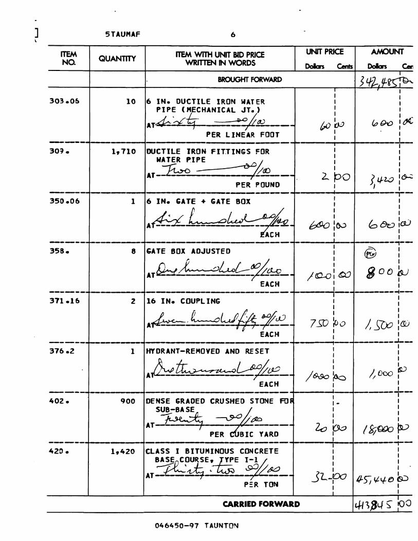
] ~
ITEM NQ
303.06
5TAUf1AF
QUANTITY
10
6
ITEM WITH UNIT BID PRICE WRITTEN IN WORDS
BROUGHT FORWARD
UNIT PRICE
Dabs Cents
AMOUNT
Dabs c:.
: I 1
6 IN. DUCTILE IRON WATER I :
PIPE (~HANICAL JT.) : 1
AT4¢-,:-£~ --=wjr .... tV____ ~~. ~~ l~ PER LINEAR FOOT : 1
-------,~--------~--------------------,--------·-----~'-----·--~I---·~-------~ I 1 30~. 1,710 DUCTILE IRON FITTINGS FOR
MATER PI~~~ AT-~ - .--
PER POUND
I 1 1 1 1 I
I 2.. pO ) I./-ZO I~
1 >J : ~--- -'---------+-------------------+-----11---+----,..-
6 IN. GATE + GATE BOX 1 1 I 1
At.b:L L_-E~_ b!Jo io.:> b 8v :eLI ACH :
350.06 1
------.. ~---------+------,-. --,------+-----...... --If-----,---358. 8 GATE BOX ADJUSTED
AT£!d.J-. - _ 'U--.$-~_ EACH
I I I
800~ I I ------- -----------.-'-----------------------+-'----;1-'-1--------1--
16 IN. COUPLING I 1 I I
Ab ,L ..o~3-_ 7 §J ~o /, SO;; 1(0 371.16 2
EACH I I
------~-------------..... -------,----_--_+_._---tl--f--.----_-J--I I 1 I I I
I kJ / Bc)o ~ It ()OO I
I I ~. ___ J-._ 1 I
DENSE GRADED CRUSHED STONE FO~ I _ I
SUB-BASE ~ I II ~±-v;-o I
AT~ BI::A;;-- 20 ro /f;j{){)o ~
376.2 1 HTDRANT-RE"OYED AND RESET
Ab~~).JE--EACH
402. ~----~--------~---------------------------900
I -~-----+----------~--------------.-----------~-------~~-------~--I I 420. 1,420 CLASS I BITU"INOUS CONCRETE
B~~OURSE'~E ~-1 ~ ' .. .J- .~ ~ M AT- ~.. ---
P:R TON
CARRIED FORWARD
046450-Q7 TAUNTON
I I I I I I
J I I L-po Q..5) c,t If t:> &:> I I I I

ITEM NQ
443.
5TAUMAF
QUANTITY
7
ITEM WITH UNT BID PRICE WRITTEN IN WORDS
BROUGHT FORWARD
UNIT PRICE ANOUNT
DoIcrs Cents· Dollars Cen
I I I I
7 WATER FOR ROADWAY OUST CONTROL I I
AALA- ~~__ ~-v i 6:J ~(J io:J ~ PER 1000 GALS : : ----... -- --------1-------__ . ________ -+-___ .--_ .... ____ ._
19250 CLASS I BITUMINOUS CO~CRETE I I PAVEMENT TYPE I-I ~ : : ~._~ ___ d2P w ") , 110.) I AT~ -- --. ~'- I ~OOOI9,)
460.
PE TON I ': -------t---------------------...---+------11---1-----.-15 8t TUMEN FOR TACK COATI I
I I
~ I I '~/ I I
AT ~-::::. ~~---- s-loo 7S fP
46ft.
PER r;ALLON I I ------f----,----t---------------1----~J-.__If-----_r_-
I I 46".5 3,500 HOT POURED RUBBERIZED ASPHALT SEALER
AT'£#!i- CL-.A; ~ __ _
, PER Ll~~OT
I I I I I I
O~ '11.so~ I I ------.. ~--,-----t----·---------+_----i_-~--------I---I I
I I I I I I I I
~ 116-J «-; 00 C ICV I I
472. 100 BITUMINOUS CONC. FOR PATCHIN;
<t:~- p L- eo:'/ ~ AT---L~-_--.-,.:~-------
P:R TON I
-------+-------~.-------,----------------------~---~---~---~--I I 100 SAWING BITUMINOUS CONCRETE I I
I I
A~:C----- ~p{~- -- Sro 5&0 kv 482.3
PER LINEAR FOOT I : ~---- -----+----------.---.. ---~~---'-_f----,_-
75 GRANITE CURB TYPE VA3-STRAI"'" :. I 503. -L I I
AT-~'--b~ ."'<:H/ j'lY-2 _- I ~ / -- 1'1 FO I, 1/-1.-~ fU PER LINE'AR FOOT I I
I ----------- -----,--------------t-.-u -----,:-....... -----..,...--
I I I I I I I I
""L. '_:W SLS" fP I I I I
503.1 25 GRANITE CURB TYPE VAl-CURVED
A:-twJ:, -~ ~~. PER LINEJ' FOOT
CARRIED FORWARD
046450-97 TAUNTON

] 5TAUl1AF 8
ITEM ITEM WITH lNT BID PRICE UNIT PRICE AMOUNT QUANTITY NO. ~INWORDS DoIIcn Cents ...n...a- C. ,.~~.
BROUGHT FORWARD ~ I
. 4-,(G," L17 \0: do I I I I 511.1 2,775 GRANITE EDGING-TYPE SB I I
-STRAIGHT I I
ATI~ ---.AD /lO I I
·/~rOu tit ~ l,Ji ~ , -------• I PER LINEAR FOOT I I -------I-- --- I --1--
512.1 200 GRANITE EDG I·NG-T.YPE S8 I I
(RA~;dk? DR LE~ I I I I I I ' A~ ~-- ;ra :00 3 l.o-o 10...;
PER LINEAl FOOT . I I I I
...... -----1-- -- - -- I ----.-6.20.1 1,556 ST. B". HNY. GUARD-TYPE 55 I I
I (SINGLE FACED) I
I I
AT-~-: -<SJ-Ob I I
". --- /0:00 I~ 560 p::: PER LINEAR FOOT I I ------1--- - --- .. t ----1---
620.3 50 ST. BM. HNY. GUARD-TYPE 55 I I I I
~ED CURVE~) I I
AT -- - - ~e~ __ I
:00 1/ :00 SSO I PER L tNEAR FOOT
I I ---------------- - - -------, -- -f---
620.4 5 ST. B". HWY. GUARD-TYPE S5 : I I
BURIED ~lD CSIN,GL~ F~CEO) I I I - I
I
ATL~ ~~E- 'I-)v p.? l../~~ EACH I
I I
------ --- - - 'F 1-'----..1-..-. 627.1 1 ST. BM. TERMINAL SEcn ON I I
I I
(SING~ FAC!~dw I I
I I
AT&: ; ._-- /oo:~ /0'0 :tW EACH I I
I- I ------r--- --- - I--I 628.1 2 LEADING END FOR ST. B". HNY. I- I
~8R:~19Q I I I I
AT .:,- -- ~ 7-2; IJ.J I, .)l)o:&J v EACH I I
I I ---- - - --- I -~-.
628.2 2 TRAILING END FOR 5T. 8M. HNY. I I
C;UARD ~E ~<.O I I I I I
I .
7 Sl>_IQ::> h .100 ja:) ~ L!r-- / I E CH I
I I I I
I
CARRIED FORWARD >J,IS-~:~
046450-97 TAUNTON

ITEM NQ
611.
5TAUMAF
QUANTITY
9
ITEM WITH UNT BID PRICE WRITTEN IN WORDS
BROUGHT FORWARD
UNIT PRICE AMOUNT
: : 245 FENCE REMOVED AND STACKED I I
1 1
AT-:£~ ~;/q.e -- r-~D Z r:.9U . ~~ I,l.. ...)'1-PER LINEAR FODT
-------~--------~------------------------------~------I~~-------_t__ 691. 1,750 SEDIMENTATION (SILT) FENCE : 1 1
AJ~ ~;2w . __: : Lf ~O 7 ooo:~
PER LINEAR FODT I I 1
-------~---------+--------------------.-------~.----.~I~-~------~II--35 CONCRETE SIDEWAlK : 1 701.
1 1
AT fL.~_ ~&w - -- J{)~ /'os-pb PER SQUARE YARD ~ J : _______ ,~-------.--~----------------------------~------N-~~------~--1 1 703. 115 BITUMINOUS CONCRETE DRIVEWAY 1
• 1 1
A~ :f~ ~& -- . 7S-~ tl. b2.-.rio PER TON : 1 1
------~----.----~--------------------.. ----------~.------,~---~------'--~--1 1 1 1 I I 1 1
1 2.. 7..0 1"-' 13 1. O~
I I 1
-------+--------~.----------------------------~----~.----~~~-------~--i 1 I I 1 1
I
'lo 0 Ua I, "0-0 :0::> 1 1 1 I
-------+----.----~------------------.------------~.---------+-------,---4 BOUND-REMOVED AND RESET :_ 1
1 1 1 1
/ l,r loo ~() :ro : 1
--------+---------~--'----·-·--------·------------~------~I --'~-------,---4 BOUND-REMOVED AND STACKED : :
"J).:eL-,.~r-- (~-iOo ljfb i~ EACH :. ~ :
710.3
710.4
711.
712.
6 BOUND (LETTERED-GRANITE)
A~f~:eLd_~-----EACH
8 BOUND (PLAIN-GRANITE)
,,-;kd--~.:::..---EACH
CARRIED FORWARD
046450-Q7 TAUNTON

ITEM NO
715.
IiTAtJMAF
QUANnTY
10
rTEM WITH UNT BID PRICE WRITTEN N WORDS
BROUGHT FORWARD
6 RURAL MAIL BOX REMOVEO
AND~~tv· ~T~ - ----
EACH
AMOUNT UNIT PRICE
Dolan Cents DoIars c..
: ~' : I I I I I I I I I I
190:~ (000 ~ I I
--------.~--.----.--~------------------~--~--~.--------~~-------+--12 ~NGINEERS FIElD OFFICE AND : : 740.
EOUI~PE A ~ : : ~.(Q.q; ~~A«J -- I, a:x>¢:b I z../<X:U~
PER MONTH I I
------~~--------~---------------------------~.------.t__,-P------~--I I 900 ~ODIFIED LOAM BORROW I I I I I I
17:00 1S:3 oo:~
751.11
/P .. .,~l~ --,9O!!{;(l W- ---. ,-----
PER CUBI: YARD 171
~----,~---------.~.------.. -------------------------~--------~I--·-r--------t--7,000 IrEHPORARY AND PERHANE'IT I I
I 765.11
~TS~N~____ ) ~O 7/000:,:O~ PER SQUARE YARD I
--------~-------.~---------------------------~,-------+---~--------+--6 ~AY MULCH I I
I I
~ ,L-dd!~ ~~ : : ~T- ----r;~~..!.-- LSD P, /. ~?JO lU
767.
PER. TON I ( :
--------~~--------~-----------------, --------~-_-----.I--.-r--...----_r--I 767.8 500 ~ALES OF HAY FOR EROSION
CONTROL ~TZ.~ ,~b ____ _
/ EACH
I I I
ryo I I I
L so.:' :60 "I I
I I ---------~-- -~--------------------------~-----~I~---·~------~--
PAVEME.NT MILLINGS MULCH UNDER I I I I GUARD RAIL I I
~T b..:ro --~~- 2.. ~ 11../l..:0' PER LINEA~ FOOT I I
-------~--------~-----------------------------~----~--.~----.--_t--200 ~WN SODDING : I
I .
-~ . ..., ~tP "':00 I II~~) .~ ------ { I I 'f- I l1'l""I PFR ~OUA; YARn :. I
769. 1,606
770.
I
CARRIED FORWARD ~, l8 ¥7 : eo

CiTAIIMAF 11
ITEM ITEM WITH UNIT BID PRICE UNIT PRICE AMOUNT NO. QUANTITY WRITTEN N WORDS DoIbs Cents Dolen Can
I
BROUGHT FORWARD ~f6Y:7 :00 I ~I I I I I I
77~.5.37 3 ~APLE-REo-·OCTOBER GLlRY· I I I I
6-BF~ ~ I I I :02 ~T~ ~= .c/.uJ~tQ_ -z..OO~ beo
I EACH I 1 I ---- -- . --- ~-18~.633 16 ~LUEBERRY-HtGHBUSH
I 1 I 1
2-3 FEET ~ I 1
~T~4-~ ~---' I 1 I q-w:o; "}o IOc)
EACH I 1
I --- - - --- .--L __ .
790.119 12 PoGWOOD- SILKY 2-3 FEET I 1 I I
~T~ ~#tU I I I I I
<;(V ~o - /------ I.J-:O~ ) EACH I 1 -------t----------- ~---....-,-- ----- I -1.-.
1 832.1 33 ~ARNtNG-REGULATORY ANO ROUTE I I I MARKER - ALUM. PANEL TY. A 1 I
~T ~ ... ~d!-0 I I
/0 :0 0 3]0 ~o --~-- ---- ---PER SQUARE FOOT I 1
I I ----- -- ----- .-833.1 6 PELINEATION FOR GUARDRAIL I I I
~ I I
~L~--I I I
"T- --- / '2..: 0 0 72- 100 EACH I 1
I ---- ----- -"-- -T-I 847.1 5 SIGN SUP (N/GUIDE)+RTE MKR WI 1 I 1
1 ~~POST ASSEH. -STEEL I
I I I 1
: -..a~~~_ ;-00 ~ In = -- -- /Cb :0.0 EACH 1 I
---- ------~- -+---SAFETY CONTROLS FOR
I-1 851. 1 I I
CDNSTRUC~ERATI~ I
1 1 ~$:'..vt' --.oL-~7~O __ 1 1
StCX>o :QO S BO 0 lL1 ,. 1
LU"P SU" 1 1 --- --- -.L._
SAFETY SIGNING FOR 1 1 852. 201 1 1
CONSTRUCTION OPERA~NS I 1 .
19. I
X~~~~ 1, IO~ ~ ~T -- 1 PFR C:Olf (RF FnnT I 1
CARRIED FORWARD ho~, '9f;\90
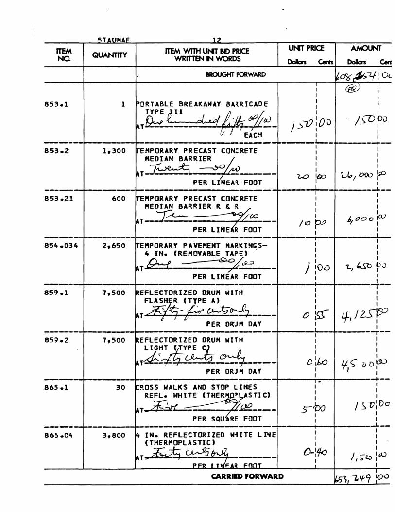
I\TALJMAF 1~
ITEM ITEM WITH UNT BID PRICE UNIT PRICE AMOUNT NQ QUANTITY WRITTEN IN WORDS Dalen Cents Dolen Ceni
BROUGHT FORWARD ,I
~cF6 ,$s,c.r: 0<-1 @) 1
1 I
853.1 1 PORTABLE 8REAKAWAY 8A~RICADE I
TYPE pI t ':J. I
l.)lJ 00 /ropv u~A=:i 14-~~-[I EACH I
I ----~-.---.~---.------- -~---._.-Io_-+----'--T-
TEMPORARY PRECAST CONCRETE : KEDIAN 8ARRI~~/. I
853.2
u ,.~ ~ --- U> ,t¥> u", 000 ~ _______ ~~---__ --~.-------P-E-R--L-IN-E-A-~~~-~----+I--.~---------L--
I I 853.21 600 ~EMPORARY PRECAST CONCRETE
"EDt~RRIER ~aJ ~T-~- lL! __ _
PER LINE R FOOT
I I 1 I I I
I .0 ~ .6, 00 0 :Q.7 1 I _________ ~------·~----·------·--------~----~----~I--·~-------L--1 1 854.034 2,650 ~E"PORARY PAVEMENT "ARKINGS-
4 IN. (REMOVA8LE TAPE)
,.TP:--( ~~----PER LINEAR FOOT
1 1 1 I 1 1
I :Oc:J 'Z..I 'StJ P J 1 I
1 ----I---.---,-~.---- ---- ---~---~"""·------I"'-
REFLECTORIZEO DRUM WITH : I 859.1 FLASHER (TYPE A) I: 2:" ~ ./. A CJ-,1;jft-- a.. 1
~T "'i0 -p= ':---::..;..---- 0 ls:1 l/-, J D-p-=' PER DRUM DAY 1 1
------~~-------I~-------------------------~·------L--~.-------_r--1 85~.2 ~EFLECTORIZEO ORU" WITH 1
~:2t;t;.~ ~- oi~ PER ORJ" DAY : -----__ I--__ . ______ ,~---------- ---------~----~--,~-----P--1-
~ROSS ,WALKS AND STOP LINES 1 REFL. WHITE (THER£~STI C) :
~T~~Q£--- s-bo
865.1 30 1 I 1
19:00 1 1 PER SQUiRE FOOT :
----~---.-------~-.---------------,------------~-------~~-+,-------~---1 1 866.0lt ~ IN. REFLECTORIZED W-fITE L I~E (THERMOPLASTIC)
~T ;£~~-~ ----PFR I "'{FAR FnnT
CARRIED FORWARD
I 1 1 1 •
0-1111-. I
"TV ) --)"'" I tJJ I , !;, o.v 1 I I

ITEM NQ
867.0.4
I5TAUMAF
QUANTITY
4,000
13
ITEM WITH Utfi BID PRICE WRfTl'B'\IIN WORDS
BROUGHT FORWARD
AMOUNT UNIT PRICE
Dollars Cents Dolen Cen
I "t;:'\ 1 I \DII'" 1 I I
Itt IN. REFLECTORIZED YELLOW : I LINE (THERMOPLASTIC) I :
AT I.~ ~dt----- Oktc? ~ ~DO r~ PER LINEAR FOOT 1 I ________ .~----____ ~ ______ ----------------------~------L--~--------~--
2 !sTREET NAME SIGN :: [ J /I 1 I
~X~~~: 4ool~ ~:~ 87ft •
EACH I 1
-------~----------~----------------------------~-------t'--_+--------·--I 1 I 1 1 1 1 1 I II ~ l(.tj rn :00 '-r-::JV 1
87ft .4 9 ~AFFIC SIGN
~ ~T- -._-- o;L~------EACH
REMOVED AND
"":>""", 1 ______ .~_-____ ~-------.----------_+.--------~-.~--_-1-_ I
"'000 PSI, 1.5 IN., 565 CEf1ENr I I CONCRETE MASONRY : I
I\~k_z~' ~L--~d~ ___ ~ (9.9O:G..J J" 00 C :c.t 901. 3
PER CUBIt YARD ': : --------·~---------~----------.--------------~----.--~I--.-+-------~--
13000 PSI, 1.5 IN., 470 CEMENT' : I 903. 1
I&·T~~l.:A5o:,L.r ~_ i c :,I~ '" 7 ro 16l?- 1 00 C"""
PER CUBIt YARD I :
---------~---- ------I--.----!'~.-+----_T--910. 48 ~TEEL REINFORCEMENT FJR :
STRUCTURES I
~T~ --:~~--- ~ PER POUND ~ i-
I I I I
1-y~ I I
------~~-------~------.----------------------~----.--~~~------+--I - I I I I I I
~ 07! ~ :(9.J ~ I 0" I
91t5.11 420 DRILLED CAISSONS
~T:&o~-:?~ __ PER LINEAR FOOT I I
-------~----------------~--------------.----------~-----+------~--+-------~--I I 987.2 800 SPECIAL SLOPE PAVINGJNDER
BRIDGE -PRECAST CONt. BLOCKS
~~---~~--mft£R ~OlU.fl? Y &SUl
CARRIED FORWARD
I I I .
I I
t/-~~ ~/~ ~ : I

] , STAUMAF 14
ITEM ITEM WITH UNIT BID PRICE UNIT PRICE AM()t.NT
NQ QUANTITY WRmEN IN WORDS Dolen Cents Dolen Ce I
BROUGHT FORWARD 7 ie, l.. J <; : 0 I
I 1 1 1 1 1
995.01 1 BRIDGE STRUCTURE, 1 1
BRIDGE NO. T-1-3 1 1
A'&' 1. ..... : & ~di:tr--r-.E...~- ~~d1 1 1 1
1 ~~~tt LU!1P SU" 1,~·L\VtU
----- - ---- -t--
-
-I 1 I
I
,/,ft&'I; 2..Ji~ ----------------~~--------~~~~ 86,089.500 = SUM OF All QTYS. TOTAL ~

Commonwealth of Massachusetts Massachusetts Highway Deplnment
Project No. 046450 Page 341
Project Locatioa: Town of Taunton
This bid iDduats -the, loUowing AddeDda numbered: ,
1be foregoing prices shall include tile furnishing of aU marcrials (except IS ocberwise herein specified), die performing of aU the labor requisite or proper, the providing of aD necessary macbiDery, tools, appanIUS aad GIber meaDS of CODSttUctioa, the doing of all the abovementioaed wort in the JDaDDeJ" set fonb, described and shown in the specificar:ioas and 011 the drawings for the work, and ill tile form of CODtrKI, and the completioD thereof 07/1011999.
If this proposal sbaII be accepted and tile undersiped shall &.il to CODtract IS aforesaid IDd to give a performaDc:e IDd payment boad in the sum to be determined IS aforesaid with surety satisfIctory to the Party of the First Part widliD foarteeD (14) caIeDdar days &om the date of the mliling of DOdce &om the Party of the First·Part to him/ber, accordiDg to the address herewith given, that the CCNibKl is ready for signatnre. the Party of the First Part may, at bisIber option, detennille that the Bidder bas abaDdoaed the CCIIID'ICt, and tbereupoa this proposal. IDCl the acceplaDCe thereof sbaII be DulllDd void, and die proposal guanDty submitted c:overiDg this proposal sbaII become the property of tile PARlY OF THE FIRST PART 0Ihcrwise the said proposal guaranty shall be leturued to the UDdersigaed.
Address for payments, if different:
P. GKlI)S() & SONS, IC. 50 SPIWIE SrREEI Itt'DE PARK; MA 02136
~
Title: ~ Federal Employers Identification No. or Social Security No.: 0 4: - z. i I z.. 1 1 Z-
NOTICE: Bid shall be signed in black ink by person baviog proper legal autbority, and the persoa's title sbouId be given, such IS "OWDer" in the case of an individual, "partner"' ill the case of a general partnership, "president", "treasurer" or "secretary" in the case of a corporation.
Owner or PInner Address
B00420 - 341

-CommODwealth of Massachusetts Massachusetts Highway Department
Project No_ 046450 Page 342
If bidder is a corporation, give the State in which incorporated and the names and business addresses of the foUowing officers:
LVI(;:rl G-'.:JIOS v 50 SPRAGUE STREET President Address HYDE PARK: MA 02135
r:-~J4.IVC-~fGO G=, c!>ftO{.J Treasurer Address
Seaellily t:. c.. e-I(. ~ Address ~It.~ 6-,clJI4.J I A5SJfT·C/.,£I(Ir
State heR ifbid is submitted by joint ventures: __________________ _
met ifany of tile joint vClltUms is. corporation, a copy of the vote of the c:orpoiation authorizing the joint venture should be attached hereto_
The proposed surety on the boad to be given is:
Name ,-, gGtn 17 "7vlf'- ..r/'J[vt(~ e,,, P'(AJ"t
Home Office Address 7 5: S ~ CON 12 11- y-e
=e~U:;rs Address ~J(,fI?I,!i6tor.et:J 'f 2./ 9-zlj31T~~Oa
NOTE: Zip Code sbaU be. iDc~with aU addresses. - .
046450 - 97
END OF DOCUMENT
800420 - 342

Commonwealth of Massacbuseus ,,,~ ~-- Masacbuseas Hipway Department
Page 343 Project No. O464S0
DISTlUCT
____ ' ,L 'I
DOCUMENT 800438
AFFIDAVIT
COMMONWEAL TIl OF MASSACHUSETI'S IDGHWAY DEPARTMENT
10 PARK PLAZA, BOSTON, MASSACHUSETI'S
DISTRICT S
City of TIUDtOD
PROJECT: Brid&e Replacement (Sttuctural Steel) - Middleboro A vame over Com ail
FEDERAL AID NO. BRM-3230 (001)X
The UDdersiped, UDder the pUIs aDd pcuaJties ofpajury, says that belsbe is 1be sole OWDer, parmer, president, 1IasUm, or ocher duly IIIIIhorized ageat or official of
(Address of Bidder)
(City, State)
(Telephone Number of Bidder)
P. GOOSO & SONS, N:. 50 SPIWIE STlCEEI HYDE PARK. MA 02136
(Zip Code)
aod says that of bWbcr own knowledge, said bidder bas DOt, either directly or iDdirec:tly, entered into any agreement, participated in any collusion, or otherwise laken any action in rattaiDt of free competitive bidding in c:oonection with Ibis ploposal(s). It is understood rbat the signing of 1his AFFIDA VJT is applicable to all projects for which bids me being submitted in a multi-bid proposal.
~. .J ~-~-,;~ Dore~7" l6dz?7 Sipature and title of per50D making affidavit
NOTE: Failure to complete Ibis form will resuh in this bid being dec:1ared llOIIreSpODSive aDd DOt eligible for award c:onsideration.
Revised March, 1988
END OF DOCUMENT
800438 - 343

Commonwealth of Massachusetts Massachusetts Highway Department
Project No. 046450 Page 345
DOCUMENT B00850
DISADVANTAGED BUSINESS ENTERPRISE CONTRACT PROVISIONS·
It is the policy of the Massachusetts Highway Department (the Department) that Disadvantaged Business Enterprises (DBEs) as defmed in the Surface Transportation and Unifonn Relocation Assistance Act of 1987 (Surface Transportation Act) and in Title 49 Code of Federal Regulations, Part 23, (49 CFR, Part 23) shall have the maximum opportunity to participate in the perfonnance of this Contract. Consequently, the DBE requirements in the Surface Transportation Act and in 49 CFR, Part 23 apply to this Contract.
The Contractor agrees to ensure that DBEs, as defined above, have the maximum opportunity to participate in the perfonnance of this Contract. In this regard, the Contractor shall take all necessary and reasonable steps in accordance with the Surface Transportation Act and 49 CFR, Part 23 to ensure that DBEs have the maximum opportunity to compete for and perfonn contracts.
The Contractor shall not discriminate on the basis of race, color, national origin, or sex in perfonnance of this contract.
Failure to carry out the above requirements shall constitute a breach of contract and after notification, may result in tennination of the contract or such other remedy as the Department deems appropriate.
• Bidders are cautIoned to read the new SpeCIal Provision for Participation by Disadvantaged Business EnterprISes as revised on March I, 1995.
END OF DOCUMENT
B00850 - 345

. Commonwealth of Massachusetts Massachusetts Highway Department
Project No. 046450 Page 346
DOCUMENT B00852
SPECIAL PROVISION FOR PARTICIPATION BY DISADVANTAGED BUSINESS ENTERPRISES ON FEDERAL AID CONTRACTS
(Implementing 49 Code of Federal Regulations, Part 23) Revised: November 5, 1996
I. DBE PARTICIPATION
On this contract, the Massachusetts Highway Department (the Department) has established a goal for participation by firms which are owned and controlled by socially and economically disadvantaged persons. One half of the goal shall be met in the form of contractor activity. This goal remains in effect throughout the life of the contract.
Disadvantaged Business Enterprise Participation Goal 11 %
II. POLICY
It is the policy of the U.S. Department of Transportation (U.S. DOT) and the Massachusetts Highway Department that Disadvantaged Business Enterprises (OBEs), as defined in Title 49 Code of Federal Regulations Part 23, as amended, (49 CFR Part 23) and these special provisions, shall have the maximum opportunity to participate in the performance of contracts financed in whole or in part with Federal funds. Consequently, the DBE requirements of 49 CFR Part 23 apply to this contract.
III. DBE OBLIGATION
The contractor agrees to take all necessary and reasonable steps in accordance with 49 CFR Part 23 to ensure that DBEs have the maximum opportunity to compete for, and to perform, contracts. The contractor shall not discriminate on the basis of race, color, national origin or sex in the award and performance of this contract.
IV. FAILURE TO COMPLY WITH DBE REQUIREMENTS
All contractors and subcontractors are hereby advised that failure to carry out the requirements of 49 CFR Part 23 and these provisions constitutes a breach of contract which, after notification to the U.S. DOT, may result in termination of the contract, a determination that the contractor or subcontractor be barred from bidding on U.S. DOT contracts for up to three (3) years, or any other remedy as the Department may impose under section XI of these special provisions.
V. REQUIRED SUBCONTRACT PROVISIONS
The Prime Contractor shall include the provisions of sections II, III, and IV above in every subcontract making those provisions binding on each subcontractor, regular dealer, manufacturer, consultant or service agency.
VI. DEFINITIONS
As used in these provisions, the terms set out below are defined as follows:
B00852 - 346

Commonwealth of Massachusetts Massachusetts Highway Department
Project No. 046450 Page 347
I. "Disadvantaged Business Enterprise" or "DBE" means a for-profit small business concern:
a. Which is at least 5 I percent owned by one or more socially and economically disadvantaged individuals, or, in the case of any corporation, at least 51 percent of the stock of which is owned by one or more socially and economically disadvantaged individuals, and
b. Whose management and daily business operations are controlled by one or more of the socially and economically disadvantaged individuals who own it.
2. "Socially and economically disadvantaged individuals" means those individuals who are citizens of the United States (or lawfully admitted pennanent residents) and who are:
a. Individuals in the following groups, who are rebuttably presumed to be socially and economically disadvantaged:
(I) "Black Americans" which includes persons having origin in any of the Black racial groups of Africa;
(2) "Hispanic Americans" which include persons of Mexican, Puerto Rican, Cuban, Central or South American, or other Spanish or Portuguese culture or origin, regardless of race;
(3) ''Native Americans" which include persons who are American Indians, Eskimos, Aleuts, or Native Hawaiians;
(4) "Asian Pacific Americans" which includes persons whose origins are from Japan, China, Taiwan, Korea, Vietnam, Laos, Cambodia, the Philippines, Samoa, Guam, the U.S. Territories of the Pacific, and the Northern Marianas;
(5) Pakistan, and Bangladesh; and
(6)
"Asian Indian Americans" which includes persons whose origins are from India,
"Women";
(7) Any additional groups whose members are designated as socially disadvantaged by the Small Business Administration (SBA), at such time as the SBA designation becomes effective; or
(8) Individuals, not members of one of these groups, found by the Department to be socially and economically disadvantaged individuals on a case by case basis.
3. "Small Business Concern" means a small business concern as defmed in section 3 of the Small Business Act and SBA regulations appearing at 13 CFR Part 121, except that such tenn shall not include any concern, or group of concerns, controlled by the same socially and economically disadvantaged individual or individuals which has annual average gross receipts in excess ofSI6,660,000 over the preceding three fiscal years, or such amount as may be established by the U.S. Secretary of Transportation pursuant to 49 CFR 23.62.
4. "Contractor activity" means any work, including but not limited to, construction, demolition, renovation, survey, test boring services, or maintenance work performed under the contract.
5. "Approved Joint Venture" means a joint venture between a DBE(s) with current Department certification and a non-DBE(s), which has been established for the purpose of participation on a particular contract, where:
B00852 - 347

-Commonwealth of Massachusetts Massachusetts Highway Department
Project No. 046450 Page 348
a. The DBE partner(s) meets the standards set forth in 49 CFR 23.53 and is responsible for a clearly defined portion of the work to be perfonned and shares in the ownership, control, management responsibilities, risks and profits of the joint venture; and
b. The joint venture has been approved by the Department for DBE participation on the particular contract.
6. "Manufacturer" means a finn that operates or maintains a factory or establishment that produces on the premises the materials or supplies obtained by the Contractor.
7. "Regular Dealer" is a finn that owns, operates, or maintains a store, warehouse, or other establishment in which the materials or supplies required for the perfonnance of the contract are bought, kept in stock, and regularly sold to the public in the usual course of business. To be a regular dealer, the fInD must engage in, as its principal business, and in its own name, the purchase and sale of the products in question. A regular dealer in such bulk items as steel, cement, gravel, stone, and petroleum products need not keep such products in stock, if it owns or operates distribution equipment. Brokers and packagers shall not be regarded as regular dealers within the meaning of this section.
8. "Prime Contractor" means the Party of the Second Part to the contract, acting directly or through an authorized lawful agent or employee.
9. "SOMWBA" means the Massachusetts State Office of Minority and Women Business Assistance.
VII. ELIGIBILITY OF DBES
Only fums which have been certified by SOMWBA and/or the Department as eligible, in accordance with 49 CFR Part 23, to participate as DBEs on Federally aided Department contracts may be used on this contract for credit toward the DBE participation goal.
l. Massachusetts Highway Department DBE Directory.
The Department makes available to bidders, the most current Massachusetts Highway Department Disadvantaged Business Enterprise Directory. This directory is made available for the Contractor's convenience and is infonnational only. It lists those finns which have been certified as eligible in accordance with the criteria of 49 CFR Part 23 to participate as DBEs on Federally aided Department contracts. It also lists the kinds of work in which they engage but does not constitute an endorsement of the quality or performance of any business and does not represent Department subcontractor approval.
2. DBE Certification.
DBE firms are certified by the Department, as follows:
a. Application to SOMWBA: A firm must apply to SOMWBA, acting as certification agent for the Department for DBE certification, to participate on Federally funded Department contracts. A DBE application may be made in conjunction with a fum's application to SOMWBA for certification to participate in state-funded minority and women business enterprise programs or may be for DBE certification only. An applicant for DBE certification must identify the area(s) of work it seeks to perform on USDOT funded projects.
B00852 - 348

. Commonwealth of Massachusetts Massachusetts Highway Department
Project No. 046450 Page 349
b. Application to the Department: A finn which has (1) submitted a fully completed DBE application to SOMWBA at least 30 days previously, (2) has provided in a timely manner, any additional infonnation which may have been requested by SOMWBA, and (3) can provide evidence, satisfactory to the Department, of a bidder's conditional commitment to subcontract with the finn, if certified, may apply directly to MassHighway to be certified for participation on the particular contract.
c. DBE Certification of 8(a) certified finns: A firm which has been detennined by the Small Business Administration to be owned and controlled by socially and economically disadvantaged individuals under section 8(a) of the Small Business Act must apply to SOMWBA, or to the Department in accordance with section VII(2)(b) of these provisions, for certification of the finn's "small business concern" status pursuant to 49 CFR 23.62.
d. Joint Venture Approval: To obtain recognition as an approved joint venture between a DBE(s) and a non-DBE(s), the joint venture must provide to the MHD Office of Civil Rights, at least 14 business days before the bid opening date, a fully completed application for joint venture participation approval, and a copy of the joint venture agreement which shall include a detailed breakdown of the following:
(1) Responsibility of the DBE for a clearly defined portion of the contract work,
(2) Capital participation by the DBE,
(3) Specific equipment to be provided to the joint venture by the DBE,
(4) Specific responsibilities of the DBE in the management of the joint venture,
(5) Workforce and specific skills to be provided to the joint venture by the DBE, and
(6) Percentage distribution to the DBE of the projected profit or loss incurred by the joint venture.
(7) The joint venture shall provide all such additional infonnation as may be requested by the Department for the pwpose of detennining whether the joint venture is eligible.
e. Out of State DBEs: An out of state socially and economically disadvantaged finn applying to SOMWBA, or to the Department, for certification to participate as a DBE on a Federally funded Department contract(s) must be currently certified by a USDOT recipient in that state in which its principal place of business is located and must provide, or cause to be provided, for inclusion in its application, a copy of a site visit report prepared by a USDOT recipient within the last two years.
VIII. COUNTING DBE PARTICIPATION TOWARDS DBE GOALS
In order for DBE participation to count toward the contract goal, the DBE must have served a commercially useful function in the perfonnance of the contract and been paid for acceptable perfonnance. DBE participation which serves a commercially useful function shall be counted toward meeting the DBE goal in accordance with the following rules:
1. The total dollar value of the contract perfonned by the DBE is counted toward the applicable DBE goal except as follows:
B00852 - 349

Commonwealth of Massachusetts Massachusetts Highway Department
Project No. 046450 Page 350
a. For a DBE regular dealer, sixty percent (60010) of the amount to be paid for materials and supplies required under this contract shall be cred~ted toward the goal.
b. For a DBE who provides a bonafide service such as professional, technical, consultant or managerial services and assistance in the procurement of essential personnel, facilities, equipment, materials, or supplies required for performance of the contract, reasonable fees or commissions charged for the service shall be listed, but the cost of items themselves shall not be credited.
c. For a DBE hauler, trucker, or delivery service, which is not also the manufacturer of or a regular dealer in the materials and supplies, reasonable fees charged for delivery of materials and supplies required on the job site shall be credited; the cost of the materials and supplies themselves shall not be credited.
d. For a DBE who provides any bonds or insurance specifically reqUIred for the performance of the contract, reasonable fees or commissions charged for such service shall be listed, but the face amount or actual premium paid for the bond or insurance shall not be credited.
e. The Department shall determine if the fees or commissions listed in accordance with paragraphs (c), (d), and (e) are not excessive as compared with fees or commissions customarily allowed for similar services.
f. That portion of the contract total dollar value equal to the percentage of ownership and control of the DBE partner(s) in an approved joint venture shall be counted toward the contract goal, except that credit for DBE participation in an approved prime joint venture shall not exceed one half of the contract goal.
IX. AWARD DOCUMENTATION AND PROCEDURES
1. The two lowest bidders, excluding DBE bidders currently certified by SOMWBA, shall each submit, by the close of business on the third business day after the bid opening, a completed Schedule of Participation by DBEs, in the form attached, which shall list:
a. The full company name of each DBE with whom the bidder intends to make a commitment;
b. The contract item(s), by number(s) and quantity(ies), if applicable, or specific description of other business activity to be performed by each DBE as set forth in the Letters of Intent. The Bidder shall list only firms which have the capacity to perform, manage and supervise the work proposed in accordance with the requirements of 49 CFR, Part 23 and section X of these Special Provisions.
c. The total dollar amount to be paid to each DBE. (Bidders are cautioned that at least one half of the participation goal must be met with contract work.)
d. The total dollar amount to be paid to each DBE which is eligible for credit toward the DBE goal under the crediting rules set out in section VIII.
e. The total creditable DBE participation as a percentage of the total bid price.
2. All firms listed on the Schedule must be currently certified. The bidder may list a newly MHO certified firm which is not yet listed in the DBE Directory, but is urged to obtain a copy of the MHO/SOMWBA certification letter from the DBE and attach it to the Schedule of Participation.
B00852 - 350

Commonwealth of Massachusetts Massachusetts Highway Department
Project~o. 046450 Page 351
3. The two lowest bidders shall each submit, with their Schedules of Participation, fully completed and signed Letters of Intent from each of the DBEs listed on the Schedule. The Letters of Intent shall be in the form attached and shall identify specifically the contract activity the DBE proposes to perform, expressed as contract item number, if applicable, description of the activity, quantity, unit price and total price. In the event of discrepancy between the Schedule and the Letter of Intent, the Letter of Intent shall govern.
4. Failure to meet, or to demonstrate good faith efforts to meet, the requirements of these special provisions shall render a bid non-responsive. Therefore, in order to be eligible for award, the bidder (1) must list on the Schedule of Participation, and provide the required Letters of Intent for, DBE participation which meets or exceeds the contract goal in accordance with the terms of these Special Provisions or (2) must demonstrate, to the satisfaction of the Department, that good faith efforts were made to achieve the goal. If the Commission fmds that the percentage of DBE participation submitted by the bidder on its Schedule does not meet the contract goal, or that the Schedule and Letters of Intent were not timely filed, and that the bidder has not demonstrated good faith efforts to comply with these requirements, it shall reject the bidder's proposal and may retain the proposal guaranty.
5. Evidence of good faith efforts will be evaluated by the Department in the selection of the lowest responsible bidder. All information requested by the Department for the purpose of evaluating the Contractor's efforts to achieve the goal must be provided within three calendar days and must be accurate and complete in every detail. The apparent low bidder's attainment of the DBE goal or a satisfactory demonstration of good faith efforts, is a prerequisite for award of the contract. Actions which constitute evidence of good faith efforts to meet a DBE goal include, but are not limited to, all of the following:
a. Efforts made to select portions of the work proposed to be performed by DBE's in order to increase the likelihood of achieving the stated goal, including, where appropriate, but not limited to, breaking down contracts into economically feasible units to facilitate DBE participation. The value of such work is required to at least equal the DBE goal.
b. Reasonable written notification prior to the opening of bids soliciting individual DBEs interested in participation in the contract as subcontractors, regular dealers, manufacturers, consultants, or service agencies and identifying the specific items or type of work being solicited.
c. Written notification to DBE economic development assistance agencies and organizations which provide assistance in recruitment and placement of DBEs, describing the type of work, supplies or services being considered for DBE subcontracting on this contract.
d. Efforts made to negotiate with DBEs for specific items of work including evidence of:
(1) The names, addresses, telephone numbers of DBEs who were contacted, the dates of initial contact and whether initial solicitations of interest were followed up by contacts with DBEs to determine with certainty whether the DBEs were interested. Personal or phone contacts are expected.
(2) A description of the information provided the DBEs regarding the plans and specifications and estimated quantities for portions of the work to be performed.
(3) A statement of why additional agreements with DBEs were not reached.
(4) Documentation of each DBE contacted but rejected and the reasons for the rejection.
B00852 - 351

Commonwealth of Massachusetts Massachusetts Highway Department
Project No. 046450 Page 352
e. Absence of any agreements between the contractor and the DBE in which DBE promises not to provide subcontracting quotations to other bidders.
f. Efforts made to assist the DBEs that need assistance in obtaining bonding, insurance, or lines of credit required by the contractor.
g. Documentation that qualified DBEs are not available, or are not interested.
h. Attendance at any meeting scheduled by the Department to encourage better contractor-DBE relationships and/or to inform DBEs of forthcoming DBE utilization opportunities.
i. Advertisement, in general circulation media, in trade association publications and in disadvantaged business enterprise-focused media, of interest in utilizing DBEs and the area of interest.
j. Efforts to effectively use the services of available disadvantaged community organizations; disadvantaged contractor's groups; local, state and federal disadvantaged business assistance offices; and other organizations that provide assistance in recruitment and placement of DBEs.
6. The demonstration of good faith efforts must establish that the contractor has actively and aggressively sought out DBEs to participate in the project and has taken all actions which could be reasonably expected to achieve the goal. Examples of circumstances or actions not acceptable as reasons for failure to meet the DBE goal, include, but are not limited to:
a. The DBE was unable to provide performance and/or payment bonds.
b. The DBE's commercially reasonable bid was rejected based on price.
c. The DBE would not agree to perform items of work at the unit bid price.
d. The Contractor does not want to subcontract a percentage of the work sufficient to meet the goal.
e. Solicitation by mail or fax only.
X. COMPLIANCE
1. All activity performed by a DBE for credit toward the contract goal must be performed, managed and supervised by the DBE in accordance with the commercially useful function requirements of 49 CFR, Part 23. The Prime Contractor shall not enter into, or condone, any other arrangement.
2. The Prime Contractor shall not perform with its own organization, or assign to any other business, any activity designated for the DBE(s) named on the Schedule submitted by the Prime Contractor under section IX. or under section X(6), without the approval of the Department in accordance with the requirements of sections X(6) and (10).
3. The Department may (I) suspend payment for any activity which was not performed by the DBE to whom the activity was committed on the approved Schedule of Participation, or which was not performed in accordance with the requirements of subsection X(I).
B00852 - 352

. Commonwealth of Massachusetts Massachusetts Highway Department
Project No. 046450 Page 353
4. The Department retains the right to approve or disapprove all subcontractors. Requests by the Prime Contractor for approval of participation by a DBE subcontractor for credit toward the contract goal must include, in addition to any other requirements for subcontractor approval, the following:
a. A copy of the proposed subcontract. The subcontract must be for at least the dollar amount, and for the work described, in the Bidder's Schedule of Participation.
b. A resume stating the qualifications and experience of the DBE Superintendent and/or foreperson who will supervise the on-site work. A new resume will be required for any change in supervisory personnel during the progress of the work.
c. A Schedule of Operations indicating when the DBE is expected perfonn the work.
d. A list of (I) equipment owned by the DBE to be used on the project, and (2) equipment to be leased by the DBE for use on the project.
e. A list of: (I) all projects (public and private) which the DBE is currently perfonning, (2) all projects (public and private) to which the DBE is committed, (3) all projects (public and private) to which the DBE intends to make a commitment. For each contract, list the contracting organization, the name and telephone number of a contact person for the contracting organization, the dollar value of the work, a description of the work, and the DBE's work schedule for each project.
5. If, pursuant to the subcontractor approval process, the Department finds that a DBE subcontractor does not have sufficient experience or resources to perfonn, manage and supervise work of the kind proposed in accordance with the requirements of 49 CFR, Part 23, approval of the DBE subcontractor may be denied. In the event of such denial, the Prime Contractor shall proceed in accordance with the requirements of sections X(6) and (10).
6. If, for reasons beyond its control, the Prime Contractor cannot comply with its DBE commitment in accordance with the Schedule of participation submitted under section IX and the tenns of these special provisions, the Prime Contractor shall submit to the Department the reasons for its inability to comply with its obligations under section I and shall submit, and request approval for, a revised Schedule of Participation. If approved by the Department, the revised Schedule shall govern the Prime Contractor's perfonnance in meeting its obligations under these special provisions.
7. A Prime Contractor's compliance with the participation goal in section I shall be detennined by reference to the required percentage of the total contract price, including any additions and modifications thereto, provided, however, that no decrease in the dollar amount of a bidder's commitment to any DBE shall be allowed without the approval of the Department.
8. If the contract amount is increased, the Prime Contractor shall submit a revised Schedule of Participation in accordance with sections X(6) and (10).
9. In the event of the decertification of a DBE participating or scheduled to participate on the contract for credit toward the goal, the Contractor shall proceed in accordance with sections X(6) and (10).
10. The Prime Contractor shall notify the Department immediately of any facts which come to its attention indicating that it mayor will be unable to comply with any aspect of its DBE obligation under this contract.
B00852 - 353

. Commonwealth of Massachusetts Massachusetts Highway Department
Project No. 046450 Page 354
11. Any notice required by these Special Provisions shall be given in writing to the Engineer with a copy to the Director of Compliance, Office of Civil Rights, 10 Park Plaza, Room 5400, Boston MA 02116.
12. The Prime Contractor shall submit to the Department in the form attached, and in accordance with the directions thereon, a Record of Payment to Minority/WomenlDisadvantaged Business Enterprises.
13. The Contractor shall pay each DBE for satisfactory performance of its contract no later than 10 days from receipt of payment for the work from the Department. Any delay or postponement of payment to the DBE(s) must be for good cause and only with the prior approval of the Department.
14. The Department may withhold the Contractor's next periodic payment if each DBE is not paid in accordance with subsection X(13).
15. The Department may require specific performance of the Prime Contractor's commitment under the contract by requiring the Prime Contractor to subcontract with a DBE for any contract or specialty item.
XI. SANCTIONS
If the Prime Contractor does not comply with the terms of these special provIsions and cannot demonstrate to the satisfaction of the Department that good faith efforts were made to achieve such compliance, the Department may, in addition to any other remedy provided for in the contract, and notwithstanding any other provision in the contract:
I. Retain, in connection with final acceptance and fmal payment, an amount determined by multiplying the total contract amount by the percentage in section I, less the amount paid to approved DBE(s) for work performed under the contract in accordance with the provisions of section X. The Prime Contractor shall have the right to appeal such retention of funds in accordance with the provisions of G.L. c. 30A.
2. Suspend, tenninate or cancel this contract, in whole or in part, and call upon the Prime Contractor's surety to perfonn all terms and conditions in the contract.
3. In accordance with 720 CMR 5.05(lXf), modify or revoke the Prime Contractor's Prequalification status or recommend that the Prime Contractor not receive award of a pending contract. The Prime Contractor may appeal the determination of the Prequalification Committee in accordance with the provisions of 720 CMR 5.06.
4. Initiate debannent proceedings under M.G.L. c.29 §29F.
XII. FURTHER INFORMATION
Any proposed DBE, bidder, or contractor shall provide such infonnation as is necessary in the judgement of the Department to ascertain its compliance with the terms of this special provision.
END OF DOCUMENT
B00852 - 354

Commonwealth of Massachusetts MassachuSetts Highway Department
Project No. 046450 Page 355
DOCUMENT B00853
SCHEDULE OF PARTICIPATION BY DISADVANTAGED BUSINESS ENTERPRISES (DB E)
DATE OF BID OPENING: MHD PROJECT NUMBER:
TUESDAY, SEPTEMBER 16, 1997 046450
FEDERAL AID PROJECT NUMBER: BRM-3230 (00 l)X Town of Taunton PROJECT 'LOCA TION:
NAME OF BIDDER: P. Gioioso & Sons. Inc.
Name AcIdras IIId Phone Name of ACllVUy (a) (b)
Number of DBE DBE DBE Odler ConttactDr Busmcss
Acnvny Amount Amount
Bridge Pro, Inc. Furnish Structural 2 Oak Avenue Steel and Armored $194,000.00 Hudson NH O'J057 Joints (603) 889-8940
Atlantic Bridge & Install Structural Engineering, Inc. Steel, Bearings, & $109,755.00 101 .... , ... ~f"r .... f" A ...... n .... .,'1 .I";"f" ..
Salisbury, MA Furnish and Install 01952 Stay in place deck.
(878)465-4337
T01aI Bid Amount TOTAlS: $1 O~ , 77 5 .00
SI. afHh ~J21 OQ DBE Pen:cmaae ofTolaI bid: 5.9% COl TRACT E~JG
%
(c) TOIII_ c!ipbie far c:ndirllDdu
lilies 1D
Sccaaa \/111 of die SpcaaJ PIavwaas
$102,000.00
$109 , 77 5 • 00
$21\,775.00
11.4% NEER
%
Column <aJ m,,: at ..... .... :r of~, DBE _ goal.
SIGNATURi'~l-" A.!:J.·..$Jo~ Date: 9/19/97 [ Tel No: {617jJO'q=5800 ",...-. / . -_ .... -- ._._--_._-. --'
NAME AND TITLE (PRINT): ,.ro~r:\~.J!C.A G:"f~2;2 J -Ir~£!: \( (
BIDDERS ARE CAUTlON2D TO READ THE SPECIAL PROVISION FOR PARTICIPATION BY n /( \', '\
D1SADVANT:~FB=:mENnRPruSES. ~~" ~~l~;'0
c..cJJ 'vJ Y'~~\~~\ ~ ~ l~ ~'\\ . B00853 - 355

Commonwealth of Massachusetts Massachuscus Hi&hway Oepanmellt
Projccr No. 046450
DOCUMENT B00854
DISADVANTAGED Bt:SINESS £NT£RPRISE PARTICIPA nON LEliEIl OF' rNT£t-,.
MHD PROJECT NUMBEJl: 046450
FEDERAL AID PROJECT l'oI'UMBER: BRM·3230 (OOt)X
PROSECT LOCA nON: Towa ot Taunton
DATE OF BID OPENING September 16. 1991 __________ _
FROM
TO
1.
Bridge Pro, Inc. ~.d_ Buint .. Eaterprlq)
P. GIOIOSO & SONS. INC. (Name of Prime CoalnctOr)
My company is C\IITCIIC1y certitled 15 a OisadvanUled BU51ftCSS Enterprise (08£) by die Stile Office oC Minority Iftd WonaeD Busiaess Assis18ftce. Tbero hIVe beea DO chuga aff'ectiag the ownership, cOlllrol or independence of m)' COlDpM)' slnee my list certification review.
~. If any such chlllle occars prior to 11'1)' company's completion of tbis ptOposed work. I will live written notifica_ to your finD ucI so tIM MasAchuseas Hiahway Depltlmcnt.
3. (for CODaKtor ICtivily oaJy.) My finn will provide to you, upon request. for tile purpose or obtainin, subcoftll'KtOr approval from MHD: (1) I resume stating the quali&atiOlU and experience of the superiDtendcDC or toreperson wIlo will supervUe on site-work; (1) • list ot eqt1ipment owned or leased by my rarm for use on die project; (3) • Jist of all projects (public or pri-vate) whicb my rum is eurrenrly perform .. , is committed to perform, or iDleDds co aWce • commlanent to perform. I sbaJI include, for ndI project, the Dames and tclephooe number of. COfttacl person for &he COlttraclin, orlaftizacion, tile dollar value of Ihe wOlk. a dncripdoa of the work. and my firm's work schedule tor &he projecc . .
4. If you III IWirded Ibc coatract, my CODIPlDY inteats to ,Mer IIllo 111 IJIftJDCIII with your firm to pcrfonn the It .... of work or olber activity described OD the followina sheet for the prices indicated.
S. ~)illtyto IIIIftI,e, supervise and perform the ICCivlIY described on the followin, pasc.
Dare 7
BOOS,.. • 3$6
l' 1"",. , I.... T T , r , ~,T """ ~ ..... ~ .-, -. ,'" .. ",.. I T ~
. .. ,

Project No. 0""$0 Pace 351
DISADVANTAGED BUSINESS ENTERPRISE P ARTICIP ATION
MHO PR01£CT NUMBER:
PEDEJW.. AID PIlOJlC1' NUMiEIl: BRM.1230 (001))(
PROJECT 1.OCATIo.:: TOWD o(TIIDtOII
DATE 0' BID OPENDIIO: nJlSDAY. ~P1'EMB£R 16. 1997
.-- S..I - II. .urt.1& ~ S. Pnat Mel! II."...... ............. w.wa.., ......... DIIr ••
e ....
995.01 Furnish Structural Steel ~l94.000,OC ~l94JOOO.OC: (Putial) and Armored Jo1nta lLS
(Material Only)
ljUNTRAL1 ENr·,/NEE ~
j·-r. 1 -,,""'" i-'. -
[ -- .. - .-----~
-- .. -
08E SieNA TUU:
£~ = .... ...,UNr, 11!'4,OOO.OO
~ /~~ -~~c,;;=-rio ~c.-NAME AND 11Tl£ (PRINT): t' ;VmJC-/ 7I1LAO_~tlc..r-
fAX NUMBER: --=~:;;.",o",./~ ____ _
END OF DOCUMENT
800t~. 357
£O'd L£:t! L6'S! daS J08S~9~l!9 • O'IJ ,~ I
9
I t ~ t
i

Commonwealth of MassachusetlS Ma&sa~huset'.s Hipway Department
Projul No. 0464!10
DOCUMENT BOO.54
DISADVANTAGE~ BUSTNESS ENTERPRISE PARTICIPATION LETl'ER. OF INTENT
FEDERAL AID PR.OJECT NUMBER: 8R,M·3230 (OO))"~
PROJECT LOCATION: Town of TlUIltoll
DATE Of BID OPENING
FROM
TO (Name of Prime Contractor)
1. My compan)' is CWTeDUY certjfled IS a Disad1;'maaecs Busin~ss Enterprise (DeE) by tbe State Office of Milloriry and Women BUSiness Asslstance. 'ih!re ba~ been !to c;bules affeC1in. the o .... lIership. control or L"Jdcpeudence of my company since my :uc certificatton review.
2. If aDy such (hanae OIX\IfS prior to my compay's comp!eUon ofd21S proposed wort. I wiJIglw written notificatIOn tc )'our finn ud tG rile Massacbasens Hipway Department.
3. (For (ODUactor activit)' only.) My rInD will provide to )CU, lIpOIl request, for tbe purpose of obtaiJIIJl, 5ub.:ont"actor Ipproval from MHD; (I) • rtS'Jme stiLDS me qaalificatlODs and experienc. of t!\e superintendent or foreperson who will supervise OIl site-work: (2) • list of equipment owned or leased by my firm for use on the project; (3j a list of aO projects (public or private) which m)' finn is currently performinC. IS committed to perfonn, or in:Cftds 10 make a c:omoitmcnt to perform. I shalJ include. for each project, lIle names and telepboae number of a CODtact person foT the contraclms organizatjon. the dolJar value of :he wort., a deKriptiOD of the "'ork, and my finn's work schedule fIX' tile proJect .
. 4. If you are awarded Ibe contract, my company iatcnts tc enter mto In apwment with your finn ~
perform the itms of work or other activity described 00 the foilowml sheet for the prices indicated.
S. My rDlJl has the ability 10 manage, supervise IDd perform the acm,ity described 011 the (ollowing pase.
~~- d/kL rJ;k DBE SipatuJe Ott.
BOOU4 -l~6
_I _ _ _ ___ .. __
,Q I

Commonwealth of Massachuser.5 ~flssachuSer.s Hi~way Depamnen!
Project No. 046450 Page 357
DISADV.u."'T AGED BUSINESS ENTERPRISE PARTICIPATION
MHD PROJECT NUMBER: 0464jO
FEDERAL AID PROJECT ~"UMBEIl: BRM·3230 (OOl)X
PROJECT LOCATION: TO\VD of TaUDtOR
DATE OF BID OPENING: TIJESOAY, S~MBER 16.1991
IE .umIIu 1:2g...-IDdoa gf "ctIriIv ~ UPi5 Prg DIll i' .... ftIIII M __ '" u UIw .~. ~ 0IIIy .•
CMpI-
.ln~\\ st("oc.h>nt.a) &w;~ Af'rYltJ'rt.d .:rl) i t""\ t5 MJ("n i ~h It LY'~I/ s-h.t:Ji..!1)
J LS ~/~'l$fI) ~t'9;?$ • ~
I
CONTR~CT ENGlNEER
c· ... ;> 1 Q 1Cf(r! ".. , ~ '. -I
\ -~ .
08£ SIGNA 11JRE: d4A -~d turAL-..m
NAME AND TITLE (PRlNn: Ur-In';i/) k"bn!/J 7Jresidenf }
FAX 'lUMBER: _______ _
END OF OOCUME~"
800154·357
- ...... - ,": f =- .. ,- :- ~... - - - - :- _ - - T -, 'I...
, , ':

THE COMMONWEALTH OF MASSACHUSETTS MASSACHUSETTS HIGHWAY DEPARTMENT
CONTRACT
Clause 1. This agreement made this 4th day of November in the year of nineteen hundred and ninety-seven. between the Commonwealth of Massachusetts. by the Massachusetts Highway Department. for the .aid Commonwealth. and
P. GIOIOSO & SONS. INC .• a corporation duly organized under the law. of the Commonwealth of Massachu.etts. and having a usual place of business in Hyde Park. Massachusett ••
herein called the Contractor
Clause 2. Witnesseth. That the parties to this agreement. each in consideration of the agreements on the part of the other herein contained. do hereby agree. the Commonwealth of Massachusetts for itself. and said Contractor for itself and its .uccessors and assign. as follows: The contractor agrees to furnish all equipment. machinery. tools and labor and furnish and deliver all materials required to be furnished and delivered in and about the improvement and to do and perform all work in
Bridge Replacement (Structural Steel) - Middleboro Avenue over Conrail in the City of Taunton.
in strict conformity with the provisions herein contained and of the Notice to Contractors. Proposal and Special Provisions hereto attached. and the Standard Specifications for Highways and Bridges adopted by the Commissioners of Highways under date of December 7. 1988. on file at the office of said Massachusetts Highway Department at Boston with the plans referred to therein. All said plans. Standard Specifications. Special Provisions. Notice to Contractors and Proposal are hereby specifically made a part of this contract as fully and to the same effect as if the same had been set forth at length herein.
Clause 3. In consideration of the foregoing premises the Commonwealth agrees to pay and the Contractor agrees to receive as full compensation for everything furnished and done by the Contractor under this contract. including all work required but not shown on the plans for the items herein mentioned. and also for all loss or damage arising out of the nature of the work aforesaid. or from the action of the elements. or from any delay or from any unforeseen obstruction or difficulty encountered in the prosecution of the work. and for all risks of every description connected with the work. and for all expenses incurred by or in consequence of the suspension or discontinuance of the work as herein specified. and for well and faithfully completing the work. and the whole thereof. as herein provided. such unit prices are set out in the accompanying proposal. and for all work required. for which there is no item in the proposal. such compensation as is provided for in the aforesaid specifications.

In witness whereof, the .aid Contractor has caused these presents to be signed in its name and behalf and it. corporate .eal to be hereto affixed by
it. Treasurer
and its
thereto duly authorized, and the said Commonwealth has executed these presents by its Highway Department on the year and day above written.
P. GIOIOSO & SONS, INC.
BY
Francesco Gioioso, Treasurer
Contractor Corporate Seal

PBRPORMANCI BOND
Jtnow .11 INn by th ••• pr •• ent., th.t P. OIOIOSO" SONS, INC., • corpor.tion duly org.nia.d und.r the l.w. of the Commonw •• lth of Mass.chu •• tt., .nd h.ving • u.u.l pl.c. of bu.in ••• in Hyd. P.rk, Mas •• chu •• tt.,
___ .a principal, aDd LIberty MUtUa 1 Insurance Company 75 Second Aye .. Needham. Ma. 02192
____ •• .ur.ty, .r. h.ld and firmly bound upon the Commonwe.lth of Ma ••• chusett. in the sum of one million eight hundred .ixty four thouaaDd two hundred thirty nine doll.rs
($1,864,239.00)
_l.wful mon.y of the Unit.d St.t •• of ~ric., to be p.id to the Commonwe.lth of Ma •• achu •• tt., for which p.ym.nt., well aDCl truly to be .. de, we bind our.elv •• , our r •• p.ctiv. heir., executor., .daini.trator., .ucc ••• or. and ••• ign., jointly and •• v.r.lly, firaly b. th ••• pr ••• nt •.
Wherea., the •• id princip.l has mad. contr.ct with the Commonwe.lth, .cting through the Highw.y Dep.rtment, be.ring d.t. of November 4, ~ ____ ~~ __ ~ ______ ~1~9~9~7-~, for the construction of Contr.ct Humb.r 98254 for Bridg. a.pl.c8P!Pt (Structur.l Steel) - Middleboro Avenue over the Conr.il in the City of T.unton,
Now the condition of this Oblig.tion i •• uch that if the princip.l .hall .. 11 and truly k.ep and perform .11 the und.rtaking., cov.nant., .gr .... nt., te:r1ll.8 and conditions of •• id contr.ct on it. part to be kept and performed durin; the origin.l t.ra of .aid contr.ct and anyext.n.ion. ther.of that .. y be grant.d by the Commonw •• lth, with or without notic. to the sur.ty, aDd during the life of any gu.ranty required und.r the contr.ct, and .h.ll .1.0 well and truly k.ep and perfora .11 the und.rtaking., cov.nant., .9%' .... nt., tenaa and condition. of any and .11 duly .uthoria.d modific.tion., .It.ration., chang •• or .ddition. to •• id contract that may h.reaftar be JUd., notice to the .urety of .uch .adification., alter.tion., change. or addition. being hereby waived, then this Obligation .h.ll become null and void; otherwi •• it .hall remain in full force and virtue.
In the ev.nt that the contract i. abaDdon.d by the Contractor, or i. t.rminat.d by the COIIIaICnw.alth, under the proviaion. of Sec. 8.12 of the Standard Specification. for Highway. and Bridge., .aid .ur.ty hereby further agr ••• that, if required in writing by the Commonwealth, .aid .urety ahall t.ke .uch .ction a. is necessary to complete .aid contract.
In witn.ss whereof we hereunto aet our haDds and a.al. this 4th day of November 19 97
P. ~OIOSO , SONS: I~N. ' By/7A._ ~ ~
rancesco -tloi o~reasurer
Liberty Mutual Insurance Company
BY~~
Principal Ccrporate Seal
Surety Corporate Seal

PAYMENT BOND
Know all men by these presents, that P. GIOIOSO' SONS, INC., a corporatl.on duly organl.zed under the laws of the Commonwealth of Massachusetts, and havl.ng a usual place of busl.ness l.n Hyde Park, Massachusetts,
_____ ~::-:-_as pnnclpal, and Liberty Mutual Insurance Company 75 Second Aye .. Needham, Mae 02192
as surety, are held and fl.rmly bound unto the Commonwealth of Massachusetts l.n the sum of one ml.llion eight hundred Sl.xty four thousand two hundred thirty nine dollars
(Sl,864,239.00) lawful
-mo-n-e-y--o-::f~t~h:-e--::t1=-n~i:-::t-e-d':""'-=S":"t-a":"t-e-s-o~f--::Ame:---r-'i c~a-, --:t~o-':"be--p-a-l.:-' d':""'':'''t-o--:t'''';h-e--=C:'''o-nmo--n-w-e-a--::l th 0 f Massachusetts, for which payments, well and truly to be made, ... e bl.nd ourselves, our respect1ve heirs, executors, administrators, successors and assl.gos, j01ntly and severally, fl.rmly by these presents. «
Whereas, the said principal has made a contract wl.th the Commonwea.lth, acting through the Highway Department beanng date of Noveme br 4:.: 1'1 '1 (
19 , for the construct10n of Contract Number 98254 for =B:-r~i~d~g-e~R=-e-p~l~a~c-e-m-e-n':"'t--(~S~t~ructural Steel) - Middleboro Avenue over Conrail 1n the City of Taunton. Now the condition of this obll.gatl.on l.S such that 1f the principal shall pay for all labor performed or furnished and for all materials used or employed in said contract and in any and all duly author1zed modifications, alterations, extensions of t1me, changes or additions to said contract that may hereafter be made, notice to the surety of such modifications, alterations, extensions of time , changes or additions being hereby wa1ved, the foregoing to include any other purposes or items set out 1n, and to be subject to, the provisions of Massachusetts General Laws, (Ter. Ed.), Chapter 30, Section 39A as amended and Chapter 149, Section 29 as amended, then th1S obligation shall become null and v01d; otherwise it shall remain in full force and virtue.
In witness ~'hereof we hereunto set our hands and seals this 4th day of Noyember A.D. :'9 97
P.GIOIOSO , SONS, IN~
Francesco Gioioso, Treasurer
Liberty mutual Insurance Company
Frank J. Smit~t~act
1. Name and address of Agent or Agency rece1vlng comm1~s10n on this Performance and Payment Bond.
Carlin Insurance
233 West Central Street, Natick, Ma. 01760-3796
Pr1nc1pal Corporate Sea~
Suret·.· Corporate" Sea:
2. Name and address of Res1dent Agent, if any, of Surety, or other Agent appolnted by Surety to whom Notice shou~d be sent (Must be completed by AttorneY-1n-Fact of Surety)
Ro serna ry Fu 1 ham surety
233 West Central St., Natick, Ma. Corporate Seal

CERTIFICATE OF COMPLIANCE WITS MASSACHt7SETrS DCPLOYXENT SECOJUTY LAW
Pursuant to G. L. c. 15LA, s. 19A (b), 1 ________________________ __
Francesco Gioioso,Treasurer
siqninq on behalf ot
(M .. e , Title) P. Gioioso & Sons, Inc.
(NaJle of Eaployer)
hereDy certify that the atoreaentioned -.ployer has co.plied with
all eaployaant •• curi ty lava ot the Co..anveal th relatin9 to
contrilNtions and payaents in lieu ot contributions.
Siqned under the penalties of perjury this __________ _
____ 4_t_h __ day ot ~N~o~v~e~m~b~e~r~ ____________ 19 97
June 14, 2002
My Co .. ission Expires on

STATBiti!tl" 01' STATB TAX COXPLIANC3
Pur8WUlt to Section 36 of Chapter 233 of the Act. of 1983, Amend 1 ng
Section of 49A (b), of Chapter 62C, General Law., I,
__ F_r_a_n_c_e_s_c_o_G_i_o_i_o_s_o...;.,_T_r_e_a_s_u_r_e_r _______ ~c authorised. .ignatory
.ho.e principal place of ~ine •• i. at 50 Sprague Street
Hyde Park, Massachusetts 0213; do hereby certify UDder the
paiD. and peDaltie. of perjury that P. Gioioso & Sons, Inc.
___________ baa complied with all 1 ••• of the
Commonwealth relatiDg to taze ••
Authorised Signature Francesco Gioioso, Treasurer
Nov. 4, 1997
Date

State Contract No. ~9~8~2~S~4~ ____________ __ Federal Aid Project BRM-3230(OOl)X State Massachusetts
CERTIFICATION OF CONTRACTOR
I hereby certlfy that I am the _T_r_e~a_s_u_r __ e_r ____________ ~ ____________ __ __ ~~-=~~ ____ ~and duly authorlzed representat:ve of the flrm of
P. Gioioso & Sons, Inc. whose address 1S 50 Sprague Street, Hyde Park, Ma. 02136
and that neither I nor the above flrm I here represent has: (a) employed or retalned for a commlSSlon, percentage,
brokerage contingent fee, or other conslderatlon, any flrrn or person (other than a bona flde employee worklng solely for me or the above contractor) to SOllClt or secure thlS contract,
(b) agreed, as an express or impl1ed condltlon for obtalning thlS contract to employ or retaln the servlces of any flrrn or person 1n connection wlth carrylng out the contractj except as here expressly stated (If any) :
I acknowledge that th1S cert1ficate 1S to be furnlshed to the State Highway Department and the Federal Hlghway Admlnlstratlon U. S. Department of Transportatlon ln connectlon wlth thlS contract invol ving participation of Federal Ald Highway Funds, and 1S subject to appllcable, State and Federal Laws, both crlminal and civil.
SignatureJ~ .. -- ~ ~ ~ Date Nov. 4, 1997
CERTIFICATION OF Francesco Gioioso, Treasurer
STATE HIGHWAY DEPARTMENT
I hereby certlfy that I am the Ch1ef Eng1neer of the Highway Department of the State of Massachusetts and the above contractlng firm or hlS representat1ve has nc~ cee:1 recr .. ared, d:rectly cr 1ndlrect:y as an express or lmpl:ed C0:1d1tlon :n connectlon wlth obtaln1ng and carry1ng out th1S contract to
(a) employ or retaln, or agree to employ or retaln, any firm or person or
(b) pay, or agree to pay, to any flrrn or person, or organlzatlon, any fee, contributlon, donat1on or conslderatlon of any klndi
except as here expressly state (If any):
I acknowledge that this certlficate is to be f~rnlshed to the Federal Highway Administratlon U. S. Department of Transportatlon 1n connection with this contract involving partlclpatlon of Federal Aid Hlghway Funds, and 1S subJect to appl1cable State and Federal Laws, both crlminal and CiV1l.
Da t e / / - /0 - CJ 7 Signature