Embed Size (px)
Citation preview

436210 OKP
SСIENTIFIC AND PRODUCING COMPANY «DOZA»
RADIOMETRIC MONITORING INSTALLATIONS RZB-05D
Operation manual
FVKM.412125.001RE

FVKM.412125.001RE
2
Table of contents
1 Introduction ………………………………………………………………….. 3 2 Assignment …………………………………………………………………... 3 3 Technical data ……………………………………………………………….. 3 4 Complete set …………………………………………………………………. 7 5 Design and principle of operation …………………………………………… 8 6 Labelling and sealing ………………………………………………………… 18 7 Tare and packaging ………………………………………………………….. 18 8 Safety measures ……………………………………………………………… 18 9 Sequence of mounting ………………………………………………….……. 18
10 Preparation of the monitoring installation for operation …………………….. 19 11 Operation procedure …………………………………………………………. 20 12 Calibration techniques …………………………………………………….…. 21 13 Determination of basic measurement error value
of β-radiation flux density …………………………………………………… 22 14 Determination of basic error value and measurement
range of α-radiation flux density ……………………………………………. 23 15 Setup of the monitoring installation …………………………………………. 23 16 Possible faults and ways of their removal …………………………………… 28 17 Maintenance …………………………………………………………………. 29 18 Storage rules …………………………………………………………………. 29 19 Transportation ………………………………………………………………... 29
Appendix А Determination technique of factor ξ for the detecting unit …….. 31 Appendix В Typical dependance of senitivity of the monitoring
installation on maximum energy of -radiation spectrum …………………... 32 Appendix С Assembly unstructions …………………………………………. 33
FVKM.412125.001RE
3
1 INTRODUCTION This operation manual is intended for learning the design and principle of operation of the
radiometric monitoring installations RZB-05D, and also other information necessary for full usage of technical features of the installation and its proper operation.
2 ASSIGNMENT Radiometric monitoring installations RZB-05D (hereafter as monitoring installation) are
intended for contamination level measurement of a surface of arms, legs (footwear) and staff overalls by - and -active matters and for signalling on exceeding the specified permissible flux density values (henceforth as thresholds).
The monitoring installation is available in the following versions:
RZB-05D-01 FVKM.412125.001-01 - radiometric monitoring installation floor version with an external unit for detecting contamination by -active matters;
RZB-05D-02 FVKM.412125.001-02 - radiometric monitoring installation floor version without an external unit for detecting contamination by -active matters; RZB-05D-03 FVKM.412125.001-03 - radiometric monitoring installation desk version with an external unit for detecting contamination by -active matters; RZB-05D-04 FVKM.412125.001-04 - radiometric monitoring installation desk version without an external unit for detecting contamination by -active matters.
The monitoring installation is a measuring instrument. Application range of the monitoring installation covers nuclear power stations,
thermoelectric power stations, nuclear stations of heat supply, and also sanitary pass, sanitary locks, lab of enterprises and institutions applying radioactive matters.
The designation of the monitoring installation when ordering is shown in Table 1.
Table 1.
Conventional designation Example of the record for ordering
RZB-05D Radiometric monitoring installations RZB-05D
3 TECHNICAL DATA 3.1 Basic technical data and characteristics of the monitoring installation are summarized in
Table 2.

FVKM.412125.001RE
4
Table 2.
Parameter -radiation -radiation
Detector type Beta-2 BDZA-96 Measurement range of a flux density, min-1 cm-2 (on -radiation - Р, on -radiation - Р) 109999 19999
Range of the alarm response threshold settings, min-1 cm-2 109900 19900
Discreteness of the threshold settings within the entire range of measurement, min-1 cm-2 1 1
Basic relative error limits of measurement of - and - radiation flux density, % (20+200/Р) * (20+20/Р) *
Range of mean (boundary) energies of the registered -radiation spectrum, MeV
0,961,5 (0,33,5)
Energy relationship differs from the typical one (See Appendix В) for no more than, % 10
Registration efficiency of - radiation on nuclides 90Sr-90Y, % 4060
Registration efficiency of - radiation on nuclides Pu-239, % U-234, % U-238, %
3050 20…30 1020
Maximum permissible irradiation, mZv 180 180 Intrinsic background level, min-1cm-2 515 1 Permissible value of equivalent dose rate of a gamma-radiation background (radiation stability), μZv/h
0,1 -10 0,1 -10
* - Р - measured value of -radiation flux density (min-1сm-2), Р - measured value of -radiation flux density (min-1сm-2).
The monitoring installation allows performing calibration and operation for Sr90-Y90 and any nine nuclides, which have a mean energy of -radiation spectrum from the indicated range or nuclides, which have only - radiation from the indicated range. With this, the registration efficiency for each nuclide is stored in a nonvolatile memory of the detecting units or central processing unit.
3.2 The monitoring installation provides audio and light signalling of threshold excess of contamination of arms, legs (footwear) or overalls by -, - and -active matters.
The red light indicator "dirty" is on when a contamination exceeds the specified threshold value, the green light indicator "clean" is on when a contamination is lower than the specified threshold value.
3.3 The time of one exposition makes on the average 4 seconds, and at contamination of object close to the threshold value - no more than 32 seconds. The time between expositions is no less than 5 seconds.

FVKM.412125.001RE
5
3.4 The monitoring installation provides a smooth setting of signalling thresholds with a step in 1 min-1cm-2 in all the measurement range.
3.5 Settling time of an operating mode of the monitoring installation is no more than 5 minutes.
3.6 Time of continuous operation of the installation is no less than 24 hours. 3.7 The limits of permissible complementary error of measurements is as follows: - ±10 % from the readings under normal conditions at a temperature variation in operating
temperature range of from minus 10 to +50 °С; - ±10 % from the readings of the monitoring installation under normal conditions at
change of relative humidity of air up to 95 % at temperature 35 °С; - ±10 % from the readings of the monitoring installation under normal conditions when
operating in a constant magnetic field with strength no more than 400A/m. 3.8 The instability of the monitoring installation readings for 8 hours of continuous operation
does not exceed ±10 % from average value of the readings for this period. 3.9 The monitoring installation provides automatic compensation of an external γ-
background and intrinsic background of detectors. 3.10 Power supply of the monitoring installation is provided from a single-phase AC mains
with a frequency of 50 Hz ±1 Hz, harmonic content of up to 5 % and rated voltage 220 V with a permissible deviation from from minus 15 % up to +10 %.
3.11 Power consumption of the monitoring installation is no more than 20 VA at rated supply voltage.
3.12 The insulation between a body of the monitoring installation and contacts of an AC cable plug withstands a testing DC voltage of 1500V within 1 minute without a breakdown. Resistance of the above circuits is no less than 20 M under normal conditions.
3.13 Mean time between failures is no less than 3000 hours. 3.14 Mean lifetime is no less than 6 years. 3.15 The design of the installation is spray-proof (degree of protection is IP32С according to
the State Standard (GOST) 14254-96) 3.16. 3.16 The dimensions and weight of the monitoring installation are given in Table. 3.
Table 3.
Design version Dimensions, mm, no more
Weight, kg, no more
RZB-05D-01, RZB-05D-02 7407501180 45,0 RZB-05D-03, RZB-05D-04 (control panel) 740400190 12,0
3.17 Type of climatic fulfillment of the monitoring installation S3 according to
GOST Р 52931-2008. The monitoring installation works steadily at environmental temperature variation from
minus 10°С up to +50°С and under conditions of relative humidity of an environment up to 95 % at temperature +35°С.
3.18 The appearance of the monitoring installation depending on the model is shown in figure 1, figure 2, figure 3 and figure 4.
FVKM.412125.001RE
6
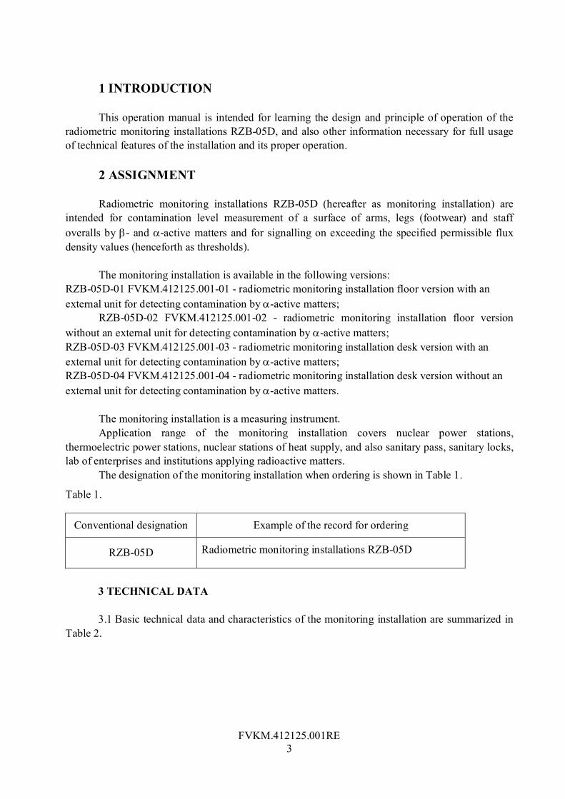
Figure 1 - The radiometric monitoring installations RZB-05D-01. Appearance
Figure 2 - The radiometric monitoring installations RZB-05D-02. Appearance
Unit BDZA-96
Sensor of object presence Unit
“Arms”
Unit “Legs”

FVKM.412125.001RE
7
Figure 3 - The radiometric monitoring installations RZB-05D-03. Appearance
Figure 4 - The radiometric monitoring installations RZB-05D-04. Appearance
4 COMPLETE SET 4.1 The delivery set of the monitoring installation is listed in Table 4.
Table 4.
Component parts Quantity in RZB-05D-ХХ
Designation Name 01 02 03 04
GKPS.400100.000 Unit "Arms" 1 1 1 1
GKPS.400200.000 Unit "Legs" 1 1 - -
GKPS.400400.000 Rack 2 2 2 2
GKPS.400500.000 Basis - - 1 1 ТЕ2.328.001 Detecting block BDZA-96 1 - 1 -
4.2 The STF set of the device may include, on the Customer’s request, the following items:
an additional detecting unit, additional sensors of object presence, etc.

FVKM.412125.001RE
8
5 DESIGN AND PRINCIPLE OF OPERATION 5.1 Design of the monitoring installation 5.1.1 The monitoring installation (figure 5) consists of a device for detecting contamination
of arms by β-active matters with the built-in device of processing and displaying the obtained information (unit "Arms"), device for detecting contamination of legs (footwear) by β-active matters (unit "Legs") and external BDZA-96 unit for detecting contamination by α-active matters.
Figure 5 - General block-diagram of the monitoring installation
5.1.2 The unit "Arms" is the main unit of the monitoring installation and contains: - central processor device (CPD); - four display units (DU); - two detecting units of β-radiation (UD) with photosensors of object presence. The UD of a right arm is structurally executed as a demountable unit and can be used for
detecting contamination of other parts of a body or overalls. The unit "Arms" can be used without the unit "Legs", as an autonomous unit, and has
connectors for connecting to AC mains with supply voltage of 220V and external BDZA-96 unit for detecting contamination by α-active matters.
Left leg Right leg
Left arm Right arm
Alfa-unit Unit "Arms"
~220 V
Unit “Legs”
CPD
DU 2 DU 1
DU 3
DU 4
UD 2 UD 1
UD 3
UD 4
UD 5
UD 6

FVKM.412125.001RE
9
5.1.3 The unit "Legs" contains four UDs with photosensors of object presence and can be used only together with the unit "Arms", which is fastened using two racks.
5.1.4 The CPD, DU and UD are made as separate printed circuit boards, which are connected parallel using 10 wire cable (harness) ensuring a power supply of devices and information transmission according to the requirements of the standard interface bus I2C (Inter-Integrated Circuit Bus).
The CPD executes the functions of a master device, and another units – a function of slave devices, at that, the unique address is assigned to each slave device structurally (in the connector of a wire cable).
All the UDs and DU printed circuit boards are interchangeable, permit rearrangement and replacement of units without additional adjustment and checking.
5.1.5 The operation of the monitoring installation, when detecting β-radiation, is performed as follows:
- the CPD sets all the UDs to performing a pulse counting with checking of excess of a specified threshold of contamination and with the registration of a previously measured background;
- the CPD determines the moment of installation of arms and legs on a measuring site proceeding from the condition of photosensors of object presence, and gives a command to start counting on all the UDs;
- the UD performs contamination measurement of object, placed on it, compares the obtained value with the threshold value and send signal to the CPD about finishing the measurement;
- the CPD, having received a signal about finishing the measurement with the UD, reads out count results, processes them using the calibration data stored in a nonvolatile memory of the UD and outputs a final result to the appropriate DU.
At detecting of α-radiation, the pulses from the external BDZA-96 unit go directly into the CPD, where they are calculated and processed using the calibration data stored in a nonvolatile memory of the CPD. The final result is output to one of the DUs.
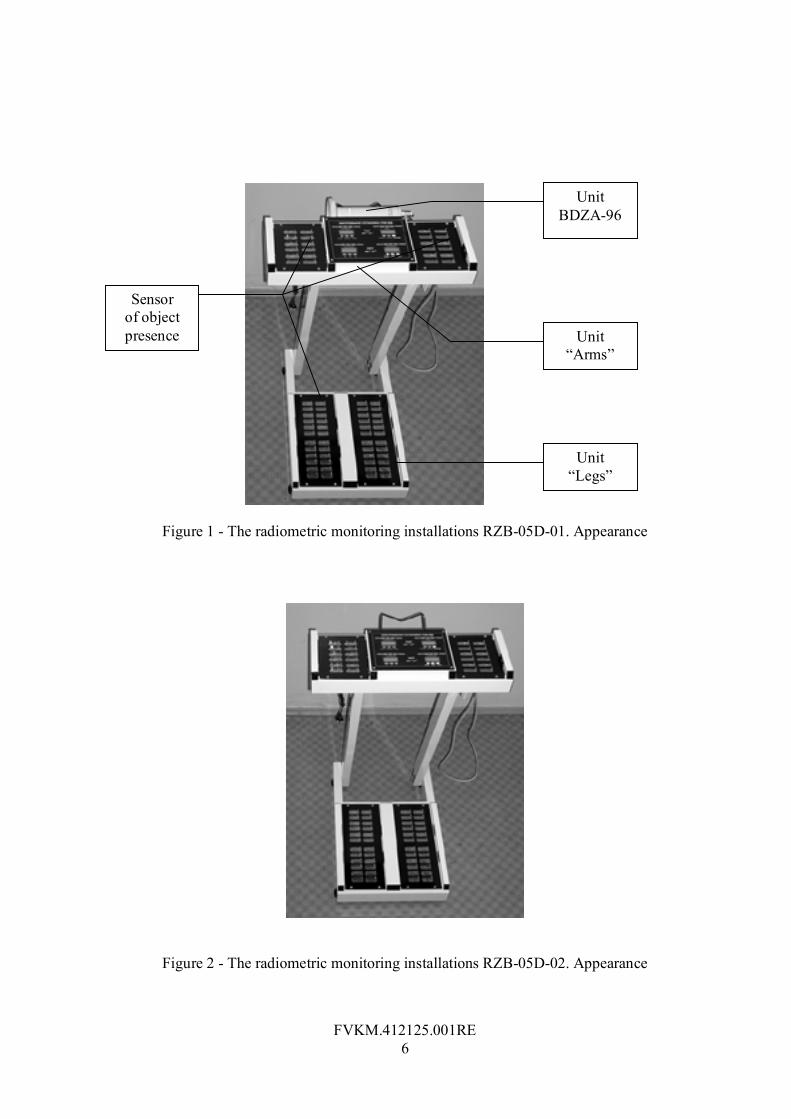
5.1.6 The block-diagram of a central processor device is shown in figure 6 and contains: - stabilized power supply unit (SSU); - single-chip microcontroller (SMC); - power supply supervisor of the microcontroller (SF); - nonvolatile memory (SROM); - pulse shaper (PS) BDZA-96; - audio-signal generator (SG); - connectors for connecting the UD, DU and BDZA-96.
FVKM.412125.001RE
10
Figure 6 - Block-diagram of a central processor device
The SSU generates a stabilized voltage +5V to provide a power supply of the microcontroller, DU and UD, and also a voltage +7V for feeding the external BDZA-96 unit for detecting contamination by α-active matters.
The SMC (microprocessor AT89C52) carried out a program control of all parts of the monitoring installation, data processing and its transfer via the I2C bus.
The SF is intended to control the +5V voltage, feeding the SMC, and to restart the last in case of an inadmissible decrease or momentary cut-out of a line supply voltage. With this, the operation of the monitoring installation is similar to operation after turning on the «Сеть» (“Power”) switch.
The nonvolatile memory (AT24LC02B) with serial data transfer serves for storage of the calibration information for the external BDZA-96unit for detecting contamination by α-active matters, and also other information about functioning of the monitoring installation as a whole.
In connection with the fact that the pulse duration generated by the external BDZA-96 unit is less than the value required for the sure count with the SMC, the FS, expanding a pulse duration approximately for 3 mcs, is used.
The audio-signal generator is used for signalling on measurement termination and in other cases, when it is required to attract attention of the user or attending personnel.
The separate connectors for connecting the group of display units and group of detecting units are installed on the CPD board that allows to simplify operation when adjusting the equipment. The third connector is intended for connection with the external BDZA-96 detecting unit, and also for query of end sensors of remote units’ position and key of the sanction of transition to a setup mode.
to UD
~220 V
SROM
AT89C52 24LC02
Bus I2C
to DU
SSU SG
PS SMC
SF

FVKM.412125.001RE
11
5.1.7 The block-diagram of the UD is shown in figure 7 and contains: - microcontroller (PIC); - nonvolatile memory (SROM); - pulse converter of voltage (PCV); - six gas-discharge G-M counters such as Beta - 2 (BD1 … BD6); - six binary pulse counters (СТ2); - photocurrent amplifier (APC).
Figure 7 - Block-diagram of a beta-detector
The UD is a functionally completed microprocessor device with the I2C interface, which
requires an external power supply with a stabilized voltage of +5V, and permits to make counting and processing of pulses in several modes.
+200 V
-200 V
+5V
PIC
16C62 24LC02
I2C Bus СТ2
SROM
СТ2
СТ2
BD1
BD3
BD2
BD5
BD6
BD4
To photo-sensors
of object
presence
To CPD
PCV APC
СТ2
СТ2
СТ2

FVKM.412125.001RE
12
The UD can operate both autonomously, and under the control of an external controller together with other devices integrated in a common measuring system using the I2C bus.
The operating supply voltage of 400V for the Beta-2 counters is formed by a bridge PCV with an external excitation that operates at fixed frequency generated by the PIC-controller.
The pulses from each gas-discharge counter income at the input of its own binary two-digit counter with reset (СТ2) for preliminary accumulation. The PIC-controller reads out the readings of preliminary counters each millisecond and resets them, storing a total sum during measurement on each of six channels. Thus, the possibility of controlling the functionability of each gas-discharge Beta – 2 counter and signalling of its failure is provided.
The nonvolatile memory (SROM) is intended for storage of the calibration data of the unit for each isotope monitored and other information, the access to which one is performed via the I2C bus.
The measuring system can contain some simultaneously working UDs, which have unique slave-addresses, and SROM in each of them have the same slave-address. Thus, only one SROM chip should actively function on the I2C bus in each instant. It is reached by enabling/disabling a power supply of its SROM by the PIC-controller of the UD through the command via the I2C bus.
Each detecting unit has an input for connecting a photosensor of object presence, designed as a diode optoelectronic coupler with an opened light channel. When performing a query of a such sensor status, the PIC-controller generates a supply pulse of the light-diode radiator and checks a signal level incoming from the photodiode receiver through the APC.
Constructively, the UD is made as a plate with mounted on it gas-discharge counters and printed circuit boards closed by a metallic cover.
For connection with the monitoring installation the UD has 14- wire cable ending in the connector.
When installing into the unit "Arms" or "Legs", the UD is covered by a lavsan film and removable grating, which provide mechanical protection and damp-proofing, and also ease of deactivation.
5.1.8 The detecting BDZA-96 unit is a functionally and constructively completed device which requires an external power supply with a stabilized voltage of +7V and generates positive pulses with duration of 1 … 2 mcs and frequency, proportional to flux density of α-particles.
5.1.9 The DU is a functionally completed microprocessor device with the I2C interface that requires an external power supply with a stabilized voltage of +5В.
The DU allows to display information as a numeric value on 4-digit seven-segment light-emitting-diode indicator and by means of three check light-emitting diodes (green, yellow, red), and also to enter information using three buttons.
The DU is made on a separate printed circuit board with an interface connector and is fastened using four screws from the backside of the display and control panel.
5.1.10 The display and control panel, which appearance is shown in figure 8, contains four interchangeable DUs, and is intended for displaying measurement results, viewing the specified parameters, adjusting and checking the monitoring installation.

FVKM.412125.001RE
13
Figure 8 - Appearance of the display and control panel
The whole panel is divided into four information zones, upper of which concern the results of measurement of the left and right hand, accordingly, and lower zones –of the left and right leg, accordingly.
In each information zone there is a four-digit indicator for displaying a numeric value of measurement result of surface contamination in min–1 сm-2, and three light-emitting diode indicators showing the result of its comparison with maximum permissible levels of contamination by β- or α-active matters (thresholds): "green" – clean, "red" - dirty, "yellow" - measurement process.
The control buttons, marked by a primary color, are accessible in the basic operational mode, and these marked by an additional dark color, are accessible only in setup and calibration modes.
The assignment of buttons is listed in Table 5. Table 5.
Button name Basic mode Setup and calibration modes
CANCELLATION not used Cancellation of value editing in the "Value" zone
SELECTION not used Parameter selection
Zon
e of
the
left
hand
"P
aram
eter
" fie
ld
ENTRY not used Entry of the value entered in the "Value" zone
MODE not used not used
Zon
e of
th
e ri
ght
hand
"U
nit"
fie
ld
SELECTION not used Selection of the detecting unit

FVKM.412125.001RE
14
Button name Basic mode Setup and calibration modes
NUCLIDE Viewing the name of a measured nuclide Selection of a nuclide
not used Moving to the left along the digits when setting the parameter value
not used
Search for numbers within the digit when setting the parameter value
Zon
e of
the
left
leg
"V
alue
" fie
ld
not use
Moving to the right along the digits when setting the parameter value
THRESHOLD Viewing of the specified thresholds not used
BACKGROUND Viewing of background values not used
Zon
e of
the
righ
t leg
"R
esul
ts"
Fiel
d
TEST
1) Starting the measurement irrespective of object presence 2) Starting the measurement at using the remote BDZA-96 detecting unit
Starting the measurement
5.2 Operation principle of the montoring istallation The operation of the monitoring installation is based on calculation of the number of pulses,
xN , generated for time xt in detecting units under effect of ionizing radiations, and further mathematical processing with using models and algorithms to be considered further.
5.2.1 Mathematical model of the beta - detector. A conversion function of one gas-discharge Beta – 2 counter can be presented as follows
x
xx F
FaE
Y1
60100 , (1)
where xY - estimation of beta-parts flux density, min-1 cm2; E - efficiency of a counter, %; a - effective area of a counter, cm2; - dead time of a counter, c;
xxx tNF / - pulse repetition frequency, Hz;
xt - pulse accumulation time, s;
xN –number of pulses registered.
FVKM.412125.001RE
15
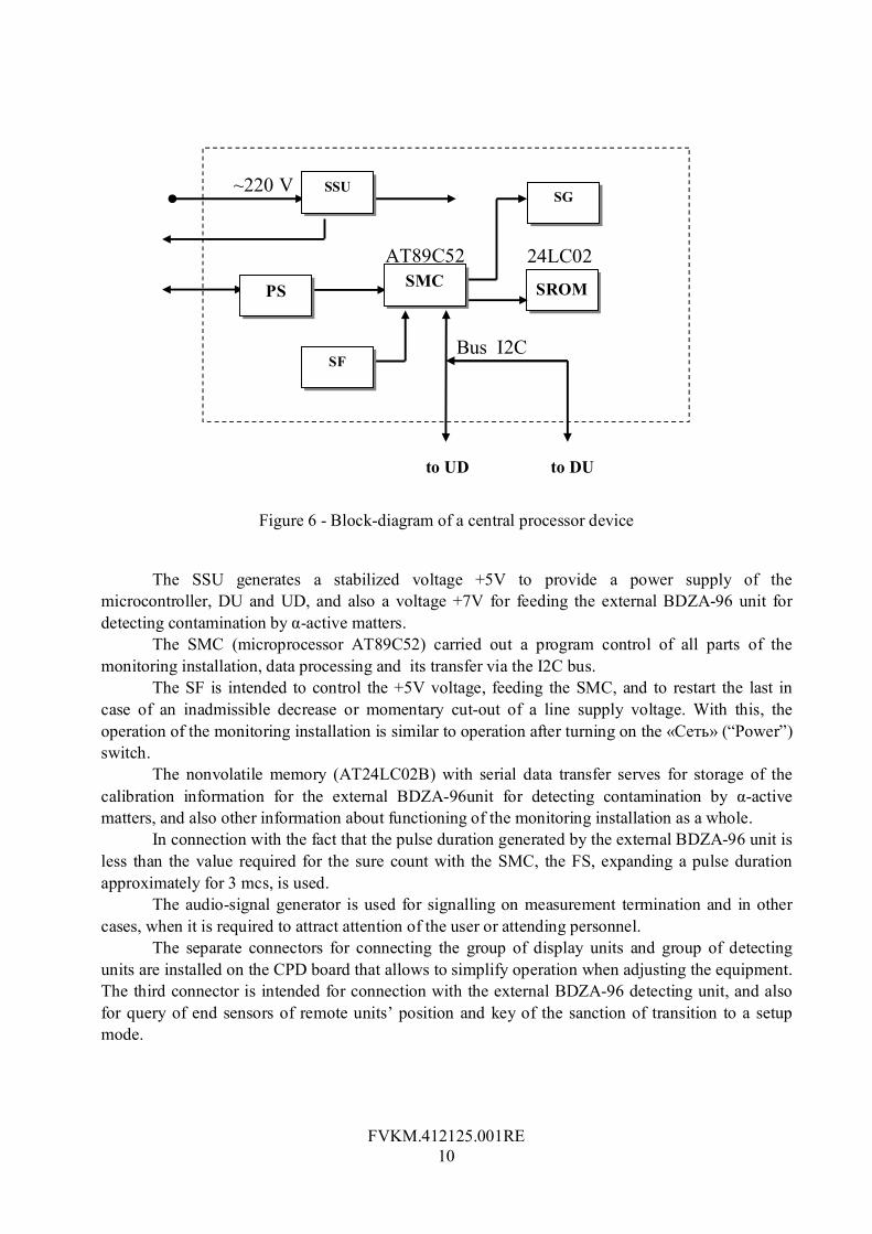
When registrating a total number of pulses generated by the unit from k of Beta - 2 counters, and saving a physical sense of values Е and , the conversion function of the unit looks like
x
xkx Fk
FaE
Y 60100 (2)
or, taking into account 210 cma and 6k
x
xx F
FE
Y6
600 (3)
Even in absence of the object to be measured, the beta-detector generates pulses, which can be caused by an ambient gamma - background, intrinsic background of counters or contamination of a surface of the detector by -active matters.
Taking into account that the background level should not exceed values lying on a linear part of the conversion characteristic of the detector, it can be written as follows
fonfon
fon FE
FE
Y 100
6600 (4)
Having determined the background level before installing the object checked, the contamination level of the last with taking into account (3) and (4) can be presented as follows
fonx
xfonxo F
FF
EYYY
66100 (5)
The measuring error of flux density depends mainly on a random relative error of registration of the number of pulses, the limiting value of which one can be determined as follows
%2001002
xx
xN NN
N
(6)
Therefore, for obtaining a measuring error less than the specified о , %, the number of accumulated pulses should meet condition
2
4104
оxN
(7)
5.2.2 Control of measured object contamination. The control of object contamination is performed by measuring β-radiation flux density, oY ,
coming from the measured object, and its comparison with a maximum permissible level of β-radiation, nY , called a contamination threshold.
Taking into account that the value fonox YYY is measured with a absolute error xY , the conditions, under which one can make unambiguous conclusion about object contamination, are formulated as follows
"Precisely clean" - fonnxx YYYY (8)
"Precisely dirty" - fonnxx YYYY (9)

FVKM.412125.001RE
16
If the conditions (8) and (9) are not satisfied, it is necessary: - either to reduce a measuring error by increasing time of pulse accumulation; - either to take compromise decision by comparison fonnx YYY without regard for a
measurement error. As the measurement result and its error are related to the registered number of pulses, it is
more convenient to pass to conditions on N , that is xx NY , nn NY and fonfon NY . For this purpose, using (3), we shall receive an inverse function of conversion
x
x
xx
EYtNF 600
6 (10)
Having applied (6) and (10), we receive the following conditions instead of (8) and (9)
"Precisely clean" - ox
xx Pt
NN
2 (11)
"Precisely dirty" - ox
xx Pt
NN
2 (12)
where
fonn
o
YYE
P600
6
The time of measurement xt , required for unambiguous conclusion about object’s contamination, depends on a ratio of values xY and fonn YY and can make from units up to tens of
seconds. Thus, after starting the process of pulse accumulation, xN , it is necessary to check up periodically the fulfillment of conditions (11) and (12).
In the monitoring installation such check is performed every 2 seconds within 30 seconds, i.e. itx 2 , where 15...1i is the measurement step number.
With this, conditions (11) and (12) will take the following view:
Precisely dirty" – ioi PPiN2
121 (13)
"Precisely clean" – ioi PPiN2
121 (14)
where iN is a total number of pulses accumulated within i measurement steps. If any of conditions (13), (14) is not satisfied on the 15-th step, the decision is made
proceeding from the following principle
"Dirty" - oPN 3015 (15)
"Clean" - oPN 3015 (16)

FVKM.412125.001RE
17
From the formulas (13) and (14) one can see, that the values of quantities iP and
iP for all steps of the measurement can be calculated beforehand and should be updated only at change of nY or fonY .
5.2.3 Measurement of a background. At turning on the monitoring installation, the background level of each detector is measured
within 25 seconds and stored in its RAM. During the further operation, the CPD controlling a condition of photosensors, determines
the moment, when the objects are absent on all detectors, and starts again a background measurement after delay per 5 seconds. The new value of a background is determined as an arithmetical mean of values obtained as a result of measurement and these stored in the RAM. The table of values
iP and iP is renovated along with updating a background level in the RAM.
At appearance of the object on any of the detectors during the measurement of a background, it is interrupted and a background value is not changed.
5.2.4 Calibration of detectors. From a function (5) one can see, that the values of quantities Е and should be determined
for each detector with a required accuracy before performing measurements. The efficiency of the detector E determines a slope of a linear part of an actual conversion
characteristic at low levels of a measured β-radiation flux density, and the dead time corrects nonlinearity of the characteristic at high levels.
For determination of E and , at least two operating standards of Category 2 of 6СО CP1 (100…1000 min-1сm-2) and CP2 (3000…9000 min-1сm-2) types with a known flux density 1CPY and
2CPY , lying in the center of a linear area and in the top of the full conversion characteristic, accordingly, should be used.
After measuring a background level in absence of calibration plates fonF , a СР1 plate is
installed and 1CPF is measured. The efficiency value of the beta - detector is evaluated by the following expression
fonCPCP
FFY
E 11
100 (17)
Then, a СР2 plate is installed and 2CPF is measured. Dead time is evaluated by the following expression
fonCPCP FYEF
1006006
22 (18)
The obtained values are stored in a nonvolatile memory of each detector and used later by the CPD for representation of measurement results.
The calibration of the BDZA-96 unit is carried out similarly, using the same ratio, and differs only in the fact that the background level is equated to zero, and all calibration factors are stored in a nonvolatile memory of the CPD.

FVKM.412125.001RE
18
6 LABELLING AND SEALING 6.1 On each unit being part of the monitoring installation, the following marking
identifications are made: - trade mark of the enterprise - manufacturer; - conventional designation; - factory serial number; - year of manufacturing. 6.2 Sealing of the UD is made by mastic, which fills a recess for the head of one of screws,
fastening a cover to the unit. 7 TARE AND PACKAGING 7.1 Before packaging it is necessary to prepare the monitoring installation, kit of spares and
operating documentation as follows: а) subject the monitoring installation to conservation in accordance with the technique
described in item 18.3 of this manual; б) put the kit of spares, connecting cables and operating documentation into polyethylene
bags. 7.2 At packaging it is necessary to fill in all free places by a corrugated cardboard for
preventing movement inside tare. 8 SAFETY MEASURES 8.1 Before operating the monitoring installation it is necessary to acquaint with this
operation manual. 8.2 When operating the monitoring installation, the following safety measures should be
followed: а) the monitoring installation should be safely grounded using an electrical connection of the
terminal «», arranged on a back panel of the unit "Arms", to the grounding mat. The cross-section of a grounding conductor should be no less than 1,5 mm2.
b) the attending personnel should be familiar with and observe operating instructions of electric installations and safety precaution regulations when operating the installations.
8.3 When performing routine maintenance and repair, it is not allowed to leave the monitoring installation alive with a removed cover without supervision.
8.4 When operating the monitoring installation, it is necessary to observe sanitary regulations and norms of radiation safety.
9 SEQUENCE OF MOUNTING 9.1 The monitoring installation can be installed both on a horizontal floor surface (RZB-
05D-01 and RZB-05D-02 models), and on horizontal desk surface (RZB-05D-03 and RZB-05D-04 models).

FVKM.412125.001RE
19
9.2 The monitoring installation is intended for operation in rooms free of vapors of acids, alkalis and aggressive gases. The ambient temperature should be in the range of from minus 10° to +50°С, relative humidity - no more than 95 % at temperature +35°С, atmospheric pressure in the range of 86 to 106 kPa (650…800 mm.Hg).
9.3 If the monitoring installation was under conditions with temperature below from minus 10°С, then it should be maintained under operating conditions within 24 hours before turning it on
10 PREPARATION OF THE MONITORING INSTALLATION FOR OPERATION 10.1 The monitoring installation is maintained by a person, having a special training and
familiar with this technical description. 10.2 Mount the monitoring installation on a workstation. 10.3 Ground safely the monitoring installation according to the requirement of item 8.2 of
this technical description. 10.4 Connect the AC cable and remote detecting BDZA-96 (RZB-05D-01 and RZB-05D-03
models) unit. Insert a cable plug into a socket with AC voltage of 220V. 10.5 Put the “Power” switch to ON position. Let the monitoring installation to warm up
within 5 minutes. 10.6 After powering on, the installation passes in a mode of testing. First, all light-emitting
diodes and segments of indicators on the display and control panel are on, then the installation passes in a mode of automatic measurement of an intrinsic background of all the UDs. With this, on all indicators the message "____" appears. The measurement duration is about 100 seconds. After performing the measurement, the result as "FXXX" is displayed. Further measurement of an intrinsic background is made permanently before appearing the measurement object.
In the case of failure of one of the UDs or excess of a self-contamination threshold, the error code "ErXY" for the appropriate UD is displayed, and the red light-emitting diode is on. The list of faults is given in Table 8 (item 16.2).
10.7 The factors (See Appendix А TD) and threshold values of the alarm signalling for various nuclides have been stored by the enterprise - manufacturer in a nonvolatile memory of the UD. The sequence of nuclides and their designation are included into the logbook of the device
The threshold values of the alarm signalling for various nuclides are summarized in the following Table:
Nuclide Nuclide designation * Threshold value, min-1cm-2
Sr-90Y-90 n0 20 Tl-204, F-18 n1 100 Cs-137 n2 100 Co-60, Tc-99 n3 100 O-15 n4 100 N-13, Sr-89 n5 100 C-11 n6 100 I-131, Na-22 n7 100 Ru-106Rh-106 n8 100 Tc-99m и I-123 n9 9000
* - The sequence of nuclides and their designation are included into the logbook of the device

FVKM.412125.001RE
20
If required, set another threshold value of the alarm signalling (see item.11 of this TD). It is necessary to avoid setting too low values (close to the background value of the UD),
since it will cause increasing the measurement time of the object. 11 OPERATION PROCEDURE 11.1 Determination of contamination of arms and legs (footwear) by β-active matters should
be performed in the following sequence. Get up on the basis of the device (unit "Legs") so that feet of legs have appeared on the
middle of grounds (RZB-05D-01 and RZB-05D-02 models). Apply the palms of arms to detecting units of the upper unit (unit "Arms") so that to overlap an optical axis of sensors of object presence. If all optical axises of sensors are overlapped, the monitoring installation will pass in a mode of measurement. With this, all yellow light-emitting diodes on the control and indication panel will light on and on all indicators "----" will appear.
Do not change arrangement of legs and arms until a short audio signal (all "Clean") or series of short audio pulses (even one unit has fixed "Dirty") sounds and red ("Dirty") or green ("Clean ") light-emitting diodes on the panel is on. The measurement time makes from 2 to 30 seconds and depends on a set threshold value and degree of object contamination. Remove arms from sensors of the upper unit and leave the basis of the installation.
The indicator readings will correspond to measured flux densities for arms and legs. For nuclides n0 – n8 -in an integer-valued format «ХХХХ», for a nuclide n9 (-radiation) - in a decimal format Х.ХЕХ (for example, 4.1Е2 will correspond to 4100 min-1cm-2).
11.2 Determination of contamination of a body (clothes) by β-active matters using a remote detecting unit should be carried out in the following sequence.
Standing on a basis of the installation or near it, touch the lever of the detecting unit of a right hand and remove it. On the indicator in the "Unit" field an inscription "bEtA" will appear, which means, that the measurements will be made with a remote detecting unit of β-radiation. On the indicator, in the "Parameter" field an inscription "Р" ("Threshold") will appear, and on the indicator, in the "Value" field the set threshold value will be displayed. Apply the remote unit to the examined part of a body (clothes).
To start the measurement, overlap by an arm, and then make free the sensor of object presence of a right hand, or press the "Test" button. On the indicator in the "Result" field an inscription "----" will appear, and the yellow light-emitting diode will turn on.
Do not change arrangement of the sensor until the short audio signal ("Clean") or a series of short audio pulses ("Dirty") sounds, and red ("Dirty") or green ("Clean") light-emitting diodes on the panel are on. The measurement time of the object makes from 2 to 30 seconds and depends on the set threshold value and contamination degree of object.
Repeat measurements on the other parts of a body (clothes). After finishing measurements place carefully the unit on its nominal place, pushing it into up to typical "click" of the latch.
11.3 Determination of contamination of a body (clothes) by α-active matters with the remote BDZA-96 detecting unit (RZB-05D-01 and RZB-05D-03 models)should be carried out in the following sequence.
Standing on a basis of the installation or near it, touch a mean part of the detecting BDZA-96 unit located on a back panel of unit "Arms" and remove it from brackets. On the indicator in the "Unit" field an inscription "ALFA" will appear, which means, that the measurements will be made

FVKM.412125.001RE
21
by the remote detecting unit of α-radiation. On the indicator, in the "Parameter" field an inscription "Р" ("Threshold") will appear, and on the indicator, in the "Value" field the set threshold value will be displayed. Remove a protective cover from the remote unit and apply the unit by a broad part to the examined part of a body (clothes).
To start the measurement, overlap by an arm, and then make free the sensor of object presence of a right hand, or press the "Test" button. On the indicator, in the “Result” field an inscription "----" will appear, and the yellow light-emitting diode will turn on.
Do not change arrangement of the sensor until the short audio signal ("Clean") or a series of short audio pulses ("Dirty") sounds, and red ("Dirty") or green ("Clean") light-emitting diodes on the panel are on. The measurement time of object makes from 2 to 30 seconds and depends on the set threshold value and contamination degree of object.
Repeat measurements on other parts of a body (clothes). After finishing the measurement place carefully the unit on its place. 11.4 To view the set threshold values, press the "Threshold" button in a right lower corner of
the display and control panel. The values of response levels of the alarm signalling (min-1сm-2) for detecting units of arms and legs will appear on indicators. The threshold values are displayed until pressing other buttons or beginning the measurement process.
11.5 To view a background value of detecting units, press the "Background" button in a right lower corner of the display and control panel. The indicator readings will correspond to the background values for detecting units. For nuclides n0 – n8 - in an integer-valued format «ХХХХ», for a nuclide n9 (-radiation) – in a decimal format Х.ХЕХ (for example, 0.4Е4 will correspond to 4000 min-1cm-2).
The background values are displayed until pressing other buttons or beginning the measurement process.
11.6 To view the set type of a nuclide measured, press the "Nuclide" button in a right upper corner of the display and control panel. On indicators, names of nuclides measured of detecting units of arms and legs as «n0» at contamination measurement on Strontium 90 - Yttrium 90, and «n<nuclide number >» at contamination measurement on nuclides 1-9. The nuclide number is displayed until pressing other buttons or beginning the measurement process.
11.7 To start the measurements irrespective of presence of object, press the"Test" button in a right lower corner of the display and control panel. On indicators, the "----" inscription will appear, all yellow light-emitting diodes will turn on and the short audio signal will sound when the measurement stops. The measured values will appear on indicators.
12 CALIBRATION TECHNIQUES 12.1 Devices and equipment The devices and equipment required for calibration are listed in Table 6.
Table 6
Name Type Quantity
Operating standard Sr-90Y-90 of Category2 6СО 3
Operating standard Pu-239 of Category 2 5П9 3

FVKM.412125.001RE
22
12.2 Calibration conditions 12.2.1 Calibration should be performed in accordance with the State Standard (GOST)8.070-
95 at a natural radiation background under normal climatic conditions: - ambient temperature (20 ±5) °С; - relative humidity of air from 30 to 80 %; - atmospheric pressure from 84 up to 106 kPa. 12.2.2 The primary calibration should be performed for the monitoring installation delivered
from the manufacture and after repair which caused graduation of the installation. The periodical calibration should be performed for the monitoring installation being in
operation and storage. 12.2.3 Calibration of the monitoring installation is performed by territorial bodies of the
State Committee on Standards once per year for the monitoring installation being in operation, and once per three years for the monitoring installation being in storage.
12.3 Calibration procedure Conduct a visual inspection of the installation, paying attention to the following: - complete set of the installation; - availability of a calibration certificate (at re-calibration); - presence and safety of marking; - absence of corrosion, impurities, damages. 12.3.2 Check a general functionability of the installation, performing operations according to
items 10, 11. 12.3.3 Determine values of basic errors of flux density measurements of α-, β-radiation
according to the technique described in items 13, 14. 12.3.4 At a negative result of calibration in case if the measuring error does not fall outside
the limits of 0.5-1.5 from a rated value, perform setup of the device according to item 15 (Setup) and repeat calibration according to 12.3.3.
12.3.5 In case if the measuring error is outside the stated limits, the device is subjected to repair at the enterprise - manufacturer.
12.4 Executing of calibration results The calibration results are executed by the calibration certificate. 13 DETERMINATION OF BASIC MEASUREMENT ERROR VALUE OF Β-RADIATION FLUX DENSITY Prepare for operation and switch on the monitoring installation according to item 10. After performing an automatic self-test and measurement of a background make sure that a
nuclide 0 (Sr90-Y-90, item11.6) is selected. In the case if the another nuclide is chosen, pass in a setup mode (15.1), select a mode of
setting an alarm response threshold (15.4) and chose a nuclide 0 by pressing the “Nuclide” button. Exit from the setup mode (15.12).

FVKM.412125.001RE
23
After performing an automatic measurement of a background, overlap an optical axis of the sensor of object presence of the selected UD, arrange on it a flat source of a 6СО type (no below than Category 2) and perform no less than 5 measurements using the "Test" button (11.7).
Determine a basic error of measurements in percentage by a formula
1000
0
P
PPm , (19)
where P - is a mean arithmetic reading of the monitoring installation at each value of β-radiation flux density mentioned below;
0P - is a true value of β-radiation flux density. The value of basic error for all values should not fall outside the limits, indicated in Table 2. Carry out the measurements on plates with a rated value of β-radiation flux density of 100,0 -
300; 3000 - 5000; 7000 - 9000 min-1сm-2. Setup. If the setup is required (value of basic error falls outside the limits indicated in Table 3),
carry out operations of item 15 (Setup). 14 DETERMINATION OF BASIC ERROR VALUE AND MEASUREMENT RANGE OF Α-RADIATION FLUX DENSITY Prepare for operation and switch on the monitoring installation according to item 10. After performing an automatic self-test and measurement of a background, remove the
remote BDZA-96 unit from brackets, remove a protective cover and place it on a flat source of 5П9 type (no below than Category 2) and perform no less than 5 measurements according to item 11.3.
Determine a basic error of measurements in percentage by a formula
1000
0
P
PPm , (20)
where P - is a mean arithmetic reading of the monitoring installation at each value of α-radiation flux density mentioned below;
0P - is a true value of α-radiation flux density. The value of basic error for the entire measurement range should not fall outside the limits,
indicated in Table 2. Carry out the measurements on plates with a rated value of α-radiation flux density of 50 –
300; 3000 - 5000; 7000 - 9000 min-1сm-2. Setup. If the value of a basic error falls outside the limits, indicated in Table 3, perform operations
of item 15 (Setup). 15 SETUP OF THE MONITORING INSTALLATION 15.1 Transition to setup mode of the monitoring installation Prepare for operation and switch on the monitoring installation according to item 10. To pass in a setup mode of the monitoring installation, turn the key of access located on a
back panel of the unit "Arms", and press the "Mode" button located in the "Unit" field of the display and control panel. The installation will pass in a setup mode.
If the key of access is on the horizontal position, then at powering on the monitoring installation pass directly in a setup mode.

FVKM.412125.001RE
24
With this, a number of the detecting unit adjusted, as "d1" will appear in the "Unit" field. In the "Parameter" field the parameter name as "StAt" will appear. In the “Value” field the value of a selected parameter will appear.
15.2 Checking operation of the sensor of object presence Pass in a setup mode of the monitoring installation, according to item 15.1. Select the unit by clicking the "Selection" button in the "Unit" field (d1-d2-d3-d4-d5-d6-
ALFA-d1 etc.). Select the parameter "StAt" («for n0»: StAt-Fon-P-EFF-tAU-CP1-CP2-StAt, etc; for «n1-n9»: StAt-Fon-P-EFFn-StAt) in the "Parameter" field by clicking the button "Selection" of this field.
In the "Result" field the parameter value as "00" or “01”will appear. To check the operation of sensor of object presence of this unit, overlap the appropriate light-emitting diode pair. If the sensor is good, a parameter value should to change for " 80" or “81”.
15.3 Measurement of a background of detecting unit in a setup mode The background of the UD is automatically measured and stored after turning on the
monitoring installation in the main mode. If the measurement of a background was not finished, it can be repeated in a setup mode. For this purpose perform the following operations.
Pass in setup mode of the monitoring installation, according to item 15.1. Select the unit by clicking the"Selection" button of the "Unit" field (d1-d2-d3-d4-d5-d6-
ALFA- CPU-CHEC -d1 etc.). Select the "Fon" (for «n0»: StAt-Fon-P-EFF-tAU-CP1-CP2-StAt, etc.; for «n1-n9»: StAt-Fon-P-EFFn-StAt) parameter in the "Parameter" field by clicking the "Selection" button of this field.
The current value of a background as "ХХХХ" will appear in the "Value" field. If a background has not been measured yet, the value can be whatever. To perform the measurement of a background, press the "Test" button in the "Result" field. On the right lower indicator (in the "Result" field) the message "____" will be displayed for 30 seconds, and then a new measured background value of the UD as "ХХХХ" will appear. To store a new value of a background, press the "Enter" button in the "Parameter" field. Then the old value of a background in the "Value" field will be replaced by the new one.
15.4 Setting a response threshold of the alarm signalling system Pass in setup mode of the monitoring installation, according to item 15.1. Select the detecting unit by clicking the "Selection" button of the "Unit" field (d1-d2-d3-d4-
d5-d6-ALFA-CPU-CHEC -d1 etc.) and an isotope type (for d1 … d6) by pressing the "Nuclide" button. With this, in two last digits of the indicator the «n0» (for Sr90-Y90) or «n1-n9» (for other nuclides) message will be displayed.
Select the parameter "Р" (for «n0»: StAt-Fon-P-EFF-tAU-CP1-CP2-StAt, etc.; for «n1-n9»: StAt-Fon-P-EFFn-StAt) in the "Parameter" field by clicking the "Selection" button. The threshold value as "ХХХХ" will appear in the "Value" field.
To change a parameter value, press any of the "←", "↑", "→" buttons. With this one of digits in the "Value" field will begin to flash. Select the position using the "←", "→" buttons, and set a value of a flashing digit using the "↑" button.
After editing a parameter value, it can be stored by clicking the "Enter" button in the "Parameter" field, and it is possible to refuse change by clicking the "Refusal" button in the "Parameter" field. Then in the "Value" field a new or old parameter value, accordingly, will appear, and the digits will stop to flash.
FVKM.412125.001RE
25
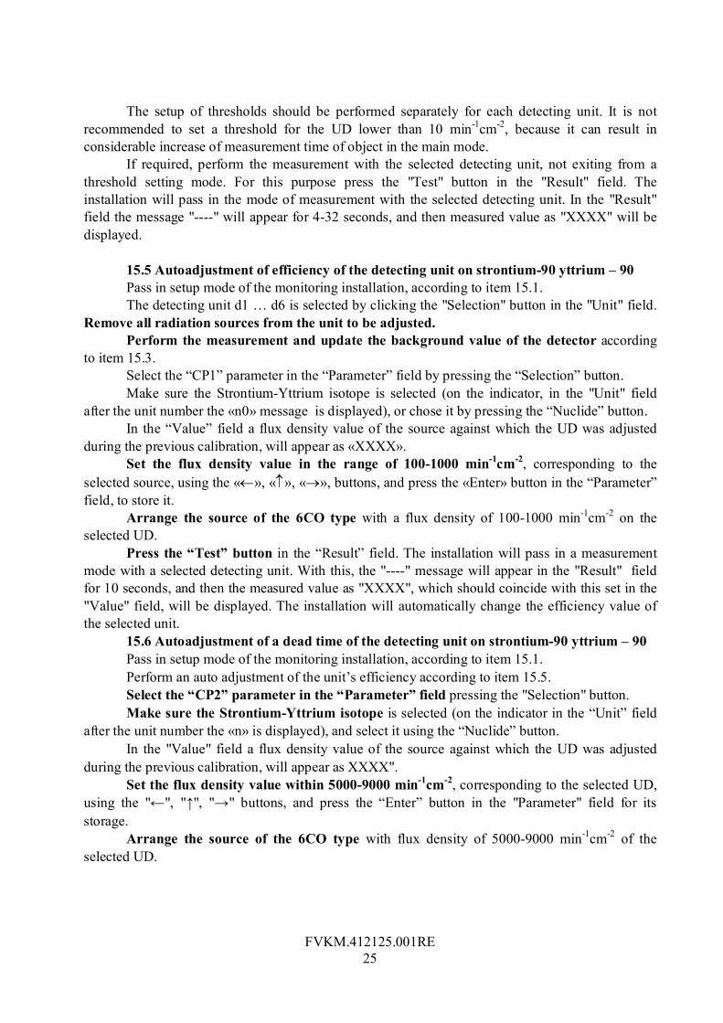
The setup of thresholds should be performed separately for each detecting unit. It is not recommended to set a threshold for the UD lower than 10 min-1сm-2, because it can result in considerable increase of measurement time of object in the main mode.
If required, perform the measurement with the selected detecting unit, not exiting from a threshold setting mode. For this purpose press the "Test" button in the "Result" field. The installation will pass in the mode of measurement with the selected detecting unit. In the "Result" field the message "----" will appear for 4-32 seconds, and then measured value as "ХХХХ" will be displayed.
15.5 Autoadjustment of efficiency of the detecting unit on strontium-90 yttrium – 90 Pass in setup mode of the monitoring installation, according to item 15.1. The detecting unit d1 … d6 is selected by clicking the "Selection" button in the "Unit" field.
Remove all radiation sources from the unit to be adjusted. Perform the measurement and update the background value of the detector according
to item 15.3. Select the “CP1” parameter in the “Parameter” field by pressing the “Selection” button. Make sure the Strontium-Yttrium isotope is selected (on the indicator, in the "Unit" field
after the unit number the «n0» message is displayed), or chose it by pressing the “Nuclide” button. In the “Value” field a flux density value of the source against which the UD was adjusted
during the previous calibration, will appear as «ХХХХ». Set the flux density value in the range of 100-1000 min-1cm-2, corresponding to the
selected source, using the «», «», «», buttons, and press the «Enter» button in the “Parameter” field, to store it.
Arrange the source of the 6СО type with a flux density of 100-1000 min-1сm-2 on the selected UD.
Press the “Test” button in the “Result” field. The installation will pass in a measurement mode with a selected detecting unit. With this, the "----" message will appear in the "Result" field for 10 seconds, and then the measured value as "ХХХХ", which should coincide with this set in the "Value" field, will be displayed. The installation will automatically change the efficiency value of the selected unit.
15.6 Autoadjustment of a dead time of the detecting unit on strontium-90 yttrium – 90 Pass in setup mode of the monitoring installation, according to item 15.1. Perform an auto adjustment of the unit’s efficiency according to item 15.5. Select the “CP2” parameter in the “Parameter” field pressing the "Selection" button. Make sure the Strontium-Yttrium isotope is selected (on the indicator in the “Unit” field
after the unit number the «n» is displayed), and select it using the “Nuclide” button. In the "Value" field a flux density value of the source against which the UD was adjusted
during the previous calibration, will appear as ХХХХ". Set the flux density value within 5000-9000 min-1сm-2, corresponding to the selected UD,
using the "←", "↑", "→" buttons, and press the “Enter” button in the "Parameter" field for its storage.
Arrange the source of the 6CO type with flux density of 5000-9000 min-1сm-2 of the selected UD.

FVKM.412125.001RE
26
Press the “Test” button in the “Result” field. The installation will pass in the measurement mode with the selected detecting unit. With this, the "----" message will appear in the “Result” field for 20 seconds, and then the measured value as "ХХХХ", which should coincide with this set in the "Value" field, will be displayed. The installation will automatically change the dead time value of the selected unit, but the efficiency value will not change.
15.7 Autoadjustment of efficiency of the remote bdza-96 detecting unit Pass in a setup mode of the monitoring installation, according to item 15.1. The detecting unit "ALFA" is selected by clicking the "Selection" button in the “Unit” field. Select the “CP1” parameter by clicking the "Selection" button in the "Parameter" field. In the
"Value" field a flux density value of the source against which the UD was adjusted during the previous calibration will appear as "ХХХХ".
Set a flux density value within 100-1000 min-1сm-2, corresponding to the selected UD, using the "←", "↑", "→" buttons, and press the “Enter” button in the "Parameter" field for its storage.
Arrange the unit on a source of the 5П9 type with a flux density value of 100-1000 min-1сm-2. Press the “Test” button in the “Result” field. The installation will pass in the measurement
mode with the selected detecting unit. With this, the "----" message will appear in the “Result” field for 10 seconds, and then the measured value as "ХХХХ", which should coincide with this set in the "Value" field, will be displayed. The installation will automatically change the efficiency value of the selected unit.
15.8 Autoadjustment of a dead time of the remote bdza-96 detecting unit Pass in a setup mode of the monitoring installation, according to item 15.1. The detecting unit "ALFA" is selected by clicking the "Selection" button in the "Unit" field. Select the “CP2” parameter by clicking the "Selection" button in the "Parameter" field. In the
"Value" field a flux density value of the source against which the UD was adjusted during the previous calibration will appear as "ХХХХ".
Set a flux density value within 5000-9000 min-1сm-2, corresponding to the selected UD, using the "←", "↑", "→" buttons, and press the “Enter” button in the "Parameter" field for its storage.
Arrange the unit on a source of the 5П9 type with a flux density of 5000 - 9000 min 1 сm-2. Press the “Test” button in the “Result” field. The installation will pass in the measurement
mode with the selected detecting unit. With this, the "----" message will appear in the “Result” field for 20 seconds, and then the measured value as "ХХХХ", which should coincide with this set in the "Value" field, will be displayed. The installation will automatically change the dead time value of the selected unit, but the efficiency value will not change.
15.9 Manual correction of efficiency and dead time of detecting units The manual correction of efficiency and dead time of detecting units is available only for the
remote BDZA-96 unit and detecting units of the installation in the mode of measurement of Sr90-Y-90 («n0»).
Manual correction of parameters can be made at absence of calibration plates of the required ratings for performing an auto adjustment of efficiency and dead time of detecting units, and also if required to introduce corrections into their values to compensate the effect of design additions, etc.
FVKM.412125.001RE
27
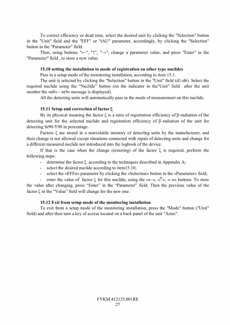
To correct efficiency or dead time, select the desired unit by clicking the "Selection" button in the "Unit" field and the "EFF" or "tAU" parameter, accordingly, by clicking the "Selection" button in the "Parameter" field.
Then, using buttons "←", "↑", "→", change a parameter value, and press "Enter" in the "Parameter" field , to store a new value.
15.10 setting the installation to mode of registration on other type nuclides Pass in a setup mode of the monitoring installation, according to item 15.1. The unit is selected by clicking the "Selection" button in the "Unit" field (d1-d6). Select the
required nuclide using the “Nuclide” button (on the indicator in the"Unit" field after the unit number the «n0» - «n9» message is displayed).
All the detecting units will automatically pass in the mode of measurement on this nuclide. 15.11 Setup and correction of factor By its physical meaning the factor is a ratio of registration efficiency of -radiation of the
detecting unit for the selected nuclide and registration efficiency of -radiation of the unit for detecting Sr90-Y90 in percentage.
Factors are stored in a nonvolatile memory of detecting units by the manufacturer, and their change is not allowed except situations connected with repair of detecting units and change for a different measured nuclide not introduced into the logbook of the device.
If that is the case when the change (restoring) of the factor is required, perform the following steps:
- determine the factor according to the techniques described in Appendix А; - select the desired nuclide according to item15.10; - select the «EFFn» parameter by clicking the «Selection» button in the «Parameter» field; - enter the value of factor for this nuclide, using the «», «», «» buttons. To store
the value after changing, press “Enter” in the “Parameter” field. Then the previous value of the factor in the “Value” field will change for the new one.
15.12 Exit from setup mode of the monitoring installation To exit from a setup mode of the monitoring installation, press the "Mode" button ("Unit"
field) and after then turn a key of access located on a back panel of the unit "Arms".

FVKM.412125.001RE
28
16 POSSIBLE FAULTS AND WAYS OF THEIR REMOVAL 16.1 A list of possible faults and the ways of their removal is given in Table 7.
Table 7
Name of fault Possible reason Ways of removal Note 1. The light emitting diodes of indicator panel are dim when turning the device on
There is no power supply
Check a fuse and a proper connection to AC mains
2. When turning the device on, the «ErXY» message is displayed
Fault in one of the units of the monitoring installation
See instruction on adjustment
X- the unit number Y- error code See Table 8 for details
3. Strong difference of measurement results from rating values of the test plate
Miscalibration of units
Repeat calibration of the detector
4. When removing the remote units, there is no transition to the «ALFA» or «bEtA» mode
The end sensor of the appropriate unit is defective
Check mobility of a tail of the end sensor
5. The measurement process does not start when all six photosensors are locked
One of photosensors is defective
Check the operation of photosensors in a setup mode (see 15.2)
16.2 The list of faults of the monitoring installation units displayed as "ErXY", is given in Table 8. Table 8
Value X Value Y Fault 1 … 7 0 UD № X is absent 1 … 7 1 In UD № X the Beta – 2 counter №1 is faulty 1 … 7 2 In UD № X the Beta-2 counter №2 is faulty 1 … 7 3 In UD № X the Beta-2 counter №3 is faulty 1 … 7 4 In UD № X the Beta-2 counter №4 is faulty 1 … 7 5 In UD № X the Beta-2 counter №5 is faulty 1 … 7 6 In UD № X the Beta-2 counter №6 is faulty 1 … 7 7 In UD № X the high-voltage source is faulty 1 … 7 8 Contamination or excessive background of the UD №X 1 … 7 9 Photosensor of the UD № X is faulty
8 0…9 CPD or DU is faulty 9 0 BDZA-96 is faulty

FVKM.412125.001RE
29
17 MAINTENANCE 17.1 Maintenance is carried out with the purpose of ensuring the proper and continuous
operation of the monitoring installation. The following main kinds and terms of preventive operations are recommended:
- Visual inspection 1 time per month; - External cleaning 1 time per month; - Check of main parameters 1 time per year. 17.2 When performing maintenance, the safety measures stated in section 8 of this Technical
Description should be observed. 17.3 When performing a visual inspection, the conformity of the installation to the
requirements for a complete set and marking is checked. At visual inspection of an external condition it is necessary to check fixation of units,
accuracy of fixation of remote units, reliability of connecting AC cable and leads of the BDZA-96 unit, condition of varnish and galvanic coatings.
17.4 External cleaning is carried out, to avoid contamination of the installation. The dust outside is withdrawn using a soft cloth or brush.
17.5 Check of main parameters is carried out according to the technique described in sections 13 and 14 of this Technical Description.
18 STORAGE RULES 18.1 The monitoring installation should be stored under conditions eliminating a capability
of mechanical damages, in ventilated dry and clean rooms. 18.2 The transport packaging of the installation provides full safety within 6 months under
conditions indicated in item 18.1 of this Technical Description. 18.3 The installation coming to storehouse of a customer and intended for a long-term
storage of more than 6 months, should be subjected to conservation. 18.4 The conservation of the installation should be made by putting it in a film cover with
silica gel. 19 TRANSPORTATION 19.1 The transportation of the monitoring installations can is made by any kind of a transport
at any distances in packaging of enterprise-manufacturer at observing the following rules: - railway coaches, containers, the bodies of automobiles, used for transportation of the
installations, should not have tracks of transportation of cement, coal, chemicals etc.; - the boxes with the installations should be covered by a canvas at transportation by an
opened motor transport; - the boxes with the installations should be located in a heated pressurized section at
transportation by air transport; - the boxes with the installations should be located in hold at transportation by water
transport.
FVKM.412125.001RE
30
19.2 Arrangement and fastening of boxes should provide a steady position throughout the entire journey, absence of displacement and shocks each other.
19.3 At loading and unloading of the installations it is necessary to observe requirements of inscriptions indicated on tare .

FVKM.412125.001RE
31
APPENDIX А
DETEREMINATION TECHNIQUE OF FACTOR ξ FOR THE DETECTING UNIT
А.1 The monitoring installation is prepared for operation and switched on according to the item 10.
Overlap an optical axis of the sensor of object presence of the selected UD. Arrange a source 1СО with a flux density of 6000-12000 min-1сm-2 in middle of one of 12
windows of a protective grating of the selected detecting unit. Make three measurements according to item 11.7. The obtained results should be recorded. Repeat this procedure for all the other windows of a protective grating of the selected UD. Calculate average of the measured value on 36 measurements ( 1Х ). А.2 Arrange a source 1TL with a flux density of 6000-12000 min-1сm-2 in middle of one of
12 windows of a protective grating of the selected detecting unit. Similarly make the measurements. Calculate average of the measured value on 36 measurements ( 2Х ).
Determine a factor ξ by the formula
11
22
//РХРХ
(А.1)
where 1Х - is average of the measured value on 36 measurements for a source 1СО;
2Х - is average of the measured value on 36 measurements for a source 1TL;
1Р - is a passport value of a flux density for a source 1СО (min-1сm-2);
2Р - is a passport value of a flux density for a source 1TL (min-1сm-2). А.3 Determination of for other nuclides is the same.

FVKM.412125.001RE
32
APPENDIX В
TYPICAL DEPENDANCE OF SENITIVITY OF THE MONITORING INSTALLATION ON MAXIMUM ENERGY OF -RADIATION SPECTRUM
Relative sensitivity R(Emax)/R(2.28MeV)
0
0,2
0,4
0,6
0,8
1
1,2
0,16 0,3
0,5
0,7
0,9
1,1
1,3
1,5
1,7
1,9
2,1
2,3
2,5
2,7
2,9
3,1
3,3
3,5
M aximum energy of beta-spectrum, M eV

FVKM.412125.001RE
33
APPENDIX С
ASSEMBLY UNSTRUCTIONS С.1 Put the cable from the “Legs” unit through the hole in the rack.
С.2 Fasten the rack on the “Legs” unit and pass the cable inside the rack.

FVKM.412125.001RE
34
С.3 Fasten the connector at the top of the rack.
С.4 Arrange the “Arms” unit on the rack.

FVKM.412125.001RE
35
С.5 Fasten the “Arms” unit to the rack using four screws.


![[TDS]Bahamut - Episodio 05D](https://img.dokumen.tips/doc/110x75/55cf8f24550346703b99548b/tdsbahamut-episodio-05d.jpg)