Embed Size (px)
Citation preview

Radiation Protection Program Alignment Guidelines and Good Practices
1 | P a g e
Laser alignment is a challenge and it is also the most likely time for a laser-induced injury or accident to occur! In the research setting, over 60% of all laser accidents occur during the alignment process, therefore alignment procedures are very important and should be strictly adhered to.
Laser beam alignment requires work with an open beam and involves directing the beam toward a series of reflective or partially reflective surfaces, such as mirrors or lenses, so that the beam follows some predetermined path. With respect to the laser, alignments may be internal or external.
Internal alignments are those occurring within the laser cavity or head and often place the worker at increased risk of electrical accidents as well as beam exposure. The need for internal alignments arises most often because of problems associated with beam mode or power. Internal alignments are not part of this guide.
External alignments are those that occur from the laser’s end window to some terminal target (beam stop). In between these two locations may be a number of optical components (optics) arrayed in configurations that may be simple (few optics) or quite complex (many optics, multiple tables, extends outside primary area/room, etc.). The need for external alignments occurs because of requirements for an initial setup, reconfiguration of the optical setup, or replacement of components in the open beam path.
The following suggested alignment practices are a compilation of generally work practices that help to reduce the potential for exposure to laser radiation. These practices are most generally applicable to external alignments on the optical table. Getting ready
• It is best to perform alignments with another trained person. Consider having at least one other person present to help with the alignment (colleague or “buddy”).
• Review all procedures before attempting the alignment. • Plan ahead. All equipment and materials needed are present prior to beginning the
alignment. • Personal protective equipment (PPE): alignment eyewear, operational power eyewear,
faces shields for scattered UV, skin protection as necessary is available. • The Principal Investigator (PI) or Supervisor has authorized the persons conducting the
alignment. • Limit access to the room or area to authorized personnel and supervised guests only.
Only those personnel who have been trained in laser safety shall align the laser. • No unauthorized personnel will be in the room or designated laser control area during the
alignment procedure. • Housekeeping is paramount. The work area and optical table should be free of
unnecessary equipment or objects or surfaces that could reflect the light.
RP-L-AlignmentGuidelines rev 1.0
Radiation Protection Program Alignment Guidelines and Good Practices
2 | P a g e
• Remove all unnecessary equipment, tools, combustible materials (if the risk of fire exists) to minimize the possibility of stray reflections and non-beam accidents.
• To reduce accidental reflections, watches, rings, dangling badges, necklaces and reflective jewelry are to be taken off before any alignment activities begin.
• Make sure that any reflective surfaces in the area are blocked or covered. • Do not use any reflective tools. Do not point the laser at mirror like surfaces. • Have all beam location devices such as sensor cards and viewers ready. • Make sure that all of the warning signs, lights, and locks are operating. If applicable,
laser safety curtains/partitions shall be put in place. • Make sure that beam paths are at a safe height (not at eye level when seated or standing). • The use of colored tape on the optical table to indicate the beam path can be very useful.
Recommended Alignment Methods
• Remember, the person who turns on the laser is responsible for the beam o Check personnel for eyewear appropriate for the laser o Know where the beam is going o Give an audible warning
• Individuals performing alignment shall be responsible to search for stray reflections and contain such. Any stray or unused beams are terminated.
• There shall be no intentional intra-beam viewing with the eye. Do not look directly at beam!
• Wear protective eye wear at all times during the alignment. Make sure that it is appropriate to the wavelength of the laser and power.
• Skin protection should be worn and may be required for the face, hands, and arms when aligning at UV wavelengths.
• Use the minimum beam power / energy for as many alignment steps as possible or use a low-power coaxial laser beam for path simulation.
o Co-aligned low-power (class 2 or 3R) visible beam lasers should be used when practical for alignment of the primary beam.
o For CW lasers with adjustable power, adjust the power to a minimum stable level. o For pulsed lasers, use single pulses and / or reduce pump power. o For Q-switched lasers, turn off the Q-switch and operate in low-power, CW
mode. o In some cases, power-reducing (e.g., neutral density) filters may be used during
alignment. o Ensure that you have protective eyewear with the appropriate value of optical
density for the beam power. • If the primary laser is optically pumped by another laser and alignment of the pump beam
is necessary, block the primary beam to limit potential multi-wavelength exposure and eyewear concerns. Align the pump beam then replace the beam enclosure in the pump-to-laser-beam path.
RP-L-AlignmentGuidelines rev 1.0
Radiation Protection Program Alignment Guidelines and Good Practices
3 | P a g e
• If the beam path to be aligned is located in multiple rooms, locate a beam block in the beam path between the rooms, and align the beam path in one room, then the other. If line of sight with buddies in other rooms is blocked, use two-way, real-time communications. Be patient at each step.
• Avoid having beams cross aisle ways – if this is unavoidable ensure the accessible aisle way is appropriately marked and barricaded during laser operations.
• Isolate and demarcate the area to avoid distractions and minimize the hazard to others. o Restricted to authorized and trained individuals. o Use beam blocking barrier or laser curtain to contain beam. o Cover windows or viewing ports that are within the controlled area. o Confine the beam to the optical table or bench top. o If multiple lasers are located on the same optical table or adjacent optical tables,
physically isolate lasers with a barrier curtain. • Enclose the beam to the extent practical. • Be sure to terminate the beam at the end of its useful path.
o Where feasible, terminate laser beams and specular reflections on diffuse reflecting beam blocks. Locate any specular reflections of the beam and block them as close to the source as possible, before moving to the next optical component or section
o Locate any specular reflections of the beam and block them as near their source as possible.
o Use beam blocks to block high-power beams at their source (except when the beam is actual needed for alignment)
o Use beam blocks behind optics (mirrors) if there is a possibility beams might miss the mirrors during alignment.
o Optics and optics mounts are secured to the table as much as practical. o Beam stops are secured to the table or optics mounts.
• Perform the “rough” or “coarse” alignment with the beam blocked. • As you progress down the optical path, place beam blocks behind optics to be adjusted to
stop errant (stray) beams.
• When using viewing aids to visualize the beam, reach into the beam path slowly and deliberately with the card slightly angled so you can see the diffuse reflection.
Remember that each manipulation of an optic may result in an errant beam or a stray reflection. Always check for errant beams and stray reflections prior to continuing to the next part of the alignment
Invisible beams are viewed with IR/UV cards, business cards, card stock, craft paper, viewers, 3 x 5 cards, thermal fax paper, or Polaroid film or by a similar technique. Operators are aware that such materials may produce specular reflections or may smoke or burn. Use phosphor cards, UV/IR viewers, video cameras or other display devices to locate invisible beams.
RP-L-AlignmentGuidelines rev 1.0
Radiation Protection Program Alignment Guidelines and Good Practices
4 | P a g e
• Alternately, fix the card in the beam path. Adjust the optic so that the beam strikes the card just in front of the surface of the component.
• Avoid beam alignment out of the horizontal plane o If the beam path changes elevation (+Z), be aware of the increased potential for
vertical reflections. o Areas where the beam leaves the horizontal plane should be labeled.
• Close the shutter or insert the beam block during adjustments; re-secure the optics making sure components are properly located/adjusted.
• Be aware of the potential for errant reflections (stray beams) from components such as polarizers and dielectric mirrors. Check for stray beams at each step and again after completing all alignment steps.
• If the alignment has been performed at lower power or with a low-power collinear beam but final steps will be performed at operational power levels, verify appropriate eyewear.
• Communicate with your buddy at all times (e.g., during change of process step or before removal of protective eyewear.
Returning to Normal Operations
• Be sure all beams and reflections are properly terminated prior to high power operation
• Restore the system to normal operational mode (pay attention to the protective housing, interlock switches, and shutters) and verify normal operation.
RP-L-AlignmentGuidelines rev 1.0
Radiation Protection Program Alignment Guidelines and Good Practices
5 | P a g e
Alignment Tools
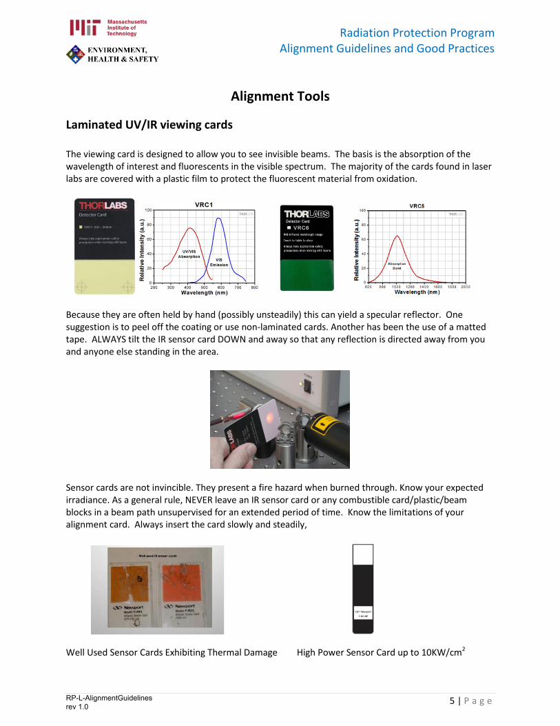
Laminated UV/IR viewing cards The viewing card is designed to allow you to see invisible beams. The basis is the absorption of the wavelength of interest and fluorescents in the visible spectrum. The majority of the cards found in laser labs are covered with a plastic film to protect the fluorescent material from oxidation.
Because they are often held by hand (possibly unsteadily) this can yield a specular reflector. One suggestion is to peel off the coating or use non-laminated cards. Another has been the use of a matted tape. ALWAYS tilt the IR sensor card DOWN and away so that any reflection is directed away from you and anyone else standing in the area.
Sensor cards are not invincible. They present a fire hazard when burned through. Know your expected irradiance. As a general rule, NEVER leave an IR sensor card or any combustible card/plastic/beam blocks in a beam path unsupervised for an extended period of time. Know the limitations of your alignment card. Always insert the card slowly and steadily,
Well Used Sensor Cards Exhibiting Thermal Damage High Power Sensor Card up to 10KW/cm2
RP-L-AlignmentGuidelines rev 1.0
Radiation Protection Program Alignment Guidelines and Good Practices
6 | P a g e
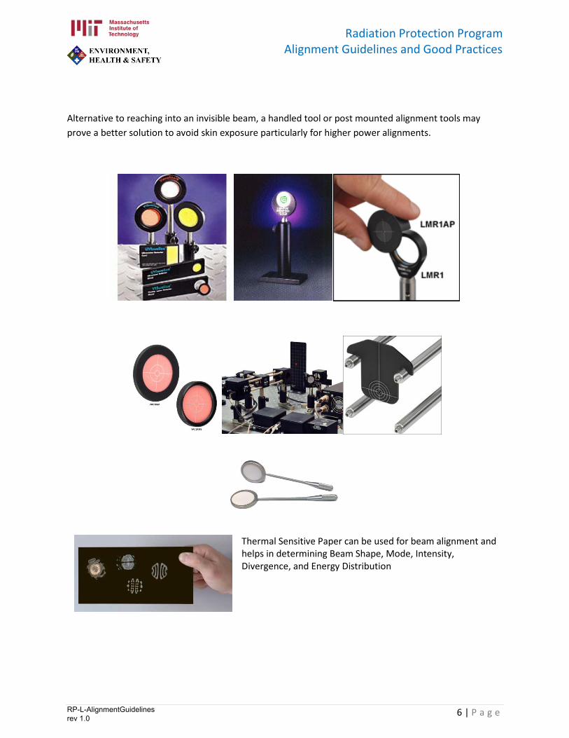
Alternative to reaching into an invisible beam, a handled tool or post mounted alignment tools may prove a better solution to avoid skin exposure particularly for higher power alignments.
Thermal Sensitive Paper can be used for beam alignment and helps in determining Beam Shape, Mode, Intensity, Divergence, and Energy Distribution
RP-L-AlignmentGuidelines rev 1.0
Radiation Protection Program Alignment Guidelines and Good Practices
7 | P a g e
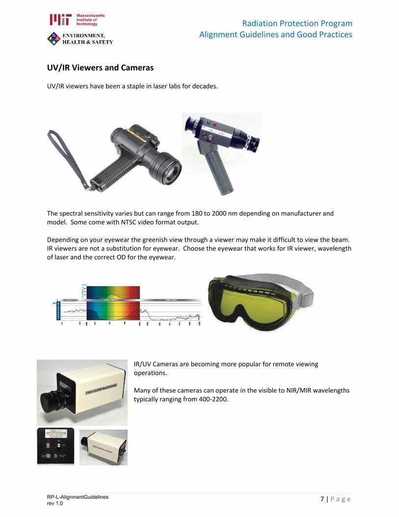
UV/IR Viewers and Cameras UV/IR viewers have been a staple in laser labs for decades.
The spectral sensitivity varies but can range from 180 to 2000 nm depending on manufacturer and model. Some come with NTSC video format output. Depending on your eyewear the greenish view through a viewer may make it difficult to view the beam. IR viewers are not a substitution for eyewear. Choose the eyewear that works for IR viewer, wavelength of laser and the correct OD for the eyewear.
IR/UV Cameras are becoming more popular for remote viewing operations. Many of these cameras can operate in the visible to NIR/MIR wavelengths typically ranging from 400-2200.
RP-L-AlignmentGuidelines rev 1.0
Radiation Protection Program Alignment Guidelines and Good Practices
8 | P a g e
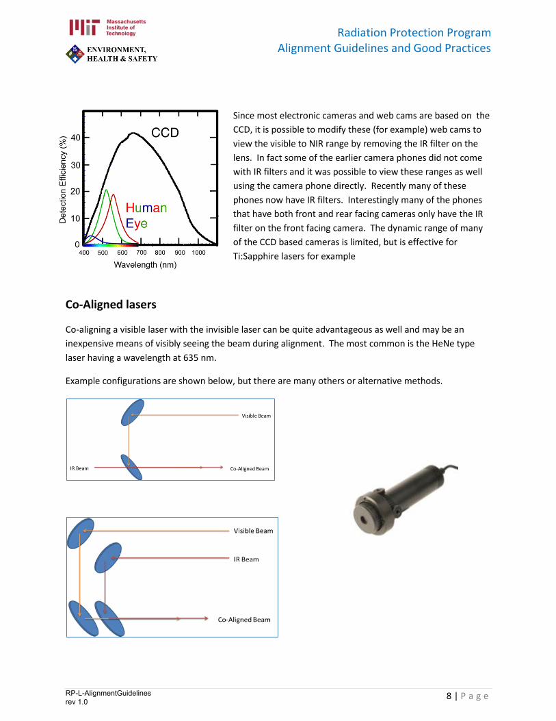
Since most electronic cameras and web cams are based on the CCD, it is possible to modify these (for example) web cams to view the visible to NIR range by removing the IR filter on the lens. In fact some of the earlier camera phones did not come with IR filters and it was possible to view these ranges as well using the camera phone directly. Recently many of these phones now have IR filters. Interestingly many of the phones that have both front and rear facing cameras only have the IR filter on the front facing camera. The dynamic range of many of the CCD based cameras is limited, but is effective for Ti:Sapphire lasers for example
Co-Aligned lasers
Co-aligning a visible laser with the invisible laser can be quite advantageous as well and may be an inexpensive means of visibly seeing the beam during alignment. The most common is the HeNe type laser having a wavelength at 635 nm.
Example configurations are shown below, but there are many others or alternative methods.
RP-L-AlignmentGuidelines rev 1.0