Embed Size (px)
Citation preview

1-S.E. Andrews 4/20/10 MIT Lincoln Laboratory
Radar Open System Architecture For Lincoln Space Surveillance
Activities Susan E. Andrews
Peter Yoho Gerald P. Banner
Thomas L. Sangiolo MIT Lincoln Laboratory
April 2010 This work is sponsored by the Air Force under A/F contract #FA8721-05-C-0002. Opinions recommendations and conclusions are those of the author and are not necessarily endorsed by the United States Air Force
2-S.E. Andrews 4/20/10 MIT Lincoln Laboratory
Definitions
• Open Systems (U.S. Department of Defense/Software Engineering Institute) [1]
“ An open system is a collection of interacting software, hardware and human components, designed to satisfy stated needs, with the interface specification of its components fully defined available to the public, maintained according to group consensus in which the implementation of components are conformant to the specification.1”
• Commercial Off The Shelf (COTS) (summary from Federal Acquisition Regulations) [2]
– Customarily used for nongovernmental purpose – Has been sold, leased or licensed to the general public – Exists a priori (in a catalogue or price list)2

3-S.E. Andrews 4/20/10 MIT Lincoln Laboratory
Outline
• Objectives & motivation • Radar Open System Architecture (ROSA) • ROSA implemented • Space surveillance challenges and
benefits • Summary
4-S.E. Andrews 4/20/10 MIT Lincoln Laboratory
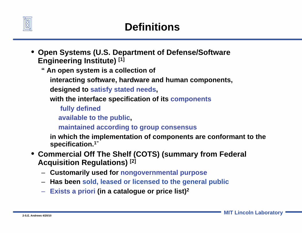
Lincoln Space Surveillance Complex Westford, Massachusetts
Millstone Haystack HAX Beamwidth (deg) 0.44 0.05 0.1 Frequency 1295 MHz 10 GHz 16.7 GHz
• Millstone – High sensitivity – Radar Cross Section
(RCS) vs Time – Small object search
• Haystack – Very high sensitivity – Range-Doppler
imaging • HAX
– High-resolution imaging
Millstone Hill Radar
Haystack Radar Haystack Auxiliary Radar
Lincoln Space Surveillance Complex (LSSC)
3 Andrews [2007]

5-S.E. Andrews 4/20/10 MIT Lincoln Laboratory
Kwajalein Missile Range
• ALTAIR [7]
– High sensitivity – Radar Cross Section (RCS)
vs Time – Primary space tracking
radar • TRADEX [8]
– Alternative space tracking radar
• ALCOR, MMW [6] – Range-Doppler imaging
TRADEX L-band, 1320 MHz S-band, 2950 MHz
ALTAIR VHF, 158 MHz / UHF, 422
MHz
MMW Ka-band, 35 GHz W-band, 95 GHz
ALCOR C-band, 5664 MHz MHMHMHMHMHMHMHMMHMHMHMMM zz zz zz z z
Space Surveillance Hub 6. Balesteri [2000]

6-S.E. Andrews 4/20/10 MIT Lincoln Laboratory
Objectives & Motivation
• Establish an open systems approach as the foundation for radar systems development in order to: – lower development time – Improve life-cycle costs – Increase systems performance
• Improve : – Portability – Interoperability – Compatibility – Reusability – Maintainability – Affordability - improve acquisition model – Scalability- quick insertion of new technology
• Develop plug-and-play radar components – Share components between DOD programs – Migrate to commercial world
4. Sangiolo [4/2001]

7-S.E. Andrews 4/20/10 MIT Lincoln Laboratory
Outline
• Objectives & motivation • Radar Open System Architecture (ROSA)
– Radar Architectures Old & New – Benefits – Example
• ROSA implemented • Space surveillance challenges and
benefits • Summary
8-S.E. Andrews 4/20/10 MIT Lincoln Laboratory
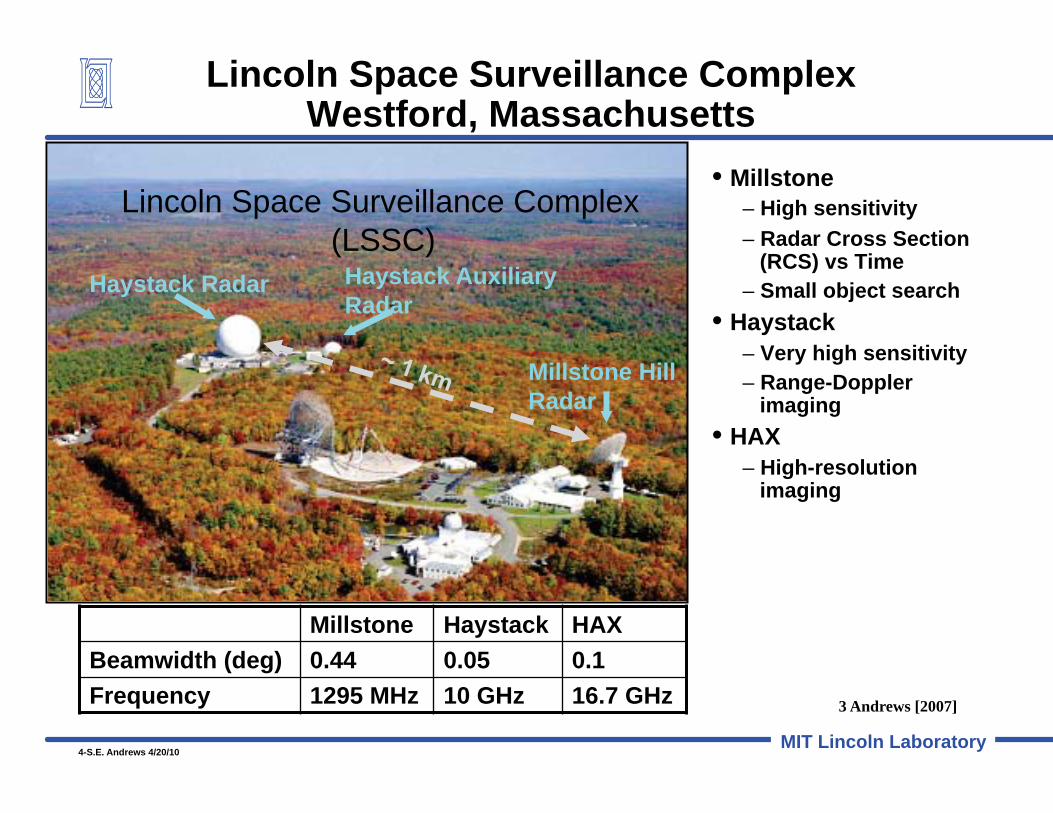
• Traditional Radar Systems Model – Master computer and centralized hardware – Custom development, proprietary HW & SW
• Open Systems Architecture – Radar functionally decomposed into building
block components – Industry standard COTS hardware and
interfaces – Components available for technology transfer
Antenna
Transmitter Recording
Antenna Transmitter Timing
es
COTS
Custom
es
Timing
Main Computer And Recording
Main Computer
Silicon Graphics
Silicon Graphics
Origin 2000
Origin 2000
Silicon Graphics
Silicon Graphics
Origin 2000
Origin 2000
Radar Architectures Old & New
4. Sangiolo [4/2001]

9-S.E. Andrews 4/20/10 MIT Lincoln Laboratory
Digital Pulse Compression RF IF
Receiver
Recording
Master T WFG Upconverter
Transmitter Transmitter
Upconverter
Digital Pulse Compression
Antenna Control
Transmitter Control
Frequency and Timing Radiation
Monitor Interface
Transmitter Control
Master Timing WFG
MIC
RO
WAV
E
Recording
Loca
l C
onso
le
Main Computer
Signature Radar
ROSA Legacy
RF IF Receiver
ROSA
ROSA Block Diagram
4. Sangiolo [4/2001]

10-S.E. Andrews 4/20/10 MIT Lincoln Laboratory
• COTS/Open Systems hardware core: – VME/VXI, PCI and other IEEE standard technology – Standard networks and interfaces
• Additional VME boards added to provide subsystem functions • POSIX-compliant operating system (POSIX, NFS, ANSI C) • Built in diagnostics provided by CPU
IRIG TOD
ENET
IRIG Network
Net CPU
PCI
Remote Development and Diagnostics
IP carrier
Power Supply Monitor
VME- BUS
Board 2 Board 1 Board N Board 3
Subsystem Dependent Boards
ROSA Generic Subsystem Example
5. Sangiolo [2000]
COTS/Common
System Specific
11-S.E. Andrews 4/20/10 MIT Lincoln Laboratory
Outline
• Objectives & motivation • Radar Open System Architecture (ROSA) • ROSA implemented • Space surveillance challenges and
benefits • Summary

12-S.E. Andrews 4/20/10 MIT Lincoln Laboratory
-
-
-
-
-
New common radar system
• 80% Reduction in custom hardware
> 85 % COTS Seven custom boards for all Radars 70% reduction in number of racks
• Automated and remote operations/diagnostics
• Dramatic improvement in flexibility
Kwajalein Radar Modernization
4. Sangiolo [4/2001]

13-S.E. Andrews 4/20/10 MIT Lincoln Laboratory
Digital Pulse Compression RF IF
Receiver
Recording
Master T WFG Upconverter
Transmitter Transmitter
Upconverter
Digital Pulse Compression
Antenna Control
Transmitter Control
Frequency and Timing Radiation
Monitor Interface
Transmitter Control
Master Timing WFG
MIC
RO
WAV
E
Recording
Loca
l C
onso
le
Main Computer
RF IF Receiver
• Common radar software for all radars – 70% reduction in lines of code – 85% reduction in languages/OS/Platforms
• Extensive capability – >150 waveforms supported – 16 Channel coherent integration and detection – Multi-Target-Tracking (64 targets) – Bayesian Classifier (WB features) – Automated script-driven operations – Space surveillance functions – Common data recording format (> 80 Mbytes/sec) – Full PRI rate digital simulation
64 targets and simulated targets over live data
New Software
ALCOR SGI
MMW Modcomp
ALTAIR Vax
TDX Gould
Existing Software
Radar SGI
Hay/Hax SGI
MHR Harris x x x
ar
Main Computer Real Time Program (RTP)
4. Sangiolo [4/2001]

14-S.E. Andrews 4/20/10 MIT Lincoln Laboratory
Radar Open Systems Architecture - ROSA Benefits
• Reduced development time and operations and maintenance cost • Decomposition provides efficient use of engineering resources
– Allows many small development teams (distributed locations) – Concurrent integration, test and evaluation
• Components easily added, shared and modified – Migration to new technology can be done at the unit level
• New developments can begin with working components – Better acquisition model, reduced non-recovered engineering costs
• Subsystems encapsulate specific radar function – Underlying hardware and software is hidden
• Communication is key to architecture – Subsystem components completely define their functionality and
interfaces to the outside world
MAIN COMPUTER SUBSYSTEM
Control Message
Control message
LOCAL
SYSTEM
Silicon Graphics
Silicon Graphics
Origin 2000
Origin 2000
Development and local operations Full radar operation
4. Sangiolo [4/2001]

15-S.E. Andrews 4/20/10 MIT Lincoln Laboratory
Outline
• Objectives & motivation • Radar Open System Architecture (ROSA) • ROSA implemented • Space surveillance challenges and
benefits • Summary

16-S.E. Andrews 4/20/10 MIT Lincoln Laboratory
ROSA Development Significant to Space Surveillance
• Debris Mode – Stare at Fixed Azimuth and Elevations and detect and record
debris objects as they go through beam • Trajectory Scans (α/β Scan) & (Progressive α/β Scan)
– Scans along satellite trajectory in time and orthogonal by beam width
• Satellite Tracking Displays – Simplified Displays for Satellite Tracking
• Selective Radar Channel Recording – Ability to record selective Radar Channel data (PP; PP/OP or all
four channels) • Deep Space Tracking (MHR SATCIT)
– Integrate SATCIT on MHR and then HAY and HAX radars • Wideband Network Sensors (WNS)
– High speed network demonstration with Radar Data >1gbit/sec
4. Sangiolo [4/2001]

17-S.E. Andrews 4/20/10 MIT Lincoln Laboratory
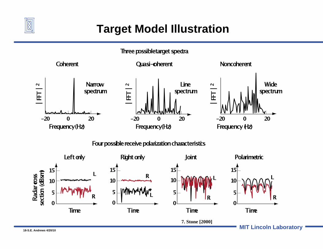
Deep Space Tracking Operations – Real time Multi-pulse Integration
• 30+ year history of deep space* tracking operations [7]
– 1963 - Detected Syncom II in GEO using post-processing – 1965 – Real-time computer enables rudimentary multi-
pulse processing in real time – 1971 – Experiments using Haystack planetary radar to
observe GEO satellites – 1975 – Millstone begins routine operations tracking deep
space objects for U.S. Space Surveillance Network • Acquisition and tracking process [7,9]
– Operate beyond unambiguous range of radar – Order of 1000 pulses integrated to gain 30 dB – 12 classes target models processed simultaneously
3 levels of coherence 4 options for polarization of returns Best model selected in real time
TRADEX ALTAIR
HAY/HAX
MILLSTONE
* Deep Space orbits here are defined to be those with periods > 225 minutes
18-S.E. Andrews 4/20/10 MIT Lincoln Laboratory
Target Model Illustration
7. Stone [2000]

19-S.E. Andrews 4/20/10 MIT Lincoln Laboratory
HAX/HAY ROSA WNS Block Diagram
4. Sangiolo [4/2001]
MIC
RO
WAV
E M
ICR
OW
AVE
Transmitter
Receiver
MIC
RO
WAV
E
Transmitter
Receiver

20-S.E. Andrews 4/20/10 MIT Lincoln Laboratory
Remote Operations – Lincoln Space Situational Awareness Center
• Joint control room for shared site – Operators can view other sensor activities real-time – Direct communications among sensor operators – Cross-sensor familiarity
• Remote viewing of second shared site – Real-time viewing of sensor activities and cross-sensor familiarity – Best possible planning time
• Joint control room for multiple sites (notional)
3. Andrews, S.E., et al [2007]
21-S.E. Andrews 4/20/10 MIT Lincoln Laboratory
Summary
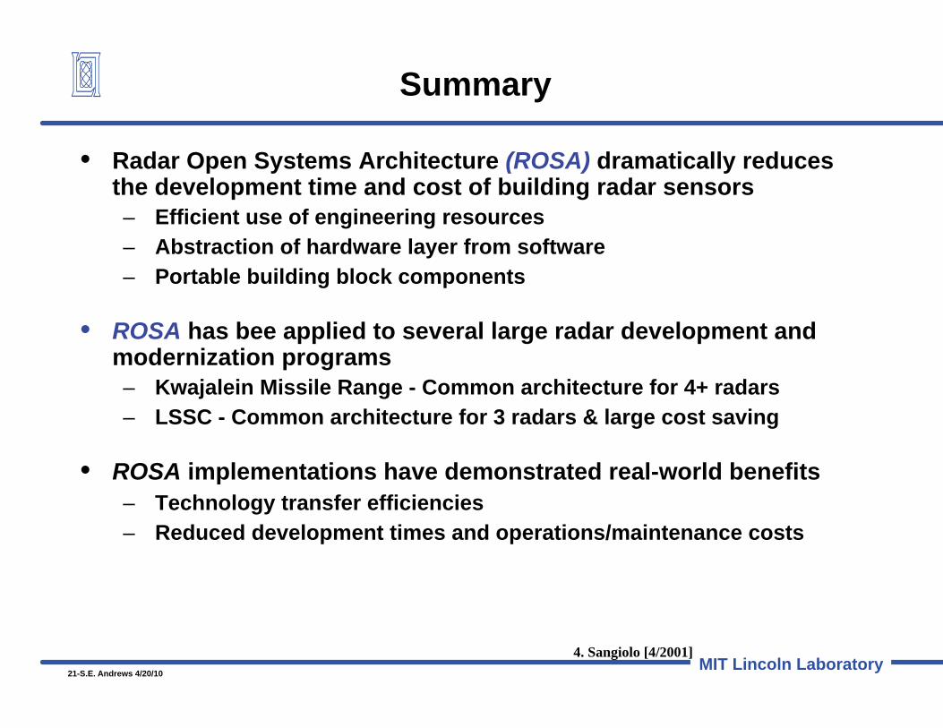
• Radar Open Systems Architecture (ROSA) dramatically reduces the development time and cost of building radar sensors – Efficient use of engineering resources – Abstraction of hardware layer from software – Portable building block components
• ROSA has bee applied to several large radar development and modernization programs – Kwajalein Missile Range - Common architecture for 4+ radars – LSSC - Common architecture for 3 radars & large cost saving
• ROSA implementations have demonstrated real-world benefits – Technology transfer efficiencies – Reduced development times and operations/maintenance costs
4. Sangiolo [4/2001]

22-S.E. Andrews 4/20/10 MIT Lincoln Laboratory
Bibliography
1. Software Engineering Institute, Carnegie Mellon Institute, 2009, http://www.sei.cmu.edu/opensystems/
2. Federal Acquisition Regulation, General Services Administration http://www.acquisition.gov/far/current/html/Subpart%202_1.html#wp1145507, 17 Feb 2009.
3. Andrews, S.E., Bougas, W. C., Cott, T.A., Hunt, S. M., Kadish, J.M., Solodyna, C.V., “Enhancing Multi-payload Launch Support with Netcentric Operations”, 7th US/Russian Space Surveillance Workshop, October 29 – November 2, 2007 (MS-29216)
4. Sangiolo, Thomas L., “Radar Open System Architecture For The Lincoln Space Surveillance Complex (LSSC)”, Proceedings of the 2001 Space Control Conference, MIT Lincoln Laboratory, 3-5 April, 2001, STK-256, S.E. Andrews Ed (MSJA-14085, 14085A, charts and paper)
5. Sangiolo, Thomas L., “Radar Open System Architecture For The Lincoln Space Surveillance Complex (LSSC)”, Proceedings of the 2000 Space Control Conference, MIT Lincoln Laboratory, 11-13 April, 2000, STK-255, S.E. Andrews Ed (MSJA-14085, charts and paper)
6. Balesteri, D., Baldassini, J., DeCoster, W., Hogan, G., Hunt, S., Lazdowski, K., and Mathwig, J. “Kwajalein Space Surveillance Center (KSSC), 2000 Space Control Conference, MIT Lincoln Laboratory, 12 April 2000 (MS-14184)
7. Stone, M.L. and Banner, G.P, Radars for the Detection and Tracking of Ballistic Missiles, Satellites, and Planets, Lincoln Laboratory Journal, pp 217-244, Vol 12, Number 2, 2000
8. Camp, W.W., Mayhan, J.T. and O’Donnell, R. M., “Wideband Radar for Ballistic Missile Defense and Range-Doppler Imaging of Satellites” Lincoln Laboratory Journal, pp 267-280, Vol 12, Number 2, 2000
9. Banner, G.P. “Deep space surveillance – overview and radar tracking”, 3rd US/Russian Space Surveillance Workshop, 20-23 October 1998, (MS-13301)

23-S.E. Andrews 4/20/10 MIT Lincoln Laboratory
TRADEX ALTAIR MMW ALCOR HAY/HAX MILLSTONE
FREQUENCY (GHz) 100 10 1
W K a S L UHF VHF
Freq.
Band
0.1
K u X L UHF
C
Lincoln Laboratory Space Surveillance Radars
Frequency Bands
4. Sangiolo [4/2001]