Embed Size (px)
Citation preview

1
Rada 215Installation and Maintenance
Water Temperature Controls Single Point of Use
Thermostatic
This Rada 215 Valve has been supplied for this application based upon information provided to Armstrong at the time the order was placed.
This Rada 215 Valve is configured for use in a “dead-leg” piping configuration as indicated in the drawing on Page 4.
This Rada 215 Valve has not been designed to deliver tepid water to Emergency Fixtures.
For further information, please call our technical department Toll Free at 1-888-HOT-HOSE.
Model No. Rada 215
Serial No.
Ship Date:
ASSE 1069
CSA B125
ALIB-215-A

2
Water Temperature Control - Single Point of Use
CDLW
1057
Thermostatic Rada 215Rada Thermostatic Mixing Valve of “sealed for life” replaceable cartridge construction. Compact design is ideally suited for use at or near the final point of use to deliver a pre designated mixed water temperature to either a single or a small “group” of lavatories.
Complete operating mechanism is enclosed in a durable disposable polymer cartridge for ease of maintenance. Powerful internal movement of the hot and cold water proportioning mechanism resists mineral deposition.
Capable of close temperature control at diverse flow rates between .5 and 11 gpm (1.9 and 41.6 lpm). Unit is supplied as standard with a tamperproof single temperature “locking” shroud and variable temperature control trim set.*
* Use of the trim set allows for full temperature control to within 5°F (2°C) of either inlet supply along with an integral maximum temperature limit stop and single temperature locking option.
Operational Specifications• Typical outlet temperature control +/-2°F• Adjustable maximum temperature limit stop• Adjustable single temperature locking option• Thermal shutdown mode upon inlet supply failure
Technical Specifications• 1/2” NPT inlets and 1/2” NPT outlet• Chrome plated DZR brass/stainless alloy/polymer
construction• Operating pressures
Maximum: 150 psi (10 bar) Minimum: 10 psi (.7 bar)
• Integral inlet check valves and strainers• ASSE 1069 Certified• Shipping weight 10 lbs (4.5 kg)
For a submittal, refer to D32599.
Rada Thermostatic Mixing Valves (gpm)
ModelPressure Drop (psi)
Min. Flow CV5 10 15 20 25 30 35 40 45 50
215 4 5 7 8 9 9 10 11 11 12 .5 1.7

3
Safety Warnings
The function of a Thermostatic Mixing Valve is to deliver water consistently at a pre-designated temperature.Rada Thermostatic Mixing Valves are precision engineered to give continued superior and safe performanceprovided:
1. They are installed, commissioned, operated and maintained in accordance with the recommendations provided and accepted plumbing practices.
2. Periodic attention is given, as necessary, to maintain the product, the accessory fittings and the plumbing system in good functional order.
In keeping with every other mechanical product, Rada Mixing Valves should not be considered as functionally infallible and, as such will never totally replace the vigilance and attention of facility nursing/bathing or other institutional supervisory or industrial safety staff.
Provided that they are installed, commissioned, operated and maintained, the risk of product failure and its associated consequences, if not eliminated, are reduced to the minimum achievable.
Rada 215 Operating Specifications
Maximum Hot Water Supply Temperature 180°F (82°C)
Minimum Cold Water Supply Temperature 39°F (4°C)
Minimum Cold Water Supply Temperature Range 39°F to 80°F (4°C to 27°C)
Optimum Inlet to Outlet Temperature Differential 21°F (12°C)
Optimum Thermostatic Control Range 86°F (30°C) - 122°F (50°C)
Maximum Flow Rate at 45 psi 11 gpm (42 lpm)
Maximum Flow Rate at 9’ per second 5.6 gpm (21 lpm)
Minimum Flow Rate .5 gpm (2 lpm)
Maximum Inlet Supply Pressure 150 psi (10 bar)
Minimum Inlet Supply Pressure 10 psi (0.7 bar)
* Rada 215 can accept temporary excursions above 180°F (82°C) and maintain control without sustaining internal damage. Prolonged operation of the Mixing Valve at such elevated temperatures is not recommended.
** Under laboratory test conditions Rada 215 has displayed a repeatable capability to blend to within 5°F (2°C) of each inlet supply temperature. 21°F (12°C) is the optimum published differential required to achieve full thermal performance.

4
Rada 215 Installation
The Rada 215 Thermostatic Mixing Valve must be installed as per the piping schematic provided below.
Failure to follow this directive will compromise valve/system performance, void all warranties and may create a user comfort issue and safety concern.
Armstrong has Technical Support personnel available from 8:00 a.m. to 5:00 p.m. EST. Call Toll Free 1-888-HOT HOSE.
Notes:1. Rada 215 may be installed in a vertical or horizontal position.
2. Rada 215 is designed to be piped in a standard HOT-LEFT/COLD-RIGHT inlet supply configuration. There are red (hot) and blue (cold) markings on each valve. Rada 215 is provided as standard with ½” NPT inlet connections and a rear facing ½” NPT outlet connection.
The inlet supplies must always match the corresponding inlet ports on the valve.
3. The installation of flat faced union connections at each inlet and the outlet as close to the mixing valve as feasible is recommended to facilitate check valve and inlet strainer screen service and replacement.
4. Be sure to thoroughly flush the pipe work before fitting the Rada 215.
5. Be sure to “make up” all “sweat” or “soldered” fittings ahead of time. Do not expose Rada 215 or any of its fittings to extreme temperatures (such as an acetylene or propane torch).
6. Rada 215 is serviced from the front of the valve as you face it. A minimum 12” clearance in front of the Temperature Control Handle is suggested for internal parts access.
7. Rada 215 is pre-set and locked at the factory to a fixed outlet temperature of 110°F (43°C). It is highly unlikely that the installation site conditions will match the test conditions. As such:
RADA 215 MUST BE RE-SET ON SITE BY QUALIFIED PERSONNEL.
NOTE: In the event that the inlet supplies are reversed, the cartridge inside the Rada 215 can be rotated 180° to correct. Refer to Page 7 “Servicing & Maintenance” for cartridge access directives.
Rada 215 is supplied with integral check valves and strainer screens. Check valves and strainers indicated on drawing above are an optional recommendation.

5
Rada 215 Commissioning
Commissioning must be carried out in accordance with these instructions, and must be conducted by designated, qualified and competent personnel.
Rada 215 is fully performance tested and the maximum temperature is pre-set to approximately 110°F (43°C) under ideal installation conditions at the factory.
Site conditions and design preference may dictate that the maximum temperature has to be re-set following installation.
Rada 215 is supplied as standard with a tamper proof polymer Locking Cap (D33333).
Rada 215 is supplied with an optional Temperature Knob Assembly (D32627) which is packaged separately.
Setting the Temperature-Locking Cap
To set temperature the Locking Cap must first be removed using a 3mm hex wrench.
Ensure that the hot and cold supplies are at their designated pressures and temperatures. Open mixed water outlet(s) and wait until the hot and cold inlet temperatures are stable. Note the mixed water temperature. If the mixed water temperature requires adjustment proceed as follows.
1. Remove the tamper proof Locking Cap using a 3mm hex wrench.
2. Remove the temperature Hub (D33331) by pulling it towards you.
3. Rotate the spindle until the desired temperature is obtained at the discharge point (clockwise = decrease temperature, counterclockwise = increase temperature). NOTE: for additional leverage place the temperature Hub back on the spindle ensuring that it remains raised above the two stops on the cartridge face.
There will be slight resistance as the valve internal proportioning mechanism engages as the spindle rotates from cold to hot. This is normal BUT any resistance encountered at full rotation (full hot/full cold) must not be overcome with force otherwise internal parts damage may result.
4. Once the desired temperature has been achieved re-fit the Hub without disturbing the spindle so that the nub on the bottom of the Hub seats in between the two stops on the valve body preventing further rotation in either direction.
5. Fit the Locking Cap back onto the valve and secure with the 3mm screw.
Setting the Temperature-Temperature Knob
When the Temperature Knob is deployed the Rada 215 can either be set to a desired single temperature and locked so that there is no temperature adjustment capability by the user OR set with a Maximum Temperature stop which allows user temperature adjustment at temperatures below the Maximum Temperature setting.
To set and lock the Rada 215 at a single temperature follow directives 1-4 above and then follow directive 7 on page 6.
To set a Maximum Temperature stop which allows user temperature adjustment at temperatures below the Maximum Temperature setting follow directives 1-7 on page 6.

6
Setting the Temperature-Temperature Knob - continued
Ensure that the hot and cold supplies are at their designated pressures and temperatures. Open mixed water outlet(s) and wait until the hot and cold inlet temperatures are stable. Note the mixed water temperature. If the mixed water temperature requires adjustment proceed as follows.
1. Remove the tamper proof Locking Cap using a 3mm hex wrench.
2. Remove the temperature Hub (D33331) by pulling it towards you.
3. Rotate the spindle until the desired temperature is obtained at the discharge point (clockwise = decrease temperature, counterclockwise = increase temperature). NOTE: for additional leverage place the temperature Hub back on the spindle ensuring that it remains raised above the two stops on the valve body.
There will be slight resistance as the valve internal proportioning mechanism engages as the spindle rotates from cold to hot. This is normal BUT any resistance encountered at full rotation (full hot/full cold) must not be overcome with force otherwise internal parts damage may result.
4. Once the desired temperature has been achieved, refit the hub without disturbing the spindle, positioning the hub such that the lug is against the side of the stop on the cartridge face, thus preventing counterclockwise rotation.
5. Check that the water temperature has not been altered.
6. As a final check rotate the hub fully clockwise so that the water temperature drops and then rotate it back counter clockwise to the stop. Allow water temperature to stabilize and check that the desired Maximum Temperature stop has been accurately set.
7. Re-fit the Temperature Knob so that the indicator on the knob is aligned to the left of the red markings (approximately at 9 O’clock) and secure with the 3 mm hex screw.
Figure 6-1
7
Rada 215 Servicing and Maintenance
Rada 215 Thermostatic Mixing Valves should be inspected annually, or more frequently where acknowledged site conditions such as high mineral content water dictate.
Rada 320 Thermostatic Mixing Valve is of non-serviceable single “cartridge construction”. The cartridge (Fig 7.2) can be removed from the valve for inspection or replacement.
Before proceeding further be sure to isolate the valve by turning off each inlet supply.
Cartridge removal
1. Remove the tamper proof Locking Cap using a 3mm hex wrench.
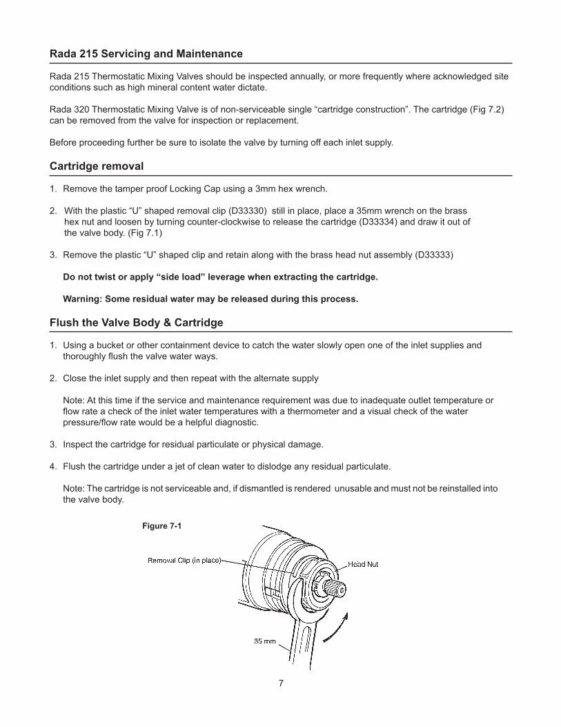
2. With the plastic “U” shaped removal clip (D33330) still in place, place a 35mm wrench on the brass hex nut and loosen by turning counter-clockwise to release the cartridge (D33334) and draw it out of the valve body. (Fig 7.1)
3. Remove the plastic “U” shaped clip and retain along with the brass head nut assembly (D33333)
Do not twist or apply “side load” leverage when extracting the cartridge.
Warning: Some residual water may be released during this process.
Flush the Valve Body & Cartridge
1. Using a bucket or other containment device to catch the water slowly open one of the inlet supplies and thoroughly flush the valve water ways.
2. Close the inlet supply and then repeat with the alternate supply
Note: At this time if the service and maintenance requirement was due to inadequate outlet temperature or flow rate a check of the inlet water temperatures with a thermometer and a visual check of the water pressure/flow rate would be a helpful diagnostic.
3. Inspect the cartridge for residual particulate or physical damage.
4. Flush the cartridge under a jet of clean water to dislodge any residual particulate.
Note: The cartridge is not serviceable and, if dismantled is rendered unusable and must not be reinstalled into the valve body.
Figure 7-1

8
Cartridge Replacement
1. Insert the cartridge into the Brass Head Nut assembly and re-fit the plastic “U” shaped clip.
2. Lubricate the “racetrack” shaped Inlet Seals using only a silicone based lubricant.
3. Identify the hot inlet and cold inlet on the valve body (if not readily identifiable, consider repeating the flushing process suggested above) and align the cartridge (note red and blue location lugs per Figure 8-1) accordingly.
4. Carefully push the cartridge into the valve body ensuring that the “racetrack” inlet port seals remain in place.
5. Align and then tighten the Brass Head Nut assembly using care not to over torque.
6. Fit the Locking Cap back onto the valve and secure with the 3mm screw.
NOTE: The Rada 215 installation recommendation is to pipe the mixing valve with the Hot Water supply on the left (9 O’clock) and the Cold Water supply on the right (3 O’clock). In the event these supplies are reversed the cartridge can be rotated 180 degrees to correct. The colored tab on the cartridge must always correspond with the appropriate inlet supply (red = hot, blue = cold)
Figure 8-1

9
Rada 215 Servicing and Maintenance
Inlet Check ValvesHot Water entering the cold supply or vice-versa indicates that immediate attention is required. Thus is best accomplished by removing and cleaning or removing and replacing the two inlet check valves (Figure 9-1)
Before proceeding further be sure to isolate the valve by turning off each inlet supply.
1. Release the 215 Mixing Valve from the pipe work at the flat faced unions (suggested in the installation sequence on page 4.
2. Remove the Check Valve (D33335) from the valve body using a suitably sized or adjustable wrench.
3. Remove the strainer.
4. Inspect the cartridge for residual particulate or physical damage.
5. Flush the cartridge under a jet of clean water to dislodge any residual particulate.
6. The Check Valve contains no user serviceable replacement parts.
7. Replace the strainer and lubricate/replace the inlet seal.
8. Replace the Check Valve into the Mixing Valve body and then refit the Mixing Valve into the pipe work.
Spare Parts
Part Number DescriptionD33330 Removal ClipD33331 Hub, BlackD33332 Locking CapD33333 Head NutD33334 Radatherm Cartridge AssemblyD33335 Check Valve Cartridge - NPTD32686 Temperature Knob Assembly, ChromeD32627 Temperature Knob Assembly, WhiteD33336 Service/Strainer Pack*D33337 Outlet Adapter - NPT
Figure 9-1
Figure 9-2

10
Troubleshooting
Problem Solution
1. Only hot or cold water from inlet a. Inlet supplies reversed (i.e. hot supply to cold inlet). Check.b. Not hot water reaching mixing valve. Check.c. Check strainers and inlet/outlet fittings for blockage.d. Refer to symptom 5 below.e. Installation conditions continuously outside operating parameters: refer to Specification and 2e below.
2. Fluctuating or reduced flow rate Normal function of mixing valve when operating conditions are unsatisfactory.
a. Check strainers and inlet/outlet fittings for flow restriction.b. Assure that minimum flow rate is sufficient for supply conditions.c. Assure that dynamic inlet pressures are nominally balanced.d. Assure that inlet temperature differentials are sufficient.e. (subsequent to rectification of supply conditions) Check thermostatic performance; renew Radatherm cartridge if necessary.
3. No flow from mixing valve outlet a. Check strainers and inlet/outlet fittings for blockageb. Hot or cold supply failure; thermostat holding correct shut-down function: rectify, and return to 2e above.
4. Blend temperature drift Indicated operating conditions changed.
a. Refer to problem 2 above.b. Hot supply temperature fluctuation.c. Supply pressure fluctuation.
5. Hot water in cold supply or cold water in hot supply
Indicates check valves require maintenance, refer to Maintenance.
6. Maximum blend temperature setting too hot or too cool
a. Indicates incorrect maximum temperature setting; refer to Commissioning.b. As problem 4 above.c. As problem 5 above.
7. Water leaking from valve body Seal(s) worn or damaged.
Obtain Service Pack (D33336), and replace all seals.If leak persists from around temperature spindle, renew Radatherm cartridge.

11
Notes

12
Designs, materials, weights and performance ratings are approximate and subject to change without notice.Visit armstronginternational.com for up-to-date information.
Armstrong International221 Armstrong Blvd., Three Rivers, Michigan 49093 - USAPh: (269) 279-3602 Toll Free: (888) HOT-HOSE (468-4673) Fax: (269) 279-3130
ALIB-215-ARada 215
Printed in U.S.A. - 5/12© 2012 Armstrong International, Inc.
Limited Warranty and RemedyArmstrong Hot Water Group, Inc. (“Armstrong”) warrants to the original user of those products supplied by it and used in the service and in the manner for which they are intended, that such products shall be free from defects in material and workmanship for a period of one (1) year from the date of installation, but not longer than 15 months from the date of shipment from the factory [unless a Special Warranty Period applies, as listed below]. This warranty does not extend to any product that has been subject to misuse, neglect, or alteration after shipment from the Armstrong factory. Except as may be expressly provided in a written agreement between Armstrong and the user, which is signed by both parties, Armstrong DOES NOT MAKE ANY OTHER REPRESENTATIONS OR WARRANTIES, EXPRESS OR IMPLIED, INCLUDING, BUT NOT LIMITED TO, ANY IMPLIED WARRANTY OF MERCHANTABILITY OR ANY IMPLIED WARRANTY OF FITNESS FOR A PARTICULAR PURPOSE. The sole and exclusive remedy with respect to the above limited warranty or with respect to any other claim relating to the products or to defects or any condition or use of the products supplied by Armstrong, however caused, and whether such claim is based upon warranty, contract, negligence, strict liability, or any other basis or theory, is limited to Armstrong’s repair or replacement of the part or product, excluding any labor or any other cost to remove or install said part or product, or, at Armstrong’s option, to repayment of the purchase price. As a condition of enforcing any rights or remedies relating to Armstrong products, notice of any warranty or other claim relating to the products must be given in writing to Armstrong: (i) within 30 days of last day of the applicable warranty period, or (ii) within 30 days of the date of the manifestation of the condition or occurrence giving rise to the claim, whichever is earlier. IN NO EVENT SHALL ARMSTRONG BE LIABLE FOR SPECIAL, DIRECT, INDIRECT, INCIDENTAL OR CONSEQUENTIAL DAMAGES, INCLUDING, BUT NOT LIMITED TO, LOSS OF USE OR PROFITS OR INTERRUPTION OF BUSINESS. The Limited Warranty and Remedy terms herein apply notwithstanding any contrary terms in any purchase order or form submitted or issued by any user, purchaser, or third party and all such contrary terms shall be deemed rejected by Armstrong.