Embed Size (px)
Citation preview

Code No: 123AC
JAWAHARLAL NEHRU TECHNOLOGICAL UNIVERSITY HYDERABAD B.Tech II Year I Semester Examinations, March - 2017
MECHANICS OF SOLIDS (Common to ME, MCT, MMT, AE, AME, MSNT)
Time: 3 Hours Max. Marks: 75
Note: This question paper contains two parts A and B.
Part A is compulsory which carries 25 marks. Answer all questions in Part A.
Part B consists of 5 Units. Answer any one full question from each unit.
Each question carries 10 marks and may have a, b, c as sub questions.
PART- A
(25 Marks)
1.a) How shear deformation takes place. [2]
b) Differentiate compressive and crushing stress. [3]
c) What is the procedure adopted for calculating the shear force at a section. [2]
d) In which case, the SFD is parabolic and BMD is cubic. [3]
e) What is the section modulus of a rectangular and circular sections? [2]
f) How the section modulus of a triangular section can be increased. [3]
g) What are the various forces by which the mohr’s circle is drawn. [2]
h) What is the importance of Von Misses Theory? [3]
i) What is the torsion of a tapering shaft? [2]
j) How the cylinders are classified under thin and thick sections? [3]
PART-B
(50 arks)
2. In a triaxial stress system, the six components of the stress at a point are :
σxx=6 MPa, σyy=5 MPa σzz= 4 MPa
τxy= τyx=1 MPa,, τyz= τzy= 3MPa, τzx=τxz=2 MPa.
Find the magnitude of the three principal stresses. [10]
OR
3. A hollow right circular cylinder is made of cast iron and has an outside diameter
of 75 mm and an inside diameter of 60 mm. if the cylinder is loaded by an axial
compressive force of 50 KN, determine the total shortening in a 600 mm length.
Also determine the normal stress under this load. Take the modulus of elasticity to
be 100 GPa and neglect any possibility of lateral buckling factor of the cylinder.
[10]
4. A cantilever beam loaded by a concentrated load at the free end together with a
uniform load distributed over the right half of the beam. Plot the shear and
moment diagrams shown in figure 1. [10]
Figure: 1
R15
www.ManaResults.co.in
OR
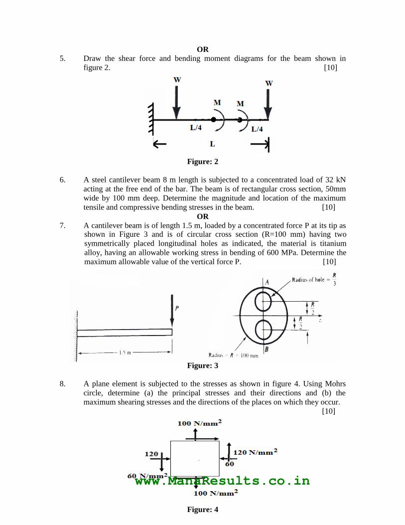
5. Draw the shear force and bending moment diagrams for the beam shown in
figure 2. [10]
Figure: 2
6. A steel cantilever beam 8 m length is subjected to a concentrated load of 32 kN
acting at the free end of the bar. The beam is of rectangular cross section, 50mm
wide by 100 mm deep. Determine the magnitude and location of the maximum
tensile and compressive bending stresses in the beam. [10]
OR
7. A cantilever beam is of length 1.5 m, loaded by a concentrated force P at its tip as shown in Figure 3 and is of circular cross section (R=100 mm) having two
symmetrically placed longitudinal holes as indicated, the material is titanium
alloy, having an allowable working stress in bending of 600 MPa. Determine the
maximum allowable value of the vertical force P. [10]
Figure: 3
8. A plane element is subjected to the stresses as shown in figure 4. Using Mohrs
circle, determine (a) the principal stresses and their directions and (b) the
maximum shearing stresses and the directions of the places on which they occur.
[10]
Figure: 4
www.ManaResults.co.in

JJ
JJ
JJ
JJ
JJ
JJ
OR
9. Discuss and derive the condition for theories of failure under Maximum shear
stress and maximum principal strain theory. [10]
10. A stepped shaft has the appearance as shown in Figure 5. The region AB is
al2014-T6 alloy. Having G=28 GPa, and the region BC is steel, having G=84
GPa. The aluminium potion is of solid circular cross section 45 mm in diameter,
and the steel region is circular of 60 mm outside diameter and 30 mm inside
diameter. Determine the peak shearing stress in each material as well as the angle
of twist at B where a torsional load of 4000 Nm is applied. Ends A & C are
rigidly clamped. [10]
Figure: 5
OR
11. A spherical tank for storing gas under pressure is 25 mm in diameter and is made of structural steel 15 mm thick. The yield point of the material is 250 MPa and a
safety factor of 2.5 is adequate. Determine the maximum permissible internal
pressure, assuming the welded seams between the various plates are as strong as
the solid metal. Also, determine the permissible pressure if the seams are 75 % as
strong as the solid metal. [10]
---ooOoo---
www.ManaResults.co.in