Embed Size (px)
Citation preview

Quenching of magnetic excitations in single adsorbates at surfaces: Mn on CuN/Cu(100)
Frederico D. Novaes,1 Nicolás Lorente,2 and Jean-Pierre Gauyacq3,4
1Institut de Ciència de Materials de Barcelona, CSIC, Campus de la UAB, E-08193 Bellaterra, Spain2Centre d’Investigació en Nanociència i Nanotecnologia, CSIC-ICN, Campus de la UAB, E-08193 Bellaterra, Spain
3CNRS, Institut des Sciences Moléculaires d’Orsay (ISMO), Unité de Recherches CNRS-Université Paris-Sud, UMR 8214,Bâtiment 351, Université Paris-Sud, 91405 Orsay Cedex, France
4Université Paris-Sud, Institut des Sciences Moléculaires d’Orsay (ISMO), Unité de Recherches CNRS-Université Paris-Sud UMR 8214,Bâtiment 351, Université Paris-Sud, 91405 Orsay Cedex, France
�Received 29 June 2010; revised manuscript received 7 September 2010; published 1 October 2010�
The lifetimes of spin excitations of Mn adsorbates on CuN/Cu�100� are computed from first principles. Thetheory is based on a strong-coupling approach that evaluates the decay of a spin excitation due to electron-holepair creation. Using a previously developed theory �Phys. Rev. Lett. 103, 176601 �2009� and Phys. Rev. B 81,165423 �2010��, we compute the excitation rates by a tunneling current for all the Mn spin states. A rateequation approach permits us to simulate the experimental results by Loth and co-workers �Nat. Phys. 6, 340�2010�� for large tunneling currents, taking into account the finite population of excited states. Our simulationsgive us insight into the spin dynamics, in particular, in the way polarized electrons can reveal the existence ofan excited-state population. In addition, it reveals that the excitation process occurs in a way very differentfrom the deexcitation one. Indeed, while excitation by tunneling electrons proceeds via the s and p electrons ofthe adsorbate, deexcitation mainly involves the d electrons.
DOI: 10.1103/PhysRevB.82.155401 PACS number�s�: 68.37.Ef, 72.10.�d, 73.23.�b, 72.25.�b
I. INTRODUCTION
Recently, a series of experimental studies1–6 with low-temperature scanning tunneling microscope �STM� revealedthat isolated adsorbates on a surface could exhibit a magneticstructure, i.e., that a local spin could be attributed to theadsorbate. Interaction of this local spin with its environmentresults in several magnetic energy levels that correspond todifferent orientations of the local spin relative to the sub-strate. A magnetic field, B, was also applied to the system:increasing the B field decouples the local spin from its envi-ronment and the system switches to a Zeeman structure, thushelping to characterize the adsorbate magnetic anisotropy.The energy of the various magnetic levels were obtained viaa low-temperature inelastic electron tunneling spectroscopy�low-T IETS� experiment, in which the tip-adsorbate junc-tion conductivity as a function of the STM bias exhibits stepsat the magnetic excitation thresholds. The magnetic excita-tion energies are small, typically in the few milli-electronvoltrange. Besides the spectroscopy properties, the IETS experi-ments also revealed that the conductance steps at the mag-netic inelastic thresholds are very high, i.e., that the effi-ciency of the tunneling electrons in inducing magnetictransitions in the adsorbate is extremely large. In metal-phthalocyanine adsorbates, for example,3,4 the tunneling cur-rent is dominated by its inelastic component when the bias isabove the magnetic excitation thresholds. This efficiency isat variance with the efficiency of tunneling electrons in ex-citing vibrational modes in a molecular adsorbate which wasobserved and shown to only reach the few percent range.7–9
Several theoretical accounts of the magnetic excitation pro-cess have been reported.2,10–12 A strong-couplingapproach13,14 of this problem was also introduced that quan-titatively accounted for the very large efficiency of tunnelingelectrons in inducing magnetic transitions.13,14 An analysis of
the magnetic excitation processes in these systems in termsof spin-transfer torque has been presented by Delgado et al.15
These systems present rich physics showing nonequilibriumaspects as reported in Ref. 16 and many-body interactions asdiscussed in Ref. 17
The existence on a surface of nanomagnets, the orienta-tion of which could be changed at will by tunneling elec-trons, opens fascinating perspectives for the miniaturizationof electronics. However, to lead to easily manageable de-vices, the excitation of local spins must have, among otherproperties, a sufficiently long lifetime. It is thus of para-mount importance to know the decay rate of the excited lev-els of the local spin and in particular to decipher the variousparameters and effects that govern its magnitude. Experi-mentally, the local spins were observed in systems in whicha coating on the surface was separating the magnetic adsor-bate carrying the local spin from the metal substrate. Experi-ments on adsorbates directly deposited on a metallic sub-strate did not lead to sharp IETS structures18 as the othersand this was attributed to a too short lifetime of the magneticexcitation on metals, stressing the importance of the decou-pling layer between local spin and substrate in stabilizing themagnetic excitation. Deexcitation of a local spin implies anenergy transfer from the local spin to the substrate degrees offreedom, i.e., to the substrate electrons or to phonons.Phonons are not directly coupled to spin variables but onlyvia spin-orbit couplings �see, e.g., a discussion in Ref. 19�. Incontrast, the adsorbate spin variables can be directly coupledto substrate electrons and electrons colliding on a magneticadsorbate can easily induce magnetic transitions. Actually,this is exactly what happens in the magnetic excitation in-duced by tunneling electrons in the IETS experiments de-scribed above; in the deexcitation process the tunneling elec-trons are simply replaced by substrate electrons. The decayof excited magnetic states in individual adsorbates thus pro-ceeds via electron-hole pair creation. Substrate electrons col-
PHYSICAL REVIEW B 82, 155401 �2010�
1098-0121/2010/82�15�/155401�14� ©2010 The American Physical Society155401-1

liding on the adsorbate can be thought to be as efficient ininducing magnetic transitions as tunneling electrons injectedfrom an STM tip. In this qualitative view, one can expect themagnetic excitation decay rate to be the product of the col-lision rate of substrate electrons on the adsorbate by a veryhigh-efficiency factor.
Recently, the decay rate of excited magnetic Mn atomsadsorbed on CuN/Cu�100� has been measured by Loth etal.20 via the analysis of the dependence of the adsorbate con-ductivity on the tunneling current. The decay of the magneticexcitations was interpreted in the above scheme as a decayinduced by collision with substrate electrons. The lifetimesof magnetic excitations were typically found to be on theorder of a fraction of nanosecond. In the present paper, wereport on a theoretical ab initio study of the lifetime of mag-netic excitations in the Mn/CuN/Cu�100� system using botha density-functional-theory �DFT�-based description of thesystem and the strong-coupling formalism13,14 developed totreat magnetic transitions induced by tunneling electrons; thecorresponding results are compared with Loth et al. data.20
II. METHOD
A. Description of the magnetic deexcitation
The present treatment of the decay of magnetic excita-tions closely parallels our earlier treatment of magnetic ex-citations in IETS �see details in Ref. 14�. We assume that themagnetic levels of the adsorbate can be described by thefollowing magnetic anisotropy Hamiltonian:21
H = g�BB� · S� + DSz2 + E�Sx
2 − Sy2� , �1�
where S� is the local spin of the adsorbate, g the Landé factor,and �B the Bohr magneton. B� is an applied magnetic field. Dand E are two energy constants describing the interaction ofS� with the substrate, i.e., the magnetic anisotropy of the sys-tem. Diagonalisation of Hamiltonian �1� yields the variousstates, ��i�, of the local spin of Mn �we have used S=2.5,g=1.98, D=−41 �eV, and E=7 �eV obtained in the ex-perimental work20 by adjustment to the magnetic excitationenergy spectrum�. For Mn on CuN, the local spin is 2.5 andthere are thus six magnetic levels.
Figure 1 presents the energies Ei of the anisotropy states,eigenstates of Hamiltonian �1� as a function of B, the appliedmagnetic field. Below, the ground state is noted 0 and theexcited states with i=1–5. The easy axis of the system, the zaxis, is normal to the surface in this system. In the presentstudy, coherently with the experimental study of Loth etal.,20 the B field has been put parallel to the surface, alongthe x axis. As B is increased, the magnetic structure of thesystem changes from a magnetic anisotropy induced by thesubstrate with three doubly degenerate states at B=0 to thesix states of a quasi-Zeeman structure at large B, where the��i� states are eigenstates of S�2 and Sx. The ground state atlarge finite B corresponds approximately to the Mx=−2 state.The energy diagram in Fig. 1 thus corresponds to the decou-pling of the magnetic anisotropy by the B field. The structure
appears a little complex at low B with several avoided cross-ings since the B field is not along the principal magnetic axisof the system.
The aim of the present work is to compute the decay ofthe excited states by collision with substrate electrons, i.e.,by electron-hole pair creation. The decay rate, �Tot,i, of anexcited state, ��i�, eigenstate of the Hamiltonian �1� withenergy Ei, is the inverse of its lifetime �i and it can then bewritten using matrix elements of the T transition matrix �weassume the energy variation in the T matrix to be small onthe energy scale of the i→ f transition and we assume avanishing temperature of the substrate�,22
1
�i= �Tot,i = �
f
�i,f
= �f
2��� f
�ki,kf
mi,mf
��kf,mf,� f�T�ki,mi,�i��2
���i − � f����i − EF� , �2�
where �� f� are the final states of the decay, associated to anenergy transfer of �� f =Ei−Ef, and the total energy isET=Ei+�i=Ef +� f. The initial and final states of the substrateelectrons are noted by their wave numbers, ki and kf, and bytheir initial and final spin projections on the quantizationaxis, mi and mf. The substrate is assumed to be nonmagnetic.Each term, �i,f, in the sum over f is the partial decay rate ofthe initial state to a peculiar final state.
The electron-adsorbate collisions being very fast, we cantreat them without the magnetic anisotropy �Hamiltonian �1��taken into account and later, include it in the sudden approxi-mation. The electron-adsorbate collision is treated in a DFT-based approach �see Sec. II B below� whereas the spin tran-sitions are treated in the sudden approximation in a waysimilar to our earlier study of magnetic excitation.13,14 Wethus define a collision amplitude for the substrate electronsindependently of the magnetic anisotropy, it is a function ofboth the initial and final electron momenta, ki and kf, and ofthe spin coupling between electron and adsorbate. Theelectron-adsorbate spin-coupling scheme is defined via, S�T,
0 2 4 6B (T)
-2
-1
0
1
2
Ene
rgy
(meV
)
n=0n=1n=2n=3n=4n=5
FIG. 1. �Color online� Energies of the six magnetic states in theMn/CuN/Cu�100� system, eigenvalues of the magnetic anisotropyHamiltonian �1�. They are presented as a function of the appliedmagnetic field, B, for a field along the x direction �see Fig. 2�.
NOVAES, LORENTE, AND GAUYACQ PHYSICAL REVIEW B 82, 155401 �2010�
155401-2

the total spin of the electron-adsorbate system: S�T=S� +s�,where S� is the adsorbate spin and s� is the tunneling electronspin. The projection of S�T on the quantization axis is notedMT. If the adsorbate spin is S, there are two collision chan-nels corresponding to ST=S+ 1
2 and ST=S− 12 . The decay rate
is then expressed as a function of the two channel ampli-tudes, TST
1
�i= �
f
2��� f
�ki,kf
mi,mf
�ST,MT
�kf,mf,� f�ST,MT�TST�ST,MT�ki,mi,�i�2
���i − � f����i − EF� , �3�
that can be reexpressed as
1
�i= �
f
2��� f
�ki,kf
mi,mf
���i − � f����i − EF�
�ST
�kf�TST�ki��MT
�mf,� f�ST,MT��ST,MT�mi,�i�2.
�4�
One can see that the contributions from the two ST terms areinterfering. This corresponds to the a priori general casewhere no selection rule applies to the tunneling process. Inthat case, the above expression can be simplified by makingan extra statistical approximation that neglects the interfer-ences between the two ST channels. However, in our earlierstudies on excitation processes13,14 it was found that one ofthe two ST channels was dominating the tunneling processbetween tip and adsorbate. Here for deexcitation in the Mnon CuN/Cu�100� system, only one ST coupling scheme doescontribute significantly to the collision between substrateelectrons and adsorbate �see Sec. II B� and is thus included inthe present treatment. One can note though that the dominat-ing channel for the deexcitation process �collisions with elec-trons coming from the substrate� is different from that domi-nating the excitation �collision with tunneling electrons� �seeSec. II B�.
If one considers a single ST channel, the decay rate can berewritten as
1
�i= �
f
2��� f
�ki,kf
mi,mf
���i − � f����i − EF�
��kf�TST�ki��2�MT
�mf,� f�ST,MT��ST,MT�mi,�i�2
= �f
2��� f
�ki,kf
mi,mf
���i − � f����i − EF�
��kf�TST�ki��2Pi,mi→f ,mf
ST , �5�
where Pi,mi→f ,mf
ST is a matrix element of spin variables only,corresponding to the ST coupling scheme for the
�i ,mi→ f ,mf� transition. Equation �5� then becomes
1
�i= �
f
2��� f
�ki,kf
���i − � f����i − EF���kf�TST�ki��2� �
mi,mf
Pi,mi→f ,mf
ST �= �
f
2��� f
TST�EF� �
mi,mf
Pi,mi→f ,mf
ST � . �6�
The total and partial decay rates are then obtained via
1
�i= �
f
�i,f = �f
�� f
h�2��2TST�EF�PSpin�ST,i → f� . �7�
Each partial decay rate thus appears as the product of aspin-transition probability by the electron flux hitting the ad-sorbate in the energy range able to perform the studied tran-sition.
As we will see below, the DFT-based calculation of theelectron flux is not performed in the ST, MT spin-couplingbase, but by specifying the scattering electron-spin state �ma-jority or minority�. Thus we cannot perform a one to oneidentification. However, scattering through the adsorbate be-ing dominated by a ST channel, we can identify the electronflux in the ST channel �TST�EF�� with its equivalent in theDFT approach, the total electron flux hitting the adsorbateTTotal�EF�. So that finally, the total decay rate is obtained as
1
�i= �Tot,i = �
f
�i,f = TTotal�EF��f
�� f
hPSpin�i → f� . �8�
The decay rate is then equal to the total flux of substrateelectrons hitting the adsorbate per second in the appropriateenergy range, TTotal�EF��� f, times a spin-transition probabil-ity. Below, TTotal�EF� is identified with the equivalent quan-tity computed in the DFT approach �Sec. II B�. One canstress the great similarity of this expression with that of theinelastic conductivity obtained in Refs. 13 and 14 as the totalconductivity times a spin-transition probability.
B. DFT-based calculation of the substrate electron collisionrate
The quantity that we want to compute from first-principles simulations is,
T�EF� = �2��2�ki,kf
��ki�T�kf��2���i − � f����i − EF� . �9�
In this equation, �ki� and �kf� are asymptotic states that aresolutions to the Hamiltonian sufficiently far away from ascattering center. In our case, the scattering center is the ad-sorbed atom. The goal is to calculate the amount of substrate�CuN/Cu�100� surface� electrons that scatter at the adsorbedMn atom. From this quantity, we obtain TTotal�EF� by sum-ming the values for both spin directions.
TTotal�EF� = T�EF,↑� + T�EF,↓� . �10�
Following standard scattering theory formalism, we writethe solutions to the full Hamiltonian �surface+adsorbedatom� as,
QUENCHING OF MAGNETIC EXCITATIONS IN SINGLE… PHYSICAL REVIEW B 82, 155401 �2010�
155401-3

��� = �ki� + GrV�ki� = �ki� + G0rV��� , �11�
where V is the perturbation that couples the adsorbed atom
and the substrate; and Gr and G0r are the full system’s and
unperturbed retarded Green’s functions, respectively. The Toperator is then written as,
T = V + VGrV . �12�
In order to actually compute these vectors, matrices, andultimately T�EF�, we have used the SIESTA �Ref. 23 and 29�code, and the usual techniques that rely on the use of strictlylocalized atomiclike orbitals to partition an infinite system.24
When using a set of strictly localized basis set, the Hamil-tonian
H = HSS HSA
HAS HAA� , �13�
where the H�� are themselves matrices whose elementsHi,j = � i�HDFT� j� are computed with orbitals centeredaround either surface �S� atoms or around the adsorbed atom�A�. These orbitals are not orthogonal, � i � j�=Si,j. In thisrepresentation, the coefficients of the ��� and �ki� states forma vector of components,25
c� = cS
cA� , �14�
cki= cS
ki
0� , �15�
and the �ki� are solutions to,
�H0 − ES0�cki= 0, �16�
H0 = HSS 0
0 HAA� , �17�
S0 = SSS 0
0 SAA� . �18�
The matrix version of Eq. �11� is,
cS
cA� = cS
ki
0� + GSS
r GSAr
GASr GAA
r � VSS VSA
VAS VAA�cS
ki
0�
�19�
and the Green’s-functions matrices are defined as,
Gr�E� = �E+S − H�−1, �20�
G0r�E� = �E+S0 − H0�−1, �21�
E+ = lim�→0
E + i� . �22�
What we need next, is to determine the perturbation ma-trix V entering Eq. �11�. By multiplying Eq. �19� by �E+S−H� from the left, we get that VSS=0 and VAS=HAS−ESAS,where we have used Eq. �16� and the fact that,
lim�→0
i�Scki= 0. �23�
Using the second part of Eq. �11�—the one that involves
G0r—in a matrix form equivalent to Eq. �19�, we get thatVAA=0. Imposing V to be Hermitian, we finally have,
V = 0 �HSA − ESSA��HAS − ESAS� 0
� �24�
and we can see that �H0+V−ES0�c�=0. The energy-dependent form of V can be traced back to the use of anonorthogonal basis set.26,27
The value of �ki�T�kf� can thus be calculated with,
�ki�T�kf� = �cSki� 0 �TSS TSA
TAS TAA�cS
kf
0� = cS
ki�TSScSkf
= cSki��VSAGAA
r VAS�cSkf , �25�
where we have used Eq. �12�. Substituting this back into Eq.�9�, we get that,
T�EF��2��2 = �
ki,kf
cSki��VSAGAA
r VAS�cSkfcS
kf��VSAGAAa VAS�cS
ki���i − � f����i − EF�
=Tr�VAS�ki
cSkicS
ki����i − EF��VSAGAAr VAS�
kf
cSkfcS
kf����i − � f��VSAGAAa
=1
�2��2Tr��AA�EF�GAAr �EF��AA��i = EF�GAA
a �EF�� �26�
and we obtain the final expression for T�EF�,
T�EF� = Tr��AA�EF�GAAr �EF��AA�EF�GAA
a �EF�� . �27�
In the derivation of Eq. �26� we have used that: �1� cSj cS
j�
can be considered to define a matrix: cSj being a
column vector, and cSj� a row vector. �2� The cyclic properties
when taking the trace of a product of matrices. �3� Thediscontinuity of the retarded and advanced Green’s functionsat the real axis28 that in our basis set, considering item 1,gives,
NOVAES, LORENTE, AND GAUYACQ PHYSICAL REVIEW B 82, 155401 �2010�
155401-4
�j
cSj cS
j���E − � j� =i
2��GSS
0r�E� − GSS0a�E�� . �28�
�4� The self-energy and gamma matrices are written as,29
VASGSS0r�a�VSA = �AA
r�a�, �29�
�AA = i��AAr − �AA
a � . �30�
We now describe the procedure to obtain T�EF�, definedin Eq. �27�, from our ab initio simulations. The ideas are thesame as the ones used to derive the equations for the trans-mission function for electronic transport calculations butsince the final formulas are not exactly the same, we hereinclude the derivation of the relations that we have used inthe present work. To do so, we start by rewriting the DFTHamiltonian �Eq. �13��,
H = �HEE HEC 0
HCE HCC HCA
0 HAC HAA� , �31�
where HEE is a semi-infinite matrix describing the semi-infinite electrode �a region where the electronic structure,and matrix elements are assumed to be already bulklike�; andHCC is the “slab” that describes the actual surface. The sizeof the C �for contact� region is in principle arbitrary �butfinite�, as long as it is thick enough to have: �i� the HEA�HAE� matrix elements equal to zero; and �ii� the HEE matrixelements sufficiently converged to bulk values.
For the purpose of simplifying the notation, let us definean h matrix to be,
h = ES − H . �32�
To compute T�EF�, we need GAAr �EF� and �AA�EF�, where,
GAAr = �hAA − �AA� . �33�
From Eqs. �29�, �30�, and �33�, we can see that what we needis to compute GCC
0r�a�, the finite portion of GSS0r�a� needed to
compute the self-energies,
GCC0r = �hCC − hCEGEE
0r hEC� , �34�
where it is important to note that only a finite number ofelements of hCE �hEC� have nonzero values, hence only afinite portion of GEE
0r needs to be calculated. Since the hEEmatrix elements are assumed to be already “bulklike,” theGEE
0r matrix is obtained using the matrices extracted from abulk calculation of the electrode.29,30
From these equations, we see that T�EF� represents theflux of electrons coming from the substrate and scattering offthe adsorbate back into the substrate. This quantity is differ-ent from the transmission function appearing in a Landauer-type approach,29 where the adsorbate is connected to twoelectrodes. The difference is clear in the above equations,here a unique reservoir �the substrate� appears in the self-energies, and hence the decay appearing in the elasticGreen’s function, Eq. �33�, has only one self-energy insteadof two in the transport case.29
III. DENSITY-FUNCTIONAL STUDY OF A SINGLE MnADSORBATE ON A CuN/Cu(100) SURFACE
The ground-state electronic-structure configuration andthe value for TTotal�EF� were obtained by DFT simulations.Our DFT calculations were performed using the SIESTA
code.23 The supercell contained at least six 44 Cu �100�layers—a larger number of layers was used to test the con-vergence with respect to the size of the C region, as dis-cussed in Sec. II B; one CuN layer; and one Mn atom �seeFig. 2�. The Mn atom and the two outermost layers wererelaxed until the forces were smaller than 0.03 eV /Å. Asampling of 331 k points was used. We have used thegeneralized gradient approximation31 for the exchange-correlation potential.
We have obtained a total spin polarization �Qup−Qdown�of 4.7 �B, which essentially corresponds to a S= 5
2 spin con-figuration, in good agreement with experiment.20 The spinpolarization is localized around the Mn atom, that has fivehalf-filled d orbitals, corresponding to five unpaired elec-trons. This can clearly be seen in Fig. 3.
We now turn to the calculation of TTotal�EF�. As alreadydiscussed in Sec. II B, the thickness of the C region of Eq.�31� is arbitrary �to some extent�, and here we have taken thefirst three surface layers �including the CuN layer�, as shown
FIG. 2. �Color online� Top and lateral view of the geometry usedto describe the Mn adsorbate �green� on top of a CuN/Cu�100�surface. The Mn atom is located on top of a Cu atom of the CuNlayer, pushing it down while pulling up the N �blue� atoms close toit. The distance between two nearest-neighbor Cu �bulk� atoms is�2.6 Å—we have considered a lattice parameter of 3.67 Å for theCu bulk. The vertical distance between the Mn atom and the �un-perturbed� CuN plane is �2.0 Å, and its distance from the twoclosest N atoms is �1.94 Å. The magnetic field is applied in the xdirection, as indicated.
QUENCHING OF MAGNETIC EXCITATIONS IN SINGLE… PHYSICAL REVIEW B 82, 155401 �2010�
155401-5

in Fig. 2. Since there is also some arbitrariness in the defi-nition of what the atom is, we have considered different basissets: from single zeta polarized �SZP� to double zeta polar-ized �DZP�, with larger and shorter cut-off radii. The differ-ences in the results were not appreciable, and so here wereport just the results for a DZP basis with large cutoffvalues—up to 10 Å for the Mn basis orbitals.
We have computed T�E� for a range of energy valuesaround the Fermi level, and the results are show in Fig. 4. Asfor TTotal�EF�, we have found TTotal�EF�=T�EF ,↑�+T�EF ,↓�=0.8+0.3=1.1. When we analyze the orbital contribution tothe function T�E� of Fig. 4, we identify the dxz and dx2−y2
orbitals of Mn as responsible for the electron scattering offthe Mn adsorbate. The above information on the characteris-tics of the substrate electrons hitting the adsorbate can beused to further specify the inputs of our spin-transition cal-culations. Indeed, the ground state of the system correspondsto putting one electron into each Mn d orbital �defined withthe appropriate symmetry�. This generates the S=5 /2 M
=5 /2 state of the adsorbate. The dominant contribution tosubstrate electrons going through the adsorbate is found toinvolve the dxz orbital with majority spin as the transitionintermediate; this is interpreted as a process involving a posi-tive ion intermediate of ST=2 symmetry. Similarly, the con-tribution associated to substrate electrons going through thedx2−y2 orbital with minority spin is interpreted as a processinvolving a negative ion intermediate of ST=2 symmetry. Soin all cases, the deexcitation process induced by substrateelectrons going through the Mn adsorbate involves a ST=2intermediate and the associated electron flux is given byTTotal�EF�=1.1.
At this point, one can stress the stark contrast between thepresent deexcitation study and our earlier study on magneticexcitation by electron tunneling between the tip and the sub-strate �Ref. 13�. In the tunneling electron case, the Mn orbit-als contributing to the transmission were the extended s andp orbitals whereas here, for the electrons scattering from thesubstrate into the substrate via the adsorbate, a d orbital isdominating. In addition, the spin symmetry of the scatteringintermediates are different: ST=2 vs ST=3. This study per-mits us to conclude that the deexcitation of spin states viaelectron-hole pairs takes place through the Mn d electronsand, in particular, the dxz and dx2−y2 orbitals while the spin-excitation process via the tunneling electrons involves elec-trons with s and p characters.
IV. LIFETIME OF THE EXCITED MAGNETIC STATES
Equation �8� together with the results of Sec. III has beenused to compute the decay rates of the excited states of thesystem. Figure 5 presents the total decay rate, �Tot,i, inverseof the lifetime, of the five excited states as a function of theapplied magnetic field B. Two different regimes can be seen:low B and large B. At large B, the magnetic structure of thesystem is quasi-Zeeman. As a consequence, the decay of anexcited state is dominated by one channel corresponding to a�Mx=−1 selection rule. The B dependence of the decay rateis then that of the energy change associated to the decay, i.e.,it is linear in B with a slope proportional to the dominantspin-transition probability, PSpin. At small B, the variation is
FIG. 3. �Color online� Projected density of states �PDOS� on theMn atomic orbital for the case of Mn on CuN/Cu�100�. For all thecurves shown here, the positive �black� curves corresponds to themajority spin, and the negative �red� to the minority spin.
FIG. 4. �Color online� T�E� for the case of Mn on CuN/Cu�100�.The black �dashed� curve corresponds to the majority spin, and thered �continuous� to the minority spin. TTotal�EF� is the sum of T�E�for both spins at E=EF. A sampling of 1515 k points was used toobtain converged values for T�E�.
0 2 4 6B (T)
0
0.005
0.01
0.015
0.02
Dec
ayra
te(m
eV) n=1
n=2n=3n=4n=5
FIG. 5. �Color online� Decay rate �in meV� of the five excitedmagnetic states in the Mn/CuN/Cu�100� system as a function of theapplied magnetic field B. The B field is along the x axis. The decayrate is the inverse of the excited-state lifetime.
NOVAES, LORENTE, AND GAUYACQ PHYSICAL REVIEW B 82, 155401 �2010�
155401-6

more complex, reflecting the complex decoupling of the an-isotropy by the B field on the x axis �see Fig. 1�. However,one can notice that the lowest excited state remains quaside-generate with the ground state almost up to 1 T �Fig. 1�, sothat its decay rate is extremely small due to a quasivanishing�� f �see Eq. �8��. Actually, this simply means that at low B,for a finite temperature, the two lowest states are roughlyequally populated. As for the states 2–5, at low B, their decayrate is in the 2.0 �eV range, corresponding to a lifetime onthe order of 0.3 ns.
One can stress that a different direction of the B fieldleads to a different behavior of the decay rates. The limit B=0 is the same, obviously and the large B is almost indepen-dent of the B direction in the present case, but not completelydue to an incomplete decoupling of the magnetic anisotropyfor B=7 T. The decay rates in the intermediate region,where the decoupling of the anisotropy occurs, depend onthe direction of the B field with respect to the magnetic axisof the system.
Figure 6 presents a direct comparison between the presentdecay rate of the five excited states of Mn on CuN/Cu�100�and the decay rate extracted by Loth et al.20 from their ex-perimental data. Two values of the magnetic field are pre-sented: 3 and 7 T. For the sake of comparison, the experi-mental results of Loth et al. have been multiplied by a globalfactor equal to 3.1. It appears that the present study repro-duces extremely well the state dependence and the magneticfield dependence of the excited-state lifetimes. However, thepresent results for the decay rates are a factor 3 larger thanthe experimentally extracted data. Besides inaccuracies andapproximations in the experimental and theoretical proce-dures, one can invoke the sensitivity of the present results onthe energy position of the Mn d orbitals in the calculations.Indeed, as we can see in Figs. 3 and 4, the electron fluxhitting the adsorbate at Fermi level corresponds �mainly� tothe tail of the dxz-majority and dx2−y2-minority spin orbitalsand any inaccuracy in the orbital energy directly affects,T�EF�, the electron flux.
V. MODELING OF THE Mn JUNCTION CONDUCTANCEAT LARGE CURRENT
The experiments of Loth et al.20 introduce two main ef-fects compared to the earlier ones in Ref. 1. First, by using apolarized tip, these experiments introduce an unbalance be-tween the spin-up and spin-down tunneling electrons thatreveals the spin dependence of the junction conductance.Second, they consider large currents flowing through thejunction allowing a stationary population of excited statesinduced by the tunneling electrons. Indeed the two effects arelinked together, tunneling electrons of different spins leadingto different excited-state populations. Below, we examinethese two effects in the Mn on CuN/Cu�100� system allow-ing a modeling of the experimental situation.
A. Spin dependence of the conductanceof the adsorbed Mn atom
In Refs. 13 and 14, we developed a strong-coupling treat-ment of the elastic and inelastic tunneling of electronsthrough a magnetic adsorbate that inspired the above treat-ment of excited magnetic state decay. As explained in Sec. II,the magnetic anisotropy terms are small, and one can treatthem in the sudden approximation and define a tunnelingamplitude, independent of the magnetic anisotropy. As themain result �see details in Ref. 14�, the system conductancefor the Mn atom in the magnetic state i, �in the case of onlyone ST symmetry contributing to tunneling� is given by
dI
dV= C0
�n
��V − En� �m,m�
�j
Aj,i,mAj,n,m�� 2
�n
�m,m�
�j
Aj,i,mAj,n,m�� 2 , �35�
where C0 is a global conductance; on the small energy rangethat we consider here and for a fixed tip-adsorbate distance,C0 can be considered as constant. V is the junction bias andEn the energy of the various magnetic states, n, of the sys-tem. The Aj,n,m coefficients are spin-coupling coefficientsgiving the expansion of the eigenstates of S�T
2 and ST,z on theinitial or final states of the tunneling process, �m , n�, �mrefers to the tunneling electron spin state and n is the mag-netic anisotropy state of the adsorbate, eigenstate of theHamiltonian �1��,
Aj,n,m = �ST,MT�m, n� with j = �ST,MT� . �36�
In both treatments �inelastic tunneling and excited state de-cay�, the final result appears as a product of a magnetism-free quantity by a spin-coupling coefficient term, i.e., a glo-bal conductivity of the system is shared among the variousanisotropy channels. The excitation probability is then onlydependent on the weight of the incident and final channels inthe intermediate tunneling intermediate and it can be verylarge. Such an efficient inelastic process has been invoked inseveral other processes involving angular momentum trans-fer �rotational or spin� in gas phase or surface problems,32–35
in all cases, it lead to high probabilities of inelastic scattering�see also a discussion in Ref. 14�. A change in the adsorbate-tip distance leads to a change in C0 only and consequently in
1 2 3 4 5Excited state index
0
10
20
30
40
Dec
ayra
te(n
s-1)
B=3 T, Loth x 3.1B=7 T, Loth x 3.1B=3 T, theoryB=7 T, theory
FIG. 6. �Color online� Comparison between the present decayrate �full lines and stars� of the five excited magnetic states in theMn/CuN/Cu�100� system with the experimental results of Loth etal. �Ref. 20� �open circles�. The black symbols and line correspondto an applied B field of 7 T and the red symbols and line to 3 T �theB field is along the x axis�. For the sake of comparison, the experi-mental results of Loth et al. have been multiplied by a global factorequal to 3.1.
QUENCHING OF MAGNETIC EXCITATIONS IN SINGLE… PHYSICAL REVIEW B 82, 155401 �2010�
155401-7

the tunneling current but without a change in the excitationprobabilities.
One can stress that in formula �35� the shape of the con-ductance as a function of the bias does not include any effectof the tip specificities. The tip properties only influence C0the global conductance of the system that appears as a gen-eral factor of the conductance. This is a direct consequenceof the present approach: the magnetic interactions are de-scribed in the sudden approximation and thus the global con-ductance of the atom is shared among the various magneticlevels independently of the actual value of the global con-ductance. This feature is only valid as long as one considersthe magnetic excitation process: i.e., in the present case, aslong as one considers tunneling through the orbital associ-ated to the magnetic transition. It is at variance with othertheoretical studies of STM probing; indeed, other propertiesof the STM conductance such as, e.g., imaging do require acareful treatment of the tip characteristics.
In the case of Mn on CuN/Cu�100�, a DFT calculationshowed that the ST=3 symmetry is dominating the tunnelingprocess13 and this accounted well for the observations ofHirjibehedin et al.,1 obtained with nonpolarized tunnelingelectrons. In Refs. 13 and 14, we only considered tunnelingof nonpolarized electrons, i.e., we summed the contributionsfrom the two electron-spin directions, both in the incidentand final channels �the sum over m and m� in Eq. �35��. Herewe consider tunneling for a fixed direction of the electronspin �fixed m or m�� in the incident or final state �the spindirections are defined along the x-axis parallel to the appliedB field�. We thus use Eq. �35� with the sum over m �or thesum over m�� removed from the numerator. Figures 7 and 8present the relative conductance �dI /dV, the derivative of thejunction current with respect to the bias� of the various mag-netic states of Mn for a fully polarized electrode and a B fieldof 3 T. Figure 8 corresponds for V�0 to an incident electronwith an “up” spin and for V�0 to an electron in a final upstate. Figure 7 presents the “down” equivalent. In both casesthe conductance is normalized in such a way that the con-ductance at V=0 for a nonpolarized beam is equal to 1. The
conductance presents steps at the magnetic excitation thresh-olds, due to the excitation induced by the tunneling elec-trons; the conductance also takes into account the possibilityof deexcitation processes induced by the tunneling electrons,these present no energy thresholds. No broadening effect hasbeen introduced in the conductance in Figs. 7–9 and the in-elastic steps should be vertical; the finite slope visible in thefigures comes from the finite number of V points that wereactually computed.
It appears that the conductances of the various anisotropystates for the two spin directions are quite different both inmagnitude and shape �some have inelastic contributions andsome do not�. This is not surprising within our strong-coupling approach: the magnitude of the conductivity is di-rectly given by the weights of the initial and final channels�the Aj,n,m coefficients� in the tunneling symmetry �ST=3 inthe present case� and these are strongly dependent on theconsidered initial and final states. One can also notice thatthe conductivity shown in Figs. 7 and 8 are discontinuous atV=0 �except for the ground state� due to the switch of defi-nition at V=0 �spin selection for the initial state vs spin
-1 -0.5 0 0.5 1Voltage (mV)
0
0.5
1
1.5
Rel
ativ
eco
nduc
tanc
en=0n=1n=2n=3n=4n=5
FIG. 7. �Color online� Conductance of the various magneticstates in the Mn/CuN/Cu�100� system as a function of the tip bias inmillivolt for a fully polarized electrode �spin down�. The B field isalong the x axis and is equal to 3 T. The conductance has beennormalized in such a way that the conductance for the ground stateand a nonpolarized tip is equal to 1 at zero bias.
-1 -0.5 0 0.5 1Voltage (mV)
0
0.5
1
1.5
2
Rel
ativ
eco
nduc
tanc
e
n=0n=1n=2n=3n=4n=5
FIG. 8. �Color online� Conductance of the various magneticstates in the Mn/CuN/Cu�100� system as a function of the tip bias inmillivolt for a fully polarized electrode �spin up�. The B field isalong the x axis and is equal to 3 T. The conductance has beennormalized in such a way that the conductance for the ground stateand a nonpolarized tip is equal to 1 at zero bias.
-1 -0.5 0 0.5 1Voltage (mV)
0.8
0.9
1
1.1
1.2
1.3
Rel
ativ
eco
nduc
tanc
e
n=0n=1n=2n=3n=4n=5
FIG. 9. �Color online� Conductance of the various magneticstates in the Mn/CuN/Cu�100� system as a function of the tip bias inmillivolt for a nonpolarized electrode. The B field is along the x axisand is equal to 3 T. The conductance has been normalized in such away that the conductance for the ground state and a nonpolarizedtip is equal to 1 at zero bias.
NOVAES, LORENTE, AND GAUYACQ PHYSICAL REVIEW B 82, 155401 �2010�
155401-8

selection for the final state�. The behavior seen in Figs. 7 and8 can be easily understood for the “large” B case depictedthere. In that case, the anisotropy states are roughly Zeemanstates, eigenstates of Sx with the eigenvalues Mx. In that case,the increasing order of energy of the magnetic states corre-sponds to the increasing order of Mx and the transitions in-duced by a tunneling electron verify the �Mx= �1 selectionrule �the rule is strict only in the perfect Zeeman limit�. As aconsequence, excitation corresponds to a �Mx=+1 selectionrule and it can only exist for an incident up electron and anoutgoing down electron, and this appears clearly in Fig. 7and 8, where the conductivity exhibits an inelastic step foronly one sign of V, different for spins up and down. Theinelastic steps appear as different energies for the differentexcited states, this is due to the fact that at 3 T the structureis not yet a perfect Zeeman structure �see Fig. 1�, in this limitall inelastic steps would be at the same position given byg�BB. Similarly, the very small excitation steps appearing athigher energy in addition to the �Mx=+1 selection rulesteps, as well as those appearing in the “forbidden” V side,are due to the small difference from a pure Zeeman structure.The discontinuity in the conductance at V=0 is due to theexistence of deexcitation processes induced by the tunnelingelectrons. Similarly to the excitation processes �well visiblein Figs. 7 and 8�, these are highly dependent on the sign of V,leading to a discontinuity at V=0. The purely elastic conduc-tance is continuous at V=0, as is the ground-state conduc-
tance. Figure 10 shows a qualitative picture explaining thisbias asymmetry.
Actually, the discontinuities at V=0 appearing in Figs. 7and 8 can be seen as threshold effects, similarly to the stepsappearing at finite V in the conductance spectra. When goingthrough V=0, the condition imposed on the tunneling elec-tron spin changes from a condition on the final state into oneon the initial state of the tunneling. As a consequence, deex-citation processes that are possible on one side are not pos-sible on the other side, resulting in this threshold behavior.Indeed, the elastic conductance alone is continuous at V=0�as seen on the ground-state conductance� and steps at V=0are only due to the onset of deexcitation processes. As all thethreshold effects, they would be rounded by any finite tem-perature
Figure 9 presents the relative conductance for the variousmagnetic anisotropy states in the case of a nonpolarized tip.Similarly to Figs. 7 and 8, the conductance has been normal-ized so that the conductance at V=0 for the ground state isequal to 1. All the conductivities are now continuous atV=0 and symmetric in V since no selection rule is imposedon the tunneling electron spin. The conductivity for eachmagnetic state exhibits a large inelastic step �except the high-est lying state� corresponding to the �Mx= �1 selectionrule; much smaller excitation steps also appear at higher en-ergies �barely visible in the figure� due to the nonperfectZeeman structure. For all excited states, inelastic tunneling is
EF
+ eV
EF
Excitedspin
Unpolarizedsubstrate
Polarized tip
Before tunneling
− eV
EF
+ eV
EF
Excitedspin
Unpolarizedsubstrate
Polarized tip
After tunneling
− eV
Excitedspin
Unpolarizedsubstrate
Polarized tip
Before tunneling
EF+ eV
EF− eV
spinUnpolarizedsubstrate
Polarized tip
After tunneling
EF+ eV
EF− eV
Ground state
Excitedspin
Unpolarizedsubstrate
Polarized tip
After tunneling
EF+ eV
EF− eV
(a)
(b)
FIG. 10. �Color online� Quali-tative scheme of the bias asymme-try in the tunneling process. Forclarity of the illustration, we as-sume a S= 1
2 adatom in its “spin-up” state. The tip is completelypolarized along the up direction.�a� For positive bias, V�0, elec-tron tunneling can only be elasticbecause the tip is spin polarizedand aligned with the adatom’sspin. �b� For negative bias, V�0,unpolarized electrons flow fromthe substrate and they can tunneleither elastically or inelastically.Hence, tunneling is different incases �a� and �b� and so it presentsa bias asymmetry due to the spinpolarization of the tip.
QUENCHING OF MAGNETIC EXCITATIONS IN SINGLE… PHYSICAL REVIEW B 82, 155401 �2010�
155401-9

significant compared to elastic tunneling, it is in the15–25 % range, and different for the different states. Onecan also notice in Fig. 9 that the conductivities at large biasfor all the states are equal, as a consequence of the summa-tion over all possible excited states in Eq. �35�. One can thenconclude from Figs. 7–9 that the conductivity in the case ofa polarized tunneling electron is quite different from that fora nonpolarized one; in general, simply looking at majorityand minority spins is insufficient, one has to resort to spin-coupling arguments.
B. Description of the conductivity in the presenceof excited states
The excitation of magnetic states by tunneling electrons isvery efficient in the Mn/CuN/Cu�100�. Though not as effi-cient as in some metal-phthalocynanine case,3,4,14 this canlead to a significant stationary population of excited states inan experiment with a finite current. This effect has been veryclearly demonstrated by Loth et al.20 We modeled the exis-tence of an excited-state population using a rate-equation ap-proach in a way very similar to that used by Loth et al.20 andDelgado et al.15 The main difference lies in the absence ofadjustment parameters in the present work: with the presenttreatment of the excitation process �Sec. V A� and of thedecay process �Secs. II and IV�, we can quantitatively predictthe behavior of the conductance as a function of the tunnel-ing current.
The basic idea is to compute the stationary population ofexcited states that is induced by the tunneling current andthen, via the excited conductance discussed in Sec. V A, toget the junction conductivity. For an STM tip positionedabove the Mn adsorbate, a tip bias V and a tunneling currentI, the time dependence of the population, Pi�I ,V�, of themagnetic state, i, is given by
dPi�I,V�dt
= − Pi�I,V���j
�i,j + �j
Fi,j�I,V� + �
j
Pj�I,V��Fj,i�I,V� + � j,i� , �37�
where �i,j is the partial decay rate of state i toward state j�Secs. II and IV�. Fi,j�I ,V� is the transition rate from state ito state j induced by the tunneling electrons �Sec. V A�. It isgiven by
Fi,j = CPSpin�i, j��i,j�V� , �38�
where PSpin�i , j� is the spin-coupling coefficient of the con-sidered i→ j transition �Sec. V A� for the considered spinstates of the tunneling electron. �i,j�V� is an energetic factor;for the vanishing temperature considered here, it is equal toV+Ei−Ej for an open excitation channel �i→ j transition�, to0 for a closed excitation channel and to V for a deexcitationchannel. C is a factor corresponding to the global conduc-tance of the system. Below, the factor C is set so that thejunction conductance at V=0, G, has a fixed value and thenthe whole spectrum of conductivity as a function of V iscomputed; changing C corresponds to moving the tip withrespect to the Mn adsorbate, i.e., to changing the magnitudeof the tunneling current.
Equation �37� yields the time-dependent population of theexcited states, including the transient regime at the switchingof the applied bias. The experiments being slow on the timescale of the excited-state relaxation time �typically a fractionof nanosecond, as seen in Fig. 5�, the populations quicklyreach stationary values which determine the observed con-ductivity. These stationary values are obtained by solving thehomogeneous set of equations obtained from Eq. �37� bysetting all time derivatives to zero. Once the populations areknown the junction conductance is obtained by summing thecontributions of the different states.
C. Population of the excited states
Loth et al.20 performed their experiments with a partialpolarization of the tip typically equal to �=0.24 so that thetwo spin directions of the electron have probabilities equal to0.5 �1���. In the present system, the ground state at large Bis almost the Mx=− 5
2 state. The polarization of the tip is inthe same direction so that electrons with spin down aredominating at V�0 and holes with spin down at V�0.
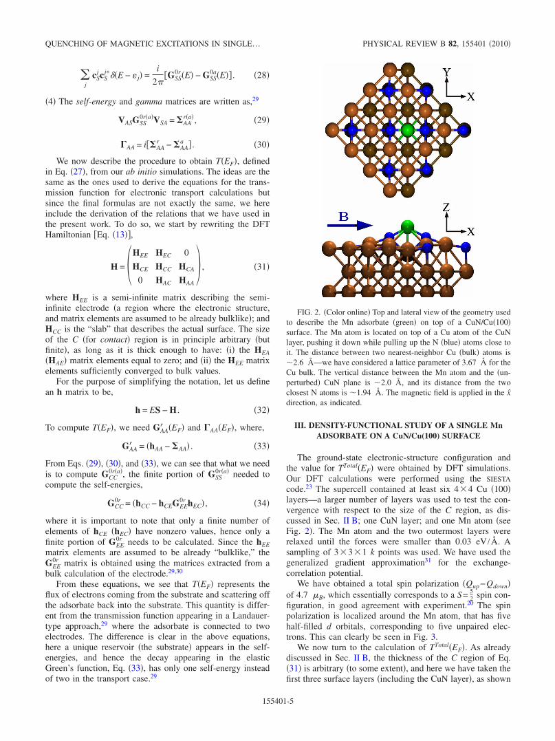
The corresponding population of excited states for a junc-tion conductance at V=0 equal to 210−6 S, a magnetic Bfield of 3 T and a tip polarization equal to �=0.24 are shownin Fig. 11 as a function of V. Below the threshold for the0→1 transition, the population is entirely in the groundstate, beyond this threshold the excited state populationquickly increases as �V� increases. One can notice that theexcitation process at 3 T basically goes step by step fromstate 0 to 5 following the energy �and index� order, so thatexcitation of the higher-lying states is a multiple order pro-cess and rises much more slowly than excitation to state 1.At large �V�, the system reaches a regime where the popula-tion is independent of V, it corresponds to the situation wheretransitions �excitation and deexcitation� induced by tunnelingelectrons dominate over the excited state decay. Excitationby electrons and holes are very different leading to very dif-ferent excited-state populations in the V�0 and V�0 cases.Down polarized holes have a much higher excitation effi-ciency than down polarized electrons, and this is a directconsequence of the effects observed in Figs. 7 and 8 and
-30 -20 -10 0 10 20 30Voltage (mV)
0
0.2
0.4
0.6
0.8
1
Pop
ulat
ion
n=0n=1n=2n=3n=4n=5
B= 3 T
η= 0.24
FIG. 11. �Color online� Population of the six magnetic states inthe Mn/CuN/Cu�100� system as a function of the tip bias. The mag-netic field is along the x axis and equal to 3 T. The tip polarization,�, is equal to 0.24. The conductance at zero bias is equal to210−6 S.
NOVAES, LORENTE, AND GAUYACQ PHYSICAL REVIEW B 82, 155401 �2010�
155401-10

discussed above. Actually, if we forget the very tiny excita-tions that correspond to the nonperfect Zeeman limit, a fullypolarized tip would only lead to an excited-state populationfor V�0 �see Fig. 7�; here with a finite � polarization, theexcited-state populations at V�0 are due to the minority-spin direction electrons in the tip. Indeed for a nonpolarizedtip, excitation by electrons and holes are equivalent, consis-tently with Fig. 9.
D. Modeling of Loth et al. experiment
Figures 12 and 13 present the conductivity of the Mnjunction computed with a finite excited-state population fordifferent values of the conductance at V=0:0.1,0.2,0.5,1. ,2. ,5, and 10. �all in 10−6 S�. They corre-spond to a B field of 3 and 7 T, respectively, and a tip polar-ization of 0.24. The computed conductivity as a function of
V has been convoluted with a Gaussian of 0.2 meV width tomimic the various broadening phenomena. Note that the ac-tual height of the inelastic conductivity step for B=3 T de-pends on the magnitude of the broadening effect, due to thesmall excitation energies �Fig. 1�. The behavior is the sameas observed experimentally: �i� there is a sharp peak at verylow voltage corresponding to the excitation thresholds; �ii�the conductivity drops as �V� is increased due to the excitedstate population; �iii� this drop is steeper and deeper on theV�0 side; �iv� the steepness of the conductivity drop de-creases as the tunneling current decreases to practically van-ish for very small conductances and �v� the conductance dropis steeper at 3 T than at 7 T due to a longer lifetime of theexcited states at 3 T. The height of the inelastic steps andtheir asymmetry around zero, as well as the extent of thedecrease in the conductance as �V� increases depends on thepolarization of the tip. In the case of an unpolarized tip��=0�, Fig. 14 shows that, in the same way as for the ex-perimental results, the conductivity is symmetric for V�0and V�0 and it is practically independent of the tunnelingcurrent, although a significant population of excited states ispresent. Figure 15 shows the excited state population as afunction of the junction bias for a conductivity of2.010−6 S at V=0 and for an unpolarized tip. For largebias, the excited-state populations are large �their sum islarger than the population of the ground state�; they are equalfor positive and negative biases. Though no effect of theseexcited-state populations is apparent in Fig. 14. This is adirect consequence of Fig. 9 where the conductances of allthe magnetic states are equal above the excitation thresholdsin the case of unpolarized electrons �or holes�. Differencescould only appear in the voltage region in between the in-elastic thresholds, but in the present case, due to the small-ness of the difference between the various excitation energythresholds, they are hidden by broadening effects. All thesequalitative features nicely agree with the experimental obser-vations. The two sets though differ quantitatively, coherentlywith the decay rate comparison in Fig. 6. The computed
-20 0 20Voltage (mV)
0.8
0.9
1
1.1R
elat
ive
Con
duct
ance
0.1 x 10⁻⁶
S
0.2 x 10⁻⁶
S
0.5 x 10⁻⁶
S
1 x 10⁻⁶
S
2 x 10⁻⁶
S
5 x 10⁻⁶
S
10 x 10-6
S
B= 3Tη= 0.24
FIG. 12. �Color online� Relative conductance of the Mn/CuN/Cu�100� system as a function the tip bias. The tip polarization is�=0.24 and the B field, equal to 3 T, is along the x axis. The finitepopulation of the excited states is taken into account. The variouscurves correspond to various absolute conductances at zero bias�0.1, 0.2, 0.5, 1., 2., 5, and 1010−6 S�. In the figure, the conduc-tance is plotted in relative value, with the conductance for zero biasset to 1.
-20 0 20Voltage (mV)
0.8
0.9
1
1.1
1.2
Rel
ativ
eC
ondu
ctan
ce
0.1 x 10⁻⁶
S
0.2 x 10⁻⁶
S
0.5 x 10⁻⁶
S
1 x 10⁻⁶
S
2 x 10⁻⁶
S
5 x 10⁻⁶
S
10 x 10-6
S
B= 7Tη= 0.24
FIG. 13. �Color online� Relative conductance of the Mn/CuN/Cu�100� system as a function the tip bias. The tip polarization is�=0.24 and the B field, equal to 7 T, is along the x axis. The finitepopulation of the excited states is taken into account. The variouscurves correspond to various absolute conductances at zero bias�0.1, 0.2, 0.5, 1., 2., 5, and 1010−6 S�. In the figure, the conduc-tance is plotted in relative value, with the conductance for zero biasset to 1.
-2 -1 0 1 2Voltage (mV)
0.9
1
1.1
1.2
1.3
Rel
ativ
eC
ondu
ctan
ce
2 x 10⁻⁶
S
B= 3Tη= 0.0
FIG. 14. �Color online� Relative conductance of the Mn/CuN/Cu�100� system as a function the tip bias. The tip is nonpolarizedand the B field, equal to 3 T, is along the x axis. The finite popula-tion of the excited states is taken into account. The conductance isindependent of the current. In the figure, the conductance is plottedin relative value, with the conductance for zero bias set to 1.
QUENCHING OF MAGNETIC EXCITATIONS IN SINGLE… PHYSICAL REVIEW B 82, 155401 �2010�
155401-11
lifetimes are shorter and consequently, the effect of theexcited-state population on the junction conductivity appearsfor larger conductances and larger tunneling currents.
The effect of the populations of excited states on the po-larized conductance is much visible in Figs. 12 and 13 whichshow the conductance as a function of bias for a fixed tipposition. They also strongly emphasize a dependence of theconductance on the conductivity at V=0. One can stress thatif all the curves in, e.g., Fig. 12 are plotted as a function ofthe junction current intensity, then they look very muchalike, the population of the excited states depending domi-nantly on the current intensity. In such a plot, the role of thebias voltage and conductivity at V=0 only appear in the ex-citation threshold region.
E. Symmetry of the tunneling process
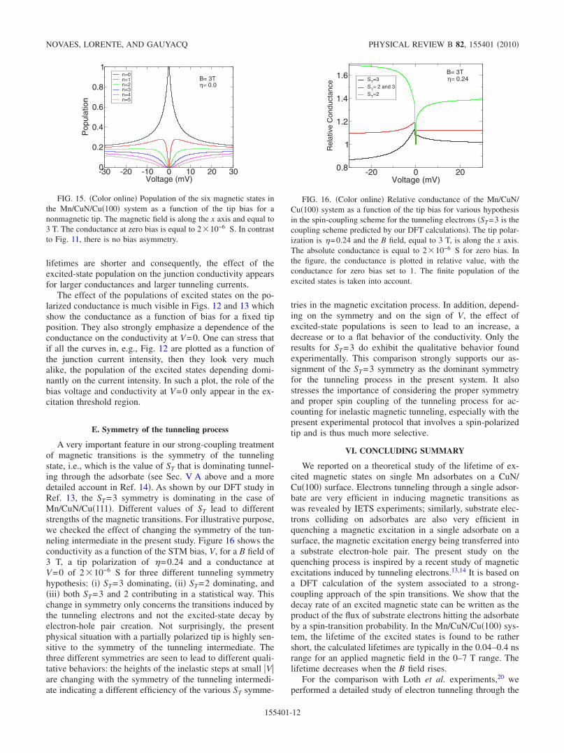
A very important feature in our strong-coupling treatmentof magnetic transitions is the symmetry of the tunnelingstate, i.e., which is the value of ST that is dominating tunnel-ing through the adsorbate �see Sec. V A above and a moredetailed account in Ref. 14�. As shown by our DFT study inRef. 13, the ST=3 symmetry is dominating in the case ofMn/CuN/Cu�111�. Different values of ST lead to differentstrengths of the magnetic transitions. For illustrative purpose,we checked the effect of changing the symmetry of the tun-neling intermediate in the present study. Figure 16 shows theconductivity as a function of the STM bias, V, for a B field of3 T, a tip polarization of �=0.24 and a conductance atV=0 of 210−6 S for three different tunneling symmetryhypothesis: �i� ST=3 dominating, �ii� ST=2 dominating, and�iii� both ST=3 and 2 contributing in a statistical way. Thischange in symmetry only concerns the transitions induced bythe tunneling electrons and not the excited-state decay byelectron-hole pair creation. Not surprisingly, the presentphysical situation with a partially polarized tip is highly sen-sitive to the symmetry of the tunneling intermediate. Thethree different symmetries are seen to lead to different quali-tative behaviors: the heights of the inelastic steps at small �V�are changing with the symmetry of the tunneling intermedi-ate indicating a different efficiency of the various ST symme-
tries in the magnetic excitation process. In addition, depend-ing on the symmetry and on the sign of V, the effect ofexcited-state populations is seen to lead to an increase, adecrease or to a flat behavior of the conductivity. Only theresults for ST=3 do exhibit the qualitative behavior foundexperimentally. This comparison strongly supports our as-signment of the ST=3 symmetry as the dominant symmetryfor the tunneling process in the present system. It alsostresses the importance of considering the proper symmetryand proper spin coupling of the tunneling process for ac-counting for inelastic magnetic tunneling, especially with thepresent experimental protocol that involves a spin-polarizedtip and is thus much more selective.
VI. CONCLUDING SUMMARY
We reported on a theoretical study of the lifetime of ex-cited magnetic states on single Mn adsorbates on a CuN/Cu�100� surface. Electrons tunneling through a single adsor-bate are very efficient in inducing magnetic transitions aswas revealed by IETS experiments; similarly, substrate elec-trons colliding on adsorbates are also very efficient inquenching a magnetic excitation in a single adsorbate on asurface, the magnetic excitation energy being transferred intoa substrate electron-hole pair. The present study on thequenching process is inspired by a recent study of magneticexcitations induced by tunneling electrons.13,14 It is based ona DFT calculation of the system associated to a strong-coupling approach of the spin transitions. We show that thedecay rate of an excited magnetic state can be written as theproduct of the flux of substrate electrons hitting the adsorbateby a spin-transition probability. In the Mn/CuN/Cu�100� sys-tem, the lifetime of the excited states is found to be rathershort, the calculated lifetimes are typically in the 0.04–0.4 nsrange for an applied magnetic field in the 0–7 T range. Thelifetime decreases when the B field rises.
For the comparison with Loth et al. experiments,20 weperformed a detailed study of electron tunneling through the
-30 -20 -10 0 10 20 30Voltage (mV)
0
0.2
0.4
0.6
0.8
1
Pop
ulat
ion
n=0n=1n=2n=3n=4n=5
B= 3Tη= 0.0
FIG. 15. �Color online� Population of the six magnetic states inthe Mn/CuN/Cu�100� system as a function of the tip bias for anonmagnetic tip. The magnetic field is along the x axis and equal to3 T. The conductance at zero bias is equal to 210−6 S. In contrastto Fig. 11, there is no bias asymmetry.
-20 0 20Voltage (mV)
0.8
1
1.2
1.4
1.6
Rel
ativ
eC
ondu
ctan
ce
ST=3ST= 2 and 3ST=2
B= 3Tη= 0.24
FIG. 16. �Color online� Relative conductance of the Mn/CuN/Cu�100� system as a function of the tip bias for various hypothesisin the spin-coupling scheme for the tunneling electrons �ST=3 is thecoupling scheme predicted by our DFT calculations�. The tip polar-ization is �=0.24 and the B field, equal to 3 T, is along the x axis.The absolute conductance is equal to 210−6 S for zero bias. Inthe figure, the conductance is plotted in relative value, with theconductance for zero bias set to 1. The finite population of theexcited states is taken into account.
NOVAES, LORENTE, AND GAUYACQ PHYSICAL REVIEW B 82, 155401 �2010�
155401-12

adsorbed Mn atom in the case of a polarized tip. Using po-larized electrons �or holes� unveils several phenomenaamong which we can stress: �1� as shown in our strong-coupling approach, the selection introduced by the symmetryof the total spin state in the tunneling process �total spin=spin of the tunneling electron+spin of the adsorbate� isvery important and this leads to large differences in conduc-tance between various situations: tunneling electrons or holeswith spin up �or down�, adsorbates in different magneticstates. All these can be related to the existence of a dominantspin symmetry in the tunneling process, which is ST=3 in thecase of Mn on CuN/Cu�100� as shown here.
�2� As the excitation probability by tunneling electrons islarge, significant populations of excited states can exist for afinite current. Very interestingly, this leads to observablechanges in the conductance as a function of current in thecase of a polarized tip but not in the case of a nonpolarizedtip. This is a direct consequence of one of the key propertiesof the magnetic excitation process, as described in thestrong-coupling approach. The excitation process appears asa sharing process: a global tunneling current is shared amongthe various magnetic states, using sharing probabilities ob-tained from spin-coupling coefficients. If we sum over allpossible spin directions for the tunneling electron, these spin-coupling coefficients sum to one. Thus, with a nonpolarized
tip, the conductance for biases above all inelastic thresholdsis independent of the initial state and then independent of afinite stationary population of excited states. In contrast, inthe case of a polarized tip, the sum over electron spin direc-tions is not complete and the conductance depends signifi-cantly on the magnetic state.
�3� The present theoretical results reproduce all the behav-iors observed experimentally, basically those are conse-quences of the two phenomena described above. Quantita-tively, although the excitation process is perfectly accountedfor, the computed lifetimes of the excited states appear to bea factor of 3 shorter than those extracted from experiment.As a consequence, the experimentally observed variation inthe junction conductivity with the tunneling current is repro-duced but for larger tunneling currents. Recently we becameaware of a complementary work by Delgado andFernández-Roissier.36
ACKNOWLEDGMENTS
F.D.N acknowledges support from Spain’s MICINN Juande la Cierva program. Computing resources from CESGAare gratefully acknowledged. Financial support from thespanish MICINN through Grant No. FIS2009-12721-C04-01is gratefully acknowledged.
1 C. F. Hirjibehedin, C. P. Lutz, and A. J. Heinrich, Science 312,1021 �2006�.
2 C. F. Hirjibehedin, C.-Y. Lin, A. F. Otte, M. Ternes, C. P. Lutz,B. A. Jones, and A. J. Heinrich, Science 317, 1199 �2007�.
3 N. Tsukahara, K. I. Noto, M. Ohara, S. Shiraki, N. Takagi, Y.Takata, J. Miyawaki, M. Taguchi, A. Chainani, S. Shin, and M.Kawai, Phys. Rev. Lett. 102, 167203 �2009�.
4 Xi Chen, Y.-S. Fu, S.-H. Ji, T. Zhang, P. Cheng, X.-C. Ma, X.-L.Zou, W.-H. Duan, J.-F. Jia, and Q.-K. Xue, Phys. Rev. Lett. 101,197208 �2008�.
5 C. Iacovita, M. V. Rastei, B. W. Heinrich, T. Brumme, J. Kortus,L. Limot, and J. P. Bucher, Phys. Rev. Lett. 101, 116602�2008�.
6 Y.-S. Fu, T. Zhang, S.-H. Ji, X. Chen, X.-C. Ma, J.-F. Jia, andQ.-K. Xue, Phys. Rev. Lett. 103, 257202 �2009�.
7 W. Ho, J. Chem. Phys. 117, 11033 �2002�.8 T. Komeda, Prog. Surf. Sci. 78, 41 �2005�.9 N. Lorente and M. Persson, Phys. Rev. Lett. 85, 2997 �2000�.
10 J. Fransson, Nano Lett. 9, 2414 �2009�.11 J. Fernández-Rossier, Phys. Rev. Lett. 102, 256802 �2009�.12 M. Persson, Phys. Rev. Lett. 103, 050801 �2009�.13 N. Lorente and J.-P. Gauyacq, Phys. Rev. Lett. 103, 176601
�2009�.14 J.-P. Gauyacq, F. D. Novaes, and N. Lorente, Phys. Rev. B 81,
165423 �2010�.15 F. Delgado, J. J. Palacios, and J. Fernández-Rossier, Phys. Rev.
Lett. 104, 026601 �2010�.16 B. Sothmann and J. König, New J. Phys. 12, 083028 �2010�.17 R. Žitko and Th. Pruschke, New J. Phys. 12, 063040 �2010�.18 T. Balashov, T. Schuh, A. F. Takacs, A. Ernst, S. Ostanin, J.
Henk, I. Mertig, P. Bruno, T. Miyamachi, S. Suga, and W. Wulf-hekel, Phys. Rev. Lett. 102, 257203 �2009�.
19 J. Fabian and S. Das Sarma, J. Vac. Sci. Technol. B 17, 1708�1999�.
20 S. Loth, K. von Bergmann, M. Ternes, A. F. Otte, C. P. Lutz, andA. J. Heinrich, Nat. Phys. 6, 340 �2010�.
21 K.Yosida Theory of Magnetism, Springer Series in Solid-StateScience �Springer, Berlin, 1996�.
22 N. Lorente, in Dynamics, Handbook of Surface Science, editedby E. Hasselbrink and B. I. Lundqvist �North-Holland, Amster-dam, 2008�, p. 613.
23 J. M. Soler, E. Artacho, J. D. Gale, A. Garcia, J. Junquera, P.Ordejon, and D. Sanchez-Portal, J. Phys.: Condens. Matter 14,2745 �2002�.
24 F. D. Novaes, A. J. R. da Silva, and A. Fazzio, Brazilian J Phys.36, 799 �2006�.
25 G. Autès, C. Barreteau, D. Spanjaard, and M. C. Desjonquères,Phys. Rev. B 77, 155437 �2008�.
26 A. R. Williams, P. J. Feibelman, and N. D. Lang, Phys. Rev. B26, 5433 �1982�.
27 E. Emberly and G. Kirczenow, Phys. Rev. Lett. 81, 5205�1998�.
28 E. N. Economou, Green’s Functions in Quantum Physics�Springer-Verlag, Berlin, 1990�.
29 M. Brandbyge, J. L. Mozos, P. Ordejon, J. Taylor, and K. Stok-bro, Phys. Rev. B 65, 165401 �2002�.
30 M. P. López Sancho, J. M. López Sancho, and J. Rubio, J. Phys.F: Met. Phys. 14, 1205 �1984�.
31 J. P. Perdew, K. Burke, and M. Ernzerhof, Phys. Rev. Lett. 77,3865 �1996�.
QUENCHING OF MAGNETIC EXCITATIONS IN SINGLE… PHYSICAL REVIEW B 82, 155401 �2010�
155401-13

32 R. A. Abram and A. Herzenberg, Chem. Phys. Lett. 3, 187�1969�.
33 D. Teillet-Billy, L. Malegat, and J. P. Gauyacq, J. Phys. B 20,3201 �1987�.
34 B. Bahrim, D. Teillet-Billy, and J. P. Gauyacq, Phys. Rev. B 50,
7860 �1994�.35 D. Teillet-Billy, J. P. Gauyacq, and M. Persson, Phys. Rev. B 62,
R13306 �2000�.36 F. Delgado and J. Fernández Rossier, e-print arXiv:1006.5608v1
�unpublished�.
NOVAES, LORENTE, AND GAUYACQ PHYSICAL REVIEW B 82, 155401 �2010�
155401-14