Embed Size (px)
Citation preview

FEATURE
Quenching and Partitioning Steel Heat Treatment
Li Wang • John G. Speer
� ASM International 2013
Quenching and partitioning (Q&P) steel is a term used to
describe a series of C–Si–Mn, C–Si–Mn–Al, or other steels
subjected to the recently developed Q&P heat treatment
process. The purpose of Q&P steel in the context of
automotive structures is to obtain a new type of ultrahigh-
strength steel with good ductility to improve fuel economy
while promoting passenger safety. With a final micro-
structure of ferrite (in the case of partial austenitization),
martensite, and retained austenite, Q&P steel exhibits an
excellent combination of strength and ductility, which
permits its use in a new generation of advanced high-
strength steels (AHSS) for automobiles. While autobody
application represents the first implementation of Q&P on
an industrial scale, the heat treatment concept is also
applicable to a range of other potential applications.
In 2003, Speer et al. [1] first proposed an approach
designated as the Q&P process to exploit novel martensitic
steels containing retained austenite (Q&P steel), based on
the fact that carbon can diffuse from supersaturated mar-
tensite into neighboring untransformed austenite and sta-
bilize it to room temperature. The Q&P steel is first treated
by an initial partial or full austenitization and then followed
by an interrupted quench to a temperature between the
martensite start (Ms) and martensite finish (Mf)
temperatures, resulting in untransformed retained austenite,
and an anneal or so-called partitioning treatment either at
or above the initial quench temperature. With enhanced
silicon alloying suppressing cementite precipitation, it is
anticipated that retained austenite will be enriched with
carbon expected to escape from the supersaturated mar-
tensite phase in which it has very low solid solubility. The
treatment should then produce a fine acicular aggregate of
carbon-depleted and potentially carbide-free martensite
laths interwoven with retained austenite stabilized by car-
bon enrichment. As a result, with a composition of 0.2% C,
1–1.5% Al, and 1–1.5% Mn, Q&P steel [2] shows an
ultrahigh strength of 1000–1400 MPa (145–200 ksi) with
adequate ductility of 10–20%; property advancements
continue to be made through research on this emerging
technology. Early investigations [1] also proposed a cor-
responding thermodynamic model for Q&P steel and its
heat treatment, which is now referred to as constrained
carbon equilibrium [3].
Since first proposed in 2003, Q&P steel has gained
interest for its potential to enhance properties of strength
and ductility with compositions similar to transformation-
induced plasticity (TRIP) steel and has been proposed as a
third-generation automotive steel (Fig. 1) [4]. Many
researchers [5–17] have investigated the relationship
between properties and microstructures of Q&P steels
subjected to various heat treatments and showed that the
ultrahigh strength of Q&P steel results from martensite
laths, while its good ductility is attributed to TRIP-assisted
behavior of retained austenite during deformation. De
Moor et al. [14] examined the stability of retained austenite
and showed that the TRIP effect occurs in Q&P steels,
thereby effectively contributing to the significant strain
hardening. Santofimia et al. [15, 16] and Takahama et al.
[17] analyzed microstructural evolution during annealing
Editor’s Note The following is a preview chapter from theupcoming volume Steel Heat Treating Fundamentals and Processes,Volume 4A, ASM Handbook, Jon Dossett and George Totten, editors.The volume is scheduled for publication later this year.
L. Wang
Automotive Steel Research Institute and Baoshan Iron & Steel
Company, Ltd, Shanghai, China
J. G. Speer
Colorado School of Mines, Golden, CO, USA
123
Metallogr. Microstruct. Anal. (2013) 2:268–281
DOI 10.1007/s13632-013-0082-8

by using a model considering the influence of martensite–
austenite interface migration on the kinetics of carbon
partitioning and indicated that different interface mobilities
lead to profound differences in the evolution of micro-
structures during the partitioning process. In addition,
processing opportunities for Q&P steels were discussed by
Matlock and Speer [18] and Thomas et al. [19, 20] based
on the considerations in the application of the Q&P concept
to automotive AHSS production. Additional work has been
subsequently published by multiple research groups. In
2009, the world’s first industrially processed Q&P cold
rolled sheet steel was produced by Baosteel, having a
tensile strength over 980 MPa (142 ksi) and ductility over
15%. In 2012, Q&P steel with a tensile strength of
980 MPa was successfully commercialized [21–23], and a
1180 MPa (170 ksi) tensile strength Q&P sheet grade is
under development. This article provides an overview of
important background and product characteristics, with a
focus on the automotive sheet steel application that has
now reached commercialization. The Q&P heat treating
concept has broader potential and may be extended to other
products and applications in the future.
Chemical Composition and Annealing Process
The chemical compositions of typical Q&P steels are listed
in Table 1. The Q&P steels are hypoeutectoid iron–carbon
alloys that typically contain 0.15–0.30% C by weight,
similar to TRIP steels. The Q&P steels also contain
alloying elements such as silicon that prevent the
precipitation of the cementite phase (Fe3C), which is
present in typical steels at room temperature. This main-
tains the high carbon concentration in the austenite phase,
which becomes stable at room temperature. Carbon content
in current Q&P steels is limited to 0.15–0.30 wt% due to
weldability concerns. As shown in Table 1, the manganese
content in Q&P steels is relatively high, to enhance
hardenability and austenite stability. Silicon is used to
stabilize the austenite phase during continuous annealing
and at room temperature, because silicon significantly
increases the carbon activity in both ferrite and austenite
and decreases carbon solubility in ferrite. As a result, sil-
icon inhibits the formation of cementite during the parti-
tioning stage. Because Q&P steels have already exhibited
an excellent balance between ultrahigh strength and high
ductility, other alloying elements have not been necessary,
although opportunity is likely available to use microal-
loying and other concepts for additional enhancements.
Thermal Profile and Phase Transformation
The continuous annealing process and consequent phase-
transformation behaviors of Q&P steels are schematically
shown in Fig. 2. To produce Q&P steel with ultrahigh
strength and excellent ductility, a unique annealing process
is conducted to obtain the appropriate phase distribution.
First, the steel is heated to a temperature above Ac3
(annealing temperature), where the material is composed of
austenite. The material is then slowly cooled to a temper-
ature below Ar3 (slow cooling temperature, or SC), which
is approximately 740 �C (1360 �F) for the 980 MPa
(142 ksi) steel grade, to allow the formation of a certain
amount of proeutectoid ferrite. The ferrite phase plays a
significant role in the improvement of ductility of the
980 MPa material. The fraction of ferrite and martensite
phases can be adjusted by precisely controlling SC. After
slow cooling, the steel is then quenched to a temperature
between Ms and Mf (quenching temperature) with a cooling
rate higher than 50 �C/s (90 �F/s), wherein austenite
Fig. 1 Predicted potential for austenite/martensite mixtures to
achieve property targets beyond those of ferrite/martensite mixtures
for third-generation advanced high-strength sheet steels. Source [4]
Table 1 Chemical compositions of current-generation Q&P steels
Chemical composition, wt%
C Mn Si Al P S
0.15–0.30 1.5–3.0 1.0–2.0 0.02–0.06 \0.015 \0.01
Fig. 2 Schematic illustration of the thermal profile and phase-
transformation behavior of Q&P steels. QT quenching temperature,
PT partitioning temperature
Metallogr. Microstruct. Anal. (2013) 2:268–281 269
123

transforms (partially) to martensite. The fractions of aus-
tenite and martensite can be controlled by this interrupted
quenching process. After quenching, the steel is usually
reheated to a higher temperature (partitioning temperature)
and held for a couple of minutes. In a typical steel alloy,
the supersaturated carbon in martensite would lead to
cementite precipitation. However, the high content of sil-
icon prevents the formation of cementite. Consequently,
the excess carbon in the martensite phase partitions into the
remaining austenite, because austenite with a face-centered
cubic structure exhibits much higher carbon solubility than
martensite with a body-centered cubic structure. Finally,
the stable carbon-enriched austenite is retained when the
steel is cooled to room temperature. After this unique heat
treatment, the final microstructure composed of ferrite,
martensite, and retained austenite is achieved. The key
annealing considerations to produce Q&P steels are that
fast cooling is needed, and, at the same time, the quench
arrest temperature must be easily controlled below the Ms
temperature.
Microstructure and Mechanical Properties
The microstructure of commercial Q&P steels is composed
primarily of martensite (50–80%) formed during quench-
ing, and ferrite (20–40%) formed from the austenite phase
during slow cooling, as well as dispersed retained austenite
(5–10%) stabilized by carbon enrichment during parti-
tioning. Reduced fractions of ferrite can be used in higher-
strength products. Example micrographs taken with a
scanning electron microscope and a light optical micro-
scope can be seen in Fig. 3. Small nodules of retained
austenite are found, and films of austenite are also present
in the lath martensite. The fine Q&P microstructure is
usually not well resolved by light optical microscopy.
Some additional aspects related to microstructure are also
included in the following sections.
Mechanical Properties
Carbon-enriched metastable retained austenite is considered
beneficial because TRIP during deformation, that is, the TRIP
phenomenon, can contribute to work hardening, formability,
and fracture toughness. During deformation, the dispersed
retained austenite progressively transforms to harder mar-
tensite, which creates a high work-hardening rate, even at
higher strain levels. A typical strain–stress curve is shown in
Fig. 4. It can be seen that with a tensile strength of 980 MPa
(142 ksi), the total elongation of Q&P steel is approximately
20%. Mechanical properties of industrially produced Q&P
steels are listed in Table 2 for minimum tensile strength levels
of 980 and 1180 MPa (142 and 170 ksi).
Applications
The Q&P steels with ultrahigh strength and excellent
ductility, or formability, are well suited to help reduce
weight of car bodies, with the added advantage of
enhanced occupant safety. The work-hardening rates of
Q&P steels are substantially higher than for conventional
high-strength steels (HSS), providing significant stretch-
forming capability. Compared to most other HSS with the
same tensile strength, Q&P steels exhibit much higher
formability; hence, they are particularly well suited for
automotive structural and safety parts such as cross mem-
bers, longitudinal beams, B-pillar reinforcements, sills, and
bumper reinforcements, which cannot be cold formed using
conventional HSS with similar strength levels. Some typ-
ical automotive parts produced from Q&P steels are shown
in Fig. 5. This family of steels is at an early stage of
industrial implementation and may find its way into other
Fig. 3 Microstructure of Q&P steel obtained using (a) scanning electron microscopy and (b) light optical microscopy. M martensite, F ferrite,
RA retained austenite
270 Metallogr. Microstruct. Anal. (2013) 2:268–281
123

high-strength components for both automotive and other
applications.
Forming
The Q&P steels offer high ductility for their tensile
strength. For example, cold rolled Q&P 980 has a total
elongation of approximately 20%, and cold rolled Q&P
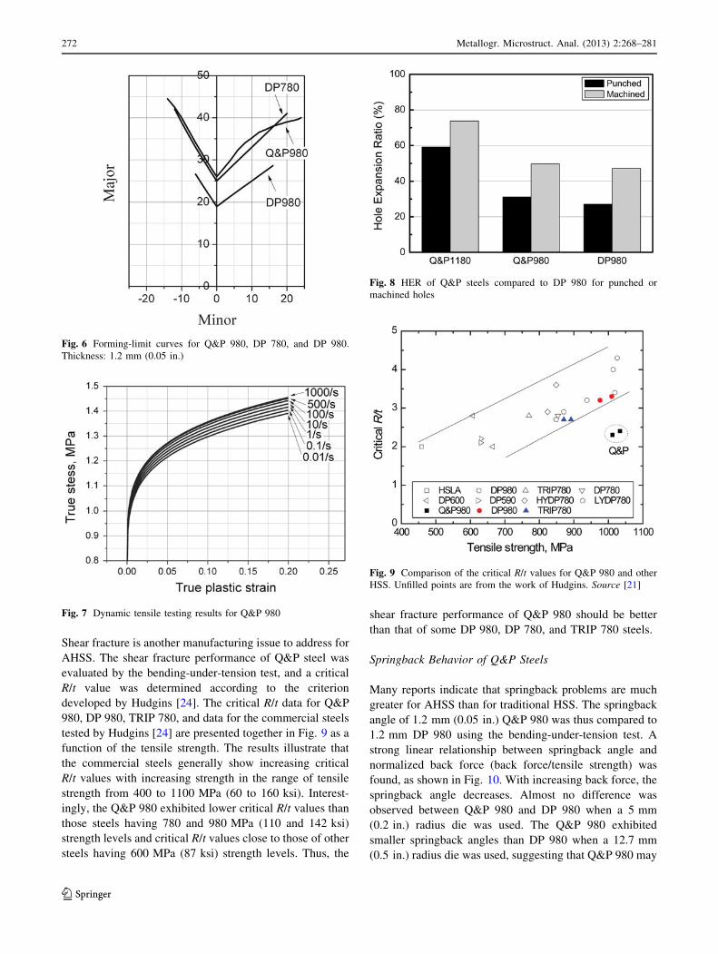
1180 has a total elongation of approximately 12%. Figure 6
shows typical forming-limit curves for cold rolled Q&P
980, dual-phase (DP) 780, and DP 980 steels. The form-
ability of Q&P 980 is superior to that of DP 980 steel and
reaches to the level of DP 780.
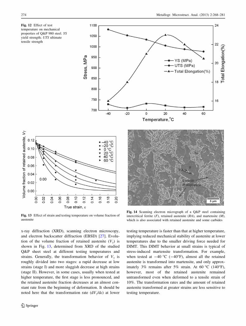
Dynamic Tensile Properties
Besides quasi-static tensile testing results, dynamic tensile
testing of sheet steels is also important for more precise
evaluation of vehicle crashworthiness in the automotive
industry. Positive strain-rate sensitivity, that is, strength
increases with strain rate, offers a potential for improved
energy absorption during a crash event. The results of
dynamic tensile testing of Q&P 980 are shown in Fig. 7.
The results confirm that Q&P steel exhibits positive strain-
rate sensitivity.
Application Properties of Q&P Steels
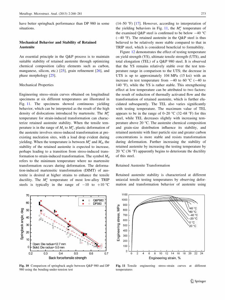
Hole-Expansion Ratio (HER) of Q&P Steels
One of the concerns for AHSS in stamping operations is
the failure of sheared edges in stretching modes. The HER
is usually used to characterize the sheared-edge stretch-
ability. The HER of Q&P 1180 and Q&P 980 compared to
DP 980 is shown in Fig. 8. For either punched or machined
edges, Q&P 1180 shows higher HER than Q&P 980 and
DP 980, while Q&P 980 shows similar HER as DP 980.
One possible explanation of the high HER of Q&P 1180 is
its high yield strength/tensile strength ratio and uniform
microstructure. It should be noted that the HER can be
significantly lower for punched holes compared with
machined holes. This probably is due to the reduced local
elongation of the multiphase steels, which can have inter-
facial failure between the ductile ferrite matrix and the
harder phases.
Shear Fracture Behavior of Q&P Steels
Shear fracture can happen during stretching over the die
radii for some part geometries at strains below the con-
ventional forming limit of the material; thus, computer
simulations often fail to predict this type of fracture using
the conventional forming limit as the failure criterion.
Fig. 4 Strain–stress curve of industrially produced 980 MPa
(142 ksi)-grade Q&P steel
Fig. 5 (a) B-pillar reinforcement left/right. Material: 980 Q&P steel;
gage: 2.0 mm (0.08 in.). (b) B-pillar inner. Material: 980 Q&P; gage:
1.2 mm (0.05 in.). (c) Side member front floor left. Material: 980
Q&P; gage: 1.8 mm (0.07 in.). (d) Door panel inner left/right.
Material: 980 Q&P; gage: 1.0 mm (0.04 in.)
Table 2 Typical mechanical property ranges for current-generation
Q&P steels
Steel Yield strength Tensile strength Elongation,
%MPa ksi MPa ksi
Q&P
980
650–800 95–115 980–1050 140–150 17–22
Q&P
1180
950–1150 140–170 1180–1300 170–190 8–14
Metallogr. Microstruct. Anal. (2013) 2:268–281 271
123
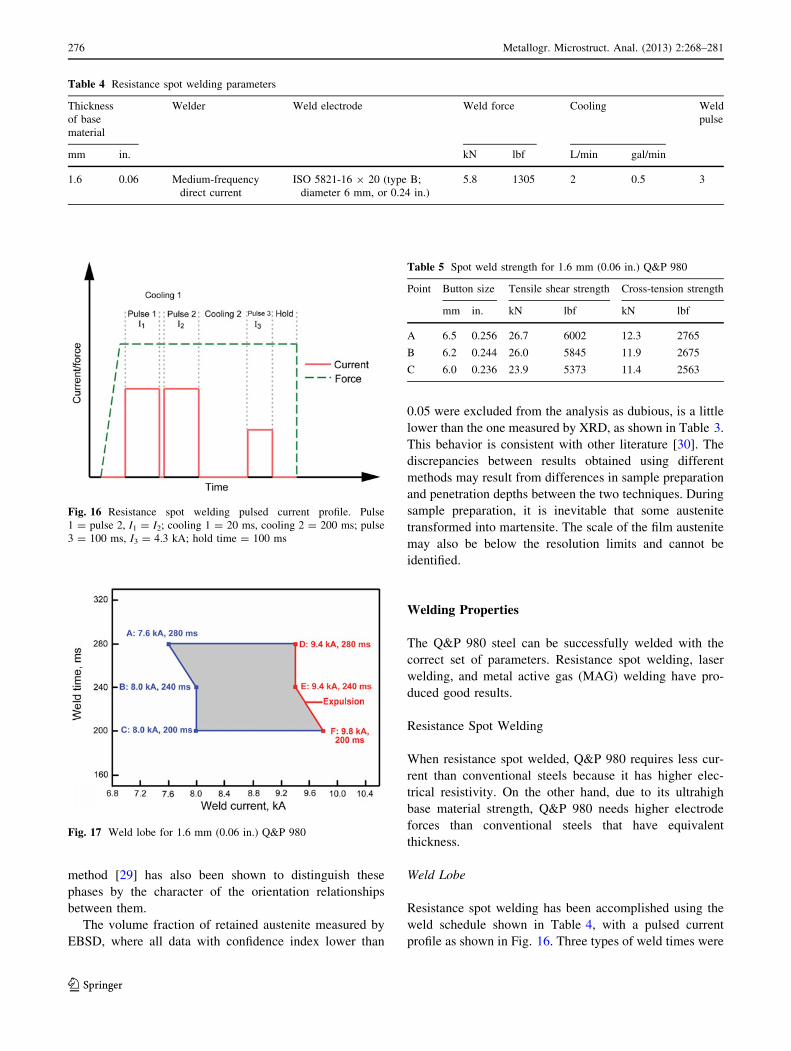
Shear fracture is another manufacturing issue to address for
AHSS. The shear fracture performance of Q&P steel was
evaluated by the bending-under-tension test, and a critical
R/t value was determined according to the criterion
developed by Hudgins [24]. The critical R/t data for Q&P
980, DP 980, TRIP 780, and data for the commercial steels
tested by Hudgins [24] are presented together in Fig. 9 as a
function of the tensile strength. The results illustrate that
the commercial steels generally show increasing critical
R/t values with increasing strength in the range of tensile
strength from 400 to 1100 MPa (60 to 160 ksi). Interest-
ingly, the Q&P 980 exhibited lower critical R/t values than
those steels having 780 and 980 MPa (110 and 142 ksi)
strength levels and critical R/t values close to those of other
steels having 600 MPa (87 ksi) strength levels. Thus, the
shear fracture performance of Q&P 980 should be better
than that of some DP 980, DP 780, and TRIP 780 steels.
Springback Behavior of Q&P Steels
Many reports indicate that springback problems are much
greater for AHSS than for traditional HSS. The springback
angle of 1.2 mm (0.05 in.) Q&P 980 was thus compared to
1.2 mm DP 980 using the bending-under-tension test. A
strong linear relationship between springback angle and
normalized back force (back force/tensile strength) was
found, as shown in Fig. 10. With increasing back force, the
springback angle decreases. Almost no difference was
observed between Q&P 980 and DP 980 when a 5 mm
(0.2 in.) radius die was used. The Q&P 980 exhibited
smaller springback angles than DP 980 when a 12.7 mm
(0.5 in.) radius die was used, suggesting that Q&P 980 may
Fig. 6 Forming-limit curves for Q&P 980, DP 780, and DP 980.
Thickness: 1.2 mm (0.05 in.)
Fig. 7 Dynamic tensile testing results for Q&P 980
Fig. 8 HER of Q&P steels compared to DP 980 for punched or
machined holes
Fig. 9 Comparison of the critical R/t values for Q&P 980 and other
HSS. Unfilled points are from the work of Hudgins. Source [21]
272 Metallogr. Microstruct. Anal. (2013) 2:268–281
123
have better springback performance than DP 980 in some
situations.
Mechanical Behavior and Stability of Retained
Austenite
An essential principle in the Q&P process is to maintain
suitable stability of retained austenite through optimizing
chemical composition (alloy elements such as carbon,
manganese, silicon, etc.) [25], grain refinement [26], and
phase morphology [25].
Mechanical Properties
Engineering stress–strain curves obtained on longitudinal
specimens at six different temperatures are illustrated in
Fig. 11. The specimens showed continuous yielding
behavior, which can be interpreted as the result of the high
density of dislocations introduced by martensite. The Mrs
temperature for strain-induced transformation can charac-
terize retained austenite stability. When the tensile tem-
perature is in the range of Ms to Mrs , plastic deformation of
the austenite involves stress-induced transformation at pre-
existing nucleation sites, with a load drop evident during
yielding. When the temperature is between Mrs and Md, the
stability of the retained austenite is expected to increase,
perhaps leading to a transition from stress-induced trans-
formation to strain-induced transformation. The symbol Md
refers to the minimum temperature where no martensite
transformation occurs during deformation. The deforma-
tion-induced martensitic transformation (DIMT) of aus-
tenite is desired at higher strains to enhance the tensile
ductility. The Mrs temperature of most low-alloy TRIP
steels is typically in the range of -10 to ?10 �C
(14–50 �F) [17]. However, according to interpretation of
the yielding behaviors in Fig. 11, the Mrs temperature of
the examined Q&P steel is confirmed to be below -40 �C
(-40 �F). The retained austenite in the Q&P steel is thus
believed to be relatively more stable compared to that in
TRIP steel, which is considered beneficial to formability.
Figure 12 demonstrates the effect of testing temperature
on yield strength (YS), ultimate tensile strength (UTS), and
total elongation (TEL) of a Q&P 980 steel. It is observed
that the YS remains relatively stable over the test tem-
perature range in comparison to the UTS; the decrease in
UTS is up to approximately 104 MPa (15 ksi) with an
increase in test temperature from -40 to 60 �C (-40 to
140 �F), while the YS is rather stable. This strengthening
effect at low temperature can be attributed to two factors:
the result of reduction of thermally activated flow and the
transformation of retained austenite, which is further elu-
cidated subsequently. The TEL also varies significantly
with testing temperature. The maximum value of TEL
appears to be in the range of 0–20 �C (32–68 �F) for this
steel, while TEL decreases slightly with increasing tem-
perature above 20 �C. The austenite chemical composition
and grain-size distribution influence its stability, and
retained austenite with finer particle size and greater carbon
concentrations is more stable and resists transformation
during deformation. Further increasing the stability of
retained austenite by increasing the testing temperature by
20 �C (36 �F) apparently begins to deteriorate the ductility
of this steel.
Retained Austenite Transformation
Retained austenite stability is characterized at different
uniaxial tensile testing temperatures by observing defor-
mation and transformation behavior of austenite using
Fig. 10 Comparison of springback angle between Q&P 980 and DP
980 using the bending-under-tension test
Fig. 11 Tensile engineering stress–strain curves at different
temperatures
Metallogr. Microstruct. Anal. (2013) 2:268–281 273
123
x-ray diffraction (XRD), scanning electron microscopy,
and electron backscatter diffraction (EBSD) [27]. Evolu-
tion of the volume fraction of retained austenite (Vc) is
shown in Fig. 13, determined from XRD of the studied
Q&P sheet steel at different testing temperatures and
strains. Generally, the transformation behavior of Vc is
roughly divided into two stages: a rapid decrease at low
strains (stage I) and more sluggish decrease at high strains
(stage II). However, in some cases, usually when tested at
higher temperature, the first stage is less pronounced, and
the retained austenite fraction decreases at an almost con-
stant rate from the beginning of deformation. It should be
noted here that the transformation rate (dVc/de) at lower
testing temperature is faster than that at higher temperature,
implying reduced mechanical stability of austenite at lower
temperatures due to the smaller driving force needed for
DIMT. This DIMT behavior at small strains is typical of
stress-induced martensite transformation. For example,
when tested at -40 �C (-40�F), almost all the retained
austenite is transformed into martensite, and only approx-
imately 3% remains after 5% strain. At 60 �C (140�F),
however, most of the retained austenite remained
untransformed even when deformed to a tensile strain of
10%. The transformation rates and the amount of retained
austenite transformed at greater strains are less sensitive to
testing temperature.
Fig. 12 Effect of test
temperature on mechanical
properties of Q&P 980 steel. YS
yield strength; UTS ultimate
tensile strength
Fig. 13 Effect of strain and testing temperature on volume fraction of
austenite
Fig. 14 Scanning electron micrograph of a Q&P steel containing
intercritical ferrite (F), retained austenite (RA), and martensite (M),
which is also associated with retained austenite and some carbides
274 Metallogr. Microstruct. Anal. (2013) 2:268–281
123

Microstructure Evolution with Strain
Figure 14 shows a scanning electron micrograph of a Q&P
steel after polishing and etching, showing apparently three
characteristics: a rough surface structure corresponds to
martensite, ferrite is relatively smooth with only slight
surface structure, and the retained austenite areas appear
smooth with a featureless surface structure, helping to
distinguish it from ferrite and martensite. This steel was
intercritically annealed before quenching, so a considerable
ferrite fraction is present along with the Q&P constituent
that consists of a mixture of martensite laths and retained
austenite. Ideally, formable Q&P steels should not contain
a substantial amount of iron carbide. The Q&P steel
studied here was partitioned at 400 �C (752�F) for a few
minutes, and, in this instance, the martensite regions also
contained carbides. The presence of carbides is of impor-
tance because it implies that the cementite may not have
fully dissolved, and the available carbon content does not
fully contribute to the stabilization of the carbon-enriched
austenite in the industrial processing conditions employed.
Microstructure evolution during tensile testing at dif-
ferent strain levels has been examined using EBSD. The
microstructure of specimens undergoing different strains,
that is, 0, 1, 5, and 10%, at 0 �C (32�F) was analyzed, and
Fig. 15 shows the results of a combined image-quality map
and gray-scale-coded phase map. Retained austenite is
distributed both as thin films and as larger blocky regimes.
It is clear that the retained austenite fraction decreases with
increased strain, and the remaining austenite particles are
mostly the finer ones. These results support the conclusion
that finer retained austenite is more stable with deforma-
tion. According to Santofimia et al. [28], the darker-gray
areas refer to regions that are likely martensite, based on
poor image quality due to high dislocation density, while
the lighter-gray areas perhaps represent ferrite. Another
Table 3 Retained austenite volume fraction measured by XRD and
EBSD
Method Strain, %
Initial 1 2 5 10
XRD 0.116 0.105 0.088 0.060 0.035
EBSDa 0.112 0.104 0.080 0.053 0.03
a EBSD data with confidence index values greater than 0.05
Fig. 15 EBSD maps of Q&P
steel tension tested at 0 �C
(32�F). White corresponds to
face-centered cubic lattice
(retained austenite). Gray scale
indicates the image quality,
where darker-gray scale
indicates lower image quality
(higher dislocation density).
(a) 0, (b) 1, (c) 5, and (d) 10%
strain
Metallogr. Microstruct. Anal. (2013) 2:268–281 275
123
method [29] has also been shown to distinguish these
phases by the character of the orientation relationships
between them.
The volume fraction of retained austenite measured by
EBSD, where all data with confidence index lower than
0.05 were excluded from the analysis as dubious, is a little
lower than the one measured by XRD, as shown in Table 3.
This behavior is consistent with other literature [30]. The
discrepancies between results obtained using different
methods may result from differences in sample preparation
and penetration depths between the two techniques. During
sample preparation, it is inevitable that some austenite
transformed into martensite. The scale of the film austenite
may also be below the resolution limits and cannot be
identified.
Welding Properties
The Q&P 980 steel can be successfully welded with the
correct set of parameters. Resistance spot welding, laser
welding, and metal active gas (MAG) welding have pro-
duced good results.
Resistance Spot Welding
When resistance spot welded, Q&P 980 requires less cur-
rent than conventional steels because it has higher elec-
trical resistivity. On the other hand, due to its ultrahigh
base material strength, Q&P 980 needs higher electrode
forces than conventional steels that have equivalent
thickness.
Weld Lobe
Resistance spot welding has been accomplished using the
weld schedule shown in Table 4, with a pulsed current
profile as shown in Fig. 16. Three types of weld times were
Table 4 Resistance spot welding parameters
Thickness
of base
material
Welder Weld electrode Weld force Cooling Weld
pulse
mm in. kN lbf L/min gal/min
1.6 0.06 Medium-frequency
direct current
ISO 5821-16 9 20 (type B;
diameter 6 mm, or 0.24 in.)
5.8 1305 2 0.5 3
Table 5 Spot weld strength for 1.6 mm (0.06 in.) Q&P 980
Point Button size Tensile shear strength Cross-tension strength
mm in. kN lbf kN lbf
A 6.5 0.256 26.7 6002 12.3 2765
B 6.2 0.244 26.0 5845 11.9 2675
C 6.0 0.236 23.9 5373 11.4 2563
Fig. 16 Resistance spot welding pulsed current profile. Pulse
1 = pulse 2, I1 = I2; cooling 1 = 20 ms, cooling 2 = 200 ms; pulse
3 = 100 ms, I3 = 4.3 kA; hold time = 100 ms
Fig. 17 Weld lobe for 1.6 mm (0.06 in.) Q&P 980
276 Metallogr. Microstruct. Anal. (2013) 2:268–281
123
chosen to determine their welding current range. The actual
weld times were pulse 1 = pulse 2 = 100 ms, pulse
1 = pulse 2 = 120 ms, and pulse 1 = pulse 2 = 140 ms.
The weld lobe for 1.6 mm (0.06 in.) Q&P 980 is shown in
Fig. 17. In this weld lobe, the minimum weld current is
defined as the welding current needed to obtain a full
button fracture mode when peel tested, and the maximum
weld current is defined as the welding current when
expulsion occurs. So, in the enclosed (shaded) zone of
Fig. 17, the fracture modes of all spot welds were full
button pullout when peel tested. The button size of these
welds (in the shaded zone) ranged from 6.0 to 7.7 mm
(0.24 to 0.30 in.).
As shown in Fig. 17, the weld current range is
8.0–9.8 kA (weld time: 200 ms), 8.0–9.4 kA (weld time:
240 ms), 7.6–9.4 kA (weld time: 280 ms). The weld lobe is
wide enough for most applications.
Spot Weld Strength
The tensile shear strength and cross-tension strength of
points ‘‘A,’’ ‘‘B,’’ and ‘‘C’’ (Fig. 17) are listed in Table 5.
Points ‘‘A,’’ ‘‘B,’’ and ‘‘C’’ were located at the lower bound
of the weld lobe, because it is known that, before expulsion
happens, with weld current increasing, the spot weld
strength increases with welding current. Overall, 1.6 mm
(0.06 in.) Q&P 980 shows good spot weld strength
performance.
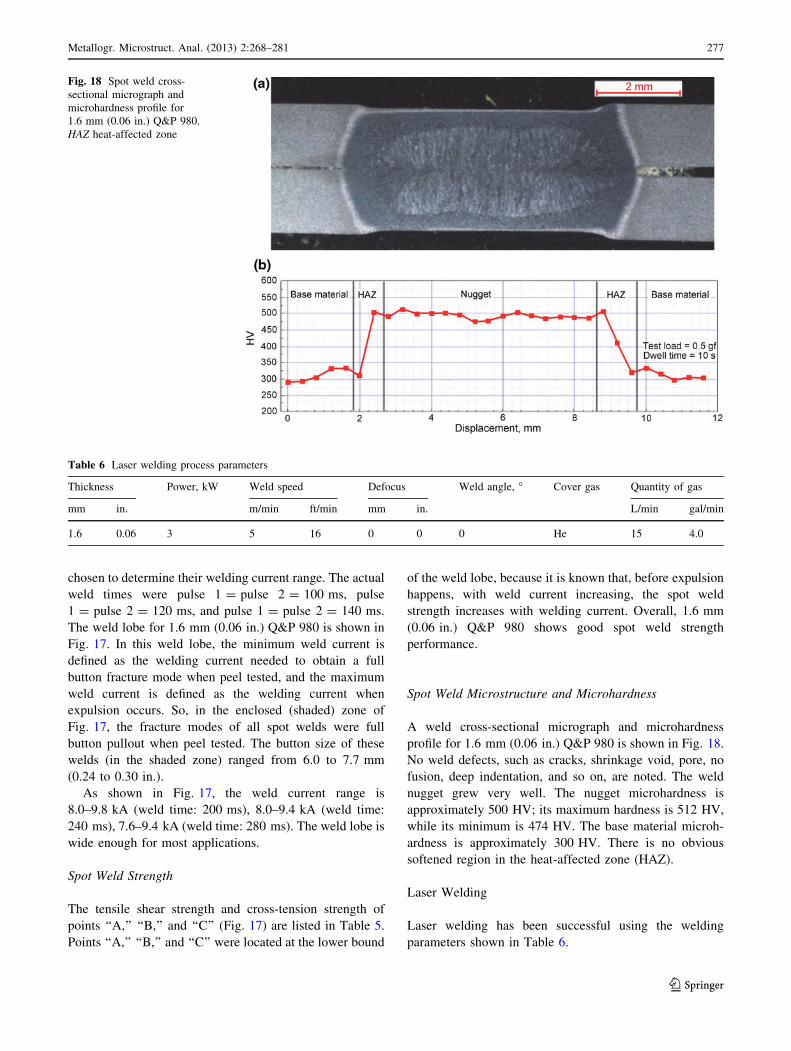
Spot Weld Microstructure and Microhardness
A weld cross-sectional micrograph and microhardness
profile for 1.6 mm (0.06 in.) Q&P 980 is shown in Fig. 18.
No weld defects, such as cracks, shrinkage void, pore, no
fusion, deep indentation, and so on, are noted. The weld
nugget grew very well. The nugget microhardness is
approximately 500 HV; its maximum hardness is 512 HV,
while its minimum is 474 HV. The base material microh-
ardness is approximately 300 HV. There is no obvious
softened region in the heat-affected zone (HAZ).
Laser Welding
Laser welding has been successful using the welding
parameters shown in Table 6.
Table 6 Laser welding process parameters
Thickness Power, kW Weld speed Defocus Weld angle, � Cover gas Quantity of gas
mm in. m/min ft/min mm in. L/min gal/min
1.6 0.06 3 5 16 0 0 0 He 15 4.0
Fig. 18 Spot weld cross-
sectional micrograph and
microhardness profile for
1.6 mm (0.06 in.) Q&P 980.
HAZ heat-affected zone
Metallogr. Microstruct. Anal. (2013) 2:268–281 277
123

Weld Joint Performance
The 1.6 mm (0.06 in.) Q&P 980 has good laser weldability.
For the welding parameters in Table 6, the laser weld joint
strength of 1.6 mm (0.06 in.) Q&P 980 was 1081 MPa
(157 ksi), and the tensile failure was located in the base
material far away from the weld seam and HAZ. Figure 19
shows the microstructure of a 1.6 mm Q&P 980 laser-welded
joint. The weld seam zone is martensite, while the HAZ is
martensite and ferrite. There were no weld defects found.
Figure 20 is the microhardness profile of the 1.6 mm Q&P
980 laser-welded joint. Microhardnesses in both the welded
seam and HAZ are higher than in the base material, and there
is no obvious softened region in the HAZ.
Fig. 19 Microstructures of 1.6 mm (0.06 in.) Q&P 980 laser-welded joint. (a) Base material. (b) Fine-grained HAZ. (c) Weld seam. (d) Coarse-
grained HAZ
Fig. 20 Microhardness profile across 1.6 mm (0.06 in.) Q&P 980 laser-welded joint. HAZ heat-affected zone
278 Metallogr. Microstruct. Anal. (2013) 2:268–281
123

The laser weld seam for Q&P 980 has good stretchability.
Figure 21 shows Erichsen cups after testing the base material
and weld seam of 1.6 mm (0.06 in.) Q&P 980. The Erichsen
test performance describes the stretchability. Using this test,
the Erichsen value for the laser weld seam was 7.34 mm
(0.29 in.), approximately 70% of the value for the base
Table 7 MAG welding process parameters
Thickness of base material Welding speed Energy input Cover gas Filler material Quantity of gas Blowpipe
distance
mm in. cm/min in./min kJ/cm Btu/in. L/min gal/min mm in.
1.6 0.06 35 14 3.6 8.7 80% Ar ? 20% CO2 ER110S 14 3.7 12 0.5
Fig. 21 Photographs of
Erichsen test specimens for
(a) base material and (b) laser-
welded seam
Fig. 22 Microhardness profile
across 1.6 mm (0.06 in.) Q&P
980 metal-active-gas-welded
joint. HAZ heat-affected zone
Metallogr. Microstruct. Anal. (2013) 2:268–281 279
123
material (10.3 mm, or 0.4 in.), and the fracture direction in
the Erichsen test was perpendicular to the laser-welded seam.
MAG Welding
MAG welding was successful using the welding parame-
ters shown in Table 7.
Weld Joint Performance
Despite the greater alloy content used for Q&P 980, there
were no more welding defects than observed with mild
steel MAG welds. For the parameters listed in Table 7, the
MAG weld strength of 1.6 mm (0.06 in.) Q&P 980 is
991 MPa (144 ksi). Figure 22 shows the microhardness
profile of the 1.6 mm Q&P 980 MAG weld joint. The
microhardness of both the welded seam and HAZ is less
than 500 HV, and there is no obvious softened region in
HAZ.
Acknowledgments The authors would like to thank Yong Zhong,
Weijun Feng, and Xinyan Jin for providing previously unpublished
data and for their assistance in the preparation of this article.
References
1. J.G. Speer, D.K. Matlock, B.C. De Cooman, J.G. Schroth, Carbon
partitioning into austenite after martensite transformation. Acta
Mater. 51, 2611–2622 (2003)
2. J.G. Speer, D.V. Edmonds, F.C. Rizzo, D.K. Matlock, Parti-
tioning of carbon from supersaturated plates of ferrite, with
application to steel processing and fundamentals of the bainite
transformation. Curr. Opin. Solid State Mater. Sci. 8, 219–237
(2004)
3. J.G. Speer, D.K. Matlock, B.C. DeCooman, J.G. Schroth, Com-
ments on ‘‘on the definitions of paraequilibrium and orthoequi-
librium’’ by M. Hillert and J. Agren, Scr. Mater., Vol 50, 2004,
p 697–699. Scr. Mater. 52, 83–85 (2004)
4. D.K. Matlock, J.G. Speer, Design considerations for the next
generation of advanced high strength sheet steels, in Proceedings
of the Third International Conference on Structural Steels, ed. by
H.C. Lee (The Korean Institute of Metals and Materials, Seoul,
2006), pp. 774–781
5. J.G. Speer, F.C. Rizzo Assuncao, D.K. Matlock, D.V. Edmonds,
The quenching and partitioning process: background and recent
progress. Mater. Res. 8, 417–423 (2005)
6. D.V. Edmonds, K. He, M.K. Miller, F.C. Rizzo, A. Clarke, D.K.
Matlock, et al., Microstructural features of quenching and parti-
tioning: a new martensitic steel heat treatment, in Fifth Interna-
tional Conference on Processing and Manufacturing of Advanced
Materials, Vancouver, 2006, ed. by T. Chandra, K. Tsuzaki, M.
Militzer, C. Ravindran, pp. 4819–4825
7. D.V. Edmonds, K. He, F.C. Rizzo, B.C. De Cooman, D.K.
Matlock, J.G. Speer, Quenching and partitioning martensite—a
novel steel heat treatment. Mater. Sci. Eng. A 438–440, 25–34
(2006)
8. K. He, D.V. Edmonds, J.G. Speer, D.K. Matlock, F.C. Rizzo,
Microstructural characterisation of steel heat-treated by the novel
quenching and partitioning process, in EMC 2008 14th European
Microscopy Congress, Aachen, Sept 1–5, 2008 (Springer, Berlin,
2008), pp. 429–430
9. S.S. Nayak, R. Anumolu, R.D.K. Misra, K.H. Kim, D.L. Lee,
Microstructure-hardness relationship in quenched and partitioned
medium-carbon and high-carbon steels containing silicon. Mater.
Sci. Eng. A 498, 442–456 (2008)
10. M.J. Santofimia, L. Zhao, R. Petrov, J. Sietsma, Characterization of
the microstructure obtained by the quenching and partitioning pro-
cess in a low-carbon steel. Mater. Charact. 59, 1758–1764 (2008)
11. C.Y. Wang, J. Shi, W.Q. Cao, H. Dong, Characterization of micro-
structure obtained by quenching and partitioning process in low alloy
martensitic steel. Mater. Sci. Eng. A 527, 3442–3449 (2010)
12. J.G. Speer, E. De Moor, K.O. Findley, D.K. Matlock, B.C. De
Cooman, D.V. Edmonds, Analysis of microstructure evolution in
quenching and partitioning automotive sheet steel. Metall. Mater.
Trans. A 42, 3591–3601 (2011)
13. G. Thomas, J. Speer, D. Matlock, J. Michael, Application of
electron backscatter diffraction techniques to quenched and par-
titioned steels. Microsc. Microanal. 17, 368–373 (2011)
14. E. De Moor, S. Lacroix, A.J. Clarke, J. Penning, J.G. Speer,
Effect of retained austenite stabilized via quench and partitioning
on the strain hardening of martensitic steels. Metall. Mater.
Trans. A 39, 2586–2589 (2008)
15. M.J. Santofimia, L. Zhao, J. Sietsma, Model for the interaction
between interface migration and carbon diffusion during
annealing of martensite–austenite microstructures in steels. Scr.
Mater. 59, 159–162 (2008)
16. M.J. Santofimia, J.G. Speer, A.J. Clarke, L. Zhao, J. Sietsma,
Influence of interface mobility on the evolution of austenite–
martensite grain assemblies during annealing. Acta Mater. 57,
4548–4557 (2009)
17. Y. Takahama, M.J. Santofimia, M.G. Mecozzi, L. Zhao, J. Sie-
tsma, Phase field simulation of the carbon redistribution during
the quenching and partitioning process in a low-carbon steel.
Acta Mater. 60, 2916–2926 (2012)
18. D.K. Matlock, J.G. Speer, Processing opportunities for new
advanced high-strength sheet steels. Mater. Manuf. Process. 25,
7–13 (2010)
19. G.A. Thomas, J.G. Speer, D.K. Matlock, Considerations in the
application of the quenching and partitioning concept to hot
rolled AHSS production. Iron Steel Technol. 5, 209–217 (2008)
20. G.A. Thomas, J.G. Speer, D.K. Matlock, Quenched and partitioned
microstructures produced via Gleeble simulations of hot-strip mill
cooling practices. Metall. Mater. Trans. A 42, 3652–3659 (2011)
21. L. Wang, W. Li, W. Feng, Industry trials of C–Si–Mn steel
treated by Q&P concept in Baosteel. Presented at SAE Interna-
tional Congress, Detroit, 2010
22. L. Wang, X. Jin, H. Qian, Recent development of galvanizing
sheet steels in Baosteel, in Proceedings of Galvatech 2011:
Eighth International Conference on Zinc and Zinc Alloy Coated
Sheet Steel, Genova, 2011
23. L. Wang, W. Feng, Development and application of Q&P sheet
steels, in Advanced Steels: The Recent Scenario in Steel Science
and Technology, ed. by W. Yuqing, D. Han, G. Yong (Springer,
New York, 2011), p. 255
24. A.W. Hudgins, Shear fracture in bending of advanced high
strength steels, Ph.D. thesis, MT-SRC-010-008, Colorado School
of Mines, Golden, 2010
25. D.K. Matlock, J.G. Speer, in Third Generation of AHSS:
Microstructure Design Concepts, ed. by A. Haldar, S. Suwas, D.
Bhattacharjee (Springer, London, 2009), p. 185
26. J.G. Speer, A.M. Streicher, D.K. Matlock, F. Rizzo, G. Krauss,
Austenite Formation and Decomposition, ed by E.B. Damm, M.J.
Merwin (TMS, Warrendale, 2003), p. 505
27. A.J. Clarke, Ph.D. thesis, Colorado School of Mines, Golden,
2006
280 Metallogr. Microstruct. Anal. (2013) 2:268–281
123

28. M.J. Santofimia, L. Zhao, J. Sietsma, Microstructural evolution of
a low-carbon steel during application of quenching and parti-
tioning heat treatments after partial austenitization. Metall.
Mater. Trans. A 40, 46–57 (2009)
29. S. Zaefferer, J. Ohlert, W. Bleck, A study of microstructure,
transformation mechanisms and correlation between
microstructure and mechanical properties of a low alloyed TRIP
steel. Acta Mater. 52, 2765–2778 (2004)
30. T. Bhattacharyya, S.B. Singh, S. Das, A. Haldar, D. Bhatta-
charjee, Development and characterisation of C–Mn–Al–Si–Nb
TRIP aided steel. Mater. Sci. Eng. A 528, 2394–2400 (2011)
Metallogr. Microstruct. Anal. (2013) 2:268–281 281
123


![Martensite Transformation In Sandvik Nanoflex · influence the martensite transformation [5]. Later on, the martensite fraction will be investigated that is why the martensite is](https://img.dokumen.tips/doc/110x75/5f10b9bc7e708231d44a845d/martensite-transformation-in-sandvik-influence-the-martensite-transformation-5.jpg)