Embed Size (px)
Citation preview

ObjectivesAfter completing this chapter, you will be able to:
❒ Identify types and grades of steel and steel alloys.
❒ Identify shapes and forms of steel and steel alloys.
❒ Select the appropriate steel filler based on the steel to be welded.
❒ Explain joint preparation, weld backing, and preheating for steels.
❒ Recall welding procedures and techniques for welding steel using DCEN.
❒ Recall correct torch positioning for various types of welds.
❒ Differentiate between stringer beads and weave beads.
❒ Recognize groove and fillet weld defects.
❒ Recall factors that influence postweld treatment.
Key Termsannealingcastingchromium-molybdenum steelsforgingheat treatingmartensitequenchingstringer beadstemperingtravel angleweave beadswettedwork angle
IntroductionThe GTAW technique required for a given job
depends on many factors, including the weld joint design. Welders must constantly monitor and adjust many critical variables in order to produce a high-quality weld. The effects of these variables can be seen in the behavior of the weld pool as the weld is being made. Welding skill is acquired by practice, practice, and more practice. Changing one variable at a time is the best way to determine what the weld needs.
The following questions should be considered when practicing welding:
• Is the weld the right size?• Is the weld too high or too low?• Is the proper travel speed being used?• Is the torch angle correct?• Is the welding rod being held at the proper
angle?• Is the weld pool flowing properly?• Is the current (amperage) correct?• Is the voltage (arc length) correct?• Is the weld in the proper location?• Is the fillet weld leg the proper size?Also, it is important to remember to fill the crater
at the end of the weld and hold the torch over the end of the weld until it cools. This allows the postflow of shielding gas to protect the hot metal.
127
Chapter
Manual Welding Techniques
This sample chapter is for review purposes only. Copyright © The Goodheart-Willcox Co., Inc. All rights reserved.
128 Gas Tungsten Arc Welding Handbook
Base Materials (Steel)Many types and grades of steel are included in
the steel family. These materials are typically magnetic and melt at approximately 2500°F (1371°C).
Carbon SteelsCarbon steels are identified as a group that
contains the following materials:• Carbon—1.70% maximum• Manganese—1.65% maximum• Silicon—0.60%Carbon steels are further classified as low, mild,
medium, and high carbon:• Low-carbon steel—less than 20% carbon• Medium-carbon steel—0.20%–0.50% carbon• High-carbon steel—over 50% carbon
Low-Alloy SteelsLow-alloy steels contain varying amounts of
carbon and a variety of alloying elements. These elements include chromium, molybdenum, nickel, vanadium, and manganese. These elements increase the strength and toughness of the material and, in some cases, increase resistance to corrosion.
Heat-Treated MaterialsHeat-treated steels are used for many different
applications. Heat treating is a process in which the material is heated and cooled to specific temperatures for specific amounts of time. A material is heat treated to obtain desirable qualities or to reduce undesir-able qualities. Many materials and alloys, including aluminum, copper, titanium, nickel, and chromium-molybdenum, can be heat treated to make the material perform in different ways. Heat treating of a material is most commonly done as part of the manufacturing process.
Quenching is the process of rapidly cooling a mate-rial to obtain certain material properties that increase the material’s toughness. The quenching process changes the crystalline structure of the material.
Tempering is a heat treatment that can improve the mechanical properties of a material. Tempering involves heating the metal to a certain temperature below the material’s melting temperature for a certain length of time. This process allows trapped carbon to produce a different crystalline structure. The material is then cooled at a controlled rate to a low temperature. The temperature and the duration of the tempering
process determine which mechanical properties will be enhanced.
Annealing is a heat treatment that involves heating the material to a temperature that rearranges the crystalline structure and reduces internal stress of the material, making the material softer and more ductile. Annealing is typically done to improve the cold working properties of a material.
Tool SteelsTool steels are steels with a combination of high
carbon and alloy content. Tool steels are used for making dies, cutting bits, and many other types of tools. Dies and other tools are formed from annealed tool steel. Later in the manufacturing process, after the tools are formed, the metal is treated to harden or temper the metal as needed.
The various types of tool steel include W1, W2, SI, S5, S7, 01, 06, A2, A4, and D2. Also included are H11, H12, H13, and M1, M2, M10. The numbers for the various tool steels identify the various compositions. The letters usually indicate the type of quenching required to achieve full mechanical values.
Forms and Shapes of SteelSteel is supplied in many forms and shapes for
welding. Some of the more common shapes are hot-rolled steel, cold-rolled steel, castings, and forgings.
Hot-Rolled SteelHot-rolled steel includes plate and structural
forms which are allowed to cool in air after rolling. After cooling, the oxide film on the surface is light blue in color.
Cold-Rolled SteelThis material is final-rolled to the required
dimensions in the cold condition and does not have an oxide film on the surface. A light coating of oil is placed on the material to prevent rusting.
CastingsCasting refers to pouring molten metal into a
mold that has the desired shape. The metal is kept in the mold until it solidifies, at which point the mold is removed. The cast metal inside has the same shape as the inside of the mold. Castings are usually made in a sand mold and have a rough surface. New castings are sandblasted, leaving a dull silver surface.
Chapter 8 Manual Welding Techniques 129
ForgingsForging refers to pressing a shaped die into
hot metal under high pressure. The metal is heated to a plastic state before it is forged so it will take on the shape of the die that is pressed into it. Forgings are made from billets, bars, round stock, or square stock. Forgings can be identified by the remnants of the flashing usually extending around the center of the part. Since the forging operation is done while the part is hot, a scale forms on the surface, similar to the scale on hot-rolled steel.
Steel ClassificationsSteels are manufactured to specifications devel-
oped by various organizations, including ASTM International. One grouping of steels under this clas-sification is ASTM A335. The assigned designation identifies the material as high-ferritic steel alloy pipe for high-temperature applications. Other steel specifi-cations include SAE International’s Aerospace Mate-rial Specifications (AMS), the American Iron and Steel Institute (AISI) classifications, and corporation specifications.
Filler MetalsFiller metals used to join carbon steels, low-alloy
steels, and tool steels must be selected to produce the desired mechanical properties of the weldment after any required welding or heat treatment. Carbon and low-alloy steel filler metals are selected from specifi-cations, such as AWS A5.18, AWS A5.28, MIL-E-23765, MIL-S-6758, and AMS6370.
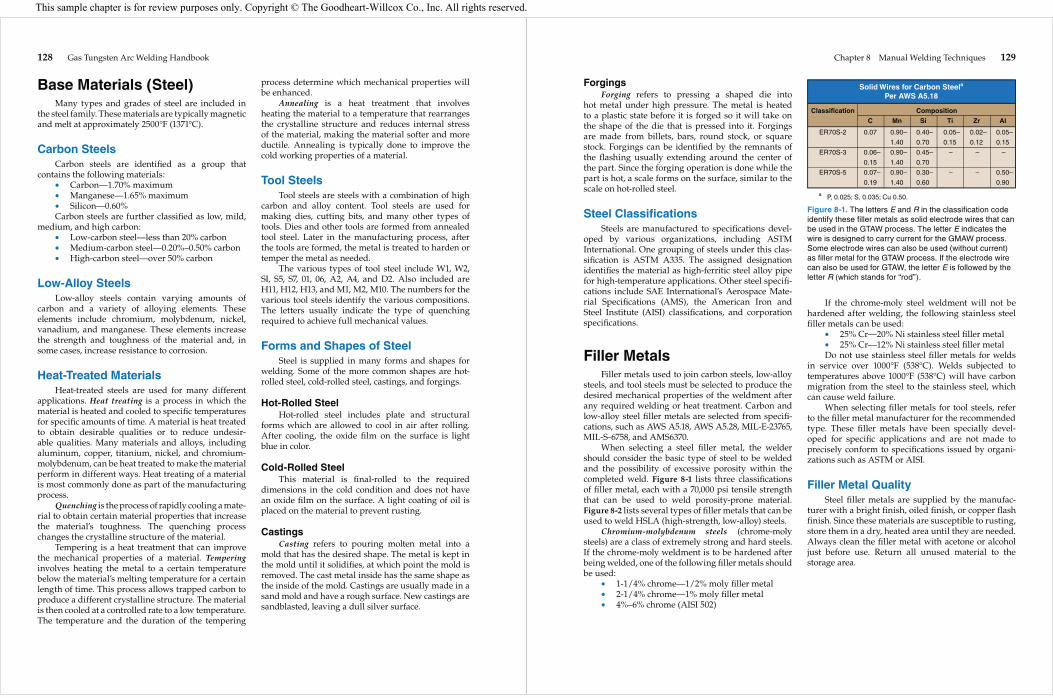
When selecting a steel filler metal, the welder should consider the basic type of steel to be welded and the possibility of excessive porosity within the completed weld. Figure 8-1 lists three classifications of filler metal, each with a 70,000 psi tensile strength that can be used to weld porosity-prone material. Figure 8-2 lists several types of filler metals that can be used to weld HSLA (high-strength, low-alloy) steels.
Chromium-molybdenum steels (chrome-moly steels) are a class of extremely strong and hard steels. If the chrome-moly weldment is to be hardened after being welded, one of the following filler metals should be used:
• 1-1/4% chrome—1/2% moly filler metal• 2-1/4% chrome—1% moly filler metal• 4%–6% chrome (AISI 502)
If the chrome-moly steel weldment will not be hardened after welding, the following stainless steel filler metals can be used:
• 25% Cr—20% Ni stainless steel filler metal• 25% Cr—12% Ni stainless steel filler metalDo not use stainless steel filler metals for welds
in service over 1000°F (538°C). Welds subjected to temperatures above 1000°F (538°C) will have carbon migration from the steel to the stainless steel, which can cause weld failure.
When selecting filler metals for tool steels, refer to the filler metal manufacturer for the recommended type. These filler metals have been specially devel-oped for specific applications and are not made to precisely conform to specifications issued by organi-zations such as ASTM or AISI.
Filler Metal QualitySteel filler metals are supplied by the manufac-
turer with a bright finish, oiled finish, or copper flash finish. Since these materials are susceptible to rusting, store them in a dry, heated area until they are needed. Always clean the filler metal with acetone or alcohol just before use. Return all unused material to the storage area.
Solid Wires for Carbon Steela
Per AWS A5.18
Classification Composition
C Mn Si Ti Zr Al
ER70S-2 0.07 0.90– 0.40– 0.05– 0.02– 0.05–
1.40 0.70 0.15 0.12 0.15
ER70S-3 0.06– 0.90– 0.45– – – –
0.15 1.40 0.70
ER70S-5 0.07– 0.90– 0.30– – – 0.50–
0.19 1.40 0.60 0.90
a P, 0.025; S, 0.035; Cu 0.50.
Figure 8-1. The letters E and R in the classification code identify these filler metals as solid electrode wires that can be used in the GTAW process. The letter E indicates the wire is designed to carry current for the GMAW process. Some electrode wires can also be used (without current) as filler metal for the GTAW process. If the electrode wire can also be used for GTAW, the letter E is followed by the letter R (which stands for “rod”).
This sample chapter is for review purposes only. Copyright © The Goodheart-Willcox Co., Inc. All rights reserved.

130 Gas Tungsten Arc Welding Handbook
Solid Wires for HSLA Steel Per AWS 15.28
Classification Compositiona,b Characteristics,
Applications
C Mn Si P S Ni Cr Mo V Cu
Cr-Mo ER80S-B2 0.07– 0.12
Use to weld 1/2 Cr-1/2 Mo, 1 Cr-1/2 Mo, 1-1/4 Cr-1/2 Mo steels for high- temperature and corrosive service and for Cr-Mo to carbon-steel welds.
Lower carbon content improves resistance to cracking. Use where postweld heat treatment is not performed.
Use for 2-1/4 Cr-1 Mo steel for high-temperature high-pressure piping and vessels. For all Cr-Mo-to-carbon-steel joints.
Lower carbon content improves resistance to cracking. Use where postweld heat treatment is not performed.
Use to weld HSLA steels and nickel steels up to 3-1/2%. Gives high strength and good toughness down to -100°F (-73°C).
High Mn and Si contents reduce porosity. For single and multipass welding of carbon and low-alloy steels. Use on S-bearing (free machining) steel. Farm implements, auto parts, light-gauge steel, AISI 4130, T-1.
High-strength, tough weld metal for critical welds. HY80, HY100 and higher-strength steels, structural applications for service as low as -60°F (-51°C).
ER80S-B2L 0.05 0.40– 0.40– 0.025 0.025 0.20 1.20– 0.40– – 0.35 0.70 0.70 1.50 0.65
ER90S-B3 0.07– 2.30– 0.90– 0.12 2.70 1.20
ER90S-B3L 0.05 2.30– 0.90– 2.70 1.20
Ni steelER80S-Ni3 0.12 1.25 0.40– 0.25 0.25 3.00– – – – – 0.80 3.75
Mn-MoER80S-D2 0.07– 1.60– 0.50– 0.025 0.025 0.15 – 0.40– – 0.50 0.12 2.10 0.80 0.60
Otherd
ER100S-1 0.08 1.25– 0.20– – – 1.40– 0.30 0.25– 0.05 0.25 1.80 0.50 2.10 0.55
ER100S-2 0.12 1.25– 0.20– 0.010 0.010 0.80– 0.30 0.20– 0.05 0.35– 1.80 0.60 1.25 0.55 0.65
ER110S-1 0.09 1.40– 0.20– 1.90– 0.50 0.25– 0.04 0.25 1.80 0.55 2.60 0.55
ER120S-1 0.10 1.40– 0.25– 2.00– 0.60 0.30– 0.03 0.25 1.80 0.60 2.80 0.65
ERXXS-Gc
1.20– 0.40–1.50 0.65
a. As manufactured.
b. Total other elements, 0.50.
c. Minimum 0.50 nickel, 0.30 chromium, or 0.20 molybdenum.
d. Ti, Zr, Al, 0.10 each, except –G wires.
Figure 8-2. The letters HSLA identify the steels as high-strength, low-alloy materials.
Chapter 8 Manual Welding Techniques 131
Joint PreparationJoint edges prepared by thermal cutting processes
have a heavy oxide film on the surface, as shown in Figure 8-3. This oxide should be completely removed prior to welding in order to prevent porosity in the weld metal.
Joint edges prepared by shearing should be sharp without tearing or ridges. Otherwise, dirt or oil can become trapped in the joint and result in faulty welds. Rough edges can be removed prior to welding with a light grinding.
Weld Backing for SteelGroove welds that are welded from one side of
the joint, where 100% penetration is required, can be backed with argon gas or a solid bar. Solid bars can be made of copper or stainless steel.
Excluding air from the backside or penetration side of the joint will assist in wetting of the penetra-tion. A wetted penetration has a smooth junction and even flow of the penetration onto the base metal. The exclusion of air also prevents the formation of scale and oxide.
Preheating SteelsCarbon steels less than 1″ (25.4 mm) thick and
with less than .30% carbon generally do not require preheat. Welding on highly restrained joints is an exception. These joints should be preheated to 50°–100°F (10°–38°C) to minimize shrinkage cracks in the base metal and the weld deposit.
Low-alloy steels, such as the chrome-moly steels, have hard heat-affected zones after welding if the preheat temperature is too low. The hard heat-affected zones are caused by the rapid cooling rate of the base material and the formation of martensitic grain struc-tures. A 200°–400°F (93°–204°C) preheat temperature
slows down the cooling rate and prevents the forma-tion of a martensitic structure.
Martensite is a metallurgical term that defines a type of grain structure obtained by heating and quenching. The martensitic grain structure makes the metal hard. Parts that are welded are, in effect, heated and quenched. If the carbon content of the material is sufficient, and the preheat temperature is too low, the material in the heat affected zone will harden during welding. This results in high tensile properties with very low ductility. The formation of hard martensite-type grains increases the possibility of cracking as the weld metal cools and shrinks.
Tool steels have a very high carbon content and are prone to cracking in the heat-affected zone without sufficient preheat. Figure 8-4 lists some recommended preheat temperature ranges for welding tool steels.
Quenched and tempered steel requires preheat and interpass temperature control to retain the orig-inal mechanical properties of the metal. The manu-facturer’s recommendations for these temperatures should be strictly followed.
Torch Angles and Bead Placement
Proper manipulation of the welding torch is very important in making a good weld. The torch is usually held like a pencil, as shown in Figure 8-5. When welding is done in the flat position, the hand should be placed lightly on a surface, so the hand can
Figure 8-3. The oxide scale and small gouge indentations were formed on this piece of metal by the oxyacetylene cutting process. (Mark Prosser)
Annealed Base Hardened Base Material Material Preheat Material Preheat Type and Postheat and Postheat Temperature Temperature
W1, W2 250–450°F (121–232°C) 250–450°F (121–232°C)
S1 300–500°F (149–260°C) 300–500°F (149–260°C)
S5 300–500°F (149–260°C) 300–500°F (149–260°C)
S7 300–500°F (149–260°C) 300–500°F (149–260°C)
01 300–400°F (149–204°C) 300–400°F (149–204°C)
06 300–400°F (149–204°C) 300–400°F (149–204°C)
A2 300–500°F (149–260°C) 300–400°F (149–204°C)
A4 300–500°F (149–260°C) 300–400°F (149–204°C)
D2 700–900°F (371–482°C) 700–900°F (371–482°C)
H11, H12, H13 900–1200°F (482–649°C) 700–1000°F (371–538°C)
M1, M2, M10 950–1100°F (510–593°C) 950–1050°F (510–566°C)
Figure 8-4. Thoroughly preheat the part to be welded to the required temperature. Do not allow the part to cool below the minimum temperature until postheat is complete.
This sample chapter is for review purposes only. Copyright © The Goodheart-Willcox Co., Inc. All rights reserved.

132 Gas Tungsten Arc Welding Handbook
move across the joint evenly. Movement of the torch by the fingers alone usually results in incorrect torch angles and a poor weld.
Torch angles are very important to maintain and understand. The torch angles control the heat of the arc, and the weld pool will move where it is directed by the torch angles. Two different torch angles, the
work angle and the travel angle, greatly affect how the weld bead is placed into the weld joint.
The work angle is the angle of the torch in a plane that is perpendicular to the weld axis and is measured from the perpendicular position to the torch’s actual position. See Figure 8-6A. Work angles usually split the weld pool evenly between the two pieces of base metal. When the work angle points to one side of the joint more than the other, the weld will move in that direction. For example, on a flat butt joint, the work angle is 90°, straight up and down into the joint. Work angles are generally straight into the middle of the joint. The weld pool will show if the weld is favoring one side or the other. When this happens, the welder must adjust the work angle to correct the uneven weld.
The travel angle is the angle of the torch in the plane parallel to the weld axis and is measured from the perpendicular position to the torch’s actual posi-tion. See Figure 8-6B. The torch should always be pushed in the direction of the weld. Torch travel angles are usually 15° to 20°. The main reason to main-tain a good travel angle is so that the welder can see the weld pool. The welder must be able to see the weld pool when making any weld. The actual weld pool is much smaller than the ceramic cup on the end of the torch, so the torch must be laid over so the weld pool can be seen. However, travel angles that are too severe can suck air into the weld from the back side, causing porosity or other discontinuities due to atmospheric contamination.
For welding butt joints in any position, the suggested work angle is generally 90°. Because the work angle is perpendicular to the workpiece, it provides maximum penetration. The suggested travel angle for welding butt joints is typically a push angle
Figure 8-5. Holding the torch in the manner shown allows the welder to move the torch easily to change torch angles. (Mark Prosser)
Work angle
Fillerrod angle
Travel angle
End View Side View
Figure 8-6. Welders must be mindful of the travel angle, work angle, and filler rod angle. A—This end view of a fillet weld in progress shows how the work angle is measured. B—This side view of a fillet weld in progress shows how travel angle and filler rod angle are measured.
Chapter 8 Manual Welding Techniques 133
of 15°–20°. The term push angle refers to the torch being pointed in the direction the weld progresses. This angle allows the welder to see the weld pool, but still provides good penetration. A larger travel angle would create an elongated weld pool and decrease the penetration into the joint. The welding rod is typically held 10°–20° from the surface of the base metal. This angle makes it easy for the welder to see the weld pool and to feed welding rod into the weld pool as needed. See Figure 8-7.
When making fillet welds, the torch is generally held at a 45° work angle and a 15°–20° travel angle. If an inside corner joint is being welded, the tip of the electrode is pointed directly at the joint between the two workpieces. If a lap joint is being welded, the tip of the electrode should be pointed slightly more toward the surface piece than the edge piece. The edges of a metal plate are not able to dissipate heat as
quickly as the large surfaces of the plate. As a result, if the torch is pointed directly at the joint between the two plates, the edge of one piece heats up faster than the surface of the other, which can lead to undercut-ting at the edges of the joint. Pointing the torch slightly more toward the surface than the edge provides even heating through the entire joint. See Figure 8-8.
When adding welding rod, the welder should grip the rod in the fingers as shown in Figure 8-9. The hand should be kept as close as possible to the arc to hold the rod steady. The rod should be moved in conjunc-tion with the torch movement. When additional rod is required, it can be moved forward through the fingers using a forward movement of the thumb. Too much extension of the welding rod from the fingers results in a wobbly rod end, making addition to the weld pool very uneven. Adding rod to the pool requires steadi-ness and concentration in order to place the correct
A
B C
Figure 8-7. Typical welding angles for welding a butt joint in any position. A—This butt weld is in the flat position. Note that the torch is at a 90° work angle. The torch is tilted so the electrode is pointing in the direction the weld is progressing. This is referred to as the travel angle. B—A butt weld in the horizontal position. C—A butt weld in the vertical position. (Mark Prosser)
This sample chapter is for review purposes only. Copyright © The Goodheart-Willcox Co., Inc. All rights reserved.

134 Gas Tungsten Arc Welding Handbook
amount of material at the right place at exactly the right time. A 10°–20° entrance angle of the rod into the weld pool should always be maintained.
Types of Beads/PassesWelds made without any side-to-side movement
(oscillation) of the torch are called stringer beads, or stringer passes. Welds made with side-to-side move-ment of the torch are called weave beads. When a weave bead is being made, filler metal should be added at the edges of the weld pool to prevent under-cutting. Figure 8-10 compares a stringer bead and a weave bead. A technique known as walking, or rocking, the cup is commonly used to create a weave pattern in V-groove butt joints in thicker sections of material. In this oscillation technique, the cup of the torch is actually set on the base metal and rocked back and forth, much like moving a refrigerator across the floor. Walking or rocking the cup to make a weave pattern takes a great deal of practice and determination.
A B
Figure 8-8. The proper work and travel angles for making fillet welds. A—Proper angles for T-joints and inside corner joints. B—Proper angles for lap joints. (Mark Prosser)
Figure 8-9. Welding rod held in this manner can be added to the weld pool as needed. (Mark Prosser)
A B
Figure 8-10. A stringer bead (A) is narrower than a weave bead (B). (Mark Prosser)
Chapter 8 Manual Welding Techniques 135
Welding Steels Using DCEN (Straight) Polarity
DCEN polarity is used for welding steels because the higher concentration of heat input into the base material results in deeper penetration. DCEN polarity is the best option for obtaining full penetration welds and controllable weld bead profiles. With DCEN polarity, two-thirds of the arc’s heat is concentrated on the workpiece and one-third is concentrated on the electrode. Since the majority of the heat is concen-trated on the work and not on the electrode, smaller electrodes can be used without worrying about elec-trode deterioration.
Electrodes Used on SteelsFor a long time, 1% or 2% thoriated electrodes
were recommended for welding steel. When thorium is added to tungsten in small amounts, it increases the electrode’s current-carrying capabilities. Thoriated electrodes do not work well with ac current and are not recommended for use with the newer inverter-type machines. If thoriated electrodes are overheated, the end of the electrode can begin to vaporize and spit small amounts of the electrode into the weld. Grinding thoriated tungsten electrodes results in radioactive dust that can be hazardous. These electrodes usually have a yellow or red color band near the top of the electrode, depending on the percentage of thorium.
Today, electrodes with more desirable character-istics are available. Lanthanated tungsten electrodes are relatively new to the US, but are becoming more popular. Lanthanum is a “rare earth” material that is not radioactive. Lanthanated electrodes work well for ac or dc currents, have good current-carrying capaci-ties, and can be used universally, eliminating the confusion of selecting an electrode. Lanthanated elec-trodes usually have a black color band near the top of the electrode.
Other types of electrodes, such as ceriated, zirco-niated, and pure tungsten, all have some desirable traits. Ceriated tungstens usually have an orange color band, zinconiated tungstens usually have a brown color band, and pure tungstens usually have a green color band. Research the base materials to be welded to determine which electrode is best suited for your application. More detailed information about different electrode types and when they should be used was presented in Chapter 3, Auxiliary Equipment and Systems.
Amperage ranges must be considered when selecting the size of the electrode. Higher welding amperages require larger electrodes.
When preparing an electrode for welding steel, keep in mind that different tip configurations will result in different bead profiles. For welding steel, it is generally recommended to sharpen the electrode to a point and make a slight flattened tip. Pointed tips direct the arc in a more concentrated area. Flattening the very tip of the electrode helps concentrate the arc even more.
Shielding Gases for GTAW on SteelsPure argon gas can be used when welding metal
up to 1/8″ (3.2 mm) thick. When thicker materials are being welded, helium should be added to the shielding gas to improve weld pool control and pene-tration. Helium increases the temperature of the arc, resulting in deeper penetration. The following stan-dard shielding gas mixes can be used:
• 75% argon–25% helium• 50% argon–50% helium• 25% argon–75% heliumPure helium gas can be used for automatic
welding of steel or steel alloys. Gas purity must be sufficient to prevent hydrogen pickup. Hydrogen will cause porosity and cracking.
Techniques for Welding Steels and Steel Alloys 1. Clean the oxide scale from the weld joint imme-
diately prior to welding. Clean the entire weld area to bright metal.
2. Select a welding rod that has the required prop-erties. When welding porosity-prone material, always use a welding rod that contains deoxi-dizers to prevent porosity.
3. Preheat low-alloy steels and tool steels to prevent cracking in the weld and heat-affected zones.
4. Weld porosity-prone materials by maintaining the arc on the molten metal. Do not hold the arc on the base metal. On crack-sensitive materials, do not make concave welds. These welds are prone to cracking through the centerline.
5. On multipass welds, always remove any scale on the surface of each pass to reduce the possibility of oxide entrapment.
6. Always fill craters on crack-sensitive materials. 7. When welding tool steels, make small stringer
beads, (Figure 8-10A), to reduce the expansion of the base metal and prevent cracking. Imme-diately after welding, the weld metal can be peened to reduce shrinkage as the metal cools.
This sample chapter is for review purposes only. Copyright © The Goodheart-Willcox Co., Inc. All rights reserved.

136 Gas Tungsten Arc Welding Handbook
Welding Procedure Specifications (WPS)
The following eleven procedures have been devel-oped for GTAW practice and production. Any scrap material can be used for practice. The weld joint should fit properly for good results. Clean all of the materials, as previously discussed, before tack welding and welding.
When steel is being welded, a small white dot may form on the weld pool surface. This is a normal condition and does not require any corrective action. The material in the dot is silicon, which separates from the base material and the welding rod. It floats on the surface because it is lighter than the metal.
Gas nozzle sizes are not specified, since many variables are involved. Always use the largest possible size. However, do not use a size that will obstruct your view of the weld pool.
Tooling can be used when welding practice plates. Tools assist in holding the material in the proper plane and prevent warpage and misalignment during the welding sequence. The tooling may also have a gas manifold to permit use of a backing gas, if desired. See Figure 8-11.
Welding Procedure Number 8-1
Weld joint type: Flat plate autogenous weldPosition: FlatMaterial type: Cold-rolled steel
Thickness: 1/16″ (1.6 mm)Machine setup: DCEN high-frequency startShielding gas: Argon
CFH: 15–25Tungsten type: 1%, 1.5%, or 2% lanthanated,
ceriated, or thoriatedDiameter: 1/16″ (1.6 mm) (tapered)
Procedure: 1. Prepare and clean the materials. 2. Raise the part to be welded 1/8″ (3.2 mm) above
the table with metal blocks. 3. Align the torch to the angles shown in Figure 8-12
(90° work angle and 15°–25° travel angle) and lower the torch until the tip of the electrode is approximately 1/8″ (3.2 mm) from the top surface.
4. Start the arc at low current; lower the torch until the electrode tip is approximately 1/16″ (1.6 mm) from the surface.
A
B
Figure 8-11. Tooling can support the weld and provide backing gas. A—Hand-built copper backing plates for providing cover gas to the back side of a butt weld. The weld is positioned on top of the plate and welded. B—This fixture includes a manifold for backing gas. The weldment is clamped and held in place by the top bars. (Mark Prosser)
Chapter 8 Manual Welding Techniques 137
5. Increase the amperage and form a weld pool approximately 3/16″ (4.8 mm) in diameter.
6. Move the torch forward while:A. Maintaining the weld pool size.B. Maintaining the torch height.C. Maintaining the torch angles.
7. Stop the weld at the end of the plate.A. Do not lift the torch away from the plate.
Postflow gas will protect the hot metal during the cooling period.
Problem Areas and Corrections 1. Uneven top weld width and depression.
Possible cause: Variation in welding speed.Solution: Maintain a consistent travel speed.Possible cause: Heat buildup in the weld pool.Solution: Maintain travel speed to reduce heat.
2. Uneven contour.Possible cause: Incorrect torch angle.Solution: Align the torch vertically over the weld.
3. Uneven penetration or lack of penetration.Possible cause: Insufficient amperage.Solution: Increase amperage.Possible cause: Variable torch height.Solution: Keep the torch the same height above
the weld pool.Possible cause: Variable travel speed.Solution: Maintain a travel speed that keeps the
weld pool a consistent size.
Welding Procedure Number 8-2
Weld joint type: Bead on platePosition: FlatMaterial type: Cold-rolled steel
Thickness: 1/16″ (1.6 mm)Filler metal: ER70S-2 or 6
Diameter: .045″ (1.1 mm)Machine setup: DCEN high-frequency startShielding gas: Argon
CFH: 15–25Tungsten type: 1%, 1.5%, or 2% lanthanated,
ceriated, or thoriatedDiameter: 1/16″ (1.6 mm) (tapered)
Procedure: 1. Prepare and clean the materials. 2. Raise the part to be welded 1/8″ (3.2 mm) above
the table with metal blocks. 3. Align the torch to the angles shown in Figure 8-13
and lower the torch until the electrode tip is approximately 1/8″ (3.2 mm) from the top surface.Figure 8-12. Torch position for an autogenous weld in the
flat position. (Mark Prosser)
Figure 8-13. Torch and welding rod positions for running a bead on a plate in the flat position. (Mark Prosser)
This sample chapter is for review purposes only. Copyright © The Goodheart-Willcox Co., Inc. All rights reserved.
138 Gas Tungsten Arc Welding Handbook
4. Hold the welding rod as shown in Figure 8-13 and move it so the end is approximately 1″ (25.4 mm) from the electrode.
5. Start the arc at low current. Lower the torch so the electrode tip is approximately 1/16″ (1.6 mm) from the surface.
6. Increase the amperage and form a weld pool approximately 1/4″ (6.5 mm) in diameter.
7. Bring the rod into the front edge of the pool and melt enough rod to form a slight crown on the surface.
8. Draw the rod approximately 1/2″ (12.7 mm) away from the pool.
9. Move the torch forward approximately 3/16″ (4.8 mm) and add rod again as in Step 7.
10. Continue moving the arc across the joint, adding rod as before.
11. Stop the weld at the end of the plate. Remember to hold the torch at the end until the weld cools. This protects the weld with shielding gas as it cools.
Problem Areas and Corrections: 1. Uneven top weld width and low crown.
Possible cause: Variation in travel speed.Solution: Maintain a consistent travel speed.Possible cause: Heat buildup in the weld pool.Solution: Increase the travel speed as the plates
get hotter.Possible cause: Variation in adding rod.Solution: Add rod to form a consistent crown.
2. Undercut.Possible cause: Torch not aligned vertically.Solution: Maintain a 90° work angle.Possible cause: Not enough filler metal added to
the weld pool.Solution: Add rod to the center of the weld pool.
3. Penetration uneven or lack of penetration.Possible cause: Inconsistent travel speed.Solution: Maintain a consistent travel speed.Possible cause: Inconsistent rod addition.Solution: Add filler metal to create a consistent
crown on the weld pool.Possible cause: Insufficient amperage.Solution: Increase amperage and add more
welding rod.Possible cause: Inconsistent torch height.Solution: Hold the torch at a consistent height.
Welding Procedure Number 8-3
Weld joint type: Square-groove buttPosition: FlatMaterial type: Cold-rolled steel
Thickness: 1/16″ (1.6 mm)Filler metal: ER70S-2 or 6
Diameter: .045″–.062″ (1.1 mm – 1.6 mm)Machine setup: DCEN high-frequency startShielding gas: Argon
CFH: 15–25Tungsten type: 1%, 1.5%, or 2% lanthanated,
ceriated, or thoriatedDiameter: 1/16″ (1.6 mm) (tapered)
Procedure: 1. Prepare and clean the materials. 2. Tack weld the plates together. 3. Raise the part to be welded 1/8″ (3.2 mm) above
the table with metal blocks. 4. Align the torch to the angles shown in Figure 8-14
and lower the torch until the electrode tip is approximately 1/8″ (3.2 mm) from the surface.
5. Position the end of the welding rod approximately 1″ (25.4 mm) from the electrode.
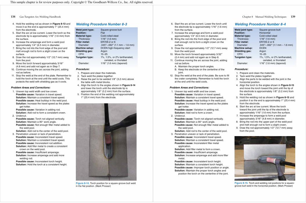
Figure 8-14. Torch position for a square-groove butt weld in the flat position. (Mark Prosser)
Chapter 8 Manual Welding Techniques 139
6. Start the arc at low current. Lower the torch until the electrode tip is approximately 1/16″ (1.6 mm) from the surface.
7. Increase the amperage and form a weld pool approximately 1/4″ (6.5 mm) in diameter.
8. Bring the rod into the front edge of the pool and melt enough rod to form a slight crown on the surface.
9. Draw the rod approximately 1/2″ (12.7 mm) away from the weld pool.
10. Move the torch forward approximately 3/32″ (2.4 mm) and add rod again as in Step 8.
11. Continue moving the arc across the joint, adding rod as before.A. Maintain the proper torch angles.B. Keep the electrode on the centerline of the
joint. 12. Stop the weld at the end of the plate. Be sure to fill
the crater completely. Remember to hold the torch at the end until the weld cools.
Problem Areas and Corrections: 1. Uneven top weld width and low crown.
Possible cause: Variation in travel speed.Solution: Maintain a consistent travel speed.Possible cause: Heat buildup in the weld pool.Solution: Increase the travel speed as the plates
get hotter.Possible cause: Variation in adding rod.Solution: Add rod to form a crown.
2. Undercut.Possible cause: Torch not aligned vertically.Solution: Maintain a 90° work angle.Possible cause: Not enough filler metal added to
the weld pool.Solution: Add rod to the center of the weld pool.
3. Penetration uneven or lack of penetration.Possible cause: Inconsistent travel speed.Solution: Maintain a consistent travel speed.Possible cause: Inconsistent filler metal
application.Solution: Add filler metal to form a crown.Possible cause: Insufficient amperage.Solution: Increase amperage and add more filler
metal.Possible cause: Inconsistent torch height.Solution: Maintain a consistent torch height.Possible cause: Improper torch position or angle.Solution: Maintain the proper torch angles and
position the torch on the centerline of the joint.
Welding Procedure Number 8-4
Weld joint type: Square-groove buttPosition: HorizontalMaterial type: Cold-rolled steel
Thickness: 1/16″ (1.6 mm)Filler metal: ER70S-2 or 6
Diameter: .045″–.062″ (1.1 mm – 1.6 mm)Machine setup: DCENShielding gas: Argon
CFH: 15–25Tungsten type: 1%, 1.5%, or 2% lanthanated,
ceriated, or thoriatedDiameter: 1/16″ (1.6 mm) (tapered)
Procedure: 1. Prepare and clean the materials. 2. Tack weld the plates together. 3. Align the parts to be welded with the joint in the
horizontal position. 4. Align the torch to the angles shown in Figure 8-15
and move the torch toward the joint until the tip of the electrode is approximately 1/8″ (3.2 mm) from the surface.
5. Hold the welding rod as shown in Figure 8-15 and position it so the end is approximately 1″ (25.4 mm) from the electrode.
6. Start the arc at low current. Move the torch toward the joint until the tip of the electrode is approximately 1/16″ (1.6 mm) from the surface.
7. Increase the amperage to form a weld pool approximately 3/16″ (4.8 mm) in diameter.
8. Bring the rod into the upper part of the weld pool and melt enough rod to form a slight crown.
9. Draw the rod approximately 1/2″ (12.7 mm) away from the pool.
Figure 8-15. Torch and welding rod positions for a square-groove butt weld in the horizontal position. (Mark Prosser)
This sample chapter is for review purposes only. Copyright © The Goodheart-Willcox Co., Inc. All rights reserved.
140 Gas Tungsten Arc Welding Handbook
10. Move the torch forward approximately 3/32″ (2.4 mm) and add welding rod again as in Step 8.
11. Continue moving the arc across the joint, adding welding rod as before.A. Maintain the proper torch angles.B. Maintain the proper filler rod angles.
12. Stop the weld at the end of the plate. Remember to hold the torch at the end until the weld cools.
Problem Areas and Corrections: 1. Undercut at top of weld crown.
Possible cause: Torch angle flat.Solution: Maintain the proper torch angles.Possible cause: Not enough filler metal added to
the weld pool.Solution: Add welding rod to the top of the weld
pool. 2. Crown sags.
Possible cause: Gravity.Solution: Add welding rod to the top of the weld
pool.Solution: Do not add welding rod in large
amounts.Solution: Move the torch with a slight circular
motion to hold pool in position. 3. Penetration is uneven on the centerline of the weld.
Possible cause: Torch not centered on the joint.Solution: Keep the electrode centered on the joint.
Welding Procedure Number 8-5
Weld joint type: Square-groove buttPosition: Vertical uphillMaterial type: Cold-rolled steel
Thickness: 1/16″ (1.6 mm)Filler metal: ER70S-2 or 6
Diameter: .045″–.062″ (1.1 mm – 1.6 mm)Machine setup: DCEN high-frequency startShielding gas: Argon
CFH: 15–25Tungsten type: 1%, 1.5%, or 2% lanthanated,
ceriated, or thoriatedDiameter: 1/16″ (1.6 mm) (tapered)
Procedure: 1. Prepare and clean the materials. 2. Tack weld the plates together. 3. Align the parts to be welded with the joint in the
vertical position. 4. Align the torch to the angles shown in Figure 8-16
and move the torch toward the joint until the tip of the electrode is approximately 1/8″ (3.2 mm) from the surface.
5. Hold the welding rod so the end is approximately 1″ (25.4 mm) from the electrode.
6. Start the arc at low current. Move the torch toward the joint until the tip of the electrode is approximately 1/16″ (1.6 mm) from the surface.
7. Increase the amperage to form a weld pool approximately 3/16″ (4.8 mm) in diameter.
8. Bring the welding rod into the upper part of the pool and melt enough filler metal to form a slight crown on the surface.
9. Draw the welding rod approximately 1/2″ (12.7 mm) away from the weld pool.
10. Move the torch upward approximately 3/32″ (2.4 mm) and add welding rod again as in Step 8.
11. Continue moving upward, adding welding rod as before.
12. Stop the weld at the end of the plate. Remember to hold the torch at the end until the metal cools.
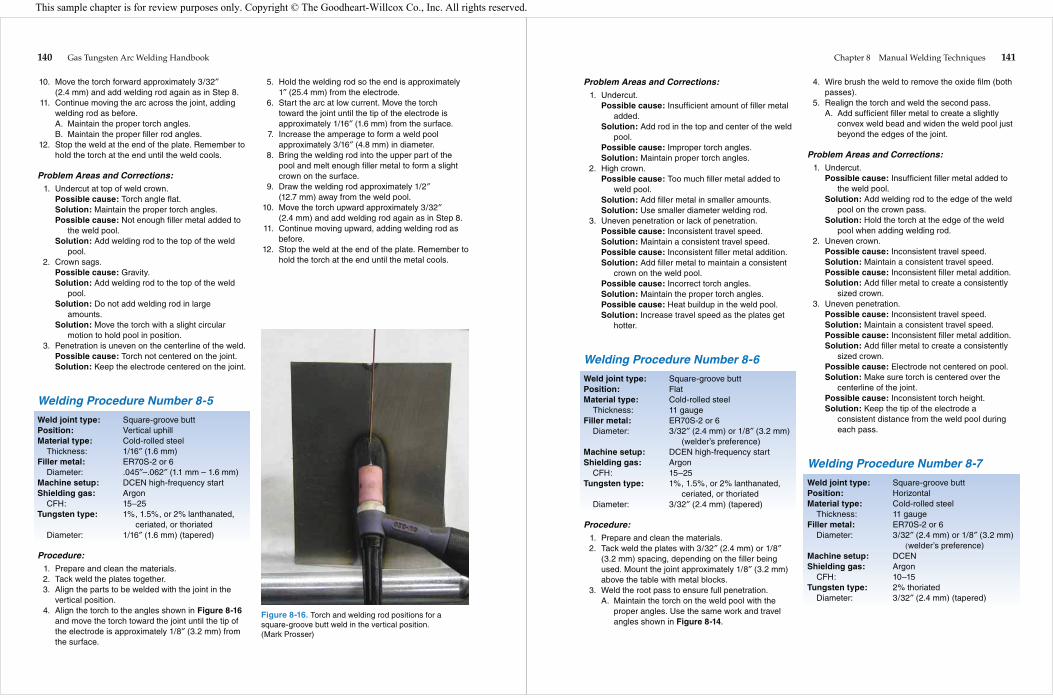
Figure 8-16. Torch and welding rod positions for a square-groove butt weld in the vertical position. (Mark Prosser)
Chapter 8 Manual Welding Techniques 141
Problem Areas and Corrections: 1. Undercut.
Possible cause: Insufficient amount of filler metal added.
Solution: Add rod in the top and center of the weld pool.
Possible cause: Improper torch angles.Solution: Maintain proper torch angles.
2. High crown.Possible cause: Too much filler metal added to
weld pool.Solution: Add filler metal in smaller amounts.Solution: Use smaller diameter welding rod.
3. Uneven penetration or lack of penetration.Possible cause: Inconsistent travel speed.Solution: Maintain a consistent travel speed.Possible cause: Inconsistent filler metal addition.Solution: Add filler metal to maintain a consistent
crown on the weld pool.Possible cause: Incorrect torch angles.Solution: Maintain the proper torch angles.Possible cause: Heat buildup in the weld pool.Solution: Increase travel speed as the plates get
hotter.
Welding Procedure Number 8-6
Weld joint type: Square-groove buttPosition: FlatMaterial type: Cold-rolled steel
Thickness: 11 gaugeFiller metal: ER70S-2 or 6
Diameter: 3/32″ (2.4 mm) or 1/8″ (3.2 mm) (welder’s preference)
Machine setup: DCEN high-frequency startShielding gas: Argon
CFH: 15–25Tungsten type: 1%, 1.5%, or 2% lanthanated,
ceriated, or thoriatedDiameter: 3/32″ (2.4 mm) (tapered)
Procedure: 1. Prepare and clean the materials. 2. Tack weld the plates with 3/32″ (2.4 mm) or 1/8″
(3.2 mm) spacing, depending on the filler being used. Mount the joint approximately 1/8″ (3.2 mm) above the table with metal blocks.
3. Weld the root pass to ensure full penetration.A. Maintain the torch on the weld pool with the
proper angles. Use the same work and travel angles shown in Figure 8-14.
4. Wire brush the weld to remove the oxide film (both passes).
5. Realign the torch and weld the second pass.A. Add sufficient filler metal to create a slightly
convex weld bead and widen the weld pool just beyond the edges of the joint.
Problem Areas and Corrections: 1. Undercut.
Possible cause: Insufficient filler metal added to the weld pool.
Solution: Add welding rod to the edge of the weld pool on the crown pass.
Solution: Hold the torch at the edge of the weld pool when adding welding rod.
2. Uneven crown.Possible cause: Inconsistent travel speed.Solution: Maintain a consistent travel speed.Possible cause: Inconsistent filler metal addition.Solution: Add filler metal to create a consistently
sized crown. 3. Uneven penetration.
Possible cause: Inconsistent travel speed.Solution: Maintain a consistent travel speed.Possible cause: Inconsistent filler metal addition.Solution: Add filler metal to create a consistently
sized crown.Possible cause: Electrode not centered on pool.Solution: Make sure torch is centered over the
centerline of the joint.Possible cause: Inconsistent torch height.Solution: Keep the tip of the electrode a
consistent distance from the weld pool during each pass.
Welding Procedure Number 8-7
Weld joint type: Square-groove buttPosition: HorizontalMaterial type: Cold-rolled steel
Thickness: 11 gaugeFiller metal: ER70S-2 or 6
Diameter: 3/32″ (2.4 mm) or 1/8″ (3.2 mm) (welder’s preference)
Machine setup: DCENShielding gas: Argon
CFH: 10–15Tungsten type: 2% thoriated
Diameter: 3/32″ (2.4 mm) (tapered)
This sample chapter is for review purposes only. Copyright © The Goodheart-Willcox Co., Inc. All rights reserved.
142 Gas Tungsten Arc Welding Handbook
Procedure: 1. Prepare and clean the materials. 2. Tack weld the plates with 3/32″ (2.4 mm) or 1/8″
(3.2 mm) spacing, depending on the filler metal used. Mount the joint in the horizontal position.
3. Weld the root pass with 3/32″ (2.4 mm) or 1/8″ (3.2 mm) diameter welding rod.A. Add the welding rod to the upper part of the
weld pool. Use the work and travel angles shown in Figure 8-15.
4. Wire brush the weld to remove the oxide film (both passes).
5. Realign the torch and weld a second pass. Use a 3/32″ (2.4 mm) or 1/8″ (3.2 mm) diameter welding rod.A. Do not oscillate the torch. The weld should be
approximately 1/16″ (1.6 mm) wider than the groove, and the weld crown should not be over 1/16″ (1.6 mm) high.
Problem Areas and Corrections: 1. Undercut.
Possible cause: Sagging due to gravity.Solution: Add welding rod at the top of the weld
pool.Possible cause: Weld bead is excessively large.Solution: Hold the torch and welding rod at the
proper angles.Solution: Do not oscillate the torch. Keep the weld
pool small.Possible cause: Excessive amperage.Solution: Use a lower amperage range and add
filler metal more often.Possible cause: Heat buildup in the weld pool.Solution: Allow the plates to cool between passes.
2. Uneven bead width.Possible cause: Variation in the size and shape of
the weld pool.Solution: Determine the size of each pass before
starting.Solution: Determine the location of each pass
before starting.Solution: Maintain the same pass dimensions for
the full length of the joint.
Welding Procedure Number 8-8
Weld joint type: Square-groove buttPosition: Vertical uphillMaterial type: Cold-rolled steel
Thickness: 11 gaugeFiller metal: ER70S-6
Diameter: 3/32″ (2.4 mm) or 1/8″ (3.2 mm) (welder’s preference)
Machine setup: DCEN high-frequency startShielding gas: Argon
CFH: 15–25Tungsten type: 1%, 1.5%, or 2% lanthanated,
ceriated, or thoriatedDiameter: 3/32″ (2.4 mm) (tapered)
Procedure: 1. Prepare and clean the materials. 2. Tack weld the plates with 3/32″ (2.4 mm) or 1/8″
(3.2 mm) spacing depending on the filler metal used. Mount the joint in the vertical position.
3. Weld the root pass with 3/32″ (2.4 mm) or 1/8″ (3.2 mm) diameter welding rod. Use the same travel and work angles shown in Figure 8-16.A. Add the welding rod to the top of the weld pool.B. Add the welding rod directly on the pool
centerline.C. Keep the electrode centered over the molten
pool. 4. Wire brush the weld to remove the oxide film (all
passes). 5. Realign the torch and weld the second pass
using a 3/32″ (2.4 mm) or 1/8″ (3.2 mm) diameter welding rod.A. Use a slight oscillation for a wider bead.B. Add welding rod at the edge of the weld pool
and always wait for a moment before dipping the filler into the weld pool. Keep the weld pool in a fluid state.
Problem Areas and Corrections: 1. Undercut.
Possible cause: Sagging due to gravity.Solution: Add welding rod at the top of the weld
pool.Possible cause: Weld bead is excessively large.Solution: Hold the torch and welding rod at the
proper angles.Solution: Do not oscillate the torch. Keep the weld
pool small.Possible cause: Excessive amperage.Solution: Use a lower amperage range and add
filler metal more often.
Chapter 8 Manual Welding Techniques 143
Possible cause: Heat buildup in the weld pool.Solution: Allow the plates to cool between passes.
2. Crooked or uneven beads.Possible cause: Variation in the size and shape of
the weld pool.Solution: Determine the size of each pass before
starting.Solution: Determine the location of each pass
before starting.Solution: Maintain the same pass dimensions for
the full length of the joint.
Welding Procedure Number 8-9
Weld joint type: T-jointPosition: HorizontalMaterial type: Cold-rolled steel
Thickness: 1/16″ (1.6 mm)Filler metal: ER70S-2 or 6 (welder’s
preference)Diameter: .045″–.062″ (1.1 mm – 1.6 mm)
Machine setup: DCEN high-frequency startShielding gas: Argon
CFH: 15–25Tungsten type: 1%, 1.5%, or 2% lanthanated,
ceriated, or thoriatedDiameter: 1/16″ (1.6 mm) (tapered)
Procedure: 1. Prepare and clean the materials. 2. Align the plates. 3. Tack weld the two plates at approximately right
angles. 4. Weld the joint using the torch and welding rod
angles shown in Figure 8-17.A. Add the welding rod often and in small
amounts.B. The filler metal will flow evenly to both pieces
and the crown should be flat to slightly convex.C. Feed the welding rod directly into the
intersection of the joint.
Problem Areas and Corrections: 1. Concave weld crown.
Possible cause: Insufficient filler.Solution: Add welding rod more often.
2. Irregular crown height or width.Possible cause: Improper feeding of welding rod.Solution: Feed welding rod into the weld pool
often, and in small quantities.
Possible cause: Too large a welding rod size causing irregular heating of the weld pool.
Solution: Use a smaller welding rod. 3. Concave root surface or melt-through.
Possible cause: Weld pool is too hot.Solution: Use a smaller diameter welding rod and
add it often to control pool temperature.Solution: Lower the amperage setting.
Welding Procedure Number 8-10
Weld joint type: T-jointPosition: HorizontalMaterial type: Cold-rolled steel
Thickness: 11 gaugeFiller metal: ER70S-2 or 6
Diameter: 3/32″ (2.4 mm) or 1/8″ (3.2 mm) (welder’s preference)
Machine setup: DCEN high-frequency startShielding gas: Argon
CFH: 15–25Tungsten type: 1%, 1.5%, or 2% lanthanated,
ceriated, or thoriatedDiameter: 3/32″ (2.4 mm) (tapered)
Procedure: 1. Prepare and clean the materials. 2. Align the plates. 3. Tack weld the two plates at approximately right
angles. 4. Weld the root pass using the torch and welding rod
angles shown in Figure 8-17.A. Add filler metal in small amounts.B. Feed the welding rod directly into the
intersection of the joint for the root pass.
Figure 8-17. Torch and welding rod positions for welding a T-joint in the horizontal position. (Mark Prosser)
This sample chapter is for review purposes only. Copyright © The Goodheart-Willcox Co., Inc. All rights reserved.

144 Gas Tungsten Arc Welding Handbook
C. Wire brush the weld to remove the oxide film (all passes).
D. Weld the second pass. Make sure the weld pool fuses into the bottom plate and overlaps the root pass by approximately 50%. See Figure 8-18.
E. Weld the third pass. Make sure the weld pool fuses into the top plate and the second pass, creating a flat weld in the joint.
Problem Areas and Corrections: 1. Concave weld crown or improper contour.
Possible cause: Insufficient filler metal.Solution: Add welding rod more often.Possible cause: Incorrect torch angle and
improperly placed welds. 2. Leg sizes are not equal.
Possible cause: Incorrect torch angle.Solution: Reposition the torch to keep the weld
pool even.Possible cause: Too much filler metal. Weld pool
is too heavy.Solution: Add less filler metal.
3. Undercut on top weld.Possible cause: Weld pool is too hot.Solution: Add welding rod more often.Possible cause: Incorrect torch angle.Solution: Reposition the torch to keep the weld
pool even.
Welding Procedure Number 8-11
Weld joint type: T-jointPosition: Vertical uphillMaterial type: Cold-rolled steel
Thickness: 11 gaugeFiller metal: ER70S-2 or 6
Diameter: 3/32″ (2.4 mm) or 1/8″ (3.2 mm) (welder’s preference)
Machine setup: DCEN high-frequency startShielding gas: Argon
CFH: 15–25Tungsten type: 1%, 1.5%, or 2% lanthanated,
ceriated, or thoriatedDiameter: 3/32″ (2.4 mm) (tapered)
Procedure: 1. Prepare and clean the materials. 2. Align the plates. 3. Tack weld the two plates at approximately right
angles. 4. Weld the joint using the torch and welding rod
angles shown in Figure 8-19.A. Add the filler metal in small amounts.B. Feed the welding rod directly into the
intersection of the joint.C. Wire brush the joint to remove the oxide film.
3rd pass
1st pass(root)
2nd pass
Figure 8-18. The three passes used to weld a T-joint in the horizontal position. (Mark Prosser)
Figure 8-19. Torch and welding rod positions for uphill welding a T-joint in the vertical position. (Mark Prosser)
Chapter 8 Manual Welding Techniques 145
Problem Areas and Corrections: 1. Convex weld crown.
Possible cause: Too much filler metal or travel speed too slow.
Solution: Add less filler metal.Solution: Increase the travel speed.
2. Concave weld crown.Possible cause: Not enough filler metal or travel
speed too high.Solution: Add more filler metal.Solution: Decrease the travel speed.
3. Leg sizes are not equal.Possible cause: Incorrect torch angles.Solution: Reposition the torch to keep the weld
pool even.Possible cause: Variation in the size of the weld
pool.Solution: Maintain a consistent travel speed and
feed the welding rod as needed to keep the weld pool size consistent.
4. Undercut.Possible cause: Improper torch work angle.Solution: Maintain the proper torch angles.Possible cause: Uneven weld pool.Solution: Add welding rod to the center of the pool.
Reading the Weld PoolThe ability to read a weld pool is a very important
skill for welders, particularly in GTAW because the weld pool is relatively small. This skill develops with practice and an increased understanding of the vari-ables that affect the weld. By reading the weld pool, a welder can tell when the travel speed is too fast or too slow and when torch angles are incorrect. The weld pool reveals discontinuities as they happen. Reading the weld pool enables the welder to make “on-the-fly” adjustments to ensure a quality weld.
Groove Weld Defects and Corrective ActionsCommon groove weld defects may be noticed during the welding operation or later during the inspection of the
completed weld. These defects are listed and illustrated with suggestions for corrective actions.
Square groove V-groove
Lack of (incomplete) penetration. A weld that does not properly penetrate into the weld joint.How to correct:• Open groove angle.• Decrease root face.• Increase root opening.• Increase amperage.• Decrease arc length.• Decrease travel speed.• Decrease torch angle.
Lack of fusion. Fusion did not occur between the weld metal and fusion faces or adjoining weld beads.How to correct:• Clean weld joint before welding.• Remove oxides from previous welds.• Open groove angle.• Decrease root face.• Increase root opening.• Increase amperage.• Decrease arc length.• Decrease travel speed.• Decrease torch angle.
Square groove V-groove
This sample chapter is for review purposes only. Copyright © The Goodheart-Willcox Co., Inc. All rights reserved.

146 Gas Tungsten Arc Welding Handbook
Overlap. Weld metal that has flowed over the edge of the joint and improperly fused with the base metal.How to correct:• Clean edge of weld joint.• Remove oxides from previous welds.• Reduce size of bead.• Increase travel speed.
Undercut. Lack of filler metal at the toe of the weld metal.How to correct:• Decrease travel speed.• Increase dwell time at edge of joint on
weave beads.• Decrease arc length.• Decrease amperage.• Decrease torch angle.
Concave weld. A concave weld occurs when insufficient metal is added to fill the joint above the groove edges.How to correct:• Add additional filler metal on the fill
passes.• Use stringer beads on crown pass.
Convex crown. A weld that is peaked in the center.How to correct:• Use less filler metal on the crown bead.
Chapter 8 Manual Welding Techniques 147
Craters. Formed at the end of a weld bead due to a lack of weld metal fill or weld shrinkage.How to correct:• Do not stop welding at end of joint (use
tabs).• Fill craters to the proper crown height and
reduce amperage slowly.
Cracks. Caused by cooling stresses in the weld and/or base metal.How to correct:• Use wire with lower tensile strength or
different chemistry.• Increase joint preheat to slow the weld
cooling rate.• Allow joint to expand and contract during
heating and cooling. Increase size of the weld.
Porosity. Caused by entrapped gas that did not have enough time to rise through the melt to the surface.How to correct:• Remove all heavy rust, paint, oil, or scale
on joint before welding.• Remove oxide film from previous passes
or layers of weld.• Protect welding area from wind.• Remove all grease and oil from the filler
metal. Handle filler metal with clean gloves.• Check gas supply for flow rate, possible
contamination, loose connections, dirty torch nozzle.
Linear porosity. Forms in a line along the root of the weld at the center of the joint where penetration is very shallow.How to correct:• Make sure root faces are clean.• Increase current.• Decrease arc length.• Increase amperage.• Decrease travel speed.
This sample chapter is for review purposes only. Copyright © The Goodheart-Willcox Co., Inc. All rights reserved.

148 Gas Tungsten Arc Welding Handbook
Melt-through. Occurs at a gap in the weld joint or place where metal is thin.How to correct:• Decrease current.• Increase arc length.• Increase travel speed.• Decrease root opening.
Concave root surface. The root of the weld penetration does not extend below the lower edges of the joint.How to correct: • Decrease travel speed.• Decrease amperage.• Decrease arc length.• Increase filler wire deposition.
Icicles. Weld penetration beyond the joint root is uneven.How to correct:• Move the torch throughout the weld length
in a consistent pattern.• Add filler metal as required to maintain an
even penetration.
Chapter 8 Manual Welding Techniques 149
Fillet Weld Defects and Corrective ActionsCommon fillet weld defects may be noticed during the welding operation or later during the inspection of
the completed weld. These defects are listed and illustrated with suggestions for corrective actions.
Lack of penetration. Insufficient weld metal penetration into the joint intersection.How to correct:• Maintain slight forward torch angle.• Increase amperage.• Decrease arc length.• Decrease size of weld deposit.• Use stringer beads• Do not make weave beads on root passes.
Lack of fusion. Occurs in multiple-pass welds where layers do not fuse.How to correct:• Remove oxides and scale from previous
weld passes.• Increase amperage.• Decrease arc length.• Decrease travel speed.
Overlap. Occurs in horizontal, multiple-pass fillet welds when too much weld is placed on the bottom layer.How to correct:• Remove oxides and scale from weld area.• Reduce the size of the weld pass.• Increase travel speed.
Undercut. Occurs at the top of the weld bead in horizontal fillet welds.How to correct:• Make a smaller weld.• Make a multiple-pass weld.• Decrease amperage.• Decrease arc length.
This sample chapter is for review purposes only. Copyright © The Goodheart-Willcox Co., Inc. All rights reserved.
150 Gas Tungsten Arc Welding Handbook
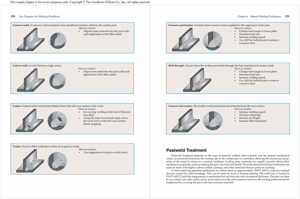
Concave weld. A concave weld is formed when insufficient metal is added to the molten pool.How to correct:• Deposit more material into the pool with
each application of the filler metal.
Convex weld. A weld that has a high crown.How to correct:• Deposit less metal into the pool with each
application of the filler metal.
Craters. Formed when weld metal shrinks below the full cross section of the weld.How to correct:• Do not stop welding at the end of the joint
(use tabs).• Using the same travel torch angle, move
the torch back on the full cross section before stopping.
Cracks. Occur in fillet welds just as they do in groove welds.How to correct:• Use suggestions for groove weld cracks.
Chapter 8 Manual Welding Techniques 151
Postweld TreatmentPostweld treatment depends on the type of material welded, joint restraint, and the desired mechanical
values. In postweld treatment, the cooling rate of the welded part is controlled, allowing the mechanical prop-erties of the metal to return to a normal condition. Cooling some materials too rapidly severely affects their mechanical properties, such as making the part very hard and brittle. Preweld and postweld heat treatments are used on steels with higher carbon content, castings, and other materials that are prone to cracking.
A stress-relieving operation performed on carbon steels at approximately 1150°F (621°C) removes residual stresses caused by weld shrinkage. This can be done by local or furnace heating. The weld area is heated to 1150°F (621°C) and this temperature is maintained for one hour per inch of material thickness. The part can then be air-cooled. Low-alloy steels can be stress-relieved in the same manner; however, the cooling period should be lengthened by covering the part with heat-resistant materials.
Excessive penetration. Formed when excessive heat is applied to the upper part of the joint.How to correct:• Change torch angle to lower plate.• Decrease bead size.• Increase welding speed.• Use chill bar behind joint to remove
excessive heat.
Melt-through. Occurs when the molten pool melts through the base material and creates a hole.How to correct:• Change torch angle to lower plate.• Decrease bead size.• Increase welding speed.• Use chill bar behind joint to remove
excessive heat.
Concave root surface. The molten weld penetration has retracted from the root surface.How to correct:• Increase welding speed.• Decrease amperage.• Increase arc length.• Increase filler metal feed.
This sample chapter is for review purposes only. Copyright © The Goodheart-Willcox Co., Inc. All rights reserved.

152 Gas Tungsten Arc Welding Handbook
Types of steel include carbon steels, low-alloy steels, heat-treated steels, and tool steels. Carbon steels are classified as low-, medium-, and high-carbon steels. Alloying elements in low-alloy steels include chromium, molybdenum, nickel, vanadium, and manganese. Heat treatments include quenching, tempering, and annealing. Tool steels are steels with a combination of high carbon and alloy content.
Common steel forms include hot-rolled steel, cold-rolled steel, castings, and forgings. Steels are manufactured to specifications developed by various organizations, including ASTM International.
Filler metals must be selected to produce the desired mechanical properties in the weldment after any required welding or heat treatment. When selecting a steel filler metal, the type of steel to be welded and the possibility of excessive porosity within the completed weld should be considered.
Joint preparation considerations include removing oxide film from edges prepared by thermal cutting processes, providing weld backing where needed, and preheating. Quenched and tempered steel requires preheat and interpass temperature control to retain the original mechanical properties of the metal.
Two torch angles that affect how the weld bead is placed into the weld joint are the work angle and travel angle. Work angles usually split the weld pool evenly between the two pieces of base metal. A good travel angle allows the welder to see the weld pool.
Stringer beads, or stringer passes, are welds made without oscillation of the torch. Weave beads are welds made with torch oscillation.
Thoriated, lanthanated, ceriated, zirconiated, and pure tungsten electrodes can be used for welding steel. Lanthanated electrodes work well for either ac or dc current and have good current-carrying capacities. Higher welding amperages require larger electrodes. An electrode that is sharpened to a point with a slight flattened tip is recommended for welding steel.
Pure argon gas can be used when welding metal up to 1/8″ (3.2 mm) thick. For increasing thicknesses, helium should be added to the shielding gas.
Manual GTAW requires a great deal of skill to perform correctly. The ability to read a weld pool must be developed so that the welder can make the appropriate adjustments to ensure a quality weld.
Write your answers on a separate sheet of paper. Do not write in this book.
1. What are the three classifications of carbon steel? 2. Medium-carbon steel has a content of _____
carbon. 3. List three alloying elements commonly used to
make low-alloy steels. 4. What is heat treating? 5. The oxide film on the surface of hot-rolled steel
is _____ in color. 6. What color is the surface of castings that have
been sandblasted? 7. Why should stainless steel filler metals not be
used for welds in service over 1000°F (538°C)? 8. List the three finishes available on steel filler
metals. 9. Why must the oxide scale be removed from the
edges of thermally cut joints before use? 10. What two types of backing are used when
welding 100% penetration steel welds? 11. Why is backing used for 100% penetration steel
welds? 12. When are carbon steels less than 1″ (25.4 mm)
thick and with less than .30% carbon preheated? 13. What causes low-alloy steels to have hard heat-
affected zones after welding? 14. What is the main reason for maintaining a good
travel angle? 15. The welding rod to be added to the molten pool
is held at what angle? 16. Tool steels should be welded with small _____
beads to reduce the amount of heat input and expansion of the base material.
17. At what approximate temperature can postweld stress relief of carbon steel weldments be done?
18. Welds made without any side-to-side movement of the torch are called _____ beads.
19. Welds made with side-to-side movement of the torch are called _____ beads.
20. When steel is being welded, a small white dot may form on the top of the molten metal. What is this material?
Summary Review Questions
This sample chapter is for review purposes only. Copyright © The Goodheart-Willcox Co., Inc. All rights reserved.

![Martensite Transformation In Sandvik Nanoflex · influence the martensite transformation [5]. Later on, the martensite fraction will be investigated that is why the martensite is](https://img.dokumen.tips/doc/110x75/5f10b9bc7e708231d44a845d/martensite-transformation-in-sandvik-influence-the-martensite-transformation-5.jpg)