Embed Size (px)
Citation preview

1
Quasi-static tests on a two-story CLT building 1
Filipe T. Matosa, Jorge M. Brancob, Patrício Rochac, Thomas Demschnerd and Paulo B. 2
Lourençoe 3
4 aPhD candidate, ISISE University of Minho, Guimarães, Portugal, [email protected] 5
bAssistant Professor, ISISE University of Minho, Guimarães, Portugal, [email protected] 6
cAssistant Professor, Polytechnic Institute of Viana do Castelo, Viana do Castelo, Portugal, 7
dR&D Manager, Building Solutions, Stora Enso, Ybbs, Austria, [email protected] 9
eFull Professor, ISISE University of Minho, Guimarães, Portugal, [email protected] 10
11 Abstract: A two-story full-scale CLT building of 4.5 m x 9.1 m in plan, with a height of 5.04 12
m, was tested under quasi-static monotonic and cyclic loading for platform-type construction. 13
The main objectives were to evaluate the global response of the structure, the performance of 14
the shear walls, the behaviour of the connectors (hold-downs and angle brackets) and the 15
frequency response of the structure during the tests. Lateral loads were applied on the storeys 16
inducing torsion to the building. Loading procedure, number and disposition of connectors 17
varied between tests. However, it is important to note that, in order to avoid a possible overlap 18
of effects, the metal connectors hold-downs and angle-brackets only have been placed in CLT 19
shear walls in each loading direction. In terms of performance, longitudinal direction presented 20
a stiffer behaviour when compared to the transverse, where it was possible to verify greater 21
sliding in the longitudinal direction and global rocking in the transverse direction. The results 22
of this experimental campaign will be used for further analytical and numerical analyses, in 23
order to help to implement more detailed seismic analysis, namely pushover, of CLT 24
constructions. 25
Keywords: Cross Laminated Timber; Pushover analysis; Shear walls; Full-scale tests. 26

2
1. Introduction 27
In the search for new solutions based on wood derivatives and with the goal of taking the 28
construction of wood to another level, Cross Laminated Timber (CLT), a competitive 29
replacement for traditional structural materials such as steel, concrete and masonry, was 30
created. It is a multi-layered shell product designed in Switzerland, in the early 1990s. The 31
panels are prefabricated and have many advantages for both wall and floors. Being a relatively 32
recent material, it is completely omitted on current European regulation EC5 [1]. On the other 33
hand, there are already CLT handbooks for the Canadian [2] and US [3] markets [4]. In the last 34
few years, full-scale tests on CLT buildings have been used to assess the performance of these 35
structures for seismic regions [5] with the purpose of analyzing the global behavior of the 36
structure after the tests were performed on individual elements: slabs and, in particular, walls. 37
Nevertheless, it is also pertinent to evaluate the response of the connections materialized by 38
metal devices like angle brackets and hold-downs based on cyclic tests. 39
Among the tests performed on a shaking table, it is important to point out the SOFIE project, 40
in which a three-story building, with 7 m x 7 m in plan and 10 m of total height, including the 41
roof, was tested with three different configurations (variation of openings). The building was 42
subjected to a series of 26 earthquakes, including the 1995 great Hanshin-Awaji earthquake (in 43
Kobe), at the NIED Laboratory, in Tsukuba, in July 2006. The results showed that the building 44
resisted to 15 destructive earthquakes without any serious damage and no significant torsion 45
was recorded [6]. 46
Another high building with seven stories was tested, in 2007, in the shaking table of the E-47
Defense laboratory in Miki, Japan. The building with 13.5 m x 7.5 m and a total height of 23.5 48
m, was submitted to the Hanshin-Awaji earthquake in Kobe, the Italian earthquake of Nocera 49
Umbra and the Kashiwazaki of the Japanese west coast. The walls of the building had 142 mm 50
on the 1st and 2nd storeys, 125 mm on the 3rd and 4th and 85 mm in the others, including the 51

3
roof. All the floors were 142 mm thick. The tests performed provided excellent results, as the 52
building behaved very well on large-scale earthquakes, with very low structural damage. 53
However, relatively high floor accelerations (maximum acceleration of 3.8 g) were recorded 54
[7]. 55
Two single-stories CLT models were tested in 2006, at the Dynamic Testing Laboratory of the 56
Institute of Earthquake Engineering and Engineering Seismology at the Ss. Cyril and 57
Methodius University, Skopje, Macedonia, using different earthquake records with PGA (Peak 58
ground acceleration) of 0.6 g. As expected, no major damage was documented [8]. 59
More recently, another CLT full-scale building was tested on the shaking table of the National 60
Laboratory for Civil Engineering (LNEC), in Portugal. In the scope of the SERIES project 61
aimed to evaluate multi-stories timber buildings, researchers from Graz University, National 62
Laboratory of Civil Engineering (LNEC), University of Trento and University of Minho, tested 63
a three-story CLT building with 5.17 m x 6.79 m in plan and 7.74 m of total height, including 64
the roof (with 5.36m at the second floor). In terms of CLT components, the walls were of 100 65
mm (3-layers) panels, the floors had 150 mm (5-layers) and the roof 99 mm (3-layers). The 66
steel connections used were angle brackets (AE116 Simpson Strong-Tie) and hold-downs 67
(HTT22 Simpson Strong-Tie) with the corresponding nails and screws. The building was 68
subjected to 32 seismic tests, in which the maximum ground acceleration was 0.5 g. At the end 69
of these tests, the building presented minor damages (located in some connections and walls) 70
with a decrease of the fundamental frequency from 3.98 Hz to 3.75 Hz [9]. 71
Popovski and Gavric [10, 11] used a different approach, based on quasi-static tests, on a CLT 72
building with 6.0 m x 4.8 m in plan and a height of 4.8 m. Most of the connections used were 73
angle brackets (BMF 116x48x3x116) and hold-downs (HTT4) but their number and location 74
varied on each test performed. The specimen was tested under monotonic and cyclic lateral 75
loading, in five different tests. All the tests showed that the main failure mechanisms were the 76

4
nails in the brackets at the bottom of the 1st floor story, as a consequence of sliding and rocking 77
(uplift) deformations of the walls. Before the tests, the building registered a 13.5 Hz (E-W) and 78
11 Hz (N-S) fundamental frequency. After all the tests, the values decreased to 10.13 Hz and 79
7.63 Hz, respectively. 80
Two other CLT buildings were analyzed with a different application of CLT panels. In plan 81
and height, both buildings presented 6.0 m x 4.0 m with 5.82 m of height, where the only 82
difference was the CLT panels around the openings. While in one building the openings were 83
cut directly on the CLT panels, in the other the openings were materialized trough segments. It 84
is also important to note that buildings only featured hydraulic jacks on the 2nd floor. The results 85
presented a greater stiffness for the structure without segmentation of the panels, where it was 86
possible to see cracks at the corners of the openings. On the other hand, with segmented walls, 87
the structure presented a high deformation caused by the rotation of each wall panel [12]. 88
Based on these results, it is established that the resistance to lateral loads is mostly related to 89
the behavior of the connections in the shear walls, where it showed high impact on flexibility 90
and therefore greater stiffness, strength and ductility. Accordingly, several configurations of 91
the panels were studied in order to evaluate the response of the panel. In the SOFIE project, 4 92
different configurations of walls were studied under quasi-static loading, where the influence 93
of the metal connectors (in contact with the foundation and CLT panels), openings and the 94
vertical loads were taken into account. The results showed that connectors have a great 95
influence on the structural response, where ductility and dissipated energy is guaranteed by the 96
metal connectors. Regarding the failure mode, damage was mainly located on metal 97
connectors, where the configuration with door opening showed a local failure of wood in 98
compression [13]. 99
Another study analyzed the influence of openings studied, two different configurations: the 100
opening of a window and door (41% of the entire panel). The results obtained showed a 101

5
significant reduction of the shear stiffness, but at the level of the load capacity, did not obtain 102
much difference [14]. 103
Similarly, with different walls ratio, a series of 12 CLT wall configurations were tested at 104
Forintek in Vancouver. The results showed that the CLT walls containing angle brackets and 105
hold-downs at each end of the wall, presented an improved performance under lateral loads. 106
On the other hand, the use of diagonal screws to connect CLT floors and CLT walls can reduce 107
the wall ductility [15]. In this context, additional research in this field has been carried out, 108
aiming to increase the knowledge of the real behavior of the shear walls [16-18]. 109
Finally, with focus on the seismic performance of timber structures, two state-of-the-art 110
reviews were performed. One with the purpose of discussing displacement-based seismic 111
design and their applications to timber buildings [19] and, on the other hand, only for CLT 112
structures, the discussion was conducted mainly for experimental tests, numerical models, q-113
behavior factor and seismic design [20]. Given the facts mentioned, even with the research 114
carried out, the regulations still do not provide a reliable method of seismic design, so there is 115
still a need for adjustments between reality and design. 116
In this way, an experimental program based on quasi-static tests was planned at the University 117
of Minho, Portugal, using a 2-story building, aiming the analysis of the 3-D system 118
performance when subjected to lateral loads. The main variables for the experimental program 119
were the analysis of lateral resistance and deformability capacity of the structure, frequency 120
response and the performance of connectors (mainly AE116 and HTT22 from Simpson Strong-121
tie). The building was designed to obtain a non-symmetric response, with a clear distinction 122
between the longitudinal (stiffer) direction and the transverse one and assuming that the center 123
of mass had to be different from the center of stiffness. However, particularly in this 124
experimental campaign, it was assumed that the metal connectors would be placed only in the 125
CLT shear walls in each loading direction. The simplification was carried out looking at the 126

6
numerical prediction of the experimental tests in a finite element model, aiming a 127
representation with greater accuracy of the in-plane behavior of the metal connectors. In fact, 128
the out-of-plane connectors have low resistance values, and therefore, can be considered as a 129
safety factor in the seismic design. Nevertheless, it is important to note that due to the technical 130
limitations of the hydraulic jacks, the loading and displacement were not sufficient to reach 131
failure of the building. Apart from these, only a cyclic test was performed, where the 132
reservation of all instrumentation and space were the main reasons. The following sections 133
present and discuss the preparation works, the tests performed and the results obtained. 134
2. Experimental Program 135
2.1. Building description 136
The building had a plan of 4.5 m x 9.1 m, with two floors, with a total height of 5.04 m. Several 137
partition walls and openings were included (a staircase on the 1st floor and on the external 138
walls), with the purpose of creating an asymmetric structure prone to torsion. The CLT panels, 139
were produced by Stora Enso Wood Products Ltd. These panels were made of spruce, with an 140
approximate density of 470 kg/m3. In terms of thickness, the CLT panels for the walls had 100 141
mm (5-layers of 20 mm) and the floors’ CLT panels had 120 mm (3-layers with 40 mm). 142
Several metal connectors were installed on the structure, mainly the angle bracket (AE116 - 143
shear resistance) and the hold-down (HTT22 - uplift resistance). However, as they play an 144
important role in final results and to avoid a possible overlapping of effects, the connectors 145
were applied only to the shear walls where the test were performed. A panoramic image and 146
plans of the building, with the location of the main connectors inserted in the tests are presented 147
in Figure 1. 148
7
Figure 1. Panoramic image (a) and building plans, with location of main connectors in the 149
tests under longitudinal (a) and transversal (b) direction. (dimensions in mm). 150
The connections between the CLT wall panels were connected with LVL (laminated veneer 151
lumber) spline joints, with the introduction of screws to ensure the continuity of the wall. The 152
same connection method was used on floors. Regarding the openings in the walls, several 153
windows and doors were included, as depicted in Figure 2. However, knowing that the 154
openings can result in structural disorders, the percentage of openings in each façade is shown 155
in Figure 2. 156
(a)
(b) (c)
8
(a) (b)
(c) (d)
Figure 2. Building facades (dimensions in mm): (a) façade A-A’; (b) façade C-C’; (c) façade 157
B-B’; (d) façade D-D’; (e) spline joint. (note that the plotted percentage values concern the 158
relative area of the openings within each façade). 159
In terms of vertical loads, for representation of a real building, in addition to own weight, the 160
remaining dead loads and the live-loads [21] (combinations of the seismic action of Eurocode 161
8 [22]) were placed over the building as additional masses, by distributing drums of water over 162
the floors. A total of 2 kN/m2 and a 1.7 kN/m2 were applied for the first and second floors, 163
respectively. 164
2.2. Setup and Instrumentation 165
The test setup was based on the need to have two lateral load additions in both directions of the 166
CLT building, one in each floor. Thus, in order to achieve accurate experimental results, the 167

9
main concerns of the test setup were: i) to have a rigid steel base to ensure an adequate fixation 168
of the building to the reaction floor of the lab, including the fixation of the CLT panels of the 169
first floor to the base with angle-brackets (AE116) and hold-downs (HTT22), as discussed 170
above (see Figure 3a); ii) steel structure to place and fix two hydraulic jacks responsible for 171
applying the lateral loads in both axes of the building (see Figure 3b); the hydraulic jacks, 172
placed in the middle of the façades, included one hinge in each extremity, to avoid other 173
deformations and stresses (see Figure 3c); iii) steel plate to ensure that the load applied by the 174
hydraulic jacks on the CLT floors is distributed (see Figure 3d). 175
176
Figure 3. Setup used in the tests: (a) Steel base structure; (b) Steel structure to fix the 177
hydraulic jacks and (c) respective hinges; (d) Steel plate placed on the floors. 178
The instrumentation system included 12 accelerometers, 4 on each level, in order to determine 179
the natural frequencies of the CLT building. On the ground floor, the accelerometers were 180
placed in each corner of the building, while, on the 1st and 2nd floor they were located only in 181
two corners, at the intersection of facades A-A’ and D-D’ (see Figure 2) and at the intersection 182
of facades B-B’ and C-C’ (see Figure 2). This information was crucial to analyze the behavior 183
of the structure and to recognize if the damage in the building was induced by the tests 184
performed. For the measurement of the displacement during each test, 24 LVDTs (Linear 185
Variable Differential Transformer) were placed in demarcated positions, ensuring that not only 186

10
the global deformation of the building, in each direction, was measured but also that the in-187
plane deformation, rotation of the floors, uplift of the walls panels and sliding were accurately 188
registered. Figure 4 shows the location of: LVDTs; hydraulic jacks; and accelerometers, 189
applied at different levels of the building. 190
(a) (b)
Figure 4. Instrumentation used in the tests under longitudinal (a) and transverse (b) direction. 191
2.3. Frequencies estimation and definition of connectors 192
Connections play an important role in the performance of CLT buildings and this case is no 193
exception. The connections between the different CLT panels are crucial to ensure an adequate 194
overall behavior of the system, keeping the different structural elements connected, while the 195
local behavior of joints is fundamental to assure the deformability, ductility, and energy 196

11
dissipation capacities needed. The connections used represented the common techniques used 197
in practice, based on the use of angle brackets as shear connectors, hold-downs taking the uplift 198
forces (tension) and adding screws to increase the stiffness of the connections. The metal 199
connectors used, angle brackets and hold-downs, were supplied by Simpson Strong-tie, while 200
the screws were from Rothoblaas (see Figure 5). To ensure a perfect distribution of the forces 201
introduced by the hydraulic jacks at the floors level, steel plates, screwed to the CLT panels, 202
were placed in both floors. Table 1 and Table 2 summarizes the different types of connections 203
used and their locations. 204
HTT22 AE116 NP20/120/240 M12 & M16 CNA4.0×60
HBS6.0×80 & HBS6.0×100 VGZ9.0×240
EVO8.0×60 HBS8.0×220
Figure 5. Connectors used in the CLT building. 205
Table 1. Main connectors used in the CLT building. 206
Location Type Reference Description
Ground floor
[CLT-to-Steel]
Angle bracket AE116 14 × CNA4.0×60 (A)
2 × M12 (B)
Hold-down HTT22 14 × CNA4.0×60 (A)
1 × M16 (B)
1st floor
[CLT-to-CLT]
Angle bracket AE116 14 × CNA4.0×60 (A)
7 × CNA4.0×60 (B)
Hold-down HTT22 14 × CNA4.0×60 (A)
1 × M16 (B)
Perforated
plate NP20/120/240 14 × CNA4.0×60 (staircase)

12
M12 - Threaded road ∅12 (8.8 Grade); M16 - Threaded road ∅16 (8.8 Grade)
207
Table 2. General fasteners used in the CLT building. 208
Quantity Location
EVO8.0×60 + M12 Steel plate-floors
2 × (HBS6.0×80) spaced to 150 mm Wall-to-wall (spline joints)
2 × (HBS6.0×100) spaced to 150 mm Floor-to-floor (spline joints)
HBS8.0×220 spaced to 150 mm Wall-to-wall
VGZ9.0×240 spaced to 150 mm Floor-to-wall
M12 - Threaded road ∅12 (8.8 Grade)
In the definition and design of the AE116 shear connections used in the CLT building, the 209
methodology proposed by Eurocode 8 [22] was adopted. In this method, the horizontal forces 210
are determined from the total mass of the building and the spectral acceleration of the building 211
for the respective period. Horizontal forces were applied independently in longitudinal and 212
transverse directions, where two separate analyses were carried out with the same seismic 213
demand. The total mass of the building admitted was 27 tons and, as the EC8 does not provide 214
a simplified method to define the period for CLT structures, the Rayleigh method was applied 215
with help of a finite element software RFEM [23] to the quantification of relative stiffness. 216
Periods of 0.277 seconds (frequency of 3.60 Hz) and 0.385 seconds (frequency of 2.60 Hz) 217
were obtained, for the longitudinal and transverse direction, respectively. In terms of seismic 218
demand, the response spectrum was defined by NTC 2008 [24]. The location defined was the 219
south of Italy (Calabria), with the goal of obtaining a spectrum with high seismic action. 220
Regarding the behavior factor used, a value of 2 (ductility class medium) was assumed, 221
according to working documents aimed to prepare a new version of Eurocode 8, chapter 8 [25, 222
26]. Under these circumstances, a peak ground acceleration of 0.42 g was found. Thus, as both 223
periods were in the area of constant spectral acceleration (horizontal behavior), the seismic 224
base shear force used for the design was 138 kN. On the other hand, the connectors HTT22, 225
were the main responsible for the uplift resistance. In order to improve the performance under 226

13
lateral loads [15], connectors HTT22 were introduced near all openings and at all corners of 227
the shear walls (see Figure 1b and Figure 1c). 228
2.4. Monotonic Tests 229
The quasi-static monotonic tests carried out consisted on the application of a displacement 230
under a constant rate, on each floor, respecting the ISO/FDIS 21581:2010 [27]. Two hydraulic 231
jacks were used, one in each floor, to apply the displacements under a constant rate of 232
0.08 mm/s and 0.04 mm/s on the second and first floor, respectively. Due to technical 233
limitations, namely the load capacity of the hydraulic jack installed on the second floor, the 234
criterion adopted to stop the tests was a load value of 300 kN in that hydraulic jack. Two tests 235
were performed: one for each direction, longitudinal and transverse. 236
2.5. Cyclic Test 237
The cyclic test, was also based on the loading procedure standardized by ISO/FDIS 21581:2010 238
[27], where the analysis was only in the transverse direction. Therefore, contrary to what 239
happened with the monotonic tests, the loading procedure was, here, performed by force 240
control, in which 0.90kN/s was admitted on the 1st floor and 1.80kN/s on the 2nd floor. 241
Consequently, on the cyclic test, when the need for greater displacement of the hydraulic jacks 242
occurred, the limitation was given by the maximum displacement of the 1st hydraulic floor of 243
100mm (50mm positive and 50mm negative). Concerning the values to be reached for each 244
step, this was achieved based on the ultimate displacement (lu). Due to the lack of definition 245
of this value, a final displacement equal to the total height of the building divided by fifteen 246
(H/15), according to the standard, was admitted. Since this factor is quite conservative, the 247
number of cycles of the fourth and fifth steps of the loading procedure was changed to three 248
(see Figure 6). In relation to the inserted connections, they were equal to the ones in the 249

14
monotonic test in the transverse direction, although all connections AE116 and HTT22 used 250
were removed and new ones were introduced. 251
252
Figure 6. Loading procedure defined by ISO/FDIS 21581:2010 for cyclic tests [27]. 253
3. Results and discussion 254
The main results obtained in the experimental program are described and discussed. Two 255
experiments have been performed under monotonic loading and one with cyclic loading, and 256
the results were separated in three groups: load-deformation response, dynamic analysis and 257
damages observed. 258
3.1 Load-deformation response 259
Table 3 and Figure 7 show the deformability of the building at different levels, concerning the 260
results of the measurement of displacement (LVDTs) for the center of the facades A-A’ and C-261
C’ (location of the hydraulic jacks) and the farthest point in relation to the hydraulic jacks, 262
region where greater displacements were obtained (intersection of facade B-B' and D-D'). It is 263
important to note that the monotonic tests were stopped when the criterion of the limitation for 264
the load applied by the hydraulic jack of the second floor (300 kN) was reached. Contrarily to 265
the monotonic tests, for the cyclic test, due to the greater need of displacement, the hydraulic 266
jacks of the first floor determined the stopping criterion, only having 100 mm of maximum 267
displacement (50 mm for each direction). However, due to loss of displacements in the 268
introduced hinges, the maximum displacement reached in the 1st floor was 30 mm. 269

15
Table 3. Lateral deflection (mm) measured during the tests performed 270
Test Monotonic
Longitudinal
Monotonic
Transverse
Cyclic
Transverse
Location Hydraulic jacks
1st story
Sliding 8.0 (0.32% h) 14.1 (0.56% h) 7.4 (0.30% h)
In-plan
deformation 34.5 (1.37% h) 47.4 (1.88% h) 30.0 (1.19% h)
Rocking 7.9 (0.31% h) 16.6 (0.66% h) 15.9 (0.63% h)
2nd story Sliding 0.9 (0.03% h) 2.2 (0.09% h) 2.9 (0.12% h)
In-plan
deformation 45.9 (1.82% h) 74.3 (2.95% h) 52.4 (2.08% h)
Rocking 1.6 (0.06% h) 2.7 (0.11% h) 2.3 (0.09% h)
Location intersection of facades B-B 'and D-D'
1st story
Sliding 30.4 (1.21% h) 16.5 (0.66% h) 12.7 (0.50% h)
In-plan
deformation 34.5 (1.37% h) 57.4 (2.28% h) 37.3 (1.48% h)
2nd story
Sliding 5.1 (0.20% h) 6.4 (0.25% h) 5.5 (0.22% h)
In-plan
deformation 46.6 (1.85% h) 84.4 (3.35% h) 57.8 (2.29% h)
h – Story height
(a)
(b) (c)
0
1
2
0 0.5 1 1.5 2 2.5 3 3.5 4
Sto
ry
Lateral deformability (%)
Monotonic
Longitudinal
Center
Align. B-D
0
1
2
0 0.5 1 1.5 2 2.5 3 3.5 4
Sto
ry
Lateral deformability (%)
Monotonic
Transverse
Center
Align. B-D
0
1
2
0 0.5 1 1.5 2 2.5 3 3.5 4
Sto
ry
Lateral deformability (%)
Cyclic
Transverse
Center
Align. B-D
16
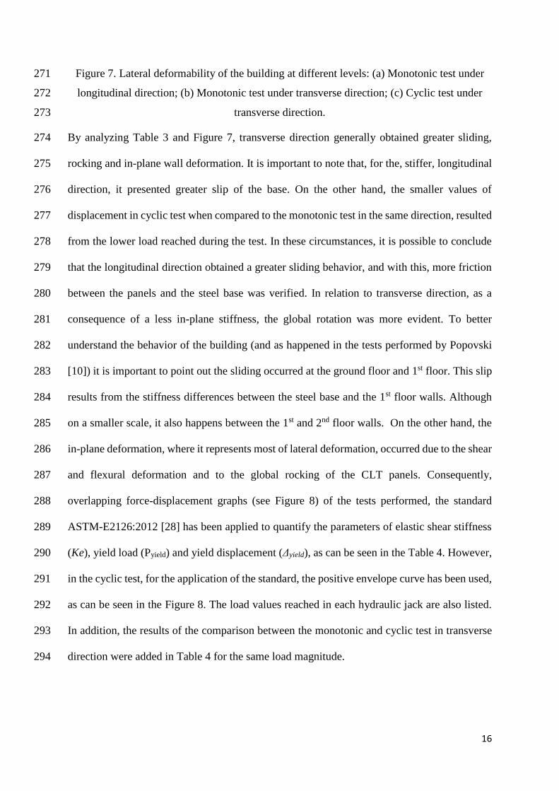
Figure 7. Lateral deformability of the building at different levels: (a) Monotonic test under 271
longitudinal direction; (b) Monotonic test under transverse direction; (c) Cyclic test under 272
transverse direction. 273
By analyzing Table 3 and Figure 7, transverse direction generally obtained greater sliding, 274
rocking and in-plane wall deformation. It is important to note that, for the, stiffer, longitudinal 275
direction, it presented greater slip of the base. On the other hand, the smaller values of 276
displacement in cyclic test when compared to the monotonic test in the same direction, resulted 277
from the lower load reached during the test. In these circumstances, it is possible to conclude 278
that the longitudinal direction obtained a greater sliding behavior, and with this, more friction 279
between the panels and the steel base was verified. In relation to transverse direction, as a 280
consequence of a less in-plane stiffness, the global rotation was more evident. To better 281
understand the behavior of the building (and as happened in the tests performed by Popovski 282
[10]) it is important to point out the sliding occurred at the ground floor and 1st floor. This slip 283
results from the stiffness differences between the steel base and the 1st floor walls. Although 284
on a smaller scale, it also happens between the 1st and 2nd floor walls. On the other hand, the 285
in-plane deformation, where it represents most of lateral deformation, occurred due to the shear 286
and flexural deformation and to the global rocking of the CLT panels. Consequently, 287
overlapping force-displacement graphs (see Figure 8) of the tests performed, the standard 288
ASTM-E2126:2012 [28] has been applied to quantify the parameters of elastic shear stiffness 289
(Ke), yield load (Pyield) and yield displacement (Δyield), as can be seen in the Table 4. However, 290
in the cyclic test, for the application of the standard, the positive envelope curve has been used, 291
as can be seen in the Figure 8. The load values reached in each hydraulic jack are also listed. 292
In addition, the results of the comparison between the monotonic and cyclic test in transverse 293
direction were added in Table 4 for the same load magnitude. 294

17
295
Figure 8. Force-displacement on top of the CLT building registered during the tests. 296
Table 4. Mechanical parameters with application of the ASTM-E2126:2012. 297
Tests Force (kN)
1st story/2nd story
Ppeak
(kN)
Δpeak
(mm)
Pyield
(kN)
Δyield
(mm)
Ke
(N/mm)
Monotonic Longitudinal 228.4/300.0 528.4 45.9 408.8 5.6 63241
Monotonic Transverse 147.7/300.0 447.7 74.3 347.5 19.2 14911
Monotonic Transverse(a) 142.2/266.8 409.0 60.1 328.3 21.4 15312
Cyclic Transverse 136.3/272.7 409.0 52.3 328.8 29.1 9910
Ppeak - Maximum load; Δpeak - Maximum displacement; Δyield - Yield displacement; Pyield
- Yield load; Ke - Elastic shear stiffness; (a) Load magnitude of the cyclic test.
By looking at Figure 8 and Table 4, one can demonstrate that the CLT building is stiffer in the 298
longitudinal direction when compared to the transverse direction, with a significant increase of 299
the load capacity of the structure in that direction. On the other hand, when analyzing the tests 300
in the transversal direction, the cyclic test presents lower values of resistance. Regarding the 301
comparison between the monotonic and cyclic test in the transverse direction with same load 302
magnitude, the results demonstrates the decrease of the resistance of the cyclic test. This 303
decrease can be considered normal given that the cyclic test is more aggressive to the structure, 304
in which there occurred a decrease in maximum displacement (around 13%), yielding 305
displacement (around 36%) and elastic shear stiffness (around 35%). However, it is important 306
to note that the value of yielding load is close. 307
-400
-300
-200
-100
0
100
200
300
400
500
600
-60 -50 -40 -30 -20 -10 0 10 20 30 40 50 60 70 80
Bas
e sh
ear
forc
e (k
N)
Displacement on top (mm)
Monotonic LongitudinalMonotonic TransverseCyclic Transverse (Envelope Curve)

18
3.2 Dynamic analysis 308
In relation to the results of the dynamic identification, Table 5 shows the natural frequencies 309
for the cases with and without additional masses and before and after each test performed. 310
Table 5. Natural frequencies obtained during the tests. 311
Test
Natural frequency (Hz)
Transverse direction (mode 1) Longitudinal direction (mode 2)
before after Δ (%) before after Δ (%)
Identification* 8.2 5.0 38.6% 19.2 12.5 34.9%
Mono. Longitudinal 5.0 4.9 2.4% 12.5 11.0 12.2%
Mono. Transverse 6.0 4.9 18.5% 6.4 5.8 9.8%
Cyclic Transverse 5.6 4.6 18.1% 5.8 4.9 15.8%
*before and after the introduction of additional masses
Analyzing the values presented in Table 5, for the direction in which the tests were performed, 312
the transverse tests obtained greater damage (reduction of 18.5% and 18.1%) when compared 313
to longitudinal test (reduction of 12.2%). In relation to the additional masses inserted in the 314
building, the natural frequency decreased on 38.6% and 34.9% for the transverse and 315
longitudinal direction, respectively. 316
3.3 Damages observed 317
The damages observed during the tests were very similar for all the tests performed, where the 318
difference was given by the level of damage imposed on the building. In this way, and as 319
expected, the damages observed during the test in the transverse direction, were more severe, 320
due to the fact that this loading direction is the one with less stiffness. On the other hand, with 321
the longitudinal direction being the stiffest, practically insignificant damages were found 322
between the walls of the 2nd floor and the 1st floor. In this context, as the building suffered 323
global rotation, the first visible damages concentrated at the base, where the hydraulic jacks 324
were located (see Figure 9). 325

19
(a) (b)
Figure 9. Rocking of the building on longitudinal (a) and transverse (b) monotonic tests. 326
In terms of in-plane walls deformation, as non-metal connectors (angle-brackets and hold-327
downs) were placed just in relation to the load application, the building suffered a significant 328
lateral translation in internal walls (see Figure 10). 329
(a) (b)
Figure 10. Translation of the internal walls on (a) longitudinal and (b) transverse tests. 330
The highest damage observed was located in the metal connectors. For the most part, the 331
connectors have been damaged as a consequence of sliding and rotation (see Figure 11a) and 332
uplift (see Figure 11b and Figure 11c). Moreover, in some cases, AE116 connectors underwent 333
a small uplift, in which the screws that connect the steel structure of the base were virtually 334
undamaged. On the other hand, because the center of the mass is different from the center of 335
stiffness, the hold-downs presented out-of-plane rotation (see Figure 11d). In addition, through 336
the monotonic tests, it was possible to observe damage (plasticization) of the metal connectors 337
20
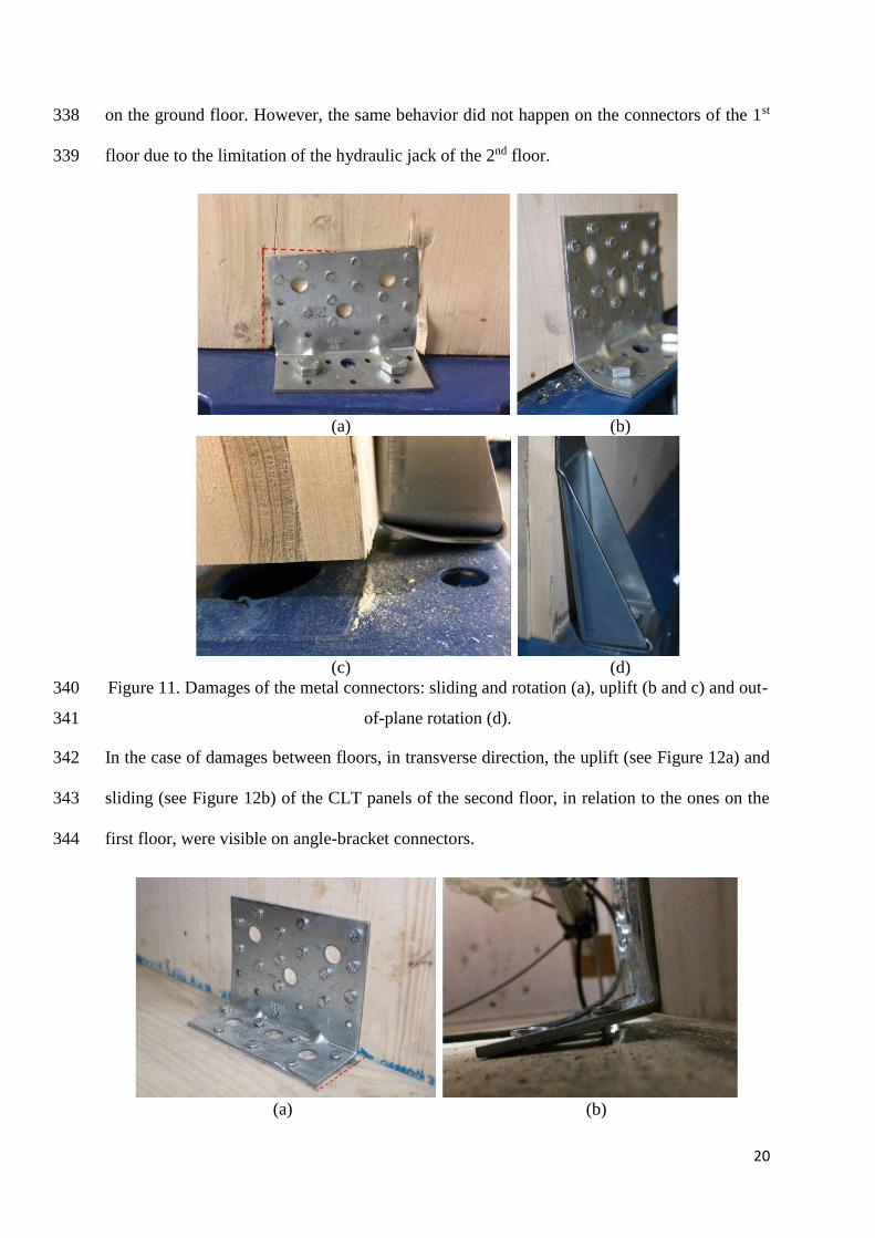
on the ground floor. However, the same behavior did not happen on the connectors of the 1st 338
floor due to the limitation of the hydraulic jack of the 2nd floor. 339
(a) (b)
(c) (d)
Figure 11. Damages of the metal connectors: sliding and rotation (a), uplift (b and c) and out-340
of-plane rotation (d). 341
In the case of damages between floors, in transverse direction, the uplift (see Figure 12a) and 342
sliding (see Figure 12b) of the CLT panels of the second floor, in relation to the ones on the 343
first floor, were visible on angle-bracket connectors. 344
(a) (b)

21
Figure 12. Sliding (a) and uplift (b) of nails in the connectors AE116. 345
Finally, as a consequence of a less in-plane stiffness of the transverse direction, in the 346
monotonic test, the lintels over the openings on the ground floor wall in the façade B-B’ (see 347
Figure 13) cracked by tension perpendicular to the grain. 348
(a) (b) (c)
Figure 13. Cracks on top left corner of the openings 1500x2000 (a and b) and 900x2000
(c) on the ground floor wall in the facade B-B' during the monotonic transverse test
4. Conclusions 349
A non-symmetric 2-storey full-scale structure with large openings was tested for platform-type 350
buildings. The performance, at global and local levels, in each loading direction, was analyzed. 351
In the longitudinal direction, since the structure is stiffer, no significant damage was registered. 352
This can be explained by the technical limitation of the hydraulic jack used in the second floor. 353
In the first monotonic test, under a lateral load in the longitudinal direction of the building, the 354
damage observed was concentrated in the metal connectors (angle-brackets and hold-downs), 355
with signs of sliding, rotation and uplift on the ground floor. In the transverse direction, with 356
short shear walls, more damages were observed. The rotation of the overall structure was 357
visible and the lintels over the larger openings cracked by tension perpendicular to the grain. 358
Finally, yet significantly, in the cyclic test in the transverse direction, the damages were very 359
similar to the monotonic test in the same direction, but in the former, more severe damages 360

22
were observed in the angle brackets on the first floor. The fundamental frequencies of the CLT 361
building were measured through dynamic identification. Measurements were done, with and 362
without additional masses, before any load tests, and always before and after each test, 363
monotonic and cyclic, performed. However, although the building's load capacity was not 364
reached in the tests performed, it was possible to verify accumulated damage to the building. 365
Under those circumstances, the prediction will be essential in the implementation of the 366
pushover method in CLT structures, where the goal is related to the application of the N2 367
method to several study cases. 368
5. Acknowledgements 369
The authors thank Stora Enso Wood Products and Simpson Strong Tie for their contribution 370
with all materials used, and to the technicians of the Structures Laboratory of the Civil 371
Engineering Department at University of Minho for the time and dedication given during this 372
experimental program. 373
References 374
[1] European Committee for Standardization (CEN), EN 1995-1:2004, Eurocode 5: Design 375
of timber structures - Part 1-1: General - Common rules and rules for buildings, CEN, 376
Brussels, 2004. 377
[2] Karacabeyli E, Douglas B, CLT Handbook: Cross-Laminated Timber. US Edition, 378
2013. 379
[3] Gagnon S, Pirvu C, CLT Handbook: Cross-Laminated Timber. Canadian Edition, 2011. 380

23
[4] Brandner R, Flatscher G, Ringhofer A, Schickhofer G, Thiel A. Cross laminated timber 381
(CLT): overview and development. European Journal of Wood and Wood Products 382
2016; 331-351. https://doi.org/10.1007/s00107-015-0999-5. 383
[5] Pei S, Van De Lindt JW, Popovski M, Berman JW, Dolan JD, Ricles JM, et al. Cross-384
Laminated Timber for Seismic Regions: Progress and Challenges for Research and 385
Implementation. Journal of Structural Engineering 2014;142(4) E2514001. 386
https://doi.org/10.1061/(ASCE)ST.1943-541X.0001192. 387
[6] Ceccotti A, Follesa M. Seismic behavior of multi-story X-Lam buildings. in: Int. 388
Workshop on Earthquake Engineering on Timber Structures; 2006. 389
[7] Ceccotti A, Sandhaas C, Okabe M, Yasumura M, Minowa C, Kawai N. SOFIE project 390
- 3D shaking table test on a seven-storey full-scale cross-laminated building. 391
Earthquake Engineering & Structural Dynamics 2013;42(13):2003–21. 392
https://doi.org/10.1002/EQE.2309. 393
[8] Dujic B, Hristovski V, Stojmanovska M, Zarnic R. Experimental Investigation of 394
Massive Wooden Wall Panel Systems Subjected to Seismic Excitation. in: Proceedings 395
of the First European Conference on Earthquake Engineering and Seismicity, Geneva, 396
Switzerland; 2006. 397
[9] Costa AC, Candeias PX, Flatscher G, Schickhofer GR. Seismic perfomance of multi-398
storey timber buildings: TUGraz building. Series Report, Lisbon, Portugal; 2013a. 399
[10] Popovski M, Gavric I. Performance of a 2-Story CLT House Subjected to Lateral 400
Loads. Journal of Structural Engineering 2016;142(4) E4015006. 401
https://doi.org/10.1061/(ASCE)ST.1943-541X.0001315. 402

24
[11] Popovski M, Gavric I, Schneider J. Performance of two-storey CLT house seubjected 403
to lateral loads. Proceedings of the 12th World Conference on Timber Engineering 404
WCTE 2014, Quebec, Canada. 2015; https://doi.org/10.13140/RG.2.1.3582.9280. 405
[12] Yasumura M, Kobayashi K, Okabe M, Miyake T, Matsumoto K, Full-Scale Tests and 406
Numerical Analysis of Low-Rise CLT Structures under Lateral Loading. Journal of 407
Structural Engineering 2015;142 E4015007. https://doi.org/10.1061/(ASCE)ST.1943-408
541X.0001348. 409
[13] Lauriola MP, Sandhaas C. Quasi-static and pseudodynamic tests on X-lam walls and 410
buildings. COST Action E29 Workshop ‘Earthquake Engineering on Timber 411
Structures’, Dept. of Civil Engineering, Faculty of Sciences and Technology, Univ. of 412
Coimbra, Portugal. 2006; pp. 119-133. 413
[14] Dujic B, Klobcar S, Zarnic R. Influence of openings on shear capacity of wooden walls. 414
Proc., 40th CIB-W18 Meeting, Ingenieurholzbau und Baukonstruktionen, Karlsruhe 415
Institute of Technology, Germany; 2007. 416
[15] Popovski M, Schneider J, Schweinsteiger M. Lateral load resistance of cross-laminated 417
wood panels. Proc., 11th World Conf. on Timber Engineering WCTE 2010, A. Ceccotti 418
and J.-W. van de Kuilen, eds., Riva del Garda, Italy; 2010. 419
[16] Seim W, Hummel J, Flatscher G, Schickhofer G. CLT Wall elements under cyclic 420
loading-Details for anchorage and connection. Proc., COST Action FP1004 Conf. on 421
the State-of-the Art in CLT Research, Univ. of Bath, North East Somerset, U.K; 2013. 422
25
[17] Gavric I, Fragiacomo M, Ceccotti A. Cyclic behavior of CLT wall systems : 423
experimental tests and analytical prediction models. ASCE Journal of Structural 424
Engineering; 1–14; 2015. 425
[18] Málaga-Chuquitaype C, Skinner J, Dowdall A, Kernohan J. Response of CLT shear 426
walls under cyclic loads. World Conference on Timber Engineering, Vienna, Austria; 427
2016. 428
[19] Cristiano L, Thomas T, Solomon T. State-of-the-art review of displacement-based 429
seismic design of timber buildings. Construction and Building Materials 2018; 430
191:481-497. https://doi.org/10.1016/j.conbuildmat.2018.09.205. 431
[20] Izzi M, Casagrande D, Bezzi S, Pasca D, Follesa M, Tomasi R. Seismic behaviour of 432
Cross-Laminated Timber structures: A state-of-the-art review. Engineering Structures 433
2018; 170:42-52. https://doi.org/10.1016/j.engstruct.2018.05.060. 434
[21] European Committee for Standardization (CEN), EN 1991-1:2002, Eurocode 1, 435
Actions on structures, Part 1-1: General actions - Densities, self-weight, imposed loads 436
for buildings, CEN, Brussels; 2002. 437
[22] European Committee for Standardization (CEN), EN 1998-1:2004, Eurocode 8, Design 438
of structures for earthquake resistance, part 1: general rules, seismic actions and rules 439
for buildings, CEN, Brussels; 2004. 440
[23] Dlubal software GmbH®. Structural Engineering Software for Analysis and Design, 441
Version 5.17.01. Germany; 2017. 442
[24] NTC 2008, Norme Tecniche per le Costruzioni. DM 14 gennaio 2008, G.U. n. 29, 4 443
febbraio, n. 30; 2008. 444

26
[25] Follesa M, Fragiacomo M, Casagrande D, Tomasi R, Piazza M, Vassallo D, et al. The 445
new version of chapter 8 of Eurocode 8. World Conference of on Timber Engineering. 446
WCTE 2016; 2016. 447
[26] Follesa M, Fragiacomo M, Casagrande D, Tomasi R, Piazza M, Vassallo D, et al. The 448
new provisions for the seismic design of timber buildings in Europe. Engineering 449
Structures. 168 736-747. https://doi.org/10.1016/j.engstruct.2018.04.090; 2018. 450
[27] ISO/FDIS 21581, Timber structures - Static and cyclic lateral load test methods for 451
shear walls; 2010. 452
[28] ASTM E2126-11, Standard Test Methods for Cyclic (Reversed) Load Test for Shear 453
Resistance of Vertical Elements of the Lateral Force Resisting Systems for Buildings; 454
2012. 455


![Magnetic quasi-static simulation [coreless liquid-cooled motor]](https://img.dokumen.tips/doc/110x75/56816864550346895ddeb859/magnetic-quasi-static-simulation-coreless-liquid-cooled-motor.jpg)