Embed Size (px)
Citation preview

9.1 Introduction
Quality control is applied to most industrial processes and is a standardand relatively easy function for paint applied in a continuous operation,for example coating of cars, domestic appliances, etc. Quality control ofthe coating of structural steel, however, encounters some unique factors.
Most paint coatings are, at least superficially, remarkably tolerant ofvariations in application conditions and procedures. However, it is gener-ally impossible to tell from the appearance of the coating whether it hasbeen applied over a suitable surface or has formed the correct polymer togive optimum performance. There are, as yet, no positive tests that can beapplied to a paint film in situ that will provide this assurance. Manyworkers are investigating electrical measurements of paint films, such asAC impedance testing, but such tests are, as yet, not fully correlated withactual long-term performance.
One problem is the manner in which coatings fail. Loss of adhesion,visible corrosion, blistering, etc., which occur within a year or two of appli-cation are obvious faults. It is in everyone’s interest to avoid such failures,particularly since adequate repair work is nearly always more expensiveand troublesome than the initial work and almost inevitably to a lowerstandard. However, less obvious failures are those where there are shortertimes than necessary between maintenance and with the requirement forextensive and expensive surface preparation.
It must be added that often there are many people in the coatings chainwho are not interested in very long-term durability. However, someauthorities faced with a likely maintenance programme that was beyondtheir resources and likely to get worse, addressed the problem some yearsago and are now reaping the rewards.
The UK Highways Agency have now greatly increased the maintenancerepainting intervals on motorway bridges. According to those responsiblefor arranging or undertaking the maintenance work, the majority of exist-ing structures are now undergoing major maintenance at intervals in
Chapter 9
Quality control of coatingoperations
© 2002 D. A. Bayliss and D. H. Deacon

Quality control of coating operations 209
excess of 20 years.1 This has been achieved by comprehensive speci-fications, testing and monitoring of paint materials, particular concern withsurface preparation and removal of water-soluble contaminants and,last but not least, independent painting inspection of the entire coatingoperation.
In the early 1980s British Petroleum adopted QA/QC procedures thatincluded full-time independent painting inspection and now consider thatthe higher standards of workmanship achieved have shown considerableeconomic benefit.2
One large chemical plant in Germany has also found that intervalsbetween maintenance can be extended considerably although they operatewith a fairly high ratio of one inspector to 15–25 painters.3
Another large manufacturer of chemicals in the United States has esti-mated that the use of professional painting inspection can, over 10 years,save $941000 for every $1000000 dollars of the original cost of painting.
As with all quality control activities, they must be carried out indepen-dently of those involved in production, i.e. the operators carrying outsurface preparation and coating application. These operators should, ofcourse, be properly supervised and carry out their work to meet the con-tract requirements. However, they may have priorities other than thoseprovided by the technical specification, not least the meeting of deadlinesand payment on the basis of the amount of work done in a given time.There is, therefore, often a genuine conflict between quality and produc-tion; something not unique to coating processes. The user has to decidewhether the additional cost of inspection, for example 5% on paintingcosts, is worthwhile. Usually there is no guarantee of performance of thecoating system in relation to the inspection, so the judgement as to its usemust be based on factors such as the experience of the user with respect toinspection carried out on previous projects; the data concerning the per-formance of coatings that have been subjected to inspection comparedwith those that have not; and the importance of the project itself.
The situation is summed up by S. T. Thompson,4 who states
. . . it depends upon four cornerstones: good specifications, qualitymaterials, qualified contractors, and effective inspection. Failure in anyof these areas, like the proverbial weak link in the chain, will result indecreased performances and increased costs – often substantial.
Generally, any inspection is preferable to none, although there are excep-tions to this; for example, where inspection reaches a level of incom-petence that leads to either unnecessary delays, possibly entailingconsiderable additional costs, or a failure to apply the correct technicalprocedures. In some cases it could be said with some truth that ‘poorinspection is worse than no inspection’. Most users who regularly specify
© 2002 D. A. Bayliss and D. H. Deacon

210 Steelwork corrosion control
inspection for their projects will be aware of these problems, but for thosewith less experience it may be difficult to decide on the benefits or, indeed,sometimes the nature of the inspection. In the following sections, thevarious aspects of inspection will be considered.
9.2 Inspection requirements
Strictly speaking, inspection is carried out to ensure that the requirementsof the coating specification are met by the contractor. Sometimes otherduties are added and this may well be advantageous, but the primeresponsibility of the inspector is clear: to ensure that the work is carriedout in accordance with the specification. Although inspection may becarried out by any group independent of those involved in production,including personnel from the user’s own organisation, it is often done byindependent firms that have been specially formed for this purpose.
Sometimes such firms are invited to prepare the coating specificationand even to provide a measure of supervision of the coating operations.This may well prove to be beneficial but does not alter the basic require-ments already described. Inspection is a quality control measure andshould not be confused with other important requirements involved incoating procedures. The coating specification is the essential basis for pro-viding a sound protective system. This is considered in Chapter 8, but itmust be said that some specifications are not of a standard likely toprovide the highest quality of coating performance. Although the inspec-tor may comment to this effect, he has no authority to alter the specifica-tion. Consequently, if his advice is not taken he may well find himself in aposition where he carries out his duties conscientiously ensuring that aninadequate specification is correctly applied which may eventually lead toa coating of poor durability. It must be appreciated that in such a situationthe fault lies with the specification, not the inspector; where inspection isto be used, the requirements should, of course, be included as part of thespecification.
The user must be quite clear in his inspection requirements and mustnot expect more than is intended. If a consultancy–management operationis required then this should be decided at the outset. No matter how com-petent the inspector may be, he cannot be expected to act as a substitutefor a sound specification, good management and proper planning. Thebasic requirements for a good inspector are considered in the next sectionand the user will be well advised to ensure that these criteria are met bythose called upon to carry out quality control work on his behalf.
The nature and importance of the requirements for quality control arebeing increasingly appreciated, so the approach used should also be con-sidered in a more critical manner.
In some ways the term ‘coating inspection’ is a misnomer because it may
© 2002 D. A. Bayliss and D. H. Deacon
Quality control of coating operations 211
imply that it is confined to an assessment of the final coating, whereas itcovers the whole coating process. The term ‘quality control’ is probablymore correct.
9.3 The approach to quality control
The aim of quality control is to ensure that coatings attain their full poten-tial of performance. Inspection is one of the steps involved but, to gain fulladvantage from it, other aspects must also be considered. The main stagesin obtaining the optimum performance from coatings can be summarisedas follows:
(i) A full consideration of the coating requirements and the selectionof a system suitable for the particular conditions.
(ii) Appraisal of the design of the structure relative to coating applica-tion and performance.
(iii) The choice of coating processes applicable to the fabrication tech-niques involved, or sometimes the choice of fabrication to suit thecoating.
(iv) Preparation of a concise unambiguous coating specification.(v) Tendering and acceptance of the requirements by the contractor.
(vi) Checking, where appropriate, on the quality of the materials speci-fied and supplied.
(vii) Inspection at all stages of the coating process, including handling,storage and erection.
For maintenance painting, as opposed to new work, there may be addi-tional requirements, as discussed in Chapter 11, e.g. a survey of the paint-work and tests to determine the feasibility of the maintenance procedures.
Clearly, inspection alone will not overcome problems arising from poordecisions in (i)–(vi) above, although in some situations the organisationresponsible for inspection may be involved in these other areas. At thevery least, such matters should be discussed so that the inspector isabsolutely clear regarding the requirements and responsibilities for hispart of the work. He cannot reasonably be expected to interpret unclear orambiguous specifications and in fact it may be inappropriate for him to doso. Any doubts or problems should be cleared up by discussions amongthe interested parties before the work begins.
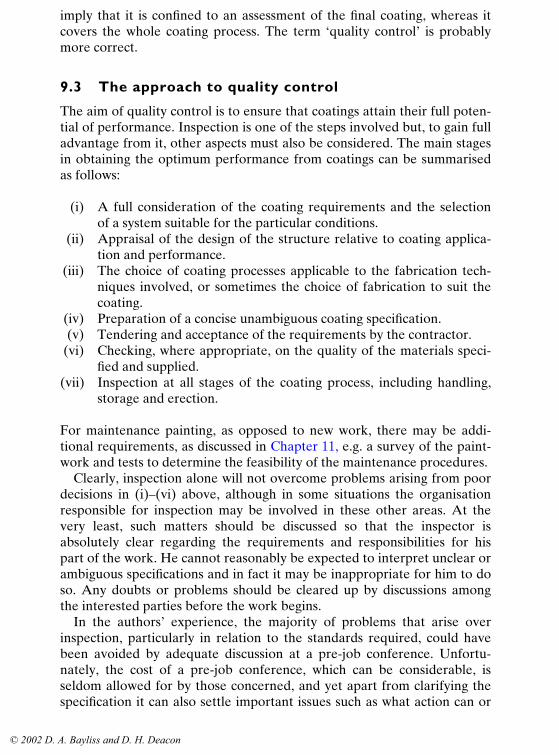
In the authors’ experience, the majority of problems that arise overinspection, particularly in relation to the standards required, could havebeen avoided by adequate discussion at a pre-job conference. Unfortu-nately, the cost of a pre-job conference, which can be considerable, isseldom allowed for by those concerned, and yet apart from clarifying thespecification it can also settle important issues such as what action can or
© 2002 D. A. Bayliss and D. H. Deacon

212 Steelwork corrosion control
cannot be taken by the inspector, what the specific safety requirementsare, and how and to whom the inspector should report problems. Prob-lems will arise that cannot always be foreseen, but there is no excuse forwork being held up while, for example, arguments take place regardingwhether the coating thickness in the specification was intended to beminimum, maximum or average.
Costs are obviously attributable to all the stages listed above and anopinion must be taken by the engineer of the amount considered reason-able for the project. For minor works, particularly where hand cleaning ofthe steelwork is to be used, limitation on cost may be necessary. However,for important projects, e.g. submarine pipelines, tank linings, bridges, etc.,no long-term advantage will accrue from carrying out any stage with lessthan fully competent personnel with suitable expertise for the roles theyundertake. Before considering inspection in detail it is worth discussingsome of the related aspects which, while not falling within the strict defini-tion of inspection as expressed earlier, nevertheless will be of benefit tothe inspection work.
Although many large organisations have specialists capable of selectingcoating systems and preparing coating specifications, others do not carrythis expertise in-house. Advice can be sought from the coatings suppliersand generally this will be of a high standard. However, it will clearly bebiased towards their own products. This may not be particularly importantwith some paint products that are made to a similar formulation and stan-dard by a range of manufacturers. It becomes more crucial, however, withspecialist coatings. Often the products from different manufacturers arenot the same, even though their descriptions may be covered by similargeneric terminology. In these cases, independent advice may be preferred.Again, by the nature of tendering, contractors will often offer a productwhich is unfamiliar to the engineer and independent assessments may beadvantageous. The engineer may then take advice from a protective coat-ings consultant or from the organisation involved with the inspection.Provided the organisation has sufficient expertise, the following maybe considered as appropriate areas for advice and discussion.
(i) Carrying out an audit of the design in relation to its susceptibility tocorrosion and the problems of coating application. Offering advice onchanges to improve the situation, taking into account cost and the overalleffects of such changes.
(ii) Advising on the selection of suitable protective systems and dis-cussing the requirements with coatings suppliers, taking into accountfuture maintenance requirements and overall costs.
(iii) Advising on the preparation of a suitable coatings specification andthe levels and requirements of inspection to be incorporated.
(iv) Discussions and advice on the contractor’s quotations, with
© 2002 D. A. Bayliss and D. H. Deacon

Quality control of coating operations 213
particular reference to the technical merits of any alternative protectivesystems proposed.
(v) Carrying out an audit of the contractor’s premises where coatingapplication is to take place. Assessing the probability that the coating willbe applied to provide the requirements of the specification; typically, thatblast-cleaning areas are positioned so that dust and abrasives are con-tained in that area and are not carried over to the facilities for coatingapplication. Checking of all equipment and plant and ensuring that thereare proper facilities for handling coated steelwork.
(vi) Discussing the programming of the coatings work, the equipmentand manpower requirements and the methods to be used for handling,storing and transporting steelwork.
(vii) Discussing the storage and handling of steelwork on-site and otherpoints concerned with the coatings, e.g. touch-up of damaged areas andcleaning and coating of welds.
All this goes beyond inspection but is considered here because many so-called ‘inspection organisations’ operate beyond the strict interpretation ofthe quality control requirements. Undoubtedly, the above approach willprove beneficial to many engineers.
9.4 Requirements for an inspector
The term ‘inspector’ here is taken to cover the person actually carrying outthe work, but on larger projects a team of inspectors may be involved andthe organisation responsible for the inspection may provide differentinspectors for specific parts of the work. To simplify the discussion this isalso covered by the term ‘inspector’. Basically, the inspector must have therequired technical competence for the work but, in view of the nature ofthe work he has to carry out, there are also personality requirements.Often the inspector is working on his own and because he is involved onlywith quality there is a basis here for potential conflict with those attempt-ing to complete the work on time, i.e. the contractors. He must, therefore,be adept in human relationships, capable of communicating in a clear andconcise manner and be capable of resisting pressure to accept standardsbelow those required. He should have a good knowledge of the coatingsindustry and, most important, should be properly trained for the role hehas to undertake (see Section 9.4.1).
As in all jobs, some inspectors, through experience, knowledge andpersonality, are able to achieve more than others. However, such qualitiesare not universal and, providing the inspector is technically competent andunderstands his responsibilities, he will be capable of carrying out his worksatisfactorily. It is implicit that all inspectors, by the nature of their work,must be trustworthy and conscientious.
© 2002 D. A. Bayliss and D. H. Deacon

214 Steelwork corrosion control
9.4.1 Training and certification of inspectors
One problem since the early days of coating inspection has been the lackof recognised training programmes and systems for the qualification ofcoating inspectors. Anybody can describe themselves as a painting inspec-tor. Ex-painters see the job as steadier, more prestigious and less arduousthan actual painting. On the other hand, they do have a considerableadvantage in that they are familiar with the problems, can communicatewith the operatives and can even assist the less experienced. They alsoknow all of the short cuts and can be effective in detecting them on thebasis of ‘poacher turned gamekeeper’. The disadvantage is that, in igno-rance, unless properly trained, they can perpetuate bad practices and alsotheir experience of the wide range of protective coatings now availablemay be limited.
British Gas were the first to recognise this problem, and some years agoset up the Approval Scheme (ERS) for Paint Inspectors. This took oneday and consisted of written and practical examinations and an interview.The UK Institution of Corrosion (I.Corr) later introduced a more compre-hensive assessment scheme that took place over a one-week period. Theinitial scheme eventually lapsed because inspection companies did notreceive recognition or financial return for their outlay.
None of these programmes involved any training, only examinationsand peer review.
To remedy this lack of an adequate programme in which coatinginspectors could be trained before certification, and to provide a pro-gramme for uniform assessment of experienced inspectors throughout theworld, the National Association of Corrosion Engineers (NACE) inAmerica, in conjunction with I.Corr, developed a Coating Inspector andCertification Programme. NACE declared5 that the aims of the schemewere:
1 To provide professional and independent recognition to coatinginspectors if their skills, knowledge and experience are to a sufficientlyhigh standard.
2 To build confidence in the persons recognised under the scheme andreceive from them an Attestation that they will apply themselves dili-gently and responsibly to their work, behave in an ethical manner andonly profess competence in those areas in which they are qualified byknowledge and experience.
3 To provide the individual with a sense of achievement, since the quali-fication represents advancement in the chosen field.
4 To provide an opportunity for training coating inspectors with awide range of backgrounds, including those with no previous workexperience.
© 2002 D. A. Bayliss and D. H. Deacon

Quality control of coating operations 215
The Attestation referred to above is a document that all applicants arerequired to sign. There are five clauses to the effect that the inspectormust recognise and acknowledge safety requirements, conservation ofresources, cooperation with other trades and that the quality of the inspec-tor’s work and personal conduct will reflect on coating inspection as awhole. Failure to comply with the requirements of the Attestation canresult in a disciplinary action by NACE. This includes withdrawal of theCertification which, in the USA in particular, where it is difficult to obtaininspection work without it, results in such obligations being taken veryseriously.
As the NACE International coating inspector certification schemeexpanded in North America, increasingly the programme included moreand more American National legislation and procedures. Although theagreement with I.Corr at the outset of the scheme was that the NACEInternational scheme would be recognised on a world-wide basis, thesechanges in the programme have resulted in a number of similar schemesbeing established in other countries during the 1990s. Australia andNorway have developed schemes similar to the original NACE/I.Corr pro-gramme but have included national requirements within the framework.The lack of uptake of the NACE International scheme in the UK andEurope has resulted in I.Corr developing a similar scheme to the NACEInternational programme. It consists of 3 separate week-long periods ofclassroom and shop training sessions and both written practical and oralexaminations given at the completion of each week’s programmes. Aninspector can stop at any one of the levels and receive recognition andmembership of the Institute of Corrosion. It is now being increasinglyrecognised by owners of structures who undertake major painting con-tracts that a level 2 or on the more important contracts, a level 3 I.Corrpainting inspector is employed to ensure high standards are maintained. Inparallel with the NACE International scheme, failure of a qualified paint-ing inspector to maintain adequate standards means that certification and,in a serious case, membership of the Institute can be withdrawn. The finalexamination is taken at the end of level 3, which would be taken aftersatisfactory completion of levels 1 and 2, and with a further 2 years’ rele-vant work experience, and this standard is of a high level. A number ofcandidates fail at this point but the standards imposed by I.Corr haveresulted in a significant improvement and standard of coating inspectionsince its introduction in 1995. The need for such a qualification hasresulted in significant numbers of new and existing inspectors gaining thisqualification and in 2001, approaching one thousand candidates had beensuccessful in obtaining certificates in one of the three levels.
© 2002 D. A. Bayliss and D. H. Deacon

216 Steelwork corrosion control
9.5 Methods of inspection of paint coatings
A good painting specification should define the inspector’s duties and givethe necessary authority to demand the specified requirements and limits.The inspector should never allow deviation from the specification withoutwritten authority from the appropriate body. The inspector should neverinsist on a higher standard than specified. If the contractor fails to meetthe specification to any significant degree and the inspector has made rea-sonable efforts to gain compliance, the matter should be brought to theattention of the appropriate authority as soon as possible. The inspectorshould never direct or even appear to direct the work of a contractor’semployees. If the quality control inspector takes on the role of supervisorthere is a danger of relieving the contractor of all contractual obligations.
The methods used to inspect each phase of the coating operation will beconsidered below, with notes on the more common types of instrumentsand aids employed by the inspector.
9.5.1 Surface preparation
There are three aspects that the inspector may be called upon to examine:visual cleanliness, surface profile and freedom from salts, e.g. ferrous sul-phate (FeSO4). Of these, cleanliness is most commonly specified. Require-ments relating to the state of the steel surface, i.e. the amount and type ofrusting, before blast-cleaning is carried out may also be specified and thisis often an inspection requirement.
9.5.1.1 Steel surface before blast-cleaning
The specification may cover requirements for the steel surface beforeblast-cleaning. Various clauses may be used to cover this aspect, e.g. newsteel with virtually intact millscale. The original Swedish Standard coveredfour grades of steel surface designated A, B, C and D, ranging from newsteel with millscale to fairly badly pitted and rusted steel. ISO 8501-1 : 1988which replaces the Swedish Standard SIS 05 59 00-1967, includes the samephotographs. The inspection in such cases will be of a visual nature, usingeither the Standard or some other suitably specified method.
Defects other than corrosion, e.g. laminations and shelling, will also beexamined visually but often this is more usefully carried out after blast-cleaning.
9.5.1.2 Visual cleanliness
Current Standards for cleanliness of substrates prior to coating relyentirely on visual assessment of freedom from rust and millscale. The
© 2002 D. A. Bayliss and D. H. Deacon

Quality control of coating operations 217
assessment is made with the aid of one of two methods. The first and prob-ably the most widely used is by comparison with photographs of surfacesin varying degrees of visual cleanliness. This is the method used in theInternational Standard on surface preparation, which came into force inOctober 1989. The second method is to use a written description whichincludes a percentage of visual contamination allowed for each grade. Thismethod is used in the NACE Standards.
In general there is no problem in identifying the highest standard, i.e.Sa3, white metal, etc., by either method; the problem arises with the lowerstandards that allow some residues left on the surface, such as Sa2��, NACE2, SSPC, SP10, etc.
The difficulty with the Swedish Standard photographs, which inciden-tally are the same as those now in the International Standard and with thesame prefix (Sa3, etc.), is that it is often difficult to match the photographsexactly with actual blast-cleaned surfaces. One reason is that the type ofabrasive used affects the colour of the surface owing to embedded parti-cles. The Swedish Standard photographs were produced from panels pre-pared by sand-blasting. Sand gives a whiter, brighter finish than forexample, copper slag. Another reason is that the depth and shape of thesurface profile affects the amount of shadow on the surface: deep, sharp-edged pits give more shadow, shallow depressions give less. Also, theSwedish Standard photographs are produced from specific rusted surfacesas represented by the Rust Grades A, B, C and D. Surfaces that haverusted to a greater or different extent will have a different appearanceafter blast-cleaning. Furthermore it is not easy to tell from photographsthe exact nature of the residues remaining on the surface. The standardsallow slight stains in the form of spots or stripes but not particles of scalein spots or stripes and it is difficult to distinguish these using a photograph.Finally, it is difficult to obtain consistent reproduction of colour photo-graphs to the standard required, incidentally, a much more stringent stan-dard that is normally necessary for colour illustrations. Comparison ofdifferent editions of the Swedish Standard shows significant differencesbetween the reprints.
The International Standard ISO 8501-1 :1988 has tried to overcomethese objections as follows:
(i) It mentions in the text that appearances may be different with differ-ent abrasives and therefore provides a supplement which showsrepresentative photographic examples of the change of appearanceimparted to steel when it is blast-cleaned with different abrasives.
(ii) The ISO Standard differs from the Swedish Standard in that theStandard is represented by verbal descriptions and the photographs arerepresentative photographic examples only. This distinction is more forthe situation where there is a legal dispute rather than for practical use.
© 2002 D. A. Bayliss and D. H. Deacon

218 Steelwork corrosion control
(iii) Considerable care is now being taken over monitoring the colourreproduction of each reprint. A special working party has to approve eachcolour print run.
In North America the situation is complicated; there are two large, presti-gious but separate organisations that have over the years produced Stand-ards for surface preparation. The National Association of CorrosionEngineers (NACE) and the Steel Structures Painting Council (SSPC) bothhave Standards consisting of written descriptions that are similar but notidentical. For example, for second quality, i.e. NACE 2 and SSPC SP10 :63, the former states that 95% of the surface shall be free of residues,the latter says 95% of each square inch, and so on. NACE further supple-mented the descriptions with visual comparators consisting of steel panelsencased in clear plastic that illustrated the grades of cleaning when startingwith one steel. One is for air-blasting with sand abrasive,6 and the other forcentrifugally blasting with steel grit.7 SSPC visual standards to supplementthe written specification were based, with some exceptions, on the SwedishStandard.
More recently there has been some cooperation between NACE andSSPC to produce common standards. NACE have also produced a visualcomparator of plastic-encased steel to illustrate the surface preparationgrades on new steel air-blasted with slag abrasive.
It is to be hoped that with a few years’ experience of all the new stand-ards there will be a distillation of the best and that this will becomeaccepted world-wide, particularly since the intentions are the same andonly the method of expression is different.
It should be noted, however, that in Europe the majority of paintingspecifications call for second-quality blast-cleaning, i.e. Sa2��, whereas inNorth America there appears to be a general tendency to call for lowerstandards, which are evidently considered as acceptable. For example,there is wide use of commercial blast (equivalent to Sa2) or brush-off blast(equivalent to Sa1). More recently they have produced a standard knownas Industrial Blast. Basically this allows for tightly adhered millscale, rustor old paint remaining on no more than one-third of the surface providingthat it is defined as dispersed. The definition of tightly adherent is definedas impossible to remove by lifting with a dull putty knife.
Hand- and power-tool cleaning also have their visual standards. In ISO8501-1 :1988 there are two grades, St2 (thorough) and St3 (very thoroughcleaning). The photographs are identical to those in the Swedish Standard.
ISO 8501-1 : 1988 also includes photographs taken from a German DINStandard and these show the rust grades A, B, C and D after flame clean-ing. These are given the prefix Fl.
The problem, basically, with specifications for surface cleanlinessarises from the need to make assessments rather than measurements.
© 2002 D. A. Bayliss and D. H. Deacon

Quality control of coating operations 219
Experienced inspectors are able to assess surfaces by eye with reasonableaccuracy but the method is subjective and may lead to disagreement. Thistends to occur rather more with the use of certain types of abrasives onpreviously rusted steel and with Sa2�� or equivalent grades. The problem iscommonly overcome by preparing test panels to an acceptable standardprior to blast-cleaning the main steelwork. The standard is agreed uponby all parties and used for all assessments. Sometimes an area of thesteelwork itself is blast-cleaned to the required standard and used as areference.
9.5.1.3 Surface contaminants
Apart from the removal of millscale and rust, the absence of other conta-minants, e.g. oil, grease and dust, may be specified.
Oil. In some continuous coating operations in factories, a combustionmethod is used to detect the presence of oil, but this does not appear to bepractical for use in the field.
The water-break test, i.e. observation of the behaviour of a droplet ofwater on the surface, or the Fettrot test can be used. The Fettrot test con-sists of applying one drop of 0.1% solution of Fettrot BB dye in ethanol tothe surface. On horizontal surfaces free from oil the drop spreads outrapidly and a circular residue remains. On vertical surfaces free from oil,the drop runs away quickly leaving an oval residue. On horizontal surfacesnot free from oil the drop remains in its original size until it evaporatesleaving a sharply pointed residue. On vertical surfaces it leaves a longtrace on the surface. If the dye Fettrot BB is not available, the test willwork equally well with either a 1% solution of Crystal Violet in ethanol ora 1% solution of fluorescein in ethanol.
The UV test for oil can be useful in some situations. The procedureinvolves exposing the surface to ultraviolet light and some, but not all, oilswill fluoresce. The test has particular value for the maintenance painting ofthe internals of oil tanks provided the oil that is likely to be present doesfluoresce under UV irradiation.
Soluble iron corrosion products. Apart from the cleanliness as indicated bystandards (e.g. Sa2��), the steel surface, even after blast-cleaning, may becontaminated with salts produced by the corrosion process (see Chapter 3for an explanation). These are commonly ferrous sulphate (FeSO4) andvarious chlorides of iron, e.g. FeCl2. There are at present no national orinternational standards available for specifying the amount acceptable forvarious conditions. Consequently, specifications may call for the absenceof such salts, or a limit may be specified, based on previous experience.
If inspectors are called upon to determine the presence of such salts,
© 2002 D. A. Bayliss and D. H. Deacon

220 Steelwork corrosion control
there are test methods available. Generally, these salts, often termed‘soluble iron corrosion products’, can be detected in the pits on the steelsurface by using a magnifying glass of about �15 magnification. The visualappearance is not, however, always a reliable method of identifying thepresence of such salts. The salts are usually colourless and are present atthe bottom of pits. Over a period of time they react with the steel, produc-ing a darkening of the surface, so one possible method of checking theirpresence is to moisten the steel. This is effective but is not sufficientlyrapid as an inspection method. It should be noted that the rapidity withwhich a newly cleaned surface re-rusts is also an indication of the presenceof soluble salts, and there have been suggestions that this might be quanti-fied as a test method.
A test method based on the use of filter papers impregnated with potas-sium ferricyanide was rejected by the ISO and BS committees dealing withsurface preparation, on the grounds that its sensitivity was such that theresults were misleading. A more suitable test method, originally devised inthe CEGB Paint Testing Laboratory in 1977, is based on 2,2-bipyridenetest strips and has been published as ISO 8502/1. This involves swabbingthe test area with distilled or deionised water and testing the sample withproprietary test strips specific for ferrous ions (Figures 9.1 and 9.2). Thecolour change on the test strips is a semi-quantitative measure of theferrous salts present. This is a quick, cheap method of test. Its weakness isthat the method of sampling is crude and probably only extracts about25% of the ferrous salts present.8
Figure 9.1 Apparatus for Merckoquant test for soluble ferrous salts.
© 2002 D. A. Bayliss and D. H. Deacon

Quality control of coating operations 221
The use of the Bresle sample patch (ISO 8502/6) is more accurate. (Seeunder ‘Sampling’ later in this section.)
Moisture. Instruments have been devised to measure surface moisture butthe problems arise in calibrating them to provide a useful assessment forspecification and inspection purposes. Usually, visual examination isemployed. A crude method is to sprinkle a little talcum powder on thesurface. If the surface is dry and free from contaminants then the powdercan be readily removed by gentle blowing. The method is most usefullyemployed on smooth paint surfaces but can sometimes be used on blast-cleaned steel.
Some paints are supplied for application to damp surfaces. Problemscan arise in determining the amount of moisture that is acceptable andmethods of assessing it. In such situations, advice should be sought fromthe paint supplier.
Chloride. In a marine environment the major source of soluble con-taminants is seawater. Detection is necessary on both the bare steeland painted surfaces to be overcoated. ISO 8502/1 is specifically forferrous salts and will not detect sodium chloride. ISO 8502/2 is alaboratory method for the determination of chloride. ISO 8502/10 is afield method using a relatively simple titrimetric determination of
Figure 9.2 Indicator strips for ferrous salts.
© 2002 D. A. Bayliss and D. H. Deacon

222 Steelwork corrosion control
chloride. There are also proprietary test kits for chloride determinationavailable.
Most paint suppliers to the marine industry prefer to use a conductivitymethod. This has the advantage of measuring all dissolved salts, i.e. it willmeasure both ferrous chloride from corrosion and chlorides from sea-water. The disadvantage of the method is that it is very sensitive and needsgreat care in handling. For example, sweaty hands will add to the apparentcontamination and the original sample water needs to be of a very highstandard of purity. Also the method does not distinguish between the ionscausing the rise in conductivity and not all ions have equal corrosivepower. ISO 8502/9 is a field method for the conductometric determinationof water-soluble salts.
Dust. ISO 8502/3 is a method of determining both the density and size ofdust.
The test is a simple one consisting of pressing a pressure-sensitive tapeonto the surface. To standardise the pressure applied to the tape the ISOStandard gives the option of using a specially designed, spring-loadedroller to apply the tape. The tape with the dust adhering to it is thenplaced on a white background and compared with pictorial ratings forboth quantity and particle size. In practice, this is difficult to use withoutcontaminating the top surface of the tape and is less effective than humanfingers in pressing the tape into a pitted surface; it therefore seems to bean unnecessary refinement.
As yet, there are no recommendations for acceptable levels of dust. Thisis a necessary requirement since it is unlikely that any surface in an indus-trial atmosphere will be dust free. The acceptable level will depend uponthe method of paint application, brushing being the most tolerant, and thetype of paint being used.
Sampling. One of the problems with measurement of surface contamina-tion is the difficulty of sampling from blast-cleaned and possibly pitted sur-faces. Swabbing the surface is a crude technique that is neither effectivenor consistent.
As far back as 1959, Mayne9 suggested the use of a limpet cell, but this isdifficult and cumbersome on a rough surface. A sampling method wasdeveloped in Sweden by Bresle and is now ISO 8502/6 :2000. This consistsof a flexible cell consisting of a self-adhesive plastic patch, about 1.5mmthick and with 40-mm diameter punched hole in the centre. The hole iscovered by a thin latex film to provide a sample area. Water is injectedinto and withdrawn from the sample patch by means of a hypodermicsyringe (see Figure 9.3).
The volume of the sample is small but by leaving the syringe needle inposition it is possible to inject and extract the water several times to provide
© 2002 D. A. Bayliss and D. H. Deacon

Quality control of coating operations 223
some agitation on the surface and increase recovery. This procedure alsoprevents leakage and enables the patch to be used in any position. Thedisadvantages of the Bresle patch are that they are relatively expensive, canonly be used once and, with a diameter of 40mm, sample only a relativelysmall area. If used to detect soluble iron corrosion products the resultobtained may well depend on the number and depth of corrosion pits withinthe sample area. Other similar sampling devices are available from differentmanufacturers but, as yet, they are not included in an ISO Standard.
Conductivity. Conductivity measurements of sample wash liquids from ablast-cleaned surface may well prove to be the easiest and most reliablemethod of detecting water-soluble contamination. Small conductivitymeters (about the size of a pen torch) are now available and only require asmall sample of water. This would be particularly useful to use in conjunc-tion with the Bresle ‘patch’ since this would reduce the possibility ofcontamination, for example from sweaty hands, which would affect the
(a) Distilled water sucked intohypodermic syringe.
(b) Water injected into sample patch.
(c) Solution withdrawn from samplepatch.
(d) Sample removed for testing.
Figure 9.3 Using the Bresle sampling patch.
© 2002 D. A. Bayliss and D. H. Deacon

224 Steelwork corrosion control
reading. Several models of larger conductivity measurement cells areavailable and can be used.
Shell Research UK have developed a conductimetric apparatus includ-ing a limpet cell that can measure conductivity of steel surfaces. Themethod was primarily designed to check the deterioration of zinc silicateprimers but can also be used to detect soluble salts. A Japanese firm, ToaElectronics has also designed a sampling apparatus for measuring liquidson surfaces.
A salt contamination meter, known as SCM 400, has been developed inthe UK. Its method of use is to apply a wet filter paper to the surface to betested, remove, and measure the conductivity of the filter paper in aspecial apparatus.
The advantage of conductivity measurement is that it includes all formsof water-soluble contamination, i.e. sodium chloride as well as ferrouschloride. The disadvantage is that it does not distinguish between the ionscausing the rise in conductivity.
It has been argued that conductivity measurement used to detect saltswill be influenced by the pH of the solution and are, therefore, unreliable.Work by Igetoft10 concludes that an unusually high conductivity measure-ment of wash water from a blast-cleaned surface will always indicate thepresence of ionic species regardless of the pH of the solution and that thisis enough to show that the surface is not suitable for painting.
Figure 9.4 Bresle sample patch in use.
© 2002 D. A. Bayliss and D. H. Deacon

Quality control of coating operations 225
9.5.1.4 Surface profile
There is no direct relationship between the surface profile and surfacecleanliness and specifying to the ISO Standard does not imply any profilerequirements. The surface profile is the term used to indicate the undulat-ing nature of blast-cleaned surfaces, i.e. the roughness. Over the years anumber of devices have been developed to measure surface profile but, forfield conditions, three methods are generally used to measure or assess thedistance between the summit of any peak on a blast-cleaned surface andthe bottom of an immediately adjacent trough:
(i) A specially converted dial gauge for direct measurement.(ii) The production of a suitable replica of the surface, which is meas-
ured, usually by a dial gauge.(iii) Specially prepared panels used to compare the roughness of the
surface being inspected and so assess the profile.
All three are used but (iii), the use of a special comparator, has been stan-dardised by the appropriate ISO committee and has some advantages thatwill be considered later.
Dial gauge method. This was the first method developed for use in thefield. Dial gauges are specially manufactured for measuring surface profileand their operation is straightforward. The foot of the gauge is a flat anvilthrough which protrudes a pointed probe. When the anvil is placed on aperfectly flat surface the base and the pointer are level and the gaugereads zero. Placed on a blast-cleaned surface, the probe drops into a valleyand the gauge reads the depth. Obviously, the probe does not always fallinto the lowest point and several readings must be taken to produce anaverage profile measurement.
The method is quick and easy to use. It has been a popular method inthe UK but hardly used in the USA.
Replica method. The method above can be used fairly easily on large, flat,horizontal areas but problems may arise on undersides and areas with dif-ficult access. In such situations replicas may be produced and then meas-ured with an instrument such as a Tallysurf or by optical methods. Themeasurements would be carried out in a laboratory, not usually by theinspector. However, there is a replica method that can be used directly byinspectors in the field.
The replicas are produced from a commercial material called TestexPress-o-Film Tape using a specially adapted dial gauge. The tape is madeup of two separate layers. One is an incompressible Mylar backing ofthickness 50µm; the other is a compressible material of virtually nil elastic-ity. By placing the tape with the compressible layer on the steel surface
© 2002 D. A. Bayliss and D. H. Deacon

226 Steelwork corrosion control
and rubbing the backing with a blunt instrument, a replica of the surface isproduced. The tape is then measured with the special dial gauge. Themaximum profile can then be calculated by subtracting the thickness of thenon-compressible backing, i.e. 50µm, from the dial reading.
This method only provides a measure of the maximum profile; it doesnot indicate an average. However, it has a number of advantages. It iscomparatively easy and quick to use, it can be employed on curved sur-faces and in positions with difficult access. Furthermore, the tape can bemaintained as a record of the profile reading. On the other hand, the useof tapes adds to the overall cost. Two grades of tape are available: (a)Coarse for profiles 20–50µm, and (b) X-Coarse for profiles from40–120µm. The tapes are of American origin and the specially adapteddial gauge is calibrated in mils (10�3 in.), not in microns. The tapes areusually supplied in a dispenser containing a roll of 50 test tapes. Themethod is particularly favoured in North America, where it is a NACEstandard recommended practice.11 It is also likely to become an ISO TestMethod.
Profile comparators. Special steel coupons prepared to provide a range ofdifferent surface roughnesses have been available for many years, e.g.‘Rugo test’ specimens. These have not been specifically prepared forassessing blast-cleaned surfaces but can sometimes be used for thispurpose, generally using a tactile assessment. More recently, however, spe-cially produced gauges have been available to compare average profilesproduced by blast-cleaning. The Keane–Tator surface profile comparatorsare commonly used in America but to a lesser extent in Europe. The com-parator consists of a disc with a central circular hole and five projections.Each of the projections or segments is prepared to a different averageprofile depth. The disc is placed on the blast-cleaned surface to beassessed. A battery-operated �5 illuminated magnifier is placed over thecentral hole; the surface to be examined can then be compared with thevarious segments and a match of the profile made. This may be a directmatch, say at 50µm, or may be between the 50 and 75µm segments, and soregarded as 60 or 65 µm. Being of American origin, these comparators arein practice calibrated in mils. Three different discs are produced to repre-sent surfaces blast-cleaned by sand, metallic grit and steel shot. The discsare a high-purity nickel electroformed copy of a master, which has beenchecked for profile height with a microscope. Another set of comparators,again produced in the United States, is the ‘Clemtex Coupons’. These arestainless-steel specimens treated to provide a range of profiles.
A Work Group of the ISO Committee on Surface Preparation carriedout extensive trials on all methods of measuring surface profile. Theydecided that the precision and accuracy of all of the methods was poor andthis was probably due to the considerable variation in roughness that
© 2002 D. A. Bayliss and D. H. Deacon
Quality control of coating operations 227
occurs on a blast-cleaned surface. In addition, each method tended to give adifferent result. They considered, therefore, that to give an answer in‘numbers’, itself implied an unjustifiable accuracy that was unnecessaryfor its purposes. In addition, none of the methods was likely to measurerogue peaks. They therefore decided to produce a special surface profilecomparator.
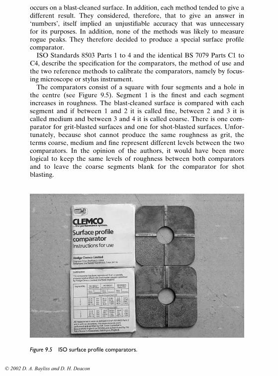
ISO Standards 8503 Parts 1 to 4 and the identical BS 7079 Parts C1 toC4, describe the specification for the comparators, the method of use andthe two reference methods to calibrate the comparators, namely by focus-ing microscope or stylus instrument.
The comparators consist of a square with four segments and a hole inthe centre (see Figure 9.5). Segment 1 is the finest and each segmentincreases in roughness. The blast-cleaned surface is compared with eachsegment and if between 1 and 2 it is called fine, between 2 and 3 it iscalled medium and between 3 and 4 it is called coarse. There is one com-parator for grit-blasted surfaces and one for shot-blasted surfaces. Unfor-tunately, because shot cannot produce the same roughness as grit, theterms coarse, medium and fine represent different levels between the twocomparators. In the opinion of the authors, it would have been morelogical to keep the same levels of roughness between both comparatorsand to leave the coarse segments blank for the comparator for shotblasting.
Figure 9.5 ISO surface profile comparators.
© 2002 D. A. Bayliss and D. H. Deacon

228 Steelwork corrosion control
9.5.1.5 Weld areas
Weld areas are vulnerable and likely to be the first point of failure of apainted structure. Their treatment is often neglected in specifications.References to visual cleanliness, such as Sa2�� or to surface profile arenot applicable.
Often the welding inspector’s requirements are different from those ofthe painting inspector. Most of the chemical contamination will arise fromwelding rods and small portions of the surface should be wetted and testedwith pH papers. Most welding rods give an alkaline deposit which must beremoved before painting, particularly for oleo-resinous paints which couldbe saponified. The major concern with welds, however, is the roughness:sharp edges, undercutting, pinholes, etc., which cannot be coated properlyand must be eliminated.
The International Standard ‘Preparation Grades of Previously CoatedSteel Substrates after Localized Removal of Coating’, ISO 8501 Part 2includes photographs taken from a German DIN Standard,12 which showsexamples of treatment of welds. For this important subject the ISO Com-mittee is producing a standard to illustrate types of surface defects. Thisstandard will use diagrams of the defects and these give a much clearerpicture of each defect than a photograph. Unfortunately, the extent thatsuch defects need not be treated is the subject of a difference of opinionbetween those concerned with paint performance and those concernedwith the integrity of, for example, the welds. There is also a commercialimplication if all specifiers selected the highest standard of treatment forall steelwork regardless of its final use. Both sides have a good case and acompromise has been reached whereby there will be two or three gradesof different degrees of remedying surface defects. It remains to be seenwhen the standard is published, whether specifiers can be persuaded to optfor the lower grades in any circumstances.
NACE has addressed the situation by producing a weld replica in plasticwhich illustrates the varying degrees of surface finish on welds prior tocoating. The weld comparator includes full seam welds, butt welds, lapwelds and skip or tack welds13 (see Figure 9.6).
9.5.1.6 Blast-cleaning operations and equipment
Many specifications rely on the inspection of the final blast-cleaned surfaceas the criterion for acceptance. This is a reasonable approach based on theview that the contractor will have to operate his equipment satisfactorilyin order to achieve these requirements. However, if the contractor’s equip-ment or the operators using it are not particularly efficient, problems anddelay will arise; to avoid this, inspectors may be required to carry outcertain checks. This will be concerned mainly with assessing the quality of
© 2002 D. A. Bayliss and D. H. Deacon

Quality control of coating operations 229
the equipment and its probable effectiveness in achieving the require-ments of the specification.
This section is concerned with blast-cleaning, but hand tools areoften used, particularly for maintenance work, and they should also bechecked, e.g. for wear (in the case of wire-brushes and scrapers). Warpedand blunt tools are much less effective and lead to slower cleaning,so where appropriate suitable action should be taken. Power-driventools should also be inspected and, where necessary, the attachmentssuch as wire-brushes, grinding discs, etc., should be replaced. The hoses,cables and other equipment involved should also be inspected toensure that they are capable of continuous operation and can reach allparts of the structure to be cleaned. Delays due to poor cleaning equip-ment can largely be avoided through careful inspection before the workcommences.
There are two main types of blast-cleaning equipment: one using an aircompressor and the other relying on rotating wheels to provide thecentrifugal force necessary to provide the abrasives with a suitable velocityfor cleaning.
Compressed air blast-cleaning machine. The following general checksshould be made on the compressor and ancillary equipment:
Figure 9.6 NACE weld comparator.
© 2002 D. A. Bayliss and D. H. Deacon

230 Steelwork corrosion control
(a) Correct capacity for the work in hand and ability to maintain therequired air pressure and volume: this can be checked from the manu-facturer’s data sheets.
(b) Compressed air should be free of contaminants and moisture. Thiscan be checked by blowing the air onto a piece of filter paper or whitecloth of suitable size. If there is no discoloration or sign of moisture, thenthe air is clean. On the other hand, a trace of oil or moisture would indi-cate that the various filters and traps are not functioning properly. Seriouscontamination of the test paper or cloth may indicate a requirement forfurther inspection of the air source. Where the specification calls for acomplete absence of moisture in the air, then a change of equipment orthe use of a special drying installation may be called for. The risk of watercondensation carrying through the system increases with increasing rela-tive humidity. When the humidity is high, sometimes the water-separatingdevices cannot cope and the inspector must advise the supervisor.
(c) The blast-cleaning machine should be checked overall, including allthe valves and separators.
(d) The hoses should be of suitable length so that they can be properlyoperated but they should not be unnecessarily long, as this will reduce thepressure available at the nozzle. All couplings should be sound and tight.The pressure at the nozzle can be checked with a special hypodermicneedle gauge which is inserted in the hose close to the nozzle during theoperation of the equipment, i.e. with abrasives being used. The small holewhich is made seals, and does not affect the operation of the hose. Thischeck is easily carried out and will ensure that the machine is operating at asuitable pressure (550–690kPa; 80–100psi) at the nozzle. The pressuregauge on the equipment will indicate the pressure before the air has beenforced through the hoses. The hoses, particularly ‘whip ends’, the smallpieces of smaller-bore hose used at the nozzle end by the blast-cleaner toease handling, will result in some pressure drop. Blast-cleaning may becompletely ineffectual if the pressure at the nozzle is too low. The nozzle isalso important and should be chosen for the specific work in hand. Nozzlesshould be checked for wear and damage; special gauges are available forchecking the nozzle diameter. If badly worn, the nozzle should be replaced.
Centrifugal blast-cleaning machines. Only limited checks can be carried outon this type of equipment, which is in a self-contained unit, without separ-ate compressors, hoses, etc.
(a) Check that the sections to be cleaned can be properly treated. Thearrangement and number of wheels used in the plant will influence thearea cleaned. Adjustments can be made to the equipment but the presenceof re-entrant angles and complexity of shape may result in ‘hidden’ areas,which will have to be blast-cleaned by hand later.
© 2002 D. A. Bayliss and D. H. Deacon

Quality control of coating operations 231
(b) The degree of cleaning is determined to a considerable extent by thespeed of the sections through the machine and, if necessary, this can beadjusted.
(c) The abrasives are recirculated in this type of machine and correctscreening is required to ensure that the specified profile is obtained.
Water jetting. The specification requirements for water jetting have to takeinto account that the standards used for dry blasting, e.g. the SwedishStandard, are not directly applicable to this method of cleaning. Further-more, there is a likelihood of flash rusting on-site from the moistening ofthe surface by the water used for cleaning.
Nowadays, many enlightened paint manufacturers are prepared toaccept a degree of oxidation of blast-cleaned surfaces. To be acceptable,such oxidation should not be powdery and should be ginger in colour andshown to be free of soluble salts. Such ‘gingering’, as it now tends to becalled, is due to the differential aeration corrosion cells formed as cleanwater evaporates from the surface; dark brown rust, particularly in spots,would be an indication of the presence of soluble salts and would be unac-ceptable. Various marine paint manufacturers have produced photo-graphic standards for the visual appearance of suitably cleaned waterjetted surfaces and also the amount of re-rusting that is acceptable. Thoseconsidered the most suitable are incorporated in the new ISO Standard.
9.5.1.7 Abrasives
The degree of inspection will be determined by the specification require-ments and may cover either or both of the following:
(a) Check on type of abrasive, e.g. steel shot.(b) Size of abrasives. This can be checked by suitable screening with
standard sieves, e.g. to BS 410 or ASTM D 451-63.The sample tested must be representative and should not be taken from
the top of the bag where there is likely to be a preponderance of largerparticles. The bag selected for sampling should be representative of thebatch and the contents should be thoroughly mixed prior to the actualtaking of the sample. The test is carried out on the following lines:
(i) A correctly prepared sample of 200g of abrasive is weighed.(ii) The mesh sizes for sieves required for the particular abrasive are
selected by reference to a suitable standard, e.g. BS 2451.(iii) The sieves are arranged in order (they fit together) with the
largest mesh size at the top and the receiver under the smallestmesh size.
(iv) The weighed sample is poured in and vibrated or shaken for 5 min.
© 2002 D. A. Bayliss and D. H. Deacon

232 Steelwork corrosion control
(v) The contents of each sieve are weighed and the weight is expressedas a percentage of the original sample.
(vi) The results are expressed in accordance with the particular standardbeing used.
If the BS 2451 method is used, the results would be expressed as follows.
Taking G24 abrasive as an example: total sample passes 1.00 mm mesh;at least 70% is retained by 0.710 mm mesh; at most 15% passes0.600mm mesh; and none passes 0.355 mm mesh.
All sieves must be cleaned prior to the screening and this is best achievedwith a hand brush. Abrasive should not be pushed from the sieve with apointed metal object as this is likely to damage the mesh and provideincorrect results. The above test can be carried out reasonably quickly butit is sometimes sufficient to screen an unweighed sample of about 400gthrough the largest and smallest sieves only, by shaking for 5min. If all theabrasive has passed through the top sieve and has been retained by thebottom sieve, this would be considered as satisfactory.
(c) Checks for contamination of the abrasive may be called for, particu-larly the presence of dust and oil. Dust can be checked using the sampleprepared for the screening test on sieves. About 100g is placed in a cleancontainer and water is poured in so that the abrasive is just covered. Afterstirring to ensure wetting, any dust from the sample will be visible on thesurface of the water.
The presence of oil can be checked by placing another sample of 100g ina suitably sized glass beaker. Clean solvent, e.g. xylene, is poured so as tojust cover the abrasive; after stirring, some of the liquid is poured carefullyonto a clean glass plate. The solvent is allowed to evaporate and the pres-ence of oil and grease will be detectable on the glass, as a smear. As sol-vents are flammable, suitable safety precautions are necessary whencarrying out the test.
(d) There may be a requirement for a minimum soluble chloride contentwith some abrasives. This can be obtained only by standard analysis in alaboratory.
For a quick check on contaminants, a small sample of the abrasive can bestirred in distilled or demineralised water in a glass container. Spot checkscan then be made for chloride, ferrous ions, etc., or tested in general forsoluble salts with a conductivity test.
There are ISO Standards for abrasives (see Chapter 3, Section 3.2.3.5).These are mainly concerned with laboratory determinations on new abra-sives. Probably the only involvement for a quality control inspector is toensure that samples are obtained correctly.
© 2002 D. A. Bayliss and D. H. Deacon

Quality control of coating operations 233
9.5.2 Testing of liquid paints
Increasingly, and particularly for important projects, paint users are check-ing the quality of paint materials prior to work starting and during thework. Most of the tests must be carried out in a laboratory (see Chapter16), but the painting inspector is frequently required to obtain samples andalso to carry out some simple tests on site.
Sampling is generally by selecting unopened tins at random from stock.If samples are required from large containers, it is important to ensurethat sampling is carried out correctly, for example to ISO 1512 :1991 Paintand Varnishes, ‘Samples of products in liquid or paste form’ and ISO 1513‘Examination and preparation of samples for testing’. Special deliveries ofsingle tins of paint arranged by the contractor are generally not acceptableas a representative sample.
On-site, a painting inspector may be required to check paint supplies fortype, colour, suitability for the chosen method of application, condition,gravity and viscosity. These latter methods are described in Chapter 16.
As the work proceeds, and particularly with brush application, theinspector may take samples from painters’ ‘kettles’ for gravity checks.These will indicate whether unauthorised thinning has been performed.Results should be within 10% of the paint manufacturers’ declared figuresbut in practice, if thinning has occurred, it is likely to be so gross as to beobvious. The tests are generally only required to give a scientific basis forthe complaint against the applicator. Fortunately, although this was acommon fault in the past, it is less likely with spray application since exces-sive thinning gives the operator little advantage.
9.5.3 Coating application
The quality of the coating application has an important influence on thedurability of coatings and sound inspection techniques will play an import-ant role in ensuring that application is carried out to the required highstandard. Inspection should cover not only the physical application of thecoating but other aspects which also affect the quality of the final coating.These include checks on the ambient conditions at site or in the shop tomake sure that they satisfactorily meet the specification requirements andalso checking of paints, including storage and mixing. The application ofmetal coatings also requires inspection and the inspection methods will bedetermined by the method of application and the particular metal beingcoated.
Good housekeeping has an important influence on the quality of workand the inspector should endeavour to ensure that as high a standard aspossible is maintained and should seek the cooperation of the contractor’ssupervisor in this respect.
© 2002 D. A. Bayliss and D. H. Deacon
234 Steelwork corrosion control
9.5.3.1 Storage and preparation of paint
The following checks are necessary to ensure that the paint is correctlystored and prepared to use:
(a) Paint delivered to the site corresponds to the specification require-ments, including type, e.g. primer, and colour.
(b) All paints are correct for the method of application to be used, e.g.airless spray.
(c) Condition of storage: a properly prepared store that does not sufferfrom extremes of temperature should be used. When not in use it shouldbe locked and the key held by a responsible person.
(d) Batch numbers should be recorded and paint should be withdrawnfrom store in the correct sequence. Withdrawals should be properlyrecorded.
(e) Sufficient paint should be available in store, either on-site or at acentral depot, for completion of the work.
(f) The inspector should be present when paint is issued at the start ofthe work period.
(g) Single-pack paints must be thoroughly stirred. This particularlyapplies to paints containing heavy pigments such as micaceous iron oxideor zinc dust.
(h) Two-pack materials must be mixed strictly in accordance with thepaint manufacturer’s data sheets. Furthermore, other requirements such asinduction periods and pot life must be strictly adhered to. Material mustnot be used after the expiry of its pot life; it must be discarded. Tempera-ture has an effect on pot life. If the temperature is markedly higher thanthat quoted on the paint data sheets, the pot life may be decreased andadvice should be sought if any doubts exist regarding this aspect.
(i) Additions to paints must be strictly in accordance with the manu-facturer’s recommendations. Too much thinner will result in reduced filmthickness, too little may cause dry spray, pinholes or poor appearance. Thewrong type of thinner, i.e. one other than that given in the manufacturer’sdata sheet, may cause coagulation of the paint. In some cases, this can bequite spectacular as the coating gels in the spray lines.
(j) If test results on paints are required before painting commences, itmust be checked that they are available and have been submitted to theclient.
9.5.3.2 Paint application equipment
All equipment must be in good condition if sound paint coatings are to beachieved. Brushes and rollers should be of the correct size and shape andmust not have worn to an extent where coating application will be
© 2002 D. A. Bayliss and D. H. Deacon

Quality control of coating operations 235
affected. All spray equipment should be checked to ensure that it is insound working condition and that reserve equipment is available ifrequired.
The information in the manufacturer’s paint data sheets should be fol-lowed regarding pressure, tips, etc. Where appropriate, hoses, filters andcompressors should be examined to ensure that they are in sound con-dition and suitable for the work in hand. All the equipment must be cleanand should be thoroughly checked before operations are started.
The condition, cleanliness and suitability for the work to be carried outare essential requirements for paint application equipment and must bethoroughly assessed and checked beforehand. The lack of suitable equip-ment or its malfunctioning can lead to serious delays or poor applicationof the paint, both of which will add to the overall costs.
9.5.3.3 General conditions in the shop and on the site
The suitability of any workplace for proper paint application should beassessed prior to placing a contract. However, this is often not done andthe inspector should then satisfy himself that the conditions in the shop aresuitable for the work in hand. The various requirements can be summar-ised as follows:
(a) Maximum and minimum temperatures and their control. Suitabilityof equipment for eating, e.g. combustible products should not be producedinside the shop.
(b) Ventilation: sufficient to maintain low concentration of fumes andvapours; solvent vapours must be kept below the TLV (threshold limitvalue) or Occupational Exposure Standard.
(c) Lighting: sufficient intensity to allow for adequate painting andinspection.
(d) Positioning of various pieces of equipment, e.g. blast-cleaning areasmust be properly separated from painting areas to avoid contaminationwith dust, abrasives, etc.
(e) Suitable areas for storage of painted steel and adequate equipmentfor handling the painted product.
(f) Availability of proper protective equipment for operators.(g) Sound health and safety procedures.(h) At site, as opposed to inside a shop, there can be no direct control of
the ambient conditions. However, where protective sheeting has beenspecified, e.g. to allow for the continuation of work during adverseweather conditions, the adequacy of such measures should be checked.
(i) There must be adequate access to all surfaces to be painted but asituation frequently overlooked is when parts of the scaffolding (albeitonly relatively small areas) are fixed too close to the work surface.
© 2002 D. A. Bayliss and D. H. Deacon

236 Steelwork corrosion control
The storage conditions for painted steelwork coming to the site should besuitable, with proper foundations for the stacked steelwork, ensuring thatsections are not resting in mud or on gravel which can damage the coating.The sections should be stored to avoid ponding, i.e. collection of water onhorizontal areas. Suitable slings, etc., should be available for handling.
9.5.3.4 Measurement of ambient conditions
Specifications may require paint application to be carried out undercertain ambient conditions and the inspector will need to measure andassess these requirements. The conditions generally taken into account arethose appertaining to air temperature, steel temperature, relative humidityand dew point.
Air temperature and relative humidity can be measured automaticallyusing recording hygrographs and thermographs, which record the informa-tion on charts to provide daily or weekly records. These instruments maybe operated by clockwork or electrically. Generally, however, for inspec-tion work, various forms of hygrometer and thermometer are used.Hygrometers, or psychrometers as they are also known, are instrumentsfor measuring the relative humidity indirectly. The readings obtained withthese instruments provide wet and dry bulb temperatures and these areconverted to relative humidities by reference to suitable tables. The mostcommonly used instrument of this type is the whirling hygrometer or slingpsychrometer, as it is called in some parts of the world. Relative humidityand dew point are important requirements for satisfactory paint applica-tion and their influence has been considered in Chapter 5. As both arequoted in specifications, the inspector must have suitable and convenientmethods for measuring them. ISO 8502/4 is a guide to the estimation ofthe probability of condensation on a surface to be painted.
Whirling hygrometer. The whirling hygrometer (see Figure 9.7) containstwo identical thermometers, one of which is covered with a small piece offabric or wick which is saturated with water; this is called the ‘wet bulb’, theother being called the ‘dry bulb’. The dry bulb records the ambient temper-ature and the wet bulb records the effects of water evaporating from thewick. The rate of evaporation is influenced by the relative humidity whichindicates the amount of moisture in the air. The lower the humidity, thefaster is the evaporation rate. The two temperatures are then comparedwith standard tables which provide a figure for relative humidity.
Certain precautions are necessary with the operation of these hygro-meters. They should be examined before use and continuity of themercury columns in the thermometer checked. The fabric covering thewet bulb should be clean, secure at both ends and wet. The small containerin the instrument should be filled with distilled water.
© 2002 D. A. Bayliss and D. H. Deacon

Quality control of coating operations 237
The following sequence is used for measuring the relative humidity withthis type of hygrometer:
(i) With the hygrometer prepared for the measurements, it is rotatedor whirled at about 180 rpm, or slightly faster, for 20 seconds.
(ii) In a still atmosphere, the operator should walk slowly forwardduring the whirling operation to avoid any effects from his body.The operation is best carried out away from direct sunlight.
(iii) The temperatures on both thermometers are noted, the wet bulbfirst, immediately after the completion of 20 seconds of whirling.
(iv) The whirling is repeated for another 20 seconds at the same speedas before.
(v) Both temperatures are read.(vi) The procedure is continued until the temperature reading on each
thermometer is constant for two successive operations.(vii) The two temperatures are recorded.
(viii) Suitable meteorological tables, supplied by national authorities inmost countries, are consulted. The relative humidity and dew pointcan then be read from the tables.
The whirling hygrometer may not operate satisfactorily if the air tempera-ture is below freezing point (0°C) and other methods such as direct-reading instruments may be required. These are, however, expensive and
Figure 9.7 Whirling hygrometer.
© 2002 D. A. Bayliss and D. H. Deacon

238 Steelwork corrosion control
are not usually considered to be a necessary part of an inspector’s equip-ment. Digital instruments, which give instant readings of the dry and wetbulb temperatures (see Figure 9.8), and electrically operated instrumentswhich incorporate a fan to draw air across the wet bulb are available.These instruments can give substantially different readings from thewhirling hygrometer and this can be the cause of dispute between inspec-tor and contractor. The probable reason for this is that the static apparatussamples a smaller and more localised quantity of air. Some of the elec-tronic types can be calibrated with standard humidity cells but this merelyestablishes the precision of the instrument not the accuracy of the determi-nation. Obviously, the whirling hygrometer is more dependent on itscorrect use by the operator. However, if the standard procedure is fol-lowed and the operator continues to take measurements until the readingsstabilise, then this apparatus, however cumbersome and old-fashioned itlooks, is a standard reference method.14
9.5.3.5 Measurement of steel temperature
Specifications commonly require that steel temperatures should not beless than 3°C above the dew point, to avoid the possibility of moisturecondensing on the surface during painting operations. It is, therefore,
Figure 9.8 Electronic relative humidity and dew point gauge.
Source: Elcometer Instruments Ltd.
© 2002 D. A. Bayliss and D. H. Deacon

Quality control of coating operations 239
necessary to have a simple means of measuring the steel temperature. Thisis usually measured with a contact thermometer which has magnetsattached for fixing to the steel. The thermometer contains a small bimetal-lic couple which acts in a way similar to a thermocouple and records thetemperature on a dial. These instruments are normally cheap but somemodels can be very inaccurate. Each instrument should be checked beforeuse and, since there is generally no method of calibration, discarded ifmore than 10% out.
Digital temperature gauges with separate probes are available whichprovide a direct reading of the surface temperature in a matter of 20seconds compared with a stabilisation time of as much as 30 min with thedial type, and with greater accuracy. However, these instruments are notnecessarily intrinsically safe and may not be permitted for use in haz-ardous areas.
9.5.3.6 Measurement of paint film thickness
A range of instruments is available for the measurement of dry film thick-ness. Provided they are regularly and correctly calibrated and used pro-perly, they will provide reasonably accurate measurements of thickness.Other qualitative methods are used such as adjusting the opacity of thepaint so that the underlying coat is just obscured when the correct coatingthickness has been applied. Again, strong contrasts between successivecoats enable both the painter and the inspector to check on the continuityof coatings and to ensure that all coats in a system are in fact applied.
Apart from checking dry film thickness, tests can be done to determinethe thickness of the wet film and this has the advantage that adjustmentscan be made immediately. It is often assumed that provided the minimumthickness of coating is attained, then additional thickness is advantageousto the client. This is not always correct, however, and in some cases amaximum thickness may be specified. Clearly, problems arise if the dryfilm is greater than this.
Wet film thickness measurement. For paint applied to steel surfaces, thismethod is used mainly as a guide to the painter and the inspector; dry filmthicknesses are usually specified. Wet film thicknesses are most commonlymeasured with a small comb gauge. This has a number of projectionssimilar to a comb. The two at the end are the same length and those inbetween progressively vary in height (see Figure 5.). The gauge is pressedinto the wet film perpendicular to the surface with the two end pieces incontact with the steel surface. It is then removed and examined. Some ofthe teeth will have been wetted by the paint whereas others will haveremained proud of the surface of the paint coating, so will not have beenwetted. Each of the teeth or graduated steps is designated by a thickness in
© 2002 D. A. Bayliss and D. H. Deacon

240 Steelwork corrosion control
micrometres (or mils) and the thickness is taken as being the average ofthe highest step covered and the lowest one not covered, e.g. if the 50µmstep is wetted and the 75µm step is not, then the thickness is considered asbetween those two measurements. A range of gauges is available, so ifnone of the teeth is wetted, another gauge should be used. Gauges areavailable in stainless steel and these must be cleaned after use. Disposableplastic gauges are also used.
Another type of wet film thickness gauge consists of a wheel with twoouter rings of equal diameter with a graduated eccentric centre ring. Thegauge is held between a finger and thumb and rolled over the paintedsurface. The inner ring is then examined and the thickness is indicated bythe graduation mark where the paint no longer wets the ring.
The wet film thickness is only useful if it can be related to the dryfilm thickness. The ratio is as follows: dry film thickness�wet film thick-ness�% solids (vol)÷100.
Dry film thickness measurement. The specification may call for a minimum,average or maximum thickness, but the specifier should take into accountthe inevitable variations in film thickness that occur in practice andprovide a realistic requirement for film thickness. Otherwise, unnecessaryproblems are likely to arise during inspection.
Many instruments have been developed for the measurement of dry filmthickness. Only those commonly used in high-quality inspection will beconsidered here. The instruments can be used for measuring the thicknessof metal coatings on steel, with certain limitations, as well as paintcoatings.
The non-destructive method most commonly used depends upon mea-suring the magnetic flux between the instrument probe and the ferroussubstrate. The weaker the flux, the bigger the gap and therefore thethicker the apparent coating. The instruments are divided into three broadtypes: (a) magnetic pull-off, (b) fixed probe, and (c) electronic induction.All of these instruments, to varying degrees of accuracy, operate on theprinciple of the coating acting as an air gap, and this gives rise to errors.Rust, millscale, dirt, vacuoles, etc., will add to the apparent coating thick-ness. Measurements on very soft paint films will give low results. This canbe counteracted by making measurements over a calibration foil of knownthickness. This spreads the load of the probe and prevents indentation.Obviously the thickness of the foil is then subtracted from subsequentreadings. There are other factors which may influence readings. There canbe appreciable differences in the magnetic properties of steels of differentcomposition. Differences between most low-carbon steels are probablyinsignificant but may be greater in higher alloy steels. It is always advisablethat the gauge should be calibrated on the same type of steel to which thecoating is to be applied.
© 2002 D. A. Bayliss and D. H. Deacon

Quality control of coating operations 241
Magnetic gauges are also sensitive to geometrical discontinuities, suchas holes, corners or edges. The sensitivity to edge effects and discontinui-ties varies from gauge to gauge. Measurements closer than 25 mm from thediscontinuity may not be valid unless the gauge has been calibrated forthat location. Some of the electronic gauges may be sensitive to the pres-ence of another mass of steel close to the body of the gauge. This effectmay extend as much as 75mm from an inside angle.
Magnetic gauge readings will be affected by the curvature of the surface.This may be overcome by calibrating the gauge on a similarly curvedbut uncoated surface. All probes of these instruments must be held per-pendicular to the surface to provide valid measurements. Strong magneticfields, as from welding equipment, can interfere with the operation of elec-tronic gauges. Residual magnetism in a steel substrate can affect the result.Most magnetic gauges operate satisfactorily between 4°C and 49°C.However, if such temperature extremes are met in the field, the gaugeshould be checked with at least one thickness reference standard afterboth the standard and the gauge are brought to the same ambient temper-ature. Since tolerance to the above effects can vary considerably betweenmakes of instrument, the manufacturer’s instructions should be followedcarefully.
The most difficult problem is the interpretation of results over a blast-cleaned surface. A rough surface alone, without any paint, will give areading on the instrument of anything from 15 to 50µm, depending on theroughness.
Since with thin films, in particular, it is necessary to know the film thick-ness above the peaks of the profile, allowance must be made for this in theinstrument reading. Opinions differ as to the best way this should beaccommodated and in fact different makers of the same types of instru-ment give different advice. The most usual methods are as follows:
(i) Place a shim of known thickness, appropriate to the film to be meas-ured, on the unpainted blast-cleaned surface and adjust the instru-ment to read the shim thickness. All subsequent measurements onthat surface can then be read directly.
(ii) Place an appropriate shim on a polished flat steel plate and calibratethe instrument. Then take a number of measurements directly fromthe blast-cleaned surface. Obtain an average figure which can beused as a factor to be subtracted from all future results on thatsurface.
(iii) Assess the roughness of the blast profile by use of the ISO Com-parator (see Chapter 3, Section 3.1.4) and allow a correction factordepending upon the Comparator grade of roughness, for exampleminus 10 µm for a ‘fine’ profile, minus 25µm for a ‘medium’ profileand minus 40µm for a ‘coarse’ profile.
© 2002 D. A. Bayliss and D. H. Deacon

242 Steelwork corrosion control
Of the three methods, the third is recommended for most situations. Theproblem with the first method is that shims are likely to deform under thepressure of the instrument probe. Also, the roughness of any blast-cleanedsurface is very irregular and the calibration could be made over an areathat was unrepresentative.
The ease and accuracy with which instruments can be adjusted varieswith type and make, and manufacturer’s instructions should be followed.The various types will be discussed separately.
There are relevant ISO Standards as follows: ISO 2178 ‘Non-magneticCoatings on Magnetic Substrates–Measurement of Coating Thickness –Magnetic Method’ describes the limitations of dry film thickness gauges.ISO 2360 ‘Non-conductive Coatings on Non-magnetic Basic Metals’is concerned with the eddy current method and ISO 2808 ‘Paints andVarnishes. Determination of Film Thickness’ describes several dryfilm thickness measurement methods. SSPC (The Steel StructuresPainting Council, USA) have also produced a comprehensive specificationPA2 ‘Measurement of Dry Coating Thickness with Magnetic Gauges’.This includes recommendations for the number of measurements neces-sary for conformance to a thickness specification. This is importantbecause it is impossible to apply coatings to a strictly uniform thickness,particularly if they are applied as thick films. Paint manufacturers’data sheets often give a recommended film thickness but without specify-ing whether that is a minimum or average value. Most engineers interpretit as a minimum, but this does raise the average significantly, whichmay not always be desirable. Film thicknesses can be quoted as ‘nominal’.The definition is that over any square metre the average of the readingstaken should equal or exceed the nominal thickness and in no caseshould any readings be less than 75% of the nominal thickness. The disad-vantage of this definition is that it does not allow for even one rogueresult from the instrument and does not define a maximum thicknesspermissible.
Concerning frequency of measurement, the SSPC specification statesthat for structures not exceeding 300 ft2, five measurements should betaken over an area of 100 ft2 spaced evenly over the area, each reading tobe the average of three readings taken close together. The average of thefive readings should be not less than the specified film thickness and anyone reading (an average of three determinations at one spot) should notbe less than 80% of the specified thickness. For larger structures thenumber of sampling areas is proportionally increased.
The SSPC specification also describes the different types of magneticinstrument available and suggests their method of calibration. Some oftheir recommendations differ from those given by the instrument manu-facturers and it is understood that the subject is under review. ISO 12944has similar recommendations (see Table 9.1).
© 2002 D. A. Bayliss and D. H. Deacon

Quality control of coating operations 243
Magnetic pull-off. There are a number of instruments in this category andthey are known by various names according to the country of supply.However, they can be sub-divided into a number of groups, the simplest inoperation being the Pencil Pull-off or Tinsley Gauge. This is the size of asmall pencil, with a clip attached for placing in a pocket. The principle ofoperation is straightforward, with a magnet attached to a spring held in ahousing and a reference mark that moves along a scale. When the forceexerted by the spring balances the magnetic attraction, the magnet pullsfrom the paint film and a small marker can be read from the scale. Theinstrument must be used perpendicularly to the painted surface under test.These instruments are cheap and easily carried about, but the operatingprinciple makes accurate measurement difficult to achieve.
Another instrument of this type works in a somewhat more complexway but again relies upon the tension in a spring. A hair spring is con-nected to a lever at the fulcrum and fitted to the instrument housing, theoutside of which carries a marked dial fixed to the lever. The instrumentlever has a small magnet at one end which protrudes through the casingand is counterbalanced at the other end. The instrument is placed on thecoating and the dial is rotated so that the spring tension is increased to aposition where the magnetic force balances the spring tension. The mag-netic force is, of course, related to the effect of the coating thickness,which acts as an air gap. Just beyond the balancing point the small magneton the lever springs from the surface and the dial reading, in microns ormils, provides a direct reading of the coating thickness. Errors that canarise with this instrument include:
(i) Use on overhead surfaces, which may produce inaccurate readings.(ii) The effect of vibration in the area of testing may cause loss of mag-
netic attraction between the magnet in the instrument and the steelsurface. This can result in readings that are too high.
(iii) If paint films are soft or tacky, the magnetic probe of the instrument
Table 9.1 Measurement and acceptance criteria of the dry film thickness and for thefrequency of measurement
Area/length of inspection area/ Minimum numberdifficult area of measurements(m2 or metres)
up to 1 41–3 103–10 1510–30 2030–100 30above 100 add 10 for every additional 100m2
© 2002 D. A. Bayliss and D. H. Deacon

244 Steelwork corrosion control
may press into the film and produce a low reading of the true filmthickness.
(iv) If the probe is not regularly cleaned, metallic abrasives may accu-mulate at the magnetic tip and lead to incorrect readings.
Fixed probes(i) Twin fixed probe. These were one of the original types of paint filmthickness instruments. They rely on permanent magnets within the instru-ment casing. Nearby strong magnetic fields, as for example from weldingequipment or nearby power lines, will interfere with the reading. It isrecommended in all cases that two readings are taken, the second with theprobes turned by 180°.
(ii) Single fixed probe. This instrument functions mechanically on a self-balancing magnetic principle. The fixed jewelled tip probe is placed on thecoating and a digital reading is obtained from a revolving mechanical device.
Electronic type. Electronic gauges use either electromagnetic induction orHall-effect probes to measure non-magnetic coatings on a ferrous substrate15
(see Figures 9.9 and 9.10). The maximum coating thickness that can be meas-ured with both types depends on their size and design. Typical thicknessranges are: 0–250µm for small probes, 0–1500µm for standard size probesand right angled configurations, 0–5000µm (0–5mm) for probes used with
Figure 9.9 Basic electronic thickness gauge.
Source: Elcometer Instruments Ltd.
© 2002 D. A. Bayliss and D. H. Deacon

Quality control of coating operations 245
fire-resistant coatings, 0–13000µm (0–13mm) for large probes used forfoamed coatings. To measure non-conductive coatings on non-ferrousmetals, an eddy current gauge is used. Electronic gauges vary with manu-facturer, some or all of the following features could be included:
(a) Digital display of thickness readings.(b) Memory for calibration settings.(c) Integral probes for one-handed operation or separate probes for areas
of difficult access.(d) Statistical calculations of mean value to characterise a set of readings,
standard deviation to assess the spread of a set of readings, highestand lowest readings to assess the range of values, and number of read-ings to determine the validity of the sample.
(e) Batch storage of readings to keep different sections of work separate.(f) Data transfer to a printer or computer for record-keeping and further
analysis.(g) Date and time marking of readings.
Figure 9.10 PosiTector 100 – a non-destructive gauge measuring coating thickness onvarious substrates, using ultrasonic technology.
Source: DFT Instruments Ltd/De Felsco Inc.
© 2002 D. A. Bayliss and D. H. Deacon

246 Steelwork corrosion control
Other instruments and methods for assessing dry film thickness. The instru-ments considered above are, in various forms, those most commonly usedfor measuring the dry film coating thickness. They are all non-destructiveand this is an advantage. However, there are also instruments that requirea small cut in the paint film and could be called ‘destructive’. This wouldbe correct but gives the wrong impression because, with most coatings, thesmall area of damage can be repaired without difficulty. However, it is nota routine measurement and should not be undertaken unless specified.Otherwise the contractor is liable to claim compensation for the repair ofdamage, however small. The method is mainly used when disputes arise oron non-metallic substrates.
The principle of operation is based on viewing a small cut or a smallconical drill hole made in the coating at an angle, using a small microscopeheld perpendicular to the surface of the coating. A graticule is incorpo-rated into the eyepiece and this allows measurement of the coating thick-ness. Cutting devices with different angles are available and simpleconversions can be made to determine the value of the graticule gradua-tions. This information is supplied with the instruments. The conical holeis made by a small hand-rotated drill which must be operated to removethe coating to the steel base. The other type relies upon a knife-type cutand, on brittle materials, it may be difficult to provide a sharp cut; thedrill-type may be preferred. The advantages of these instruments lie intheir ability to provide a measure of the individual coatings in a system.This cannot be achieved with magnetic instruments which provide a mea-surement for total thickness only, although the individual thickness ofcoatings can be measured during application.
Coating thickness can also be calculated from the amount of paintapplied to a known area of steelwork. This method is not generally usedfor inspection purposes but is employed in some maintenance and generaltesting work.
9.5.3.7 Detection of discontinuities in coatings
Obviously, there is a tendency for applicators to miss areas that are outof sight or have difficult access. An important qualification for apainting inspector is ability and willingness to climb and work at heights.Observation by binoculars from the ground has limited value. Withfairly close access, the use of a small angled mirror attached to a tele-scopic handle is useful for getting into awkward areas, undersides ofpipes, etc. Some consider that the mere visible possession of such aninstrument by the inspector has a worthwhile psychological effect on thepainters.
Other discontinuities can be difficult to detect visually, for exampleporosity due to dry spray, or minute slivers of steel penetrating from the
© 2002 D. A. Bayliss and D. H. Deacon
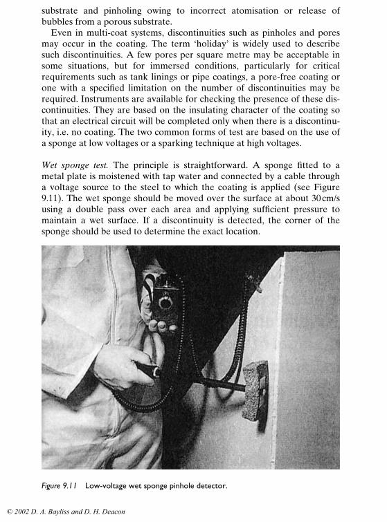
Quality control of coating operations 247
substrate and pinholing owing to incorrect atomisation or release ofbubbles from a porous substrate.
Even in multi-coat systems, discontinuities such as pinholes and poresmay occur in the coating. The term ‘holiday’ is widely used to describesuch discontinuities. A few pores per square metre may be acceptable insome situations, but for immersed conditions, particularly for criticalrequirements such as tank linings or pipe coatings, a pore-free coating orone with a specified limitation on the number of discontinuities may berequired. Instruments are available for checking the presence of these dis-continuities. They are based on the insulating character of the coating sothat an electrical circuit will be completed only when there is a discontinu-ity, i.e. no coating. The two common forms of test are based on the use ofa sponge at low voltages or a sparking technique at high voltages.
Wet sponge test. The principle is straightforward. A sponge fitted to ametal plate is moistened with tap water and connected by a cable througha voltage source to the steel to which the coating is applied (see Figure9.11). The wet sponge should be moved over the surface at about 30 cm/susing a double pass over each area and applying sufficient pressure tomaintain a wet surface. If a discontinuity is detected, the corner of thesponge should be used to determine the exact location.
Figure 9.11 Low-voltage wet sponge pinhole detector.
© 2002 D. A. Bayliss and D. H. Deacon

248 Steelwork corrosion control
The coating acts as an insulator so that current does not flow unlessthere is a discontinuity such as a pinhole present. In this case, the circuit iscompleted and a device in the circuit, e.g. a lighted bulb or an audiblesignal, operates to indicate the presence of a discontinuity in the film.
The voltages vary with different types and makes of instrument, butthey generally range from 9V to 90V, the higher voltage being used forthicker coats.
Although simple in operation, certain precautions are necessary. Thesponge must be sufficiently wet to allow proper operation but excess mois-ture on the surface or in the atmosphere may give rise to ‘tracking’, i.e. thewater will conduct current to a pinhole some distance from the sponge.The coating to be tested should also be dry to eliminate tracking. The useof a weakened detergent solution, e.g. ‘Teepol’, may be advantageous,particularly for coatings of thicknesses above 250µm.
The advantage of the method is that it cannot harm the coating. The dis-advantage is that it is only effective at film thicknesses less than 500µm.
High-voltage test. Although the principle is the same as for the low-voltagetest, no sponge is used; instead a wire brush or other conductive electrodeis used (see Figure 9.12). These instruments are generally either DC or DCpulsed type. A direct-current apparatus provides a continuous voltage; a
Figure 9.12 Holiday detector, ‘spark tester’.
Source: Elcometer Instruments Ltd.
© 2002 D. A. Bayliss and D. H. Deacon

Quality control of coating operations 249
pulsed type discharges a cycling high-voltage pulse. Both types can accom-plish the desired result but the pulsed type is considered more suitable forthe thickest films. The DC voltage is variable up to about 30 kV, depend-ing on the type of instrument. The circuit is similar to that used with thelow-voltage system, with one end of a cable fixed to the steel structure andthe other end to the electrode. This is passed over the surface of thecoating at approximately 30 cm/s using a single pass. At a discontinuity aspark jumps, completing the circuit.
At the high voltages used, these instruments are capable of burningholes in the coating, so they must be used with discretion and only at thevoltage recommended by the coating manufacturer and as stated in thespecification. In situations where no voltage setting is specified, then a rea-sonable procedure to follow is: to use the ratio of 100V per 25µm of thenominal coating thickness, since most coatings have quite high dielectricbreakdown strengths with 500V to well over 2000V per 25µm being quitecommon. Even materials with relatively low dielectric breakdownstrength, such as glass-fibre reinforced polyesters, would require 43kV tobreak down a 3 mm coating. Reducing this by one-third gives 14 kV as atest voltage, which would present no danger of destruction to properlycoated areas.
In the absence of any knowledge of the coatings or the instrumentvoltage outputs, the best method is to make a very small hole in thecoating and starting with the apparatus at its lowest voltage, increase untilthe test hole is consistently detected.
Many applicators are strongly opposed to this test, with some justifica-tion if it is incorrectly carried out. However, much of the suspected coatingbreakdown is due to incorrect use of the apparatus, non-uniform thick-ness, voids, vacuoles or dirt inclusions in the coating. Retained solventscan also give erroneous indication.
Re-testing should not result in more indications of discontinuities thanpreviously unless the speed of testing or test voltage has been changed orthe coating has been in service or stressed so that its dielectric strength islower.
Devices using AC current are less common but have an application forthe testing of coatings that are conductive, for example coal-tar epoxies orrubber linings that contain carbon black pigment. The apparatus is notdirectly connected to the substrate but emits a blue corona which whenpassed over the coating surface will cause a spark to jump from the tip ofthe probe to the discontinuity. Surface contaminants and moisture can alsocause the apparatus to spark. Since there is a higher risk of a severe elec-tric shock from this apparatus, it requires greater care in handling.
© 2002 D. A. Bayliss and D. H. Deacon

250 Steelwork corrosion control
9.5.3.8 Adhesion
Testing of coating adhesion is another destructive test that the inspectormay be called upon to carry out in the event of a dispute. There are twotypes of adhesion test that can be carried out in the field. These causesmall areas of damage to the coating and should only be carried out byagreement with all concerned. One method involves cutting a patternthrough the film with a knife and assessing the amount of detachment ofthe film that this causes. For example, there is the Cross-Cut Test asdescribed in ISO 2409 and ASTM D 3359. This requires a matrix of cuts toproduce even squares. The cuts can be made individually or by using amulti-blade cutter. The spacing of the cuts and the similar ones at rightangles, and hence the size of the squares formed, is determined accordingto the thickness of the coating. Adhesive tape is applied to the cuts andpulled away sharply. The amount of detachment is rated according to thescales illustrated in the standards.
The other cutting method, called the X-Cut – or St Andrew’s Cross – issimpler, but requires an even more subjective assessment and simplyinvolves making two knife cuts, each about 40 mm long and with thesmaller angle between the cuts of between 30° and 45°. Again adhesiontape is applied and then pulled away and the adhesion rated according tothe amount of paint film detached. Probing the cut edge with a knife cangive erroneous results because the amount of detachment can dependupon the cohesive strength of the film.
The other type of adhesion test method uses a pull-off principle. Itinvolves sticking a test dolly to the coating with a suitable adhesive andmeasuring the force required to detach the dolly and the coating, or partof the coating, from the substrate. There are several proprietary makes ofthis type of adhesion tester on the market using different methods to exertthe force, for example: compressed spring assemblies, hydraulic pressure(see Figure 9.13) and pneumatic pressure. They are normally calibrated todisplay the force per unit area, taking into account the area of the face ofthe dolly that was stuck to the coating. This type of method, that couldpossibly be considered non-destructive, involves using a tensile testmethod to apply force to the dolly, but in this case the dollies are made tobreak at a certain force. It therefore becomes a go/no-go test.
It is then possible with a shear force to remove the dolly without damag-ing the coating. Each of the test instruments are affected by differentfactors, but some are common, for example:
(a) Low results will be obtained unless the coating is adequately curedbefore testing. With some two-pack epoxies, this may take severalweeks, or even months before optimum strength is reached.
(b) The thickness of the substrate affects the result, for example, adhesive
© 2002 D. A. Bayliss and D. H. Deacon

Figure 9.13 Hydraulic adhesion testing gauge.
Source: Elcometer Instruments Ltd.
© 2002 D. A. Bayliss and D. H. Deacon

252 Steelwork corrosion control
rates for the same material can be nearly 60% higher on a plate 12mmthick, than on a plate 5 mm thick.
(c) The force must be applied smoothly to the dolly. Jerky or unevenapplication can cause premature failure.
(d) The force must be normal to the surface.(e) The rate of the application is also critical and, in general, the full force
should be applied quickly, for example, within 100 seconds.(f) The dolly must not be applied to an uneven coating surface, for
example, one with sags, runs and dry overspray.(g) If the coating is glossy it should be lightly abraded and the face of the
dolly should be abraded to remove all glossiness or old adhesive.(h) The coating around all parts of the dolly adhering to the surface must
be scored, otherwise the measurement will be of the cohesive strengthof the film not the adhesion.
(i) Hydraulic instruments tend to pull from the centre of the dolly, pro-viding results of a higher order and lower standard deviation.
If the dolly fails at the adhesive level, the test is invalid and mustbe repeated. If it fails within the coating system this is a cohesive failureand will usefully indicate a weakness within a multi-coat system. If itfails at the coating/substrate interface, this is a measure of the coatingadhesion.
9.5.3.9 Tests for cure
An inspector may be required to carry out hardness tests on a coating inorder to establish whether it is adequately cured.
A pencil hardness test is frequently specified for thin stoved finishesand occasionally for air-drying finishes. The method consists of pushingpencils of increasing hardness across a paint film until one is foundthat scratches the paint film. In the USA the opposite technique isemployed, so that the hardest pencil is used first and then in decreasinghardness until one is found that does not scratch the coating. The resultwill depend upon the make of pencil used, the pressure applied and theinterpretation of whether the coating is scratched or not. It can only beconsidered a rough indication. Fish16 has reported in work for ISO stan-dardisation that even using one manufacturer’s pencils, the test did notgive consistent results.
For thick coatings, in excess of 800µm, there are hand-held portablehardness testers. The two most commonly used for testing the cure of elas-tomeric coatings are the Barcol hardness tester and the Durometer. Bothof these instruments have models in a suitable range for testing soft plas-tics. The testers are held against the coating surface and a spring-loadedplunger is driven into the coating. When the resistance of the coating
© 2002 D. A. Bayliss and D. H. Deacon

Quality control of coating operations 253
equals that of the spring then a reading can be taken from the dialindicator on the instrument. Results are normally given in hardness for theparticular instrument. Hardness results from different makes of instru-ment generally cannot be directly correlated. Therefore, both instrumentand hardness required must be specified.
Another test for cure of coatings is the solvent sensitivity test or solventwipe test. It can be used on chemically cured coatings such as epoxies butis frequently used to ensure the complete hydrolysation of inorganic zincprimers. There are several slightly different methods of carrying out thetest, so the method required should be detailed in the specification. Onemethod is to saturate a rag in solvent. The choice of solvent can make adifference to the result and should be checked with the paint manufacturerif not specified. The saturated rag is then wiped across the surface of thecoating for a specified number of times. If the coating is not properlycured, it will stain the rag quite readily. If only a trace, or none, of thecoating comes off on the rag, this will at least indicate that the surface ofthe coating is cured.
9.6 Inspection of metal coatings
There are fewer stages in the application of metal coatings so inspection isusually more straightforward than with paint coatings. There are fourmethods of applying metal coatings to constructional steelwork, or thecomponents used in conjunction with it:
(i) diffusion, e.g. sherardising of zinc.(ii) electroplating.
(iii) hot-dipping.(iv) spraying.
(i) and (ii) are usually factory-applied coatings and inspection is not nor-mally carried out during the processing. The thickness of electroplatedcomponents on steel can be checked using the magnetic-type instrumentsemployed for paints. Diffusion coatings contain a series of iron-basedalloys, so usually the thickness cannot be determined with any accuracyusing such instruments.
Hot-dip galvanised coatings also contain alloy layers, so again problemsmay arise when measuring the thickness with magnetic instruments. Inpractice, these instruments are used for determining the coating thicknessof hot-dipped zinc coatings. This may be acceptable as a control checkwhere a series of steel sections of similar size is being galvanised, but inthe event of disputes other methods must be used. These are the determi-nation of the weight of zinc per unit area, employing chemical methods, or
© 2002 D. A. Bayliss and D. H. Deacon

254 Steelwork corrosion control
measurements of a cross-section of the coated steel using a microscope.Both methods are outside the scope of normal inspection.
The thickness of sprayed coatings of zinc or aluminium can be measuredwith standard magnetic instruments.
9.6.1 Hot-dip galvanising
Sometimes the inspector may be called upon to check the process itself,but this is rare. The specification requirements are usually based on theapplied coating, in particular its appearance.
The following defects would probably be grounds for rejection:
Spots bare of galvanising coating.Flux inclusions (stale flux burnt on during dipping).Ash inclusions (ash burnt on during dipping).Black spots (including flux particles from flux dusting).Warpage and distortion.Damaged surfaces.
The following defects may be acceptable unless they are present in grossamounts or are specifically excluded by prior agreement:
General roughness.Pinholes (entrapped particles).Lumpiness and runs.Dull grey coating.Bulky white deposit.Blisters (entrapped hydrogen drive-off during pickling).
The specification may stipulate certain requirements in the coating andthese must be taken into account in the inspection procedures. Generally,however, apart from the defects noted above, the zinc coating should becontinuous and reasonably smooth.
On larger steel sections, minor imperfections may be accepted, becauseremoval of defects, e.g. by grinding, may be more harmful than leavingthem, provided they are of a minor nature. Small bare spots may berepaired with a zinc-rich paint or, less commonly, using metal spray or aspecial solder.
9.6.2 Sprayed metal coatings
Blast-cleaning is essential for sprayed metal coating application andshould be at least Sa2 �� and possible Sa3 (or equivalent) for aluminium.
© 2002 D. A. Bayliss and D. H. Deacon

Quality control of coating operations 255
The cleanliness of the surface is checked as for cleaning prior to paintapplication. The thickness of the coating can be measured but, apart fromthis, inspection is mainly visual.17,18 The coating must have a reasonablyuniform texture and be free from powdery deposit or coarse or looselyadherent particles, protrusions and lumps. Adhesion checks may be calledfor in the specification; these will be carried out in accordance with thespecified standard, e.g. BS 2569. Two useful guides to the inspection ofsprayed metal coatings have been produced.17,18
9.7 Inspection instruments
The inspection requirements should be clearly specified and will involve arange of examinations and measurements. Special instruments have beendeveloped to measure or assess many of the coating properties.
Because of the cost of such instrumentation, frequently the dry filmthickness gauge is the only instrument possessed by some paint inspectors.The following are considered by many authorities to be the minimumrequirements:
– Carrying case (see Figure 9.14).– Mirror with a telescopic handle.– Dry film thickness gauge or gauges for the appropriate range with
spare batteries where appropriate.– Calibration shims or thickness standards.– Wet film thickness gauges of the appropriate range.– Gauge and hypodermic needles to measure the air pressure close to
blasting nozzle.– Comparators to assess the profile.– Visual standards to measure the cleanliness of blast-cleaned surfaces.– Tape for dust measurement.– Cloth test for oil in air supply.– Test kits for the sampling and testing of soluble salt contamination of
surface.– pH papers.– Penknife and scraping tools.– Illuminated magnifier.– Wet and dry bulb hygrometer, plus spare thermometers.– Surface thermometer.– Tables or calculator for determination of relative humidity and dew
point.– Method of detection of abrasive contamination.– Device for marking defects.– Appropriate National Standards and Specifications.– Appropriate paint manufacturers’ data sheets.
© 2002 D. A. Bayliss and D. H. Deacon

Figure 9.14 Case of instruments used by a coatings inspector.
© 2002 D. A. Bayliss and D. H. Deacon

Quality control of coating operations 257
– Log book, report forms and squared paper for diagrams.– Project specification.
In addition, the following more specialised equipment which may not benecessary for each job should be available if required:
– Holiday detector of appropriate range and size.– Set of sieves for checking abrasive sizing.– Balance or scales.– Eddy current thickness gauge for non-ferrous substrates.– Density measuring cup.– Viscosity flow cup and stop watch.– Adhesion tester.– Ultraviolet lamp (for oil detection).– V-cut inspection gauge.– Fibre-optic inspection instrumentation.– Camera, plus close-up lens and films.
9.8 Reports and records
The inadequacy of records providing data on the performance of coatingsystems has had an adverse effect on the selection of systems suitable forspecific situations. This lack of records often proves to be of concern whenconsidering maintenance procedures because there may be no effectiveinformation on the original systems or even on the types of paint used forprevious maintenance work. It is always necessary to have a detailedrecord of coating procedures, not least because it may provide essentialinformation regarding the cause of premature failures or the problemsconcerned with particular types of coating application or performance.The inspector’s records are not primarily maintained to provide materialfor a data bank but, if properly prepared and studied, they will be of con-siderable value to all those concerned with a project. Some of the essentialrequirements of a report are given below. The details will obviously varywith the nature of the work, the type of surface preparation specified andthe type of coating selected. In some situations, additional records may beconsidered to be appropriate.
All records must provide dates of the operations concerned and mustrelate to specific structural items, with clear identification codes, otherwiseit may prove impossible to use the report in any meaningful way. Further-more, matters such as progress, safety precautions and general commentson standards of workmanship will prove useful.
(i) SURFACE PREPARATION
Initial condition of steel and details of pre-cleaning inspection.
© 2002 D. A. Bayliss and D. H. Deacon

258 Steelwork corrosion control
Type of surface preparation adopted.Details of quality demanded.Method of quality control agreed.Name of instrument agreed and number.Details of method of preparation.(a) Blast-cleaning
Type of equipment and manufacturer, ventilation arrangement,lighting.Type of abrasive used and grade.Arrangements for separation of debris and topping-up abrasiveand arrangements for removing dust from work.Shop conditions and location relative to initial painting area.Comments on programming.Inspection arrangement.General comments.
(b) Hand cleaningType of tools agreed.Quality control arrangements agreed.Comments on programming, including pre-weathering.
(c) Incident reportsAny event which affects progress of work significantly, i.e.delays between stages; supply problems; disputes; staff changes,etc.Records of any re-working enforced.
(d) General observations, especially on labour recruitment anddiscipline and supervision provided.
(e) Summary of quality control measurements on profile heights,surface cleaning and daily reports on progress.
(ii) PROTECTIVE SYSTEM
Details of system; coat by coat, with film thickness required, includ-ing any protective metal coating.Details of quality of finish required.Details of mixing ratios for two-pack materials.Manufacturer’s thinning recommendations.Method of quality control measurements agreed.Name of instrument and number.Details of any special feature in application to be observed, i.e.ambient temperature, humidity, re-coating times, paint temperaturefor hot spraying.
© 2002 D. A. Bayliss and D. H. Deacon

Quality control of coating operations 259
(iii) APPLICATION
(a) Air spray: air pressure at gun. Nozzle combination details.Compressor details: viscosity of paint.
(b) Airless spray: airline pressure, fluid tip (orifice diameter – sprayangle); air supply details; pump capacity; viscosity of paint.
(c) Roller: type of roller and arrangement for brush infilling.(d) Brush: type of brush.(e) Details of any intercoat treatment, e.g. abrading required.(f) Details of shop conditions: heating, lighting, humidity, ventila-
tion, housekeeping, incident reports; any event which affectsprogress of work significantly, e.g. delays between coatings orbetween cleaning and initial coating on steel, supply problems,disputes, staff changes: records or any re-working enforced.
(g) General observations, especially on labour recruitment, disciplineand supervision provided. Comments on application character-istics of materials used and on any equipment employed.
(h) Details of quality control measurements, film thickness, con-tinuity, pinholing, adhesion, general standard of finish.
(iv) SITE WORK
The following additional information should be recorded:(a) Daily weather, including records of changes during working
period and recordings of RH and metal temperature.(b) Condition of steelwork on arrival at site.(c) Record of any deterioration during storage, with details of time
of storage.(d) Record of damage suffered during construction.(e) Details of any remedial work carried out.
It should be appreciated that the record is produced for the client andshould not be distributed without his agreement. It must be considered asa factual document but, where appropriate, comments on the contractor’sattitude, competence of work force, etc., may be valuable to the client.However, such comments may not be capable of substantiation to thesatisfaction of neutral observers and so should be considered as no morethan useful comments, preferably provided in a separate document ratherthan in the report, which may be passed, with the client’s agreement, toothers concerned with the project. Valuable though reports are, engineersare usually busy and will not have time to study them thoroughly. Con-sequently, a summary of the main points on a periodic basis, the timeinterval depending on the project, will prove useful to the client.
© 2002 D. A. Bayliss and D. H. Deacon

260 Steelwork corrosion control
9.9 Health and safety matters
Generally the painting inspector does not have the qualifications orauthority to be a safety engineer or supervisor. There is, however, a dutyof care that requires everybody to look after their own safety, follow allspecific safety requirements and immediately report any unsafe conditionsor practices to the appropriate authority.
The painting inspector must wear appropriate personal protective cloth-ing and use the correct form of respiratory protection, should such benecessary, and generally comply with the Site Safety Policy. Working fromheights will necessitate the use of safety harnesses, with such work onlybeing carried out when other personnel are in the area and aware of theinspector’s presence.
Working in any area which may be regarded as a confined space willrequire the correct form of entry permit to be in place, with a suitableharness and the presence of a safety operative, remote from the confinedspace, but in contact with the inspector.
Any tools used must be intrinsically safe and be used in a safe manner.No actions of the inspector – by word or deed – must prejudice the safetyof himself or others.
References1. Deacon, D. H., Iles, D. C. and Taylor, A. J., Durability of steel bridges: A
survey of the performance of protective coatings. Tech. Report 241 Steel Con-struction Institute, 1998.
2. Palmer, F., Improving specifications for offshore and onshore facilities. J. Pro-tective Coatings and Linings, 6(12) (1989) 25–8.
3. Hauck, J. C., Painting practices at West German chemical plants; an Ameri-can’s observations. J. Protective Coatings and Linings, 6(12) (1989) 56–61.
4. Thompson, S. P., Managing a maintenance painting program to reduce costs.Corrosion 82, Pre print 146, NACE, Houston, 1982.
5. International Coating Inspector Training and Certification Program, NACE,Houston, 1982.
6. Visual Standard for Steel Surfaces of New Steel Cleaned with Sand Abrasive.NACE TMO 170-70. NACE, Houston, 1970.
7. Visual Standard for Surfaces of New Steel Centrifugally Blast Cleaned with SteelGrit and Shot. NACE TM 0.175-75. NACE, Houston.
8. Garrabrant, R. and Biesinger, J., J. Protective Coatings and Linings (Jan. 1999)32–40.
9. Mayne, J. E. O., The problem of painting rusty steel. J. Appl. Chem., 9 (1959)673–80.
10. Igetoft, L. I., Determination of Salts on Blast Cleaned Surfaces. Swedish Corro-sion Institute Report 61.044-27.
11. Field Measurement of Surface Profile of Abrasive Blast Cleaned Steel SurfacesUsing Replica Tape, NACE RPO 287-87. NACE, Houston, 1987.
12. Korrosionsschutz von Stahlbauten durch Beschichtungen und Überzüge, DINStandard 55928, Teil 4. Deutsches Institut für Normung, 1978.
© 2002 D. A. Bayliss and D. H. Deacon

Quality control of coating operations 261
13. Visual Comparator for Surface Finishing of Welds, NACE Standard RPO178-89. NACE, Houston, 1989.
14. Whirling Hygrometers, BS 2482 : 1975, 1981. British Standards Institution.15. Fletcher, J., J. Protective Coatings and Linings (Jan. 2000) 30–6.16. Fish, R. A., An investigation of the pencil hardness test. Paint Technology,
34(6) 14–17.17. Inspection of Sprayed Aluminium Coatings. The Association of Metal
Sprayers, Walsall.18. Inspection of Zinc Sprayed Coatings. Zinc Development Association, London.
© 2002 D. A. Bayliss and D. H. Deacon