Embed Size (px)
Citation preview
United Induction Heating Machine Limited
2
Induction Coil Design and Theory
United Induction Heating Machine Limited http://www.uihm.com/
Basic Points to consider:• Success is directly dependant on proper design of
the Inductors (work coils).• The inductor coil itself is only a part of the generator
output system• The same principles of design must be applied to the
leads which connect the coil to the output terminals of the generator or remote heating station.
3
Coil Design & TheoryCoil Design & Theory
Inductors for high frequency induction heating
• Usually referred to as heating coils• Can be made in a large variety of types and styles
• Depends on the shape of the metal surface to be heated•Their design must follow certain principles to achieve maximum efficiency.
4
Coil Design & TheoryCoil Design & Theory
5
Coil Design & TheoryCoil Design & Theory
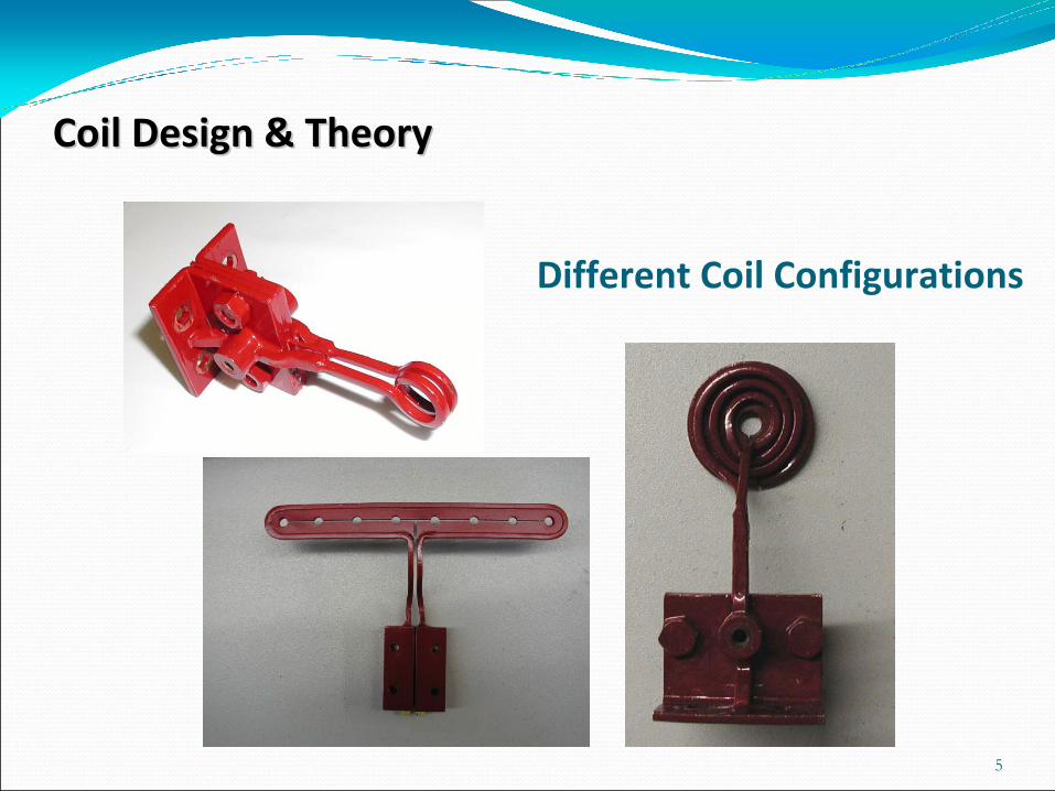
Different Coil Configurations
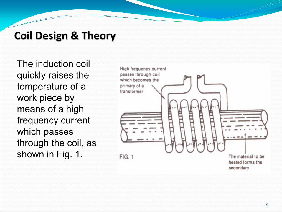
The induction coil quickly raises the temperature of a work piece by means of a high frequency current which passes through the coil, as shown in Fig. 1.
6
Coil Design & TheoryCoil Design & Theory
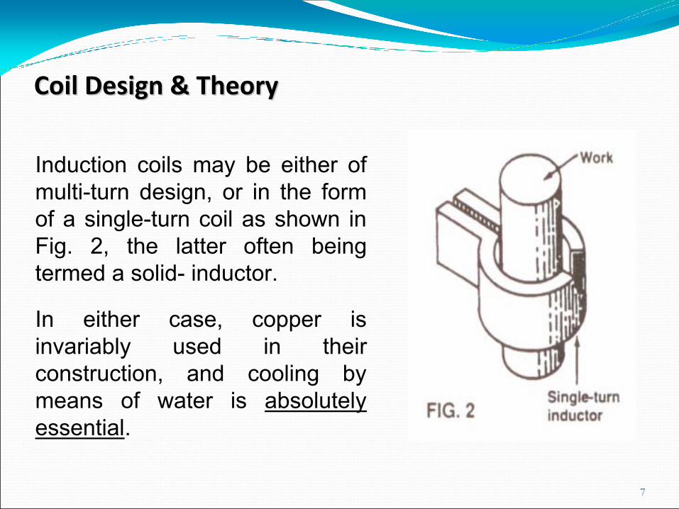
Induction coils may be either of multi-turn design, or in the form of a single-turn coil as shown in Fig. 2, the latter often being termed a solid- inductor.
In either case, copper is invariably used in their construction, and cooling by means of water is absolutely essential.
7
Coil Design & TheoryCoil Design & Theory
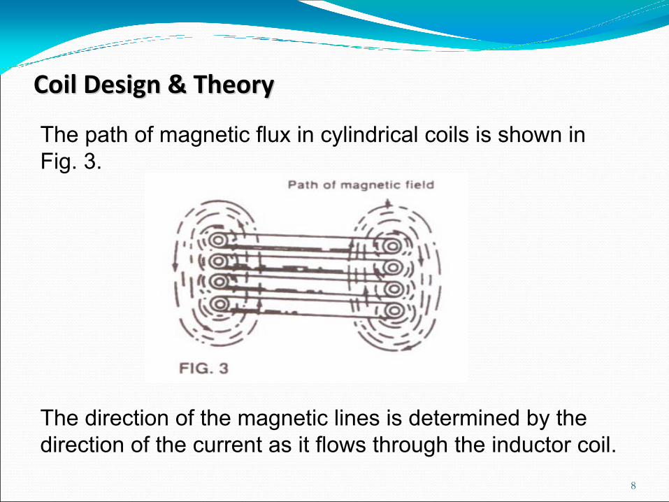
The path of magnetic flux in cylindrical coils is shown in Fig. 3.
The direction of the magnetic lines is determined by the direction of the current as it flows through the inductor coil.
8
Coil Design & TheoryCoil Design & Theory
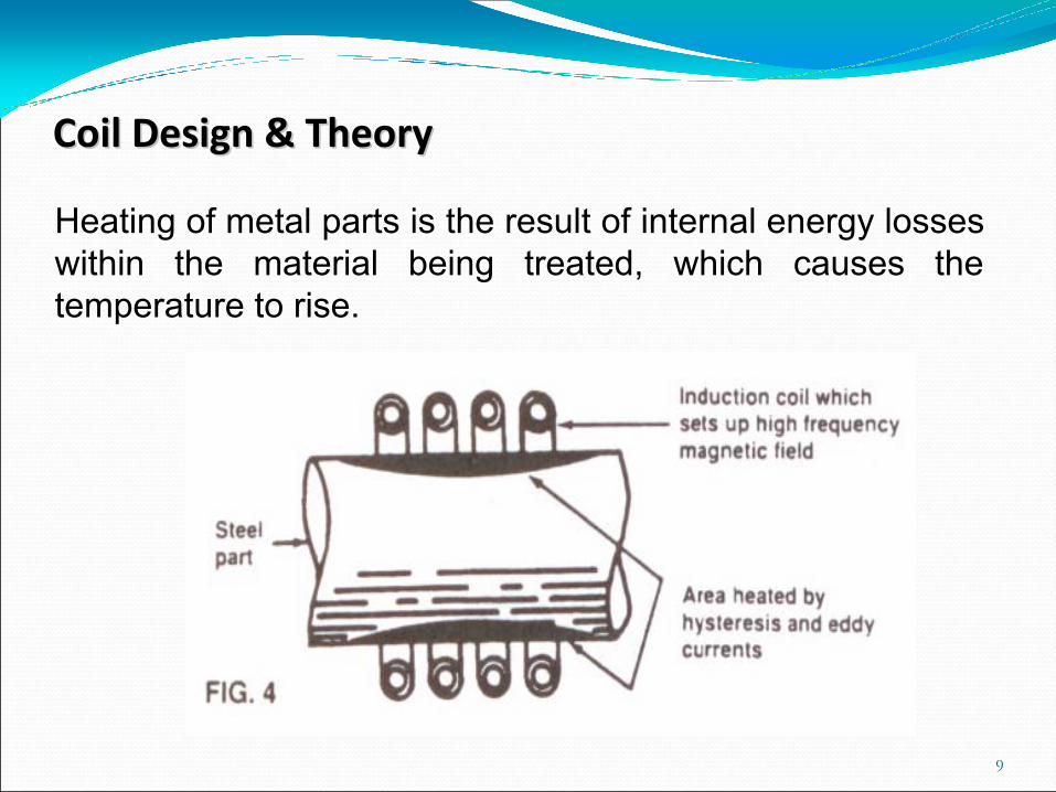
Heating of metal parts is the result of internal energy losses within the material being treated, which causes the temperature to rise.
9
Coil Design & TheoryCoil Design & Theory
•Magnetic fields occur in the area surrounding the coil, and are stronger next to it than at any distance away from it•Placing the work piece close to the coil maximizes theheat energy generated. •The strength of the field varies inversely with the square of the distance between the work and the coil.
• distance between coil and work piece will have a direct relation to the amount of heat generated in a work piece.
10
Coil Design & TheoryCoil Design & Theory
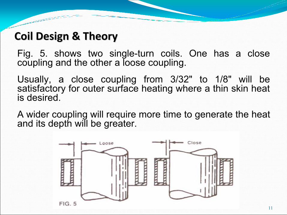
Fig. 5. shows two single-turn coils. One has a close coupling and the other a loose coupling.
Usually, a close coupling from 3/32" to 1/8" will be satisfactory for outer surface heating where a thin skin heat is desired.
A wider coupling will require more time to generate the heat and its depth will be greater.
11
Coil Design & TheoryCoil Design & Theory
When multi-turn coils are closely coupled to a workpiece, there is a tendency for the eddy-currents to create a heat pattern matching the coil’s helix.
The wider the pitch of the coil, the more pronounced this pattern will be.
When the coil is more loosely coupled, that is at a greater distance from the surface to be heated, the stream of eddy currents spreads over a wider area.
12
Coil Design & TheoryCoil Design & Theory
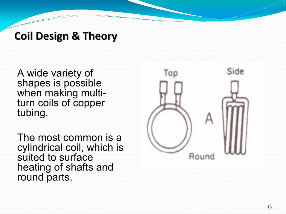
A wide variety of shapes is possible when making multi-turn coils of copper tubing.
The most common is a cylindrical coil, which is suited to surface heating of shafts and round parts.
13
Coil Design & TheoryCoil Design & Theory
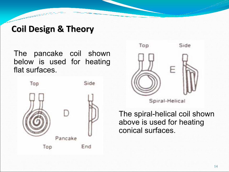
The pancake coil shown below is used for heating flat surfaces.
The spiral-helical coil shown above is used for heating conical surfaces.
14
Coil Design & TheoryCoil Design & Theory
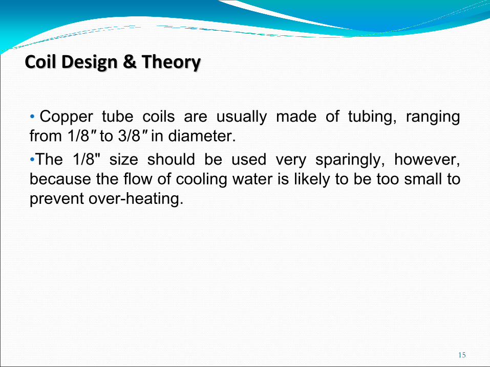
• Copper tube coils are usually made of tubing, ranging from 1/8" to 3/8" in diameter. •The 1/8" size should be used very sparingly, however, because the flow of cooling water is likely to be too small to prevent over-heating.
15
Coil Design & TheoryCoil Design & Theory
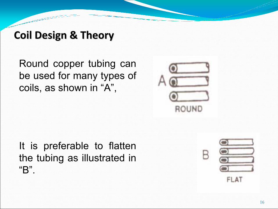
Round copper tubing can be used for many types of coils, as shown in “A”,
It is preferable to flatten the tubing as illustrated in “B”.
16
Coil Design & TheoryCoil Design & Theory
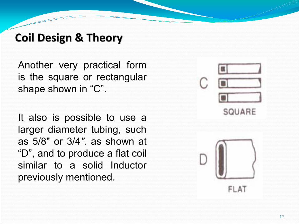
Another very practical form is the square or rectangular shape shown in “C”.
It also is possible to use a larger diameter tubing, such as 5/8" or 3/4". as shown at “D”, and to produce a flat coil similar to a solid Inductor previously mentioned.
17
Coil Design & TheoryCoil Design & Theory
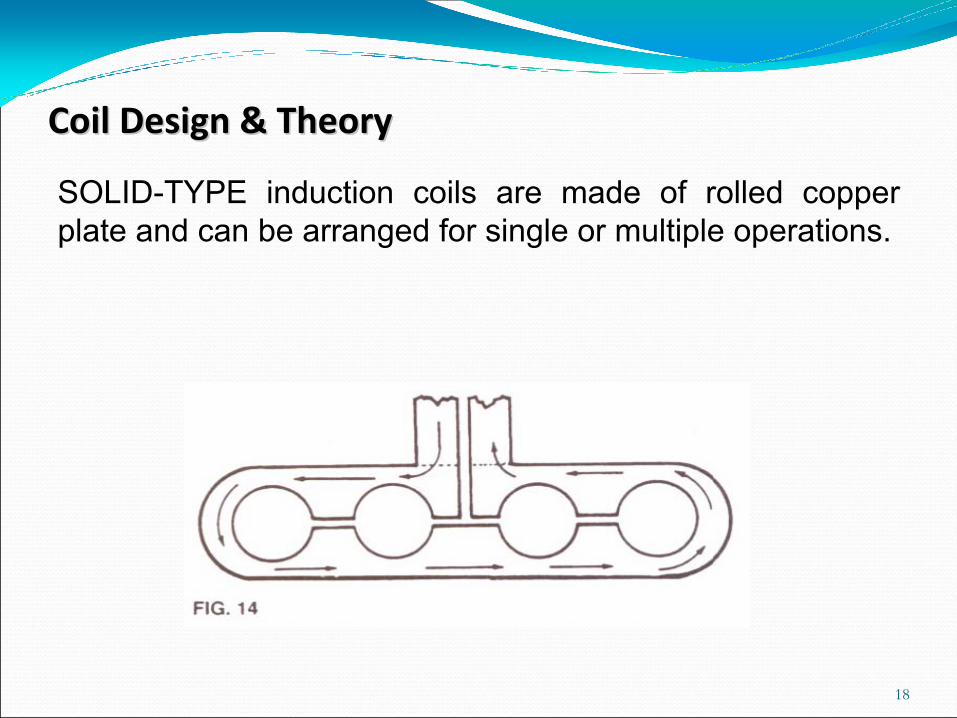
SOLID-TYPE induction coils are made of rolled copper plate and can be arranged for single or multiple operations.
18
Coil Design & TheoryCoil Design & Theory
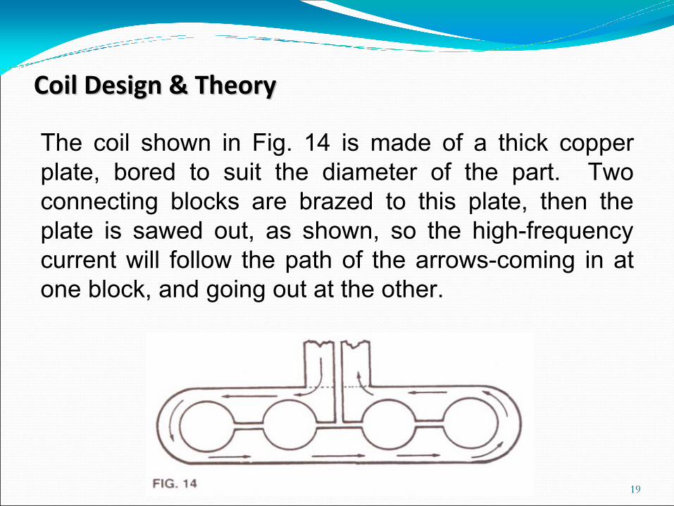
The coil shown in Fig. 14 is made of a thick copper plate, bored to suit the diameter of the part. Two connecting blocks are brazed to this plate, then the plate is sawed out, as shown, so the high-frequency current will follow the path of the arrows-coming in at one block, and going out at the other.
19
Coil Design & TheoryCoil Design & Theory
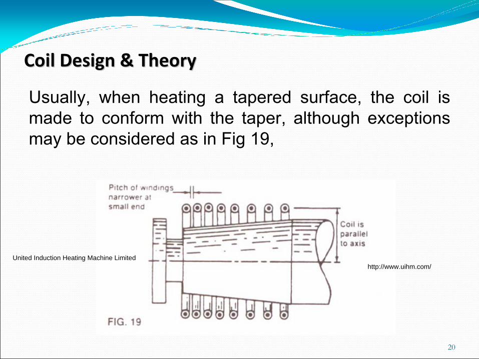
Usually, when heating a tapered surface, the coil is made to conform with the taper, although exceptions may be considered as in Fig 19,
20
Coil Design & TheoryCoil Design & Theory
United Induction Heating Machine Limited http://www.uihm.com/