Embed Size (px)
Citation preview

srl
www.plafondplast.com
I - GB
PVC PIPES FOR GEOTECHNICS

CHARACTERISTICS
Durability: the physical and chemical properties of thePVC used for the production of PLAFOND pipes and thehigh quality of the pipes themselves, guarantees the longlife of the well.
Dielectric strength: PLAFOND pipes are made ofsynthetic materials that are not damaged by stray under-ground currents.
Anti-corrosive properties: PLAFOND pipes are protectedagainst waterbed corrosion, which can often be extremelyaggressive.
Simple jointing: the special male-female threadingpermits rapid, safe jointing without the use of sealantssuch as putty or fillers.
Watertight seal: the seal is guaranteed by specialO-rings on the joints.
Hygiene: PLAFOND pipes and filters are produced inaccordance with the Ministry of Hygiene sanitary re-gulations for drinking water equipment (see enclosedcertificate).
Mechanical strength: PLAFOND’s thicker pipe endsensure perfect mechanical strength in the threaded area.
Simple to use: lightweight with simple joints, the pipesare easy to install and can save greatly on labor costs.
2
The pipes in rigid blue PVC are threaded male-to-femalefor artesian wells for drinking water.The first company in Italy to produce the threading systemon pipes, today PLAFOND PLAST is specialized in theproduction of different sized threaded pipes. The rangeof diameters starts from 4” and reaches a maximumdiameter of 630 mm.The high quality of the raw materials used, and thetechnology of the production systems, ensure the correctfunction of pipes and filters even for very large, deepwells.
THREADED PIPES IN RIGID PVCCOLOR BLUE RAL 5015
Use: ARTESIAN WELLS.

mm Kg / mt Euro / mt Euro / mt
min. 0,3 max 3,0
min. 0,5 max 3,0
min. 0,3 max 3,0
min. 0,3 max 3,0
min. 0,5 max 3,0
min. 0,3 max 3,0
min. 0,5 max 3,0
min. 0,75 max 3,0
min. 0,5 max 3,0
min. 0,3 max 3,0
min. 0,5 max 3,0
min. 0,75 max 3,0
min. 0,3 max 3,0
min. 0,5 max 3,0
min. 0,5 max 3,0
min. 0,5 max 3,0
min. 0,5 max 3,0
min. 0,75 max 3,0
min. 0,5 max 3,0
min. 0,5 max 3,0
min. 0,75 max 3,0
min. 0,5 max 3,0
min. 0,5 max 3,0
min. 0,75 max 3,0
min. 0,5 max 3,0
min. 0,75 max 3,0
min. 0,75 max 3,0
min. 0,75 max 3,0
min. 0,75 max 3,0
min. 0,75 max 3,0
min. 0,75 max 3,0
min. 0,75 max 3,0
min. 0,75 max 3,0
114
114
118
125
125
140
140
140
145
160
160
160
165
165
170
180
180
180
200
200
200
225
225
225
250
250
250
280
280
330
330
400
400
4”
4”
/
4”1/2
4”1/2
5”
5”
5”
/
6”
6”
6”
/
/
/
6”1/2
6”1/2
6”1/2
7”
7”
7”
8”
8”
8”
9”
9”
9”
12”
12”
14”
14”
16”
16”
119
122
122
131
138
145
148
155
152
167
170
178
172
175
180
188
191
201
210
214
224
237
241
252
262
268
280
300
307
353
362
432
437
103
99,4
108
112
106
128
126
119
131,6
147
144
136
152
149
154
165
162
153
184
180
170
207
203
191,6
231
226
214
254
248
300
292
362
357
R8–5,4
R10–7,2
R8–5,0
R10–6,0
R16–9,3
R8–5,4
R10–6,7
R16–10,4
R10–6,7
R8–6,2
R10–7,7
R16–11,9
R8–6,2
R10–7,7
R10–7,7
R8–7,0
R10–8,6
R16–13,4
R8–7,7
R10–9,6
R16–14,9
R8–8,7
R10–10,8
R16–16,7
R8–9,0
R10–11,9
R16–18,0
R8–12,5
R10–16,0
R8–14,5
R10–19,0
R8–19,0
R10–21,5
TPN6
TPN6
TPN6
TPN6
TPN6
TPN6
TPN6
TPN6
TPN6
TPN6
TPN6
TPN6
TPN6
TPN6
TPN6
TPN6
TPN6
TPN6
TPN6
TPN6
TPN6
TPN10
TPN10
TPN10
TPN10
TPN10
TPN10
TPN10
TPN10
TPN10
TPN10
TPN10
TPN10
2,73
3,57
2,62
3,50
5,00
3,38
4,15
6,26
4,30
4,43
5,45
8,20
4,58
5,62
5,80
5,63
6,85
10,37
6,88
8,50
12,81
8,75
10,75
16,17
10,08
13,16
19,40
15,54
19,63
21,26
27,46
33,64
37,80
10,25
13,38
10,00
12,55
19,91
12,91
15,75
24,89
16,34
16,94
20,66
32,49
17,46
21,48
22,21
21,59
26,03
41,21
26,13
32,23
50,92
35,04
42,97
65,07
43,49
52,63
77,73
63,16
79,79
85,94
111,04
134,28
150,95
16,45
20,92
16,20
20,3
27,66
21,17
24,53
33,67
25,10
26,75
30,99
42,81
27,27
31,81
33,05
32,43
37,39
52,58
38,01
44,62
64,35
48,99
57,43
97,61
58,98
69,15
110,52
88,99
105,62
111,76
150,03
173,27
195,36
3/ PRICE LIST F/09/08
PIPES WITH TRAPEZOID MALE-FEMALE THREADING (DIN 4925)
External Diameter
External mm Inches Spigot mm Internal mm. Thread Cutting thickness mm
External Diam. Diameter Thickness Type Weight Slotting Pipe Filter
Standard bar length 5 m (other lengths on request) / Slotting: slots of 0.3 – 0.5 – 0.75 – 1.0 – 1.5 – 2.0 – 2.5 – 3.0 mm
Rigid PVC 100 pipes according to the requirements of the Italian Ministry of Health (M.D. no. 174 of 06/04/2004).

4
mm Kg / mt
min. 0,3 max 3,0
min. 0,3 max 3,0
min. 0,3 max 3,0
min. 0,5 max 3,0
min. 0,5 max 3,0
min. 0,3 max 3,0
min. 0,5 max 3,0
min. 0,5 max 3,0
min. 0,3 max 3,0
min. 0,5 max 3,0
min. 0,5 max 3,0
min. 0,5 max 3,0
min. 0,75 max 3,0
min. 0,5 max 3,0
min. 0,75 max 3,0
min. 0,3 max 3,0
min. 0,5 max 3,0
min. 0,5 max 3,0
min. 0,75 max 3,0
min. 0,5 max 3,0
min. 0,5 max 3,0
min. 0,75 max 3,0
125
140
160
160
160
180
180
180
200
200
200
200
200
225
225
250
250
250
250
315
315
315
4”1/2
5”
6”
6”
6”
6”1/2
6”1/2
6”1/2
7”
7”
7”
7”
7”
8”
8”
9”
9”
9”
9”
13”
13”
13”
137
152
172
175,4
178
192
195,4
198
212
215,4
218
219,2
224
242,4
247
262
265,4
268
274
330,4
333
339
113
128
148
144,6
142
168
164,6
162
188
184,6
182
180,8
176
207,6
203
238
234,6
232
226
299,6
297
291
3,48
3,90
4,50
5,70
6,60
5,08
6,46
7,49
5,67
7,20
8,37
8,90
10,98
9,16
11,46
7,13
9,08
10,56
13,90
11,52
13,40
17,70
7,53
8,48
9,74
12,36
14,42
11,10
13,99
16,23
12,27
15,61
18,15
19,40
23,90
20,46
25,59
15,46
19,67
23,58
31,10
24,95
30,30
39,72
13,94
15,00
17,85
20,47
24,82
19,96
22,85
27,48
22,00
25,34
30,45
31,73
37,73
32,86
39,42
28,96
33,97
38,38
45,97
41,45
48,51
60,53
6
6
6
7,7
9
6
7,7
9
6
7,7
9
9,6
12
8,7
11
6
7,7
9
12
7,7
9
12
/ PRICE LIST B/09/08
Rigid PVC 100 pipes according to the requirements of the Italian Ministry of Health (M.D. no. 174 of 06/04/2004).
External Diameter
External mm Inches Spigot mm Internal mm. Cutting thickness mm Euro / mt Euro / mt
External Diam. Diameter Thickness Weight Slotting Pipe Filter
PIPES WITH SPIGOT JOINT
Standard bar length 5 m / Slotting: slots of 0.3 – 0.5 – 0.75 – 1.0 – 1.5 – 2.0 – 2.5 – 3.0 mm

5
mm0,30 mm 0,50 - 0,75 mm 1,00 mm 1,50 mm 2,00 mm 3,00 mm
open area m3 / h / m open area m3 / h / m open area m3 / h / m open area m3 / h / m open area m3 / h / m open area m3 / h / m
2”
2”1/2
3”
4”
4”1/2
5”
6”
/
6”1/2
7”
8”
9”
10”
12”
14”
60
75
88
114
125
140
160
170
180
200
225
250
280
330
400
5,00%
5,00%
5,00%
5,00%
5,00%
5,00%
5,00%
5,00%
5,00%
/
/
/
/
/
/
0,80
1,00
1,30
1,60
1,80
2,20
2,30
2,30
2,50
/
/
/
/
/
/
6,00%
6,00%
6,00%
6,00%
6,00%
6,00%
5,50%
5,50%
5,50%
5,00%
5,00%
4,50%
4,50%
/
/
1,00
1,30
1,50
2,00
2,20
2,40
2,70
2,70
2,90
2,90
3,40
3,50
4,00
/
/
8,50%
8,50%
8,50%
8,50%
8,50%
7,50%
7,50%
7,50%
7,50%
7,50%
7,50%
7,00%
7,00%
7,00%
7,00%
1,50
1,80
2,20
2,70
3,00
3,00
3,80
3,80
4,00
4,50
5,00
5,00
5,90
7,00
8,00
9,20%
9,20%
9,20%
9,20%
9,20%
8,00%
8,00%
8,00%
8,00%
8,00%
8,00%
8,00%
8,00%
8,00%
8,00%
1,60
1,90
2,50
3,00
3,30
3,30
4,00
4,50
4,80
5,00
5,50
6,00
6,50
7,80
9,50
11,00%
11,00%
11,00%
11,00%
11,00%
11,00%
11,00%
11,00%
11,00%
11,00%
11,00%
10,00%
10,00%
10,00%
10,00%
2,00
2,30
2,80
3,50
3,80
4,50
5,00
5,50
5,90
6,50
7,50
7,50
8,20
9,50
12,00
12,00%
12,00%
12,00%
12,00%
12,00%
12,00%
12,00%
12,00%
12,00%
12,00%
12,00%
12,00%
12,00%
12,00%
12,00%
2,10
2,50
3,00
4,00
4,50
5,00
6,00
6,50
7,00
7,50
9,00
9,00
10,30
11,50
15,00
/ Cutting thickness
0,3
3 - 4
/ STANDARD SLOTTED SURFACE
0,5
5 - 6
0,75
7 - 8
1,0
8 - 10
1,5
8 - 10
2,0
10 - 12
3,0
12 - 14
External Diameter
Inches
Cutting in mm
% Slotted surface
TECHNICAL SPECIFICATIONS OF PLAFOND FILTERS

6
mm mm Euro / mtmm Euro / mtEuro / mt
1/2”
3/4”
1”
1”1/8
1”1/4
1”1/2
1”1/2
2”
2”
2”1/2
2”1/2
3”
3”
3”
3”1/2
3”1/2
4”
4”
21
26
33,5
38
42
48
48
60
60
75
75
88
88
90
100
100
114
114
3,0
2,6
3,3
3,5
3,7
3,3
4
3,7
4,6
4,2
5,3
4,6
6
5
4,5
5
5,4
7,2
15
20,8
27
31
34,6
41
40
52,6
50,8
66,6
64,4
78,8
76
80
91
90
103
99,4
0,70
0,72
0,88
0,93
0,98
1,03
1,03
1,16
1,16
4,80
4,80
5,00
5,00
5,50
7,50
7,50
9,80
9,80
/
1,13
1,17
1,20
1,21
1,22
1,22
1,26
1,26
2,40
2,40
2,60
2,60
2,60
2,80
2,80
2,90
2,90
/
3,62
4,78
5,42
6,00
5,53
6,35
6,77
7,85
8,78
10,46
10,95
13,48
12,80
13,50
14,40
17,82
22,72
1,68
1,89
2,84
3,49
4,05
3,69
4,42
4,83
5,86
6,60
8,13
8,57
10,85
10,12
9,50
10,40
12,86
16,78
M.M. Gas
M.M. Gas
M.M. Gas
M.M. Gas
M.M. Gas
M.M. Gas–M.F. Gas
M.M. Gas–M.F. Gas–M.F. Trap.
M.M. Gas–M.F. Gas–M.F. Trap.
M.M. Gas–M.F. Gas–M.F. Trap.
M.M. Gas–M.F. Gas–M.F. Trap.
M.M. Gas–M.F. Gas–M.F. Trap.
M.M. Gas–M.F. Gas–M.F. Trap.
M.M. Gas–M.F. Gas–M.F. Trap.
M.F. Trap–sullo spessore
M.F. Trap
M.F. Trap
M.F. Trap
M.F. Trap
/
/
0,3–0,5–1,0 mm.
0,3–0,5–1,0 mm.
0,3–0,5–1,0 mm.
0,3–0,5–1,0 mm.
0,3–0,5–1,0 mm.
0,3–0,5–1,0 mm.
0,3–0,5–1,0 mm.
0,3–0,5–1,0 mm.
0,3–0,5–1,0 mm.
0,3–0,5–1,0 mm.
0,3–0,5–1,0 mm.
0,3–0,5–1,0–1,5 mm.
0,3–0,5–1,0–1,5 mm.
0,3–0,5–1,0–1,5 mm.
0,3–0,5–1,0–1,5 mm.
0,3–0,5–1,0–1,5 mm.
/ PRICE LIST P/09/08
Pipes can be covered with Geotextile, a white, nonwoven fabric in high-tenacitypolypropylene 150g/mq, produced by mechanical needling of fiber webs, withoutthe use of any chemical glues or binders.
Length of standard bars: 3 m or 6 m (other lengths on request).
The line of threaded M.M. pipes are supplied with the joiningsleeve included.
Thread typeFilterPipe Braid Prod
Inches
External Diameter
Cutting thickness Euro / each
Thickness SlottingInt. diam.
Non-toxic according to the requirements of the Italian Ministry of Health (M.D. no. 174 of 06/04/2004).Use: PIEZOMETERS.
THREADED PIPES IN RIGID PVC - COLOR BLUE RAL 5015

7
COSTO - EFFICACIA
QUALITÀ DEL PRODOTTO
FACILITÀ D’IMPIEGO
GARANZIA DI DURATA
PERFETTA TENUTA IDRAULICA
ECONOMICAL - EFFECTIVE
HIGH QUALITY PRODUCTS
EASE OF USE
GUARANTEED DURABILITY
PERFECT WATERTIGHT SEAL
THE ADVANTAGES
STAGES OF WELL CONSTRUCTION
WELL WASHING OPERATIONS

8
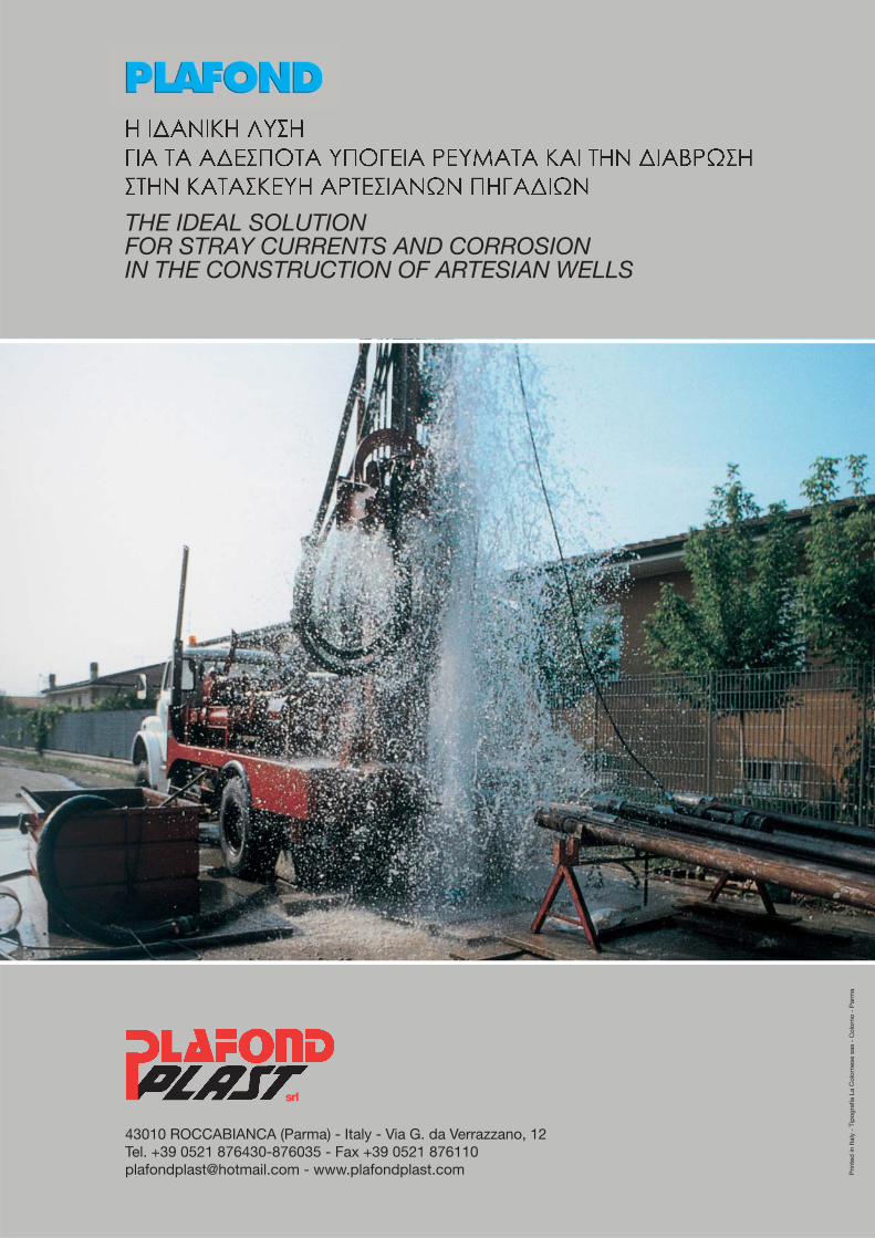
In all situations in which water in the ground is or couldbe the primary cause of damage or destruction of buildingstructures, devices must be used to re-establish thecorrect hydraulic drainage of the soil to prevent risks.PLAFOND sub-horizontal drainage pipes, with a widerange of mechanical and hydraulic features, allow engi-neers to obtain the best performance of the terrain inevery specific case. It is only through careful control andoptimization of the presence of water in every type ofterrain that it will be possible to ensure the maximumcapacity and stability.
RAW MATERIALS
PLAFOND pipes are made of high quality impact-resistantPVC. Modern extrusion technology and the chemical andphysical properties of this polymer give the finishedproduct the following characteristics:• durability• resistance to stray currents in the soil• excellent resistance to chemical aggression by agents
normally present in the soil• good mechanical resistance to crushing• high resistance to impact and falls
MORPHOLOGICAL FEATURES
• Water collection is ensured by the presence along thepipe of narrow slots perpendicular to the axis of thepipe.
• The slots are cut with special equipment that ensuresuniformity and the absence of burrs – a very importantfactor – in order to reduce to a minimum any resistanceto water intake.
• The width of the standard slot -0.4 -0.5 mm – solvesthe problem of water extraction in most types of soilnormally involved in this type of operation. In otherwords, the standard slot dimensions are the bestcompromise, in the range of granulometries of sandysilt and alluvial mixtures, to obtain a good extractioncapacity without the risk of clogging or, on the otherhand, trapping particles inside the pipe. In the presenceof higher granulometries, a higher extraction capacitycan be obtained by increasing the number of slots, upto a maximum of 3. The standard extension of eachslot is 2/9 of the circumference.
FILTERING COVER
To eliminate the risk of clogging by fine sediment carriedby the water, or of trapping, the PLAFOND pipe can becovered on the outside with a geotextile sheath stitchedwith double crossed weft and apply so as to fit tightlyand prevent rolling up during installation of the pipe.The nonwoven fabric used is made of continuous filamentpolypropylene; with its particular features of permeability,it allows water to penetrate, while trapping any particlesthat could enter the pipe and reduce its drainage capacity.
MICROSLOTTED PIPES IN PVC FORDRAINAGE AND CONSOLIDATION
9/ PRICE LIST D/09/08
mm mm Euro / mtmm Euro / mtEuro / mt
1”1/2
1”1/2
2”
2”
2”1/2
2”1/2
3”
3”
3”1/2
3”1/2
4”
4”
48
48
60
60
75
75
88
88
100
100
114
114
3,3
4
3,7
4,6
4,2
5,3
4,6
6
4,5
5
5,4
7,2
41
40
52,6
50,8
66,6
64,4
78,8
76
91
90
103
99,4
1,03
1,03
1,16
1,16
4,80
4,80
5,00
5,00
7,50
7,50
9,80
9,80
1,22
1,22
1,26
1,26
2,40
2,40
2,60
2,60
2,80
2,80
2,90
2,90
5,53
6,35
6,77
7,85
8,78
10,46
10,95
13,48
13,50
14,40
17,82
22,72
3,69
4,42
4,83
5,86
6,60
8,13
8,57
10,85
9,50
10,40
12,86
16,78
M.M. Gas–M.F. Gas
M.M. Gas–M.F. Gas–M.F. Trap.
M.M. Gas–M.F. Gas–M.F. Trap.
M.M. Gas–M.F. Gas–M.F. Trap.
M.M. Gas–M.F. Gas–M.F. Trap.
M.M. Gas–M.F. Gas–M.F. Trap.
M.M. Gas–M.F. Gas–M.F. Trap.
M.M. Gas–M.F. Gas–M.F. Trap.
M.F. Trap
M.F. Trap
M.F. Trap
M.F. Trap
0,3–0,5–1,0 mm.
0,3–0,5–1,0 mm.
0,3–0,5–1,0 mm.
0,3–0,5–1,0 mm.
0,3–0,5–1,0 mm.
0,3–0,5–1,0 mm.
0,3–0,5–1,0 mm.
0,3–0,5–1,0 mm.
0,3–0,5–1,0–1,5 mm.
0,3–0,5–1,0–1,5 mm.
0,3–0,5–1,0–1,5 mm.
0,3–0,5–1,0–1,5 mm.
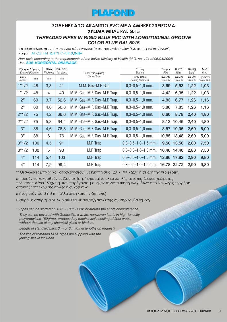
** Pipes can be slotted on 120° - 180° - 220° or around the entire circumference.
They can be covered with Geotextile, a white, nonwoven fabric in high-tenacitypolypropylene 150g/mq, produced by mechanical needling of fiber webs,without the use of any chemical glues or binders.
Length of standard bars: 3 m or 6 m (other lengths on request).
The line of threaded M.M. pipes are supplied with thejoining sleeve included.
Thread typeFilterPipe Braid Prod
Inches
External Diameter
Cutting thickness Euro / each
Thickness SlottingInt. diam.
THREADED PIPES IN RIGID BLUE PVC WITH LONGITUDINAL GROOVECOLOR BLUE RAL 5015
Non-toxic according to the requirements of the Italian Ministry of Health (M.D. no. 174 of 06/04/2004).Use: SUB-HORIZONTAL DRAINAGE.

10
Produced in PVC, and therefore lightweight and mana-geable, the valved PLAFOND pipe is a reliable, economicsolution for injection needs using cement mortar or otherblends.
CHARACTERISTICS AND ACCESSORIESThe thickness of the pipe makes it able to withstandinternal pressures from 60 to 120 bar.The bars, in standard lengths of 6 meters, are threadedon both ends and the joint is covered with a sturdy sleeve.The rubber valves are fastened to the pipe through twolocking rings in PVC, welded to the pipe so as to resistfriction stresses.The driving operations can be facilitated by threadedconical plugs.The interaxes available between the valves make it possibleto install from 1 to 4 on every meter of pipe.
EXAMPLES OF USEPreliminary injections: in underground works (tunnelsand wells), they ensure the maximum reliability and safetywhen crossing unstable zones and/or zones with a highwater content.
Injections for waterproofing: generally used in damconstruction. They improve the seal of the bottom of theholding dam and serve to construct sections designedto reduce leakage around the base of the reinforcementsagainst the risks of pressure, elevation or trapping.
Injections for consolidation: with multiple applicationsin fractured soil. For the reconstruction of a monolithicmass in the decompressed rock surrounding a tunnel.To ensure a solid base for heavy foundations. To restoreworks of art with deteriorated walls.
Injections of adhesive (or binder): used to make theworks adhere perfectly to the rocky underbase, eliminatingthe risk of slippage. Or to fill gaps between the lining ofa tunnel and its rock profile.
Filler injections: generally performed between the rockand the tunnel lining. They fill the gaps caused by juttingelements, preventing contact with water and permittingcorrect division of pressures so as to prevent the risk ofperforation by the jutting rocks.
VALVED PIPE IN RIGID BLUE PVC FORINJECTIONS OF CONSOLIDATION

11
/ PRICE LISTV/09/08
mm
mm Euro / mt
21
34
38
38
48
48
48
48
60
60
60
60
15
27
31
28
41
40
38
35
53
52
50
41
3,0
3,5
3,5
5,0
3,5
4,0
5,0
6,5
3,5
4,0
5,0
9,5
3–6
3–6
3–6
3–6
3–6
3–6
3–6
3–6
3–6
3–6
3–6
3–6
0,70
0,88
0,93
0,93
1,03
1,03
1,03
1,03
1,16
1,16
1,16
1,16
1,60
2,01
2,17
2,17
2,43
2,43
2,43
2,43
2,80
2,80
2,80
2,80
1,70
2,84
3,49
4,77
3,95
4,48
5,45
7,18
4,56
5,20
6,37
11,00
25
38
43
43
53
53
53
53
65
65
65
65
M.M. Gas
M.M. Gas–M.M. Trap P 4
M.M. Gas–M.M. Trap P 4
M.M. Gas–M.M. Trap P 4
M.M. Gas–M.M. Trap P 4
M.M. Gas–M.M. Trap P 4
M.M. Gas–M.M. Trap P 4
M.M. Gas–M.M. Trap P 4
M.M. Gas–M.M. Trap P 4
M.M. Gas–M.M. Trap P 4
M.M. Gas–M.M. Trap P 4
M.M. Gas–M.M. Trap P 4
250–330–500–1000 mm
250–330–500–1000 mm
250–330–500–1000 mm
250–330–500–1000 mm
250–330–500–1000 mm
250–330–500–1000 mm
250–330–500–1000 mm
250–330–500–1000 mm
250–330–500–1000 mm
250–330–500–1000 mm
250–330–500–1000 mm
250–330–500–1000 mm
2,00
2,79
2,79
2,79
3,36
3,36
3,36
3,36
3,67
3,67
3,67
3,67
21
34
38
38
15
27
31
28
3,0
3,5
3,5
5,0
a misura
a misura
a misura
a misura
0,70
0,88
0,93
0,93
1,60
2,01
2,17
2,17
1,87
3,12
3,84
5,25
25
38
43
43
M.M. Gas
M.M. Gas–M.M. Trap P 4
M.M. Gas–M.M. Trap P 4
M.M. Gas–M.M. Trap P 4
250–330–500–1000 mm
250–330–500–1000 mm
250–330–500–1000 mm
250–330–500–1000 mm
/
/
/
/
/ Use: TIE RODS.
THREADED PIPES IN RIGID PVC - COLOR BLUE RAL 5015WITH VALVES
Non-toxic according to the requirements of the Italian Ministry of Health (M.D. no. 174 of 06/04/2004).Use: CEMENT INJECTIONS.
Thread typePipeDimensions Valve Prod
Outside
Diameter mm
Hose type Euro / each Euro / each
Thickness Valve pitch
Bars mt
Length
Inside Valve mm
Sleeve
Euro / each
Euro / mtThread type
PipeDimensions Valve Prod
Outside
Diameter mm
Hose type Euro / each Euro / each
Thickness Valve pitch
Bars mt
Length
Inside Valve mm
Sleeve
Euro / each

12

13
FONDAZIONE LABORATORIO PROVE MATERIE PLASTICHE
Dip. Chimica, Materiali e Ingegneria Chimica “Giulio Natta”
POLITECNICO DI MILANO - P.zza L. da Vinci, 32 - 20133
P. I.V.A. 10976540152Tel. 0039-02-706.30.879 - Fax 0039-02-2399.3266
E-mail: [email protected] Web: www.polimi.it/ciic/fondazione
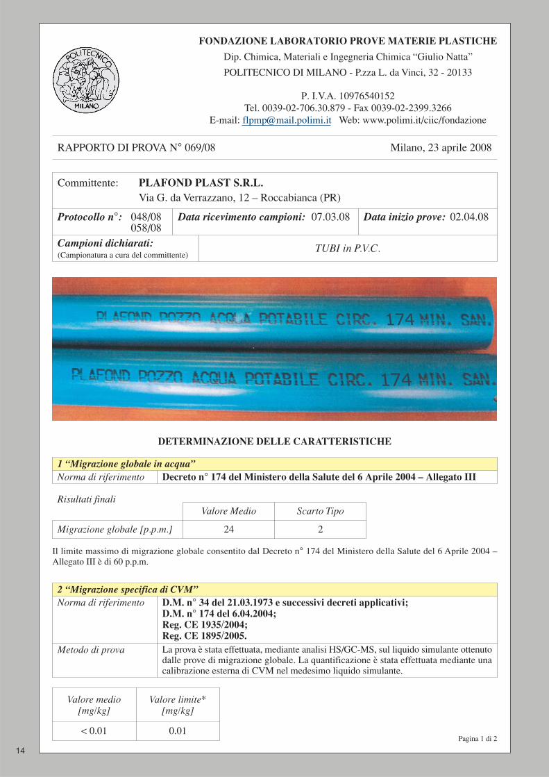
RAPPORTO DI PROVA N° 069/08 Milano, 23 aprile 2008
Committente: PLAFOND PLAST S.R.L.Via G. da Verrazzano, 12 – Roccabianca (PR)
Protocollo n°: 048/08058/08
Data ricevimento campioni: 07.03.08 Data inizio prove: 02.04.08
Campioni dichiarati:(Campionatura a cura del committente)
TUBI in P.V.C.
1 “Migrazione globale in acqua”Norma di riferimento Decreto n° 174 del Ministero della Salute del 6 Aprile 2004 – Allegato III
Risultati finaliValore Medio Scarto Tipo
Migrazione globale [p.p.m.] 24 2
Il limite massimo di migrazione globale consentito dal Decreto n° 174 del Ministero della Salute del 6 Aprile 2004 –Allegato III è di 60 p.p.m.
2 “Migrazione specifica di CVM”Norma di riferimento D.M. n° 34 del 21.03.1973 e successivi decreti applicativi;
D.M. n° 174 del 6.04.2004;Reg. CE 1935/2004;Reg. CE 1895/2005.
Metodo di prova La prova è stata effettuata, mediante analisi HS/GC-MS, sul liquido simulante ottenutodalle prove di migrazione globale. La quantificazione è stata effettuata mediante unacalibrazione esterna di CVM nel medesimo liquido simulante.
< 0.01 0.01
Valore medio[mg/kg]
Valore limite*[mg/kg]
14
DETERMINAZIONE DELLE CARATTERISTICHE
Pagina 1 di 2

RAPPORTO DI PROVA N° 069/08 Milano, 23 aprile 2008
Dirigente TecnicoP.I. Gabriele Depinto
Direttore ScientificoProf. Andrea Pavan
3 “Migrazione di coloranti”Norma di riferimento D.M. n° 34 del 21.03.1973 e successivi decreti applicativi;
D.M. n° 174 del 6.04.2004;Reg. CE 1935/2004;Reg. CE 1895/2005.
Metodo di prova La prova è stata effettuata, mediante esame spettrofotometrico tra 400 e750 nm eseguito con il liquido simulante ottenuto dalle prove di cessione.
< 95 95
Valore medioTrasmittanza [%]
Valore minimo*Trasmittanza [%]
4 “Test sensoriale gustativo – metodo F”Norma di riferimento D.M. n° 34 del 21.03.1973 e successivi decreti applicativi;
D.M. n° 174 del 6.04.2004;Reg. CE 1935/2004;Reg. CE 1895/2005.
Condizionamento 2 ore a 40 ± 1°CN° assaggiatori 8Q.tà di campione 20 gLiquido simulante 1000 ml di acqua minerale naturale
L’esame gustativo consiste in una valutazione della differenza di sapore tra un campione di acqua incontaminata(“bianco”) e un campione di acqua rimasta a diretto contatto con il campione da esaminare.La scala di misura è così definita:
0 nessun sapore percepibile1 sapore appena percepibile ma non definibile2 sapore debole ma non definibile3 sapore netto4 sapore molto netto.
Il risultato finale è espresso come media aritmetica dei punteggi espressi dai diversi assaggiatori, arrotondando ilvalore alla prima cifra decimale ad accompagnandolo con lo scarto tipo.Al campione viene riconosciuto un potenziale impatto organolettico sul prodotto se il punteggio medio è >_ 3.
Risultati finali
0.0 1.8
Bianco Valoremedio
1.0
Scartotipo
15
Pagina 2 di 2
* I diversi valori limite sono indicati nei D.M. n° 174 del 6.04.2004, D.M. n° 34 del 21.03.1973 e successiviaggiornamenti e in varie direttive europee.
Le determinazioni sono state effettuate presso un laboratorio accreditato Sinal.
srl
Prin
ted
in It
aly
- Ti
pog
rafia
La
Col
orne
se s
as -
Col
orno
- P
arm
a
43010 ROCCABIANCA (Parma) - Italy - Via G. da Verrazzano, 12Tel. +39 0521 876430-876035 - Fax +39 0521 [email protected] - www.plafondplast.com
THE IDEAL SOLUTIONFOR STRAY CURRENTS AND CORROSIONIN THE CONSTRUCTION OF ARTESIAN WELLS


![Geotechnics - C1 [Compatibility Mode]](https://img.dokumen.tips/doc/110x75/577d1d351a28ab4e1e8bd247/geotechnics-c1-compatibility-mode.jpg)