Embed Size (px)
Citation preview

The right way to attach almost anything to metal roofs!
888-
825-
3432
w
ww
.S-5
.com
PV
Kit
2.0
Inst
alla
tion
Inst
ruct
ions
Installation InstructionsS-5!® Warning! Please use these products responsibly! Visit our website or contact your S-5! distributor for available load test results. The user and/or the installer of these parts is responsible for all necessary engineering and design for the intended use of these parts in an assembly or application. Note that a continuous ground must be followed in accordance with National Electric Code (NEC), ANSI/NFPA 70. Installation in Canada must be in accordance with CSA C22.1, Safety Standard for Electrical Installations, Canadian Electrical Code, Part 1. For UL 2703 Listed assemblies (listing pending) use with PV Modules having a maximum fuse rating of 25A or less. Prior to installation, contact the local code Authority Having Jurisdiction (AHJ) to determine the proper grounding requirements. Visit www.S-5.com for more details.
Tools Needed• Screw Gun • 3/16” Hex Bit Tip
(provided)
• Calibrated Dial Torque Wrench
1. Install the first row of S-5! clamps, at the edge of the array: It is critical that this row is straight. Install a clamp at both ends of the row, by measuring from a reference point such as the eave of the roof. Tighten the setscrews with Screw Gun and the included Hex Bit Tip. The setscrews will dimple the seam material but will not penetrate it. When relying on published load values, setscrew tension should be verified periodically using a calibrated torque wrench to ensure the tool is consistently achieving the proper torque range (see Setscrew Torque Table below). Please see installation instructions provided with clamps for specifics. Stretch a string line between the two end clamps to provide a true line to mount the remaining edge clamps (Fig. 1).
To install PV Kit 2.0 On Standing Seam
Parts
2. Mount the PV Disks and the EdgeGrab/StandOff Assembly to the first row of clamps: place the PV Disk atop the clamp and thread the Male Portion of the StandOff through the disk and into the clamp. Drive the EdgeGrab/StandOff Assembly down with provided Hex Bit Tip (Fig. 2) until the base of the StandOff seats the disk in place and breaks the thread locking seal between the StandOff and Low Profile Bolt. Leave the grab up, to allow space for a module frame. A 1/2” open end wrench can be used to further tighten the StandOff atop the disk if desired.
PV Disk
StandOff
EdgeGrab/StandOff Assembly MidGrab/StandOff Assembly
Wire Management Tie Off Holes
Module Placement Bevel GuideBonding Teeth
Male Portioncutaway for 1/2” wrench option
EdgeGrab
Low Profile Bolt
Accessory Slot
3/16” Hex Drive
3/16” Hex Drive
Thread locking compound
1.
2.
MidGrab
StandOff
Low Profile Bolt
S-5! Clamp Setscrew Torque Table (torque varies depending on roof material)

3. Install the first row of modules (Fig 3a): Place first module in the grabs pushing on the frame to seat the module against the EdgeGrabs and Module Placement Bevel Guide (Fig 3b). Drive the Low Profile Bolt with the provided hex bit to tighten the grabs (Fig 3c). Low Profile Bolt and Standoff should be torqued to 120-130 in lbs (13.6-14.7 Nm). Check torque periodically with Calibrated Dial Torque Wrench.
Note: PV Kit 2.0 fitsmodule frame thicknesses from33 mm-46 mm
4. Install MidGrab/StandOff Assembly & PV Disk on Clamps: the PV Disk and MidGrab/StandOff Assembly should be mounted to the clamps before mounting the clamps to the roof. Place the PV Disk atop the clamp and thread the male portion of the StandOff through the disk and into the clamp. Drive the MidGrab/StandOff Assembly down with the provided bit tip (Fig 4) in similar fashion to Step 2. Note: When using the S-5-H90 or S-5-K Grip style clamps, the clamp must be secured to the roof prior to fixing the S-5-PV Kit 2.0 EdgeGrab or MidGrab assembly to clamps. See: Tips for Mounting with CorruBrackets, S-5-H90, or S-5 K Grip Style Clamps at end of installation instructions.
5. Place MidGrab/StandOff/Disk & Clamp Assemblies: using the PV module as a guide, place the throat of the clamp over the seam and slide the assembly into place so that the edge of the module is seated against the wall of the MidGrab and the Module Placement Bevel Guide, similar to (Fig 3b). Tighten the setscrew(s) of the clamp as described in step 1. The grabs should be left in the partially open position to accommodate the next row of modules before final tightening.
6. Install Additional PV Modules-repeating steps 3-5: place another module in the MidGrabs that were left open in the previous step. Tighten the downslope row of grabs each time a module is placed and leave the upslope open until the next module is placed (Fig. 6). The final row will be finished with EdgeGrab/StandOff Assemblies. Periodically look back at the modules you’ve installed to double check that the MidGrabs were tightened.
PV Kit 2.0 Installation Instructions
S-5!® Warning! Please use this product responsibly!Products are protected by multiple U.S. and foreign patents. For published data regarding holding strength, fastener torque, patents, and trademarks, visit the S-5! website at www. S-5.com.Copyright 2018, Metal Roof Innovations, Ltd. S-5! products are patent protected. S-5! aggressively protects its patents, trademarks, and copyrights.
3a.
4.
5.
6.
3b. 3c.
The right way to attach almost anything to metal roofs!
888-
825-
3432
w
ww
.S-5
.com
PV
Kit
2.0
Inst
alla
tion
Inst
ruct
ions
These instructions are for use by those experienced in the trade. Always follow appropriate safety precautions and use appropriate tools.
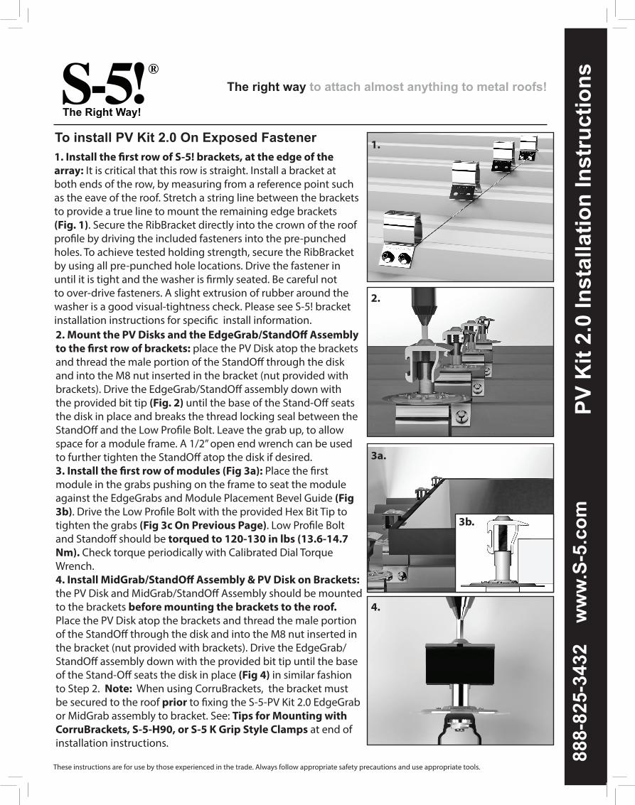
1. Install the first row of S-5! brackets, at the edge of the array: It is critical that this row is straight. Install a bracket at both ends of the row, by measuring from a reference point such as the eave of the roof. Stretch a string line between the brackets to provide a true line to mount the remaining edge brackets (Fig. 1). Secure the RibBracket directly into the crown of the roof profile by driving the included fasteners into the pre-punched holes. To achieve tested holding strength, secure the RibBracket by using all pre-punched hole locations. Drive the fastener in until it is tight and the washer is firmly seated. Be careful not to over-drive fasteners. A slight extrusion of rubber around the washer is a good visual-tightness check. Please see S-5! bracket installation instructions for specific install information.
To install PV Kit 2.0 On Exposed Fastener
2. Mount the PV Disks and the EdgeGrab/StandOff Assembly to the first row of brackets: place the PV Disk atop the brackets and thread the male portion of the StandOff through the disk and into the M8 nut inserted in the bracket (nut provided with brackets). Drive the EdgeGrab/StandOff assembly down with the provided bit tip (Fig. 2) until the base of the Stand-Off seats the disk in place and breaks the thread locking seal between the StandOff and the Low Profile Bolt. Leave the grab up, to allow space for a module frame. A 1/2” open end wrench can be used to further tighten the StandOff atop the disk if desired.3. Install the first row of modules (Fig 3a): Place the first module in the grabs pushing on the frame to seat the module against the EdgeGrabs and Module Placement Bevel Guide (Fig 3b). Drive the Low Profile Bolt with the provided Hex Bit Tip to tighten the grabs (Fig 3c On Previous Page). Low Profile Bolt and Standoff should be torqued to 120-130 in lbs (13.6-14.7 Nm). Check torque periodically with Calibrated Dial Torque Wrench.4. Install MidGrab/StandOff Assembly & PV Disk on Brackets: the PV Disk and MidGrab/StandOff Assembly should be mounted to the brackets before mounting the brackets to the roof. Place the PV Disk atop the brackets and thread the male portion of the StandOff through the disk and into the M8 nut inserted in the bracket (nut provided with brackets). Drive the EdgeGrab/StandOff assembly down with the provided bit tip until the base of the Stand-Off seats the disk in place (Fig 4) in similar fashion to Step 2. Note: When using CorruBrackets, the bracket must be secured to the roof prior to fixing the S-5-PV Kit 2.0 EdgeGrab or MidGrab assembly to bracket. See: Tips for Mounting with CorruBrackets, S-5-H90, or S-5 K Grip Style Clamps at end of installation instructions.
1.
2.
3a.
4.
3b.

5. Place MidGrab/StandOff/Disk & Bracket Assemblies: Using the PV module as a guide, place the bracket on the rib and move into place so that the edge of the module is seated against the wall of the MidGrab and the Module Placement Bevel Guide (Fig. 3b). Secure the RibBracket directly into the crown of the roof profile by driving the fasteners (included with RibBrackets) into the pre-punched holes as described in step 1 above. At this point the grabs should be left in the open position, at least partially to accommodate the next row of modules. 6. Install Additional PV Modules-repeating steps 3-5: place another module in the MidGrabs that were left open in the previous step. Tighten the downslope row of grabs each time a module is placed and leave the upslope MidGrabs open until the next module is placed (Fig. 6). The final row will be finished with EdgeGrab/StandOff Assemblies. Periodically look back at the modules you’ve installed to double check that the MidGrabs were tightened.
PV Kit 2.0 Installation Instructions
S-5!® Warning! Please use this product responsibly!Products are protected by multiple U.S. and foreign patents. For published data regarding holding strength, fastener torque, patents, and trademarks, visit the S-5! website at www. S-5.com.Copyright 2018, Metal Roof Innovations, Ltd. S-5! products are patent protected. S-5! aggressively protects its patents, trademarks, and copyrights. PV20-V1.1-01/18
5.
6.
Wire Management and Bonding and GroundingUL Listed PV wire clips should be used to attach excess wire to the underside of module frames. Clip the wires to the frame before installing the module, so that the leads are positioned correctly. Clips should be placed often enough so that the wire cannot sag and touch the roof. The home run and any other exposed wire should be encased and routed through conduit. The conduit should be intermittently attached to the roof with S-5 clamps or brackets. Module frames within each column are bonded and have an established ground path through the PV Disk. Adjacent columns of modules should be bonded together with a jumper; a UL listed grounding lug should be attached to a module frame at the edge of the array to attach a ground wire for the array.
Tips for Mounting with CorruBrackets, S-5-H90/H90 Mini, S-5-K Grip/K grip Mini When mounting with any S-5! CorruBracket, S-5-H90, S-5-K Grip style clamps, steps 4/5 will vary slightly. The fasteners for clamp or bracket to the roof must be installed before the PV Disk is mounted atop the clamp/bracket. The module can still be used as a spacer to place the clamps/brackets. Prepare a clamp or bracket with the full MidGrab/StandOff Assembly & PV Disk mounted atop it. Place this assembly so that the inside of the midgrab and the Module Placement Bevel Guide on the PV Disk rest against the edge of the module seating it in place as described in step 5 and shown in Fig 3b. Use a marker (do not use graphite pencil) to mark the location of the clamp or bracket on the roof. Now remove the pre-assembled clamp/bracket and PV Kit 2.0 and mount a clamp or bracket without the PV Kit, on the mark you made. After fastening the clamp or bracket in place, the MidGrab/StandOff Assembly & PV Disk can be mounted atop it. The slotted hole atop the bracket allows the kit to be slid out of the way as the module is placed, then pushed into place against the edge of the module and tightened.