Embed Size (px)
Citation preview

1 INTRODUCTION
1
Congratulations on your choice of an AgriMetal Front mount Leaf Blower to complement your operation.This equipment has been designed and manufactured to meet the needs of a discerning turf care indus-try.
Safe, efficient and trouble free operation of your AgriMetal Leaf Blower requires that you and anyone elsewho will be operating or maintaining the machine, read and understand the Safety, Operation, Mainte-nance and Trouble Shooting information contained within the Operator's Manual.
This manual covers the Models BWF 180 JD, BWF 180 Toro and BWF 180 Kubota Front mount LeafBlower. Use the Table of Contents or Index as a guide to locate required information.
Keep this manual handy for frequent reference and to pass on to new operators or owners. Call yourAgriMetal Dealer or Distributor if you need assistance, information or additional copies of the manuals.
OPERATOR ORIENTATION - The directions left, right, front and rear, as mentioned throughout thismanual, are as seen from behind the tractor driver's seat and facing in the direction of travel.

2 SAFETYSAFETY ALERT SYMBOL
Why is SAFETY important to you?
The Safety Alert symbol identifiesimportant safety messages on theAgriMetal Front mount Leaf Blowerand in the manual. When you seethis symbol, be alert to the possibilityof personal injury or death. Followthe instructions in the safety mes-sage.
This Safety Alert symbol meansATTENTION! BECOME ALERT!YOUR SAFETY IS INVOLVED!
Accidents Disable and KillAccidents CostAccidents Can Be Avoided
3 Big Reasons
WARNING - Indicates a potentially hazard-
DANGER - Indicates an imminently hazardous
CAUTION - Indicates a potentially hazardoussituation that, if not avoided, mayresult in minor or moderate injury.It may also be used to alert againstunsafe practices.
ous situation that, if not avoided,could result in death or seriousinjury, and includes hazards that areexposed when guards are removed.It may also be used to alert againstunsafe practices.
situation that, if not avoided, willresult in death or serious injury.This signal word is to be limited tothe most extreme situations typi-cally for machine componentswhich, for functional purposes,cannot be guarded.
SIGNAL WORDS:
Note the use of the signal words DANGER,WARNING and CAUTION with the safetymessages. The appropriate signal word foreach message has been selected using thefollowing guide-lines:
SI NO LEE INGLES, PIDA AYUDAA AIGUIEN QUE SI LO LEA PARAQUE LE TRADUZCA LASMIDIDAS DE SEGURIDAD.
If you have any questions not answered in this manual or require additional copies or the manual isdamaged, please contact your dealer or AgriMetal Inc., 1006 Rue Principale, Wickham, Quebec, Canada,J0C 1S0. Phone (819) 398-6883 or fax (819) 398-5311.
2

SAFETY
YOU are responsible for the SAFE operation andmaintenance of your AgriMetal Front mount LeafBlower. YOU must ensure that you and anyoneelse who is going to operate, maintain or workaround the Leaf Blower be familiar with theoperating and maintenance procedures andrelated SAFETY information contained in thismanual. This manual will take you step-by-stepthrough your working day and alerts you to allgood safety practices that should be adhered towhile operating the Leaf Blower.
Remember, YOU are the key to safety. Goodsafety practices not only protect you but also thepeople around you. Make these practices aworking part of your safety program. Be certainthat EVERYONE operating this equipment isfamiliar with the recommended operating andmaintenance procedures and follows all the safetyprecautions. Most accidents can be prevented. Donot risk injury or death by ignoring good safetypractices.
• Leaf Blower owners must give operatinginstructions to operators or employees beforeallowing them to operate the machine, and atleast annually thereafter per OSHA (Occupa-tional Safety and Health Administration)regulation 1928.57.
• The most important safety device on thisequipment is a SAFE operator. It is theoperator’s responsibility to read and under-stand ALL Safety and Operating instructionsin the manual and to follow these. Mostaccidents can be avoided.
• A person who has not read and understood alloperating and safety instructions is not quali-fied to operate the machine. An untrainedoperator exposes himself and bystanders topossible serious injury or death.
• Do not modify the equipment in any way.Unauthorized modification may impair thefunction and/or safety and could affect the lifeof the equipment.
• Think SAFETY! Work SAFELY!
1. Read and understand theOperator’s Manual and allsafety signs before operating,maintaining, adjusting orunplugging the Leaf Blower.
2.1 GENERAL SAFETY
2. Have a first-aid kit availablefor use should the needarise and know how to useit.
3. Have a fire extinguisheravailable for use should theneed arise and know how touse it.
4. Do not allow riders.
5. Wear appropriateprotective gear.This list includes butis not limited to:
- A hard hat- Protective shoes
with slip resistantsoles
- Protective glasses or goggles- Heavy gloves- Wet weather gear- Hearing protection- Respirator or filter mask
6. Install and secure all guards before starting.
7. Wear suitable ear protectionfor prolonged exposure toexcessive noise.
8. Place all controls in neutral, stop engine, setpark brake, remove ignition key and wait forall moving parts to stop before servicing,adjusting, repairing or unplugging.
9. Clear the area of people, especially smallchildren, before starting the unit.
10. Review safety related items annually with allpersonnel who will operating or maintainingthe Leaf Blower.
3
4
2.2 EQUIPMENT SAFETY GUIDELINES
1. Safety of the operator and bystanders is oneof the main concerns in designing and devel-oping a machine. However, every year manyaccidents occur which could have beenavoided by a few seconds of thought and amore careful approach to handling equipment.You, the operator, can avoid many accidentsby observing the following precautions in thissection. To avoid personal injury or death,study the following precautions and insistthose working with you, or for you, followthem.
2. In order to provide a better view, certainphotographs or illustrations in this manualmay show an assembly with a safety shieldremoved. However, equipment should neverbe operated in this condition. Keep all shieldsin place. If shield removal becomes neces-sary for repairs, replace the shield prior touse.
3. Replace any safety sign or instruction signthat is not readable or is missing. Location ofsuch safety signs is indicated in this manual.
4. Never use alcoholic beverages or drugs whichcan hinder alertness or coordination whileoperating this equipment. Consult your doctorabout operating this machine while takingprescription medications.
5. Under no circumstances should youngchildren be allowed to work with thisequipment. Do not allow persons tooperate or assemble this unit until theyhave read this manual and have developeda thorough understanding of the safetyprecautions and of how it works. Reviewthe safety instructions with all users annually.
6. This equipment is dangerous to children andpersons unfamiliar with its operation. Theoperator should be a responsible, properlytrained and physically able person familiarwith machinery and trained in this equipment'soperations. If the elderly are assisting withwork, their physical limitations need to berecognized and accommodated.
7. Never exceed the limits of a piece of machin-ery. If its ability to do a job, or to do so safely,is in question - DON'T TRY IT.
8. Do not modify the equipment in any way.Unauthorized modification result in seriousinjury or death and may impair the functionand life of the equipment.
9. In addition to the design and configuration ofthis implement, including Safety Signs andSafety Equipment, hazard control and acci-dent prevention are dependent upon theawareness, concern, prudence, and propertraining of personnel involved in the operation,transport, maintenance, and storage of themachine. Refer also to Safety Messages andoperation instruction in each of the appropri-ate sections of the tow vehicle, engine andmachine Manuals. Pay close attention to theSafety Signs affixed to the tow vehicle and themachine.
2.3 SAFETY TRAINING
1. Safety is a primary concern in the design andmanufacture of our products. Unfortunately,our efforts to provide safe equipment can bewiped out by a single careless act of anoperator or bystander.
2. In addition to the design and configuration ofequipment, hazard control and accidentprevention are dependent upon the aware-ness, concern, prudence and proper trainingof personnel involved in the operation, trans-port, maintenance and storage of this equip-ment.
3. It has been said, "The bestsafety feature is an in-formed, careful operator."We ask you to be that kindof an operator. It is theoperator's responsibility to read and under-stand ALL Safety and Operating instructionsin the manual and to follow these. Accidentscan be avoided.
4. Working with unfamiliar equipment can lead tocareless injuries. Read this manual, and themanual for your tow vehicle, before assemblyor operating, to acquaint yourself with themachines. If this machine is used by anyperson other than yourself, or is loaned orrented, it is the machine owner's responsibilityto make certain that the operator, prior tooperating:
a. Reads and understands the operator'smanuals.
b. Is instructed in safe and proper use.
5. Know your controls and how to stop towvehicle, engine, and machine quickly in anemergency. Read this manual and the oneprovided with your tow vehicle.
6. Train all new personnel and review instruc-tions frequently with existing workers. Becertain only a properly trained and physicallyable person will operate the machinery. Aperson who has not read and understood alloperating and safety instructions is not quali-fied to operate the machine. An untrainedoperator exposes himself and bystanders topossible serious injury or death. If the elderlyare assisting with work, their physical limita-tions need to be recognized and accommo-dated.
2.4 SAFETY SIGNS
1. Keep safety signs clean and legible at alltimes.
2. Replace safety signs that are missing or havebecome illegible.
3. Replaced parts that displayed a safety signshould also display the current sign.
4. Safety signs are available from your author-ized Distributor or Dealer Parts Department orthe factory.
How to Install Safety Signs:
• Be sure that the installation area is clean anddry.
• Be sure temperature is above 50°F (10°C).
• Determine exact position before you removethe backing paper.
• Remove the smallest portion of the splitbacking paper.
• Align the sign over the specified area andcarefully press the small portion with theexposed sticky backing in place.
• Slowly peel back the remaining paper andcarefully smooth the remaining portion of thesign in place.
• Small air pockets can be pierced with a pinand smoothed out using the piece of signbacking paper.
5

6
2.5 PREPARATION
1. Never operate the utilityvehicle and machineuntil you have read and completely under-stand this manual, the utility Vehicle Opera-tor's Manual, and each of the Safety Mes-sages found on the safety signs on the towvehicle and machine.
2. Personalprotectionequipmentincluding hardhat, safetyglasses, safetyshoes, andgloves arerecommendedduring assembly, installation, operation,adjustment, maintaining, repairing, removal,or moving the implement. Do not allow longhair, loose fitting clothing or jewelry to bearound equipment.
3. PROLONGED EXPOSURETO LOUD NOISE MAYCAUSE PERMANENTHEARING LOSS!Push vehicles with or withoutequipment attached canoften be noisy enough tocause permanent, partialhearing loss. We recommend that you wearhearing protection on a full-time basis if thenoise in the Operator's position exceeds80db. Noise over 85db on a long-term basiscan cause severe hearing loss. Noise over90db adjacent to the Operator over a long-term basis may cause permanent, totalhearing loss. NOTE: Hearing loss from loudnoise (from tractors, chain saws, radios, andother such sources close to the ear) is cumu-lative over a lifetime without hope of naturalrecovery.
4. Clear working area ofstones, branches or hiddenobstacles that might behooked or snagged, causinginjury or damage.
5. Operate only in daylight orgood artificial light.
6. Be sure machine is properly mounted, ad-justed and in good operating condition.
7. Ensure that all safety shielding and safetysigns are properly installed and in goodcondition.
7
2.6 OPERATING SAFETY
1. Please remember it is important that you readand heed the safety signs on the Blower.Clean or replace all safety signs if they cannotbe clearly read and understood. They arethere for your safety, as well as the safety ofothers. The safe use of this machine is strictlyup to you, the operator.
2. All things with moving parts are potentiallyhazardous. There is no substitute for acautious, safe-minded operator who recog-nizes potential hazards and follows reason-able safety practices. The manufacturer hasdesigned this Leaf Blower to be used with allits safety equipment properly attached, tominimize the chance of accidents. Study thismanual to make sure you have all safetyequipment attached.
3. If a safety shield or guard is removed for anyreason, it must be replaced before the ma-chine is again operated.
4. When the use of hand tools is required toperform any part of assembly, installation,adjustment, maintaining, repairing, removal,or moving, be sure the tools used are de-signed and recommended by the tool manu-facturer for that specific task.
5. Personal protection equipment includinghearing protection, hard hat, safety glasses,safety shoes, and gloves are recommendedduring assembly, installation, operation,adjustment, maintaining, repairing, removal,or moving. Do not allow long hair, loose fittingclothing, or jewelry to be around moving parts.
6. Always use two people to handle heavy,unwieldy components during assembly,installation, removal or moving.
7. Never place any part of your body where itwould be in danger if movement should occurduring assembly, installation, operation,maintaining, repairing, removal or moving.
8. Never place yourself between the pushvehicle and machine while implement is inoperation.
9. Place all controls in neutral, stop engine, setpark brake, remove ignition key and wait forall moving parts to stop before servicing,adjusting, repairing or unplugging.
10. Use extreme care during travel. Slow downon turns and watch out for bumps.
11. Never use alcoholic beverages or drugs whichcan hinder alertness or coordination whileoperating this equipment. Consult your doctorabout operating this machine while takingprescription medications.
12. Do not allow riders on the machine or pushvehicle at any time. There is no safe place forany riders.
13. Before you operate the machine, check overall pins, bolts, and connections to be sure allare securely in place. Replace any damagedor worn parts immediately.
14. Do not allow anyone who is not familiar withthe safety rules and operation instructions touse this machine.
15. Never allow children to operate or be aroundthis machine.
16. Do not reach into blower openings when theengine is running. Keep others away also.
17. Clear the work area of objects which might bepicked up and snagged or entangled in themachine.
18. Keep hands, feet, hair, jewelry, and clothingaway from all moving and/or rotating parts.
19. Do not direct the air stream toward people,animals or buildings to prevent injury ordamage.
20. Do not place hands, feet or other body partsinto air stream.

2.7 TRANSPORT SAFETY
8
1. Comply with state and local laws governinghighway safety and movement of machineryon public roads.
2. The use of flashing amber lights is acceptablein most localities. However, some localitiesprohibit their use. Local laws should bechecked for all highway lighting and markingrequirements.
3. At all times when driving the utility vehicle andequipment on the road or highway under 20mph (32 kph), use flashing amber warninglights and a slow moving vehicle (SMV)identification emblem. Do not exceed 20 mph(32 kph). Reduce speed on rough roads andsurfaces.
4. Plan your route to avoid heavy traffic.
5. Use a mounting pin with provisions for aretainer. Install the retainer.
6. Do not drink and drive.
7. Be a safe and courteous driver. Always yieldto oncoming traffic in all situations, includingnarrow bridges, intersections, etc. Watch fortraffic when operating near or crossingroadways.
8. Never allow riders on either push vehicle ormachine.
2.8 STORAGE SAFETY
1. Store the unit in an area away from humanactivity.
2. Do not permit children to play on or aroundthe stored machine.
3. Store the unit in a dry, level area. Support theframe with planks if required.
2.9 REFUELLING SAFETY
3. Do not refuel the machinewhile smoking or when nearopen flame or sparks.
4. Fill fuel tank outdoors.
5. Prevent fires by keeping machine clean ofaccumulated trash, grease and debris.
2.10 TIRE SAFETY
1. Failure to follow proper procedures whenmounting a tire on a wheel or rim can producean explosion which may result in seriousinjury or death.
2. Do not attempt to mount a tire unless youhave the proper equipment and experience todo the job.
3. Have a qualified tire dealer or repair serviceperform required tire maintenance.
4. When replacing worn tires, make sure theymeet the original tire specifications. Neverundersize.
1. Handle fuel with care. It is highly flammable.
2. Allow engine to cool for 5 minutes beforerefuelling. Clean up spilled fuel before restart-ing engine.
2.11 MAINTENANCE SAFETY
1. Good maintenance is your responsibility.Poor maintenance is an invitation to trouble.
2. Follow good shop practices.
- Keep servicearea clean anddry.
- Be sure electricaloutlets and toolsare properlygrounded.
- Use adequatelight for the job athand.
3. Make sure there is plenty of ventilation.Never operate an engine in a closed building.The exhaust fumes may cause asphyxiation.
4. Before working on this machine, shut off theengine, set the brakes, and remove theignition keys.
6. Never work under equipment unless it isblocked securely.
7. Always use personal protection devices suchas eye, hand and hearing protectors, whenperforming any service or maintenance work.
8. Where replacement parts are necessary forperiodic maintenance and servicing, genuinefactory replacement parts must be used torestore your equipment to original specifica-tions. The manufacturer will not be responsi-ble for injuries or damages caused by use ofunapproved parts and/or accessories.
9
9. A fire extinguisherand first aid kitshould be keptreadily accessiblewhile performingmaintenance onthis equipment.
10. Periodically tighten all bolts, nuts and screwsand check that all cotter pins are properlyinstalled to ensure unit is in a safe condition.
11. When completing a maintenance or servicefunction, make sure all safety shields anddevices are installed before placing unit inservice.
2.12 BATTERY SAFETY
1. Keep all sparks and flames away from batter-ies, as gas given off by electrolyte is explo-sive.
2. Avoid contact with battery electrolyte: washoff any spilled electrolyte immediately.
3. Wear safety glasses when working nearbatteries.
4. Do not tip batteries more than 45 degrees, toavoid electrolyte loss.
5. To avoid injury from spark or short circuit,disconnect battery ground cable beforeservicing any part of electrical system.

10
2.13 GAS MOTOR SAFETY
BEFORE STARTING ENGINE, READ ANDUNDERSTAND THE OPERATING AND MAIN-TENANCE INSTRUCTIONS THAT CAME WITHYOUR ENGINE.
WARNING: DO NOT1. DO NOT run engine in an enclosed area.
Exhaust gases contain carbon monoxide, anodorless and deadly poison.
2. DO NOT place hands or feet near moving orrotating parts.
3. DO NOT store, spill, or use gasoline near anopen flame, or devices such as a stove,furnace, or water heater which use a pilot lightor devices which can create a spark.
4. DO NOT refuel indoors where area is not wellventilated. Outdoor refuelling is preferred.
5. DO NOT fill fuel tank while engine is running.Allow engine to cool for 5 minutes beforerefuelling. Store fuel in approved safetycontainers.
6. DO NOT remove fuel tank cap while engine isrunning.
7. DO NOT operate engine if gasoline is spilled.Move machine away from the spill and avoidcreating any ignition until the gasoline hasevaporated.
8. DO NOT smoke when filling fuel tank.
9. DO NOT choke carburetor to stop engine.Whenever possible, gradually reduce enginespeed before stopping.
10. DO NOT run engine above rated speeds.This may result in injury.
11. DO NOT tamper with governor springs,governor links or other parts which mayincrease the governed engine speed.
12. DO NOT tamper with the engine speedselected by the original equipment manufac-turer.
13. DO NOT check for spark with spark plug orspark plug wire removed. Use an approvedtester.
14. DO NOT crank engine with spark plug re-
moved. If engine is flooded, place throttle in"FAST" position and crank until engine starts.
15. DO NOT strike flywheel with a hard object ormetal tool as this may cause flywheel toshatter in operation. Use proper tools toservice engine.
16. DO NOT operate engine without a muffler.Inspect periodically and replace, if necessary.If engine is equipped with muffler deflector,inspect periodically and replace, if necessarywith correct deflector.
17. DO NOT operate engine with an accumulationof grass, leaves, dirt or other combustiblematerials in the muffler area.
18. DO NOT use this engine on any forest cov-ered, brush covered, or grass covered unim-proved land unless a spark arrester is in-stalled on the muffler. The arrester must bemaintained in effective working order by theoperator. In the State of California the aboveis required by law (Section 4442 of the Califor-nia Public Resources Code). Other statesmay have similar laws. Federal laws apply onfederal lands.
19. DO NOT touch hot muffler, cylinder or finsbecause contact may cause burns.
20. DO NOT run engine with air cleaner or aircleaner cover removed.
WARNING: DO1. ALWAYS DO remove the wire from the spark
plug when servicing the engine or equipmentTO PREVENT ACCIDENTAL STARTING ordisconnect the negative wire from the batteryterminal.
2. DO keep cylinder fins and governor parts freeof grass and other debris which can affectengine speed.
3. DO examine muffler periodically to be sure itis functioning effectively. A worn or leakingmuffler should be repaired or replaced asnecessary.
4. DO use fresh gasoline. Stale fuel can gumcarburetor and cause leakage.
5. DO check fuel lines and fittings frequently forcracks or leaks. Replace if necessary.
6. DO check air filter periodicly.

EMPLOYEES SIGNATURE EMPLOYERS SIGNATURESIGN-OFF FORM
DATE
11
2.14 SIGN-OFF FORM
AgriMetal follows the general Safety Standards specified by the American Society of Agricultural Engineers(ASAE) and the Occupational Safety and Health Administration (OSHA). Anyone who will be operating and/or maintaining the Front mount Leaf Blower must read and clearly understand ALL Safety, Operating andMaintenance information presented in this manual.
Do not operate or allow anyone else to operate this equipment until such information has been reviewed.Annually review this information before the season start-up.
Make these periodic reviews of SAFETY and OPERATION a standard practice for all of your equipment. Wefeel that an untrained operator is unqualified to operate this machine.
A sign-off sheet is provided for your record keeping to show that all personnel who will be working with theequipment have read and understand the information in the Operator’s Manual and have been instructed inthe operation of the equipment.
12
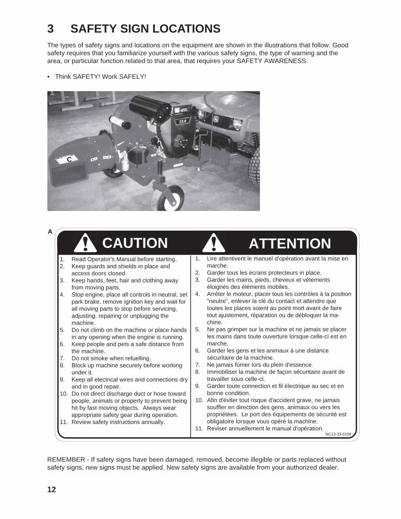
3 SAFETY SIGN LOCATIONSThe types of safety signs and locations on the equipment are shown in the illustrations that follow. Goodsafety requires that you familiarize yourself with the various safety signs, the type of warning and thearea, or particular function related to that area, that requires your SAFETY AWARENESS.
• Think SAFETY! Work SAFELY!
A
REMEMBER - If safety signs have been damaged, removed, become illegible or parts replaced withoutsafety signs, new signs must be applied. New safety signs are available from your authorized dealer.
CAUTION1. Read Operator's Manual before starting.2. Keep guards and shields in place and
access doors closed.3. Keep hands, feet, hair and clothing away
from moving parts.4. Stop engine, place all controls in neutral, set
park brake, remove ignition key and wait forall moving parts to stop before servicing,adjusting, repairing or unplugging themachine.
5. Do not climb on the machine or place handsin any opening when the engine is running.
6. Keep people and pets a safe distance fromthe machine.
7. Do not smoke when refuelling.8. Block up machine securely before working
under it.9. Keep all electrical wires and connections dry
and in good repair.10. Do not direct discharge duct or hose toward
people, animals or property to prevent beinghit by fast moving objects. Always wearappropriate safety gear during operation.
11. Review safety instructions annually.
1. Lire attentivent le manuel d'opération avant la mise enmarche.
2. Garder tous les écrans protecteurs in place.3. Garder les mains, pieds, cheveux et vétements
éloignés des éléments mobiles.4. Arréter le moteur, placer tous les contròles à la position
"neutre", enlever la clé du contact et attendre quetoutes les places soient au point mort avant de fairetout ajustement, réparation ou de débloquer la ma-chine.
5. Ne pas grimper sur la machine et ne jamais se placerles mains dans toute ouverture lorsque celle-ci est enmarche.
6. Garder les gens et les animaux à une distancesécuritaire de la machine.
7. Ne jamais fümer lors du plein d'essence.8. Immobiliser la machine de façon sécuritaire avant de
travailler sous celle-ci.9. Garder toute connection et fil électrique au sec et en
bonne condition.10. Afin d'éviter tout risque d'accident grave, ne jamais
souffler en direction des gens, animaux ou vers lespropriétées. Le port des équipements de sécurité estobligatoire lorsque vous opéré la machine.
11. Reviser annuellement le manual d'opération.
ATTENTION
NC13-33-0108
C
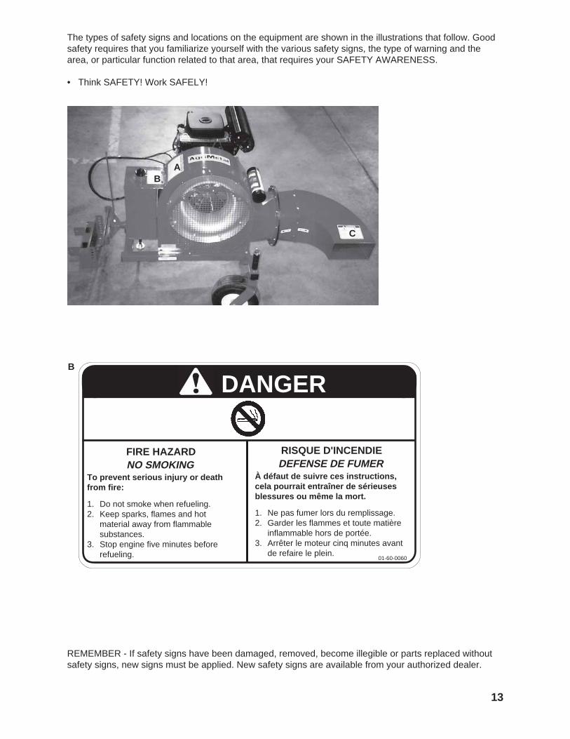
The types of safety signs and locations on the equipment are shown in the illustrations that follow. Goodsafety requires that you familiarize yourself with the various safety signs, the type of warning and thearea, or particular function related to that area, that requires your SAFETY AWARENESS.
• Think SAFETY! Work SAFELY!
13
REMEMBER - If safety signs have been damaged, removed, become illegible or parts replaced withoutsafety signs, new signs must be applied. New safety signs are available from your authorized dealer.
B
FIRE HAZARDNO SMOKING
To prevent serious injury or deathfrom fire:
1. Do not smoke when refueling.2. Keep sparks, flames and hot
material away from flammablesubstances.
3. Stop engine five minutes beforerefueling.
DANGER
RISQUE D'INCENDIEDEFENSE DE FUMER
À défaut de suivre ces instructions,cela pourrait entraîner de sérieusesblessures ou même la mort.
1. Ne pas fumer lors du remplissage.2. Garder les flammes et toute matière
inflammable hors de portée.3. Arrêter le moteur cinq minutes avant
de refaire le plein.01-60-0060
AB
C

The types of safety signs and locations on the equipment are shown in the illustrations that follow. Goodsafety requires that you familiarize yourself with the various safety signs, the type of warning and thearea, or particular function related to that area, that requires your SAFETY AWARENESS.
• Think SAFETY! Work SAFELY!
14
REMEMBER - If safety signs have been damaged, removed, become illegible or parts replaced withoutsafety signs, new signs must be applied. New safety signs are available from your authorized dealer.
C
DANGER
RISQUE D'OBJETS PROJETÉSÁ défaut de suivre ces instructions,cela pourrait entraîner de sérieusesblessures ou même la mort.
1. Arrêter le moteur, placer tous lescontrôles à la position "neutre", enleverla clé du contact et attendre que toutesles places soient au point mort avantde faire tout ajustement, réparation oude débloquer la machine.
2. Afin d'éviter tout risque d'accidentgrave, ne jamais souffler en directiondes gens, des animaux ou vers lespropriétées. Le port des équipementsde sécurité est obligatoire lorsque vousopérez la machine.
3. Garder les gens éloignés de la ma-chine.
To prevent serious injury or deathfrom a thrown object:
1. Stop engine, place all controls inneutral, set park brake, removeignition key and wait for all movingparts to stop before servicing, adjust-ing, repairing or unplugging machine.
2. Do not direct discharge duct towardpeople, animals or property. Alwayswear appropriate safety gear. Keephands and feet out of dischargeopenings.
3. Keep others away.
THROWN OBJECT HAZARD
NC13-33-0110

4 ASSEMBLING
15
The machine is shipped from the factory ina partially disassembled configuration andattached to a pallet that provides for easymoving and handling. Always use tools,equipment and forklifts of appropriate sizeand capacity for the job. Always use 2 menwhen lifting, moving and assembling themachine.
When the machine is shipped, followthis procedure when preparing for thecustomer:
1. Clear the area of bystanders especiallysmall children before starting.
2. Remove the pallet tie-downs.
4.1 MACHINE ASSEMBLY
Fig. 1 SHIPPING CONFIGURATION
Wrapped
Unwrapped
16
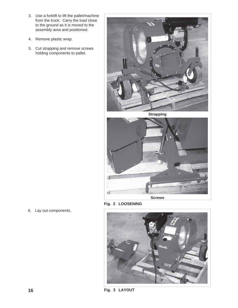
Fig. 2 LOOSENING
3. Use a forklift to lift the pallet/machinefrom the truck. Carry the load closeto the ground as it is moved to theassembly area and positioned.
4. Remove plastic wrap.
5. Cut strapping and remove screwsholding components to pallet.
Screws
Strapping
Fig. 3 LAYOUT
6. Lay out components.

17
Fig. 4 CONTROL CABLE STAND
Removal
Installation
Tightening
7. Mount the control cablestand.
a. Remove the nuts from thestand rod.
b. Mount the rod into theframe and install thenuts.
c. Tighten nuts to theirspecified torque.

18
10. Lower the jack and set themachine on the workingsurface.
Fig. 6 WORKING AREA
Fig. 5 PALLET REMOVAL
8. Wrap the control moduleand cable back over theframe.
9. Use a forklift crane or hoistto lift the machine and backaway from the pallet orslide it out of the way.
Jack
Placement

19
11. Mount the deflector to thedischarge outlet. Be sure toalign arrows when mounting.
12. Tighten fasteners to theirspecified torque.
Fig. 7 DEFLECTOR
Fastener Removal
Arrows
Installing

20
13. Connect the battery cablesand tighten fasteners to theirspecified torque.
Fig. 8 BATTERY CABLE

5 OPERATION
21
OPERATING SAFETY
AgriMetal Front mount Leaf Blowers are designedto quickly and efficiently, blow away leaves,cuttings and other debris. The material is con-veyed on a stream of high velocity air to remove itfrom the area of concern. When the material isremoved, it gives a neat, professional look to theworking area.
In addition to the design and configuration ofequipment, hazard control and accident pre-vention are dependent upon the awareness,concern, prudence and proper training ofpersonnel involved in the operation, transport,maintenance and storage of equipment. It isthe responsibility of the owner or operator toread this manual and to train all other opera-tors before they start working with the ma-chine.
Follow all safety instructions exactly. Safetyis everyone's business. By following recom-mended procedures, a safe working environ-ment is provided for the operator, bystandersand the area around the worksite. Untrainedoperators are not qualified to operate themachine.
Many features incorporated into this machine arethe result of suggestions made by customers likeyou. Read this manual carefully to learn how tooperate the machine safely and how to set it toprovide maximum field efficiency. By following theoperating instructions in conjunction with a goodmaintenance program, your Front mount LeafBlower will provide many years of trouble-freeservice.
5.1 TO THE NEW OPERATOR OR OWNER
• Please remember it is important that youread and heed the safety signs on the LeafBlower. Clean or replace all safety signs ifthey cannot be clearly read and understood.
• If a safety shield or guard is removed for anyreason, it must be replaced before themachine is again operated.
• Always use two people to handle heavy,unwieldy components during assembly,installation, removal or moving.
• Place all controls in neutral, stop engine, setpark brake, remove ignition key and wait forall moving parts to stop before servicing,adjusting, repairing or unplugging.
• Do not allow riders on the machine or pushvehicle at any time. There is no safe placefor any riders.
• Do not allow anyone who is not familiar withthe safety rules and operation instructions touse this machine.
• Never allow children to operate or be aroundthis machine.
• Do not reach into blower openings when theengine is running. Clear the work area ofobjects which might be picked up andsnagged or entangled in the machine.
• Clear the work area of objects which mightbe picked up and snagged or entangled inthe machine.
• Do not reach into blower openings when theengine is running. Keep others away also.
• Keep hands, feet, hair, jewelry, and clothingaway from all moving and/or rotating parts.
• Do not direct the air stream toward people,animals or buildings to prevent injury ordamage.
• Do not place hands, feet or other body partsinto air stream.

22
5.2 MACHINE COMPONENTS
The AgriMetal Front mountLeaf Blower is a large blowermounted on a trailer for mov-ing debris on a stream of air.The air stream can be directedto the right , left or downdepending on the duct posi-tion. A gas engine on the frontframe powers the blower. Thethrottle and duct positioncontrols are located on anumbilical cord that extends tothe pushing vehicle. Anelectric solenoid moves theduct to the desired position.
Adapters for mounting to JohnDeere, Kubota and Torogarden equipment is available.
A Discharge DuctB Duct Position ControlC BlowerD Gas EngineE Throttle ControlF Duct Position DriveG Umbilical CordH Blower Air Intake
Fig. 9 PRINCIPLE COMPONENTS
C
H
D
B E
G
G
AH
D C
FG
A
H
CD

23
5.3 BREAK-IN
Although there are no operational restrictions onthe Blower when it is used for the first time, it isrecommended that the following mechanical itemsbe checked:
A. After operating for 1 hour:
1. Torque all fasteners and hardware.
2. Check condition of blower bearings.
3. Check tire pressure. Inflate as required.
4. Check engine fluid levels. Top up asrequired.
B. After operating for 10 hours:
1. Repeat steps 1 through 4 listed above.(Section A).
2. Change engine oil.
3. Go to the normal servicing and mainte-nance schedule as defined in the Mainte-nance Section.
5.4 PRE-OPERATION CHECKLIST
Efficient and safe operation of the AgriMetal Frontmount Leaf Blower requires that each operatorreads and understands the operating proceduresand all related safety precautions outlined in thissection. A pre-operation checklist is provided forthe operator. It is important for both personalsafety and for maintaining the machine in goodmechanical condition that this checklist be fol-lowed.
Before operating the Blower and each timethereafter, the following areas should be checkedoff:
1. Lubricate the machine per the scheduleoutline in the Maintenance Section.
2. Check that all bearings turn freely. Replaceany that are rough or seized.
3. Make sure that all guards and shields are inplace, secured and functioning as designed.
4. Clean the screen over the blower intake.
5. Check engine oil and fuel level. Top up asrequired.

24
5.5 CONTROLS
Before starting to work, all operators should familiarizethemselves with the location and function of the con-trols.
1. Gas Engine:Read the engine manufacturers operator's manualbefore starting for more detailed instructions.
a. Ignition Switch:This key operated switch controls the electricpower to the engine.
OFF - Turn the key fully counterclockwise tostop the fuel flow and turn the engine off.
RUN - Turn clockwise on detent to the runposition. This is the position where theengine will continue to run.
START - Turn fully clockwise to the last spring-loaded detent position to engage thestarter solenoid and start the engine.Release the key when the engine startsand it will return to the RUN position.
b. Choke:This wire loop controls the position of thechoke. Push the loop in to close the choke forstarting when the engine is cold. Pull the loopout to open the choke as the engine warms.Always pull the loop fully out when operatingthe machine.
2. Control Module:Each machine is equipped with a remote controlmodule that attaches to the power unit. Be familiarwith each control before starting.
Fig. 10 IGNITION SWITCH
Fig. 11 CHOKE
NOTEWatch the position of the ductto determine its position.
a. Rotary Switch:This rotary switch controls the power to the duct positionactuator. Turn the switch to the right and hold to move thecenter duct to the right. Turn and hold to the left to movethe center duct to the left. Release the switch and thecenter duct will stop moving.
b. Throttle:This lever controls the throttle position on the gas enginethrough a push-pull cable. Move the lever toward thecable to increase engine RPM and away to decrease. Fig. 12 CONTROL MODULE
a
ab
b

5.6 ATTACHING/UNHOOKING
25
Fig. 13 FRONT BUMPER REMOVAL
The Blower is designed to be used on John DeereGators and Turf TX, Toro Twister and KubotaRTV 900 power units in a push mode. Each mustbe configured to accept the mounting bracket.
Removing
Removed
5.6.1 JOHN DEERE GATOR AND TURF TX
To attach the JD Gator or Turf TX, follow thisprocedure:
1. Clear the area of bystanders,especially small children.
2. Place all controls in neutral,set park brake, remove ignitionkey and wait for all movingparts to stop.
3. Remove the front bumper fromthe power unit.
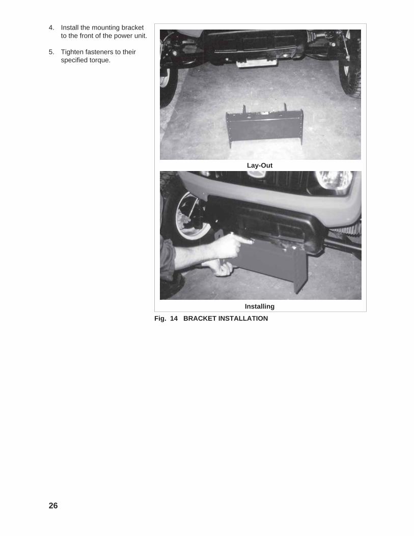
Fig. 14 BRACKET INSTALLATION
26
4. Install the mounting bracketto the front of the power unit.
5. Tighten fasteners to theirspecified torque.
Lay-Out
Installing

27
Fig. 15 ATTACHING
Aligning
Installing
6. Attach the power unit to theblower:
a. Move the power unit upto the blower.
Retainer
b. Remove the mounting pinretainer and mountingpin.
c. Move power unit aheadand align holes.
d. Install mounting pin andretainer.

28
Fig. 16 JACK
7. Raise jack.
8. Level frame.

29
9. Mount the control module tothe power unit:
a. Remove fasteners fromthe control bracket.
Fig. 17 CONTROL MODULE
Fasteners
Mounting
Module
Mounted
b. Mount bracket tohandhold.
c. Mount control module tobracket.
d. Secure module with knob.
e. Tighten all fasteners totheir specified torque.
30
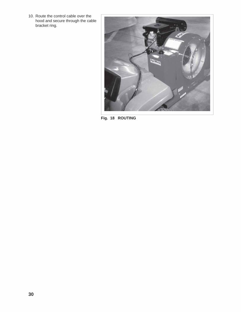
Fig. 18 ROUTING
10. Route the control cable over thehood and secure through the cablebracket ring.

31
Fig. 19 FRONT BUMPER REMOVAL
Removing
Removed
5.6.2 TORO TWISTER
To attach the Toro Twister, follow this procedure:
1. Clear the area ofbystanders, especiallysmall children.
2. Place all controls inneutral, set parkbrake, remove ignitionkey and wait for allmoving parts to stop.
3. Remove the frontbumper from thepower unit.
32
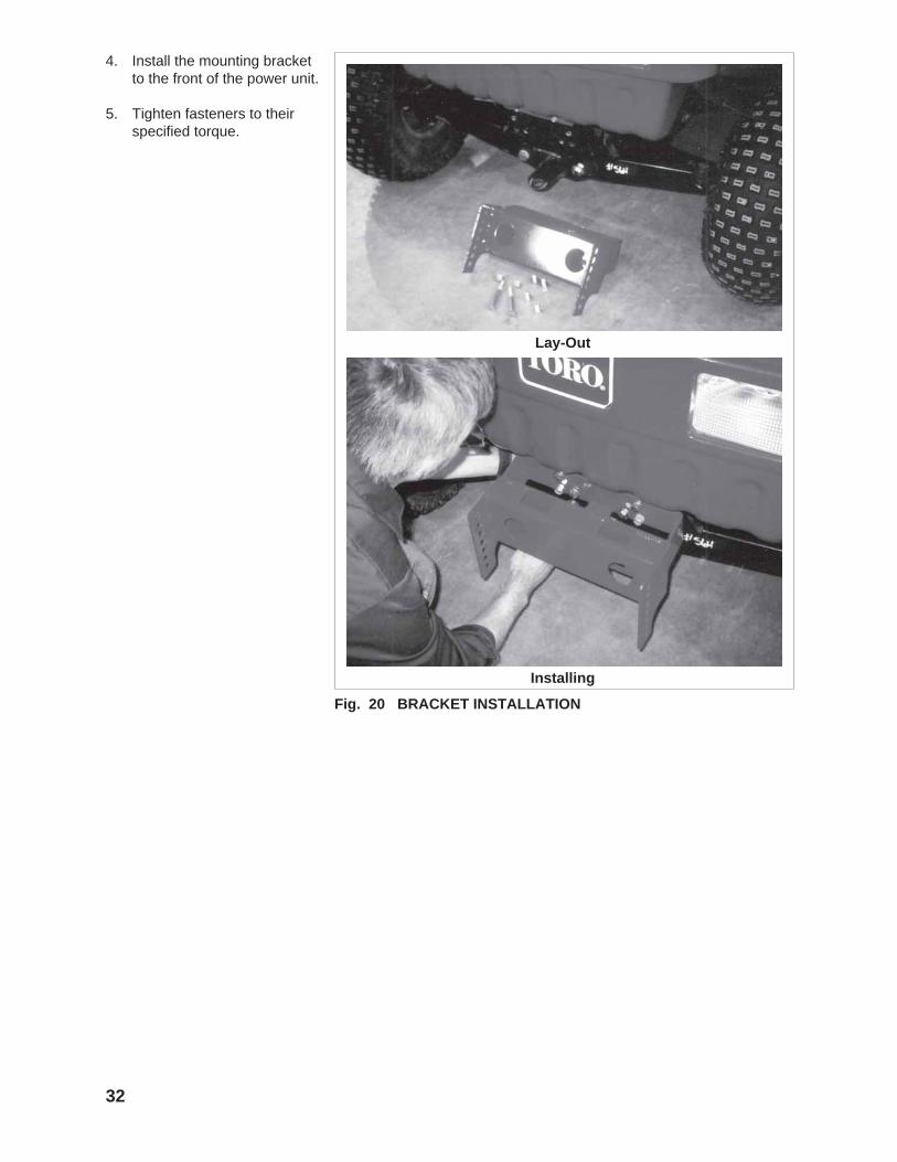
Fig. 20 BRACKET INSTALLATION
4. Install the mounting bracketto the front of the power unit.
5. Tighten fasteners to theirspecified torque.
Lay-Out
Installing
33
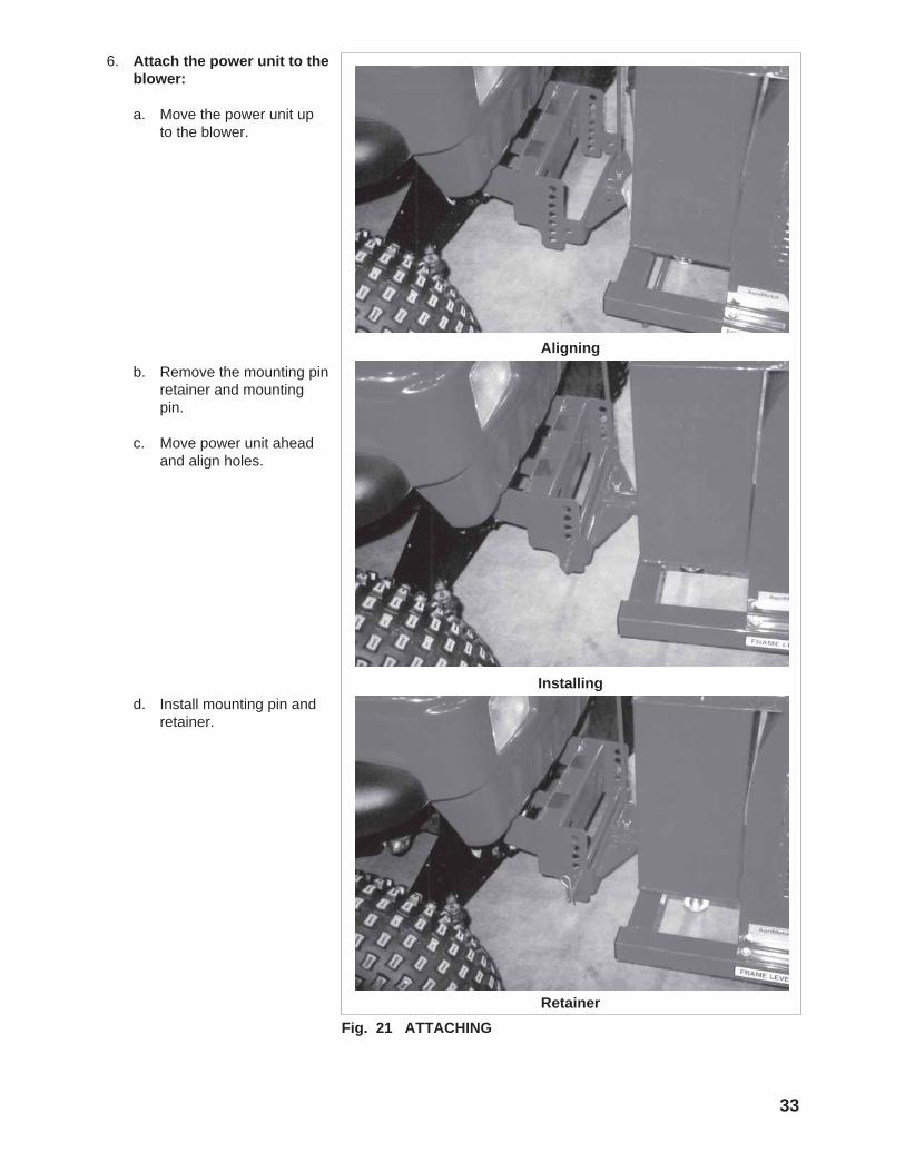
Fig. 21 ATTACHING
Aligning
Installing
6. Attach the power unit to theblower:
a. Move the power unit upto the blower.
Retainer
b. Remove the mounting pinretainer and mountingpin.
c. Move power unit aheadand align holes.
d. Install mounting pin andretainer.

34
Fig. 22 JACK
7. Raise jack.
8. Level frame.
35
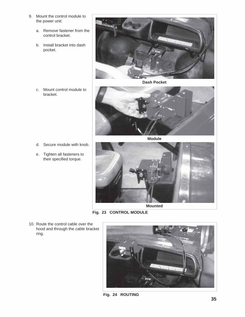
9. Mount the control module tothe power unit:
a. Remove fastener from thecontrol bracket.
b. Install bracket into dashpocket.
Fig. 23 CONTROL MODULE
Dash Pocket
Module
Mounted
c. Mount control module tobracket.
d. Secure module with knob.
e. Tighten all fasteners totheir specified torque.
Fig. 24 ROUTING
10. Route the control cable over thehood and through the cable bracketring.

Fig. 25 FRONT BUMPER REMOVAL
Low Bumper
Removing
5.6.3 KUBOTA RTV 900
To attach the Kubota RTV 900, follow this proce-dure:
1. Clear the area ofbystanders, especiallysmall children.
2. Place all controls inneutral, set parkbrake, remove ignitionkey and wait for allmoving parts to stop.
3. Remove the low frontbumper from thepower unit.
36

37Fig. 26 BRACKET INSTALLATION
4. Install the mounting bracketto the front of the power unit.
Lay-Out
Fasteners
Mounting
Lock Pin
5. Tighten fasteners to theirspecified torque.
6. Install the lock pin andretainer.
38
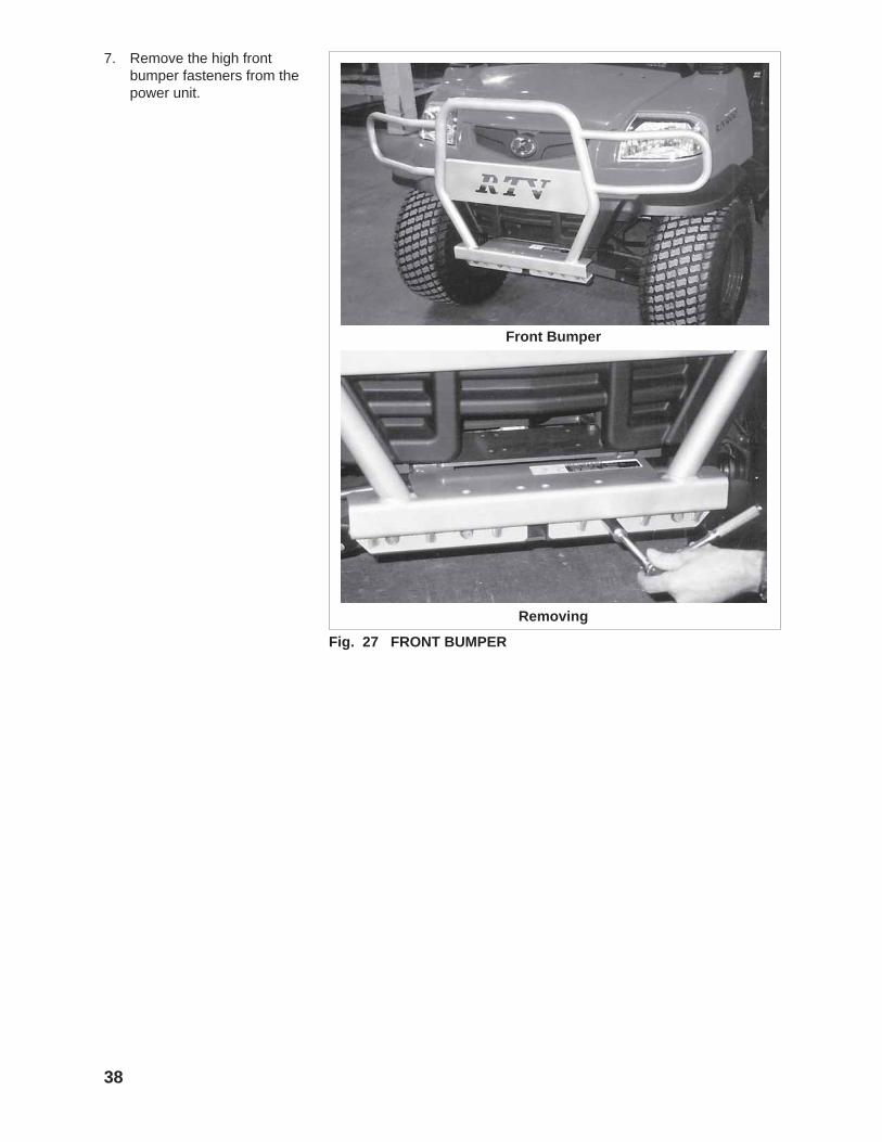
7. Remove the high frontbumper fasteners from thepower unit.
Fig. 27 FRONT BUMPER
Front Bumper
Removing

39
8. Install the mounting bracketto the front of the powerunit.
a. Slide the bracket intothe pocket.
Fig. 28 BRACKET INSTALLATION
Lay-Out
Spacer
Installing
Tightening
b. Install spacers on eachend of bracket.
c. Tighten fasteners to theirspecified torque.
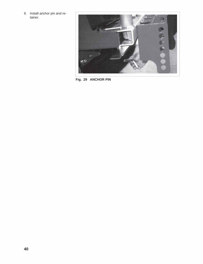
9. Install anchor pin and re-tainer.
Fig. 29 ANCHOR PIN
40
41
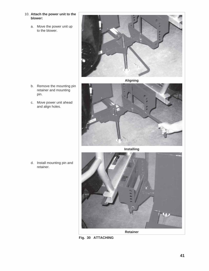
Fig. 30 ATTACHING
Aligning
Installing
10. Attach the power unit to theblower:
a. Move the power unit upto the blower.
Retainer
b. Remove the mounting pinretainer and mountingpin.
c. Move power unit aheadand align holes.
d. Install mounting pin andretainer.

42
Fig. 31 JACK
11. Raise jack.
Fig. 32 LEVEL FRAME
12. Level frame.

43Fig. 33 CONTROL MODULE
Fasteners
Module
Mounting
Mounted
13. Mount the control module tothe power unit:
a. Remove fastener from thecontrol bracket.
b. Mount bracket to cabframe.
c. Mount control module tobracket.
d. Secure module with knob.
e. Tighten all fasteners totheir specified torque.
44
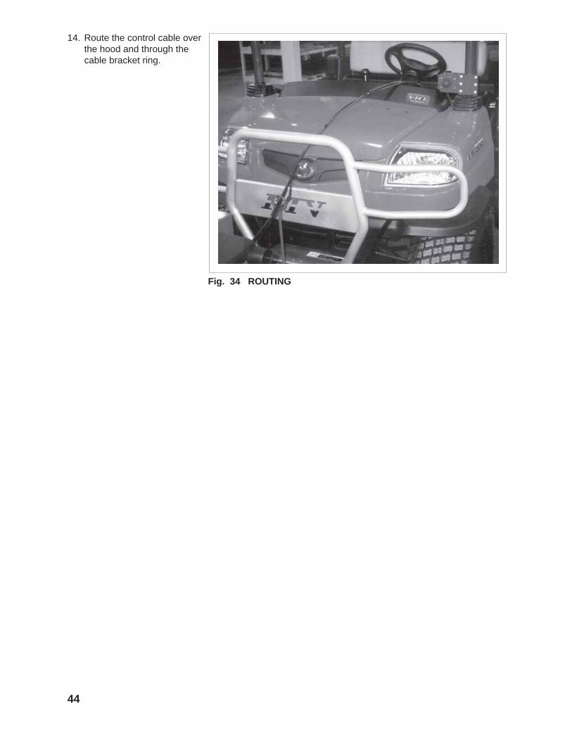
Fig. 34 ROUTING
14. Route the control cable overthe hood and through thecable bracket ring.
45
5.7 FIELD OPERATION
Although the Leaf Blower is easy to use, eachoperator should review this section to familiarizehimself with the detailed safety and operatingprocedures. When using the machine, follow thisprocedure:
1. Clear the area of bystanders, especially smallchildren.
2. Review and follow the Pre-Operation Check-list (see Section 5.4).
3. Attach the machine to the push vehicle (seeSection 5.6). Be sure the frame is level.
4. Transport to the working area (refer to Section5.8).
OPERATING SAFETY• Please remember it is important that you
read and heed the safety signs on the LeafBlower. Clean or replace all safety signs ifthey cannot be clearly read and understood.
• If a safety shield or guard is removed for anyreason, it must be replaced before themachine is again operated.
• Always use two people to handle heavy,unwieldy components during assembly,installation, removal or moving.
• Place all controls in neutral, stop engine, setpark brake, remove ignition key and wait forall moving parts to stop before servicing,adjusting, repairing or unplugging.
• Do not allow riders on the machine or pushvehicle at any time. There is no safe placefor any riders.
• Do not allow anyone who is not familiar withthe safety rules and operation instructions touse this machine.
• Never allow children to operate or be aroundthis machine.
• Do not reach into blower openings when theengine is running. Clear the work area ofobjects which might be picked up andsnagged or entangled in the machine.
• Clear the work area of objects which mightbe picked up and snagged or entangled inthe machine.
• Do not reach into blower openings when theengine is running. Keep others away also.
• Keep hands, feet, hair, jewelry, and clothingaway from all moving and/or rotating parts.
• Do not direct the air stream toward people,animals or buildings to prevent injury ordamage.
• Do not place hands, feet or other body partsinto air stream.

5. Starting Machine:
a. Stop utility vehicle engine, set parkbrake, remove ignition key and waitfor all moving parts to stop beforedismounting.
c. Close the choke if the engine iscold.
d. Move the throttle to its 1/4 throttleposition.
e. Use the ignition switch on the frontframe to start the engine.
f. Run the engine for a few minutesto allow it to warm.
g. Gradually open the choke.
h. Increase throttle setting to maxi-mum speed for operation.
46
Fig. 35 IGNITION SWITCH
Fig. 36 WORKING
To Left
To Right
i. Start push vehicle engineto start working.
6. Use the rotary switch to setthe position of the centerduct.
7. Travel Speed:Set the travel speed appro-priate for the job being done.Travel faster if all the debrisis being blown away. Slowdown if some debris is notbeing removed.
47
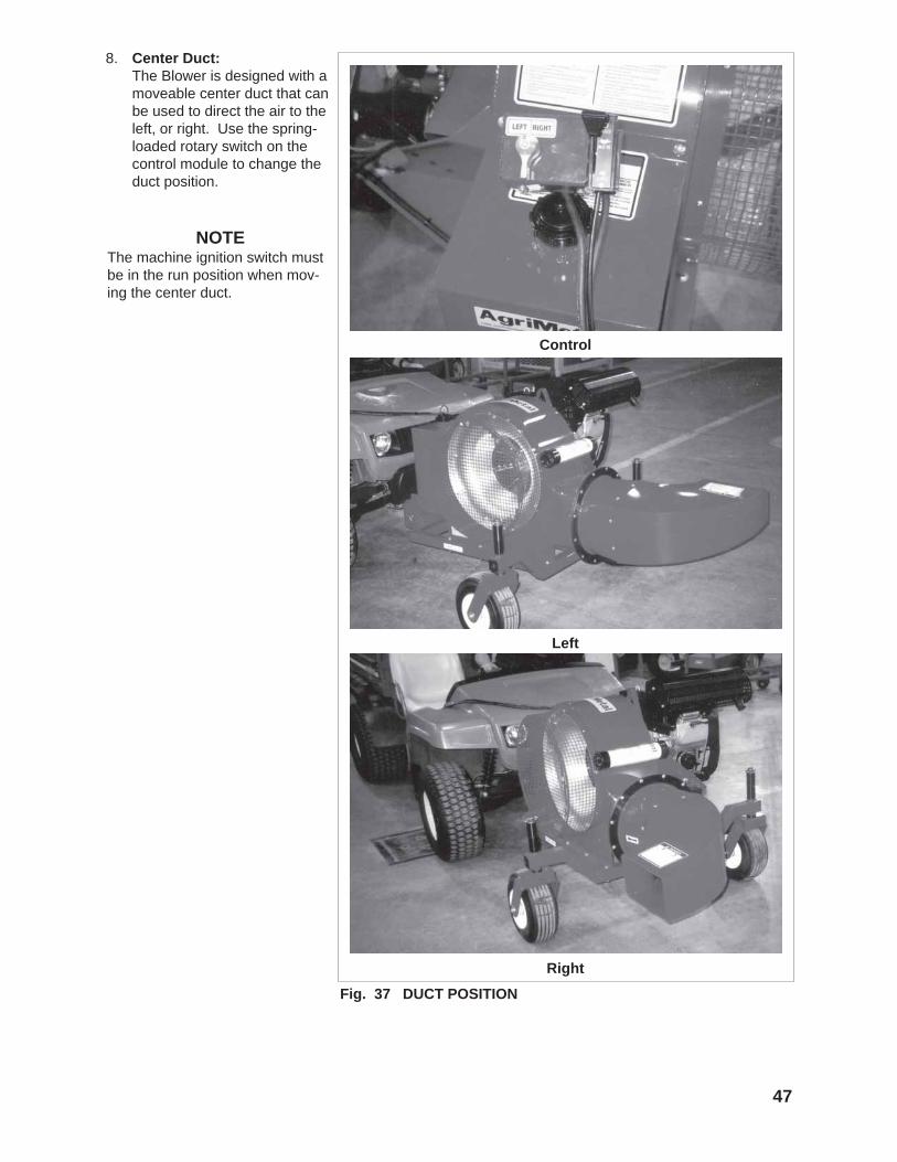
Fig. 37 DUCT POSITION
Control
Left
Right
8. Center Duct:The Blower is designed with amoveable center duct that canbe used to direct the air to theleft, or right. Use the spring-loaded rotary switch on thecontrol module to change theduct position.
NOTEThe machine ignition switch mustbe in the run position when mov-ing the center duct.

48
9. Castor Wheel Height:
a. The castor shaft on thewheels can be set in thehigh, middle or lowposition to fit anyapplication. Eachmachine is shippedfrom the factory with theshafts in the highposition. Refer toMaintenance section forconversion procedure.
Fig. 38 AXLE HEIGHT
Middle
HighNOTE
It may be necessary tochange hitch configura-tion when axle heightchanges to keep thehitch/frame level.
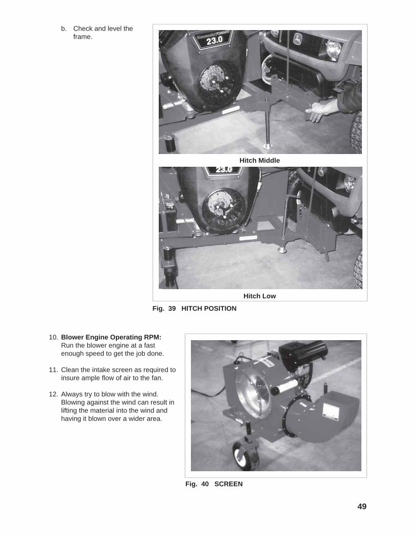
Fig. 40 SCREEN
49
b. Check and level theframe.
Fig. 39 HITCH POSITION
Hitch Low
Hitch Middle
10. Blower Engine Operating RPM:Run the blower engine at a fastenough speed to get the job done.
11. Clean the intake screen as required toinsure ample flow of air to the fan.
12. Always try to blow with the wind.Blowing against the wind can result inlifting the material into the wind andhaving it blown over a wider area.
50
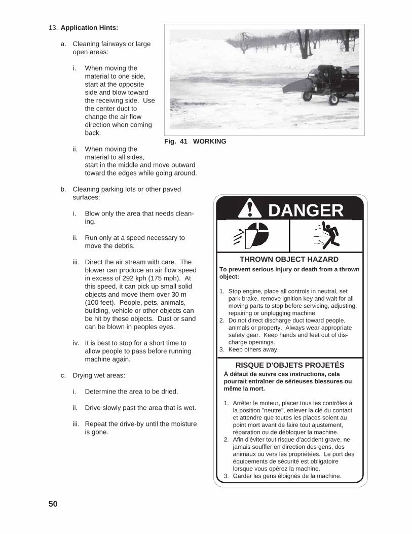
13. Application Hints:
a. Cleaning fairways or largeopen areas:
i. When moving thematerial to one side,start at the oppositeside and blow towardthe receiving side. Usethe center duct tochange the air flowdirection when comingback.
ii. When moving thematerial to all sides,
DANGER
To prevent serious injury or death from a thrownobject:
1. Stop engine, place all controls in neutral, setpark brake, remove ignition key and wait for allmoving parts to stop before servicing, adjusting,repairing or unplugging machine.
2. Do not direct discharge duct toward people,animals or property. Always wear appropriatesafety gear. Keep hands and feet out of dis-charge openings.
3. Keep others away.
THROWN OBJECT HAZARD
RISQUE D'OBJETS PROJETÉSÁ défaut de suivre ces instructions, celapourrait entraîner de sérieuses blessures oumême la mort.
1. Arrêter le moteur, placer tous les contrôles àla position "neutre", enlever la clé du contactet attendre que toutes les places soient aupoint mort avant de faire tout ajustement,réparation ou de débloquer la machine.
2. Afin d'éviter tout risque d'accident grave, nejamais souffler en direction des gens, desanimaux ou vers les propriétées. Le port deséquipements de sécurité est obligatoirelorsque vous opérez la machine.
3. Garder les gens éloignés de la machine.
Fig. 41 WORKING
start in the middle and move outwardtoward the edges while going around.
b. Cleaning parking lots or other pavedsurfaces:
i. Blow only the area that needs clean-ing.
ii. Run only at a speed necessary tomove the debris.
iii. Direct the air stream with care. Theblower can produce an air flow speedin excess of 292 kph (175 mph). Atthis speed, it can pick up small solidobjects and move them over 30 m(100 feet). People, pets, animals,building, vehicle or other objects canbe hit by these objects. Dust or sandcan be blown in peoples eyes.
iv. It is best to stop for a short time toallow people to pass before runningmachine again.
c. Drying wet areas:
i. Determine the area to be dried.
ii. Drive slowly past the area that is wet.
iii. Repeat the drive-by until the moistureis gone.

Table 1 Travel Speed vs. Weight Ratio
Road Speed
Up to 32 km/h(20 mph)
Up to 16 km/h(10 mph)
Do not push
Weight of fully equipped orloaded implement(s) relative
to weight of push vehicle
1 to 1, or less
2 to 1, or less
More than 2 to 1
5.8 TRANSPORTING
51
TRANSPORT SAFETY
• Comply with state and local laws governinghighway safety and movement of machineryon public roads.
• The use of flashing amber lights is accept-able in most localities. However, somelocalities prohibit their use. Local lawsshould be checked for all highway lightingand marking requirements.
• At all times when driving the utility vehicleand equipment on the road or highwayunder 20 mph (32 kph), use flashing amberwarning lights and a slow moving vehicle(SMV) identification emblem. Do not exceed20 mph (32 kph). Reduce speed on roughroads and surfaces.
• Plan your route to avoid heavy traffic.
• Use a mounting pin with provisions for aretainer. Install the retainer.
• Do not drink and drive.
• Be a safe and courteous driver. Alwaysyield to oncoming traffic in all situations,including narrow bridges, intersections, etc.Watch for traffic when operating near orcrossing roadways.
• Never allow riders on either push vehicle ormachine.
When transporting the machine, review and followthese instructions:
1. Clear the area of bystanders, especially smallchildren.
2. Be sure that the pushing unit has sufficientsize and mass to control the Leaf Blowerduring transport.
3. Insure that the machine is securely attachedto the push vehicle with a mechanical retainerthrough the mounting pin.
4. Do not allow riders on blower.
5. Never exceed a safe travel speed. Nevertravel faster than 32 kph (20 mph) The ratioof the push vehicle weight to the machineweight plays an important role in definingacceptable travel speed. The following tablesummarizes the weight ratio to travel speed.
6. Always shift to a lower gear when going downhill to use the engine as a restraining force.
7. Apply the brakes carefully to prevent loosingcontrol.
8. Never disengage utility vehicle drivetrain andcoast down hills. Always keep utility vehicle ingear.

5.9 STORAGE
52
STORAGE SAFETY
• Store the unit in an area away from humanactivity.
• Do not permit children to play on or aroundthe stored machine.
• Store the unit in a dry, level area. Supportthe frame with planks if required.
At the end of the season, the machine should bethoroughly inspected and prepared for storage.Repair or replace any worn or damaged compo-nents to prevent any unnecessary down time atthe beginning of the next season. Follow thisprocedure:
Fig. 42 STORED
1. Thoroughly washthe machine with apressure washer orwater hose toremove all dirt,mud, debris orresidue.
2. Make sure all thewater drains out ofthe blower and ductcompartments.
3. Lubricate all greasepoints to removeany water residuefrom washing.
4. Coat the roller chaincoupler with a goodquality chain lubri-cant to preventrusting.
5. Remove any material that has becomeentangled around any moving part.
6. Run the machine for a couple of minutes atlow RPM to dry the inside of the blower andduct.
7. Touch up all paint nicks and scratches toprevent rusting.
8. Move the machine to its storage area.
9. Store in a dry, level spot.
10. Store in an enclosed building if possible. Ifspace is not available, cover with a waterprooftarpaulin and tie down securely.
11. Unhook from the push vehicle (see Section5.6).
12. Place planks under the hitch and tires foradded support if required.
13. Store in an area away from human activity.
14. Do not allow children to play around thestored unit.
53
6 SERVICE AND MAINTENANCE
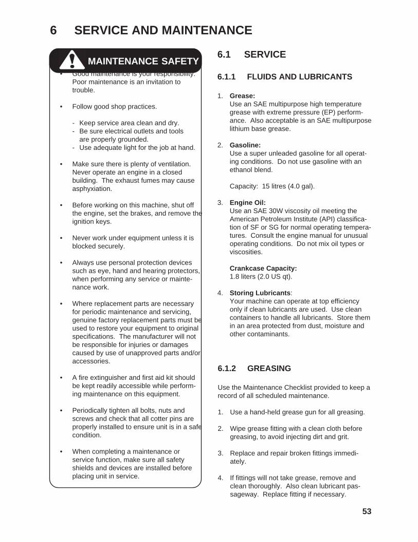
MAINTENANCE SAFETY6.1 SERVICE
6.1.1 FLUIDS AND LUBRICANTS
1. Grease:Use an SAE multipurpose high temperaturegrease with extreme pressure (EP) perform-ance. Also acceptable is an SAE multipurposelithium base grease.
2. Gasoline:Use a super unleaded gasoline for all operat-ing conditions. Do not use gasoline with anethanol blend.
Capacity: 15 litres (4.0 gal).
3. Engine Oil:Use an SAE 30W viscosity oil meeting theAmerican Petroleum Institute (API) classifica-tion of SF or SG for normal operating tempera-tures. Consult the engine manual for unusualoperating conditions. Do not mix oil types orviscosities.
Crankcase Capacity:1.8 liters (2.0 US qt).
4. Storing Lubricants:Your machine can operate at top efficiencyonly if clean lubricants are used. Use cleancontainers to handle all lubricants. Store themin an area protected from dust, moisture andother contaminants.
6.1.2 GREASING
Use the Maintenance Checklist provided to keep arecord of all scheduled maintenance.
1. Use a hand-held grease gun for all greasing.
2. Wipe grease fitting with a clean cloth beforegreasing, to avoid injecting dirt and grit.
3. Replace and repair broken fittings immedi-ately.
4. If fittings will not take grease, remove andclean thoroughly. Also clean lubricant pas-sageway. Replace fitting if necessary.
• Good maintenance is your responsibility.Poor maintenance is an invitation totrouble.
• Follow good shop practices.
- Keep service area clean and dry.- Be sure electrical outlets and tools
are properly grounded.- Use adequate light for the job at hand.
• Make sure there is plenty of ventilation.Never operate an engine in a closedbuilding. The exhaust fumes may causeasphyxiation.
• Before working on this machine, shut offthe engine, set the brakes, and remove theignition keys.
• Never work under equipment unless it isblocked securely.
• Always use personal protection devicessuch as eye, hand and hearing protectors,when performing any service or mainte-nance work.
• Where replacement parts are necessaryfor periodic maintenance and servicing,genuine factory replacement parts must beused to restore your equipment to originalspecifications. The manufacturer will notbe responsible for injuries or damagescaused by use of unapproved parts and/oraccessories.
• A fire extinguisher and first aid kit shouldbe kept readily accessible while perform-ing maintenance on this equipment.
• Periodically tighten all bolts, nuts andscrews and check that all cotter pins areproperly installed to ensure unit is in a safecondition.
• When completing a maintenance orservice function, make sure all safetyshields and devices are installed beforeplacing unit in service.

54
6.1.3 SERVICING INTERVALS
The period recommended is based on normaloperating conditions. Severe or unusual condi-tions may require more frequent lubrication or oilchanges.
8 Hours or Daily
Fig. 43 AIR INTAKE SCREEN
Fig. 44 DIPSTICK
1. Clean blower air intake screen.
2. Check engine oil level.

50 Hours
1. Change engine oil.
Fig. 46 ENGINE DRAIN PLUG
Fig. 47 AIR CLEANER
2. Clean air cleaner.
3. Check tire pressure. Pressurize to(25 psi) maximum.
55
Fig. 45 GAS TANK
3. Check fuel level.
100 Hours
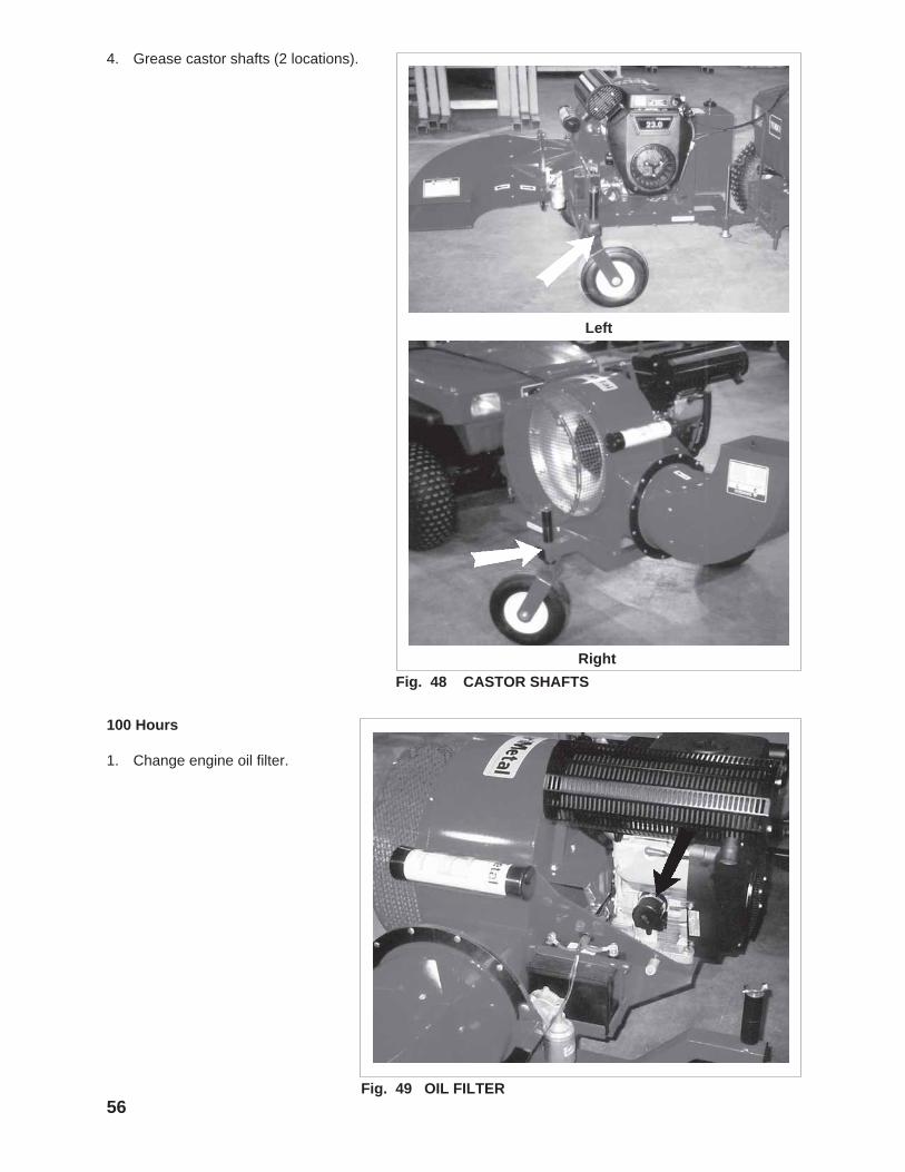
1. Change engine oil filter.
Fig. 49 OIL FILTER56
Fig. 48 CASTOR SHAFTS
4. Grease castor shafts (2 locations).
Right
Left
57
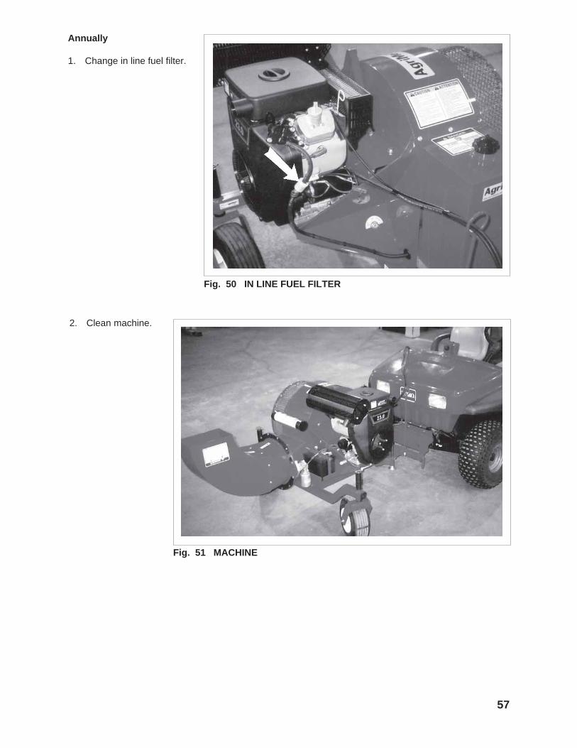
Annually
1. Change in line fuel filter.
Fig. 50 IN LINE FUEL FILTER
Fig. 51 MACHINE
2. Clean machine.

6.1.4 SERVICE RECORD
See Lubrication and Maintenance sections for details of service. Copy this page to continue record.
ACTION CODE: CK CHECK CL CLEAN G GREASE CH CHANGE
HOURS
SERVICED BY
MAINTENANCE
CL Blower Air Intake Screen
CK Engine Oil Level
8 Hours or Daily
CK Fuel Level
CH Engine Oil
50 Hours
CL Air Cleaner
CH Engine Oil Filter
100 Hours
CH Inline Fuel Filter
Annually
CL Machine
58
CK Tire Pressure
G Castor Shafts (2)

6.2 MAINTENANCE
59
By following a careful service and maintenanceprogram for your machine, you will enjoy manyyears of trouble-free operation.
1. Review the Operator'sManual for the engine.
2. Place all controls in neutral,stop engine and removeignition key before maintain-ing.
3. Remove the cover over theair cleaner.
4. Remove the foam from theengine.
5. Use an air hose to blow thedust and debris out of thefoam.
6. Install foam.
7. Install and secure the cover.
6.2.1 CLEANING AIR CLEANER
Fig. 52 AIR CLEANER
60
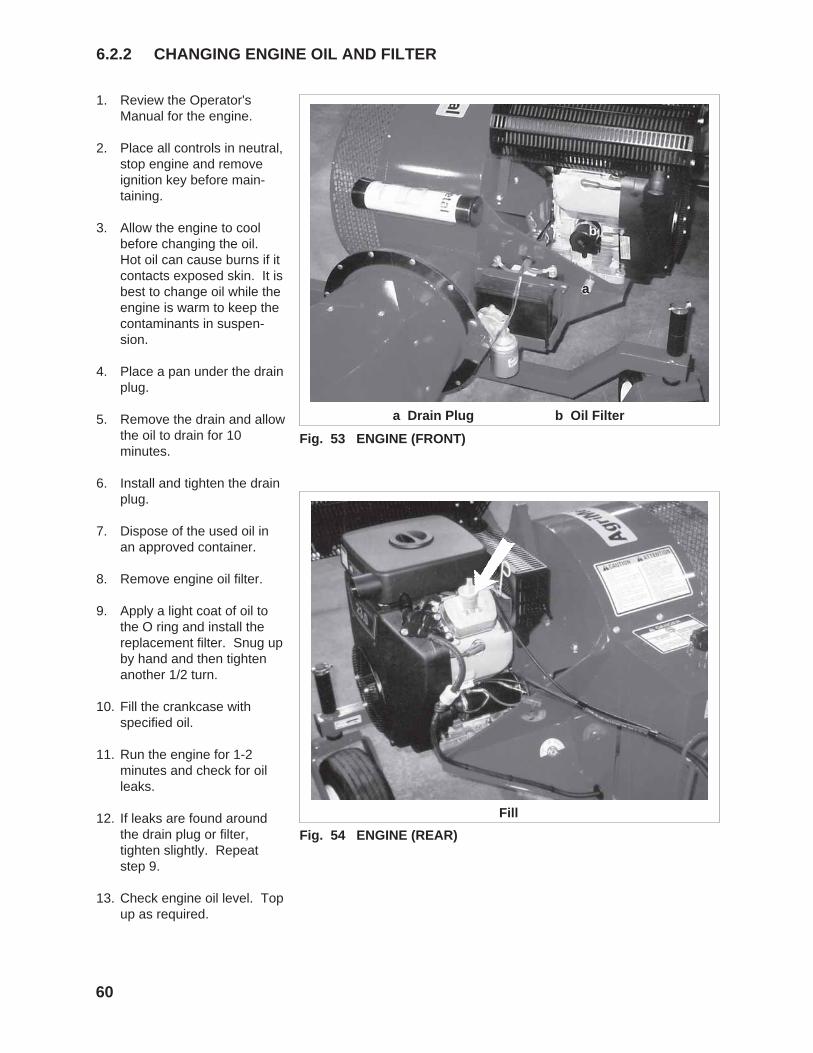
1. Review the Operator'sManual for the engine.
2. Place all controls in neutral,stop engine and removeignition key before main-taining.
3. Allow the engine to coolbefore changing the oil.Hot oil can cause burns if itcontacts exposed skin. It isbest to change oil while theengine is warm to keep thecontaminants in suspen-sion.
4. Place a pan under the drainplug.
5. Remove the drain and allowthe oil to drain for 10minutes.
6. Install and tighten the drainplug.
7. Dispose of the used oil inan approved container.
8. Remove engine oil filter.
9. Apply a light coat of oil tothe O ring and install thereplacement filter. Snug upby hand and then tightenanother 1/2 turn.
10. Fill the crankcase withspecified oil.
11. Run the engine for 1-2minutes and check for oilleaks.
12. If leaks are found aroundthe drain plug or filter,tighten slightly. Repeatstep 9.
13. Check engine oil level. Topup as required.
6.2.2 CHANGING ENGINE OIL AND FILTER
Fig. 53 ENGINE (FRONT)
a Drain Plug b Oil Filter
Fig. 54 ENGINE (REAR)
Fill
a
b
61
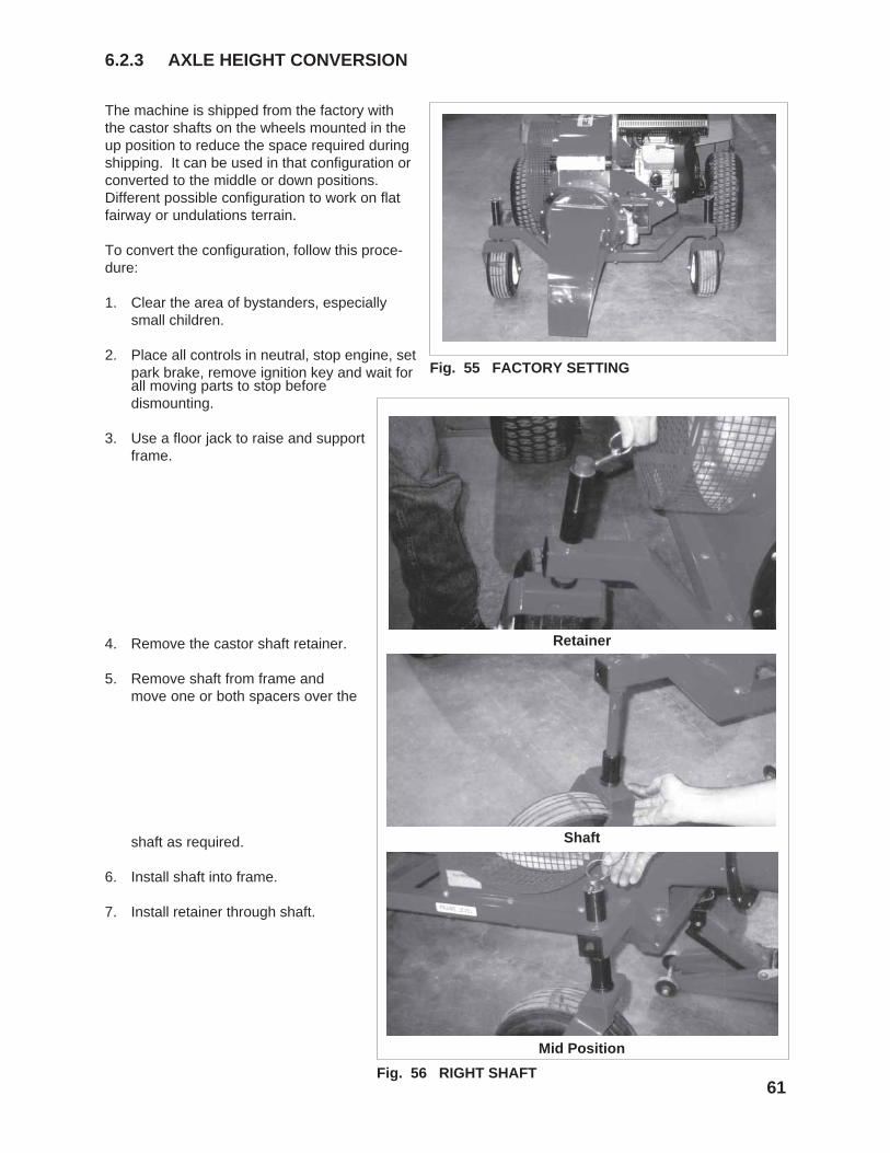
The machine is shipped from the factory withthe castor shafts on the wheels mounted in theup position to reduce the space required duringshipping. It can be used in that configuration orconverted to the middle or down positions.Different possible configuration to work on flatfairway or undulations terrain.
To convert the configuration, follow this proce-dure:
1. Clear the area of bystanders, especiallysmall children.
2. Place all controls in neutral, stop engine, setpark brake, remove ignition key and wait for
6.2.3 AXLE HEIGHT CONVERSION
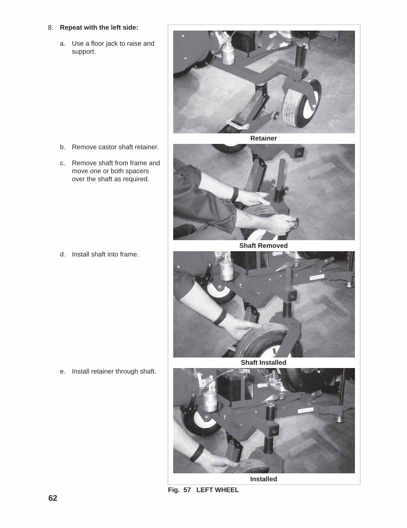
Fig. 56 RIGHT SHAFT
Retainer
Shaft
Fig. 55 FACTORY SETTING
Mid Position
all moving parts to stop beforedismounting.
3. Use a floor jack to raise and supportframe.
4. Remove the castor shaft retainer.
5. Remove shaft from frame andmove one or both spacers over the
shaft as required.
6. Install shaft into frame.
7. Install retainer through shaft.
62
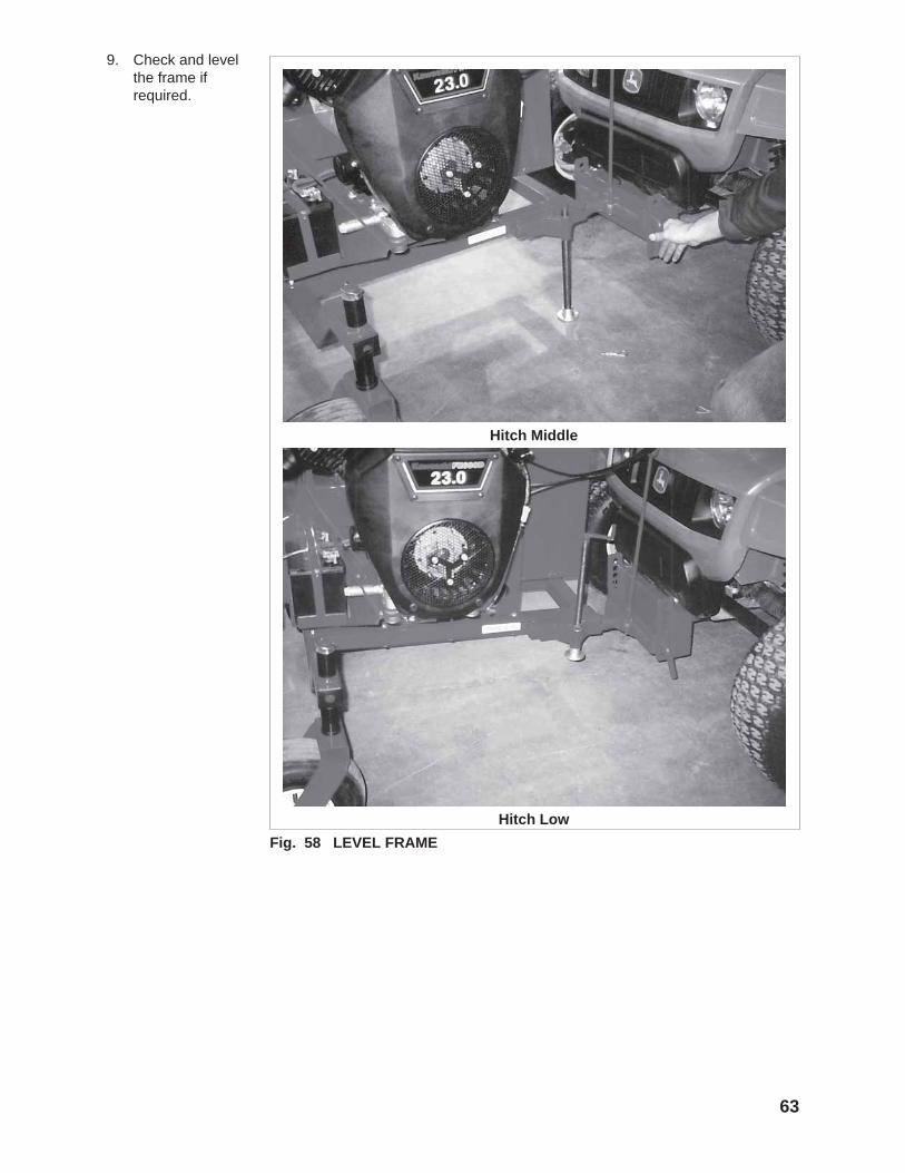
8. Repeat with the left side:
a. Use a floor jack to raise andsupport.
Fig. 57 LEFT WHEEL
Installed
Shaft Installed
Shaft Removed
Retainerb. Remove castor shaft retainer.
c. Remove shaft from frame andmove one or both spacersover the shaft as required.
d. Install shaft into frame.
e. Install retainer through shaft.
63
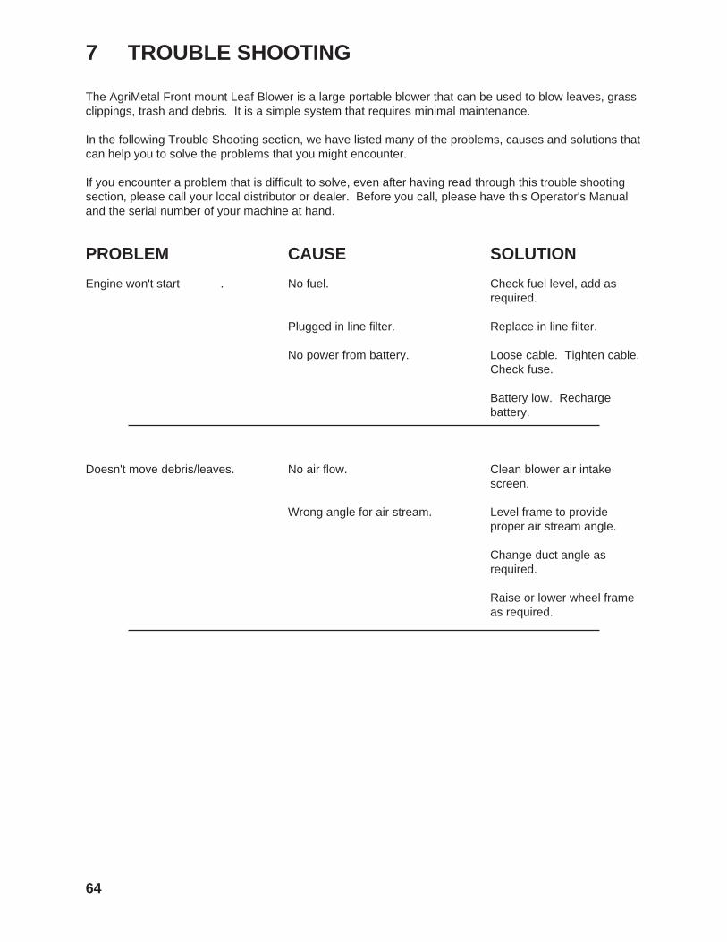
Fig. 58 LEVEL FRAME
9. Check and levelthe frame ifrequired.
Hitch Middle
Hitch Low
64
7 TROUBLE SHOOTING
The AgriMetal Front mount Leaf Blower is a large portable blower that can be used to blow leaves, grassclippings, trash and debris. It is a simple system that requires minimal maintenance.
In the following Trouble Shooting section, we have listed many of the problems, causes and solutions thatcan help you to solve the problems that you might encounter.
If you encounter a problem that is difficult to solve, even after having read through this trouble shootingsection, please call your local distributor or dealer. Before you call, please have this Operator's Manualand the serial number of your machine at hand.
PROBLEM CAUSE SOLUTION
Engine won't start . No fuel. Check fuel level, add asrequired.
Plugged in line filter. Replace in line filter.
No power from battery. Loose cable. Tighten cable.Check fuse.
Battery low. Rechargebattery.
Doesn't move debris/leaves. No air flow. Clean blower air intakescreen.
Wrong angle for air stream. Level frame to provideproper air stream angle.
Change duct angle asrequired.
Raise or lower wheel frameas required.
65
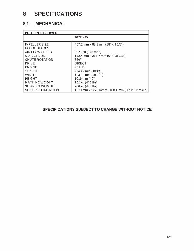
8 SPECIFICATIONS
8.1 MECHANICAL
SPECIFICATIONS SUBJECT TO CHANGE WITHOUT NOTICE
PULL TYPE BLOWERBWF 180
IMPELLER SIZE 457.2 mm x 88.9 mm (18" x 3 1/2") NO. OF BLADES 8 AIR FLOW SPEED 292 kph (175 mph) OUTLET SIZE 152.4 mm x 266.7 mm (6" x 10 1/2") CHUTE ROTATION 360° DRIVE DIRECT ENGINE 23 H.P. 'LENGTH 2743.2 mm (108") WIDTH 1231.9 mm (48 1/2") HEIGHT 1016 mm (40") MACHINE WEIGHT 182 kg (400 lbs) SHIPPING WEIGHT 200 kg (440 lbs) SHIPPING DIMENSION 1270 mm x 1270 mm x 1168.4 mm (50" x 50" x 46")
66
BoltDiameter"A"
1/4"5/16"3/8"7/16"1/2"9/16"5/8"3/4"7/8"1"
(6)(10)(20)(30)(45)(70)(95)
(165)(170)(225)
SAE 2N.m (lb-ft)
SAE 5N.m (lb-ft)
SAE 8N.m (lb-ft)
81327416195
128225230345
12254572
110155215390570850
(9)(19)(33)(53)(80)(115)(160)(290)(420)(630)
173663
1001552203055408801320
(12)(27)(45)(75)
(115)(165)(220)(400)(650)(970)
Bolt Torque *
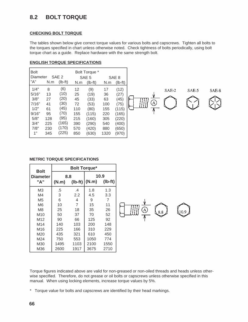
CHECKING BOLT TORQUE
The tables shown below give correct torque values for various bolts and capscrews. Tighten all bolts tothe torques specified in chart unless otherwise noted. Check tightness of bolts periodically, using bolttorque chart as a guide. Replace hardware with the same strength bolt.
ENGLISH TORQUE SPECIFICATIONS
8.2 BOLT TORQUE
Torque figures indicated above are valid for non-greased or non-oiled threads and heads unless other-wise specified. Therefore, do not grease or oil bolts or capscrews unless otherwise specified in thismanual. When using locking elements, increase torque values by 5%.
* Torque value for bolts and capscrews are identified by their head markings.
METRIC TORQUE SPECIFICATIONS
8.8(N.m) (lb-ft)
Bolt Torque*Bolt
Diameter"A"
10.9(N.m) (lb-ft)
M3M4M5M6M8M10M12M14M16M20M24M30M36
.53610255090
14022543575014952600
.42.247183766
10316632155311031917
1.84.59
153570
125200310610105021003675
1.33.3711265292
148229450774
15502710

10 INDEX
PAGE PAGES
Safety ............................................................. 2Battery Safety .......................................... 9Eqiupment Safety..................................... 4Gas Motor Safety ................................... 10General Safety ......................................... 3Maintenance Safety ................................. 9Operating Safety ...................................... 7Preparation .............................................. 6Refuelling Safety ...................................... 8Safety Signs ............................................. 5Safety Training ......................................... 5Sign-Off Form ........................................ 11Storage Safety ......................................... 8Tire Safety ............................................... 8Transport Safety ...................................... 8
Safety Sign Locations ................................... 12Service and Maintenance ............................. 53
Maintenance .......................................... 59 Axle Height Conversion ...................... 61 Changing Engine Oil and Filter ........... 60 Cleaning Air Cleaner .......................... 59
Service ................................................... 53 Fluids and Lubricants ......................... 53 Greasing ............................................. 53 Service Record ................................... 58 Servicing Intervals .............................. 54Specifications ............................................... 65
Bolt Torque ............................................ 66Mechanical ............................................. 65
T
Trouble Shooting .......................................... 64
A
Assembling .................................................... 15Machine Assembly .................................. 15
I
Introduction ..................................................... 1
O
Operation ...................................................... 21 Attaching/Unhooking ................................ 25 John Deere Gator and Turf TX ............ 25 Kubota RTV 900 .................................. 36 Toro Twister ........................................ 31 Break-In .................................................... 23 Controls .................................................... 24 Field Operation ......................................... 45 Machine Components .............................. 22 Pre-Operation Checklist ........................... 23 Storage ..................................................... 52 To the New Operator or Owner ................ 21 Transporting ............................................. 51
P
Parts List ...................................................... 67
79